EP2604307A1 - Peripheral intravenous safety catheter with quick, painless puncture system - Google Patents
Peripheral intravenous safety catheter with quick, painless puncture system Download PDFInfo
- Publication number
- EP2604307A1 EP2604307A1 EP12382423.7A EP12382423A EP2604307A1 EP 2604307 A1 EP2604307 A1 EP 2604307A1 EP 12382423 A EP12382423 A EP 12382423A EP 2604307 A1 EP2604307 A1 EP 2604307A1
- Authority
- EP
- European Patent Office
- Prior art keywords
- catheter
- holder
- cannula
- piscqpps
- quick
- Prior art date
- Legal status (The legal status is an assumption and is not a legal conclusion. Google has not performed a legal analysis and makes no representation as to the accuracy of the status listed.)
- Granted
Links
Images


Classifications
-
- A—HUMAN NECESSITIES
- A61—MEDICAL OR VETERINARY SCIENCE; HYGIENE
- A61B—DIAGNOSIS; SURGERY; IDENTIFICATION
- A61B5/00—Measuring for diagnostic purposes; Identification of persons
- A61B5/14—Devices for taking samples of blood ; Measuring characteristics of blood in vivo, e.g. gas concentration within the blood, pH-value of blood
- A61B5/1405—Devices for taking blood samples
- A61B5/1411—Devices for taking blood samples by percutaneous method, e.g. by lancet
-
- A—HUMAN NECESSITIES
- A61—MEDICAL OR VETERINARY SCIENCE; HYGIENE
- A61M—DEVICES FOR INTRODUCING MEDIA INTO, OR ONTO, THE BODY; DEVICES FOR TRANSDUCING BODY MEDIA OR FOR TAKING MEDIA FROM THE BODY; DEVICES FOR PRODUCING OR ENDING SLEEP OR STUPOR
- A61M25/00—Catheters; Hollow probes
- A61M25/01—Introducing, guiding, advancing, emplacing or holding catheters
- A61M25/06—Body-piercing guide needles or the like
- A61M25/0612—Devices for protecting the needle; Devices to help insertion of the needle, e.g. wings or holders
- A61M25/0631—Devices for protecting the needle; Devices to help insertion of the needle, e.g. wings or holders having means for fully covering the needle after its withdrawal, e.g. needle being withdrawn inside the handle or a cover being advanced over the needle
-
- A—HUMAN NECESSITIES
- A61—MEDICAL OR VETERINARY SCIENCE; HYGIENE
- A61M—DEVICES FOR INTRODUCING MEDIA INTO, OR ONTO, THE BODY; DEVICES FOR TRANSDUCING BODY MEDIA OR FOR TAKING MEDIA FROM THE BODY; DEVICES FOR PRODUCING OR ENDING SLEEP OR STUPOR
- A61M25/00—Catheters; Hollow probes
- A61M25/01—Introducing, guiding, advancing, emplacing or holding catheters
- A61M25/0105—Steering means as part of the catheter or advancing means; Markers for positioning
- A61M25/0113—Mechanical advancing means, e.g. catheter dispensers
-
- A—HUMAN NECESSITIES
- A61—MEDICAL OR VETERINARY SCIENCE; HYGIENE
- A61M—DEVICES FOR INTRODUCING MEDIA INTO, OR ONTO, THE BODY; DEVICES FOR TRANSDUCING BODY MEDIA OR FOR TAKING MEDIA FROM THE BODY; DEVICES FOR PRODUCING OR ENDING SLEEP OR STUPOR
- A61M25/00—Catheters; Hollow probes
- A61M25/01—Introducing, guiding, advancing, emplacing or holding catheters
- A61M25/06—Body-piercing guide needles or the like
- A61M25/0606—"Over-the-needle" catheter assemblies, e.g. I.V. catheters
-
- A—HUMAN NECESSITIES
- A61—MEDICAL OR VETERINARY SCIENCE; HYGIENE
- A61B—DIAGNOSIS; SURGERY; IDENTIFICATION
- A61B5/00—Measuring for diagnostic purposes; Identification of persons
- A61B5/15—Devices for taking samples of blood
-
- A—HUMAN NECESSITIES
- A61—MEDICAL OR VETERINARY SCIENCE; HYGIENE
- A61B—DIAGNOSIS; SURGERY; IDENTIFICATION
- A61B5/00—Measuring for diagnostic purposes; Identification of persons
- A61B5/15—Devices for taking samples of blood
- A61B5/150007—Details
- A61B5/150015—Source of blood
- A61B5/15003—Source of blood for venous or arterial blood
-
- A—HUMAN NECESSITIES
- A61—MEDICAL OR VETERINARY SCIENCE; HYGIENE
- A61B—DIAGNOSIS; SURGERY; IDENTIFICATION
- A61B5/00—Measuring for diagnostic purposes; Identification of persons
- A61B5/15—Devices for taking samples of blood
- A61B5/150007—Details
- A61B5/150351—Caps, stoppers or lids for sealing or closing a blood collection vessel or container, e.g. a test-tube or syringe barrel
-
- A—HUMAN NECESSITIES
- A61—MEDICAL OR VETERINARY SCIENCE; HYGIENE
- A61B—DIAGNOSIS; SURGERY; IDENTIFICATION
- A61B5/00—Measuring for diagnostic purposes; Identification of persons
- A61B5/15—Devices for taking samples of blood
- A61B5/150007—Details
- A61B5/150374—Details of piercing elements or protective means for preventing accidental injuries by such piercing elements
- A61B5/150381—Design of piercing elements
- A61B5/150389—Hollow piercing elements, e.g. canulas, needles, for piercing the skin
Definitions
- This invention is related to the hospital-equipment manufacturing industry, and more specifically to the industry that manufactures instruments for venous puncturing and canalization. Even more specifically, it is linked to the industry that manufactures instruments for quick puncturing and canalization that reduce or eliminate pain.
- IV therapy springs from the need to transfer blood from one human being to another, and dates from around 1492.
- catheter-insertion devices are common; when a catheter is inserted in a patient in order to administer a liquid intravenously, a disposable needle is used that passes through a catheter to puncture a vein and enable the probe to enter. Subsequently, the needle is withdrawn, leaving the catheter in place so that it can be connected to an intravenous bag or bottle, or to a tip for later use.
- the first of these devices is a type of "crossbow” in which a plastic syringe is mounted along with its plunger and needle, which is shot into the selected vein by means of a mechanism that is triggered one single time by the technician carrying out the process.
- the second of them the Device for Procuring Painless Peripheral Venous Catheterization, consists of a mounting framework for the mechanisms for supporting, attaching and triggering catheters or hypodermic needles, with both patents permitting the uncontrolled shooting of the said catheters or hypodermic needles.
- an intravenous catheter device must have certain qualities, including the ability to: (a) reduce or eliminate pain; (b) reduce the chances of multiple skin punctures; (c) reduce the need for special injection skills and experience, in addition to which it must: (d) be fitted with a safety system and (e) be easy to use, and these are the features that this invention claims to have.
- the main aim of the invention is to provide a device that permits fast, pain-reducing perforation and canalization.
- Another of its aims is to reduce human error at the moment of perforation, thus avoiding the need for multiple perforations and reducing the risk of passing all the way through the vein.
- Yet another aim is to reduce the need for experienced catheterizing staff and diminish the risk of contamination with body fluids, in addition to all the other aims that will become clear upon perusal of this text and the illustrative, though not exhaustive, drawings that accompany it.
- This invention consists of a system for inserting intravenous catheters, and above all of a system for doing this quickly in a way that will reduce or do away with pain by means of a retractable cannula mounted in a manually operated bellows-type mechanism to prevent repeated use and incorrect perforation and allow for safe disposal.
- the system in question is a double one, one of whose components permits fast penetration so as to prevent pain and avoid stretching of the vein during cutting.
- a second component contains a manual safety mechanism that enables the contaminated cannula to be gathered inside a protective chamber so as to prevent the user or other people from coming into contact with it after use, thus preventing accidental perforation and the transmission of diseases.
- the fast-perforation system reduces the number of incidences of repeat perforation due to inexperience, since the system itself does the perforation, also reducing the fear of a vein being perforated all the way through or severed, by controlling the depth of penetration.
- the retractile system assures that there is no contact whatsoever with the cannula after placement of the catheter, allowing the said cannula to be removed to a safe distance inside the security system.
- the propulsion mechanism consists of a spring that passes through a cannula-carrying device inside a catheter holder that is itself supported by a safety device to prevent accidental triggering.
- a safety device to prevent accidental triggering.
- This movement enables the vein to be perforated very fast, and, also, when the catheter-holding tube is liberated, the safety-catch holder is also freed, which, after perforation, can be deployed to cover the cannula holder and part of the cannula, since the end of the said cannula is normally covered by the catheter-holding tube.
- the bellows mechanism is stretched, in order to cover the part of the cannula that came into contact with human tissue and/or blood, by holding the cannula holder apart from the cannula and pulling the socket towards the end opposite to the one where the cannula holder is located.
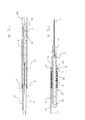
- Fig. 1 is an isometric depiction of the Peripheral Intravenous Safety Catheter with Quick, Painless Puncture System (PISCQPPS).
- the catheter (1) surrounds the cannula (7).
- the cannula-catheter assemblage is attached to the catheter holder (3), which is located in the trigger holder (5) from which the triggers (4) protrude.
- the bellows section is located inside the case (9).
- the PISCQPPS therefore consists of 9 parts, as shown in the exploded view in Fig. 2 .
- the parts that make up the PISCQPPS are: (1) the catheter; (2) the catheter holder; (3) and (4) the trigger guard, (5) the trigger-guard case; (6) the tube that holds the catheter; (7) the cannula; (8) the cannula holder; (9) the case; (10) the bellows; (11) the spring; (12) the filter holder; and (13) the filter.
- the PISCQPPS can be carried inside its cap (14), which is designed to protect it during transportation and prevent the needle from touching anything until it is used.
- the PISCQPPS is bared ready for perforation.
- the case (9) and the triggers (3) and (4) are pressed simultaneously, as shown in Fig. 3 , thus activating the painless puncture system.
- the painless puncture system shown in Fig. 5 , is located inside the case (9), being composed of (1) the catheter; (2) the catheter case; (3) and (4) the trigger guard; (5) the guard holder; (6) the catheter-holding tube; (7) the cannula; (8) the cannula holder; (11) the spring; (12) the filter holder; and (13) the filter.
- triggers (3) and (4) are activated, they move inside the catch holder (5), bringing the bevel of the catheter holder (6) into line with the trigger slit.
- the highspeed spring (11) action frees the catheter (1), the catheter holder (2), the catheter-holding tube (6), the cannula (7), the cannula holder (8), the filter holder (12) and the filter (13) as a single body.
- the said PISCQPPS is placed in its final position following approved medical procedures, being slightly separated from the catheter holder (2), and, using the cannula for support, the catheter is inserted until it reaches its final position, at which point the safety system shown in Figs. 6 and 7 -in which the case (9), the cannula holder (8), the cannula (7) and the bellows (10) spring into action simultaneously- is triggered.
- the spring (11) is inside this system, but does not play an active role until the catheter holder (2) and the catheter-holding tube (4), which are conjoined like a single piece, are held down and the case (9) is pulled down, activating the bellows and pulling the cannula holder (8) and the cannula (7) backwards, so that the PISCQPPS adopts the position shown in Figs. 6 and 7 , with the case (9), the cannula holder (8), the cannula (7) and the bellows (10) moving simultaneously.
- the spring (11) is inside this system but does not play an active role, only starting to function when the catheter holder (2) and the catheter-holder tube (4),conjoined as if they were a single entity, are held down and the said case (9) is pulled so as to activate the bellows and pull the cannula holder (8) and the cannula (7) backwards, with the result that the PISCQPPS adopts the position shown Fig. 12 .
- the cannula (7) which is attached to the cannula holder, is protected inside the catheter-holder tube (6) and the bellows (10), which, when the process is finished, is fully extended so as to form a protective chamber.
- the firing system is basically activated by moving triggers (3) and (4) inside the trigger holder (5) that is shown in detail in Fig. 8 .
- This is a simple, innovative triggering system (See Fig. 9 ) whereby two pieces, each with a sloping contact surface, can slide against each other so as to create an open slot through which the mechanism that is to be freed can pass.
- the outer surface of each of the aforesaid pieces has a ridge that prevents the system from being activated accidentally, with the said system only being set in motion when enough pressure is applied to move it all the way, as shown in Fig. 9b .
- each half of the trigger guard has various pairs of legs (96). These legs (96) each have four surfaces - i.e. the one that forms the transversal cavity, the outer front one the inner front one, and the side one- and, rather than covering the whole area of the upper surfaces of the sides, they cover half of the upper side of each half of the trigger guard.
- the shapes of the five exposed faces of the legs come together to form a channel or slit (91 and 90) and the corresponding slots in front of it, so as to form certain limits with jutting out parts (93) and slits (90) that keep the trigger guard in the same position, without any change, unless a force of a certain magnitude is applied at a certain point and in a certain direction so as to activate the two halves of the said trigger guard.
- each half of the trigger guard On the inner surface of legs 96, 98 and 99 of each half of the trigger guard are slits 95 and 94, which move limit 92, and its counterpart on the other leg, into the triggering position. Limit 93 and its counterpart on the other leg of the same half of the trigger guard move into place when the trigger catch in slot 100 is activated along with its counterpart on the other leg located on the same half.
Abstract
Description
- This invention is related to the hospital-equipment manufacturing industry, and more specifically to the industry that manufactures instruments for venous puncturing and canalization. Even more specifically, it is linked to the industry that manufactures instruments for quick puncturing and canalization that reduce or eliminate pain.
- As mentioned by Rivera, et al. [1], intravenous (IV) therapy springs from the need to transfer blood from one human being to another, and dates from around 1492. Currently, catheter-insertion devices are common; when a catheter is inserted in a patient in order to administer a liquid intravenously, a disposable needle is used that passes through a catheter to puncture a vein and enable the probe to enter. Subsequently, the needle is withdrawn, leaving the catheter in place so that it can be connected to an intravenous bag or bottle, or to a tip for later use.
- There is epidemiological evidence, worldwide, that the main unease regarding mishaps in the use of perforating instruments and their later disposal as a part of infectious hospital waste relates to possible transmission of the AIDS virus and, more often, of the hepatitis-B and hepatitis-C viruses, due to lesions caused by needles that are contaminated with human blood. Hence, new products have been designed incorporating special coverings for the needle, or mechanisms for withdrawing the latter into a protective chamber. Such devices are, for example, described in
US patents numbers 4.747.831 ,4.828.548 ,5.129.884 ,5.501.675 ,5.817.058 ,5.989.220 ,7.771.394 and7.740.615 . Many of the devices described in the aforesaid patents consist of numerous parts that substantially drive up their manufacturing costs, as well as hampering the user's ability to feel whether the needle is correctly inserted into the patient. Other devices need to be operated with two hands, or their needles are liable to become prematurely withdrawn during transportation, storage or handling. - Furthermore, studies [2] show that the pain associated with the penetration of the skin by the needle is caused by friction and the thrust load that occurs when the needle is inserted. Davis [3] states that there is only one relevant factor that affects the forces that occur when the skin is penetrated - i.e. the ratio between the force of the insertion and the surface area of the point. It should be added that pain -which is a mechanism for protecting the organism and occurs whenever tissue is being damaged, making the individual react in order to eliminate the painful stimulus- has been divided into two types - fast and slow. The former type is produced within around 0.1 seconds of receiving the stimulus, also being described as penetrating, stabbing, sharp, acute, electric, etc. For example, such pain is felt when a needle is stuck into the skin or when the latter is cut with a knife, though no quick, pulsing pain is felt in most of the deeper body tissues.
- Since we know that venous canalization is currently carried out manually in patients, the staff who perform this operation must be very experienced and employ a special, highly polished technique in order to avoid hurting and harming the patient when they insert the needle into the vein. However, despite such experience and skill, the patient can sometimes be subjected to pain and multiple skin punctures when an appropriate vein cannot be found or due to bad insertion techniques. Some attempts have been made to produce devices aimed at reducing or doing away with pain by improving injection techniques or eliminating the need for such specialized techniques - e.g. the Auxiliary Device for Painless Venous Perforation (Spanish initials: DAPV), patented in Cuba in 1966, and the Device for Procuring Painless Peripheral Venous Catheterization (Mexican patent number:
247215 - The first of these devices, the DAPV, is a type of "crossbow" in which a plastic syringe is mounted along with its plunger and needle, which is shot into the selected vein by means of a mechanism that is triggered one single time by the technician carrying out the process.
- The second of them, the Device for Procuring Painless Peripheral Venous Catheterization, consists of a mounting framework for the mechanisms for supporting, attaching and triggering catheters or hypodermic needles, with both patents permitting the uncontrolled shooting of the said catheters or hypodermic needles.
- As can be inferred from this text, an intravenous catheter device must have certain qualities, including the ability to: (a) reduce or eliminate pain; (b) reduce the chances of multiple skin punctures; (c) reduce the need for special injection skills and experience, in addition to which it must: (d) be fitted with a safety system and (e) be easy to use, and these are the features that this invention claims to have.
- The main aim of the invention is to provide a device that permits fast, pain-reducing perforation and canalization.
- Another of its aims is to reduce human error at the moment of perforation, thus avoiding the need for multiple perforations and reducing the risk of passing all the way through the vein.
- Yet another aim is to reduce the need for experienced catheterizing staff and diminish the risk of contamination with body fluids, in addition to all the other aims that will become clear upon perusal of this text and the illustrative, though not exhaustive, drawings that accompany it.
- This invention consists of a system for inserting intravenous catheters, and above all of a system for doing this quickly in a way that will reduce or do away with pain by means of a retractable cannula mounted in a manually operated bellows-type mechanism to prevent repeated use and incorrect perforation and allow for safe disposal.
- The system in question is a double one, one of whose components permits fast penetration so as to prevent pain and avoid stretching of the vein during cutting. A second component contains a manual safety mechanism that enables the contaminated cannula to be gathered inside a protective chamber so as to prevent the user or other people from coming into contact with it after use, thus preventing accidental perforation and the transmission of diseases.
- Furthermore, the fast-perforation system reduces the number of incidences of repeat perforation due to inexperience, since the system itself does the perforation, also reducing the fear of a vein being perforated all the way through or severed, by controlling the depth of penetration.
- Likewise, the retractile system assures that there is no contact whatsoever with the cannula after placement of the catheter, allowing the said cannula to be removed to a safe distance inside the security system.
- The propulsion mechanism consists of a spring that passes through a cannula-carrying device inside a catheter holder that is itself supported by a safety device to prevent accidental triggering. When the device is loaded, these elements are stored inside a case and the trigger-guard mechanisms, which stick out through some slits in the said case, keep them pressed down. When the two halves of the guards are pressed in towards the middle, two things happen: first two half-slits come together to form a single slit, through which part of the catheter-holding tube passes, reaching a given length depending on how far the spring is stretched, upon which the spring, being liberated by the movement of the two halves of the trigger-guard, pushes the cannula holder, which, in turn, pushes the catheter-holding tube. This movement enables the vein to be perforated very fast, and, also, when the catheter-holding tube is liberated, the safety-catch holder is also freed, which, after perforation, can be deployed to cover the cannula holder and part of the cannula, since the end of the said cannula is normally covered by the catheter-holding tube.
- The bellows mechanism is stretched, in order to cover the part of the cannula that came into contact with human tissue and/or blood, by holding the cannula holder apart from the cannula and pulling the socket towards the end opposite to the one where the cannula holder is located.
-
-
Fig. 1 is an isometric depiction of the Peripheral Intravenous Safety Catheter with Quick, Painless Puncture System (initials: PISCQPPS). -
Fig. 2 is an exploded diagram showing the parts that make up the Peripheral Intravenous Safety Catheter with Quick, Painless Puncture System. -
Fig. 3 is a detailed drawing of the protective cap of the PISCQPPS. -
Fig. 4 shows the firing system in detail. -
Fig. 5 is a drawing of the painless puncture system, showing its parts, how they interact with each other, and where they are located vis-à-vis each other. -
Fig. 6 is an A-A section showing the safety system. -
Fig. 7 is a B-B section of the safety system. -
Fig. 8 shows the Peripheral Intravenous Safety Catheter with Quick, Painless Puncture System, depicting the position of the safety guard in detail. -
Fig. 9 shows the trigger before it is activated. -
Fig. 10 shows the trigger guard after activation. -
Fig. 11 shows the position of the parts after the trigger has been activated. -
Fig. 12 shows how the bellows section is elongated to cover the cannula and prevent the user from having any contact with it. - This detailed description is supported by illustrations of the preferred variant of the invention.
-
Fig. 1 is an isometric depiction of the Peripheral Intravenous Safety Catheter with Quick, Painless Puncture System (PISCQPPS).The catheter (1) surrounds the cannula (7). The cannula-catheter assemblage is attached to the catheter holder (3), which is located in the trigger holder (5) from which the triggers (4) protrude. The bellows section is located inside the case (9). - The PISCQPPS therefore consists of 9 parts, as shown in the exploded view in
Fig. 2 . As can be seen from the saidFig. 2 , the parts that make up the PISCQPPS are: (1) the catheter; (2) the catheter holder; (3) and (4) the trigger guard, (5) the trigger-guard case; (6) the tube that holds the catheter; (7) the cannula; (8) the cannula holder; (9) the case; (10) the bellows; (11) the spring; (12) the filter holder; and (13) the filter. - As shown in Fig. 14, the PISCQPPS can be carried inside its cap (14), which is designed to protect it during transportation and prevent the needle from touching anything until it is used. When the top is removed, the PISCQPPS is bared ready for perforation. Once the said PISCQPPS is in the right position for perforation, the case (9) and the triggers (3) and (4) are pressed simultaneously, as shown in
Fig. 3 , thus activating the painless puncture system. - The painless puncture system, shown in
Fig. 5 , is located inside the case (9), being composed of (1) the catheter; (2) the catheter case; (3) and (4) the trigger guard; (5) the guard holder; (6) the catheter-holding tube; (7) the cannula; (8) the cannula holder; (11) the spring; (12) the filter holder; and (13) the filter. When triggers (3) and (4) are activated, they move inside the catch holder (5), bringing the bevel of the catheter holder (6) into line with the trigger slit. When the said slit and the bevel are aligned, the highspeed spring (11) action frees the catheter (1), the catheter holder (2), the catheter-holding tube (6), the cannula (7), the cannula holder (8), the filter holder (12) and the filter (13) as a single body. - These parts move a distance that is predetermined based on experience and the average thicknesses of the different skin layers, penetrating the skin and vein proper.
- Once the catheter (1) has penetrated the skin and vein, with the parts of the PISCQPPS being in the positions shown in
Fig. 11 , the said PISCQPPS is placed in its final position following approved medical procedures, being slightly separated from the catheter holder (2), and, using the cannula for support, the catheter is inserted until it reaches its final position, at which point the safety system shown inFigs. 6 and 7 -in which the case (9), the cannula holder (8), the cannula (7) and the bellows (10) spring into action simultaneously- is triggered. The spring (11) is inside this system, but does not play an active role until the catheter holder (2) and the catheter-holding tube (4), which are conjoined like a single piece, are held down and the case (9) is pulled down, activating the bellows and pulling the cannula holder (8) and the cannula (7) backwards, so that the PISCQPPS adopts the position shown inFigs. 6 and 7 , with the case (9), the cannula holder (8), the cannula (7) and the bellows (10) moving simultaneously. The spring (11) is inside this system but does not play an active role, only starting to function when the catheter holder (2) and the catheter-holder tube (4),conjoined as if they were a single entity, are held down and the said case (9) is pulled so as to activate the bellows and pull the cannula holder (8) and the cannula (7) backwards, with the result that the PISCQPPS adopts the position shownFig. 12 . - In the course of this process, the cannula (7), which is attached to the cannula holder, is protected inside the catheter-holder tube (6) and the bellows (10), which, when the process is finished, is fully extended so as to form a protective chamber. Once the cannula has been thus protected, it can be subjected to hazardous waste disposal procedures without risk of any accidental contact with it occurring.
- The firing system is basically activated by moving triggers (3) and (4) inside the trigger holder (5) that is shown in detail in
Fig. 8 . This is a simple, innovative triggering system (SeeFig. 9 ) whereby two pieces, each with a sloping contact surface, can slide against each other so as to create an open slot through which the mechanism that is to be freed can pass. The outer surface of each of the aforesaid pieces has a ridge that prevents the system from being activated accidentally, with the said system only being set in motion when enough pressure is applied to move it all the way, as shown inFig. 9b . - In other words, the two halves of the trigger guard (3 and 4) are separate pieces with hollow semicircular channels that join together to form a complete transversal cavity inside which the distal tip of the catheter-holder tube (6) will be housed with its projecting ridge (20), which, when the two halves of the trigger guard are displaced, jams against one of the surfaces of one of the said halves. At one of its ends, each half of the trigger guard has various pairs of legs (96). These legs (96) each have four surfaces - i.e. the one that forms the transversal cavity, the outer front one the inner front one, and the side one- and, rather than covering the whole area of the upper surfaces of the sides, they cover half of the upper side of each half of the trigger guard. The shapes of the five exposed faces of the legs come together to form a channel or slit (91 and 90) and the corresponding slots in front of it, so as to form certain limits with jutting out parts (93) and slits (90) that keep the trigger guard in the same position, without any change, unless a force of a certain magnitude is applied at a certain point and in a certain direction so as to activate the two halves of the said trigger guard.
- On the inner surface of
legs slits limit 92, and its counterpart on the other leg, into the triggering position.Limit 93 and its counterpart on the other leg of the same half of the trigger guard move into place when the trigger catch inslot 100 is activated along with its counterpart on the other leg located on the same half. -
- [1.] A. M. Rivera , K. W. Strauss , A. Van Zundert, and E. Mortier, The history of peripheral intravenous catheters : How little plastic tubes revolutionized medicine, Acta Anaesth. Belg., 2005, 56, 271-282
- [2.] Hiroyuki Kataoka," Measurement of the tip and friction force acting on a needle during penetration", National Institute of Advanced Industrial Science and Technology, MICCAI '02 Proceedings of the 5th International Conference on Medical Image Computing and Computer-Assisted Intervention-Part I, 2002
- [3.] Davis, S. P., "Hollow microneedles for molecular transport across skin", Ph.D. Thesis, Georgia Institute of Technology, 2003.
- The invention has been described in sufficient detail to enable anybody with a modicum of knowledge on the topic to duplicate the results mentioned above. However, though any person skilled in the technique pertaining to the invention described here would be able to make modifications that are not described in this application, nonetheless, if the information that is set forth in the following claims is necessary in order to apply the said modifications to a given structure, or to the process for manufacturing the said structure, then the structure in question must be deemed to form a part of the invention here described.
Claims (6)
- Since it has been described in functional detail, claim is laid to ownership of the invention described below: 1.- Peripheral Intravenous Safety Catheter with Quick, Painless Puncture System (PISCQPPS), characterized as consisting of: a catheter (1) connected to the catheter holder (2) that is located in the trigger holder (5) that also holds the trigger guard, made up of two halves (3) and (4); the section consisting of the catheter (1) and the catheter-holder is connected, via the said catheter holder, to the catheter-holder tube (6); the cannula (7) is located inside the catheter (1), the catheter holder (2) and the catheter-holder tube (6); at the tip opposite to the free one, the cannula is attached to the cannula holder (8), while most of the PISCQPPS is located inside the case (9); between the case (9) and the cannula holder (8)is the bellows (10), while a spring (11) is located at the distal end of the cannula holder in order to propel it at high speed when the cannula-holder spring is released; before being activated, the halves of catches (3) and (4) have been moved along in such a way that the halves of the front and back slits do not match each other and, when the trigger guard has not been activated, the longitudinal ridges of the catheter-holder tube are pressed up against the corresponding areas of the one of the halves of the guard.
- As asserted in the above claim, the Peripheral Intravenous Safety Catheter with Quick, Painless Puncture System (PISCQPPS, which is also distinguished by the fact that both halves of the trigger guard have a pair of legs (96 and 98), of which the ones on the side, the ones on the outside and the contact ones have four faces, while the central ones bear half of the slits that allow the longitudinal ridges (20) of the catheter-holder tube (6) to pass through when the trigger guard is activated, while the slanted contact surfaces have slits and limits that allow the trigger guard to be held in place unless a certain amount of force, with certain point of leverage and a certain orientation, is exercised in order to slide the contact surfaces to a point where the ridges or limits meet the corresponding slits in the firing position.
- Peripheral Intravenous Safety Catheter with Quick, Painless Puncture System (PISCQPPS), which, as asserted in claims 1 and 2, is also distinguished by the fact that it has a filter carrier (12), with a filter (13) at the entrance to the catheter to prevent extraneous materials from entering the said catheter.
- Peripheral Intravenous Safety Catheter with Quick, Painless Puncture System (PISCQPPS), which, as asserted in claims 1 and 2, is distinguished by the fact that it also has a protective cap or sheath (14) to protect both it and those who might come into contact with it during transportation.
- Peripheral Intravenous Safety Catheter with Quick, Painless Puncture System (PISCQPPS), which, as asserted in each of claims 1-4, is distinguished by the fact that part of the catheter (1), the catheter holder (2), the trigger guard (3 and 4), the trigger-guard holder (5), the catheter-holder tube (6), the cannula (7), the cannula holder (8), the spring (11), the filter holder (12) and the filter (13) are all located inside the case (9).
- Peripheral Intravenous Safety Catheter with Quick, Painless Puncture System (PISCQPPS), which, as asserted in each of claims 1-5, is distinguished by its possession of a safety system in which the case (9), the cannula-holder tube (8), the cannula (7) and the bellows (10) all work simultaneously.
Applications Claiming Priority (1)
| Application Number | Priority Date | Filing Date | Title |
|---|---|---|---|
| MX2011013382A MX2011013382A (en) | 2011-12-12 | 2011-12-12 | Safety peripheral intravenous catheter having a quick, painless puncture system. |
Publications (2)
| Publication Number | Publication Date |
|---|---|
| EP2604307A1 true EP2604307A1 (en) | 2013-06-19 |
| EP2604307B1 EP2604307B1 (en) | 2019-10-23 |
Family
ID=47227734
Family Applications (1)
| Application Number | Title | Priority Date | Filing Date |
|---|---|---|---|
| EP12382423.7A Not-in-force EP2604307B1 (en) | 2011-12-12 | 2012-10-31 | Peripheral intravenous safety catheter with quick, painless puncture system |
Country Status (5)
| Country | Link |
|---|---|
| US (1) | US8585644B2 (en) |
| EP (1) | EP2604307B1 (en) |
| BR (1) | BR102012031692A2 (en) |
| MX (1) | MX2011013382A (en) |
| WO (1) | WO2013089541A1 (en) |
Families Citing this family (22)
| Publication number | Priority date | Publication date | Assignee | Title |
|---|---|---|---|---|
| US7655004B2 (en) | 2007-02-15 | 2010-02-02 | Ethicon Endo-Surgery, Inc. | Electroporation ablation apparatus, system, and method |
| US8888792B2 (en) | 2008-07-14 | 2014-11-18 | Ethicon Endo-Surgery, Inc. | Tissue apposition clip application devices and methods |
| US8157834B2 (en) | 2008-11-25 | 2012-04-17 | Ethicon Endo-Surgery, Inc. | Rotational coupling device for surgical instrument with flexible actuators |
| US8323249B2 (en) | 2009-08-14 | 2012-12-04 | The Regents Of The University Of Michigan | Integrated vascular delivery system |
| US20110098704A1 (en) | 2009-10-28 | 2011-04-28 | Ethicon Endo-Surgery, Inc. | Electrical ablation devices |
| WO2011146772A1 (en) | 2010-05-19 | 2011-11-24 | Tangent Medical Technologies Llc | Safety needle system operable with a medical device |
| US8771230B2 (en) | 2010-05-19 | 2014-07-08 | Tangent Medical Technologies, Llc | Integrated vascular delivery system |
| US9233241B2 (en) | 2011-02-28 | 2016-01-12 | Ethicon Endo-Surgery, Inc. | Electrical ablation devices and methods |
| US9427255B2 (en) | 2012-05-14 | 2016-08-30 | Ethicon Endo-Surgery, Inc. | Apparatus for introducing a steerable camera assembly into a patient |
| US9545290B2 (en) * | 2012-07-30 | 2017-01-17 | Ethicon Endo-Surgery, Inc. | Needle probe guide |
| US9277957B2 (en) | 2012-08-15 | 2016-03-08 | Ethicon Endo-Surgery, Inc. | Electrosurgical devices and methods |
| MX2013001219A (en) | 2013-01-30 | 2014-07-30 | Equipos Médicos Vizcarra S A | Closed peripheral intravenous catheter with safety system cpivcss. |
| US10098527B2 (en) | 2013-02-27 | 2018-10-16 | Ethidcon Endo-Surgery, Inc. | System for performing a minimally invasive surgical procedure |
| WO2015115315A1 (en) * | 2014-01-29 | 2015-08-06 | テルモ株式会社 | Catheter assembly |
| CA2937744C (en) | 2014-02-04 | 2022-08-09 | Icu Medical, Inc. | Self-priming systems and methods |
| CN107921240B (en) * | 2015-05-08 | 2020-11-17 | 洪志华 | Manual vein indwelling needle set |
| EP3307353A4 (en) * | 2015-06-15 | 2019-03-13 | The University Of Sydney | Insertion system and method |
| USD865956S1 (en) | 2017-01-25 | 2019-11-05 | Becton, Dickinson And Company | Catheter assembly |
| USD858755S1 (en) * | 2017-01-25 | 2019-09-03 | Becton, Dickinson And Company | Catheter assembly and needle cover |
| USD859651S1 (en) * | 2017-01-25 | 2019-09-10 | Becton, Dickinson And Company | Catheter hub |
| CN111658975B (en) * | 2020-04-28 | 2021-12-31 | 温州医科大学附属第二医院、温州医科大学附属育英儿童医院 | Step-by-step esophagus dilating saccule |
| KR102480888B1 (en) * | 2022-09-15 | 2022-12-26 | 주식회사 덕우메디칼 | safety catheter assembly |
Citations (11)
| Publication number | Priority date | Publication date | Assignee | Title |
|---|---|---|---|---|
| US4747831A (en) | 1987-04-29 | 1988-05-31 | Phase Medical, Inc. | Cannula insertion set with safety retracting needle |
| US4828548A (en) | 1987-03-16 | 1989-05-09 | Walter Gregory W | Safety catheter |
| US5129884A (en) | 1990-01-16 | 1992-07-14 | Dysarz Edward D | Trap in barrel one handed retracted intervenous catheter device |
| US5320609A (en) * | 1992-12-07 | 1994-06-14 | Habley Medical Technology Corporation | Automatic pharmaceutical dispensing syringe |
| US5501675A (en) | 1994-12-27 | 1996-03-26 | Becton, Dickinson And Company | Safety catheter assembly having safety stop push button |
| US5681291A (en) * | 1992-11-19 | 1997-10-28 | Tebro S.A. | Disposable auto-injector for prefilled syringes |
| US5695474A (en) | 1995-09-18 | 1997-12-09 | Becton Dickinson And Company | Needle shield with collapsible cover |
| US5817058A (en) | 1996-12-23 | 1998-10-06 | Shaw; Thomas J. | Retractable catheter introducer structure |
| US5989220A (en) | 1998-05-26 | 1999-11-23 | Retractable Technologies Inc. | Self-retracting IV catheter introducer |
| US7740615B2 (en) | 2001-10-26 | 2010-06-22 | Retractable Technologies, Inc. | IV catheter introducer with retractable needle—continuation |
| US7771394B2 (en) | 2006-06-16 | 2010-08-10 | Ming-Jeng Shue | Intravenous catheter introducing device |
Family Cites Families (8)
| Publication number | Priority date | Publication date | Assignee | Title |
|---|---|---|---|---|
| FR2684006B1 (en) * | 1991-11-27 | 1998-01-09 | Sarl Gestra | PUNCTURE NEEDLE FOR PERIPHERAL CATHETER. |
| US5501674A (en) * | 1994-03-07 | 1996-03-26 | Medrad, Inc. | Intravenous catheter with needle cover and blood collection tube |
| US6620136B1 (en) * | 1999-02-18 | 2003-09-16 | Medsafe Technologies, Llc | Retractable I-V catheter placement device |
| TWI238070B (en) * | 2003-11-07 | 2005-08-21 | Ming-Jeng Shiu | Medical appliances |
| JP2005152282A (en) * | 2003-11-26 | 2005-06-16 | Jms Co Ltd | Puncturing instrument |
| JP2007521918A (en) * | 2004-02-13 | 2007-08-09 | スミス・メディカル・エイエスディ・インコーポレーテッド | Needle tip protector |
| TW200822941A (en) * | 2006-11-30 | 2008-06-01 | ming-zheng Xu | Medical instrument having withdrawing force |
| US20110306933A1 (en) * | 2010-06-11 | 2011-12-15 | Ilija Djordjevic | Safety cannula with automatic retractable needle |
-
2011
- 2011-12-12 MX MX2011013382A patent/MX2011013382A/en active IP Right Grant
- 2011-12-13 WO PCT/MX2011/000157 patent/WO2013089541A1/en active Application Filing
-
2012
- 2012-07-27 US US13/560,434 patent/US8585644B2/en not_active Expired - Fee Related
- 2012-10-31 EP EP12382423.7A patent/EP2604307B1/en not_active Not-in-force
- 2012-12-12 BR BR102012031692A patent/BR102012031692A2/en not_active IP Right Cessation
Patent Citations (11)
| Publication number | Priority date | Publication date | Assignee | Title |
|---|---|---|---|---|
| US4828548A (en) | 1987-03-16 | 1989-05-09 | Walter Gregory W | Safety catheter |
| US4747831A (en) | 1987-04-29 | 1988-05-31 | Phase Medical, Inc. | Cannula insertion set with safety retracting needle |
| US5129884A (en) | 1990-01-16 | 1992-07-14 | Dysarz Edward D | Trap in barrel one handed retracted intervenous catheter device |
| US5681291A (en) * | 1992-11-19 | 1997-10-28 | Tebro S.A. | Disposable auto-injector for prefilled syringes |
| US5320609A (en) * | 1992-12-07 | 1994-06-14 | Habley Medical Technology Corporation | Automatic pharmaceutical dispensing syringe |
| US5501675A (en) | 1994-12-27 | 1996-03-26 | Becton, Dickinson And Company | Safety catheter assembly having safety stop push button |
| US5695474A (en) | 1995-09-18 | 1997-12-09 | Becton Dickinson And Company | Needle shield with collapsible cover |
| US5817058A (en) | 1996-12-23 | 1998-10-06 | Shaw; Thomas J. | Retractable catheter introducer structure |
| US5989220A (en) | 1998-05-26 | 1999-11-23 | Retractable Technologies Inc. | Self-retracting IV catheter introducer |
| US7740615B2 (en) | 2001-10-26 | 2010-06-22 | Retractable Technologies, Inc. | IV catheter introducer with retractable needle—continuation |
| US7771394B2 (en) | 2006-06-16 | 2010-08-10 | Ming-Jeng Shue | Intravenous catheter introducing device |
Non-Patent Citations (3)
| Title |
|---|
| A. M. RIVERA; K. W. STRAUSS; A. VAN ZUNDERT; E. MORTIER: "The history of peripheral intravenous catheters : How little plastic tubes revolutionized medicine", ACTA ANAESTH. BELG., vol. 56, 2005, pages 271 - 282 |
| DAVIS, S. P.: "Ph.D. Thesis", 2003, GEORGIA INSTITUTE OF TECHNOLOGY, article "Hollow microneedles for molecular transport across skin" |
| HIROYUKI KATAOKA: "Measurement of the tip and friction force acting on a needle during penetration", NATIONAL INSTITUTE OF ADVANCED INDUSTRIAL SCIENCE AND TECHNOLOGY, MICCAI '02 PROCEEDINGS OF THE 5TH INTERNATIONAL CONFERENCE ON MEDICAL IMAGE COMPUTING AND COMPUTER-ASSISTED INTERVENTION-PART I, 2002 |
Also Published As
| Publication number | Publication date |
|---|---|
| WO2013089541A1 (en) | 2013-06-20 |
| US8585644B2 (en) | 2013-11-19 |
| MX2011013382A (en) | 2013-06-20 |
| BR102012031692A2 (en) | 2015-10-20 |
| US20130150784A1 (en) | 2013-06-13 |
| EP2604307B1 (en) | 2019-10-23 |
Similar Documents
| Publication | Publication Date | Title |
|---|---|---|
| US8585644B2 (en) | Peripheral intravenous safety catheter with quick, painless puncture system | |
| US11103170B2 (en) | Flash activated passive shielding needle assembly | |
| US4929237A (en) | Hypodermic needle protection device | |
| US20180256856A1 (en) | Peripheral intravenous catheter with bellows-type passive safety system ivcbts | |
| ES2290765T3 (en) | SAFETY PROTECTION DEVICE OF A NEEDLE. | |
| EP2399624B1 (en) | Device for inserting a soft member into the tissue of the body of a patient | |
| CZ296796B6 (en) | Medical needle encapsulating safety apparatus | |
| NZ286625A (en) | Catheter insertion device: lever and release clip releasably locks hub to housing | |
| JP2011520553A (en) | Device for deflecting the needle safely | |
| US6616638B2 (en) | Hypodermic needle cap and sharps protective cap ejector | |
| AU3708902A (en) | Passively activated safely needle | |
| JP2012531964A (en) | Safety catheter | |
| WO2010061405A2 (en) | Safely disposable i.v. cannula device | |
| JP2013538617A (en) | Safety catheter | |
| US5069341A (en) | Disposable single-use drip-feed device with a cover for the needle after use | |
| JP2015534894A (en) | Safety blood collection device activated by a passive dual drive member | |
| JPH04180772A (en) | Needle for medical treatment | |
| EP2870977B1 (en) | Extraction device for collecting blood samples, including a catheter and a safety system | |
| TW201902526A (en) | Protective sleeve for syringe | |
| JP3576765B2 (en) | Indwelling needle assembly | |
| US20140121694A1 (en) | Trocar dispenser and grip receiver safety system | |
| CN219423453U (en) | Prevent acupuncture protective sheath | |
| US20220218908A1 (en) | Shield assembly for syringe | |
| WO2024015430A1 (en) | Iv catheter device | |
| EP2399623A1 (en) | Device for inserting an insertion member into the tissue of the body of a patient |
Legal Events
| Date | Code | Title | Description |
|---|---|---|---|
| PUAI | Public reference made under article 153(3) epc to a published international application that has entered the european phase |
Free format text: ORIGINAL CODE: 0009012 |
|
| AK | Designated contracting states |
Kind code of ref document: A1 Designated state(s): AL AT BE BG CH CY CZ DE DK EE ES FI FR GB GR HR HU IE IS IT LI LT LU LV MC MK MT NL NO PL PT RO RS SE SI SK SM TR |
|
| AX | Request for extension of the european patent |
Extension state: BA ME |
|
| 17P | Request for examination filed |
Effective date: 20131210 |
|
| GRAP | Despatch of communication of intention to grant a patent |
Free format text: ORIGINAL CODE: EPIDOSNIGR1 |
|
| STAA | Information on the status of an ep patent application or granted ep patent |
Free format text: STATUS: GRANT OF PATENT IS INTENDED |
|
| INTG | Intention to grant announced |
Effective date: 20190704 |
|
| GRAS | Grant fee paid |
Free format text: ORIGINAL CODE: EPIDOSNIGR3 |
|
| GRAA | (expected) grant |
Free format text: ORIGINAL CODE: 0009210 |
|
| STAA | Information on the status of an ep patent application or granted ep patent |
Free format text: STATUS: THE PATENT HAS BEEN GRANTED |
|
| AK | Designated contracting states |
Kind code of ref document: B1 Designated state(s): AL AT BE BG CH CY CZ DE DK EE ES FI FR GB GR HR HU IE IS IT LI LT LU LV MC MK MT NL NO PL PT RO RS SE SI SK SM TR |
|
| REG | Reference to a national code |
Ref country code: GB Ref legal event code: FG4D |
|
| REG | Reference to a national code |
Ref country code: CH Ref legal event code: EP |
|
| REG | Reference to a national code |
Ref country code: IE Ref legal event code: FG4D |
|
| REG | Reference to a national code |
Ref country code: DE Ref legal event code: R096 Ref document number: 602012065049 Country of ref document: DE |
|
| REG | Reference to a national code |
Ref country code: AT Ref legal event code: REF Ref document number: 1192989 Country of ref document: AT Kind code of ref document: T Effective date: 20191115 |
|
| REG | Reference to a national code |
Ref country code: NL Ref legal event code: MP Effective date: 20191023 |
|
| REG | Reference to a national code |
Ref country code: LT Ref legal event code: MG4D |
|
| PG25 | Lapsed in a contracting state [announced via postgrant information from national office to epo] |
Ref country code: FI Free format text: LAPSE BECAUSE OF FAILURE TO SUBMIT A TRANSLATION OF THE DESCRIPTION OR TO PAY THE FEE WITHIN THE PRESCRIBED TIME-LIMIT Effective date: 20191023 Ref country code: LT Free format text: LAPSE BECAUSE OF FAILURE TO SUBMIT A TRANSLATION OF THE DESCRIPTION OR TO PAY THE FEE WITHIN THE PRESCRIBED TIME-LIMIT Effective date: 20191023 Ref country code: PT Free format text: LAPSE BECAUSE OF FAILURE TO SUBMIT A TRANSLATION OF THE DESCRIPTION OR TO PAY THE FEE WITHIN THE PRESCRIBED TIME-LIMIT Effective date: 20200224 Ref country code: BG Free format text: LAPSE BECAUSE OF FAILURE TO SUBMIT A TRANSLATION OF THE DESCRIPTION OR TO PAY THE FEE WITHIN THE PRESCRIBED TIME-LIMIT Effective date: 20200123 Ref country code: PL Free format text: LAPSE BECAUSE OF FAILURE TO SUBMIT A TRANSLATION OF THE DESCRIPTION OR TO PAY THE FEE WITHIN THE PRESCRIBED TIME-LIMIT Effective date: 20191023 Ref country code: NO Free format text: LAPSE BECAUSE OF FAILURE TO SUBMIT A TRANSLATION OF THE DESCRIPTION OR TO PAY THE FEE WITHIN THE PRESCRIBED TIME-LIMIT Effective date: 20200123 Ref country code: GR Free format text: LAPSE BECAUSE OF FAILURE TO SUBMIT A TRANSLATION OF THE DESCRIPTION OR TO PAY THE FEE WITHIN THE PRESCRIBED TIME-LIMIT Effective date: 20200124 Ref country code: LV Free format text: LAPSE BECAUSE OF FAILURE TO SUBMIT A TRANSLATION OF THE DESCRIPTION OR TO PAY THE FEE WITHIN THE PRESCRIBED TIME-LIMIT Effective date: 20191023 Ref country code: SE Free format text: LAPSE BECAUSE OF FAILURE TO SUBMIT A TRANSLATION OF THE DESCRIPTION OR TO PAY THE FEE WITHIN THE PRESCRIBED TIME-LIMIT Effective date: 20191023 Ref country code: NL Free format text: LAPSE BECAUSE OF FAILURE TO SUBMIT A TRANSLATION OF THE DESCRIPTION OR TO PAY THE FEE WITHIN THE PRESCRIBED TIME-LIMIT Effective date: 20191023 Ref country code: ES Free format text: LAPSE BECAUSE OF FAILURE TO SUBMIT A TRANSLATION OF THE DESCRIPTION OR TO PAY THE FEE WITHIN THE PRESCRIBED TIME-LIMIT Effective date: 20191023 |
|
| REG | Reference to a national code |
Ref country code: DE Ref legal event code: R119 Ref document number: 602012065049 Country of ref document: DE |
|
| PG25 | Lapsed in a contracting state [announced via postgrant information from national office to epo] |
Ref country code: HR Free format text: LAPSE BECAUSE OF FAILURE TO SUBMIT A TRANSLATION OF THE DESCRIPTION OR TO PAY THE FEE WITHIN THE PRESCRIBED TIME-LIMIT Effective date: 20191023 Ref country code: IS Free format text: LAPSE BECAUSE OF FAILURE TO SUBMIT A TRANSLATION OF THE DESCRIPTION OR TO PAY THE FEE WITHIN THE PRESCRIBED TIME-LIMIT Effective date: 20200224 Ref country code: RS Free format text: LAPSE BECAUSE OF FAILURE TO SUBMIT A TRANSLATION OF THE DESCRIPTION OR TO PAY THE FEE WITHIN THE PRESCRIBED TIME-LIMIT Effective date: 20191023 |
|
| REG | Reference to a national code |
Ref country code: CH Ref legal event code: PL |
|
| PG25 | Lapsed in a contracting state [announced via postgrant information from national office to epo] |
Ref country code: AL Free format text: LAPSE BECAUSE OF FAILURE TO SUBMIT A TRANSLATION OF THE DESCRIPTION OR TO PAY THE FEE WITHIN THE PRESCRIBED TIME-LIMIT Effective date: 20191023 |
|
| PG2D | Information on lapse in contracting state deleted |
Ref country code: IS |
|
| PG25 | Lapsed in a contracting state [announced via postgrant information from national office to epo] |
Ref country code: IS Free format text: LAPSE BECAUSE OF FAILURE TO SUBMIT A TRANSLATION OF THE DESCRIPTION OR TO PAY THE FEE WITHIN THE PRESCRIBED TIME-LIMIT Effective date: 20200223 Ref country code: CH Free format text: LAPSE BECAUSE OF NON-PAYMENT OF DUE FEES Effective date: 20191031 Ref country code: LI Free format text: LAPSE BECAUSE OF NON-PAYMENT OF DUE FEES Effective date: 20191031 Ref country code: CZ Free format text: LAPSE BECAUSE OF FAILURE TO SUBMIT A TRANSLATION OF THE DESCRIPTION OR TO PAY THE FEE WITHIN THE PRESCRIBED TIME-LIMIT Effective date: 20191023 Ref country code: LU Free format text: LAPSE BECAUSE OF NON-PAYMENT OF DUE FEES Effective date: 20191031 Ref country code: MC Free format text: LAPSE BECAUSE OF FAILURE TO SUBMIT A TRANSLATION OF THE DESCRIPTION OR TO PAY THE FEE WITHIN THE PRESCRIBED TIME-LIMIT Effective date: 20191023 Ref country code: DK Free format text: LAPSE BECAUSE OF FAILURE TO SUBMIT A TRANSLATION OF THE DESCRIPTION OR TO PAY THE FEE WITHIN THE PRESCRIBED TIME-LIMIT Effective date: 20191023 Ref country code: EE Free format text: LAPSE BECAUSE OF FAILURE TO SUBMIT A TRANSLATION OF THE DESCRIPTION OR TO PAY THE FEE WITHIN THE PRESCRIBED TIME-LIMIT Effective date: 20191023 Ref country code: DE Free format text: LAPSE BECAUSE OF NON-PAYMENT OF DUE FEES Effective date: 20200501 Ref country code: RO Free format text: LAPSE BECAUSE OF FAILURE TO SUBMIT A TRANSLATION OF THE DESCRIPTION OR TO PAY THE FEE WITHIN THE PRESCRIBED TIME-LIMIT Effective date: 20191023 |
|
| REG | Reference to a national code |
Ref country code: BE Ref legal event code: MM Effective date: 20191031 |
|
| REG | Reference to a national code |
Ref country code: AT Ref legal event code: MK05 Ref document number: 1192989 Country of ref document: AT Kind code of ref document: T Effective date: 20191023 |
|
| PLBE | No opposition filed within time limit |
Free format text: ORIGINAL CODE: 0009261 |
|
| STAA | Information on the status of an ep patent application or granted ep patent |
Free format text: STATUS: NO OPPOSITION FILED WITHIN TIME LIMIT |
|
| PG25 | Lapsed in a contracting state [announced via postgrant information from national office to epo] |
Ref country code: BE Free format text: LAPSE BECAUSE OF NON-PAYMENT OF DUE FEES Effective date: 20191031 Ref country code: IT Free format text: LAPSE BECAUSE OF FAILURE TO SUBMIT A TRANSLATION OF THE DESCRIPTION OR TO PAY THE FEE WITHIN THE PRESCRIBED TIME-LIMIT Effective date: 20191023 Ref country code: SK Free format text: LAPSE BECAUSE OF FAILURE TO SUBMIT A TRANSLATION OF THE DESCRIPTION OR TO PAY THE FEE WITHIN THE PRESCRIBED TIME-LIMIT Effective date: 20191023 Ref country code: SM Free format text: LAPSE BECAUSE OF FAILURE TO SUBMIT A TRANSLATION OF THE DESCRIPTION OR TO PAY THE FEE WITHIN THE PRESCRIBED TIME-LIMIT Effective date: 20191023 |
|
| GBPC | Gb: european patent ceased through non-payment of renewal fee |
Effective date: 20200123 |
|
| 26N | No opposition filed |
Effective date: 20200724 |
|
| PG25 | Lapsed in a contracting state [announced via postgrant information from national office to epo] |
Ref country code: FR Free format text: LAPSE BECAUSE OF NON-PAYMENT OF DUE FEES Effective date: 20191223 Ref country code: IE Free format text: LAPSE BECAUSE OF NON-PAYMENT OF DUE FEES Effective date: 20191031 Ref country code: GB Free format text: LAPSE BECAUSE OF NON-PAYMENT OF DUE FEES Effective date: 20200123 |
|
| PG25 | Lapsed in a contracting state [announced via postgrant information from national office to epo] |
Ref country code: AT Free format text: LAPSE BECAUSE OF FAILURE TO SUBMIT A TRANSLATION OF THE DESCRIPTION OR TO PAY THE FEE WITHIN THE PRESCRIBED TIME-LIMIT Effective date: 20191023 Ref country code: SI Free format text: LAPSE BECAUSE OF FAILURE TO SUBMIT A TRANSLATION OF THE DESCRIPTION OR TO PAY THE FEE WITHIN THE PRESCRIBED TIME-LIMIT Effective date: 20191023 |
|
| PG25 | Lapsed in a contracting state [announced via postgrant information from national office to epo] |
Ref country code: CY Free format text: LAPSE BECAUSE OF FAILURE TO SUBMIT A TRANSLATION OF THE DESCRIPTION OR TO PAY THE FEE WITHIN THE PRESCRIBED TIME-LIMIT Effective date: 20191023 |
|
| PG25 | Lapsed in a contracting state [announced via postgrant information from national office to epo] |
Ref country code: MT Free format text: LAPSE BECAUSE OF FAILURE TO SUBMIT A TRANSLATION OF THE DESCRIPTION OR TO PAY THE FEE WITHIN THE PRESCRIBED TIME-LIMIT Effective date: 20191023 Ref country code: HU Free format text: LAPSE BECAUSE OF FAILURE TO SUBMIT A TRANSLATION OF THE DESCRIPTION OR TO PAY THE FEE WITHIN THE PRESCRIBED TIME-LIMIT; INVALID AB INITIO Effective date: 20121031 |
|
| PG25 | Lapsed in a contracting state [announced via postgrant information from national office to epo] |
Ref country code: TR Free format text: LAPSE BECAUSE OF FAILURE TO SUBMIT A TRANSLATION OF THE DESCRIPTION OR TO PAY THE FEE WITHIN THE PRESCRIBED TIME-LIMIT Effective date: 20191023 |
|
| PG25 | Lapsed in a contracting state [announced via postgrant information from national office to epo] |
Ref country code: MK Free format text: LAPSE BECAUSE OF FAILURE TO SUBMIT A TRANSLATION OF THE DESCRIPTION OR TO PAY THE FEE WITHIN THE PRESCRIBED TIME-LIMIT Effective date: 20191023 |