EP2606920A1 - Sluice device for inserting a catheter - Google Patents
Sluice device for inserting a catheter Download PDFInfo
- Publication number
- EP2606920A1 EP2606920A1 EP11075273.0A EP11075273A EP2606920A1 EP 2606920 A1 EP2606920 A1 EP 2606920A1 EP 11075273 A EP11075273 A EP 11075273A EP 2606920 A1 EP2606920 A1 EP 2606920A1
- Authority
- EP
- European Patent Office
- Prior art keywords
- lock
- catheter
- pump
- clamping
- clamping ring
- Prior art date
- Legal status (The legal status is an assumption and is not a legal conclusion. Google has not performed a legal analysis and makes no representation as to the accuracy of the status listed.)
- Withdrawn
Links
Images


Classifications
-
- A—HUMAN NECESSITIES
- A61—MEDICAL OR VETERINARY SCIENCE; HYGIENE
- A61M—DEVICES FOR INTRODUCING MEDIA INTO, OR ONTO, THE BODY; DEVICES FOR TRANSDUCING BODY MEDIA OR FOR TAKING MEDIA FROM THE BODY; DEVICES FOR PRODUCING OR ENDING SLEEP OR STUPOR
- A61M25/00—Catheters; Hollow probes
- A61M25/01—Introducing, guiding, advancing, emplacing or holding catheters
- A61M25/06—Body-piercing guide needles or the like
- A61M25/0662—Guide tubes
- A61M25/0668—Guide tubes splittable, tear apart
-
- A—HUMAN NECESSITIES
- A61—MEDICAL OR VETERINARY SCIENCE; HYGIENE
- A61M—DEVICES FOR INTRODUCING MEDIA INTO, OR ONTO, THE BODY; DEVICES FOR TRANSDUCING BODY MEDIA OR FOR TAKING MEDIA FROM THE BODY; DEVICES FOR PRODUCING OR ENDING SLEEP OR STUPOR
- A61M39/00—Tubes, tube connectors, tube couplings, valves, access sites or the like, specially adapted for medical use
- A61M39/02—Access sites
- A61M39/06—Haemostasis valves, i.e. gaskets sealing around a needle, catheter or the like, closing on removal thereof
- A61M39/0613—Haemostasis valves, i.e. gaskets sealing around a needle, catheter or the like, closing on removal thereof with means for adjusting the seal opening or pressure
-
- A—HUMAN NECESSITIES
- A61—MEDICAL OR VETERINARY SCIENCE; HYGIENE
- A61M—DEVICES FOR INTRODUCING MEDIA INTO, OR ONTO, THE BODY; DEVICES FOR TRANSDUCING BODY MEDIA OR FOR TAKING MEDIA FROM THE BODY; DEVICES FOR PRODUCING OR ENDING SLEEP OR STUPOR
- A61M60/00—Blood pumps; Devices for mechanical circulatory actuation; Balloon pumps for circulatory assistance
- A61M60/10—Location thereof with respect to the patient's body
- A61M60/122—Implantable pumps or pumping devices, i.e. the blood being pumped inside the patient's body
- A61M60/126—Implantable pumps or pumping devices, i.e. the blood being pumped inside the patient's body implantable via, into, inside, in line, branching on, or around a blood vessel
- A61M60/13—Implantable pumps or pumping devices, i.e. the blood being pumped inside the patient's body implantable via, into, inside, in line, branching on, or around a blood vessel by means of a catheter allowing explantation, e.g. catheter pumps temporarily introduced via the vascular system
-
- A—HUMAN NECESSITIES
- A61—MEDICAL OR VETERINARY SCIENCE; HYGIENE
- A61M—DEVICES FOR INTRODUCING MEDIA INTO, OR ONTO, THE BODY; DEVICES FOR TRANSDUCING BODY MEDIA OR FOR TAKING MEDIA FROM THE BODY; DEVICES FOR PRODUCING OR ENDING SLEEP OR STUPOR
- A61M60/00—Blood pumps; Devices for mechanical circulatory actuation; Balloon pumps for circulatory assistance
- A61M60/10—Location thereof with respect to the patient's body
- A61M60/122—Implantable pumps or pumping devices, i.e. the blood being pumped inside the patient's body
- A61M60/126—Implantable pumps or pumping devices, i.e. the blood being pumped inside the patient's body implantable via, into, inside, in line, branching on, or around a blood vessel
- A61M60/148—Implantable pumps or pumping devices, i.e. the blood being pumped inside the patient's body implantable via, into, inside, in line, branching on, or around a blood vessel in line with a blood vessel using resection or like techniques, e.g. permanent endovascular heart assist devices
-
- A—HUMAN NECESSITIES
- A61—MEDICAL OR VETERINARY SCIENCE; HYGIENE
- A61M—DEVICES FOR INTRODUCING MEDIA INTO, OR ONTO, THE BODY; DEVICES FOR TRANSDUCING BODY MEDIA OR FOR TAKING MEDIA FROM THE BODY; DEVICES FOR PRODUCING OR ENDING SLEEP OR STUPOR
- A61M60/00—Blood pumps; Devices for mechanical circulatory actuation; Balloon pumps for circulatory assistance
- A61M60/20—Type thereof
- A61M60/205—Non-positive displacement blood pumps
- A61M60/216—Non-positive displacement blood pumps including a rotating member acting on the blood, e.g. impeller
-
- A—HUMAN NECESSITIES
- A61—MEDICAL OR VETERINARY SCIENCE; HYGIENE
- A61M—DEVICES FOR INTRODUCING MEDIA INTO, OR ONTO, THE BODY; DEVICES FOR TRANSDUCING BODY MEDIA OR FOR TAKING MEDIA FROM THE BODY; DEVICES FOR PRODUCING OR ENDING SLEEP OR STUPOR
- A61M60/00—Blood pumps; Devices for mechanical circulatory actuation; Balloon pumps for circulatory assistance
- A61M60/40—Details relating to driving
- A61M60/403—Details relating to driving for non-positive displacement blood pumps
- A61M60/422—Details relating to driving for non-positive displacement blood pumps the force acting on the blood contacting member being electromagnetic, e.g. using canned motor pumps
-
- A—HUMAN NECESSITIES
- A61—MEDICAL OR VETERINARY SCIENCE; HYGIENE
- A61B—DIAGNOSIS; SURGERY; IDENTIFICATION
- A61B17/00—Surgical instruments, devices or methods, e.g. tourniquets
- A61B2017/0046—Surgical instruments, devices or methods, e.g. tourniquets with a releasable handle; with handle and operating part separable
- A61B2017/00469—Surgical instruments, devices or methods, e.g. tourniquets with a releasable handle; with handle and operating part separable for insertion of instruments, e.g. guide wire, optical fibre
-
- A—HUMAN NECESSITIES
- A61—MEDICAL OR VETERINARY SCIENCE; HYGIENE
- A61M—DEVICES FOR INTRODUCING MEDIA INTO, OR ONTO, THE BODY; DEVICES FOR TRANSDUCING BODY MEDIA OR FOR TAKING MEDIA FROM THE BODY; DEVICES FOR PRODUCING OR ENDING SLEEP OR STUPOR
- A61M25/00—Catheters; Hollow probes
- A61M25/01—Introducing, guiding, advancing, emplacing or holding catheters
- A61M25/06—Body-piercing guide needles or the like
- A61M25/0662—Guide tubes
- A61M25/0668—Guide tubes splittable, tear apart
- A61M2025/0675—Introducing-sheath slitters
-
- A—HUMAN NECESSITIES
- A61—MEDICAL OR VETERINARY SCIENCE; HYGIENE
- A61M—DEVICES FOR INTRODUCING MEDIA INTO, OR ONTO, THE BODY; DEVICES FOR TRANSDUCING BODY MEDIA OR FOR TAKING MEDIA FROM THE BODY; DEVICES FOR PRODUCING OR ENDING SLEEP OR STUPOR
- A61M25/00—Catheters; Hollow probes
- A61M25/01—Introducing, guiding, advancing, emplacing or holding catheters
- A61M25/06—Body-piercing guide needles or the like
- A61M25/0662—Guide tubes
- A61M2025/0681—Systems with catheter and outer tubing, e.g. sheath, sleeve or guide tube
-
- A—HUMAN NECESSITIES
- A61—MEDICAL OR VETERINARY SCIENCE; HYGIENE
- A61M—DEVICES FOR INTRODUCING MEDIA INTO, OR ONTO, THE BODY; DEVICES FOR TRANSDUCING BODY MEDIA OR FOR TAKING MEDIA FROM THE BODY; DEVICES FOR PRODUCING OR ENDING SLEEP OR STUPOR
- A61M25/00—Catheters; Hollow probes
- A61M25/01—Introducing, guiding, advancing, emplacing or holding catheters
- A61M25/06—Body-piercing guide needles or the like
- A61M25/0662—Guide tubes
- A61M2025/0687—Guide tubes having means for atraumatic insertion in the body or protection of the tip of the sheath during insertion, e.g. special designs of dilators, needles or sheaths
-
- A—HUMAN NECESSITIES
- A61—MEDICAL OR VETERINARY SCIENCE; HYGIENE
- A61M—DEVICES FOR INTRODUCING MEDIA INTO, OR ONTO, THE BODY; DEVICES FOR TRANSDUCING BODY MEDIA OR FOR TAKING MEDIA FROM THE BODY; DEVICES FOR PRODUCING OR ENDING SLEEP OR STUPOR
- A61M39/00—Tubes, tube connectors, tube couplings, valves, access sites or the like, specially adapted for medical use
- A61M39/02—Access sites
- A61M39/06—Haemostasis valves, i.e. gaskets sealing around a needle, catheter or the like, closing on removal thereof
- A61M2039/062—Haemostasis valves, i.e. gaskets sealing around a needle, catheter or the like, closing on removal thereof used with a catheter
-
- A—HUMAN NECESSITIES
- A61—MEDICAL OR VETERINARY SCIENCE; HYGIENE
- A61M—DEVICES FOR INTRODUCING MEDIA INTO, OR ONTO, THE BODY; DEVICES FOR TRANSDUCING BODY MEDIA OR FOR TAKING MEDIA FROM THE BODY; DEVICES FOR PRODUCING OR ENDING SLEEP OR STUPOR
- A61M39/00—Tubes, tube connectors, tube couplings, valves, access sites or the like, specially adapted for medical use
- A61M39/02—Access sites
- A61M39/06—Haemostasis valves, i.e. gaskets sealing around a needle, catheter or the like, closing on removal thereof
- A61M2039/0633—Haemostasis valves, i.e. gaskets sealing around a needle, catheter or the like, closing on removal thereof the seal being a passive seal made of a resilient material with or without an opening
-
- A—HUMAN NECESSITIES
- A61—MEDICAL OR VETERINARY SCIENCE; HYGIENE
- A61M—DEVICES FOR INTRODUCING MEDIA INTO, OR ONTO, THE BODY; DEVICES FOR TRANSDUCING BODY MEDIA OR FOR TAKING MEDIA FROM THE BODY; DEVICES FOR PRODUCING OR ENDING SLEEP OR STUPOR
- A61M2210/00—Anatomical parts of the body
- A61M2210/12—Blood circulatory system
- A61M2210/127—Aorta
-
- A—HUMAN NECESSITIES
- A61—MEDICAL OR VETERINARY SCIENCE; HYGIENE
- A61M—DEVICES FOR INTRODUCING MEDIA INTO, OR ONTO, THE BODY; DEVICES FOR TRANSDUCING BODY MEDIA OR FOR TAKING MEDIA FROM THE BODY; DEVICES FOR PRODUCING OR ENDING SLEEP OR STUPOR
- A61M25/00—Catheters; Hollow probes
- A61M25/0097—Catheters; Hollow probes characterised by the hub
-
- A—HUMAN NECESSITIES
- A61—MEDICAL OR VETERINARY SCIENCE; HYGIENE
- A61M—DEVICES FOR INTRODUCING MEDIA INTO, OR ONTO, THE BODY; DEVICES FOR TRANSDUCING BODY MEDIA OR FOR TAKING MEDIA FROM THE BODY; DEVICES FOR PRODUCING OR ENDING SLEEP OR STUPOR
- A61M60/00—Blood pumps; Devices for mechanical circulatory actuation; Balloon pumps for circulatory assistance
- A61M60/40—Details relating to driving
- A61M60/403—Details relating to driving for non-positive displacement blood pumps
- A61M60/408—Details relating to driving for non-positive displacement blood pumps the force acting on the blood contacting member being mechanical, e.g. transmitted by a shaft or cable
- A61M60/411—Details relating to driving for non-positive displacement blood pumps the force acting on the blood contacting member being mechanical, e.g. transmitted by a shaft or cable generated by an electromotor
- A61M60/414—Details relating to driving for non-positive displacement blood pumps the force acting on the blood contacting member being mechanical, e.g. transmitted by a shaft or cable generated by an electromotor transmitted by a rotating cable, e.g. for blood pumps mounted on a catheter
Definitions
- the invention is in the field of mechanics and especially medical technology and relates to a lock device for introducing a catheter into the body of a patient.
- a corresponding method is for example from the WO 02/43791 A1 known.
- a special application is the use of such a lock for compressible blood pumps or other functional elements that are initially compressed for better introduction into the body, in particular radially compressed, in the compressed state through the lock to the place of use or to the vicinity of the site introduced and then expanded there.
- corresponding blood pumps which have a pump head at the distal end of a hollow catheter, wherein the pump head has a rotor with radially expandable conveying blades and also a compressible and expandable housing.
- the corresponding elements are designed so that they expand, for example, automatically, for example, if they are previously elastically compressed, or that they are at the beginning of a rotation operation by the resistance of the liquid to be conveyed, such as the blood, expanded (applies in particular for conveying blades of the rotor) ,
- shape memory effects in so-called shape memory alloys such as nitinol
- shape memory alloys such as nitinol
- Corresponding compressible blood pumps are for example from the WO 02/43791 A1 or from the EP 2 047 872 A1 as well as from the DE 100 59 714 known.
- Such blood pumps or other functional elements can be advantageously pre-compressed for better applicability by means of a lock described above and kept ready for example in a second lock for the treatment of a patient before insertion into the first lock.
- the second lock is then designed such that the functional element, in particular the pump head, is kept compressed in its interior space (lumen), for example in the same diameter that is also required for insertion into the first lock, or slightly larger.
- the two locks are then typically coupled in such a way that they are coupled coaxially to one another with the shortest possible distance in order to axially displace the pump out of the second lock and into the first lock ,
- the present invention is based on this background the object to provide a lock device of the type mentioned, which allows high reliability, low susceptibility, low design effort and a low risk of damage to patients and the medical devices, the insertion of a functional element in the patient's body.
- a lock device for inserting a catheter into a patient's body having a first sheath, the proximal end of which is intended for use outside the patient's body when used as intended, while the distal end of the first sheath is within the patient's body during use.
- the first lock has a tubular portion and at its proximal end a lock housing with a receiving channel for a strand-shaped body, in particular a catheter and / or a second lock on.
- the strand-shaped body, in particular catheter and / or a lock can be clamped in the receiving channel.
- a functional element in particular a pump
- this second lock introduced into the lock housing and fixed there by means of the clamping device.
- the second lock and the first lock can be aligned coaxially with one another and fixed axially relative to one another at a desired relative distance, so that the catheter with the functional element can be pushed over from the second lock into the first lock.
- the wall thickness and the material of the second lock are selected so that the second lock can be clamped in the clamping device, without at the same time the catheter is clamped in the second lock with.
- the second lock is made so stable that it is compressed only insignificantly during clamping.
- the wall thickness of the hollow-cylindrical second lock can advantageously be between 0.2 and 1.0 mm, in particular between 0.3 and 0.7 mm.
- the catheter remains in the receiving channel.
- the catheter can then be clamped despite its smaller diameter in the clamping device to fix the functional element in the patient's body relative to the first lock.
- a readjustment may be required be so that then released the clamping device again, the catheter readjusted and the clamping device can be fixed again.
- it can also be provided to fix the catheter in a further clamping device adapted to the smaller diameter.
- the clamping device has an elastically radially deformable clamping ring.
- a radially deformable clamping ring is a structurally very simple and inexpensive way to provide a clamping device that allows reliable clamping without the risk of injury to a second lock or a catheter.
- the clamping ring may advantageously consist of an elastomer and be volume incompressible, so that it is radially expanded in axial compression. However, it can also consist of a foam, which is partially volume compressible, but also expands radially in an axial compression.
- the clamping ring consists of a plastic or metal and is slotted.
- a clamping ring may, for example, on the outside have a conical shape in order to be radially compressed by means of a further ring formed as a clamping cone by the axial movement can.
- the invention can be configured in that the clamping ring is radially inwardly expandable by means of an axially acting with respect to the receiving channel screwing.
- a screwing device for example by means of a fferrades whose diameter can also be greater than that of the lock housing, a compression of a clamping ring and thus jamming of the second lock or the catheter can be made under operating conditions in a simple manner.
- the invention can be realized in that the clamping ring by means of the axially acting screw and an axially movable wedge body, in particular a wedge-shaped in cross-section ring, is compressed radially inwardly.
- a radial extension of the receiving channel is arranged, which has a flushing device.
- a valve sealing the receiving channel is arranged in the scavenging space, in particular on the side of the clamping ring opposite the thrust piece or the wedge body, viewed in the axial direction.
- a valve may for example be designed as a double valve with a plate valve and a dome valve, the plate valve then seals optimally when the receiving channel is not from a catheter and / or a second Lock is interspersed, so that the plate valve can be kept closed as a whole. If a catheter or other strand-shaped body pushed through, so allows the dome valve, which can for example take the geometric shape of a dome, an optimal seal around the strand-like body around. But there are also other versions of the valve possible to meet the said sealing functions.
- the invention relates except to a lock device of the type mentioned above also to a catheter device with a corresponding lock device and with a catheter which passes through the receiving channel and is fixed in the clamping device.
- a catheter device with a lock device as described above, and a catheter and a second sleeve-shaped lock surrounding the catheter, which passes through the receiving channel, the object of the invention, the sleeve-shaped second lock is fixed in the clamping device.
- the invention relates, in addition to a lock device and a catheter device of the type described above, to a method for inserting a catheter into a patient's body by means of a lock device according to one of the variants described above and with a second lock, wherein first the second lock together with the catheter is introduced into the first lock, in particular up to a mechanical stop, and wherein thereon the second lock is fixed by means of the clamping device and thereafter the catheter is transferred from the second lock to the first lock.
- An advantageous embodiment of the method according to the invention provides that after insertion of the catheter into the first lock, the second lock, in particular by tearing up or tearing off, is removed.
- the method according to the invention can advantageously provide for the catheter to be fixed directly in the clamping device after removal of the second sheath.
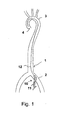
- a schematic human vascular system 1 is shown.
- the femoral arteries 2 which is connected via a main artery to the aortic arch 3 and then opens into the heart chamber 4.
- an introducer sheath 10 is first inserted into the femoral artery 2.
- the femoral artery or any blood vessel is punctured, for example with a steel cannula with a cutting tip.
- a guidewire 12 is pushed through and inserted retrograde over the aortic arch 3 into the left ventricle 4.
- the puncture cannula designed as an introducer sluice first lock 10 which comprises a tubular portion 11 and optionally a dilator not shown here, threaded onto the guide wire and inserted through the dotted spot in the vascular system, the lock a small distance into the lumen the vascular system or even to the site of an element to be inserted is introduced. Subsequently, a fluid pump is introduced through the introducer sheath 10 into the vascular system.
- the tubular portion 11 of the first sheath 10 is inserted into the artery such that the proximal end of the first sheath 10 is outside the femoral artery and thus can be used for introducing, for example, a pump. So it is possible to thread the pump on the guide wire 12 to guide the pump with the help of the guide wire into the left ventricle.
- the method is illustrated merely by inserting a pump into the left ventricle to support cardiac function.
- the pump or another functional element can also be arranged and introduced at other locations in the body's own vascular system.
- Fig. 2 is the area of Fig. 1 represented, in which the first lock 10 is guided by the body's own tissue from the outside into the lumen L G of the femoral artery 2.
- the first lock comprises a tubular section 11, which is connected proximally to a lock housing 13.
- the tubular portion 11 defines a lumen L 1 , which has an inner diameter d 11 .
- the lock housing 13 includes a hemostatic valve known in the art. This prevents that fluid in the lumen L G can escape through the lumen L 1 to the outside.
- the first lock 10 of the Fig. 2 coupled with a second lock 20.
- a tubular portion 21 is shown, which defines a lumen L 2 with an inner diameter d 21 .
- the distal end of the second lock 20 in this case has such an outer diameter that it can be inserted into the lock housing 13.
- the inner diameter d 21 is larger than the inner diameter d 11, however .
- a pump, not shown, located in the lumen L 2 can now be transferred by pressing the second lock lumen L 2 in the first lock lumen L 1 become. Subsequently, the pump is transported through the first lock lumen L 1 to the point in the vascular system at which the pump is to be effective. In this case, the pump can either be guided on a guide wire or be introduced without guidewire through the first lock lumen.
- the first sheath may be advanced distally to the pump site to save the pump and the vessel walls, as well as the shaft catheter, before the pump is pushed out.
- the pump 30 comprises a distal pump unit 31 and a shaft catheter 32 adjoining the proximal end of the distal pump unit 31.
- the shaft catheter 32 has at its proximal end, not shown, a coupling for coupling the shaft catheter 32 to a drive device.
- the drive device can be arranged outside the patient's body and sets a running in the shaft catheter 32 flexible shaft in rotation, which in turn drives the distal pump unit 31.
- the distal pump unit includes a pump housing 33 made of intersecting Nitinol struts.
- the nitinol housing is in part provided with a coating 34 which extends distally and proximally of a rotor 35 arranged in the housing 33.
- the rotor is connected to the shaft 36 passing through the shaft catheter 32 and is thus rotated.
- the housing and the rotor are compressible, ie the pump is a self-decompressible pump.
- the deployment of the pump takes place after pushing out of the distal pump unit from the distal end of a lock.
- the distal pump unit is retracted into the distal end of a lock lumen of a second sheath.
- the lock lumen has an inner diameter which is at least greater than the outer diameter of the shaft catheter.
- the rotor may be displaceable relative to the pump housing in the axial direction, in particular by means of an axial displacement of the drive shaft.
- the rotor can also be fixed in the axial direction with respect to the pump housing.
- the pump has a discharge hose 37, which defines a flow channel for the pumped fluid located proximally of the rotor 35. At the proximal end of the discharge hose 37 are not shown outlet openings.
- the pump can also be switched from a pump mode to a suction mode, so that the pump no longer carries fluid from the distal end to the proximal end, but vice versa.
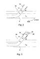
- a pump 30 ' is shown, which is substantially the pump 30 after the Fig. 4 equivalent. For simplicity, details of the pump are not shown. It is only the bulbous housing and the distal of the bulbous housing located "Pigtail" shown, which prevents suction of the heart pump to the heart wall. Proximal to the distal pump unit 31 'runs the wave catheter 32'. Surrounding a region 38 'of the shaft catheter 32' is a second sheath 20 'which comprises a lumen L 2 whose inner diameter d 21 is smaller than the diameter of the distal pump unit 31' in the deployed state.
- the in the Fig. 5 illustrated pump 30 ' is a compressible pump, that is, the distal pump unit 31', which includes, inter alia, the pump housing and the rotor therein, is designed such that it can be compressed, ie reduced in diameter.
- a quality inspector or doctor for example, has been able to convince himself of the correct function of the pump 30 ', e.g.
- pulling the shaft catheter 32' in the proximal direction draws the distal pump unit 31 'into the lumen L 2 of the second sheath 20'.
- the in the Fig. 5 illustrated pump 30 'and the area 38' of the shaft catheter 32 'enclosing second lock 20' form a system 200, which makes it possible to test in good time before surgery, the function of the pump 30 'and then by pulling the distal pump unit 31' in the distal end of the second lock 20 'to compress the pump while avoiding damage to the shaft.
- the system can be realized both with actively decompressible pumps and with self-decompressible pumps, it is particularly suitable for self-decompressible pumps, ie pumps whose distal pump unit outside the lock automatically resumes its original size.
- FIG. 6 an intermediate step is shown in drawing the distal pump unit 30 'into the lumen of the second sheath 20'. It will be appreciated that the distal pump unit 30 'is compressible and can be made smaller in diameter so that the distal pump unit 30' can be received in the lumen of the second sheath 20 '.
- a coupling 39 'adjoining the shaft catheter 32' is provided, which allows a coupling of the shaft extending in the shaft catheter to a drive unit. Since the coupling 39 'often has a larger outer diameter than the inner diameter of the lumen L 2 , the second lock 20' is usually placed in the distal direction before the assembly of the coupling 39 'from the proximal end of the shaft catheter 32', so that the pump System 200, ie the pump with the proximal of the distal pump unit 31 'located second lock 20' and the preassembled coupling 39 ', is delivered. At the Fig. 6 is also a slight expansion of the distal end of the second lock 20 'shown. The trumpet-like expansion 24 'facilitates the insertion of the distal pump unit 31' into the lumen L 2 of the second sheath 20 '.
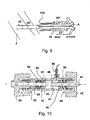
- the distal pump unit 31 ' is located completely in the lumen L 2 of the second sheath 20 ".
- the second sheath 20" has two preassembled handle units 22 ", which better hold or remove the second sheath 20" when the distal pump unit 31 is retracted 'allow in the lumen L 2 or a subsequent tearing.
- a "pigtail” this is likewise drawn into the lumen L 2 , so that the distal pump unit 31 'together with components of the pump located distally of the distal pump unit 31' is located in the lumen L 2 .
- the second sheath 20" is inserted with its distal end into the sheath housing of the first sheath 10.
- the pump is displaced from the second sheath 20 'by pushing the pump in the distal direction, pushing by shunting the shaft catheter 32'.
- the diameter of the distal pump unit 31 ' is further reduced to the inner diameter d 11 of the lumen L 1 .
- the subsequent step is shown, in which the distal pump unit 31 'is located completely in the lumen L 1 of the first lock 10.
- the fact that the distal pump unit 31 'is located completely in the lumen L 1 of the first lock 10 can be determined, for example, by means of a colored marking 50 which is located on the outside of the shaft catheter 32 'is applied, be identified.
- the second sheath 20 " which is formed as a" peel-away "lock, is removed from the shaft catheter 32 'by tearing open the peel-away sheath from the proximal to the distal end and withdrawing it from the shaft catheter 32' directed tearing from the proximal to the distal end may be assisted by notches A, but is primarily due to the alignment of the molecular chains of the plastic used from the proximal to the distal direction.
- the pump 30 is further guided within the lumen L 1 of the first lock 10 to the desired location.
- the first sheath may also be advanced into the immediate vicinity of the site of use before or after insertion of the pump with the distal port mouth.
- the first lock on the necessary length may also be advanced into the immediate vicinity of the site of use before or after insertion of the pump with the distal port mouth.
- a stiffening of the second sheath 20 "is in particular during insertion of the distal pump unit 31 'in the distal end of the second lock lumen L 2 is not necessary, since the risk of kinking of the shaft is greatly reduced in a pulling movement.
- the second lock may comprise a reinforcing structure in the form of an inserted wire, or the tubular portion 21 "of the lock 20" will not be made of a flexible one Plastic, but made of a rigid plastic or metal.
- Another way to stabilize the pump and the second lock is to move the pump 30 'in the distal direction, i. in particular when transferring the pump 30 'from the second lock into the first lock to hold the second lock 20 "by a support device 40 in the form of a stable outer sleeve.
- the pump is first filled with sterile physiological saline and thus completely deaerated.
- the peel-away sluice located proximally of the distal pump unit is advanced to a possibly existing outflow tube.
- the peel-away sluice has a diameter of, for example, 10 Fr.
- the peel-away sluice is surrounded by a sleeve-shaped device for holding the second sluice.
- the distal pump unit optionally with slight rotational movement, retracted into the peel-away lock by a tensile movement is exerted on the shaft catheter in the proximal direction.
- the pump is moved so far into the second lock that a possibly existing pigtail is also recovered in the peel-away lock.
- any dilator present is pulled out of the introducer sheath and removed.
- the pump held in the peel-away lock which for example is initially surrounded by the sleeve for holding the second lock, is pushed into the lock housing until the tip of the peel-away lock abuts against a mechanical stop.
- the pump is transferred from the peel-away lock into the tubular section by pushing the shaft catheter.
- the distal pump unit has been completely transferred into the introducer sheath, as can be checked, for example, by means of an optical marking on the shaft catheter shaft, the peel-away sheath can be torn open and removed from the shaft catheter.
- the pump is advanced within the first sheath into the left ventricle. The first sheath is then withdrawn from the left ventricle to the beginning of the descending aorta.
- the positioning of the distal pump unit in the left ventricle of the heart can be controlled, for example, by fluoroscopy.
- a radiopaque marking on the pump housing or in its vicinity, for example on Catheter, or the pump housing itself is radiopaque.
- the outlet area of the pump, ie the outflow openings of a discharge hose should be in the region of the ascending aorta. This can also be checked with a radiopaque marker. Any existing pigtail catheter tip should abut the tip of the left ventricle of the heart.
- the shaft catheter may have a feed funnel into which the pump can be pulled by train on the drive shaft. Subsequently, the first lock and other remaining components are removed from the vascular system.
- a particular advantage of the invention is the use of a long lock during the implantation and explantation of the pump.
- the long sluice is not only used, as is common in the prior art, for introducing the pump into an endogenous lumen, but for guiding the pump through the sluice lumen in the vicinity of the site of action.
- the lock has a length between 40 and 120 cm. The length is determined by the later place of action of the pump and the physique of the patient.
- the Bleeding of the femoral artery is breastfed with a pressure bandage.
- the pump can be pulled out of the lock lumen of the long lock.
- another guidewire can be placed through the lumen of the sluice, and then, after removal of the sluice, a device for closing the puncture can be guided. This achieves improved hemostasis.
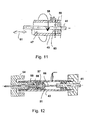
- FIGS. 10 to 13 specifically show an inventive embodiment of the first lock with one or more clamping devices for fixing a tubular portion 41 in a lock housing 43rd
- Fig. 10 shows in a longitudinal section a lock housing 43, which has substantially the shape of a cylindrical sleeve, which is closed at least at the distal, the patient's body-facing end 44 by a pressure screw 45.
- the lock housing 43 has a continuous receiving channel 46 for a tubular portion 41 of the first lock.
- the tubular portion 41 coming from the patient's body into the flushing chamber 47 of the receiving channel 46 continuously, then shown in dashed lines in the proximal direction. This indicates that the tubular portion 41 is axially displaceable with respect to the lock housing 43 within the receiving channel 46 or, in other words, that the lock housing 43 is slidable on the tubular portion 41.
- a functional element such as a pump
- the tubular portion 41 pulled so far in the distal direction of the lock housing 43 or positioned in the production of the first lock so that it ends approximately at the level of the first stop piece 48.
- a second lock with a retracted pump can then be advanced to then move the pump from the second lock to the first lock.
- the first clamping device has as elements the first pressure screw 45, a first clamping ring 50 made of an elastomeric material and the first stop piece 48.
- the pressure screw is screwed by means of an external thread in the region of the overlap with the distal end 44 of the lock housing 43 with this.
- a manual rotation of the pressure screw 45 thus causes a movement of the pressure screw in the axial direction, which leads to an axial compression or expansion of the clamping ring 50.
- the clamping ring 50 tends to dodge radially inwardly and outwardly to maintain its volume and thus clamps the tubular portion 41 because it experiences resistance on its proximal side by the first stopper 48.
- the tubular portion 41 is fixed axially against the lock housing 43.
- This fixation can be solved simply by loosening the pressure screw 45, so that the tubular portion 41 can then easily be moved axially in the lock housing 43.
- the clamping ring can do so in the relaxed state an inner diameter have the same as or greater than the diameter of the first lock.
- the tubular portion 41 as far as possible pushed into the patient's body to allow insertion of the pump in the protection of the lock to the place of use, for example in a Herzventrikel, so after deployment of the pump, the tubular portion 41 is pulled out, and the lock as a whole protrudes relatively far from the patient's body. Thereafter, the clamping device 48, 45, 50 dissolved and the lock housing 43 are pushed on the tubular portion 41 closer to the patient's body. In this case, the tubular portion 41 then passes through the lock housing 43 completely and possibly projects out of it in the proximal direction. Thereupon, by means to be described in more detail below, the tubular portion 41 may be partially severed to remove the excess length.
- a so-called combined hemostasis valve consisting of a dome valve 51 and a valve plate 52, is provided for better sealing.
- the valve plate closes the lock housing 43, if at this point neither the tubular portion 41 nor a wave catheter penetrates the receiving channel 46, while the dome valve 51 is optimized around a string-shaped body, for example the tubular portion or a catheter.
- a further pressure screw 54 is provided, which in Principle works as well as the first pressure screw 45 and the compression of a second clamping ring 56 causes over a second pressure ring 55 against a second mechanical stop 57.
- the second clamping ring 56 tapers at its distal end, which favors a deformation radially inwardly when exerting an axial pressure by the pressure screw 54.
- the second stop 57 is conical. However, it can also be used at this point a non-conical, but in cross-section rectangular or round clamping ring 56.
- a flushing device 58 indicated schematically, which allows the flushing of the washing chamber 47 with a liquid which prevents the penetration of germs through the first lock in the patient's body. This flushing is particularly effective when the tubular portion 41 terminates in the flushing space 47 or on the distal side thereof, so that both the outside and the inside of the tubular portion 41 are reached by the flushing liquid.
- Fig. 11 shows an example of the arrangement and operation of a cutting device according to the invention.
- predetermined breaking points are provided, these can be appropriately introduced when using the first lock by a cutting device.
- a cutting device with blades 59, 60 are provided, which intersect in the circumferential direction, for example, upon rotation of the lock housing relative to the tubular portion. It can also be introduced cuts in the axial direction.
- the blades 59, 60 may also be arranged so that they intersect in the axial direction, as indicated by the arrow 61, during a movement of the tubular portion 41 in the longitudinal direction. It is also possible to provide both blades for cutting in the circumferential direction and a blade for cutting in the longitudinal direction.
- the blades 59, 60 can be moved in the direction radially to the tubular portion 41 by an operation from the outside of the lock housing 43.
- a pressure on the blades can then be exerted by hand and the unneeded part of the tubular portion 41 can be cut off.
- An abutment prevents the depth of cut from exceeding a critical level, thereby damaging any catheter within the sheath.
- the illustrated blades may also form a cutting device for a second lock.
- the Fig. 12 shows an advantageous use of the second clamping device on the proximal side of the lock housing 43 after the tubular portion 41 is shortened and a shaft catheter 61 from the proximal end of the tubular portion 41 out and on to a not shown coupling device for a drivable shaft of a pump from the Lock housing 43 leads.
- the shaft catheter is sealed in the above-mentioned mandrel seal 51, and the clamping device with the elements of the second pressure screw 54 and the second clamping ring 56, which is axially compressed by the pressure piece 55 relative to a second stop 57, so far deviates radially inwardly he the shaft catheter 61, which has a substantially smaller outer diameter than the tubular portion 41 or a second lock, clamps and in particular also additionally seals. In this way, both the tubular portion 41 and the shaft catheter 61 protruding therefrom can be fixed in the lock housing 43.
- the second clamping device is also suitable, when inserting a second lock into the lock housing 43, to fix the second lock with the second clamping ring 56 so that it is sufficiently fixed relative to the lock housing 43 and in particular also to the tubular section 41 for pushing through the shaft catheter 61 is.
- the first and second clamping ring 50, 56 may consist of an elastomer, for example a rubber or a silicone elastomer, and thus fully elastic, but be volumeninkompressibel deformable. However, it is at this point also the use of an elastic foam conceivable, which is partially volumenkompressibel.
- FIG. 13 schematically another type of clamping ring 62 is shown, which may for example consist of a plastic or a metal and in particular slotted and thus radially compressible.
- the slotted clamping ring 62 has a conical outer contour against which the conical contour of a pressure piece 63 presses to radially compress the clamping ring as soon as an axial compressive force in the direction of the arrow 65, for example by a pressure screw shown above, is exerted on the pressure piece 63 ,
- the slotted clamping ring 62 is fixed axially by the stopper 64.
- the Fig. 14 shows a lock housing 43 ', which has in its interior a receiving channel 46 for a lock or a catheter.
- the lock housing 43 ' has at its distal end 44 on this attached tubular portion 41, which can be glued, for example, in an opening of the lock housing, cast or otherwise secured there.
- the tubular portion 41 is inserted into the opening of the lock housing 43 'up to a mechanical stop 63.
- the system can also be designed so that the second lock 20 '''directly to the tubular Section 41 ends.
- the second lock 20 ''' is, not shown, for example, retracted a functional element in the form of a pump with a hollow catheter.
- the two locks within the receiving channel 46 are aligned coaxially with each other, and the second lock 20 '' 'by means of a Clamping device fixed.
- the clamping device has an elastic clamping ring 56 ', which is tapered at its distal end and is pressed against a mechanical stop 57'.
- a pressure screw 54 ' which has an external thread 64, axial pressure on the clamping ring 56' is exercised.
- the pressure screw 54 ' is screwed for this purpose in the opening of the tubular part of the lock housing 43', so that it moves axially in the direction of the arrow 65.
- the clamping ring 56 ' consists for example of an elastomer, expands at an axial pressure in the radial direction and thus clamps a strand-shaped body, which is located in the receiving channel 46.
- the second lock 20 ''' has a wall thickness between 0.3 and 0.7 mm and is made of a sufficiently stable material, so that at radial pressure, the second lock can be clamped without at the same time clamped therein the catheter running in it becomes. The catheter can thus be easily shifted from the proximal end of the second lock 20 '''in the tubular portion 41.
- the second lock 20 "' is through a combined plate and dome seal 51, 52 sealed in a wash chamber 47.
- the second lock on the handles 67, 68 can be torn open and removed.
- the second lock has a pre-weakening or incision along its axial direction or a corresponding predetermined molecular structure, which allows a longitudinal tearing to the distal end of the second sheath and a corresponding removal of the second sheath. For tearing it may be useful to solve the clamping device 54 ', 56', 57 '.
- the clamping device 54 ', 56', 57 ' can be clamped so far that the smaller diameter catheter is clamped in the receiving space 46 by the further radial compression of the clamping ring 56'.
- the clamping device can be released and the catheter readjusted and fixed again.
- two cylindrical elements are sealingly inserted into one another in the construction described, it is advantageous to use a cone seal with a cone angle of a few degrees, as is generally known in the medical field.
- the described embodiment of a lock allows, for example, an implantable heart pump from a second lock, in which it can be kept in stock after a first inspection, in a first lock, which leads into a patient's body, without problems and with little effort and high reliability convict.
Abstract
Description
Die Erfindung liegt auf dem Gebiet der Mechanik und speziell der Medizintechnik und bezieht sich auf eine Schleuseneinrichtung zum Einführen eines Katheters in den Körper eines Patienten.The invention is in the field of mechanics and especially medical technology and relates to a lock device for introducing a catheter into the body of a patient.
Insbesondere in der mikroinvasiven oder minimalinvasiven Anwendung im Bereich der Medizin werden häufig Funktionselemente wie beispielsweise Stents, Fräsköpfe zum Ausfräsen von Blutgefäßen sowie Herzunterstützungspumpen mittels Kathetern durch eine Öffnung in das Körperinnere eines Patienten, speziell in körpereigene Gefäße, insbesondere Blutgefäße, eingeführt. Um solche Katheter mit minimierter Traumatisierung des betroffenen Gewebes und auch unter Minimierung des Beschädigungsrisikos für die empfindlichen medizinischen Geräte ein- oder mehrmals einführen zu können, werden häufig Schleusen verwendet, die dauerhaft oder vorübergehend in den Körper eines Patienten eingebracht werden und die ein inneres Lumen aufweisen, das das Durchführen eines Katheters oder anderer Funktionselemente erlaubt. Zum Einführen einer solchen Schleuse in den Patientenkörper ist die sogenannte Seldinger-Technik bekannt, die weiter unten im Zusammenhang mit der
Ein entsprechendes Verfahren ist beispielsweise aus der
Ist eine derartige Schleuse einmal installiert, so kann sie dauerhaft oder wiederholt zum Einführen und Entnehmen eines Katheters verwendet werden.Once such a lock has been installed, it can be used permanently or repeatedly to insert and remove a catheter.
Eine spezielle Anwendung liegt in der Verwendung einer derartigen Schleuse für komprimierbare Blutpumpen oder andere Funktionselemente, die zunächst zur besseren Einbringbarkeit in den Körper komprimiert, insbesondere radial komprimiert werden, im komprimierten Zustand durch die Schleuse an den Ort des Einsatzes oder bis in die Nähe des Einsatzortes eingeführt und danach dort expandiert werden. Zu diesem Zweck sind entsprechende Blutpumpen bekannt, die einen Pumpenkopf am distalen Ende eines Hohlkatheters aufweisen, wobei der Pumpenkopf einen Rotor mit radial expandierbaren Förderschaufeln sowie ein ebenfalls komprimier- und expandierbares Gehäuse aufweist. Die entsprechenden Elemente sind so ausgebildet, dass sie beispielsweise selbsttätig expandieren, wenn sie beispielsweise vorher elastisch komprimiert sind, oder dass sie zu Beginn eines Rotationsbetriebs durch den Widerstand der zu fördernden Flüssigkeit, beispielsweise des Blutes, expandiert werden (gilt insbesondere für Förderschaufeln des Rotors).A special application is the use of such a lock for compressible blood pumps or other functional elements that are initially compressed for better introduction into the body, in particular radially compressed, in the compressed state through the lock to the place of use or to the vicinity of the site introduced and then expanded there. For this purpose, corresponding blood pumps are known, which have a pump head at the distal end of a hollow catheter, wherein the pump head has a rotor with radially expandable conveying blades and also a compressible and expandable housing. The corresponding elements are designed so that they expand, for example, automatically, for example, if they are previously elastically compressed, or that they are at the beginning of a rotation operation by the resistance of the liquid to be conveyed, such as the blood, expanded (applies in particular for conveying blades of the rotor) ,
Auch andere Effekte wie beispielsweise Formgedächtniseffekte bei sogenannten Formgedächtnislegierungen, beispielsweise Nitinol, können für den Zweck einer nachträglichen Formänderung ausgenutzt werden.Other effects such as shape memory effects in so-called shape memory alloys, such as nitinol, can be exploited for the purpose of a subsequent change in shape.
Entsprechende komprimierbare Blutpumpen sind beispielsweise aus der
Solche Blutpumpen oder auch andere Funktionselemente können zur besseren Einbringbarkeit mittels einer oben beschriebenen Schleuse vorteilhaft vorkomprimiert werden und beispielsweise in einer zweiten Schleuse für die Behandlung eines Patienten vor dem Einführen in die erste Schleuse bereitgehalten werden. Die zweite Schleuse ist dann derart konzipiert, dass das Funktionselement, insbesondere der Pumpenkopf, in ihrem Innenraum (Lumen) komprimiert gehalten ist, beispielsweise in demselben Durchmesser, der auch für das Einführen in die erste Schleuse benötigt wird, oder geringfügig größer. Zum Überführen der Pumpe von der zweiten Schleuse in die erste Schleuse werden dann typischerweise die beiden Schleusen derart gekoppelt, dass sie koaxial zueinander mit möglichst geringem Abstand voneinander gekoppelt werden, um die Pumpe aus der zweiten Schleuse heraus und in die erste Schleuse hinein axial zu verschieben.Such blood pumps or other functional elements can be advantageously pre-compressed for better applicability by means of a lock described above and kept ready for example in a second lock for the treatment of a patient before insertion into the first lock. The second lock is then designed such that the functional element, in particular the pump head, is kept compressed in its interior space (lumen), for example in the same diameter that is also required for insertion into the first lock, or slightly larger. For transferring the pump from the second lock into the first lock, the two locks are then typically coupled in such a way that they are coupled coaxially to one another with the shortest possible distance in order to axially displace the pump out of the second lock and into the first lock ,
Dieser Vorgang ist kritisch, da alle Bauteile, insbesondere der Katheter, der Pumpenkopf und die zweite Schleuse mechanisch besonders beansprucht werden. Zudem besteht ein Problem darin, dass dieser Schleusenvorgang unter Operationsbedingungen üblicherweise von Hand mit geringen weiteren Hilfsmitteln durchgeführt werden muss, wobei hohe Anforderungen an die Einfachheit des Vorgangs und an die Zuverlässigkeit gestellt werden.This process is critical because all components, in particular the catheter, the pump head and the second lock are subjected to mechanical stress. In addition, there is a problem that this lock operation under operating conditions usually be carried out by hand with little further aids, with high demands on the simplicity of the operation and on the reliability.
Der vorliegenden Erfindung liegt vor diesem Hintergrund die Aufgabe zugrunde, eine Schleuseneinrichtung der eingangs genannten Art zu schaffen, die mit hoher Zuverlässigkeit, geringer Anfälligkeit, geringem konstruktivem Aufwand und einem geringen Schädigungsrisiko für Patienten und die medizinischen Geräte das Einführen eines Funktionselementes in den Patientenkörper ermöglicht.The present invention is based on this background the object to provide a lock device of the type mentioned, which allows high reliability, low susceptibility, low design effort and a low risk of damage to patients and the medical devices, the insertion of a functional element in the patient's body.
Die Aufgabe wird mit den Merkmalen der Erfindung gemäß den Patentansprüchen 1 und 10 und gemäß einem Verfahren nach Patentanspruch 12 gelöst.The object is achieved with the features of the invention according to
Gemäß der Erfindung wird eine Schleuseneinrichtung zum Einführen eines Katheters in einen Patientenkörper mit einer ersten Schleuse geschaffen, deren proximales Ende beim bestimmungsgemäßen Gebrauch zur Anordnung außerhalb des Patientenkörpers vorgesehen ist, während das distale Ende der ersten Schleuse im Gebrauch innerhalb des Patientenkörpers liegt. Die erste Schleuse weist einen schlauchförmigen Abschnitt und an dessen proximalem Ende ein Schleusengehäuse mit einem Aufnahmekanal für einen strangförmigen Körper, insbesondere einen Katheter und/oder eine zweite Schleuse, auf.According to the invention, there is provided a lock device for inserting a catheter into a patient's body having a first sheath, the proximal end of which is intended for use outside the patient's body when used as intended, while the distal end of the first sheath is within the patient's body during use. The first lock has a tubular portion and at its proximal end a lock housing with a receiving channel for a strand-shaped body, in particular a catheter and / or a second lock on.
Durch Vorsehen einer Klemmvorrichtung an dem Aufnahmekanal kann der strangförmige Körper, insbesondere Katheter und/oder eine Schleuse, in dem Aufnahmekanal eingeklemmt werden. Hierdurch kann, wenn ein Funktionselement, insbesondere eine Pumpe, am Ende eines Katheters in einer zweiten Schleuse vorkomprimiert ist, diese zweite Schleuse in das Schleusengehäuse eingeführt und dort mittels der Klemmvorrichtung fixiert werden. Damit können gleichzeitig die zweite Schleuse und die erste Schleuse koaxial zueinander ausgerichtet und in einem gewünschten relativen Abstand axial zueinander fixiert werden, so dass der Katheter mit dem Funktionselement von der zweiten Schleuse in die erste Schleuse hinübergeschoben werden kann.By providing a clamping device on the receiving channel, the strand-shaped body, in particular catheter and / or a lock, can be clamped in the receiving channel. In this way, if a functional element, in particular a pump, at the end of a Catheter is precompressed in a second lock, this second lock introduced into the lock housing and fixed there by means of the clamping device. Thus, at the same time, the second lock and the first lock can be aligned coaxially with one another and fixed axially relative to one another at a desired relative distance, so that the catheter with the functional element can be pushed over from the second lock into the first lock.
Die Wandstärke und das Material der zweiten Schleuse werden so ausgewählt, dass die zweite Schleuse in der Klemmvorrichtung eingeklemmt werden kann, ohne dass gleichzeitig der Katheter in der zweiten Schleuse mit eingeklemmt wird. Die zweite Schleuse wird derart stabil ausgeführt, dass sie beim Klemmen nur unwesentlich komprimiert wird. Die Wanddicke der hohlzylindrischen zweiten Schleuse kann vorteilhaft zwischen 0,2 und 1,0 mm, insbesondere zwischen 0,3 und 0,7 mm betragen.The wall thickness and the material of the second lock are selected so that the second lock can be clamped in the clamping device, without at the same time the catheter is clamped in the second lock with. The second lock is made so stable that it is compressed only insignificantly during clamping. The wall thickness of the hollow-cylindrical second lock can advantageously be between 0.2 and 1.0 mm, in particular between 0.3 and 0.7 mm.
Gleichzeitig wird die Möglichkeit geschaffen, nach dem Einführen des Katheters und/oder des Funktionselements in die erste Schleuse die zweite Schleuse nach dem Lösen der Klemmvorrichtung zu entfernen und diese beispielsweise als Peel-away-Schleuse auszugestalten, so dass sie durch Aufreißen entfernt werden kann, wobei der Katheter in dem Aufnahmekanal bleibt. Der Katheter kann dann trotz seines geringeren Durchmessers in der Klemmvorrichtung geklemmt werden, um das Funktionselement im Patientenkörper relativ zu der ersten Schleuse zu fixieren. Nach einer gewissen Zeit nach dem Einführen, wenn die mechanischen Teile sich gesetzt und die Körpertemperatur des Patienten angenommen haben, kann eine Nachjustierung erforderlich sein, so dass dann die Klemmvorrichtung erneut gelöst, der Katheter neu justiert und die Klemmvorrichtung wieder fixiert werden kann. Alternativ kann auch vorgesehen werden, den Katheter in einer weiteren auf den geringeren Durchmesser abgestimmten Klemmvorrichtung zu fixieren.At the same time the possibility is created to remove after insertion of the catheter and / or the functional element in the first lock the second lock after loosening the clamping device and this example, as a peel-away lock to design so that it can be removed by tearing, the catheter remains in the receiving channel. The catheter can then be clamped despite its smaller diameter in the clamping device to fix the functional element in the patient's body relative to the first lock. After a period of time after insertion, when the mechanical parts have settled and the body temperature of the patient has assumed, a readjustment may be required be so that then released the clamping device again, the catheter readjusted and the clamping device can be fixed again. Alternatively, it can also be provided to fix the catheter in a further clamping device adapted to the smaller diameter.
Eine vorteilhafte Ausgestaltung der Erfindung sieht vor, dass die Klemmvorrichtung einen elastisch radial deformierbaren Klemmring aufweist. Ein solcher radial deformierbarer Klemmring stellt eine konstruktiv sehr einfache und kostengünstige Art dar, eine Klemmvorrichtung zu schaffen, die ohne die Gefahr einer Verletzung einer zweiten Schleuse oder eines Katheters eine zuverlässige Klemmung gestattet. Der Klemmring kann vorteilhaft aus einem Elastomer bestehen und volumeninkompressibel sein, so dass er bei axialer Kompression radial ausgedehnt wird. Er kann jedoch auch aus einem Schaumstoff bestehen, der teilweise volumenkompressibel ist, sich jedoch ebenso bei einer Axialkompression radial ausdehnt.An advantageous embodiment of the invention provides that the clamping device has an elastically radially deformable clamping ring. Such a radially deformable clamping ring is a structurally very simple and inexpensive way to provide a clamping device that allows reliable clamping without the risk of injury to a second lock or a catheter. The clamping ring may advantageously consist of an elastomer and be volume incompressible, so that it is radially expanded in axial compression. However, it can also consist of a foam, which is partially volume compressible, but also expands radially in an axial compression.
Zudem kann vorgesehen sein, dass der Klemmring aus einem Kunststoff oder Metall besteht und geschlitzt ist. Ein derartiger Klemmring kann beispielsweise auch außen eine konische Form aufweisen, um mittels eines weiteren als Klemmkonus ausgebildeten Rings durch dessen axiale Bewegung radial komprimiert werden zu können.In addition, it can be provided that the clamping ring consists of a plastic or metal and is slotted. Such a clamping ring may, for example, on the outside have a conical shape in order to be radially compressed by means of a further ring formed as a clamping cone by the axial movement can.
Vorteilhaft kann die Erfindung dadurch ausgestaltet werden, dass der Klemmring mittels einer axial in Bezug auf den Aufnahmekanal wirkenden Schraubvorrichtung in Richtung radial nach innen expandierbar ist. Mittels einer solchen Schraubvorrichtung, beispielsweise mittels eines Schraubrades, dessen Durchmesser auch größer als der des Schleusengehäuses sein kann, kann auch unter Operationsbedingungen in einfacher Weise eine Kompression eines Klemmrings und damit ein Verklemmen der zweiten Schleuse oder des Katheters vorgenommen werden.Advantageously, the invention can be configured in that the clamping ring is radially inwardly expandable by means of an axially acting with respect to the receiving channel screwing. By means of such a screwing device, for example by means of a Schraubrades whose diameter can also be greater than that of the lock housing, a compression of a clamping ring and thus jamming of the second lock or the catheter can be made under operating conditions in a simple manner.
Bei Verwendung eines im Querschnitt keilförmigen zylindrischen Druckstücks kann die Erfindung dadurch realisiert werden, dass der Klemmring mittels der axial wirkenden Schraubvorrichtung und eines axial bewegbaren Keilkörpers, insbesondere eines im Querschnitt keilförmigen Rings, radial nach innen komprimiert wird.When using a wedge-shaped in cross-section cylindrical pressure piece, the invention can be realized in that the clamping ring by means of the axially acting screw and an axially movable wedge body, in particular a wedge-shaped in cross-section ring, is compressed radially inwardly.
Um das Eindringen von Keimen durch die erste Schleuse in den Patientenkörper sowohl bei Einführung einer zweiten Schleuse und eines Katheters als auch später im Betrieb zu minimieren, kann weiter vorgesehen sein, dass auf der in axialer Richtung gesehen dem Druckstück oder dem Keilkörper gegenüberliegenden Seite des Klemmrings eine radiale Erweiterung des Aufnahmekanals angeordnet ist, die eine Spülvorrichtung aufweist.In order to minimize the penetration of germs through the first sheath into the patient's body both when introducing a second sheath and a catheter and later during operation, it can further be provided that on the side of the clamping ring opposite the pressure piece or the wedge body in the axial direction a radial extension of the receiving channel is arranged, which has a flushing device.
Zu demselben Zweck und weiterhin, um das Austreten von Körperflüssigkeiten, insbesondere Blut, durch die Schleuse zu verhindern, kann gemäß der Erfindung auch vorgesehen sein, dass in dem Spülraum, insbesondere auf der in axialer Richtung gesehen dem Druckstück oder dem Keilkörper gegenüberliegenden Seite des Klemmrings ein den Aufnahmekanal abdichtendes Ventil angeordnet ist. Ein solches Ventil kann beispielsweise als Doppelventil mit einem Plattenventil und einem Domventil ausgestaltet sein, wobei das Plattenventil dann optimal dichtet, wenn der Aufnahmekanal nicht von einem Katheter und/oder einer zweiten Schleuse durchsetzt ist, so dass das Plattenventil insgesamt geschlossen gehalten werden kann. Wird ein Katheter oder ein anderer strangförmiger Körper durchgeschoben, so erlaubt das Domventil, das beispielsweise die geometrische Form einer Kalotte annehmen kann, eine optimale Dichtung um den strangförmigen Körper herum. Es sind aber auch andere Ausführungen des Ventils möglich um die genannten Abdichtungsfunktionen zu erfüllen.For the same purpose and furthermore in order to prevent leakage of body fluids, in particular blood, through the sluice, according to the invention it can also be provided that in the scavenging space, in particular on the side of the clamping ring opposite the thrust piece or the wedge body, viewed in the axial direction a valve sealing the receiving channel is arranged. Such a valve may for example be designed as a double valve with a plate valve and a dome valve, the plate valve then seals optimally when the receiving channel is not from a catheter and / or a second Lock is interspersed, so that the plate valve can be kept closed as a whole. If a catheter or other strand-shaped body pushed through, so allows the dome valve, which can for example take the geometric shape of a dome, an optimal seal around the strand-like body around. But there are also other versions of the valve possible to meet the said sealing functions.
Die Erfindung bezieht sich außer auf eine Schleuseneinrichtung der oben genannten Art auch auf eine Kathetereinrichtung mit einer entsprechenden Schleuseneinrichtung und mit einem Katheter, der den Aufnahmekanal durchsetzt und in der Klemmvorrichtung fixiert ist.The invention relates except to a lock device of the type mentioned above also to a catheter device with a corresponding lock device and with a catheter which passes through the receiving channel and is fixed in the clamping device.
Weiter soll auch eine Kathetereinrichtung mit einer Schleuseneinrichtung, wie sie oben beschrieben wurde, und einem Katheter sowie einer den Katheter umgebenden zweiten hülsenförmigen Schleuse, die den Aufnahmekanal durchsetzt, Gegenstand der Erfindung sein, wobei die hülsenförmige zweite Schleuse in der Klemmvorrichtung fixiert ist.Further, a catheter device with a lock device, as described above, and a catheter and a second sleeve-shaped lock surrounding the catheter, which passes through the receiving channel, the object of the invention, the sleeve-shaped second lock is fixed in the clamping device.
Die Erfindung bezieht sich außer auf eine Schleuseneinrichtung und eine Kathetereinrichtung der oben beschriebenen Art auch auf ein Verfahren zum Einführen eines Katheters in einen Patientenkörper mittels einer Schleuseneinrichtung gemäß einer der oben beschriebenen Varianten sowie mit einer zweiten Schleuse, wobei zunächst die zweite Schleuse gemeinsam mit dem Katheter in die erste Schleuse, insbesondere bis zu einem mechanischen Anschlag, eingeführt wird und wobei darauf die zweite Schleuse mittels der Klemmvorrichtung fixiert wird und danach der Katheter von der zweiten Schleuse in die erste Schleuse überführt wird.The invention relates, in addition to a lock device and a catheter device of the type described above, to a method for inserting a catheter into a patient's body by means of a lock device according to one of the variants described above and with a second lock, wherein first the second lock together with the catheter is introduced into the first lock, in particular up to a mechanical stop, and wherein thereon the second lock is fixed by means of the clamping device and thereafter the catheter is transferred from the second lock to the first lock.
Eine vorteilhafte Ausgestaltung des erfindungsgemäßen Verfahrens sieht vor, dass nach dem Einführen des Katheters in die erste Schleuse die zweite Schleuse, insbesondere durch Auf- oder Abreißen, entfernt wird.An advantageous embodiment of the method according to the invention provides that after insertion of the catheter into the first lock, the second lock, in particular by tearing up or tearing off, is removed.
Weiter kann das erfindungsgemäße Verfahren vorteilhaft vorsehen, dass nach dem Entfernen der zweiten Schleuse der Katheter in der Klemmvorrichtung unmittelbar fixiert wird.Furthermore, the method according to the invention can advantageously provide for the catheter to be fixed directly in the clamping device after removal of the second sheath.
Die Erfindung wird nachfolgend anhand eines Ausführungsbeispiels in einer Zeichnung gezeigt und anschließend beschrieben. Dabei zeigt
- Fig. 1
- eine schematische Übersicht über ein Gefäßsystem mit einer eingeführten ersten Schleuse;
- Fig. 2
- eine Detailansicht eines Ausschnitts der
Fig. 1 ; - Fig. 3
- eine Ausführungsform der Erfindung mit einer ersten Schleuse und einer zweiten Schleuse;
- Fig. 4
- eine Ausführungsform einer Pumpe;
- Fig. 5
- eine zweite Schleuse mit einer aus dieser extrahierten Pumpe;
- Fign. 6,
- 7 das Einziehen einer Pumpe in eine zweite Schleuse;
- Fign. 8, 9
- das Überführen einer Pumpe von einer zweiten in eine erste Schleuse;
- Fig. 10
- einen Längsschnitt durch ein Schleusengehäuse mit einem schlauchförmigen Abschnitt;
- Fig. 11
- einen Längsschnitt durch einen Teil eines Schleusengehäuses mit einer Schneidvorrichtung;
- Fig. 12
- einen Längsschnitt durch ein Schleusengehäuse mit einer Klemmvorrichtung für den schlauchförmigen Abschnitt und einer weiteren Klemmvorrichtung;
- Fig. 13
- einen Längsschnitt durch einen alternativen Klemmring mit einem konischen Druckstück; und
- Fig. 14
- einen Längsschnitt durch ein Schleusengehäuse mit einer Klemmvorrichtung für einen proximal eingeschobenen strangförmigen Körper.
- Fig. 1
- a schematic overview of a vascular system with an inserted first lock;
- Fig. 2
- a detailed view of a section of the
Fig. 1 ; - Fig. 3
- an embodiment of the invention with a first lock and a second lock;
- Fig. 4
- an embodiment of a pump;
- Fig. 5
- a second lock with a pump extracted therefrom;
- FIGS. 6
- 7 the drawing of a pump in a second lock;
- FIGS. 8, 9
- the transfer of a pump from a second to a first lock;
- Fig. 10
- a longitudinal section through a lock housing with a tubular portion;
- Fig. 11
- a longitudinal section through a part of a lock housing with a cutting device;
- Fig. 12
- a longitudinal section through a lock housing with a clamping device for the tubular portion and another clamping device;
- Fig. 13
- a longitudinal section through an alternative clamping ring with a conical pressure piece; and
- Fig. 14
- a longitudinal section through a lock housing with a clamping device for a proximally inserted strand-like body.
In der
Der schlauchförmige Abschnitt 11 der ersten Schleuse 10 ist derart in die Arterie eingeführt, dass das proximale Ende der ersten Schleuse 10 außerhalb der femoralen Arterie liegt und somit zum Einführen beispielsweise einer Pumpe genutzt werden kann. So ist es möglich, die Pumpe auf dem Führungsdraht 12 aufzufädeln, um die Pumpe mithilfe des Führungsdrahtes bis in den linken Herzventrikel zu führen.The
Es ist auch möglich, den schlauchförmigen Abschnitt 11 der ersten Schleuse 10 durch den Führungsdraht geführt bis in den linken Herzventrikel zu führen und den Führungsdraht 12 anschließend aus der ersten Schleuse zu entfernen. Eine etwaige Pumpeneinheit wird anschließend durch das erste Schleusenlumen bis in die Nähe oder bis in den linken Ventrikel 4 geführt.It is also possible to guide the
Vorliegend wird das Verfahren lediglich anhand des Einführens einer Pumpe in den linken Herzventrikel zum Unterstützen einer Herzfunktion dargestellt. Für den Fachmann ist jedoch leicht erkennbar, dass die Pumpe oder ein anderes Funktionselement auch an andere Stellen im körpereigenen Gefäßsystem angeordnet und eingebracht werden kann.In the present case, the method is illustrated merely by inserting a pump into the left ventricle to support cardiac function. For However, the person skilled in the art will readily recognize that the pump or another functional element can also be arranged and introduced at other locations in the body's own vascular system.
In der
Das Schleusengehäuse 13 enthält ein im Stand der Technik bekanntes hämostatisches Ventil. Dieses verhindert, dass im Lumen LG befindliches Fluid durch das Lumen L1 nach außen austreten kann.The
In der Darstellung der
Eine nicht dargestellte, im Lumen L2 befindliche Pumpe kann nun durch Drücken vom zweiten Schleusenlumen L2 in das erste Schleusenlumen L1 überführt werden. Anschließend wird die Pumpe durch das erste Schleusenlumen L1 bis an die Stelle im Gefäßsystem transportiert, an welcher die Pumpe ihre Wirkung entfalten soll. Hierbei kann die Pumpe entweder auf einem Führungsdraht geführt werden oder ohne Führungsdraht durch das erste Schleusenlumen eingebracht werden. Die erste Schleuse kann, um die Pumpe und die Gefäßwände sowie den Wellenkatheter zu schonen, distal bis zum Einsatzort der Pumpe vorgeschoben werden, bevor die Pumpe herausgeschoben wird.A pump, not shown, located in the lumen L 2 can now be transferred by pressing the second lock lumen L 2 in the first lock lumen L 1 become. Subsequently, the pump is transported through the first lock lumen L 1 to the point in the vascular system at which the pump is to be effective. In this case, the pump can either be guided on a guide wire or be introduced without guidewire through the first lock lumen. The first sheath may be advanced distally to the pump site to save the pump and the vessel walls, as well as the shaft catheter, before the pump is pushed out.
Anhand der
Die distale Pumpeneinheit umfasst ein Pumpengehäuse 33, welches aus sich kreuzenden Nitinolstreben hergestellt ist. Das Nitinolgehäuse ist zu Teilen mit einer Beschichtung 34 versehen, welche sich distal und proximal eines im Gehäuse 33 angeordneten Rotors 35 erstreckt. Der Rotor ist mit der durch den Wellenkatheter 32 verlaufenden Welle 36 verbunden und wird so in Drehung versetzt. Das Gehäuse und der Rotor sind komprimierbar, d. h., die Pumpe ist eine selbstentkomprimierbare Pumpe. Die Entfaltung der Pumpe vollzieht sich nach dem Herausschieben der distalen Pumpeneinheit aus dem distalen Ende einer Schleuse. Zum Komprimieren der Pumpe in Vorbereitung der Implantation wird die distale Pumpeneinheit in das distale Ende eines Schleusenlumens einer zweiten Schleuse eingezogen. Das Schleusenlumen besitzt dabei einen Innendurchmesser, welcher zumindest größer als der Außendurchmesser des Wellenkatheters ist.The distal pump unit includes a
Der Rotor kann gegenüber dem Pumpengehäuse in Axialrichtung verschiebbar sein, insbesondere mittels einer Axialverschiebung der Antriebswelle. Der Rotor kann andererseits auch in Axialrichtung gegenüber dem Pumpengehäuse fixiert sein.The rotor may be displaceable relative to the pump housing in the axial direction, in particular by means of an axial displacement of the drive shaft. On the other hand, the rotor can also be fixed in the axial direction with respect to the pump housing.
Optional weist die Pumpe einen Abströmschlauch 37 auf, welcher einen proximal des Rotors 35 gelegenen Strömungskanal für das gepumpte Fluid definiert. Am proximalen Ende des Abströmschlauchs 37 befinden sich nicht näher dargestellte Auslassöffnungen.Optionally, the pump has a
Selbstverständlich kann die Pumpe auch von einem Pumpbetrieb in einen Saugbetrieb umgeschaltet werden, so dass die Pumpe nicht länger Fluid vom distalen Ende ans proximale Ende führt, sondern umgekehrt.Of course, the pump can also be switched from a pump mode to a suction mode, so that the pump no longer carries fluid from the distal end to the proximal end, but vice versa.
Eine detailliertere Beschreibung einer weiteren geeigneten Pumpe kann beispielsweise der Druckschrift
Anhand der
In der
Die in der
In der
Ferner ist in der
In der
In der
In der
Anschließend wird die zweite Schleuse 20", welche als eine "Peel-away"-Schleuse ausgebildet ist, vom Wellenkatheter 32' entfernt, indem die Peel-away-Schleuse vom proximalen zum distalen Ende hin aufgerissen und vom Wellenkatheter 32' abgezogen wird. Das gerichtete Aufreißen vom proximalen zum distalen Ende hin kann durch Einkerbungen A unterstützt werden, beruht jedoch vorwiegend auf der Ausrichtung der Molekülketten des verwendeten Kunststoffs von der proximalen in die distale Richtung.Subsequently, the
Nachdem die Peel-away-Schleuse entfernt wurde, wird die Pumpe 30' weiter innerhalb des Lumens L1 der ersten Schleuse 10 bis zum gewünschten Ort geführt.After the peel-away lock has been removed, the pump 30 'is further guided within the lumen L 1 of the
Wahlweise kann die erste Schleuse auch vor oder nach dem Einführen der Pumpe mit der distalen Schleusenmündung in die unmittelbare Nähe des Einsatzortes vorgeschoben werden. Hierzu weist die erste Schleuse die notwendige Länge auf.Optionally, the first sheath may also be advanced into the immediate vicinity of the site of use before or after insertion of the pump with the distal port mouth. For this purpose, the first lock on the necessary length.
Eine Versteifung der zweiten Schleuse 20" ist insbesondere beim Einziehen der distalen Pumpeneinheit 31' in das distale Ende des zweiten Schleusenlumens L2 nicht notwendig, da die Gefahr eines Abknickens der Welle bei einer Ziehbewegung stark reduziert ist.A stiffening of the
Beim Überführen der Pumpe von der zweiten Schleuse in die erste Schleuse, wie anhand der
Eine weitere Möglichkeit zum Stabilisieren der Pumpe und der zweiten Schleuse besteht darin, beim Vorschieben der Pumpe 30' in distaler Richtung, d.h. insbesondere beim Überführen der Pumpe 30' von der zweiten Schleuse in die erste Schleuse, die zweite Schleuse 20" durch eine Stützvorrichtung 40 in Form einer stabilen äußeren Hülse zu halten.Another way to stabilize the pump and the second lock is to move the pump 30 'in the distal direction, i. in particular when transferring the pump 30 'from the second lock into the first lock to hold the
Anschließend soll noch eine mögliche Variante eines Verfahrens zum Einführen einer Pumpe in einen linken Herzventrikel geschildert werden. Als vorbereitende Maßnahme wird die Pumpe zunächst mit steriler physiologischer Kochsalzlösung befüllt und somit komplett entlüftet. Anschließend wird die proximal der distalen Pumpeneinheit gelegene Peel-away-Schleuse bis zu einem eventuell vorhandenen Abströmschlauch vorgeschoben. Die Peel-away-Schleuse besitzt einen Durchmesser von beispielsweise 10 Fr. Nachdem die Peel-away-Schleuse bis zum Abströmschlauch vorgeschoben wurde, wird die Peel-away-Schleuse von einer hülsenförmigen Vorrichtung zum Halten der zweiten Schleuse umfasst. Anschließend wird die distale Pumpeneinheit, gegebenenfalls unter leichter Drehbewegung, in die Peel-away-Schleuse eingezogen, indem am Wellenkatheter eine Zugbewegung in proximaler Richtung ausgeübt wird. Die Pumpe wird so weit in die zweite Schleuse verschoben, dass ein eventuell vorhandenes Pigtail ebenfalls in der Peel-away-Schleuse geborgen ist. Durch diese Schritte ist es möglich, die Funktionsfähigkeit der Pumpe bereits vor einem operativen Eingriff zu überprüfen und die Pumpe erst anschließend in eine Schleuse einzuführen, ohne unter Zeitdruck agieren zu müssen. Zum Beispiel erst anschließend wird die Punktur des Gefäßsystems zum Einführen der ersten Schleuse durchgeführt. Zur Zeiteinsparung ist es auf diese Weise aber auch möglich, dass ein Assistent die Pumpe vorbereitet während der Anwender bereits parallel die Punktion durchführt.Subsequently, another possible variant of a method for introducing a pump into a left ventricle will be described. As a preliminary measure, the pump is first filled with sterile physiological saline and thus completely deaerated. Subsequently, the peel-away sluice located proximally of the distal pump unit is advanced to a possibly existing outflow tube. The peel-away sluice has a diameter of, for example, 10 Fr. After the peel-away sluice has been advanced to the outflow tube, the peel-away sluice is surrounded by a sleeve-shaped device for holding the second sluice. Subsequently, the distal pump unit, optionally with slight rotational movement, retracted into the peel-away lock by a tensile movement is exerted on the shaft catheter in the proximal direction. The pump is moved so far into the second lock that a possibly existing pigtail is also recovered in the peel-away lock. Through these steps, it is possible to check the functioning of the pump before a surgical procedure and only then to introduce the pump in a lock, without having to act under time pressure. For example, only afterwards the puncture of the vascular system for insertion of the first sheath is performed. In order to save time, it is also possible in this way for an assistant to prepare the pump while the user is already performing the puncture in parallel.
Nachdem beispielsweise eine 9Fr-Einführschleuse bis in den linken Herzventrikel eingeführt wurde, wird ein eventuell vorhandener Dilatator aus der Einführschleuse gezogen und aus dieser entfernt.For example, after a 9Fr introducer sheath has been inserted into the left ventricle, any dilator present is pulled out of the introducer sheath and removed.
Anschließend wird die in der Peel-away-Schleuse gehaltene Pumpe, welche beispielsweise anfangs von der Hülse zum Halten der zweiten Schleuse umfasst wird, in das Schleusengehäuse eingeschoben, bis die Spitze der Peel-away-Schleuse an einem mechanischen Anschlag anschlägt. Anschließend wird die Pumpe durch Schieben des Wellenkatheters von der Peel-away-Schleuse in den schlauchförmigen Abschnitt überführt. Sobald die distale Pumpeneinheit komplett in die Einführschleuse überführt wurde, wie dies beispielsweise anhand einer optischen Markierung auf dem Wellenkatheterschaft überprüfbar ist, kann die Peel-away-Schleuse aufgerissen und vom Wellenkatheter abgezogen werden. Anschließend wird die Pumpe innerhalb der ersten Schleuse bis in den linken Herzventrikel vorgeschoben. Die erste Schleuse wird anschließend aus dem linken Herzventrikel bis zum Beginn der absteigenden Aorta zurückgezogen.Subsequently, the pump held in the peel-away lock, which for example is initially surrounded by the sleeve for holding the second lock, is pushed into the lock housing until the tip of the peel-away lock abuts against a mechanical stop. Subsequently, the pump is transferred from the peel-away lock into the tubular section by pushing the shaft catheter. Once the distal pump unit has been completely transferred into the introducer sheath, as can be checked, for example, by means of an optical marking on the shaft catheter shaft, the peel-away sheath can be torn open and removed from the shaft catheter. Subsequently, the pump is advanced within the first sheath into the left ventricle. The first sheath is then withdrawn from the left ventricle to the beginning of the descending aorta.
Die Positionierung der distalen Pumpeneinheit im linken Herzventrikel kann beispielsweise durch Röntgendurchleuchtung kontrolliert werden. Hierzu befindet sich eine röntgensichtbare Markierung am Pumpengehäuse bzw. in dessen Nähe, beispielsweise am Katheter, oder das Pumpengehäuse selbst ist röntgensichtbar. Ebenso sollte der Auslassbereich der Pumpe, d.h. die Ausströmöffnungen eines Abströmschlauches, im Bereich der aufsteigenden Aorta liegen. Auch dies kann mit einer röntgensichtbaren Markierung überprüft werden. Eine eventuell vorhandene Pigtail-Katheterspitze sollte an der Spitze des linken Herzventrikels anstoßen.The positioning of the distal pump unit in the left ventricle of the heart can be controlled, for example, by fluoroscopy. For this purpose there is a radiopaque marking on the pump housing or in its vicinity, for example on Catheter, or the pump housing itself is radiopaque. Likewise, the outlet area of the pump, ie the outflow openings of a discharge hose should be in the region of the ascending aorta. This can also be checked with a radiopaque marker. Any existing pigtail catheter tip should abut the tip of the left ventricle of the heart.
Um die Pumpe aus dem Herzventrikel zu entfernen, wird diese mittels am Wellenkatheter aufgebrachter Zugkraft in die Einführschleuse zurückgezogen und komprimiert aus dem arteriellen Gefäßsystem entfernt. Sie kann auch, wenn die erste Schleuse bereits gekürzt ist, zunächst in den Wellenkatheter ein Stück weit zurückgezogen werden, um die Pumpe zu komprimieren. Hierzu kann der Wellenkatheter einen Einzugtrichter aufweisen, in den die Pumpe durch Zug an der Antriebswelle eingezogen werden kann. Anschließend werden die erste Schleuse und weitere verbliebene Komponenten aus dem Gefäßsystem entfernt.To remove the pump from the heart ventricle, this is withdrawn by means of tensile force applied to the shaft catheter in the introducer sheath and compressed away from the arterial vascular system. It may also, when the first sheath is already shortened, be initially withdrawn a little way into the shaft catheter to compress the pump. For this purpose, the shaft catheter may have a feed funnel into which the pump can be pulled by train on the drive shaft. Subsequently, the first lock and other remaining components are removed from the vascular system.
Besonderen Vorteil bringt bei der Erfindung die Verwendung einer langen Schleuse bei der Implantation und Explantation der Pumpe. Die lange Schleuse dient nicht nur, wie im Stand der Technik üblich, zum Einführen der Pumpe in ein körpereigenes Lumen, sondern zur Führung der Pumpe durch das Schleusenlumen in die Nähe des Wirkungsorts. Hierbei ist es vorteilhaft, wenn im medizinischen Bereich die Schleuse eine Länge zwischen 40 und 120 cm besitzt. Die Länge wird durch den späteren Wirkungsort der Pumpe und die Physis des Patienten bestimmt.A particular advantage of the invention is the use of a long lock during the implantation and explantation of the pump. The long sluice is not only used, as is common in the prior art, for introducing the pump into an endogenous lumen, but for guiding the pump through the sluice lumen in the vicinity of the site of action. It is advantageous if in the medical field, the lock has a length between 40 and 120 cm. The length is determined by the later place of action of the pump and the physique of the patient.
Wird die Pumpe zusammen mit der langen Schleuse aus einem körpereigenen Lumen herausgezogen, so wird die Blutung der femoralen Arterie mit einem Druckverband gestillt. Alternativ kann die Pumpe aus dem Schleusenlumen der langen Schleuse herausgezogen werden. Dann kann durch das Lumen der Schleuse ein weiterer Führungsdraht platziert werden, über den dann nach Entfernung der Schleuse eine Vorrichtung zum Schließen der Punktur geführt werden kann. Hierdurch ist eine verbesserte Blutungsstillung erreichbar.If the pump is pulled out together with the long lock from an endogenous lumen, then the Bleeding of the femoral artery is breastfed with a pressure bandage. Alternatively, the pump can be pulled out of the lock lumen of the long lock. Then another guidewire can be placed through the lumen of the sluice, and then, after removal of the sluice, a device for closing the puncture can be guided. This achieves improved hemostasis.
Die
Zum Einführen eines Funktionselementes, beispielsweise einer Pumpe, in die erste Schleuse wird üblicherweise der schlauchförmige Abschnitt 41 so weit in distaler Richtung aus dem Schleusengehäuse 43 herausgezogen oder bei der Herstellung der ersten Schleuse so positioniert, dass er etwa in Höhe des ersten Anschlagstückes 48 endet. Bis zu diesem Punkt kann dann eine zweite Schleuse mit einer eingezogenen Pumpe, wie oben beschrieben, vorgeschoben werden, um dann die Pumpe von der zweiten Schleuse in die erste Schleuse durchzubewegen.For introducing a functional element, such as a pump, in the first lock is usually the
Die erste Klemmvorrichtung weist als Elemente die erste Druckschraube 45, einen ersten Klemmring 50 aus einem Elastomermaterial sowie das erste Anschlagstück 48 auf.The first clamping device has as elements the
Die Druckschraube ist mittels eines Außengewindes im Bereich der Überlappung mit dem distalen Ende 44 des Schleusengehäuses 43 mit diesem verschraubt. Ein manuelles Drehen an der Druckschraube 45 bewirkt damit eine Bewegung der Druckschraube in axialer Richtung, die zu einer axialen Kompression oder Ausdehnung des Klemmrings 50 führt. Bei einer axialen Kompression hat der Klemmring 50 die Tendenz, zur Erhaltung seines Volumens radial nach innen und außen auszuweichen, und klemmt damit den schlauchförmigen Abschnitt 41, da er auf seiner proximalen Seite einen Widerstand durch das erste Anschlagstück 48 erfährt.The pressure screw is screwed by means of an external thread in the region of the overlap with the
Damit wird der schlauchförmige Abschnitt 41 axial gegenüber dem Schleusengehäuse 43 fixiert. Diese Fixierung kann einfach durch Lösen der Druckschraube 45 aufgelöst werden, so dass der schlauchförmige Abschnitt 41 dann leicht axial in dem Schleusengehäuse 43 verschoben werden kann. Der Klemmring kann dazu im entspannten Zustand einen Innendurchmesser aufweisen, der gleich wie oder größer als der Durchmesser der ersten Schleuse ist.Thus, the
Wird also zunächst der schlauchförmige Abschnitt 41 möglichst weit in den Patientenkörper hineingeschoben, um ein Einführen der Pumpe in dem Schutz der Schleuse bis zum Einsatzort, beispielsweise in einem Herzventrikel, zu ermöglichen, so wird nach dem Ausbringen der Pumpe der schlauchförmige Abschnitt 41 herausgezogen, und die Schleuse insgesamt steht relativ weit aus dem Patientenkörper vor. Danach kann die Klemmvorrichtung 48, 45, 50 gelöst und das Schleusengehäuse 43 auf dem schlauchförmigen Abschnitt 41 näher zum Patientenkörper herangeschoben werden. Dabei durchsetzt der schlauchförmige Abschnitt 41 das Schleusengehäuse 43 dann vollständig und ragt gegebenenfalls in proximaler Richtung aus diesem heraus. Darauf kann mit Mitteln, die weiter unten ausführlicher beschrieben werden, der schlauchförmige Abschnitt 41 teilweise abgetrennt werden, um die Überlänge zu entfernen.Thus, if first the
Innerhalb des Schleusengehäuses 43 ist zur besseren Abdichtung ein sogenanntes kombiniertes Hämostaseventil, bestehend aus einem Domventil 51 und einer Ventilplatte 52 vorgesehen. Die Ventilplatte schließt das Schleusengehäuse 43, wenn an dieser Stelle weder der schlauchförmige Abschnitt 41 noch ein Wellenkatheter den Aufnahmekanal 46 durchsetzt, während das Domventil 51 für den dichten Abschluss um einen strangförmigen Körper herum, beispielsweise den schlauchförmigen Abschnitt oder einen Katheter, optimiert ist.Within the
Am proximalen Ende 53 des Schleusengehäuses 43 ist eine weitere Druckschraube 54 vorgesehen, die im Prinzip ebenso funktioniert wie die erste Druckschraube 45 und die über ein Druckstück 55 die Kompression eines zweiten Klemmrings 56 gegenüber einem zweiten mechanischen Anschlag 57 bewirkt. Als Besonderheit ist hier zu erwähnen, dass der zweite Klemmring 56 an seinem distalen Ende konisch zuläuft, was eine Verformung radial nach innen beim Ausüben eines axialen Drucks durch die Druckschraube 54 begünstigt. Entsprechend gegensinnig ist der zweite Anschlag 57 konisch ausgebildet. Es kann jedoch an dieser Stelle ebenso ein nicht konischer, sondern im Querschnitt rechteckiger oder runder Klemmring 56 eingesetzt werden.At the
In der
Wenn keine vorgeschnittenen oder in anderer Weise, beispielsweise durch eine vorgegebene Molekülstruktur oder stellenweise Schwächung der Wandstärke des schlauchförmigen Abschnitts 21, vorgegebenen Sollbruchstellen vorgesehen sind, können diese passend bei Verwendung der ersten Schleuse durch eine Schneidvorrichtung eingebracht werden. In der
Zu diesem Zweck können die Klingen 59, 60 auch so angeordnet sein, dass sie bei einer Bewegung des schlauchförmigen Abschnitts 41 in axialer Richtung, wie durch den Pfeil 61 angedeutet, in Längsrichtung schneiden. Es können auch sowohl Klingen für ein Schneiden in Umfangsrichtung als auch eine Klinge für ein Schneiden in Längsrichtung vorgesehen sein.For this purpose, the
In der
Die dargestellten Klingen können auch eine Schneidvorrichtung für eine zweite Schleuse bilden.The illustrated blades may also form a cutting device for a second lock.
Die
Die zweite Klemmvorrichtung ist ebenso dazu geeignet, beim Einführen einer zweiten Schleuse in das Schleusengehäuse 43 die zweite Schleuse mit dem zweiten Klemmring 56 so zu fixieren, dass sie gegenüber dem Schleusengehäuse 43 und insbesondere auch gegenüber dem schlauchförmigen Abschnitt 41 zum Durchschieben des Wellenkatheters 61 ausreichend fixiert ist.The second clamping device is also suitable, when inserting a second lock into the
Der erste und zweite Klemmring 50, 56 können aus einem Elastomer, beispielsweise einem Gummi oder einem Silikonelastomer, bestehen und somit vollelastisch, aber volumeninkompressibel verformbar sein. Es ist an dieser Stelle jedoch auch die Verwendung eines elastischen Schaumstoffs denkbar, der teilweise volumenkompressibel ist.The first and
In der
Die
Vom proximalen Ende 53 des Schleusengehäuses 43' her ist eine zweite Schleuse 20''' in den Aufnahmekanal 46 so weit eingeschoben, dass sie distal an dem mechanischen Anschlag 63 endet. In einer Ausgestaltung kann das System auch so ausgeführt werden, dass die zweite Schleuse 20''' direkt an dem schlauchförmigen Abschnitt 41 endet. In die zweite Schleuse 20''' ist, nicht mehr dargestellt, beispielsweise ein Funktionselement in Form einer Pumpe mit einem Hohlkatheter eingezogen.From the
Zur Überführung des Katheters mit der Pumpe von der zweiten Schleuse 20''' in den schlauchförmigen Abschnitt 41 der ersten Schleuse 43', 41 sind die beiden Schleusen innerhalb des Aufnahmekanals 46 koaxial zueinander ausgerichtet, und die zweite Schleuse 20''' ist mittels einer Klemmvorrichtung fixiert. Die Klemmvorrichtung weist einen elastischen Klemmring 56' auf, der an seinem distalen Ende konisch zulaufend ausgebildet ist und gegen einen mechanischen Anschlag 57' gedrückt wird. Zu diesem Zweck wird mittels einer Druckschraube 54', die ein Außengewinde 64 aufweist, axialer Druck auf den Klemmring 56' ausgeübt. Die Druckschraube 54' wird zu diesem Zweck in die Öffnung des röhrenförmigen Teils des Schleusengehäuses 43' eingeschraubt, so dass sie sich axial in die Richtung des Pfeils 65 bewegt.For the transfer of the catheter with the pump from the second lock 20 '' 'in the
Der Klemmring 56' besteht beispielsweise aus einem Elastomer, dehnt sich bei axialem Druck in radialer Richtung aus und klemmt somit einen strangförmigen Körper, der sich in dem Aufnahmekanal 46 befindet. Die zweite Schleuse 20''' weist eine Wanddicke zwischen 0,3 und 0,7 mm auf und ist aus einem ausreichend stabilen Material gefertigt, so dass bei radialem Druck die zweite Schleuse geklemmt werden kann, ohne dass gleichzeitig der darin verlaufende Katheter mit eingeklemmt wird. Der Katheter lässt sich somit leicht vom proximalen Ende der zweiten Schleuse 20''' aus in den schlauchförmigen Abschnitt 41 verschieben. Die zweite Schleuse 20"' ist durch eine kombinierte Platten- und Domdichtung 51, 52 in einem Spülraum 47 gedichtet.The clamping ring 56 'consists for example of an elastomer, expands at an axial pressure in the radial direction and thus clamps a strand-shaped body, which is located in the receiving
Nachdem das Funktionselement, beispielsweise die Pumpe, mit dem Katheter aus der zweiten Schleuse 20''' in den schlauchförmigen Abschnitt 41 überführt worden ist, kann die zweite Schleuse anhand der Handgriffe 67, 68 aufgerissen und entfernt werden. Zu diesem Zweck weist die zweite Schleuse eine Vorschwächung oder einen Einschnitt entlang ihrer Axialrichtung oder eine entsprechend vorgegebene Molekülstruktur auf, die ein Längsaufreißen bis zum distalen Ende der zweiten Schleuse und ein entsprechendes Entfernen der zweiten Schleuse ermöglicht. Zum Aufreißen kann es sinnvoll sein, die Klemmvorrichtung 54', 56', 57' zu lösen.After the functional element, such as the pump, has been transferred with the catheter from the second lock 20 '' 'in the
Nach dem Entfernen der zweiten Schleuse kann die Klemmvorrichtung 54', 56', 57' so weit geklemmt werden, dass der vom Durchmesser kleinere Katheter durch die weitere radiale Kompression des Klemmrings 56' in dem Aufnahmeraum 46 geklemmt wird. Damit ist der Katheter und somit auch eine zu implantierende Pumpe am distalen Ende des Katheters in Axialrichtung gegenüber der ersten Schleuse und damit gegenüber dem Patientenkörper fixiert.After removal of the second lock, the clamping device 54 ', 56', 57 'can be clamped so far that the smaller diameter catheter is clamped in the receiving
Durch hier nicht dargestellte Ausformungen im Schleusengehäuse wird für die verschiedenen Endpositionen der Druckschraube, die den verschiedenen zu klemmenden Durchmessern entsprechen, jeweils ein spürbarer Anschlag realisiert, so dass der Anwender bei Erreichen der jeweiligen Klemmposition einen deutlich steigenden Drehwiderstand beim Betätigen der Schraube spürt.By not shown here formations in the lock housing for each of the various end positions of the pressure screw corresponding to the different diameters to be clamped, realized a noticeable attack, so that the user feels a significantly increasing rotational resistance when operating the screw when reaching the respective clamping position.
Nach einer Anfangsphase, in der die Anordnung sich mechanisch setzt und auf die Körpertemperatur des Patienten erwärmt, kann die Klemmvorrichtung gelöst und der Katheter nachjustiert und darauf wieder fixiert werden. Überall, wo in der beschriebenen Konstruktion zwei zylindrische Elemente dichtend ineinandergesteckt werden, kann vorteilhaft eine Konusdichtung mit einem Konuswinkel von wenigen Grad verwendet werden, wie sie im medizinischen Bereich grundsätzlich bekannt ist.After an initial phase in which the assembly sets itself mechanically and heats up to the body temperature of the patient, the clamping device can be released and the catheter readjusted and fixed again. Wherever two cylindrical elements are sealingly inserted into one another in the construction described, it is advantageous to use a cone seal with a cone angle of a few degrees, as is generally known in the medical field.
Die beschriebene Ausführungsform einer Schleuse erlaubt es, beispielsweise eine implantierbare Herzpumpe von einer zweiten Schleuse, in der sie nach einer ersten Inspektion vorrätig gehalten werden kann, in eine erste Schleuse, die in einen Patientenkörper führt, ohne Probleme und mit geringem Aufwand sowie großer Zuverlässigkeit zu überführen.The described embodiment of a lock allows, for example, an implantable heart pump from a second lock, in which it can be kept in stock after a first inspection, in a first lock, which leads into a patient's body, without problems and with little effort and high reliability convict.
Claims (14)
Patientenkörpers vorgesehen ist und wobei die erste Schleuse einen schlauchförmigen Abschnitt (11, 21, 21', 21", 41) und ein an dessen proximalem Ende angeordnetes Schleusengehäuse (13, 43, 43') mit einem Aufnahmekanal (46) für einen strangförmigen Körper (20', 20", 20''', 32, 66) aufweist,
dadurch gekennzeichnet,
dass an dem Aufnahmekanal (46) eine Klemmvorrichtung (54, 54', 55, 56, 56', 57, 57') zum Fixieren eines strangförmigen Körpers in dem Aufnahmekanal durch Klemmen vorgesehen ist.A lock device for inserting a catheter into a patient's body with a first sheath (10, 11, 13, 21, 21 ', 21 ", 41, 43, 43') having a proximal end and a distal end, the distal end being in intended use the first sluice for placement in the patient's body and the proximal end of the first sluice for placement outside the
Patient body is provided and wherein the first lock a tubular portion (11, 21, 21 ', 21 ", 41) and arranged at its proximal end lock housing (13, 43, 43') with a receiving channel (46) for a strand-shaped body (20 ', 20 ", 20''', 32, 66),
characterized,
in that a clamping device (54, 54 ', 55, 56, 56', 57, 57 ') for fixing a strand-like body in the receiving channel by clamping is provided on the receiving channel (46).
dadurch gekennzeichnet, dass der Klemmring (56, 56') aus einem Elastomer besteht.Lock device according to claim 1 or 2,
characterized in that the clamping ring (56, 56 ') consists of an elastomer.
dadurch gekennzeichnet, dass der Klemmring (62) aus einem Kunststoff oder Metall besteht und geschlitzt ist.Lock device according to claim 1 or 2,
characterized in that the clamping ring (62) consists of a plastic or metal and is slotted.
Priority Applications (10)
| Application Number | Priority Date | Filing Date | Title |
|---|---|---|---|
| EP11075273.0A EP2606920A1 (en) | 2011-12-22 | 2011-12-22 | Sluice device for inserting a catheter |
| CN201280059985.4A CN104144717B (en) | 2011-12-22 | 2012-12-21 | For inserting the sheath device of conduit |
| CN201611042293.5A CN106422030B (en) | 2011-12-22 | 2012-12-21 | Sheath device for inserting a catheter |
| DE112012005404.0T DE112012005404T5 (en) | 2011-12-22 | 2012-12-21 | Lock device for insertion of a catheter |
| CN201611058974.0A CN106581840B (en) | 2011-12-22 | 2012-12-21 | sheath device for inserting a catheter |
| PCT/EP2012/076770 WO2013093058A1 (en) | 2011-12-22 | 2012-12-21 | Sheath device for inserting a catheter |
| US13/261,918 US10709828B2 (en) | 2011-12-22 | 2012-12-21 | Sheath device for inserting a catheter |
| HK15100204.5A HK1199845A1 (en) | 2011-12-22 | 2015-01-08 | Sheath device for inserting a catheter |
| HK17105739.6A HK1232164A1 (en) | 2011-12-22 | 2015-01-08 | Sheath apparatus for inserting a catheter |
| US16/855,010 US20200316276A1 (en) | 2011-12-22 | 2020-04-22 | Sheath Device for Inserting a Catheter |
Applications Claiming Priority (1)
| Application Number | Priority Date | Filing Date | Title |
|---|---|---|---|
| EP11075273.0A EP2606920A1 (en) | 2011-12-22 | 2011-12-22 | Sluice device for inserting a catheter |
Publications (1)
| Publication Number | Publication Date |
|---|---|
| EP2606920A1 true EP2606920A1 (en) | 2013-06-26 |
Family
ID=45470222
Family Applications (1)
| Application Number | Title | Priority Date | Filing Date |
|---|---|---|---|
| EP11075273.0A Withdrawn EP2606920A1 (en) | 2011-12-22 | 2011-12-22 | Sluice device for inserting a catheter |
Country Status (6)
| Country | Link |
|---|---|
| US (2) | US10709828B2 (en) |
| EP (1) | EP2606920A1 (en) |
| CN (3) | CN106422030B (en) |
| DE (1) | DE112012005404T5 (en) |
| HK (2) | HK1232164A1 (en) |
| WO (1) | WO2013093058A1 (en) |
Cited By (33)
| Publication number | Priority date | Publication date | Assignee | Title |
|---|---|---|---|---|
| US8926492B2 (en) | 2011-10-11 | 2015-01-06 | Ecp Entwicklungsgesellschaft Mbh | Housing for a functional element |
| US8932141B2 (en) | 2009-10-23 | 2015-01-13 | Ecp Entwicklungsgesellschaft Mbh | Flexible shaft arrangement |
| US8944748B2 (en) | 2009-05-05 | 2015-02-03 | Ecp Entwicklungsgesellschaft Mbh | Fluid pump changeable in diameter, in particular for medical application |
| US8979493B2 (en) | 2009-03-18 | 2015-03-17 | ECP Entwicklungsgesellscaft mbH | Fluid pump |
| US8998792B2 (en) | 2008-12-05 | 2015-04-07 | Ecp Entwicklungsgesellschaft Mbh | Fluid pump with a rotor |
| US9028216B2 (en) | 2009-09-22 | 2015-05-12 | Ecp Entwicklungsgesellschaft Mbh | Rotor for an axial flow pump for conveying a fluid |
| US9067006B2 (en) | 2009-06-25 | 2015-06-30 | Ecp Entwicklungsgesellschaft Mbh | Compressible and expandable blade for a fluid pump |
| US9089670B2 (en) | 2009-02-04 | 2015-07-28 | Ecp Entwicklungsgesellschaft Mbh | Catheter device having a catheter and an actuation device |
| US9217442B2 (en) | 2010-03-05 | 2015-12-22 | Ecp Entwicklungsgesellschaft Mbh | Pump or rotary cutter for operation in a fluid |
| US9314558B2 (en) | 2009-12-23 | 2016-04-19 | Ecp Entwicklungsgesellschaft Mbh | Conveying blades for a compressible rotor |
| US9328741B2 (en) | 2010-05-17 | 2016-05-03 | Ecp Entwicklungsgesellschaft Mbh | Pump arrangement |
| US9339596B2 (en) | 2009-12-23 | 2016-05-17 | Ecp Entwicklungsgesellschaft Mbh | Radially compressible and expandable rotor for a fluid pump |
| US9358330B2 (en) | 2009-12-23 | 2016-06-07 | Ecp Entwicklungsgesellschaft Mbh | Pump device having a detection device |
| US9416791B2 (en) | 2010-01-25 | 2016-08-16 | Ecp Entwicklungsgesellschaft Mbh | Fluid pump having a radially compressible rotor |
| US9416783B2 (en) | 2009-09-22 | 2016-08-16 | Ecp Entwicklungsgellschaft Mbh | Compressible rotor for a fluid pump |
| US9603983B2 (en) | 2009-10-23 | 2017-03-28 | Ecp Entwicklungsgesellschaft Mbh | Catheter pump arrangement and flexible shaft arrangement having a core |
| US9611743B2 (en) | 2010-07-15 | 2017-04-04 | Ecp Entwicklungsgesellschaft Mbh | Radially compressible and expandable rotor for a pump having an impeller blade |
| US9771801B2 (en) | 2010-07-15 | 2017-09-26 | Ecp Entwicklungsgesellschaft Mbh | Rotor for a pump, produced with a first elastic material |
| US9867916B2 (en) | 2010-08-27 | 2018-01-16 | Berlin Heart Gmbh | Implantable blood conveying device, manipulating device and coupling device |
| US9895475B2 (en) | 2010-07-15 | 2018-02-20 | Ecp Entwicklungsgesellschaft Mbh | Blood pump for the invasive application within a body of a patient |
| US9974893B2 (en) | 2010-06-25 | 2018-05-22 | Ecp Entwicklungsgesellschaft Mbh | System for introducing a pump |
| US10107299B2 (en) | 2009-09-22 | 2018-10-23 | Ecp Entwicklungsgesellschaft Mbh | Functional element, in particular fluid pump, having a housing and a conveying element |
| US10172985B2 (en) | 2009-08-06 | 2019-01-08 | Ecp Entwicklungsgesellschaft Mbh | Catheter device having a coupling device for a drive device |
| EP3446731A1 (en) | 2017-08-23 | 2019-02-27 | ECP Entwicklungsgesellschaft mbH | Device for compressing a compressible part of a catheter pump |
| US10391278B2 (en) | 2011-03-10 | 2019-08-27 | Ecp Entwicklungsgesellschaft Mbh | Push device for the axial insertion of an elongate, flexible body |
| US10722631B2 (en) | 2018-02-01 | 2020-07-28 | Shifamed Holdings, Llc | Intravascular blood pumps and methods of use and manufacture |
| US11185677B2 (en) | 2017-06-07 | 2021-11-30 | Shifamed Holdings, Llc | Intravascular fluid movement devices, systems, and methods of use |
| US11511103B2 (en) | 2017-11-13 | 2022-11-29 | Shifamed Holdings, Llc | Intravascular fluid movement devices, systems, and methods of use |
| US11654275B2 (en) | 2019-07-22 | 2023-05-23 | Shifamed Holdings, Llc | Intravascular blood pumps with struts and methods of use and manufacture |
| US11666746B2 (en) | 2011-09-05 | 2023-06-06 | Ecp Entwicklungsgesellschaft Mbh | Medical product comprising a functional element for the invasive use in a patient's body |
| US11724089B2 (en) | 2019-09-25 | 2023-08-15 | Shifamed Holdings, Llc | Intravascular blood pump systems and methods of use and control thereof |
| US11964145B2 (en) | 2019-07-12 | 2024-04-23 | Shifamed Holdings, Llc | Intravascular blood pumps and methods of manufacture and use |
| US11969560B2 (en) | 2009-02-04 | 2024-04-30 | Ecp Entwicklungsgesellschaft Mbh | Catheter device having a catheter and an actuation device |
Families Citing this family (41)
| Publication number | Priority date | Publication date | Assignee | Title |
|---|---|---|---|---|
| US7393181B2 (en) | 2004-09-17 | 2008-07-01 | The Penn State Research Foundation | Expandable impeller pump |
| JP2009530041A (en) | 2006-03-23 | 2009-08-27 | ザ・ペン・ステート・リサーチ・ファンデーション | Cardiac assist device with expandable impeller pump |
| EP2246078A1 (en) | 2009-04-29 | 2010-11-03 | ECP Entwicklungsgesellschaft mbH | Shaft assembly with a shaft which moves within a fluid-filled casing |
| US9138518B2 (en) | 2011-01-06 | 2015-09-22 | Thoratec Corporation | Percutaneous heart pump |
| US8721517B2 (en) | 2012-05-14 | 2014-05-13 | Thoratec Corporation | Impeller for catheter pump |
| EP4218887A1 (en) | 2012-05-14 | 2023-08-02 | Tc1 Llc | Mechanical circulatory support device for stabilizing a patient after cardiogenic shock |
| US9446179B2 (en) | 2012-05-14 | 2016-09-20 | Thoratec Corporation | Distal bearing support |
| US9872947B2 (en) | 2012-05-14 | 2018-01-23 | Tc1 Llc | Sheath system for catheter pump |
| US9421311B2 (en) | 2012-07-03 | 2016-08-23 | Thoratec Corporation | Motor assembly for catheter pump |
| US9358329B2 (en) | 2012-07-03 | 2016-06-07 | Thoratec Corporation | Catheter pump |
| EP4186557A1 (en) | 2012-07-03 | 2023-05-31 | Tc1 Llc | Motor assembly for catheter pump |
| US11077294B2 (en) | 2013-03-13 | 2021-08-03 | Tc1 Llc | Sheath assembly for catheter pump |
| US11033728B2 (en) | 2013-03-13 | 2021-06-15 | Tc1 Llc | Fluid handling system |
| EP4122520A1 (en) | 2013-03-13 | 2023-01-25 | Tc1 Llc | Fluid handling system |
| EP3797810A1 (en) | 2013-03-15 | 2021-03-31 | Tc1 Llc | Catheter pump assembly including a stator |
| US9308302B2 (en) | 2013-03-15 | 2016-04-12 | Thoratec Corporation | Catheter pump assembly including a stator |
| US10583232B2 (en) | 2014-04-15 | 2020-03-10 | Tc1 Llc | Catheter pump with off-set motor position |
| EP3131615B1 (en) | 2014-04-15 | 2021-06-09 | Tc1 Llc | Sensors for catheter pumps |
| WO2015160990A1 (en) | 2014-04-15 | 2015-10-22 | Thoratec Corporation | Catheter pump introducer systems and methods |
| US9827356B2 (en) | 2014-04-15 | 2017-11-28 | Tc1 Llc | Catheter pump with access ports |
| EP3166515B1 (en) * | 2014-07-08 | 2018-09-12 | Applied Medical Resources Corporation | Highly responsive instrument seal |
| EP3583973A1 (en) | 2014-08-18 | 2019-12-25 | Tc1 Llc | Guide features for percutaneous catheter pump |
| US9675738B2 (en) | 2015-01-22 | 2017-06-13 | Tc1 Llc | Attachment mechanisms for motor of catheter pump |
| WO2016118777A1 (en) | 2015-01-22 | 2016-07-28 | Thoratec Corporation | Reduced rotational mass motor assembly for catheter pump |
| EP3598986B1 (en) | 2015-01-22 | 2021-02-17 | Tc1 Llc | Motor assembly with heat exchanger for catheter pump |
| ES2767659T3 (en) * | 2015-02-23 | 2020-06-18 | Bard Inc C R | Access system |
| CN107072711B (en) * | 2015-06-18 | 2019-10-11 | 奥林巴斯株式会社 | High-frequency treatment utensil |
| US10737008B2 (en) | 2015-08-17 | 2020-08-11 | Abiomed, Inc. | Dual lumen sheath for arterial access |
| JP7064447B2 (en) | 2016-05-02 | 2022-05-10 | アフェラ, インコーポレイテッド | Catheter with ablation electrodes and image sensors, and methods for image-based ablation |
| EP3487550B1 (en) | 2016-07-21 | 2022-09-28 | Tc1 Llc | Gas-filled chamber for catheter pump motor assembly |
| US11160970B2 (en) | 2016-07-21 | 2021-11-02 | Tc1 Llc | Fluid seals for catheter pump motor assembly |
| EP3295983A1 (en) * | 2016-09-20 | 2018-03-21 | Imds R&D Bv | Trapping catheter and kit and method for preparing a trapping catheter |
| FR3059906B1 (en) * | 2016-12-09 | 2020-11-13 | Fineheart | KIT FOR INSTALLING / REMOVING A HEART PUMP |
| WO2018134330A2 (en) * | 2017-01-19 | 2018-07-26 | HighDim GmbH | Devices and methods for determining heart function of a living subject |
| EP3866876B1 (en) * | 2018-10-18 | 2022-11-30 | Abiomed, Inc. | Systems for minimizing leaks during insertion of pumps |
| CN112138230B (en) * | 2019-06-26 | 2023-06-20 | 上海微创心力医疗科技有限公司 | Catheter pump and fixing device thereof |
| CN110743051B (en) * | 2019-12-24 | 2020-05-15 | 丰凯医疗器械(上海)有限公司 | Quick-connection type magnetic transmission device for medical interventional instrument |
| USD1014762S1 (en) | 2021-06-16 | 2024-02-13 | Affera, Inc. | Catheter tip with electrode panel(s) |
| CN113288439B (en) * | 2021-06-30 | 2022-05-03 | 中国人民解放军陆军特色医学中心 | Robot arm proctoscope system |
| CN115445076B (en) * | 2022-03-25 | 2023-12-01 | 心擎医疗(苏州)股份有限公司 | Catheter pump and method for folding pump head of catheter pump |
| CN114669561B (en) * | 2022-03-29 | 2023-03-14 | 吉林大学 | Respiratory department's tracheal inner wall phlegm scab remains clearing device |
Citations (5)
| Publication number | Priority date | Publication date | Assignee | Title |
|---|---|---|---|---|
| US5167636A (en) * | 1991-10-24 | 1992-12-01 | Mectra Labs, Inc. | Cannula sealing mechanism |
| DE10059714C1 (en) | 2000-12-01 | 2002-05-08 | Impella Cardiotech Ag | Intravasal pump has pump stage fitted with flexible expandible sleeve contricted during insertion through blood vessel |
| US20040147877A1 (en) * | 2003-01-27 | 2004-07-29 | Heuser Richard R | Catheter introducer system |
| EP2047872A1 (en) | 2007-10-08 | 2009-04-15 | Ais Gmbh Aachen Innovative Solutions | Catheter device |
| EP2347778A1 (en) * | 2010-01-25 | 2011-07-27 | ECP Entwicklungsgesellschaft mbH | Fluid pump with a radially compressible rotor |
Family Cites Families (158)
| Publication number | Priority date | Publication date | Assignee | Title |
|---|---|---|---|---|
| US2350534A (en) | 1942-10-05 | 1944-06-06 | Rosinger Arthur | Magnetic stirrer |
| JPS4824967B1 (en) | 1964-11-27 | 1973-07-25 | ||
| US3333127A (en) | 1965-12-27 | 1967-07-25 | Bergstrom Mfg Company | Magnetic drive or coupling |
| US3489145A (en) | 1966-08-08 | 1970-01-13 | Surgeon General Of The Public | Method and apparatus for continuous separation of blood in vivo |
| US3439859A (en) | 1967-07-27 | 1969-04-22 | Matsushita Electric Ind Co Ltd | Brazing slug |
| GB1489055A (en) | 1973-08-17 | 1977-10-19 | Pont Res & Investment Services | Magnetic coupling |
| US4065234A (en) | 1975-12-22 | 1977-12-27 | Nihon Kagaku Kizai Kabushiki Kaisha | Magnetically driven rotary pumps |
| DE2624058C2 (en) | 1976-05-28 | 1984-11-15 | Franz Klaus-Union, 4630 Bochum | Permanent magnet pump |
| US4135253A (en) | 1976-11-30 | 1979-01-23 | Medtronic, Inc. | Centrifugal blood pump for cardiac assist |
| US4153048A (en) | 1977-09-14 | 1979-05-08 | Cleveland Clinic Foundation | Thermodilution catheter and method |
| US4420851A (en) | 1981-12-07 | 1983-12-20 | Wiener Stanley M | Mechanized tooth brush having movement in two planes |
| JPS6171065A (en) * | 1984-09-13 | 1986-04-11 | テルモ株式会社 | Catheter introducer |
| US4686982A (en) | 1985-06-19 | 1987-08-18 | John Nash | Spiral wire bearing for rotating wire drive catheter |
| US4699611A (en) | 1985-04-19 | 1987-10-13 | C. R. Bard, Inc. | Biliary stent introducer |
| US4679558A (en) | 1985-08-12 | 1987-07-14 | Intravascular Surgical Instruments, Inc. | Catheter based surgical methods and apparatus therefor |
| US4728319A (en) | 1986-03-20 | 1988-03-01 | Helmut Masch | Intravascular catheter |
| US4747840A (en) | 1986-09-17 | 1988-05-31 | Ladika Joseph E | Selective pulmonary arteriograph catheter |
| US4777951A (en) | 1986-09-19 | 1988-10-18 | Mansfield Scientific, Inc. | Procedure and catheter instrument for treating patients for aortic stenosis |
| US4747821A (en) | 1986-10-22 | 1988-05-31 | Intravascular Surgical Instruments, Inc. | Catheter with high speed moving working head |
| US4753221A (en) | 1986-10-22 | 1988-06-28 | Intravascular Surgical Instruments, Inc. | Blood pumping catheter and method of use |
| US4749376A (en) | 1986-10-24 | 1988-06-07 | Intravascular Surgical Instruments, Inc. | Reciprocating working head catheter |
| US4846152A (en) | 1987-11-24 | 1989-07-11 | Nimbus Medical, Inc. | Single-stage axial flow blood pump |
| US4895557A (en) | 1987-12-07 | 1990-01-23 | Nimbus Medical, Inc. | Drive mechanism for powering intravascular blood pumps |
| US5061256A (en) | 1987-12-07 | 1991-10-29 | Johnson & Johnson | Inflow cannula for intravascular blood pumps |
| US5372138A (en) | 1988-03-21 | 1994-12-13 | Boston Scientific Corporation | Acousting imaging catheters and the like |
| US5011469A (en) | 1988-08-29 | 1991-04-30 | Shiley, Inc. | Peripheral cardiopulmonary bypass and coronary reperfusion system |
| US4919647A (en) | 1988-10-13 | 1990-04-24 | Kensey Nash Corporation | Aortically located blood pumping catheter and method of use |
| US5234425A (en) | 1989-03-03 | 1993-08-10 | Thomas J. Fogarty | Variable diameter sheath method and apparatus for use in body passages |
| US5017103A (en) | 1989-03-06 | 1991-05-21 | St. Jude Medical, Inc. | Centrifugal blood pump and magnetic coupling |
| US5147186A (en) | 1989-08-04 | 1992-09-15 | Bio Medicus, Inc. | Blood pump drive system |
| US5097849A (en) | 1989-08-17 | 1992-03-24 | Kensey Nash Corporation | Method of use of catheter with working head having selectable impacting surfaces |
| US5042984A (en) | 1989-08-17 | 1991-08-27 | Kensey Nash Corporation | Catheter with working head having selectable impacting surfaces and method of using the same |
| US4984972A (en) | 1989-10-24 | 1991-01-15 | Minnesota Mining And Manufacturing Co. | Centrifugal blood pump |
| US5037403A (en) | 1989-11-08 | 1991-08-06 | Cordis Corporation | Pigtail catheter with angled apertures |
| JPH0636821B2 (en) | 1990-03-08 | 1994-05-18 | 健二 山崎 | Implantable auxiliary artificial heart |
| NL9000833A (en) | 1990-04-09 | 1991-11-01 | Cordis Europ | ANGIOGRAPHY CATHETER. |
| ES2020787A6 (en) | 1990-07-20 | 1991-09-16 | Figuera Aymerich Diego | Intra-ventricular expansible assist pump |
| US5139486A (en) | 1991-01-02 | 1992-08-18 | Gerald Moss | Dilator/introducer for percutaneous gastrostomy |
| US5158279A (en) | 1991-09-30 | 1992-10-27 | Xerox Corporation | Magnetic clutch with adjustable slip torque |
| WO1993006878A1 (en) | 1991-10-11 | 1993-04-15 | Boston Scientific Corporation | Catheter introducer sheath assembly |
| US5935122A (en) | 1991-12-13 | 1999-08-10 | Endovascular Technologies, Inc. | Dual valve, flexible expandable sheath and method |
| US5395349A (en) | 1991-12-13 | 1995-03-07 | Endovascular Technologies, Inc. | Dual valve reinforced sheath and method |
| US5250059A (en) | 1992-01-22 | 1993-10-05 | Devices For Vascular Intervention, Inc. | Atherectomy catheter having flexible nose cone |
| FR2688923B1 (en) | 1992-03-23 | 1994-06-10 | Sagem | WATERPROOF MAGNETIC DRIVE DEVICE WITHOUT WALL CROSSING AND ULTRA-SOUND PROBE COMPRISING APPLICATION. |
| US5300112A (en) | 1992-07-14 | 1994-04-05 | Aai Corporation | Articulated heart pump |
| US5304142A (en) | 1992-08-04 | 1994-04-19 | Medamicus, Inc. | Dilator - Introducer locking hub and sheath valve apparatus |
| SE501215C2 (en) | 1992-09-02 | 1994-12-12 | Oeyvind Reitan | catheter Pump |
| US5376114A (en) | 1992-10-30 | 1994-12-27 | Jarvik; Robert | Cannula pumps for temporary cardiac support and methods of their application and use |
| US5320611A (en) | 1993-02-04 | 1994-06-14 | Peter M. Bonutti | Expandable cannula having longitudinal wire and method of use |
| US6338730B1 (en) | 1993-02-04 | 2002-01-15 | Peter M. Bonutti | Method of using expandable cannula |
| NL9300231A (en) | 1993-02-04 | 1994-09-01 | Cordis Europ | Angiography catheter. |
| DE4321260C1 (en) | 1993-06-25 | 1995-03-09 | Westphal Dieter Dipl Ing Dipl | Blood pump as a centrifugal pump |
| US5492530A (en) | 1994-02-07 | 1996-02-20 | Cathco, Inc. | Method for accessing the coronary arteries from the radial or brachial artery in the arm |
| US5533986A (en) | 1994-02-18 | 1996-07-09 | Merit Medical Systems, Inc. | Catheter apparatus with means for subcutaneous delivery of anesthetic agent or other fluid medicament |
| US5407430A (en) | 1994-03-21 | 1995-04-18 | Peters; Michael J. | Intravenous catheter |
| US5395341A (en) | 1994-03-21 | 1995-03-07 | Cordis Corporation | One piece vessel dilator/catheter sheath introducer |
| US5488960A (en) | 1994-04-11 | 1996-02-06 | Abbott Laboratories | Coronary sinus catheter introducer system |
| DE4414903A1 (en) | 1994-04-28 | 1995-11-02 | Aesculap Ag | Surgical instrument with tubular shaft for arthroscopy |
| US5824041A (en) | 1994-06-08 | 1998-10-20 | Medtronic, Inc. | Apparatus and methods for placement and repositioning of intraluminal prostheses |
| US5536255A (en) | 1994-10-03 | 1996-07-16 | Moss; Gerald | Dilator/introducer apparatus for percutaneous gastrostomy |
| NL1003226C2 (en) | 1996-05-29 | 1997-12-03 | Cordis Europ | Suction catheter with preformed end section. |
| US6015272A (en) | 1996-06-26 | 2000-01-18 | University Of Pittsburgh | Magnetically suspended miniature fluid pump and method of designing the same |
| US5779721A (en) | 1996-07-26 | 1998-07-14 | Kensey Nash Corporation | System and method of use for revascularizing stenotic bypass grafts and other blood vessels |
| US5827171A (en) | 1996-10-31 | 1998-10-27 | Momentum Medical, Inc. | Intravascular circulatory assist device |
| US5971993A (en) | 1996-11-07 | 1999-10-26 | Myocardial Stents, Inc. | System for delivery of a trans myocardial device to a heart wall |
| US5954745A (en) | 1997-05-16 | 1999-09-21 | Gertler; Jonathan | Catheter-filter set having a compliant seal |
| US6129704A (en) | 1997-06-12 | 2000-10-10 | Schneider (Usa) Inc. | Perfusion balloon catheter having a magnetically driven impeller |
| US6123725A (en) | 1997-07-11 | 2000-09-26 | A-Med Systems, Inc. | Single port cardiac support apparatus |
| US5984944A (en) | 1997-09-12 | 1999-11-16 | B. Braun Medical, Inc. | Introducer for an expandable vascular occlusion device |
| DE69828181T2 (en) | 1997-09-12 | 2005-12-08 | Nippon Zeon Co., Ltd. | BALLOON CATHETER |
| US5911702A (en) | 1997-11-06 | 1999-06-15 | Heartport, Inc. | Methods and devices for cannulating a patient's blood vessel |
| US6007478A (en) | 1997-11-13 | 1999-12-28 | Impella Cardiotechnik Aktiengesellschaft | Cannula having constant wall thickness with increasing distal flexibility and method of making |
| JPH11244376A (en) | 1998-02-27 | 1999-09-14 | Kyocera Corp | Blood pump |
| DE29804046U1 (en) | 1998-03-07 | 1998-04-30 | Schmitz Rode Thomas Dipl Ing D | Percutaneously implantable, self-expanding axial pump for temporary heart support |
| US6540712B1 (en) | 1998-03-13 | 2003-04-01 | Arteria Medical Science, Inc. | Methods and low profile apparatus for reducing embolization during treatment of carotid artery disease |
| DE19821307C1 (en) | 1998-05-13 | 1999-10-21 | Impella Cardiotech Gmbh | Intra-cardiac blood pump |
| US6054788A (en) | 1998-08-12 | 2000-04-25 | Reliance Electric Industrial Company | Magnetic power transmission coupling |
| WO2000019097A1 (en) | 1998-09-30 | 2000-04-06 | A-Med Systems, Inc. | Blood pump system with magnetic cable drive |
| US6217541B1 (en) | 1999-01-19 | 2001-04-17 | Kriton Medical, Inc. | Blood pump using cross-flow principles |
| US7780628B1 (en) | 1999-01-11 | 2010-08-24 | Angiodynamics, Inc. | Apparatus and methods for treating congestive heart disease |
| FR2788223B1 (en) | 1999-01-12 | 2001-09-21 | Francis Bartolome | MEDICO-SURGICAL DISCHARGE CANNULA |
| US6245007B1 (en) | 1999-01-28 | 2001-06-12 | Terumo Cardiovascular Systems Corporation | Blood pump |
| EP1034808A1 (en) | 1999-03-09 | 2000-09-13 | Paul Frederik Gründeman | A device for transventricular mechanical circulatory support |
| US6186981B1 (en) | 1999-03-23 | 2001-02-13 | Peter Cho | Cavo-atrial cannula |
| US6692462B2 (en) | 1999-05-19 | 2004-02-17 | Mackenzie Andrew J. | System and method for establishing vascular access |
| US20050165269A9 (en) | 1999-06-18 | 2005-07-28 | Aboul-Hosn Walid N. | Cannulation system and related methods |
| US6607547B1 (en) | 1999-08-25 | 2003-08-19 | Origin Medsystems, Inc. | Longitudinal dilator and method |
| US20060287574A1 (en) | 1999-08-25 | 2006-12-21 | Chin Albert K | Longitudinal dilator |
| US7022100B1 (en) | 1999-09-03 | 2006-04-04 | A-Med Systems, Inc. | Guidable intravascular blood pump and related methods |
| WO2001017581A2 (en) | 1999-09-03 | 2001-03-15 | A-Med Systems, Inc. | Guidable intravascular blood pump and related methods |
| US7494485B2 (en) | 1999-12-10 | 2009-02-24 | Sprite Solutions | Fluidic interventional device and method of distal protection |
| US6517528B1 (en) | 2000-04-13 | 2003-02-11 | Scimed Life Systems, Inc. | Magnetic catheter drive shaft clutch |
| US6413222B1 (en) | 2000-04-13 | 2002-07-02 | Boston Scientific Corporation | Catheter drive shaft clutch |
| US6808508B1 (en) | 2000-09-13 | 2004-10-26 | Cardiacassist, Inc. | Method and system for closed chest blood flow support |
| CN1157545C (en) | 2000-10-25 | 2004-07-14 | 李国坤 | Magnetic suspension bearing |
| DE10060275A1 (en) | 2000-12-05 | 2002-06-13 | Impella Cardiotech Ag | Method for calibrating a pressure sensor or a flow sensor on a rotary pump |
| US6537247B2 (en) | 2001-06-04 | 2003-03-25 | Donald T. Shannon | Shrouded strain relief medical balloon device and method of use |
| US6952855B2 (en) | 2001-06-29 | 2005-10-11 | Homedics, Inc. | Automatic electric toothbrush |
| US6981942B2 (en) | 2001-11-19 | 2006-01-03 | University Of Medicine And Dentristy Of New Jersey | Temporary blood circulation assist device |
| EP2260897B1 (en) | 2001-12-26 | 2019-09-18 | Yale University | Vascular access device |
| WO2003103745A2 (en) | 2002-06-11 | 2003-12-18 | Walid Aboul-Hosn | Expandable blood pump and related methods |
| EP1624909A2 (en) | 2002-09-20 | 2006-02-15 | FlowMedica, Inc. | Appartus and method for inserting an intra-aorta catheter trough a delivery sheath |
| US6841910B2 (en) | 2002-10-02 | 2005-01-11 | Quadrant Technology Corp. | Magnetic coupling using halbach type magnet array |
| US6673101B1 (en) | 2002-10-09 | 2004-01-06 | Endovascular Technologies, Inc. | Apparatus and method for deploying self-expanding stents |
| US8066674B2 (en) | 2003-01-27 | 2011-11-29 | Heuser Richard R | Catheter introducer system |
| US8262671B2 (en) | 2003-03-14 | 2012-09-11 | Oscor Inc. | Vascular introducer having hemostatic valve with integral seal |
| US7316678B2 (en) | 2003-03-28 | 2008-01-08 | Kensey Nash Corporation | Catheter with associated extension lumen |
| CA2518890C (en) | 2003-04-03 | 2012-06-05 | William A. Cook Australia Pty. Ltd. | Branch stent graft deployment and method |
| US20040260237A1 (en) | 2003-06-17 | 2004-12-23 | Paul Squadrito | Inflation adaptor with magnetically-assisted loading |
| DE10336902C5 (en) | 2003-08-08 | 2019-04-25 | Abiomed Europe Gmbh | Intracardiac pumping device |
| US7229258B2 (en) | 2003-09-25 | 2007-06-12 | Medforte Research Foundation | Streamlined unobstructed one-pass axial-flow pump |
| AU2004277988A1 (en) | 2003-10-03 | 2005-04-14 | Acumen Medical, Inc. | Expandable guide sheath and apparatus and methods for making them |
| US20050149097A1 (en) | 2003-12-30 | 2005-07-07 | Regnell Sandra J. | Transseptal needle |
| US7942804B2 (en) | 2004-05-20 | 2011-05-17 | Cor-Med Vascular, Inc. | Replaceable expandable transmyocardial ventricular assist device |
| ATE482731T1 (en) | 2004-08-13 | 2010-10-15 | Delgado Reynolds M Iii | DEVICE FOR LONG-TERM SUPPORT OF A LEFT VENTRICLE IN PUMPING BLOOD |
| US7524305B2 (en) | 2004-09-07 | 2009-04-28 | B. Braun Medical, Inc. | Peel-away introducer and method for making the same |
| WO2006031619A2 (en) | 2004-09-09 | 2006-03-23 | Onset Medical Corporation | Expandable transluminal sheath |
| US7393181B2 (en) | 2004-09-17 | 2008-07-01 | The Penn State Research Foundation | Expandable impeller pump |
| DE102004054714A1 (en) | 2004-11-12 | 2006-05-24 | Impella Cardiosystems Gmbh | Foldable intravascular insertable blood pump |
| US20060161110A1 (en) | 2004-12-30 | 2006-07-20 | Neomend, Inc. | Method and apparatus for percutaneous wound sealing |
| US20080319387A1 (en) | 2005-02-14 | 2008-12-25 | Shai Amisar | Method and Apparatus for Inserting a Catheter Device |
| US7479102B2 (en) | 2005-02-28 | 2009-01-20 | Robert Jarvik | Minimally invasive transvalvular ventricular assist device |
| DE102005035795A1 (en) | 2005-05-03 | 2006-11-09 | Rheinisch-Westfälisch Technische Hochschule Aachen | Device for detecting physiological parameters inside the body |
| DE102005030472A1 (en) | 2005-06-28 | 2007-01-04 | Joachim-Georg Pfeffer | Rod-shaped body |
| US20080004571A1 (en) | 2006-06-28 | 2008-01-03 | Abbott Laboratories | Expandable introducer sheath |
| US8801744B2 (en) | 2006-06-28 | 2014-08-12 | Abbott Laboratories | Expandable introducer sheath to preserve guidewire access |
| DE102005033950A1 (en) | 2005-07-20 | 2007-01-25 | E.E.P.D. Electronic Equipment Produktion & Distribution Gmbh | Electronic device |
| DE102005039950A1 (en) | 2005-08-24 | 2007-03-15 | Wulfsberg, Jens Peter, Prof. Dr.-Ing. | Electric drive for tissue ablation device, has drive motor, where drive is completely integrated in closed housing, and electrical energy required for drive motor is inductively transferred via housing by transformer |
| DE102006040301A1 (en) | 2005-12-06 | 2008-03-06 | Düring, Klaus, Dr. | Device for splinting a cavity, organ path and / or vessel |
| US7632254B1 (en) | 2006-01-23 | 2009-12-15 | Pacesetter, Inc. | Device for splitting the tubular body of a catheter or sheath |
| JP2009530041A (en) | 2006-03-23 | 2009-08-27 | ザ・ペン・ステート・リサーチ・ファンデーション | Cardiac assist device with expandable impeller pump |
| US20090227892A1 (en) | 2006-05-11 | 2009-09-10 | Gabriele Krombach | Catheter Device for Percutaneous Procedures |
| AU2007255001B2 (en) | 2006-06-02 | 2012-07-26 | Cook Incorporated | Multi-port delivery device |
| US20080033396A1 (en) * | 2006-08-01 | 2008-02-07 | Percutaneous Systems, Inc. | Vascular sheaths and methods for their deployment |
| US20080051821A1 (en) | 2006-08-22 | 2008-02-28 | Gephart Matthew P | Tissue dilation tool and method of dilating tissue |
| EP2218425B1 (en) | 2006-09-08 | 2012-05-09 | Edwards Lifesciences Corporation | Integrated heart valve delivery system |
| BRPI0717540A2 (en) | 2006-09-28 | 2013-10-22 | Heart Leaflet Technologies Inc | SUPPLY INSTRUMENT FOR THE PERCUTANEOUS SUPPLY OF A PROSTHESIS |
| US9028392B2 (en) | 2006-12-01 | 2015-05-12 | NuCardia, Inc. | Medical device |
| US20080177249A1 (en) | 2007-01-22 | 2008-07-24 | Heuser Richard R | Catheter introducer system |
| US7722568B2 (en) | 2007-01-29 | 2010-05-25 | Onset Medical Corporation | Expandable intra-aortic balloon pump sheath |
| US20090012476A1 (en) | 2007-07-05 | 2009-01-08 | Galt Medical Corporation | Hemostasis valve for a catheter introducer |
| US8079948B2 (en) | 2007-08-29 | 2011-12-20 | NuCardia, Inc. | Article comprising an impeller |
| US8489190B2 (en) | 2007-10-08 | 2013-07-16 | Ais Gmbh Aachen Innovative Solutions | Catheter device |
| US8439859B2 (en) | 2007-10-08 | 2013-05-14 | Ais Gmbh Aachen Innovative Solutions | Catheter device |
| WO2009131612A1 (en) | 2008-03-21 | 2009-10-29 | William Joseph Drasler | Expandable introducer sheath |
| EP2293838B1 (en) | 2008-07-01 | 2012-08-08 | Endologix, Inc. | Catheter system |
| US8257312B2 (en) * | 2008-07-30 | 2012-09-04 | Medtronic, Inc. | Integrated slitter for medical instrument inserter |
| EP2194278A1 (en) | 2008-12-05 | 2010-06-09 | ECP Entwicklungsgesellschaft mbH | Fluid pump with a rotor |
| EP2229965A1 (en) | 2009-03-18 | 2010-09-22 | ECP Entwicklungsgesellschaft mbH | Fluid pump with particular form of a rotor blade |
| WO2011115048A1 (en) * | 2010-03-15 | 2011-09-22 | テルモ株式会社 | Introducer assembly |
| EP2399639A1 (en) | 2010-06-25 | 2011-12-28 | ECP Entwicklungsgesellschaft mbH | System for introducing a pump |
| WO2012021406A2 (en) | 2010-08-12 | 2012-02-16 | Silk Road Medical, Inc. | Systems and methods for treating a carotid artery |
| US20170112480A9 (en) | 2010-12-17 | 2017-04-27 | Boston Scientific Scimed, Inc. | Expandable device sheath for vascular closure plug deployment |
| US8758402B2 (en) | 2010-12-17 | 2014-06-24 | Boston Scientific Scimed, Inc. | Tissue puncture closure device |
| AU2012205823A1 (en) * | 2011-01-10 | 2013-07-25 | Spotlight Technology Partners Llc | Apparatus and methods for accessing and treating a body cavity, lumen, or ostium |
| EP2739217B1 (en) | 2011-08-05 | 2022-07-20 | Route 92 Medical, Inc. | Systems for treatment of acute ischemic stroke |
| US20130317438A1 (en) | 2012-05-25 | 2013-11-28 | Arstasis, Inc. | Vascular access configuration |
| US20130317481A1 (en) | 2012-05-25 | 2013-11-28 | Arstasis, Inc. | Vascular access configuration |
-
2011
- 2011-12-22 EP EP11075273.0A patent/EP2606920A1/en not_active Withdrawn
-
2012
- 2012-12-21 CN CN201611042293.5A patent/CN106422030B/en active Active
- 2012-12-21 CN CN201280059985.4A patent/CN104144717B/en active Active
- 2012-12-21 US US13/261,918 patent/US10709828B2/en active Active
- 2012-12-21 CN CN201611058974.0A patent/CN106581840B/en active Active
- 2012-12-21 WO PCT/EP2012/076770 patent/WO2013093058A1/en active Application Filing
- 2012-12-21 DE DE112012005404.0T patent/DE112012005404T5/en active Pending
-
2015
- 2015-01-08 HK HK17105739.6A patent/HK1232164A1/en unknown
- 2015-01-08 HK HK15100204.5A patent/HK1199845A1/en unknown
-
2020
- 2020-04-22 US US16/855,010 patent/US20200316276A1/en active Pending
Patent Citations (6)
| Publication number | Priority date | Publication date | Assignee | Title |
|---|---|---|---|---|
| US5167636A (en) * | 1991-10-24 | 1992-12-01 | Mectra Labs, Inc. | Cannula sealing mechanism |
| DE10059714C1 (en) | 2000-12-01 | 2002-05-08 | Impella Cardiotech Ag | Intravasal pump has pump stage fitted with flexible expandible sleeve contricted during insertion through blood vessel |
| WO2002043791A1 (en) | 2000-12-01 | 2002-06-06 | Impella Cardiosystems Ag | Intravascular pump |
| US20040147877A1 (en) * | 2003-01-27 | 2004-07-29 | Heuser Richard R | Catheter introducer system |
| EP2047872A1 (en) | 2007-10-08 | 2009-04-15 | Ais Gmbh Aachen Innovative Solutions | Catheter device |
| EP2347778A1 (en) * | 2010-01-25 | 2011-07-27 | ECP Entwicklungsgesellschaft mbH | Fluid pump with a radially compressible rotor |
Cited By (83)
| Publication number | Priority date | Publication date | Assignee | Title |
|---|---|---|---|---|
| US10662967B2 (en) | 2008-12-05 | 2020-05-26 | Ecp Entwicklungsgesellschaft Mbh | Fluid pump with a rotor |
| US9964115B2 (en) | 2008-12-05 | 2018-05-08 | Ecp Entwicklungsgesellschaft Mbh | Fluid pump with a rotor |
| US9404505B2 (en) | 2008-12-05 | 2016-08-02 | Ecp Entwicklungsgesellschaft Mbh | Fluid pump with a rotor |
| US10495101B2 (en) | 2008-12-05 | 2019-12-03 | Ecp Entwicklungsgesellschaft Mbh | Fluid pump with a rotor |
| US8998792B2 (en) | 2008-12-05 | 2015-04-07 | Ecp Entwicklungsgesellschaft Mbh | Fluid pump with a rotor |
| US11852155B2 (en) | 2008-12-05 | 2023-12-26 | Ecp Entwicklungsgesellschaft Mbh | Fluid pump with a rotor |
| US10406323B2 (en) | 2009-02-04 | 2019-09-10 | Ecp Entwicklungsgesellschaft Mbh | Catheter device having a catheter and an actuation device |
| US9089670B2 (en) | 2009-02-04 | 2015-07-28 | Ecp Entwicklungsgesellschaft Mbh | Catheter device having a catheter and an actuation device |
| US11229774B2 (en) | 2009-02-04 | 2022-01-25 | Ecp Entwicklungsgesellschaft Mbh | Catheter device having a catheter and an actuation device |
| US9649475B2 (en) | 2009-02-04 | 2017-05-16 | Ecp Entwicklungsgesellschaft Mbh | Catheter device having a catheter and an actuation device |
| US9981110B2 (en) | 2009-02-04 | 2018-05-29 | Ecp Entwicklungsgesellschaft Mbh | Catheter device having a catheter and an actuation device |
| US11969560B2 (en) | 2009-02-04 | 2024-04-30 | Ecp Entwicklungsgesellschaft Mbh | Catheter device having a catheter and an actuation device |
| US8979493B2 (en) | 2009-03-18 | 2015-03-17 | ECP Entwicklungsgesellscaft mbH | Fluid pump |
| US11278711B2 (en) | 2009-05-05 | 2022-03-22 | Ecp Entwicklungsgesellschaft Mbh | Fluid pump changeable in diameter, in particular for medical application |
| US11577066B2 (en) | 2009-05-05 | 2023-02-14 | Ecp Entwicklundgesellschaft Mbh | Fluid pump changeable in diameter, in particular for medical application |
| US8944748B2 (en) | 2009-05-05 | 2015-02-03 | Ecp Entwicklungsgesellschaft Mbh | Fluid pump changeable in diameter, in particular for medical application |
| US10265448B2 (en) | 2009-05-05 | 2019-04-23 | Ecp Entwicklungsgesellschaft Mbh | Fluid pump changeable in diameter, in particular for medical application |
| US9512839B2 (en) | 2009-05-05 | 2016-12-06 | Ecp Entwicklungsgesellschaft Mbh | Fluid pump changeable in diameter, in particular for medical application |
| US11268521B2 (en) | 2009-06-25 | 2022-03-08 | Ecp Entwicklungsgesellschaft Mbh | Compressible and expandable blade for a fluid pump |
| US9067006B2 (en) | 2009-06-25 | 2015-06-30 | Ecp Entwicklungsgesellschaft Mbh | Compressible and expandable blade for a fluid pump |
| US10330101B2 (en) | 2009-06-25 | 2019-06-25 | Ecp Entwicklungsgesellschaft Mbh | Compressible and expandable blade for a fluid pump |
| US10172985B2 (en) | 2009-08-06 | 2019-01-08 | Ecp Entwicklungsgesellschaft Mbh | Catheter device having a coupling device for a drive device |
| US11116960B2 (en) | 2009-08-06 | 2021-09-14 | Ecp Entwicklungsgesellschaft Mbh | Catheter device having a coupling device for a drive device |
| US11421701B2 (en) | 2009-09-22 | 2022-08-23 | Ecp Entwicklungsgesellschaft Mbh | Compressible rotor for a fluid pump |
| US11773861B2 (en) | 2009-09-22 | 2023-10-03 | Ecp Entwicklungsgesellschaft Mbh | Compressible rotor for a fluid pump |
| US9028216B2 (en) | 2009-09-22 | 2015-05-12 | Ecp Entwicklungsgesellschaft Mbh | Rotor for an axial flow pump for conveying a fluid |
| US9416783B2 (en) | 2009-09-22 | 2016-08-16 | Ecp Entwicklungsgellschaft Mbh | Compressible rotor for a fluid pump |
| US10107299B2 (en) | 2009-09-22 | 2018-10-23 | Ecp Entwicklungsgesellschaft Mbh | Functional element, in particular fluid pump, having a housing and a conveying element |
| US10792406B2 (en) | 2009-10-23 | 2020-10-06 | Ecp Entwicklungsgesellschaft Mbh | Catheter pump arrangement and flexible shaft arrangement having a core |
| US8932141B2 (en) | 2009-10-23 | 2015-01-13 | Ecp Entwicklungsgesellschaft Mbh | Flexible shaft arrangement |
| US9603983B2 (en) | 2009-10-23 | 2017-03-28 | Ecp Entwicklungsgesellschaft Mbh | Catheter pump arrangement and flexible shaft arrangement having a core |
| US9903384B2 (en) | 2009-12-23 | 2018-02-27 | Ecp Entwicklungsgesellschaft Mbh | Radially compressible and expandable rotor for a fluid pump |
| US11266824B2 (en) | 2009-12-23 | 2022-03-08 | Ecp Entwicklungsgesellschaft Mbh | Conveying blades for a compressible rotor |
| US11815097B2 (en) | 2009-12-23 | 2023-11-14 | Ecp Entwicklungsgesellschaft Mbh | Pump device having a detection device |
| US9795727B2 (en) | 2009-12-23 | 2017-10-24 | Ecp Entwicklungsgesellschaft Mbh | Pump device having a detection device |
| US11773863B2 (en) | 2009-12-23 | 2023-10-03 | Ecp Entwicklungsgesellschaft Mbh | Conveying blades for a compressible rotor |
| US11486400B2 (en) | 2009-12-23 | 2022-11-01 | Ecp Entwicklungsgesellschaft Mbh | Pump device having a detection device |
| US11781557B2 (en) | 2009-12-23 | 2023-10-10 | Ecp Entwicklungsgesellschaft Mbh | Radially compressible and expandable rotor for a fluid pump |
| US11434922B2 (en) | 2009-12-23 | 2022-09-06 | Ecp Entwicklungsgesellschaft Mbh | Radially compressible and expandable rotor for a fluid pump |
| US9358330B2 (en) | 2009-12-23 | 2016-06-07 | Ecp Entwicklungsgesellschaft Mbh | Pump device having a detection device |
| US9314558B2 (en) | 2009-12-23 | 2016-04-19 | Ecp Entwicklungsgesellschaft Mbh | Conveying blades for a compressible rotor |
| US9339596B2 (en) | 2009-12-23 | 2016-05-17 | Ecp Entwicklungsgesellschaft Mbh | Radially compressible and expandable rotor for a fluid pump |
| US10557475B2 (en) | 2009-12-23 | 2020-02-11 | Ecp Entwicklungsgesellschaft Mbh | Radially compressible and expandable rotor for a fluid pump |
| US10561772B2 (en) | 2009-12-23 | 2020-02-18 | Ecp Entwicklungsgesellschaft Mbh | Pump device having a detection device |
| US11549517B2 (en) | 2009-12-23 | 2023-01-10 | Ecp Entwicklungsgesellschaft Mbh | Conveying blades for a compressible rotor |
| US10806838B2 (en) | 2009-12-23 | 2020-10-20 | Ecp Entwicklungsgesellschaft Mbh | Conveying blades for a compressible rotor |
| US10316853B2 (en) | 2010-01-25 | 2019-06-11 | Ecp Entwicklungsgesellschaft Mbh | Fluid pump having a radially compressible rotor |
| US11517739B2 (en) | 2010-01-25 | 2022-12-06 | Ecp Entwicklungsgesellschaft Mbh | Fluid pump having a radially compressible rotor |
| US9416791B2 (en) | 2010-01-25 | 2016-08-16 | Ecp Entwicklungsgesellschaft Mbh | Fluid pump having a radially compressible rotor |
| US9907891B2 (en) | 2010-03-05 | 2018-03-06 | Ecp Entwicklungsgesellschaft Mbh | Pump or rotary cutter for operation in a fluid |
| US9217442B2 (en) | 2010-03-05 | 2015-12-22 | Ecp Entwicklungsgesellschaft Mbh | Pump or rotary cutter for operation in a fluid |
| US10413646B2 (en) | 2010-03-05 | 2019-09-17 | Ecp Entwicklungsgesellschaft Mbh | Pump or rotary cutter for operation in a fluid |
| US9759237B2 (en) | 2010-05-17 | 2017-09-12 | Ecp Entwicklungsgesellschaft Mbh | Pump arrangement |
| US11168705B2 (en) | 2010-05-17 | 2021-11-09 | Ecp Entwicklungsgesellschaft Mbh | Pump arrangement |
| US10221866B2 (en) | 2010-05-17 | 2019-03-05 | Ecp Entwicklungsgesellschaft Mbh | Pump arrangement |
| US9328741B2 (en) | 2010-05-17 | 2016-05-03 | Ecp Entwicklungsgesellschaft Mbh | Pump arrangement |
| US10898625B2 (en) | 2010-06-25 | 2021-01-26 | Ecp Entwicklungsgesellschaft Mbh | System for introducing a pump |
| US11957846B2 (en) | 2010-06-25 | 2024-04-16 | Ecp Entwicklungsgesellschaft Mbh | System for introducing a pump |
| US9974893B2 (en) | 2010-06-25 | 2018-05-22 | Ecp Entwicklungsgesellschaft Mbh | System for introducing a pump |
| US10874781B2 (en) | 2010-06-25 | 2020-12-29 | Ecp Entwicklungsgesellschaft Mbh | System for introducing a pump |
| US9895475B2 (en) | 2010-07-15 | 2018-02-20 | Ecp Entwicklungsgesellschaft Mbh | Blood pump for the invasive application within a body of a patient |
| US11913467B2 (en) | 2010-07-15 | 2024-02-27 | Ecp Entwicklungsgesellschaft Mbh | Radially compressible and expandable rotor for a pump having an impeller blade |
| US10589012B2 (en) | 2010-07-15 | 2020-03-17 | Ecp Entwicklungsgesellschaft Mbh | Blood pump for the invasive application within a body of a patient |
| US11844939B2 (en) | 2010-07-15 | 2023-12-19 | Ecp Entwicklungsgesellschaft Mbh | Blood pump for the invasive application within a body of a patient |
| US10920596B2 (en) | 2010-07-15 | 2021-02-16 | Ecp Entwicklungsgesellschaft Mbh | Radially compressible and expandable rotor for a pump having an impeller blade |
| US9771801B2 (en) | 2010-07-15 | 2017-09-26 | Ecp Entwicklungsgesellschaft Mbh | Rotor for a pump, produced with a first elastic material |
| US9611743B2 (en) | 2010-07-15 | 2017-04-04 | Ecp Entwicklungsgesellschaft Mbh | Radially compressible and expandable rotor for a pump having an impeller blade |
| US9867916B2 (en) | 2010-08-27 | 2018-01-16 | Berlin Heart Gmbh | Implantable blood conveying device, manipulating device and coupling device |
| US11083885B2 (en) | 2010-08-27 | 2021-08-10 | Berlin Heart Gmbh | Implantable blood conveying device, manipulating device and coupling device |
| US10391278B2 (en) | 2011-03-10 | 2019-08-27 | Ecp Entwicklungsgesellschaft Mbh | Push device for the axial insertion of an elongate, flexible body |
| US11666746B2 (en) | 2011-09-05 | 2023-06-06 | Ecp Entwicklungsgesellschaft Mbh | Medical product comprising a functional element for the invasive use in a patient's body |
| US8926492B2 (en) | 2011-10-11 | 2015-01-06 | Ecp Entwicklungsgesellschaft Mbh | Housing for a functional element |
| US11717670B2 (en) | 2017-06-07 | 2023-08-08 | Shifamed Holdings, LLP | Intravascular fluid movement devices, systems, and methods of use |
| US11185677B2 (en) | 2017-06-07 | 2021-11-30 | Shifamed Holdings, Llc | Intravascular fluid movement devices, systems, and methods of use |
| WO2019038345A1 (en) | 2017-08-23 | 2019-02-28 | Ecp Entwicklungsgesellschaft Mbh | Device for compressing a compressible part of a catheter pump |
| EP3446731A1 (en) | 2017-08-23 | 2019-02-27 | ECP Entwicklungsgesellschaft mbH | Device for compressing a compressible part of a catheter pump |
| EP4342514A2 (en) | 2017-08-23 | 2024-03-27 | ECP Entwicklungsgesellschaft mbH | Device for compressing a compressible part of a catheter pump |
| US11511103B2 (en) | 2017-11-13 | 2022-11-29 | Shifamed Holdings, Llc | Intravascular fluid movement devices, systems, and methods of use |
| US10722631B2 (en) | 2018-02-01 | 2020-07-28 | Shifamed Holdings, Llc | Intravascular blood pumps and methods of use and manufacture |
| US11229784B2 (en) | 2018-02-01 | 2022-01-25 | Shifamed Holdings, Llc | Intravascular blood pumps and methods of use and manufacture |
| US11964145B2 (en) | 2019-07-12 | 2024-04-23 | Shifamed Holdings, Llc | Intravascular blood pumps and methods of manufacture and use |
| US11654275B2 (en) | 2019-07-22 | 2023-05-23 | Shifamed Holdings, Llc | Intravascular blood pumps with struts and methods of use and manufacture |
| US11724089B2 (en) | 2019-09-25 | 2023-08-15 | Shifamed Holdings, Llc | Intravascular blood pump systems and methods of use and control thereof |
Also Published As
| Publication number | Publication date |
|---|---|
| CN104144717A (en) | 2014-11-12 |
| CN106422030A (en) | 2017-02-22 |
| CN104144717B (en) | 2016-12-21 |
| US10709828B2 (en) | 2020-07-14 |
| US20200316276A1 (en) | 2020-10-08 |
| CN106581840B (en) | 2019-12-17 |
| CN106581840A (en) | 2017-04-26 |
| US20150141738A1 (en) | 2015-05-21 |
| CN106422030B (en) | 2020-03-06 |
| DE112012005404T5 (en) | 2014-09-25 |
| HK1232164A1 (en) | 2018-01-05 |
| WO2013093058A1 (en) | 2013-06-27 |
| HK1199845A1 (en) | 2015-07-24 |
Similar Documents
| Publication | Publication Date | Title |
|---|---|---|
| EP2606920A1 (en) | Sluice device for inserting a catheter | |
| EP2606919A1 (en) | Sluice device for inserting a catheter | |
| EP2745869A1 (en) | Sluice assembly for the introduction of a cord-like body, in particular of a catheter, into a patient | |
| EP2399639A1 (en) | System for introducing a pump | |
| EP0630617B1 (en) | Suction catheter assembly | |
| DE4236210C1 (en) | Tubular implant for use in percutaneous feeding | |
| DE69724579T2 (en) | Device for protecting against excess pressure in a catheter | |
| EP2786726B1 (en) | Catheter for transvascular implantation of heart valve prosthetics | |
| DE69533943T2 (en) | DEVICE FOR IMPLEMENTING DIAGNOSTIC OR THERAPEUTIC PROCEDURES WITHIN GALLENGES | |
| CH684307A5 (en) | Extension of linear and tubular tissue. | |
| DE3422597A1 (en) | SURGICAL DEVICE FOR INSERTING A DRAINAGE TUBE INTO THE BODY | |
| DE102006029599A1 (en) | Device for introducing a tracheostomy tube into a tracheostoma | |
| EP2415422B1 (en) | Cylinder for a penis prosthetic with removable guidance | |
| EP2952222A1 (en) | Balloon catheter with an insertion aid for a guide wire | |
| DE60306455T2 (en) | Catheter for the treatment of intimal dissection | |
| DE60317112T2 (en) | diagnostic catheters | |
| DE202007000173U1 (en) | Surgical puncture unit with body fluid drainage catheter valve incorporates plug made of a sealant that can be penetrated by a needle | |
| DE102009060279B4 (en) | Device for supplying a medical implant and arrangement with such a device | |
| EP2455018B1 (en) | Trocar sheath for insertion into a skin incision | |
| DE202011110447U1 (en) | Lock device for insertion of a catheter | |
| EP4045125A1 (en) | Guide element for a controllable vessel expansion system, and controllable vessel expansion system | |
| DE202011110446U1 (en) | Lock device for insertion of a catheter | |
| EP3228271B1 (en) | Double balloon catheter | |
| EP0499147A2 (en) | Puncture device for diagnosis and treatment of physiological, non-physiological or other cavities in human or animal medicine | |
| DE19706529C2 (en) | Percutaneous vascular occlusion system |
Legal Events
| Date | Code | Title | Description |
|---|---|---|---|
| AK | Designated contracting states |
Kind code of ref document: A1 Designated state(s): AL AT BE BG CH CY CZ DE DK EE ES FI FR GB GR HR HU IE IS IT LI LT LU LV MC MK MT NL NO PL PT RO RS SE SI SK SM TR |
|
| AX | Request for extension of the european patent |
Extension state: BA ME |
|
| PUAI | Public reference made under article 153(3) epc to a published international application that has entered the european phase |
Free format text: ORIGINAL CODE: 0009012 |
|
| STAA | Information on the status of an ep patent application or granted ep patent |
Free format text: STATUS: THE APPLICATION IS DEEMED TO BE WITHDRAWN |
|
| 18D | Application deemed to be withdrawn |
Effective date: 20140103 |