EP2623687A2 - Höhenauflage für eine Abdeckleiste - Google Patents
Höhenauflage für eine Abdeckleiste Download PDFInfo
- Publication number
- EP2623687A2 EP2623687A2 EP13000568.9A EP13000568A EP2623687A2 EP 2623687 A2 EP2623687 A2 EP 2623687A2 EP 13000568 A EP13000568 A EP 13000568A EP 2623687 A2 EP2623687 A2 EP 2623687A2
- Authority
- EP
- European Patent Office
- Prior art keywords
- profile
- cover
- base profile
- legs
- base
- Prior art date
- Legal status (The legal status is an assumption and is not a legal conclusion. Google has not performed a legal analysis and makes no representation as to the accuracy of the status listed.)
- Granted
Links
Images


Classifications
-
- E—FIXED CONSTRUCTIONS
- E04—BUILDING
- E04F—FINISHING WORK ON BUILDINGS, e.g. STAIRS, FLOORS
- E04F19/00—Other details of constructional parts for finishing work on buildings
- E04F19/02—Borders; Finishing strips, e.g. beadings; Light coves
- E04F19/06—Borders; Finishing strips, e.g. beadings; Light coves specially designed for securing panels or masking the edges of wall- or floor-covering elements
- E04F19/061—Borders; Finishing strips, e.g. beadings; Light coves specially designed for securing panels or masking the edges of wall- or floor-covering elements used to finish off an edge or corner of a wall or floor covering area
-
- E—FIXED CONSTRUCTIONS
- E04—BUILDING
- E04F—FINISHING WORK ON BUILDINGS, e.g. STAIRS, FLOORS
- E04F19/00—Other details of constructional parts for finishing work on buildings
- E04F19/02—Borders; Finishing strips, e.g. beadings; Light coves
- E04F19/06—Borders; Finishing strips, e.g. beadings; Light coves specially designed for securing panels or masking the edges of wall- or floor-covering elements
- E04F19/062—Borders; Finishing strips, e.g. beadings; Light coves specially designed for securing panels or masking the edges of wall- or floor-covering elements used between similar elements
- E04F19/063—Borders; Finishing strips, e.g. beadings; Light coves specially designed for securing panels or masking the edges of wall- or floor-covering elements used between similar elements for simultaneously securing panels having different thicknesses
-
- E—FIXED CONSTRUCTIONS
- E04—BUILDING
- E04F—FINISHING WORK ON BUILDINGS, e.g. STAIRS, FLOORS
- E04F19/00—Other details of constructional parts for finishing work on buildings
- E04F19/02—Borders; Finishing strips, e.g. beadings; Light coves
- E04F19/06—Borders; Finishing strips, e.g. beadings; Light coves specially designed for securing panels or masking the edges of wall- or floor-covering elements
- E04F19/065—Finishing profiles with a T-shaped cross-section or the like
- E04F19/066—Finishing profiles with a T-shaped cross-section or the like fixed onto a base profile by means of a separate connector
Definitions
- the invention relates to a height support for a particular intended for edge termination and / or joint cover cover strip, for a floating flooring, wherein the cover has a lower base profile and an upper cover profile.
- Cover strips are used in particular for edge termination and / or joint cover for floor coverings. Especially with floating floor coverings, they ensure a reliable covering of the expansion joint and allow a lateral expansion of the floor coverings, without them bulging.
- cover strips such as in DE 3743895 disclosed comprise a base profile and a cover profile.
- the base profile is bolted to a subfloor via a laterally formed mounting leg.
- An upwardly directed portion of the base profile has a threaded drive channel for screws.
- the cover profile is fastened to the base profile by means of a screw connection.
- the floor covering to be laid has a recess corresponding to the laterally formed limb of the base profile, so that the covering can be laid as close as possible to the upwardly directed section of the cover strip.
- the cover profile has lateral cover legs, which overlap with the floor covering and thus cover the gap between the covering and cover strip.
- Laminate and parquet coverings are often laid floating on a base, which can correspond approximately to the thickness of the lateral attachment leg of the base profile. In this way, coverings can be laid, which do not have the above-mentioned recess.
- the pad plates may overlap with the mounting leg without being lifted thereby.
- a cover strip for parquet floors is known, in which a cover profile is attached over several bases on the subfloor.
- the cover profile and the base parts are connected to each other via a latching connection.
- the base parts have two upwardly directed legs of elastically deformable material, such as a suitable flexible plastic or rubber, for the locking connection.
- the base parts are fastened to the subfloor by means of a screw connection.
- the opening for the screw connection is located between the two legs.
- the object of the invention is therefore to provide a cover strip, in particular for edge termination and / or joint cover, of the type mentioned above, which is suitable for coverings of any thickness and which is also easy to assemble and inexpensive to manufacture.
- the above object is achieved by a height support, which can be used in connection with the cover strip, if necessary.
- the height support is provided on the underside for support on the underbody and for local attachment.
- the height support on the upper side at least one fastening means for fixing the base profile on the height support.
- the height support there is the advantage that the same base profile for different thickness floor coverings, z. B. thin design coverings but also laminate or parquet, can be used. For very thin floor coverings you can basically do without the height support. For thicker coverings a suitably adapted height support is used. Ultimately, it is at the height pad according to the invention is an additional part that can be used in conjunction with a standard cover. Basically different thicknesses heights can be used. Through the realization of this device, the entire standardized cover strip is more flexible and has a wider range of applications. Incidentally, the height support can be very easily formed from the profile ago, since a connection is required only with the base profile and not, as in the known intermediate profiles, in addition to the cover profile.
- the height support has at least one recess, preferably a hole or a slot, for a screw connection for fastening the base profile to the underbody.
- the recess may also be open to the side, so that the height support can be pushed laterally under another already partially bolted to the subfloor other profile or another height support.
- the height pad is glued to the subfloor.
- the base profile in the base plate at least one mounting groove for the height support, preferably with undercut on.
- the height support has at least one substantially upwardly directed web, which is substantially complementary to the at least one fastening groove on the base profile and can be brought into engagement therewith. In this way, the height pad can be easily connected to the base profile by pushing or snapping.
- the web and the attachment groove may be e.g. be designed as a dovetail joint. Another variant would be a T-shaped connection or a bridge with a round head.
- the height support on two upwardly directed webs, on each of which an inwardly directed nose formed is. Between the two upwardly directed webs, bounded above by the inwardly directed lugs, then ultimately results in a recording for the arrangement of the base profile.
- a notch or a shoulder are preferably provided in the longitudinal direction on both sides as a fastening groove, so that the respectively inwardly directed nose of the height support can engage in the notch or on the heel in order to establish a connection between base profile and height support.
- the height support can be pushed onto the base profile.
- the height support can for example also be made of a plastic, so that the webs of the height support are slightly elastic and allows engagement of the base profile between the two webs. In this way, it is possible to first screw the height support to the subfloor and then lock the base profile to the height support.
- the base profile for the connection with a height support may have a fastening groove in the base plate or a heel or a notch on both sides.
- the present invention also relates to a cover strip with at least one height support of the aforementioned type.
- the cover strip according to the invention comprises a lower base profile and an upper cover profile, wherein for fastening the base profile to a subfloor preferably a screw connection is provided, and for connecting the cover profile with the base profile preferably a further screw can be provided.
- the base profile comprises a base plate for the screw connection and two upwardly directed legs, which form a channel for the further screw connection.
- the cover profile comprises a cover plate with at least one bore for the further screw connection and at least one cover leg.
- the base plate for attachment of the base profile on the underbody between the two legs has at least one bore for the screw. In this way, no for the screw laterally far projecting or protruding base plate is necessary.
- the width of the base profile can be significantly reduced.
- the cover strip according to the invention is thus smaller in overall size than conventional cover strips and therefore aesthetically pleasing because in particular their surface overall can be made narrower.
- it is easy to install via the first and second, further screw connection. Also, it is due to the simple form inexpensive to manufacture.
- the base profile is not absolutely necessary to screw the base profile to the height support and the cover profile to the base profile.
- different types of fastening for the components height support, base profile and cover profile can be provided. But it can also be provided the same types of attachment, such as fittings, bonds or locks.
- the height support is bolted together with the base profile to the ground. For this purpose, corresponding holes / openings in the height support and the base profile are provided.
- the base profile and the cover profile are connected to each other via a latching connection.
- latching locking means are provided on the outside of the legs of the base profile, while corresponding locking means are provided on the inside on the downwardly directed legs of the cover profile.
- This type of locking is particularly useful when the base plate does not protrude laterally beyond the legs of the base profile, so that it is basically possible to move the downwardly directed legs of the cover profile down to the ground, if no height support is provided. This results in a maximum setting height.
- the distance defined by a plane of symmetry between the two legs of the base profile and a laterally outermost edge of the base plate, and the distance defined by the hole in the middle of the cover plate of the cover profile and a laterally outermost edge of the Cover profiles a ratio of 1: 2 to 1: 3, preferably about 1: 2.5, on.
- the plane of symmetry means the plane which runs longitudinally in the middle between the two legs.
- the distance in the base profile is preferably 3 to 6 mm, more preferably 4 to 5.5 mm.
- the distance in the cover profile is preferably 6 to 18 mm, more preferably 7.5 to 15 mm, more preferably 10 to 14 mm.
- the minimum width of the channel in the upper region between the two legs of the base profile is preferably 1.8 to 2.5 mm, more preferably about 2 mm.
- the base profile preferably has a height of 4 to 5 mm, more preferably about 4.5 mm, on, wherein the two legs of the base profile preferably have a length of 2 to 3.5 mm, more preferably about 2.5 mm.
- the two legs of the base profile are formed in alignment with the base plate in the lower region.
- the two legs of the base profile may be directed at right angles upwards or angled towards each other be directed upward.
- the angled legs have the advantage that a slightly wider base can be formed, which has enough space for a hole, so that the profile is not weakened too much through the hole.
- the hole can partially break through the legs in the upper area, while still leaving enough material at the sides. In this way, material for the production of the base profile can be saved.
- the base plate is on one or both sides over each one of the two legs of the base profile by 1.8 to 3.3 mm, preferably about 2.5 mm, over. This corresponds to about 1 to 1.5 times the strength of the legs of the base and / or cover profile.
- the bore for the first screw can thereby break through a larger portion of the legs, since the laterally slightly protruding base plate contributes to the reinforcement of the base profile in the longitudinal direction.
- the base plate may in the region which projects beyond the leg of the base profile, in the longitudinal direction of the base profile slots or holes, so that e.g. when gluing the base profile on the subfloor an adhesive can pass through the recess. This ensures an even better connection with the subfloor.
- the protruding portions of the base plate may be slightly bevelled on the top.
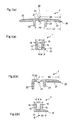
- Fig. 1 shows below Fig. 1 (a) an upper cover profile 2 and under Fig. 1 (b) a lower base profile 1 of a first embodiment of a cover according to the invention in a sectional view.
- the base profile 1 has a base plate 11, which can be fastened to a subfloor via a first screw connection.
- On the base plate 11 are laterally aligned with the base plate two rectangular upward leg 12 formed. Between the two legs 12 holes 13 in the base plate 11 are provided at regular intervals for attachment of the base profile 1 to a subfloor. The bore 13 partially break through the two legs 12 so that sufficiently large screws can be used for attachment to the subfloor.
- the two legs 12 form a channel 15, which serves for fastening the cover profile 2 on the base profile by means of a screw connection. Further, both legs 12 of the base profile 1 are substantially flat on the sides facing each other, so that a self-tapping screw for the second screw connection can cut a thread.
- the minimum width B of the channel 15 in the upper region between the two legs 12 of the base profile 1 is 1.8 to 2.5 mm, preferably about 2 mm.
- the two legs 12 have two outwardly directed projections 16 in the upper area. These allow the patch on the base profile 1 cover profile 2 a certain game, so that the cover profile 2 is also slightly beveled on the base profile 1 can be mounted.
- the base profile 1 has a height of 4 to 5 mm, preferably about 4.5 mm, and the two legs 12 of the base profile 1 have a length of 2 to 3.5 mm, preferably about 2.5 mm.
- the two legs 12 may also have two inwardly directed projections for the second screw (in Fig.1 (b) not shown).
- the bore 13 for the first screw would break the legs 12 only in the region of the inwardly directed projections.
- the cover profile 2 comprises a cover plate 21 on which a cover leg 23 is integrally formed on both sides.
- the cover profile with two deck legs has a total width of 20 to 35 mm, preferably 25 to 30, more preferably about 27 mm.
- Such a cover profile 2 serves to cover at transitions between two equally thick floor coverings.
- one of the two cover legs 23 ' can be angled downward at an angle of 15 to 25 degrees, as is the case in eg 3 (a) is shown.
- the cover legs (23, 23 ') preferably have a length L2 of 6 to 10 mm, preferably 7 to 8 mm.
- a web 24 Centered on the cover plate 21 of the cover profile 2 is a web 24 which points downwards at right angles and which has a width which is smaller than the minimum width B of the channel 15 in the upper region between the two legs 12 (or the inwardly directed projections). of the base profile is 1.
- the web 24 also serves to better hold the screw for the second screw.
- the length of the web 24 is 0.5 to 1.0 mm.
- two rectangular downwardly directed leg 22 are formed on the cover plate 21 of the cover profile 2, which have an inner distance A2, which is greater than an outer distance A1 of the two legs 12 of the base profile 1 by about 1.5 mm.
- the thickness of the legs 22 of the cover profile 2 is 1.6 to 2.5 mm, preferably 1.8 to 2.2 mm, more preferably about 2 mm.
- the cover profile 2 has centrally in the cover plate 21 has a bore 25, as for example in Fig. 2 (a) or Fig. 5 (c) is shown.
- the length of the legs 22 of the cover profile 2 correspond approximately to the length of the legs 12 of the base profile. 1
- the distance B1. defined by a plane of symmetry S between the two legs 12 of the base profile 1 and a laterally outermost edge 18 of the base plate 11, and distance B2 of the cover profile 2, defined by the bore 25 in the middle of the cover plate 21 and a laterally outermost edge 26 of the cover profile, has a ratio of 1: 2 to 1: 3, preferably about 1: 2.5.
- Fig. 2 shows a further embodiment of the cover strip according to the invention in a sectional view.
- 2 (a) shows an upper cover profile 2, which differs from the upper cover profile 2 1 (a) has only one deck leg 23.
- Such a cover profile is particularly suitable for edge finishes in floor coverings.
- Fig. 2 (b) shows a base profile 1, which differs from the base profile Fig. 1 (b) a base plate 11 which on one side over one of the two legs 12 by 1.8 to 3.3 mm, preferably about 2.5 mm, protrudes. This corresponds to about 1 to 1.5 times the thickness of the legs 12 of the base profile 1 and / or the legs 22 of the cover profile 2.
- the bore 13 for attachment of the base profile 1 on the subfloor can be carried out as below Fig.1 (b) described or it may be arranged centrally in the base plate 11 so that it breaks through only one of the two legs 12.
- the thickness of the legs 12 of the base profile 1 is 1.6 to 3.0 mm, preferably 1.8 to 2.5 mm, more preferably about 2.2 mm.
- the base plate 1 in the region which projects beyond the leg 12 of the base profile 11, in the longitudinal direction of the base profile 1 have holes or slots 14, such as in Figure 4 shown.
- the slots 14 are used in an additional sticking of the base profile 1 on the subfloor that an adhesive can pass through the slots 14, which ensures a better connection with the subfloor.
- the leg 22 ' may be formed extended.
- Fig. 3 shows a further embodiment of the cover strip according to the invention in a sectional view.
- 3 (a) shows an upper cover profile 2, in which, in contrast to the upper cover profile 2 off 1
- one of the two deck legs 23 is angled downward by 15 to 25 degrees relative to the other.
- Such a cover profile 2 serves to cover at transitions between two unevenly thick floor coverings.
- Fig. 3 (b) shows a base profile 1, which differs from the base profile Fig. 2 (b) a base plate 11 which protrudes on both sides over the two legs 12 by 1.8 to 3.3 mm, preferably about 2.5 mm.
- the hole for fixing the base profile 1 to the subfloor can in this case break through both legs 12, since sufficient stability in the longitudinal direction of the base profile is ensured by the base plate 11 protruding on both sides, such as in FIG Figure 4 shown.
- the thickness of the legs 12 of the base profile 1 is 1.6 to 3.0 mm, preferably 1.8 to 2.5 mm, more preferably about 2.2 mm.
- the slots 14 may be present on both sides.
- Fig. 4 shows a plan view of a section of a base profile 1 of a cover strip according to the invention as below Figure 3 (b) described.
- the slots 14 are disposed in the laterally projecting portions of the base plate 11. Centered in the base plate 11 holes 13 are arranged, which break through the legs 12 of the base profile 1. Between the two legs 12 of the channel 15 is formed for the second screw.
- Fig. 5 shows several application examples of the various embodiments of the base profile 1 and the cover profile 2 of the Fig. 1 to 3 together with the floor coverings in a sectional view (the screw connections are not shown).
- 5 (a) is a base profile 1 off Figure 3 (b) and a cover profile 2 off 1 (a) for the transition between two thin PVC or LVT design coverings 3 shown.
- the pads 3 have a thickness of less than 5 mm, usually only about 4 mm, up.
- the two deck legs 23 cover the joint 4 between the pad 3 and the base profile 1, with enough room for a lateral expansion of the pads 3 is still available.
- Fig. 5 (b) is different from 5 (a) a base profile 1 and a cover profile 2 off Fig. 3 for the transition between a thin PVC or LVT design coverings 3 and a much thicker parquet or laminate covering 3 'is shown, wherein one of the cover legs 23' relative to the other by 15 to 25 degrees down angled.
- the cover profile 2 is mounted higher relative to the base profile 1.
- only a longer screw for the second screw is necessary.
- the same profile strip can also be used in a transition from a thin covering to the subfloor. For this purpose, only the cover profile 2 is fastened lower with a shorter screw.
- Fig. 5 (c) is different from FIGS. 5 (a) and 5 (b) a base profile 1 and a cover profile 2 off Fig. 2 for the edge termination of a thin PVC or LVT design cover 3.
- the leg 22 'of the cover profile 2 is extended and extends to the subsoil.
- a screw 5 is shown for the second screw, which cuts a thread in the inside of the channel 15 formed by the legs 12 of the base profile 1.
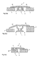
- Fig. 6 shows below Fig. 6 (a) an upper cover profile 2 and under Fig. 6 (b) a lower base profile 1 of a further embodiment of a cover strip according to the invention in a sectional view.
- the base profile 1 off Fig.1 (b) has the base profile 1 Fig. 6 (b) two obliquely converging legs 12, which have two inwardly directed projections 17 for the second screw in the upper region.
- a T-shaped channel 15 is formed, which has sufficient space for a bore 13 for the first screw in the lower region on the base plate.
- the bore 13 partially breaks through the legs 12 and the projections 17, as in FIG Fig. 6 (c) shown. Nevertheless, enough material is available for the stability of the base profile 1.
- This design is particularly advantageous because it can be dimensioned very small and through which the mold leads to material savings.
- Fig. 1 (a) In contrast to the cover profile 2 off Fig. 1 (a) has the cover profile 2 from Fig. 6 (a) no vertically downwardly directed leg.
- the web 24 is extended and has a length of 3.5 to 4.5 mm, preferably about 4.0 mm. It also assumes the function of lateral alignment.
- the web 24 may extend almost mounted to the base plate 11 of the base profile when mounted cover profile 2.
- the web 24, which is pierced by the bore 25 in the middle of the cover plate 21, as in Fig. 6 (d) shown ensures a good grip for the screw of the second screw.
- the cover legs of the cover profile 2 may be formed as in the above-described embodiments.
- a further embodiment of a base profile 1 of a cover strip according to the invention is shown in a sectional view.
- the base profile 1 corresponds to the base profile Fig. 3 (b) , where there is further a height pad 30, as in Fig. 10 shown includes.
- the base plate 11 protrudes beyond the two legs 12 and forms a notch or a shoulder 19 in the base profile.
- the height support 30 has two substantially parallel to the side surfaces of the base plate 11, upwardly directed webs 31.
- the two webs 31 have two inwardly directed lugs 32, which are arranged such that they can engage in each case in the notch or on the shoulder 19.
- the heights 30 of the Figs. 7 (a) and 7 (b) differ only in their thickness.
- a height support 30 may, for example, on the base profile 1 of the cover strip in Fig. 5 (b) be attached to bring base and cover profile closer together. As a result, the stability of the cover strip is increased.
- the base profile 1 can be inserted between the two webs 31 of the height support 30.
- the base profile 1 can also be pressed and latched between the two webs 31.
- the webs 31 of the height support for example, be 1 to 1.5 mm wide, so that in the assembled state, the base profile of the cover strip is only slightly widened.
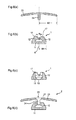
- Fig. 8 shows an embodiment of the inventive heel 30 with two webs 31 in a plan view.
- the height support 30 has in the base plate a plurality of recesses 33, preferably elongated holes, for the first screw for fixing the base profile 1 on the underbody.
- the elongated holes have the advantage that when mounting the base profile 1 more leeway is available to bring the holes 13 in the base profile 1 and the slots in the height support 30 in accordance.
- the base profile 1 can be bolted directly to the subfloor together with the height support 30.
- the webs 31 of the height support 30 have a certain flexibility, so that the base profile 1 between the two webs 31 of the height profile 30 can be engaged. In this way it is possible, only the Secure height support 30 to the underbody and then lock the base profile 1 to the height support 30.
- Fig. 9 shows under (a) to (c) further embodiments of the base profile 1 of the cover strip according to the invention in a sectional view.
- the base profiles 1 all have a shoulder 19 or a notch 19 on the upwardly directed legs 12.
- a height pad 30 can be brought into engagement with the shoulder 19 or with the notch 19 by inserting the base profile 1 or by engaging the base profile 1.
- Fig. 11 shows under (a) and (b) two further embodiments of a base profile of the cover strip according to the invention with a height support in a sectional view.
- the base profile has a fastening groove 34, preferably with an undercut.
- the height support 30 has a substantially upwardly directed web 31. This is substantially complementary to the mounting groove 34 and can be engaged with this.
- the fastening groove and bridge is formed with a round head.
- Fig. 11 (b) corresponds to the mounting groove and the web of a dovetail joint.
- the height support can be easily connected to the base profile by inserting or locking, for example, the web 31 may also have a latching nose, which can engage in the mounting groove.
- the height support can be formed the same width as the base plate of the base profile, so that the base profile with or without height support is the same width.
- Fig. 12 shows under (a) and (b) two further embodiments of a base profile of the cover strip according to the invention with a height support in a sectional view.
- the height pad in Fig. 12 (a) is formed as a plate and has recesses for the first screw on.
- Such a height support for example, can be screwed together with the base profile 1 on a subfloor and is therefore suitable for all the above-mentioned base profiles.
- the recesses may also be open towards the side edge of the height support, such as in Fig. 13 shown, so that the height support can be pushed laterally under a already partially bolted to the subfloor profile.
- a height support 30 is shown, which has a stop 35 on the lateral edge. This height support can also be screwed together with the base profile 1 on a subfloor or, if the recesses to the side are open, are pushed under an already partially bolted base profile.
Applications Claiming Priority (2)
| Application Number | Priority Date | Filing Date | Title |
|---|---|---|---|
| DE102012002095A DE102012002095A1 (de) | 2011-11-28 | 2012-02-06 | Abdeckleiste für Bodenbeläge |
| DE201220005602 DE202012005602U1 (de) | 2012-02-06 | 2012-06-11 | Höhenauflage für eine Abdeckleiste |
Publications (3)
| Publication Number | Publication Date |
|---|---|
| EP2623687A2 true EP2623687A2 (de) | 2013-08-07 |
| EP2623687A3 EP2623687A3 (de) | 2015-04-22 |
| EP2623687B1 EP2623687B1 (de) | 2017-01-11 |
Family
ID=47355453
Family Applications (1)
| Application Number | Title | Priority Date | Filing Date |
|---|---|---|---|
| EP13000568.9A Active EP2623687B1 (de) | 2012-02-06 | 2013-02-05 | Höhenauflage für eine Abdeckleiste |
Country Status (2)
| Country | Link |
|---|---|
| EP (1) | EP2623687B1 (es) |
| DE (1) | DE202012005602U1 (es) |
Families Citing this family (1)
| Publication number | Priority date | Publication date | Assignee | Title |
|---|---|---|---|---|
| DE102017009858A1 (de) * | 2017-10-24 | 2019-04-25 | Markus Claudius Proll | Variable Fugenabdeckvorrichtung |
Citations (2)
| Publication number | Priority date | Publication date | Assignee | Title |
|---|---|---|---|---|
| DE3743895A1 (de) | 1987-12-23 | 1989-07-13 | Herm Friedr Kuenne Fa | Abnehmbares ueberbrueckungsprofil fuer fussbodenfugen |
| AT2214U1 (de) | 1995-08-04 | 1998-06-25 | Franz Ernst Englisch | Abdeckvorrichtung für fussbodenbeläge |
Family Cites Families (6)
| Publication number | Priority date | Publication date | Assignee | Title |
|---|---|---|---|---|
| US2996751A (en) * | 1958-09-09 | 1961-08-22 | Stanley Works | Snap-on molding |
| DE9412987U1 (de) * | 1994-08-11 | 1994-10-27 | Seis Helmut | Profilschienensystem zum Überbrücken von Fugen oder Rändern bei Belägen |
| DE29924459U1 (de) * | 1999-10-26 | 2003-04-17 | Kuenne Hermann Friedrich Gmbh | Fugenüberbrückungsanordnung |
| US7207143B2 (en) * | 2001-11-08 | 2007-04-24 | Pergo (Europe) Ab | Transition molding and installation methods therefor |
| US8747596B2 (en) * | 2005-01-12 | 2014-06-10 | Flooring Industries Limited, Sarl | Finishing set for floor covering and holder, as well as finishing profile, for a finishing set, and method for manufacturing a finishing profile and a skirting board |
| GB0626007D0 (en) * | 2006-12-29 | 2007-02-07 | Whiting Richard A | Engaging assembly for a floor covering |
-
2012
- 2012-06-11 DE DE201220005602 patent/DE202012005602U1/de not_active Expired - Lifetime
-
2013
- 2013-02-05 EP EP13000568.9A patent/EP2623687B1/de active Active
Patent Citations (2)
| Publication number | Priority date | Publication date | Assignee | Title |
|---|---|---|---|---|
| DE3743895A1 (de) | 1987-12-23 | 1989-07-13 | Herm Friedr Kuenne Fa | Abnehmbares ueberbrueckungsprofil fuer fussbodenfugen |
| AT2214U1 (de) | 1995-08-04 | 1998-06-25 | Franz Ernst Englisch | Abdeckvorrichtung für fussbodenbeläge |
Also Published As
| Publication number | Publication date |
|---|---|
| EP2623687B1 (de) | 2017-01-11 |
| EP2623687A3 (de) | 2015-04-22 |
| DE202012005602U1 (de) | 2012-11-12 |
Similar Documents
| Publication | Publication Date | Title |
|---|---|---|
| EP1527241B1 (de) | Vorrichtung zum verbinden von zwei plattenförmigen paneelen | |
| DE102007043308B4 (de) | Einrichtung zur Verbindung und Verriegelung zweier Bauplatten, insbesondere Fussbodenpaneele | |
| EP1294995B1 (de) | Fussbodensystem mit mehreren gleichen Fussbodenplatten | |
| EP1437454B1 (de) | Höhenverstellbarer Eckkantenschutz | |
| EP2270291B1 (de) | Satz aus Bauplatten mit einer Einrichtung zum Verriegeln zweier dieser Bauplatten | |
| EP2446097B1 (de) | FUßBODENPROFILANORDNUNG | |
| DE202014006016U1 (de) | Montageklammer | |
| DE202012104033U1 (de) | Haltevorrichtung für eine Brüstungs- oder Geländerplatte sowie Geländer oder Brüstung mit Scheibe | |
| DE10233105A1 (de) | Profilelement mit Verbindungsteilen für mechanische Steckverbindungen und damit geschaffener Profilelementenverbund | |
| DE19730600A1 (de) | Stulpschienenbeschlag | |
| DE102006042052B4 (de) | Isolierplattendübel | |
| EP1439278A2 (de) | Dichtung, insbesondere Auflaufdichtung oder sich selbsttätig absenkende Bodendichtung für Türen mit einstellbarer Befestigung | |
| EP2623687B1 (de) | Höhenauflage für eine Abdeckleiste | |
| EP2845965B1 (de) | Befestigung von Bohlen an einer Unterkonstruktion | |
| EP3692611B1 (de) | Anordnung zur positionierung eines flachteils an einem schaltschrankrahmengestell sowie ein entsprechendes verfahren | |
| EP2884036B1 (de) | Dichtung umfassend wenigstens einen Befestigungswinkel und wenigstens einen Anschlag zur Montage an der Kante einer Nut in einem Türblatt o. ä. | |
| DE102012002095A1 (de) | Abdeckleiste für Bodenbeläge | |
| DE202013010369U1 (de) | Montageelement für Dielen, Fliesen oder dergleichen | |
| EP1826331A2 (de) | Montagehilfe und Pfosten-Riegel-Konstruktion | |
| DE102011120118B4 (de) | Beschlag | |
| EP3450649A1 (de) | Befestigungsprofil | |
| DE102012205047B4 (de) | Steckverbinderelement und Steckverbindungssystem zur Verbindung zweier Bauteile | |
| EP2020513B1 (de) | Beschlag zum Verbinden zweier Möbelplatten | |
| DE202015104298U1 (de) | Verbindungselement | |
| DE10354310A1 (de) | Dichtung insbesondere selbsttätig absenkende Bodendichtung für Türen |
Legal Events
| Date | Code | Title | Description |
|---|---|---|---|
| PUAI | Public reference made under article 153(3) epc to a published international application that has entered the european phase |
Free format text: ORIGINAL CODE: 0009012 |
|
| AK | Designated contracting states |
Kind code of ref document: A2 Designated state(s): AL AT BE BG CH CY CZ DE DK EE ES FI FR GB GR HR HU IE IS IT LI LT LU LV MC MK MT NL NO PL PT RO RS SE SI SK SM TR |
|
| AX | Request for extension of the european patent |
Extension state: BA ME |
|
| PUAL | Search report despatched |
Free format text: ORIGINAL CODE: 0009013 |
|
| AK | Designated contracting states |
Kind code of ref document: A3 Designated state(s): AL AT BE BG CH CY CZ DE DK EE ES FI FR GB GR HR HU IE IS IT LI LT LU LV MC MK MT NL NO PL PT RO RS SE SI SK SM TR |
|
| AX | Request for extension of the european patent |
Extension state: BA ME |
|
| RIC1 | Information provided on ipc code assigned before grant |
Ipc: E04F 19/06 20060101AFI20150318BHEP |
|
| 17P | Request for examination filed |
Effective date: 20151019 |
|
| RBV | Designated contracting states (corrected) |
Designated state(s): AL AT BE BG CH CY CZ DE DK EE ES FI FR GB GR HR HU IE IS IT LI LT LU LV MC MK MT NL NO PL PT RO RS SE SI SK SM TR |
|
| GRAP | Despatch of communication of intention to grant a patent |
Free format text: ORIGINAL CODE: EPIDOSNIGR1 |
|
| INTG | Intention to grant announced |
Effective date: 20160928 |
|
| GRAS | Grant fee paid |
Free format text: ORIGINAL CODE: EPIDOSNIGR3 |
|
| GRAA | (expected) grant |
Free format text: ORIGINAL CODE: 0009210 |
|
| AK | Designated contracting states |
Kind code of ref document: B1 Designated state(s): AL AT BE BG CH CY CZ DE DK EE ES FI FR GB GR HR HU IE IS IT LI LT LU LV MC MK MT NL NO PL PT RO RS SE SI SK SM TR |
|
| REG | Reference to a national code |
Ref country code: GB Ref legal event code: FG4D Free format text: NOT ENGLISH |
|
| REG | Reference to a national code |
Ref country code: CH Ref legal event code: EP |
|
| REG | Reference to a national code |
Ref country code: AT Ref legal event code: REF Ref document number: 861443 Country of ref document: AT Kind code of ref document: T Effective date: 20170115 |
|
| REG | Reference to a national code |
Ref country code: IE Ref legal event code: FG4D Free format text: LANGUAGE OF EP DOCUMENT: GERMAN |
|
| REG | Reference to a national code |
Ref country code: DE Ref legal event code: R096 Ref document number: 502013006024 Country of ref document: DE |
|
| REG | Reference to a national code |
Ref country code: LT Ref legal event code: MG4D |
|
| REG | Reference to a national code |
Ref country code: NL Ref legal event code: MP Effective date: 20170111 |
|
| PG25 | Lapsed in a contracting state [announced via postgrant information from national office to epo] |
Ref country code: BE Free format text: LAPSE BECAUSE OF NON-PAYMENT OF DUE FEES Effective date: 20170228 |
|
| PG25 | Lapsed in a contracting state [announced via postgrant information from national office to epo] |
Ref country code: NL Free format text: LAPSE BECAUSE OF FAILURE TO SUBMIT A TRANSLATION OF THE DESCRIPTION OR TO PAY THE FEE WITHIN THE PRESCRIBED TIME-LIMIT Effective date: 20170111 |
|
| PG25 | Lapsed in a contracting state [announced via postgrant information from national office to epo] |
Ref country code: IS Free format text: LAPSE BECAUSE OF FAILURE TO SUBMIT A TRANSLATION OF THE DESCRIPTION OR TO PAY THE FEE WITHIN THE PRESCRIBED TIME-LIMIT Effective date: 20170511 Ref country code: FI Free format text: LAPSE BECAUSE OF FAILURE TO SUBMIT A TRANSLATION OF THE DESCRIPTION OR TO PAY THE FEE WITHIN THE PRESCRIBED TIME-LIMIT Effective date: 20170111 Ref country code: HR Free format text: LAPSE BECAUSE OF FAILURE TO SUBMIT A TRANSLATION OF THE DESCRIPTION OR TO PAY THE FEE WITHIN THE PRESCRIBED TIME-LIMIT Effective date: 20170111 Ref country code: NO Free format text: LAPSE BECAUSE OF FAILURE TO SUBMIT A TRANSLATION OF THE DESCRIPTION OR TO PAY THE FEE WITHIN THE PRESCRIBED TIME-LIMIT Effective date: 20170411 Ref country code: GR Free format text: LAPSE BECAUSE OF FAILURE TO SUBMIT A TRANSLATION OF THE DESCRIPTION OR TO PAY THE FEE WITHIN THE PRESCRIBED TIME-LIMIT Effective date: 20170412 Ref country code: LT Free format text: LAPSE BECAUSE OF FAILURE TO SUBMIT A TRANSLATION OF THE DESCRIPTION OR TO PAY THE FEE WITHIN THE PRESCRIBED TIME-LIMIT Effective date: 20170111 |
|
| PG25 | Lapsed in a contracting state [announced via postgrant information from national office to epo] |
Ref country code: ES Free format text: LAPSE BECAUSE OF FAILURE TO SUBMIT A TRANSLATION OF THE DESCRIPTION OR TO PAY THE FEE WITHIN THE PRESCRIBED TIME-LIMIT Effective date: 20170111 Ref country code: PL Free format text: LAPSE BECAUSE OF FAILURE TO SUBMIT A TRANSLATION OF THE DESCRIPTION OR TO PAY THE FEE WITHIN THE PRESCRIBED TIME-LIMIT Effective date: 20170111 Ref country code: SE Free format text: LAPSE BECAUSE OF FAILURE TO SUBMIT A TRANSLATION OF THE DESCRIPTION OR TO PAY THE FEE WITHIN THE PRESCRIBED TIME-LIMIT Effective date: 20170111 Ref country code: LV Free format text: LAPSE BECAUSE OF FAILURE TO SUBMIT A TRANSLATION OF THE DESCRIPTION OR TO PAY THE FEE WITHIN THE PRESCRIBED TIME-LIMIT Effective date: 20170111 Ref country code: RS Free format text: LAPSE BECAUSE OF FAILURE TO SUBMIT A TRANSLATION OF THE DESCRIPTION OR TO PAY THE FEE WITHIN THE PRESCRIBED TIME-LIMIT Effective date: 20170111 Ref country code: BG Free format text: LAPSE BECAUSE OF FAILURE TO SUBMIT A TRANSLATION OF THE DESCRIPTION OR TO PAY THE FEE WITHIN THE PRESCRIBED TIME-LIMIT Effective date: 20170411 Ref country code: PT Free format text: LAPSE BECAUSE OF FAILURE TO SUBMIT A TRANSLATION OF THE DESCRIPTION OR TO PAY THE FEE WITHIN THE PRESCRIBED TIME-LIMIT Effective date: 20170511 |
|
| REG | Reference to a national code |
Ref country code: DE Ref legal event code: R097 Ref document number: 502013006024 Country of ref document: DE |
|
| PG25 | Lapsed in a contracting state [announced via postgrant information from national office to epo] |
Ref country code: RO Free format text: LAPSE BECAUSE OF FAILURE TO SUBMIT A TRANSLATION OF THE DESCRIPTION OR TO PAY THE FEE WITHIN THE PRESCRIBED TIME-LIMIT Effective date: 20170111 Ref country code: SK Free format text: LAPSE BECAUSE OF FAILURE TO SUBMIT A TRANSLATION OF THE DESCRIPTION OR TO PAY THE FEE WITHIN THE PRESCRIBED TIME-LIMIT Effective date: 20170111 Ref country code: CZ Free format text: LAPSE BECAUSE OF FAILURE TO SUBMIT A TRANSLATION OF THE DESCRIPTION OR TO PAY THE FEE WITHIN THE PRESCRIBED TIME-LIMIT Effective date: 20170111 Ref country code: EE Free format text: LAPSE BECAUSE OF FAILURE TO SUBMIT A TRANSLATION OF THE DESCRIPTION OR TO PAY THE FEE WITHIN THE PRESCRIBED TIME-LIMIT Effective date: 20170111 Ref country code: IT Free format text: LAPSE BECAUSE OF FAILURE TO SUBMIT A TRANSLATION OF THE DESCRIPTION OR TO PAY THE FEE WITHIN THE PRESCRIBED TIME-LIMIT Effective date: 20170111 |
|
| PLBE | No opposition filed within time limit |
Free format text: ORIGINAL CODE: 0009261 |
|
| STAA | Information on the status of an ep patent application or granted ep patent |
Free format text: STATUS: NO OPPOSITION FILED WITHIN TIME LIMIT |
|
| REG | Reference to a national code |
Ref country code: IE Ref legal event code: MM4A |
|
| PG25 | Lapsed in a contracting state [announced via postgrant information from national office to epo] |
Ref country code: DK Free format text: LAPSE BECAUSE OF FAILURE TO SUBMIT A TRANSLATION OF THE DESCRIPTION OR TO PAY THE FEE WITHIN THE PRESCRIBED TIME-LIMIT Effective date: 20170111 Ref country code: SM Free format text: LAPSE BECAUSE OF FAILURE TO SUBMIT A TRANSLATION OF THE DESCRIPTION OR TO PAY THE FEE WITHIN THE PRESCRIBED TIME-LIMIT Effective date: 20170111 Ref country code: MC Free format text: LAPSE BECAUSE OF FAILURE TO SUBMIT A TRANSLATION OF THE DESCRIPTION OR TO PAY THE FEE WITHIN THE PRESCRIBED TIME-LIMIT Effective date: 20170111 |
|
| REG | Reference to a national code |
Ref country code: FR Ref legal event code: ST Effective date: 20171031 |
|
| 26N | No opposition filed |
Effective date: 20171012 |
|
| GBPC | Gb: european patent ceased through non-payment of renewal fee |
Effective date: 20170411 |
|
| PG25 | Lapsed in a contracting state [announced via postgrant information from national office to epo] |
Ref country code: LU Free format text: LAPSE BECAUSE OF NON-PAYMENT OF DUE FEES Effective date: 20170205 |
|
| PG25 | Lapsed in a contracting state [announced via postgrant information from national office to epo] |
Ref country code: FR Free format text: LAPSE BECAUSE OF NON-PAYMENT OF DUE FEES Effective date: 20170313 |
|
| REG | Reference to a national code |
Ref country code: BE Ref legal event code: MM Effective date: 20170228 |
|
| PG25 | Lapsed in a contracting state [announced via postgrant information from national office to epo] |
Ref country code: SI Free format text: LAPSE BECAUSE OF FAILURE TO SUBMIT A TRANSLATION OF THE DESCRIPTION OR TO PAY THE FEE WITHIN THE PRESCRIBED TIME-LIMIT Effective date: 20170111 Ref country code: IE Free format text: LAPSE BECAUSE OF NON-PAYMENT OF DUE FEES Effective date: 20170205 Ref country code: GB Free format text: LAPSE BECAUSE OF NON-PAYMENT OF DUE FEES Effective date: 20170411 |
|
| PG25 | Lapsed in a contracting state [announced via postgrant information from national office to epo] |
Ref country code: MT Free format text: LAPSE BECAUSE OF FAILURE TO SUBMIT A TRANSLATION OF THE DESCRIPTION OR TO PAY THE FEE WITHIN THE PRESCRIBED TIME-LIMIT Effective date: 20170111 |
|
| PG25 | Lapsed in a contracting state [announced via postgrant information from national office to epo] |
Ref country code: HU Free format text: LAPSE BECAUSE OF FAILURE TO SUBMIT A TRANSLATION OF THE DESCRIPTION OR TO PAY THE FEE WITHIN THE PRESCRIBED TIME-LIMIT; INVALID AB INITIO Effective date: 20130205 |
|
| PG25 | Lapsed in a contracting state [announced via postgrant information from national office to epo] |
Ref country code: CY Free format text: LAPSE BECAUSE OF NON-PAYMENT OF DUE FEES Effective date: 20170111 |
|
| PG25 | Lapsed in a contracting state [announced via postgrant information from national office to epo] |
Ref country code: MK Free format text: LAPSE BECAUSE OF FAILURE TO SUBMIT A TRANSLATION OF THE DESCRIPTION OR TO PAY THE FEE WITHIN THE PRESCRIBED TIME-LIMIT Effective date: 20170111 |
|
| PG25 | Lapsed in a contracting state [announced via postgrant information from national office to epo] |
Ref country code: TR Free format text: LAPSE BECAUSE OF FAILURE TO SUBMIT A TRANSLATION OF THE DESCRIPTION OR TO PAY THE FEE WITHIN THE PRESCRIBED TIME-LIMIT Effective date: 20170111 |
|
| PG25 | Lapsed in a contracting state [announced via postgrant information from national office to epo] |
Ref country code: AL Free format text: LAPSE BECAUSE OF FAILURE TO SUBMIT A TRANSLATION OF THE DESCRIPTION OR TO PAY THE FEE WITHIN THE PRESCRIBED TIME-LIMIT Effective date: 20170111 |
|
| PGFP | Annual fee paid to national office [announced via postgrant information from national office to epo] |
Ref country code: AT Payment date: 20220217 Year of fee payment: 10 |
|
| PGFP | Annual fee paid to national office [announced via postgrant information from national office to epo] |
Ref country code: DE Payment date: 20230216 Year of fee payment: 11 |
|
| P01 | Opt-out of the competence of the unified patent court (upc) registered |
Effective date: 20230602 |
|
| REG | Reference to a national code |
Ref country code: AT Ref legal event code: MM01 Ref document number: 861443 Country of ref document: AT Kind code of ref document: T Effective date: 20230205 |
|
| PG25 | Lapsed in a contracting state [announced via postgrant information from national office to epo] |
Ref country code: AT Free format text: LAPSE BECAUSE OF NON-PAYMENT OF DUE FEES Effective date: 20230205 |
|
| PGFP | Annual fee paid to national office [announced via postgrant information from national office to epo] |
Ref country code: CH Payment date: 20230712 Year of fee payment: 11 |