EP2641783A2 - Battery pack and method of controlling the same - Google Patents
Battery pack and method of controlling the same Download PDFInfo
- Publication number
- EP2641783A2 EP2641783A2 EP13155809.0A EP13155809A EP2641783A2 EP 2641783 A2 EP2641783 A2 EP 2641783A2 EP 13155809 A EP13155809 A EP 13155809A EP 2641783 A2 EP2641783 A2 EP 2641783A2
- Authority
- EP
- European Patent Office
- Prior art keywords
- sleep mode
- current
- battery
- load
- control unit
- Prior art date
- Legal status (The legal status is an assumption and is not a legal conclusion. Google has not performed a legal analysis and makes no representation as to the accuracy of the status listed.)
- Granted
Links
Images


Classifications
-
- H—ELECTRICITY
- H01—ELECTRIC ELEMENTS
- H01M—PROCESSES OR MEANS, e.g. BATTERIES, FOR THE DIRECT CONVERSION OF CHEMICAL ENERGY INTO ELECTRICAL ENERGY
- H01M10/00—Secondary cells; Manufacture thereof
- H01M10/42—Methods or arrangements for servicing or maintenance of secondary cells or secondary half-cells
-
- B—PERFORMING OPERATIONS; TRANSPORTING
- B60—VEHICLES IN GENERAL
- B60L—PROPULSION OF ELECTRICALLY-PROPELLED VEHICLES; SUPPLYING ELECTRIC POWER FOR AUXILIARY EQUIPMENT OF ELECTRICALLY-PROPELLED VEHICLES; ELECTRODYNAMIC BRAKE SYSTEMS FOR VEHICLES IN GENERAL; MAGNETIC SUSPENSION OR LEVITATION FOR VEHICLES; MONITORING OPERATING VARIABLES OF ELECTRICALLY-PROPELLED VEHICLES; ELECTRIC SAFETY DEVICES FOR ELECTRICALLY-PROPELLED VEHICLES
- B60L58/00—Methods or circuit arrangements for monitoring or controlling batteries or fuel cells, specially adapted for electric vehicles
- B60L58/10—Methods or circuit arrangements for monitoring or controlling batteries or fuel cells, specially adapted for electric vehicles for monitoring or controlling batteries
- B60L58/12—Methods or circuit arrangements for monitoring or controlling batteries or fuel cells, specially adapted for electric vehicles for monitoring or controlling batteries responding to state of charge [SoC]
- B60L58/15—Preventing overcharging
-
- B—PERFORMING OPERATIONS; TRANSPORTING
- B60—VEHICLES IN GENERAL
- B60L—PROPULSION OF ELECTRICALLY-PROPELLED VEHICLES; SUPPLYING ELECTRIC POWER FOR AUXILIARY EQUIPMENT OF ELECTRICALLY-PROPELLED VEHICLES; ELECTRODYNAMIC BRAKE SYSTEMS FOR VEHICLES IN GENERAL; MAGNETIC SUSPENSION OR LEVITATION FOR VEHICLES; MONITORING OPERATING VARIABLES OF ELECTRICALLY-PROPELLED VEHICLES; ELECTRIC SAFETY DEVICES FOR ELECTRICALLY-PROPELLED VEHICLES
- B60L58/00—Methods or circuit arrangements for monitoring or controlling batteries or fuel cells, specially adapted for electric vehicles
- B60L58/10—Methods or circuit arrangements for monitoring or controlling batteries or fuel cells, specially adapted for electric vehicles for monitoring or controlling batteries
- B60L58/12—Methods or circuit arrangements for monitoring or controlling batteries or fuel cells, specially adapted for electric vehicles for monitoring or controlling batteries responding to state of charge [SoC]
- B60L58/14—Preventing excessive discharging
-
- B—PERFORMING OPERATIONS; TRANSPORTING
- B60—VEHICLES IN GENERAL
- B60R—VEHICLES, VEHICLE FITTINGS, OR VEHICLE PARTS, NOT OTHERWISE PROVIDED FOR
- B60R16/00—Electric or fluid circuits specially adapted for vehicles and not otherwise provided for; Arrangement of elements of electric or fluid circuits specially adapted for vehicles and not otherwise provided for
- B60R16/02—Electric or fluid circuits specially adapted for vehicles and not otherwise provided for; Arrangement of elements of electric or fluid circuits specially adapted for vehicles and not otherwise provided for electric constitutive elements
- B60R16/03—Electric or fluid circuits specially adapted for vehicles and not otherwise provided for; Arrangement of elements of electric or fluid circuits specially adapted for vehicles and not otherwise provided for electric constitutive elements for supply of electrical power to vehicle subsystems or for
-
- H—ELECTRICITY
- H01—ELECTRIC ELEMENTS
- H01M—PROCESSES OR MEANS, e.g. BATTERIES, FOR THE DIRECT CONVERSION OF CHEMICAL ENERGY INTO ELECTRICAL ENERGY
- H01M10/00—Secondary cells; Manufacture thereof
- H01M10/42—Methods or arrangements for servicing or maintenance of secondary cells or secondary half-cells
- H01M10/46—Accumulators structurally combined with charging apparatus
-
- H—ELECTRICITY
- H01—ELECTRIC ELEMENTS
- H01M—PROCESSES OR MEANS, e.g. BATTERIES, FOR THE DIRECT CONVERSION OF CHEMICAL ENERGY INTO ELECTRICAL ENERGY
- H01M10/00—Secondary cells; Manufacture thereof
- H01M10/42—Methods or arrangements for servicing or maintenance of secondary cells or secondary half-cells
- H01M10/48—Accumulators combined with arrangements for measuring, testing or indicating the condition of cells, e.g. the level or density of the electrolyte
-
- H—ELECTRICITY
- H02—GENERATION; CONVERSION OR DISTRIBUTION OF ELECTRIC POWER
- H02J—CIRCUIT ARRANGEMENTS OR SYSTEMS FOR SUPPLYING OR DISTRIBUTING ELECTRIC POWER; SYSTEMS FOR STORING ELECTRIC ENERGY
- H02J7/00—Circuit arrangements for charging or depolarising batteries or for supplying loads from batteries
- H02J7/0063—Circuit arrangements for charging or depolarising batteries or for supplying loads from batteries with circuits adapted for supplying loads from the battery
-
- H—ELECTRICITY
- H02—GENERATION; CONVERSION OR DISTRIBUTION OF ELECTRIC POWER
- H02J—CIRCUIT ARRANGEMENTS OR SYSTEMS FOR SUPPLYING OR DISTRIBUTING ELECTRIC POWER; SYSTEMS FOR STORING ELECTRIC ENERGY
- H02J7/00—Circuit arrangements for charging or depolarising batteries or for supplying loads from batteries
- H02J7/007—Regulation of charging or discharging current or voltage
- H02J7/00712—Regulation of charging or discharging current or voltage the cycle being controlled or terminated in response to electric parameters
-
- H—ELECTRICITY
- H01—ELECTRIC ELEMENTS
- H01M—PROCESSES OR MEANS, e.g. BATTERIES, FOR THE DIRECT CONVERSION OF CHEMICAL ENERGY INTO ELECTRICAL ENERGY
- H01M10/00—Secondary cells; Manufacture thereof
- H01M10/42—Methods or arrangements for servicing or maintenance of secondary cells or secondary half-cells
- H01M10/425—Structural combination with electronic components, e.g. electronic circuits integrated to the outside of the casing
- H01M2010/4271—Battery management systems including electronic circuits, e.g. control of current or voltage to keep battery in healthy state, cell balancing
-
- H—ELECTRICITY
- H01—ELECTRIC ELEMENTS
- H01M—PROCESSES OR MEANS, e.g. BATTERIES, FOR THE DIRECT CONVERSION OF CHEMICAL ENERGY INTO ELECTRICAL ENERGY
- H01M2220/00—Batteries for particular applications
- H01M2220/20—Batteries in motive systems, e.g. vehicle, ship, plane
-
- H—ELECTRICITY
- H02—GENERATION; CONVERSION OR DISTRIBUTION OF ELECTRIC POWER
- H02J—CIRCUIT ARRANGEMENTS OR SYSTEMS FOR SUPPLYING OR DISTRIBUTING ELECTRIC POWER; SYSTEMS FOR STORING ELECTRIC ENERGY
- H02J2310/00—The network for supplying or distributing electric power characterised by its spatial reach or by the load
- H02J2310/40—The network being an on-board power network, i.e. within a vehicle
- H02J2310/46—The network being an on-board power network, i.e. within a vehicle for ICE-powered road vehicles
-
- H—ELECTRICITY
- H02—GENERATION; CONVERSION OR DISTRIBUTION OF ELECTRIC POWER
- H02J—CIRCUIT ARRANGEMENTS OR SYSTEMS FOR SUPPLYING OR DISTRIBUTING ELECTRIC POWER; SYSTEMS FOR STORING ELECTRIC ENERGY
- H02J7/00—Circuit arrangements for charging or depolarising batteries or for supplying loads from batteries
- H02J7/14—Circuit arrangements for charging or depolarising batteries or for supplying loads from batteries for charging batteries from dynamo-electric generators driven at varying speed, e.g. on vehicle
-
- Y—GENERAL TAGGING OF NEW TECHNOLOGICAL DEVELOPMENTS; GENERAL TAGGING OF CROSS-SECTIONAL TECHNOLOGIES SPANNING OVER SEVERAL SECTIONS OF THE IPC; TECHNICAL SUBJECTS COVERED BY FORMER USPC CROSS-REFERENCE ART COLLECTIONS [XRACs] AND DIGESTS
- Y02—TECHNOLOGIES OR APPLICATIONS FOR MITIGATION OR ADAPTATION AGAINST CLIMATE CHANGE
- Y02E—REDUCTION OF GREENHOUSE GAS [GHG] EMISSIONS, RELATED TO ENERGY GENERATION, TRANSMISSION OR DISTRIBUTION
- Y02E60/00—Enabling technologies; Technologies with a potential or indirect contribution to GHG emissions mitigation
- Y02E60/10—Energy storage using batteries
-
- Y—GENERAL TAGGING OF NEW TECHNOLOGICAL DEVELOPMENTS; GENERAL TAGGING OF CROSS-SECTIONAL TECHNOLOGIES SPANNING OVER SEVERAL SECTIONS OF THE IPC; TECHNICAL SUBJECTS COVERED BY FORMER USPC CROSS-REFERENCE ART COLLECTIONS [XRACs] AND DIGESTS
- Y02—TECHNOLOGIES OR APPLICATIONS FOR MITIGATION OR ADAPTATION AGAINST CLIMATE CHANGE
- Y02T—CLIMATE CHANGE MITIGATION TECHNOLOGIES RELATED TO TRANSPORTATION
- Y02T10/00—Road transport of goods or passengers
- Y02T10/60—Other road transportation technologies with climate change mitigation effect
- Y02T10/70—Energy storage systems for electromobility, e.g. batteries
-
- Y—GENERAL TAGGING OF NEW TECHNOLOGICAL DEVELOPMENTS; GENERAL TAGGING OF CROSS-SECTIONAL TECHNOLOGIES SPANNING OVER SEVERAL SECTIONS OF THE IPC; TECHNICAL SUBJECTS COVERED BY FORMER USPC CROSS-REFERENCE ART COLLECTIONS [XRACs] AND DIGESTS
- Y02—TECHNOLOGIES OR APPLICATIONS FOR MITIGATION OR ADAPTATION AGAINST CLIMATE CHANGE
- Y02T—CLIMATE CHANGE MITIGATION TECHNOLOGIES RELATED TO TRANSPORTATION
- Y02T10/00—Road transport of goods or passengers
- Y02T10/80—Technologies aiming to reduce greenhouse gasses emissions common to all road transportation technologies
- Y02T10/92—Energy efficient charging or discharging systems for batteries, ultracapacitors, supercapacitors or double-layer capacitors specially adapted for vehicles
Abstract
Description
- The present invention relates to a battery pack and a method of controlling the same.
- Unlike primary batteries, secondary batteries may be charged and discharged. Second batteries are used as energy sources in mobile devices, electric cars, hybrid cars, electric bicycles, uninterruptible power supply apparatuses, and the like, and are used in the form of single batteries or a battery module comprising a plurality of batteries in a single unit, depending on the type of the device.
- Typically, a lead storage battery is used as a power supply for starting up an engine. Recently, an idle stop & go (ISG) system for improving fuel efficiency has been increasingly used. In spite of the output properties and frequent starting-up of a power supply for supporting an ISG system for restricting a no-load operation, the discharge properties of the power supply need to be maintained and a long lifetime of the power supply needs to be ensured. However, since an engine of a typical lead storage battery is repeatedly stopped and started up under an ISG system, the charge and discharge properties of the lead storage battery may deteriorate.
- The present invention provides a battery pack according to
claim 1, and a method of operating a vehicle under an idle stop and go system according toclaim 10. - Preferred aspects of the invention are defined in
claims 2 to 9 and 11 to 15. -
-
FIG. 1 is a diagram of a structure of a vehicle in which a battery pack is mounted according to an embodiment of the present invention; -
FIG. 2 is a diagram of a structure of a battery pack according to an embodiment of the present invention; -
FIG. 3 is a graph of an output voltage of a first terminal with respect to a resistance value of a variable resistor according to an embodiment of the present invention; -
FIG. 4 is a diagram of a structure of a battery pack according to another embodiment of the present invention; -
FIG. 5 is a diagram of a structure of a vehicle according to another embodiment of the present invention; -
FIG. 6 is a diagram of a structure of a battery pack according to another embodiment of the present invention; -
FIG. 7 is a diagram of a structure of a vehicle according to another embodiment of the present invention; -
FIG. 8 is a diagram of a structure of a battery pack according to another embodiment of the present invention; -
FIG. 9 is a diagram of a structure of a battery pack according to another embodiment of the present invention; and -
FIG. 10 is a diagram of a structure of a battery pack according to another embodiment of the present invention. - The attached drawings for illustrating preferred embodiments of the present invention are referred to in order to gain a sufficient understanding of the present invention, the merits thereof, and the objectives accomplished by the implementation of the present invention. The invention may, however, be embodied in many different forms and should not be construed as being limited to the embodiments set forth herein; rather, these embodiments are provided so that this disclosure will be thorough and complete, and will fully convey the concept of the invention to those skilled in the art. Meanwhile, the terms used in the present specification are merely used to describe particular embodiments, and are not intended to limit the present invention. An expression used in the singular encompasses the expression of the plural, unless it has a clearly different meaning in the context, In the present specification, it is to be understood that the terms such as "including" or "having," etc., are intended to indicate the existence of the features, numbers, steps, actions, components, parts, or combinations thereof disclosed in the specification, and are not intended to preclude the possibility that one or more other features, numbers, steps, actions, components, parts, or combinations thereof may exist or may be added. While such terms as "first," "second," etc., may be used to describe various components, such components must not be limited to the above terms. The above terms are used only to distinguish one component from another.
- The present invention aims to control a sleep mode current generated in a sleep mode in which an engine of a car, an electric bicycle, etc. including a battery pack does not start, by using simple components inside the battery pack. The battery pack provides a function of controlling the sleep mode current to further inactivate a function of a main control unit of the car, the electric bicycle, etc. in the sleep mode and reduce power consumption,
-
FIG. 1 is a diagram of a structure of avehicle 10 in which abattery pack 100 is mounted according to an embodiment of the present invention. - The
battery pack 100 according to an embodiment of the present invention is mounted in thevehicle 10 including an engine (not shown). Thevehicle 10 may be, for example, a car, an electric bicycle, etc. - The
battery pack 100 stores charging power generated by apower generation module 110 and supplies discharged power to astarter motor 120. Thepower generation module 110 is connected to a driving axis of the engine to convert rotational power into an electric output. In this regard, the charging power generated by thepower generation module 110 is supplied to thebattery pack 100. For example, thepower generation module 110 may include a DC generator (not shown) or an AC generator (not shown) and a rectifier (not shown), and may supply a DC voltage of about DC 15V, more particularly, a DC voltage of about 14.6V to about 14.8V. - The
starter motor 120 operates when the engine starts, and provides initial rotational power used to rotate the driving axis of the engine. Thestarter motor 120 receives stored power through first and second terminals P1 and P2 of thebattery pack 100 and rotates the driving axis when the engine operates or when the engine operates again after an idle stop to start the engine. Thestarter motor 120 operates when the engine starts. Thepower generation module 110 operates and generates the charging power when the engine that is started by thestarter motor 120 is running. - The
battery pack 100 is provided in a power supply apparatus for starting an engine of an idle stop & go (ISG) system that implements an ISG function so as to better fuel efficiency. The engine of the ISG system frequently repeats stopping and restarting, and thus thebattery pack 100 is repeatedly charged and discharged. - Since a lead storage battery used in a typical ISG system is repeatedly charged and discharged, a service life of the lead storage battery is reduced and the charging and discharging properties of the lead storage battery deteriorate. As the lead storage battery is repeatedly charged and discharged, start capability of the engine deteriorates and the lead storage battery requires frequently exchanging.
- According to an embodiment of the present invention the
battery pack 100 includes a lithium ion battery that has charging and discharging properties that are maintained relatively constant and hardly deteriorate along with service time, compared to a lead storage battery. The battery unit 105 may therefore be used in an ISG system whose engine is repeatedly stopped and started up. Thebattery pack 100 has a low weight and improved fuel efficiency, compared to a lead storage battery having the same discharge capacity. In addition, thebattery pack 100 uses a smaller volume than that of a lead storage battery with the same charging capacity, thereby reducing a loading space. However, thebattery pack 100 is not limited to a lithium ion battery and may be, for example, a nickel metal hydride battery (NiMH) or the like. - At least one electrical load is connected to the
battery pack 100, together with thepower generation module 110 and thestarter motor 120. The at least one electrical load is exemplified as anelectrical load 1 130a and anelectrical load 2 130b in the present specification. The number of and the types of the electrical loads may vary. Theelectrical load 1 130a and theelectrical load 2 130b consume power stored in thebattery pack 100 and receive stored discharging power through the first and second terminals P1 and P2. Theelectrical load 1 130a and theelectrical load 2 130b may be a variety of types of electric apparatuses such as a navigation apparatus, an audio, a lighting apparatus, a car black box, an anti-theft apparatus, and the like. - The
main control unit 140 is a control unit for controlling an overall operation of thevehicle 10 in which thebattery pack 100 is mounted. Themain control unit 140 is connected to thebattery pack 100 through a third terminal P3, exchanges a control signal with thebattery pack 100, monitors a status of thebattery pack 100, and controls an operation of thebattery pack 100. - The
vehicle 10 operates in a driving mode when thevehicle 10 starts and in a sleep mode when thevehicle 10 does not start. An operating mode of thevehicle 10 is set and controlled by themain control unit 140. Themain control unit 140 also controls thebattery pack 100, theelectrical load 1 130a and theelectrical load 2 130b, and elements of thevehicle 10 according to the operating mode of thevehicle 10. - The
battery pack 100 is charged using charging power supplied by thepower generation module 110 and discharges to supply electricity to thestarter motor 120 and theelectrical load 1 130a and theelectrical load 2 130b in the driving mode. Thebattery pack 100 does not perform the charging operation and supplies a current to theelectrical load 1 130a and theelectrical load 2 130b in the sleep mode. The current supplied to theelectrical load 1 130a and theelectrical load 2 130b in the sleep mode is referred to as a sleep mode current. Thebattery pack 100 consumes power in the sleep mode by using the sleep mode current. - The power stored in the
battery pack 100 is supplied to thestarter motor 120 in order to start the engine again when the sleep mode is changed to the driving mode, i.e. when the engine of thevehicle 10 starts. However, in a case where no driving power is supplied to thestarter motor 120 since thebattery pack 100 is discharged in the sleep mode due to the sleep mode current, it is likely that thevehicle 10 does not start again. - Embodiments of the present invention provide a function of controlling the sleep mode current of the
battery pack 100 in order to block the sleep mode current. Also, a variable resistor may be used to control the sleep mode current. Therefore, the sleep mode current is controlled by using a simple structure. -
FIG. 2 is a diagram of a structure of abattery pack 100a according to an embodiment of the present invention. - The
battery pack 100a according to an embodiment of the present invention includes abattery cell 210, a first sleep modecurrent control unit 220, and a battery management system (BMS) 230. - The
battery cell 210 may be implemented as a lithium ion battery, an NiMH or the like. Thebattery cell 210 is charged with a charging current supplied from thepower generation module 110. Thebattery cell 210 supplies the charged power to thestarter motor 120 and theelectrical load 1 130a and theelectrical load 2 130b. - A charging and discharging path of the
battery cell 210 and a path through which a sleep mode current flows in a sleep mode are commonly formed so that a charging and discharging current and the sleep mode current flow by using the first sleep modecurrent control unit 220. - The first sleep mode
current control unit 220 includes a variable resistor. A resistance value of the variable resistor varies with a control signal received from theBMS 230. TheBMS 230 may control the resistance value of the variable resistor according to a current mode of thevehicle 10. For example, theBMS 230 sets the resistance value of the variable resistor as a first resistance value used to form the charging and discharging path if the current mode is a driving mode, and sets it as a second resistance value used to form the sleep mode current path if the current mode is the sleep mode. In this regard, the first resistance value is smaller than the second resistance value. - According to another embodiment of the present invention, the
BMS 230 may control the resistance value of the variable resistor in the sleep mode. For example, theBMS 230 detects a voltage of thebattery cell 210 in the sleep mode, controls the resistance value of the variable resistor according to the voltage of thebattery cell 210, and controls the sleep mode current. In this case, the lower the voltage of thebattery cell 210, the greater the resistance value of the variable resistor, and thus the sleep mode current may be reduced in a case where the charging power of thebattery cell 210 becomes small. -
FIG. 3 is a graph of an output voltage of the first terminal P1 with respect to a resistance value of a variable resistor according to an embodiment of the present invention. - Referring to
FIG. 3 , the greater the resistance value of the variable resistor, the smaller the output voltage of the first terminal P1. A relationship between the resistance value of the variable resistor and the output voltage of the first terminal P1 is used to turn electrical loads off step by step. For example, the resistance value of the variable resistor is controlled to three steps of R1, R2, and R3 in a sleep mode. If the output voltage of the first terminal P1 is changed to V1, V2, and V3 according to the change of the resistance value of the variable resistor, electrical loads are automatically turned off according to rating voltage levels thereof. For example, in a case where the resistance value of the variable resistor is R1, and the output voltage of the first terminal P1 is V1,electrical loads 1 through 5 having rating voltage levels lower than V1 are all turned on. In a case where the resistance value of the variable resistor is R2, and the output voltage of the first terminal P1 is V2, theelectrical loads electrical loads 3 through 5 are turned on. In a case where the resistance value of the variable resistor is R3, and the output voltage of the first terminal P1 is V3, theelectrical loads 1 through 4 having rating voltage levels higher than V3 are all turned off, and theelectrical load 5 is turned on. Also, the resistance value of the variable resistor may be set as a maximum value or the variable resistor may be turned off in order to block the sleep mode current. - According to an embodiment of the present invention, the variable resistor may have a predetermined discontinuous number of resistance values in order to turn the
electrical loads 1 through 5 off step by step. -
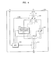
FIG. 4 is a diagram of a structure of abattery pack 100b according to another embodiment of the present invention. - The
battery pack 100b according to this embodiment of the present invention may include thebattery cell 210, the first sleep modecurrent control unit 220, theBMS 230, a charging and dischargingunit 410, and amode control unit 420. - The
battery pack 100b separately includes a charging and discharging path I1 and a first sleep mode current path I2. The first terminal P1 is connected to thebattery cell 210 through the charging and discharging path I1 or through the first sleep mode current path I2 according to an operating mode of thevehicle 10. The charging and discharging path I1 is a path connected to the charging and dischargingunit 410. The first sleep mode current path I2 is a path connected to the first sleep modecurrent control unit 220. - The charging and discharging
unit 410 forms the charging and discharging path I1 when thevehicle 10 is in a driving mode. The charging and dischargingunit 410 may be implemented to include a conductor. According to another embodiment, the charging and dischargingunit 410 may be implemented to include a resistor. According to another embodiment, the charging and dischargingunit 410 may be implemented to include a switch. According to another embodiment, the charging and dischargingunit 410 may be implemented to include a charging path and a discharging path in parallel. In this case, each of the charging path and the discharging path may include a diode. - The first sleep mode
current control unit 220 forms the first sleep mode current path I2 when thevehicle 10 is in a sleep mode. As described above, the first sleep modecurrent control unit 220 includes a variable resistor. A resistance value of the variable resistor is controlled by theBMS 230. - The
mode control unit 420 connects the charging and discharging path I1 to the first terminal P1 or the first sleep mode current path I2 to the second terminal P2 according to the operating mode of thevehicle 10. A control signal CON used to control themode control unit 420 may be provided by theBMS 230. - In a case where the
vehicle 10 is in the driving mode, themode control unit 420 has a first status in which the switch is connected to a terminal S1. Thus, a current output from thebattery cell 210 is electrically connected to the first terminal P1 through the charging and dischargingunit 410. If thepower generation module 110 supplies a charging current through the first terminal P1 in the driving mode, the charging current is supplied to thebattery cell 210 through the charging and dischargingunit 410. - In a case where the
vehicle 10 is in the sleep mode, themode control unit 420 has a second status in which the switch is connected to a terminal S2. Thus, the current output from thebattery cell 210 is supplied to electrical loads through the first sleep modecurrent control unit 220 and the first terminal P1. As described above, the resistance value of the variable resistor of the first sleep modecurrent control unit 220 varies with respect to voltage levels of thebattery cell 210 in the sleep mode. Also, the resistance value of the variable resistor of the first sleep modecurrent control unit 220 is controlled by theBMS 230 in the sleep mode. -
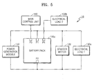
FIG. 5 is a diagram of a structure of thevehicle 10 according to another embodiment of the present invention. - The
vehicle 10 according to another embodiment of the present invention includes electrical loads that are not allowed to be turned off even in a sleep mode. Abattery pack 100c provides a fourth terminal P4 to which a current is supplied all the time even in the sleep mode. According to such a structure, a designer of thevehicle 10 connects electrical loads that are not allowed to be turned off even in the sleep mode to the fourth terminal P4 so that corresponding electrical loads may not be turned off even in the sleep mode. - For example, as shown in
FIG. 5 , theelectrical load 1 130a is connected to the first terminal P1 to stop operating according to an output voltage level of the first terminal P1 in the sleep mode, whereas theelectrical load 2 130b is connected to the fourth terminal P4 to operate even in the sleep mode. -
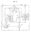
FIG, 6 is a diagram of a structure of thebattery pack 100c according to another embodiment of the present invention. - The
battery pack 100c includes thebattery cell 210, the first sleep modecurrent control unit 220, theBMS 230, the charging and discharging unit 4'10, themode control unit 420, and a second sleep modecurrent control unit 610. - The second sleep mode
current control unit 610 is connected between thebattery cell 210 and the fourth terminal P4 to form a second sleep modecurrent path 13. - The second sleep mode
current control unit 610 may be implemented to include a conductor. In this case, power is supplied to an electrical load connected to the fourth terminal P4 through the second sleep mode current path I3 in a driving mode and sleep mode all the time, and thus power is more reliably supplied to the electrical load, and the electrical mode may be turned on even in the sleep mode. - The second sleep mode
current control unit 610 may be implemented to include a switch, wherein the switch of the second sleep modecurrent control unit 610 is turned on in the driving mode and sleep mode, and is turned off if it is detected that thebattery pack 100c is in a dangerous status. For example, in a case where thebattery pack 100c is overheated, overcharged, over-discharged, and is likely to explode in the sleep mode, the second sleep modecurrent control unit 610 may be turned off. Also, in a case where remaining power of thebattery cell 210 approaches or reaches a restriction level by which thestarter motor 120 may operate once in the sleep mode, the second sleep modecurrent control unit 610 may change the switch thereof to an off status to wholly block a sleep mode current. A control signal used to control the second sleep modecurrent control unit 610 is provided by theBMS 230. Also, if it is detected that thebattery pack 100c is in the dangerous status, the first sleep mode current path I2 may also be blocked. -
FIG. 7 is a diagram of a structure of thevehicle 10 according to another embodiment of the present invention. - Referring to
FIG. 7 , thevehicle 10 includes at least one electrical load, i.e. theelectrical load 1 130a and theelectrical load 2 130b, connected to abattery pack 100d through respective terminals of thebattery pack 100d. That is, thebattery pack 100d provides theelectrical load 1 130a with the fourth terminal P4 for supplying power and theelectrical load 2 130b with the fifth terminal P5 for supplying power. Thus, thepower generation module 110 and thestarter motor 120 are connected to the first terminal P1 and charging and discharging current flow in the first terminal P1, and theelectrical load 1 130a and theelectrical load 2 130b are respectively connected to the fourth terminal P4 and the fifth terminal P5 and a current for driving theelectrical load 1 130a and theelectrical load 2 130b and a sleep mode current flow in the fourth terminal P4 and the fifth terminal P5. - According to the above-described structure of the
vehicle 10, a plurality of electrical loads may be individually controlled to be turned on/off. Also, instead of turning the electrical loads off step by step according to rating voltage levels, the electrical loads may be turned off step by step according to an importance or an intensity of a sleep mode current. - A method of blocking a sleep mode current that flows in a plurality of electrical loads will now be described in detail.
-
FIG. 8 is a diagram of a structure of abattery pack 100d' according to another embodiment of the present invention. - Referring to
FIG. 8 , thebattery pack 100d' includes thebattery cell 210, the first sleep modecurrent control unit 220, theBMS 230, a charging and dischargingunit 410, and a third sleep modecurrent control unit 810. - The first sleep mode
current control unit 220 is connected between thebattery cell 210 and the fourth terminal P4 to form a fourth sleep modecurrent path 14. Likewise, the third sleep modecurrent control unit 810 is connected between thebattery cell 210 and the fifth terminal P5 to form a fifth sleep modecurrent path 15. - The
BMS 230 controls variable resistance values of the first sleep modecurrent control unit 220 and the third sleep modecurrent control unit 810 to be reduced in a driving mode, and thus power consumption of a variable resistor may be minimized. - Meanwhile, the
BMS 230 controls the variable resistance values according to a voltage of thebattery cell 210 in a sleep mode. TheBMS 230 controls the variable resistance values to be greater in the sleep mode than in the driving mode. Further, theBMS 230 may increase the variable resistance values as the voltage of thebattery cell 210 is reduced, and thus, a sleep mode current may be reduced if charging power of thebattery cell 210 is reduced. - In particular, the
BMS 230 of thebattery pack 100d' may separately control the variable resistance values of the first sleep modecurrent control unit 220 and the third sleep modecurrent control unit 810. Accordingly, power may be supplied to one of theelectrical load 1 130a and theelectrical load 2 130b, and may not be supplied to the other one. That is, power may be supplied to only a desired electrical load according to a user's request. For example, it may be determined whether to supply power or not according to an importance of a load, and an amount of power consumption. - In a case where remaining power of the
battery cell 210 approaches or reaches a restriction level by which thestarter motor 120 may operate once from the voltage of thebattery cell 210, theBMS 230 may minimize or wholly block the sleep mode current by setting the maximum variable resistance values of the first sleep modecurrent control unit 220 and the third sleep modecurrent control unit 810. -
FIG. 9 is a diagram of a structure of abattery pack 100d" according to another embodiment of the present invention. Differences between thebattery pack 100d" according to the present embodiment and thebattery pack 100d' ofFIG. 8 will be described below. - Referring to
FIG. 9 , thebattery pack 100d" includes thebattery cell 210, the first sleep modecurrent control unit 220, theBMS 230, the charging and dischargingunit 410, the third sleep modecurrent control unit 810, asensor 1 910, and asensor 2 920. - The
sensor 1 910 and the first sleep modecurrent control unit 220 are connected in series to each other between thebattery cell 210 and the fourth terminal P4 to form the fourth sleep modecurrent path 14. An arrangement sequence of thesensor 1 910 and the first sleep modecurrent control unit 220 may change. Likewise, thesensor 2 920 and the third sleep modecurrent control unit 810 are connected to each other between thebattery cell 210 and the fifth terminal P5 to form the fifth sleep modecurrent path 15. - The
sensor 1 910 and thesensor 2 920 respectively sense intensities of two currents that flow in the fourth sleep mode current path I4 and the fifth sleep mode current path I5. Thesensor 1 910 and thesensor 2 920 transmit sensing results to theBMS 230. - The
BMS 230 may separately control variable resistance values of the first sleep modecurrent control unit 220 and the third sleep modecurrent control unit 810 based on the sensing results of current received from thesensor 1 910 and thesensor 2 920. TheBMS 230 may block a sleep mode current path in a case where a sleep mode current value is greater than a reference value. For example, in a case where an intensity of a sleep mode current sensed by thesensor 1 910 is greater than the reference value, theBMS 230 may minimize or block power supply to theelectrical load 1 130a by setting the maximum variable resistance value of the first sleep modecurrent control unit 220. - The
BMS 230 may control the variable resistance values of the first sleep modecurrent control unit 220 and the third sleep modecurrent control unit 810 step by step based on the sensing results of current received from thesensor 1 910 and thesensor 2 920 and a voltage of thebattery cell 210. In this regard, theBMS 230 may include a plurality of reference values used to control resistance values by a plurality of steps. Each of the reference values may be determined according to the voltage of thebattery cell 210. For example, if the voltage of thebattery cell 210 has a first voltage value, and the intensity of the sleep mode current is greater than a first reference value, theBMS 230 controls the intensity of the sleep mode current to be smaller than the first reference value by increasing the variable resistance values of the first sleep modecurrent control unit 220 and the third sleep modecurrent control unit 810. If the voltage of thebattery cell 210 is reduced to have a second voltage value, and the intensity of the sleep mode current is greater than a second reference value, theBMS 230 controls the intensity of the sleep mode current to be smaller than the second reference value by further increasing the variable resistance values of the first sleep modecurrent control unit 220 and the third sleep modecurrent control unit 810. In this regard, the second reference value is smaller than the first reference value. - Also, in the present embodiment, in a case where remaining power of the
battery cell 210 approaches or reaches a restriction level by which thestarter motor 120 may operate once from the voltage of thebattery cell 210, if the intensity of the sleep mode current is greater than a minimum reference value, theBMS 230 may minimize or wholly block the sleep mode current by setting the maximum variable resistance values of the first sleep modecurrent control unit 220 and the third sleep modecurrent control unit 810. -
FIG. 10 is a diagram of a structure of abattery pack 100d"' according to another embodiment of the present invention. Differences between thebattery pack 100d"' according to the present embodiment and thebattery pack 100d" ofFIG. 9 will be described below. - Referring to
FIG. 10 , thebattery pack 100d"' includes thebattery cell 210, the first sleep modecurrent control unit 220, theBMS 230, the charging and dischargingunit 410, the third sleep modecurrent control unit 810, thesensor 1 910, thesensor 2 920, aswitch 1 1010, and aswitch 2 1020. - The
sensor 1 910, the first sleep modecurrent control unit 220, and theswitch 1 1010 are connected in series to each other between thebattery cell 210 and the fourth terminal P4 to form the fourth sleep mode current path I4. An arrangement sequence of thesensor 1 910, the first sleep modecurrent control unit 220, and theswitch 1 1010 may change. Likewise, thesensor 2 920, the third sleep modecurrent control unit 810, and theswitch 2 1020 are connected to each other between thebattery cell 210 and the fifth terminal P5 to form the fifth sleep modecurrent path 15. - The
switch 1 1010 and theswitch 2 1020 may be used to wholly block the fourth sleep mode current path I4 and the fifth sleep mode current path I5, respectively. Even if the first sleep modecurrent control unit 220 and the third sleep modecurrent control unit 810 have the maximum variable resistance values, a sleep mode current weakly flows, which causes unnecessary power consumption of thebattery cell 210. Thus, to wholly block the fourth sleep mode current path I4 and the fifth sleep modecurrent path 15, theBMS 230 opens theswitch 1 1010 and/or theswitch 2 1020 to wholly block a sleep mode current. - Although not shown, the
battery packs 100d'∼100d"' ofFIGS. 8 through 10 may further include a mode control unit in a node to which the first sleep modecurrent control unit 220, the charging and dischargingunit 410, and the third sleep modecurrent control unit 810 are connected. Thebattery cell 210 may be connected to the charging and dischargingunit 410 in a driving mode and to the first sleep modecurrent control unit 220 and the third sleep modecurrent control unit 810 in a sleep mode. - Alternatively, the
battery cell 210 may be connected to the first sleep modecurrent control unit 220, the charging and dischargingunit 410, and the third sleep modecurrent control unit 810 in the driving mode and to the first sleep modecurrent control unit 220 and the third sleep modecurrent control unit 810 in the sleep mode. - While the present invention has been particularly shown and described with reference to embodiments thereof, it will be understood by one of ordinary skill in the art that various changes in form and details may be made therein without departing from the scope of the present invention as defined by the following claims.
Claims (15)
- A battery pack comprising:a rechargeable battery (210) configured to receive charging current from a power generation module (110) in a driving mode, to supply discharging current to a starter motor (120) in a start mode and to supply discharging current to at least one load (130a, 130b) in a sleep mode, wherein charging current is not received from the power generation module in the sleep mode;a current control unit (220) configured to control the current supplied to the at least one load; anda battery management system (230) configured to monitor an output voltage of the rechargeable battery in the sleep mode and control the current control unit to control the current supplied to the at least one load in the sleep mode based on the monitored output voltage.
- A battery pack according to claim 1, wherein the battery management system is configured to control the current control unit to reduce the current supplied to the at least one load as the monitored output voltage of the battery decreases.
- A battery pack according to claim 1 or 2, wherein the battery management system is configured to control the current control unit to cut off the current supplied to the at least one load when the monitored output voltage of the battery decreases to a predetermined threshold.
- A battery pack according to any one of the preceding claims, wherein the current control unit includes a variable resistor, wherein the battery management system controls the current supplied to the at least one load by varying a resistance value of the variable resistor.
- A battery pack according to any one of the preceding claims, wherein the rechargeable battery is connected to a driving mode path and a sleep mode path, wherein the current control unit is included in the sleep mode path, wherein the battery management system controls a switch such that an output terminal of the battery pack is connected to the driving mode path in the driving mode, and to the sleep mode path in the sleep mode.
- A battery pack according to any one of the preceding claims, including a terminal for connecting to a further load wherein a current is always supplied to the further load even in the sleep mode.
- A battery pack according to any one of the preceding claims, configured to supply current to a plurality of loads, wherein each load has an associated current control unit, and wherein the battery management system is configured to independently control each current control unit to control the current supplied to each load in the sleep mode based on the monitored output voltage of the battery.
- A battery pack according to any one of the preceding claims, further comprising a sensor configured to sense the current supplied to the at least one load and feed back to the battery management system, wherein the battery management system controls the current control unit to control the current supplied to the at least one load in the sleep mode based on the sensed current.
- A vehicle comprising:a battery pack according to any one of the preceding claims;a starter motor (120) configured to receive discharging power from the battery pack to start the engine; anda power generation module (110) configured to convert mechanical energy into electrical energy during an operation of the engine to supply charging power to the rechargeable battery.
- A method of operating a vehicle under an idle stop & go (ISG) system, comprising:supplying discharging current from a rechargeable battery to a starter motor (120) in a start mode to start an engine;generating charging current from the engine and supplying the charging current to the rechargeable battery (210) in a driving mode;supplying discharging current to at least one load (130a, 130b) in a sleep mode, wherein during the sleep mode the engine is off and charging current is not received by the battery;monitoring an output voltage of the rechargeable battery in the sleep mode and controlling the current supplied to the at least one load in the sleep mode based on the monitored output voltage.
- A method according to claim 10, wherein the current supplied to the at least one load in the sleep mode is reduced as the monitored output voltage of the battery decreases.
- A method according to claim 10 or 11, wherein the current supplied to the at least one load in the sleep mode is cut off when the monitored output voltage of the battery decreases to a predetermined threshold.
- A method according to any one of claims 10 to 12, wherein the current supplied to the at least one load is controlled by varying a resistance value of a variable resistor.
- A method according to any one of claims 10 to 13, comprising supplying current from the rechargeable battery to a plurality of loads in the sleep mode and independently controlling the current supplied to each load in the sleep mode based on the monitored output voltage of the battery.
- A method according to any one of claims 10 to 14, further comprising sensing the current supplied to the at least one load and controlling the current supplied to the at least one load in the sleep mode based on the sensed current.
Applications Claiming Priority (1)
| Application Number | Priority Date | Filing Date | Title |
|---|---|---|---|
| US201261613163P | 2012-03-20 | 2012-03-20 |
Publications (3)
| Publication Number | Publication Date |
|---|---|
| EP2641783A2 true EP2641783A2 (en) | 2013-09-25 |
| EP2641783A3 EP2641783A3 (en) | 2014-05-21 |
| EP2641783B1 EP2641783B1 (en) | 2016-04-20 |
Family
ID=47739139
Family Applications (1)
| Application Number | Title | Priority Date | Filing Date |
|---|---|---|---|
| EP13155809.0A Active EP2641783B1 (en) | 2012-03-20 | 2013-02-19 | Battery pack and method of controlling the same |
Country Status (4)
| Country | Link |
|---|---|
| US (1) | US9350189B2 (en) |
| EP (1) | EP2641783B1 (en) |
| JP (1) | JP6238427B2 (en) |
| KR (1) | KR102016752B1 (en) |
Cited By (5)
| Publication number | Priority date | Publication date | Assignee | Title |
|---|---|---|---|---|
| WO2016131708A1 (en) * | 2015-02-18 | 2016-08-25 | Audi Ag | Method for operating battery cells of a battery, battery and motor vehicle |
| FR3061369A1 (en) * | 2016-12-22 | 2018-06-29 | Commissariat A L'energie Atomique Et Aux Energies Alternatives | SECURING A LITHIUM BATTERY |
| EP3429056A1 (en) * | 2017-02-13 | 2019-01-16 | O2Micro, Inc. | Systems and methods for managing a battery pack |
| EP3462199A3 (en) * | 2017-09-21 | 2019-05-01 | Samsung SDI Co., Ltd. | Battery pack diagnostic apparatus |
| CN111176187A (en) * | 2020-01-08 | 2020-05-19 | 合肥阳光电动力科技有限公司 | Power management system and protection method of motor controller |
Families Citing this family (17)
| Publication number | Priority date | Publication date | Assignee | Title |
|---|---|---|---|---|
| KR101397023B1 (en) * | 2012-03-23 | 2014-05-20 | 삼성에스디아이 주식회사 | Battery pack and method for controlling the same |
| EP2645527A1 (en) * | 2012-03-26 | 2013-10-02 | Samsung SDI Co., Ltd. | Battery pack |
| US10106038B2 (en) * | 2012-12-28 | 2018-10-23 | Johnson Controls Technology Company | Dual function battery system and method |
| WO2016143400A1 (en) | 2015-03-12 | 2016-09-15 | オムロン株式会社 | Battery, system, battery damage detection device, battery management method, battery management program, and recording medium |
| WO2016143399A1 (en) | 2015-03-12 | 2016-09-15 | オムロン株式会社 | Battery, system, battery management method, battery management program, and recording medium |
| US10680436B2 (en) * | 2015-08-24 | 2020-06-09 | Nec Corporation | Constant current supply device, constant current supply system, and constant current supply method |
| DE102016214484A1 (en) * | 2016-08-04 | 2018-02-08 | Audi Ag | Method for preparing a battery of a motor vehicle for a transport and motor vehicle |
| KR101821327B1 (en) * | 2017-05-30 | 2018-01-24 | 콘티넨탈 오토모티브 게엠베하 | Input circuit capable of reducing dark current |
| KR102348118B1 (en) * | 2017-06-15 | 2022-01-07 | 현대자동차주식회사 | Apparatus for controlling dark current of vehicle and method thereof |
| KR102500690B1 (en) * | 2017-09-18 | 2023-02-17 | 삼성전자주식회사 | Battery status based charging control method and appratus thereof |
| WO2019130424A1 (en) * | 2017-12-26 | 2019-07-04 | 本田技研工業株式会社 | Battery device |
| JP2020145655A (en) * | 2019-03-08 | 2020-09-10 | 株式会社デンソー | Energization control device |
| CN110828923B (en) * | 2019-11-18 | 2022-03-01 | 北京小米移动软件有限公司 | Battery charging method, device and medium |
| KR102336746B1 (en) * | 2020-01-20 | 2021-12-06 | 경성대학교 산학협력단 | Power control circuit of renewable energy source |
| US11465506B2 (en) * | 2020-06-10 | 2022-10-11 | Ford Global Technologies, Llc | Systems and methods for controlling a high-output DCAC inverter on a vehicle |
| US11420523B2 (en) * | 2020-09-25 | 2022-08-23 | GM Global Technology Operations LLC | Enhanced electric drive vehicle operation via pulse width modulation (PWM) type and frequency control |
| EP4099474A4 (en) * | 2020-11-03 | 2024-01-10 | Lg Energy Solution Ltd | Battery rack management apparatus |
Family Cites Families (33)
| Publication number | Priority date | Publication date | Assignee | Title |
|---|---|---|---|---|
| US4902956A (en) * | 1986-12-12 | 1990-02-20 | Sloan Jeffrey M | Safety device to prevent excessive battery drain |
| US5293076A (en) | 1991-04-16 | 1994-03-08 | Mitsubishi Denki Kabushiki Kaisha | Vehicle control apparatus |
| JPH0769142A (en) | 1993-09-03 | 1995-03-14 | Yazaki Corp | Electric driving device for automobile |
| JP3699284B2 (en) * | 1999-01-18 | 2005-09-28 | 三菱電機株式会社 | Idling stop and start vehicle generator control device |
| JP3732038B2 (en) * | 1999-03-03 | 2006-01-05 | 株式会社井澤電子工業 | Auto engine stop method |
| DE19952112A1 (en) * | 1999-10-29 | 2001-06-07 | Audi Ag | Circuit arrangement to reduce rest current of idle vehicle; has devices to determine battery charge state and vehicle operation state and individual control units for number of electrical users |
| JP2001313199A (en) | 2000-04-26 | 2001-11-09 | Joshin Uramoto | Method of generating neutorino from battery and capacitor |
| US6759760B2 (en) | 2002-06-21 | 2004-07-06 | Daimlerchrysler Corporation | Method to eliminate shipping fuse handling |
| JP2004106621A (en) * | 2002-09-17 | 2004-04-08 | Nissan Motor Co Ltd | Automatic stopping/automatic restarting device for engine |
| KR20040037443A (en) | 2002-10-28 | 2004-05-07 | 한국전력공사 | Non-contact automatic voltage regulator for light buoy |
| US7231994B2 (en) * | 2003-11-24 | 2007-06-19 | Daimlerchrysler Corporation | Hybrid vehicle with integral generator for auxiliary loads |
| US7525287B2 (en) * | 2004-10-08 | 2009-04-28 | Husqvarna Zenoah Co., Ltd. | Battery pack for driving electric motor of compact engine starting device, engine starting device driven by the battery pack, and manual working machine having the engine starting device |
| WO2007100378A2 (en) * | 2005-12-23 | 2007-09-07 | Reinier Hoogenraad | Hybrid golf car |
| JP2007216817A (en) * | 2006-02-16 | 2007-08-30 | Fujitsu Ten Ltd | Power supply limiting device, and control device |
| DE102007026164A1 (en) * | 2007-06-04 | 2008-12-11 | Ipgate Ag | Electrical supply system for motor vehicle, has battery charging ultra cap by direct current-direct current converter before start of vehicle on high stress than rated stress, where stress level of electrical system is determined |
| JP4618277B2 (en) * | 2007-07-24 | 2011-01-26 | 株式会社デンソー | Power management system |
| JP2009096383A (en) * | 2007-10-18 | 2009-05-07 | Denso Corp | Management device for vehicular power source |
| US8091659B2 (en) * | 2007-12-27 | 2012-01-10 | Byd Co. Ltd. | Hybrid vehicle having engageable clutch assembly coupled between engine and traction motor |
| KR100995075B1 (en) | 2008-08-26 | 2010-11-18 | 삼성에스디아이 주식회사 | Battery management system and driving method thereof |
| JP2010138763A (en) * | 2008-12-10 | 2010-06-24 | Toyota Motor Corp | Power supply device for idling stop vehicle |
| KR20100116447A (en) | 2009-04-22 | 2010-11-01 | 한국단자공업 주식회사 | Apparatus and method for cutting off dark current |
| JP5394823B2 (en) * | 2009-05-28 | 2014-01-22 | 日清紡ホールディングス株式会社 | Charge control device, capacitor module, and charge control method |
| KR101036085B1 (en) * | 2009-09-08 | 2011-05-23 | 삼성에스디아이 주식회사 | Method of charging battery pack and battery pack |
| US8593112B2 (en) * | 2009-11-03 | 2013-11-26 | Samsung Sdi Co., Ltd. | Battery pack |
| SE537378C2 (en) * | 2010-03-25 | 2015-04-14 | Int Truck Intellectual Prop Co | Battery power management system |
| KR101084217B1 (en) * | 2010-03-29 | 2011-11-17 | 삼성에스디아이 주식회사 | Battery pack, and method for controlling the battery pack |
| US20110248678A1 (en) * | 2010-04-13 | 2011-10-13 | GRRREEN, Inc., a Delaware corporation | Intelligent battery management system and method |
| US8602141B2 (en) * | 2010-04-05 | 2013-12-10 | Daimler Trucks North America Llc | Vehicle power system with fuel cell auxiliary power unit (APU) |
| KR101108188B1 (en) * | 2010-06-10 | 2013-03-08 | 삼성에스디아이 주식회사 | Battery protection circuit and controlling method of the same |
| JP2012002168A (en) * | 2010-06-18 | 2012-01-05 | Toyota Motor Corp | Starter for internal combustion engine |
| US8525477B2 (en) | 2010-07-15 | 2013-09-03 | O2Micro, Inc. | Assigning addresses to multiple cascade battery modules in electric or electric hybrid vehicles |
| KR20120060108A (en) * | 2010-12-01 | 2012-06-11 | 현대자동차주식회사 | ISG System and Control Method thereof |
| CN202006735U (en) | 2011-01-04 | 2011-10-12 | 上海理工大学 | Disc-free braking system |
-
2013
- 2013-02-19 EP EP13155809.0A patent/EP2641783B1/en active Active
- 2013-03-05 US US13/785,021 patent/US9350189B2/en active Active
- 2013-03-15 KR KR1020130028234A patent/KR102016752B1/en active IP Right Grant
- 2013-03-18 JP JP2013055454A patent/JP6238427B2/en active Active
Non-Patent Citations (1)
| Title |
|---|
| None |
Cited By (11)
| Publication number | Priority date | Publication date | Assignee | Title |
|---|---|---|---|---|
| WO2016131708A1 (en) * | 2015-02-18 | 2016-08-25 | Audi Ag | Method for operating battery cells of a battery, battery and motor vehicle |
| CN107278188A (en) * | 2015-02-18 | 2017-10-20 | 奥迪股份公司 | For method, battery and the motor vehicle of the battery cell for running battery |
| CN107278188B (en) * | 2015-02-18 | 2018-09-11 | 奥迪股份公司 | Method, battery and the motor vehicle of battery cell for running battery |
| FR3061369A1 (en) * | 2016-12-22 | 2018-06-29 | Commissariat A L'energie Atomique Et Aux Energies Alternatives | SECURING A LITHIUM BATTERY |
| EP3429056A1 (en) * | 2017-02-13 | 2019-01-16 | O2Micro, Inc. | Systems and methods for managing a battery pack |
| US10886753B2 (en) | 2017-02-13 | 2021-01-05 | O2Micro Inc. | Systems and methods for managing a battery pack |
| US11362522B2 (en) | 2017-02-13 | 2022-06-14 | O2Micro Inc. | Systems and methods for managing a battery pack |
| EP3462199A3 (en) * | 2017-09-21 | 2019-05-01 | Samsung SDI Co., Ltd. | Battery pack diagnostic apparatus |
| US10916814B2 (en) | 2017-09-21 | 2021-02-09 | Samsung Sdi Co., Ltd. | Battery pack diagnostic apparatus for analyzing a state of a battery pack according to various measurement values |
| CN111176187A (en) * | 2020-01-08 | 2020-05-19 | 合肥阳光电动力科技有限公司 | Power management system and protection method of motor controller |
| CN111176187B (en) * | 2020-01-08 | 2022-07-12 | 合肥阳光电动力科技有限公司 | Power management system and protection method of motor controller |
Also Published As
| Publication number | Publication date |
|---|---|
| KR20130106782A (en) | 2013-09-30 |
| JP6238427B2 (en) | 2017-11-29 |
| US9350189B2 (en) | 2016-05-24 |
| EP2641783A3 (en) | 2014-05-21 |
| JP2013193738A (en) | 2013-09-30 |
| EP2641783B1 (en) | 2016-04-20 |
| KR102016752B1 (en) | 2019-08-30 |
| US20130249492A1 (en) | 2013-09-26 |
Similar Documents
| Publication | Publication Date | Title |
|---|---|---|
| EP2641783B1 (en) | Battery pack and method of controlling the same | |
| KR101397023B1 (en) | Battery pack and method for controlling the same | |
| CN102237706B (en) | Power supply unit having plurality of secondary batteries | |
| US8330418B2 (en) | Power supply device capable of equalizing electrical properties of batteries | |
| KR101420340B1 (en) | Vehicle operating system and method for controlling the same | |
| KR101312263B1 (en) | Vehicle and method for controlling the same | |
| EP2645467A1 (en) | Battery pack charging system and method of controlling the same | |
| US9350186B2 (en) | Battery pack | |
| JP2011130551A (en) | Power supply device and vehicle with the same | |
| CN103358923A (en) | Battery pack and operational approach thereof, and idle stop and startup system comprising same | |
| JP2003092805A (en) | Power supply unit for hybrid car | |
| KR101927124B1 (en) | Apparatus for preventing trouble of battery | |
| JP2015009654A (en) | Power storage system | |
| CN103326411A (en) | Battery pack | |
| JP2016119741A (en) | Battery system for vehicle | |
| US20180037132A1 (en) | Secondary lithium battery for vehicle use | |
| EP3059831A1 (en) | Secondary lithium battery for vehicle use | |
| US20210354588A1 (en) | Driving control device and driving system for vehicle | |
| JP2011199951A (en) | Direct-current power supply apparatus | |
| WO2013115035A1 (en) | Power source device and vehicle and power storage device provided with this power source device | |
| KR20160067600A (en) | Apparatus and method for protecting overcharge of battery cell | |
| WO2012091075A1 (en) | Battery system | |
| KR20220090206A (en) | Device and method for preventing battery abnormalities using diodes | |
| KR20140131726A (en) | Integrated battery for an automobile and method for using thereof |
Legal Events
| Date | Code | Title | Description |
|---|---|---|---|
| PUAI | Public reference made under article 153(3) epc to a published international application that has entered the european phase |
Free format text: ORIGINAL CODE: 0009012 |
|
| AK | Designated contracting states |
Kind code of ref document: A2 Designated state(s): AL AT BE BG CH CY CZ DE DK EE ES FI FR GB GR HR HU IE IS IT LI LT LU LV MC MK MT NL NO PL PT RO RS SE SI SK SM TR |
|
| AX | Request for extension of the european patent |
Extension state: BA ME |
|
| PUAL | Search report despatched |
Free format text: ORIGINAL CODE: 0009013 |
|
| AK | Designated contracting states |
Kind code of ref document: A3 Designated state(s): AL AT BE BG CH CY CZ DE DK EE ES FI FR GB GR HR HU IE IS IT LI LT LU LV MC MK MT NL NO PL PT RO RS SE SI SK SM TR |
|
| AX | Request for extension of the european patent |
Extension state: BA ME |
|
| RIC1 | Information provided on ipc code assigned before grant |
Ipc: B60R 16/03 20060101AFI20140411BHEP Ipc: H01M 10/48 20060101ALI20140411BHEP |
|
| 17P | Request for examination filed |
Effective date: 20141114 |
|
| RBV | Designated contracting states (corrected) |
Designated state(s): AL AT BE BG CH CY CZ DE DK EE ES FI FR GB GR HR HU IE IS IT LI LT LU LV MC MK MT NL NO PL PT RO RS SE SI SK SM TR |
|
| GRAP | Despatch of communication of intention to grant a patent |
Free format text: ORIGINAL CODE: EPIDOSNIGR1 |
|
| RIC1 | Information provided on ipc code assigned before grant |
Ipc: B60R 16/03 20060101AFI20150803BHEP Ipc: H01M 10/48 20060101ALI20150803BHEP |
|
| INTG | Intention to grant announced |
Effective date: 20150908 |
|
| GRAS | Grant fee paid |
Free format text: ORIGINAL CODE: EPIDOSNIGR3 |
|
| GRAA | (expected) grant |
Free format text: ORIGINAL CODE: 0009210 |
|
| AK | Designated contracting states |
Kind code of ref document: B1 Designated state(s): AL AT BE BG CH CY CZ DE DK EE ES FI FR GB GR HR HU IE IS IT LI LT LU LV MC MK MT NL NO PL PT RO RS SE SI SK SM TR |
|
| REG | Reference to a national code |
Ref country code: GB Ref legal event code: FG4D |
|
| REG | Reference to a national code |
Ref country code: CH Ref legal event code: EP |
|
| REG | Reference to a national code |
Ref country code: AT Ref legal event code: REF Ref document number: 792047 Country of ref document: AT Kind code of ref document: T Effective date: 20160515 |
|
| REG | Reference to a national code |
Ref country code: IE Ref legal event code: FG4D |
|
| REG | Reference to a national code |
Ref country code: DE Ref legal event code: R096 Ref document number: 602013006617 Country of ref document: DE |
|
| REG | Reference to a national code |
Ref country code: LT Ref legal event code: MG4D |
|
| REG | Reference to a national code |
Ref country code: AT Ref legal event code: MK05 Ref document number: 792047 Country of ref document: AT Kind code of ref document: T Effective date: 20160420 |
|
| REG | Reference to a national code |
Ref country code: NL Ref legal event code: MP Effective date: 20160420 |
|
| PG25 | Lapsed in a contracting state [announced via postgrant information from national office to epo] |
Ref country code: NL Free format text: LAPSE BECAUSE OF FAILURE TO SUBMIT A TRANSLATION OF THE DESCRIPTION OR TO PAY THE FEE WITHIN THE PRESCRIBED TIME-LIMIT Effective date: 20160420 Ref country code: NO Free format text: LAPSE BECAUSE OF FAILURE TO SUBMIT A TRANSLATION OF THE DESCRIPTION OR TO PAY THE FEE WITHIN THE PRESCRIBED TIME-LIMIT Effective date: 20160720 Ref country code: LT Free format text: LAPSE BECAUSE OF FAILURE TO SUBMIT A TRANSLATION OF THE DESCRIPTION OR TO PAY THE FEE WITHIN THE PRESCRIBED TIME-LIMIT Effective date: 20160420 Ref country code: FI Free format text: LAPSE BECAUSE OF FAILURE TO SUBMIT A TRANSLATION OF THE DESCRIPTION OR TO PAY THE FEE WITHIN THE PRESCRIBED TIME-LIMIT Effective date: 20160420 Ref country code: PL Free format text: LAPSE BECAUSE OF FAILURE TO SUBMIT A TRANSLATION OF THE DESCRIPTION OR TO PAY THE FEE WITHIN THE PRESCRIBED TIME-LIMIT Effective date: 20160420 |
|
| PG25 | Lapsed in a contracting state [announced via postgrant information from national office to epo] |
Ref country code: GR Free format text: LAPSE BECAUSE OF FAILURE TO SUBMIT A TRANSLATION OF THE DESCRIPTION OR TO PAY THE FEE WITHIN THE PRESCRIBED TIME-LIMIT Effective date: 20160721 Ref country code: AT Free format text: LAPSE BECAUSE OF FAILURE TO SUBMIT A TRANSLATION OF THE DESCRIPTION OR TO PAY THE FEE WITHIN THE PRESCRIBED TIME-LIMIT Effective date: 20160420 Ref country code: LV Free format text: LAPSE BECAUSE OF FAILURE TO SUBMIT A TRANSLATION OF THE DESCRIPTION OR TO PAY THE FEE WITHIN THE PRESCRIBED TIME-LIMIT Effective date: 20160420 Ref country code: SE Free format text: LAPSE BECAUSE OF FAILURE TO SUBMIT A TRANSLATION OF THE DESCRIPTION OR TO PAY THE FEE WITHIN THE PRESCRIBED TIME-LIMIT Effective date: 20160420 Ref country code: PT Free format text: LAPSE BECAUSE OF FAILURE TO SUBMIT A TRANSLATION OF THE DESCRIPTION OR TO PAY THE FEE WITHIN THE PRESCRIBED TIME-LIMIT Effective date: 20160822 Ref country code: ES Free format text: LAPSE BECAUSE OF FAILURE TO SUBMIT A TRANSLATION OF THE DESCRIPTION OR TO PAY THE FEE WITHIN THE PRESCRIBED TIME-LIMIT Effective date: 20160420 Ref country code: HR Free format text: LAPSE BECAUSE OF FAILURE TO SUBMIT A TRANSLATION OF THE DESCRIPTION OR TO PAY THE FEE WITHIN THE PRESCRIBED TIME-LIMIT Effective date: 20160420 Ref country code: RS Free format text: LAPSE BECAUSE OF FAILURE TO SUBMIT A TRANSLATION OF THE DESCRIPTION OR TO PAY THE FEE WITHIN THE PRESCRIBED TIME-LIMIT Effective date: 20160420 |
|
| PG25 | Lapsed in a contracting state [announced via postgrant information from national office to epo] |
Ref country code: IT Free format text: LAPSE BECAUSE OF FAILURE TO SUBMIT A TRANSLATION OF THE DESCRIPTION OR TO PAY THE FEE WITHIN THE PRESCRIBED TIME-LIMIT Effective date: 20160420 Ref country code: BE Free format text: LAPSE BECAUSE OF FAILURE TO SUBMIT A TRANSLATION OF THE DESCRIPTION OR TO PAY THE FEE WITHIN THE PRESCRIBED TIME-LIMIT Effective date: 20160420 |
|
| REG | Reference to a national code |
Ref country code: DE Ref legal event code: R097 Ref document number: 602013006617 Country of ref document: DE |
|
| REG | Reference to a national code |
Ref country code: FR Ref legal event code: PLFP Year of fee payment: 5 |
|
| PG25 | Lapsed in a contracting state [announced via postgrant information from national office to epo] |
Ref country code: SK Free format text: LAPSE BECAUSE OF FAILURE TO SUBMIT A TRANSLATION OF THE DESCRIPTION OR TO PAY THE FEE WITHIN THE PRESCRIBED TIME-LIMIT Effective date: 20160420 Ref country code: EE Free format text: LAPSE BECAUSE OF FAILURE TO SUBMIT A TRANSLATION OF THE DESCRIPTION OR TO PAY THE FEE WITHIN THE PRESCRIBED TIME-LIMIT Effective date: 20160420 Ref country code: CZ Free format text: LAPSE BECAUSE OF FAILURE TO SUBMIT A TRANSLATION OF THE DESCRIPTION OR TO PAY THE FEE WITHIN THE PRESCRIBED TIME-LIMIT Effective date: 20160420 Ref country code: DK Free format text: LAPSE BECAUSE OF FAILURE TO SUBMIT A TRANSLATION OF THE DESCRIPTION OR TO PAY THE FEE WITHIN THE PRESCRIBED TIME-LIMIT Effective date: 20160420 Ref country code: RO Free format text: LAPSE BECAUSE OF FAILURE TO SUBMIT A TRANSLATION OF THE DESCRIPTION OR TO PAY THE FEE WITHIN THE PRESCRIBED TIME-LIMIT Effective date: 20160420 |
|
| PLBE | No opposition filed within time limit |
Free format text: ORIGINAL CODE: 0009261 |
|
| STAA | Information on the status of an ep patent application or granted ep patent |
Free format text: STATUS: NO OPPOSITION FILED WITHIN TIME LIMIT |
|
| PG25 | Lapsed in a contracting state [announced via postgrant information from national office to epo] |
Ref country code: SM Free format text: LAPSE BECAUSE OF FAILURE TO SUBMIT A TRANSLATION OF THE DESCRIPTION OR TO PAY THE FEE WITHIN THE PRESCRIBED TIME-LIMIT Effective date: 20160420 |
|
| 26N | No opposition filed |
Effective date: 20170123 |
|
| PG25 | Lapsed in a contracting state [announced via postgrant information from national office to epo] |
Ref country code: SI Free format text: LAPSE BECAUSE OF FAILURE TO SUBMIT A TRANSLATION OF THE DESCRIPTION OR TO PAY THE FEE WITHIN THE PRESCRIBED TIME-LIMIT Effective date: 20160420 |
|
| PG25 | Lapsed in a contracting state [announced via postgrant information from national office to epo] |
Ref country code: MC Free format text: LAPSE BECAUSE OF FAILURE TO SUBMIT A TRANSLATION OF THE DESCRIPTION OR TO PAY THE FEE WITHIN THE PRESCRIBED TIME-LIMIT Effective date: 20160420 |
|
| REG | Reference to a national code |
Ref country code: CH Ref legal event code: PL |
|
| PG25 | Lapsed in a contracting state [announced via postgrant information from national office to epo] |
Ref country code: LI Free format text: LAPSE BECAUSE OF NON-PAYMENT OF DUE FEES Effective date: 20170228 Ref country code: CH Free format text: LAPSE BECAUSE OF NON-PAYMENT OF DUE FEES Effective date: 20170228 |
|
| REG | Reference to a national code |
Ref country code: IE Ref legal event code: MM4A |
|
| PG25 | Lapsed in a contracting state [announced via postgrant information from national office to epo] |
Ref country code: LU Free format text: LAPSE BECAUSE OF NON-PAYMENT OF DUE FEES Effective date: 20170219 |
|
| REG | Reference to a national code |
Ref country code: FR Ref legal event code: PLFP Year of fee payment: 6 |
|
| PG25 | Lapsed in a contracting state [announced via postgrant information from national office to epo] |
Ref country code: IE Free format text: LAPSE BECAUSE OF NON-PAYMENT OF DUE FEES Effective date: 20170219 |
|
| PG25 | Lapsed in a contracting state [announced via postgrant information from national office to epo] |
Ref country code: MT Free format text: LAPSE BECAUSE OF NON-PAYMENT OF DUE FEES Effective date: 20170219 |
|
| PG25 | Lapsed in a contracting state [announced via postgrant information from national office to epo] |
Ref country code: AL Free format text: LAPSE BECAUSE OF FAILURE TO SUBMIT A TRANSLATION OF THE DESCRIPTION OR TO PAY THE FEE WITHIN THE PRESCRIBED TIME-LIMIT Effective date: 20160420 |
|
| PG25 | Lapsed in a contracting state [announced via postgrant information from national office to epo] |
Ref country code: HU Free format text: LAPSE BECAUSE OF FAILURE TO SUBMIT A TRANSLATION OF THE DESCRIPTION OR TO PAY THE FEE WITHIN THE PRESCRIBED TIME-LIMIT; INVALID AB INITIO Effective date: 20130219 |
|
| PG25 | Lapsed in a contracting state [announced via postgrant information from national office to epo] |
Ref country code: BG Free format text: LAPSE BECAUSE OF FAILURE TO SUBMIT A TRANSLATION OF THE DESCRIPTION OR TO PAY THE FEE WITHIN THE PRESCRIBED TIME-LIMIT Effective date: 20160420 |
|
| PG25 | Lapsed in a contracting state [announced via postgrant information from national office to epo] |
Ref country code: CY Free format text: LAPSE BECAUSE OF NON-PAYMENT OF DUE FEES Effective date: 20160420 |
|
| PG25 | Lapsed in a contracting state [announced via postgrant information from national office to epo] |
Ref country code: MK Free format text: LAPSE BECAUSE OF FAILURE TO SUBMIT A TRANSLATION OF THE DESCRIPTION OR TO PAY THE FEE WITHIN THE PRESCRIBED TIME-LIMIT Effective date: 20160420 |
|
| PG25 | Lapsed in a contracting state [announced via postgrant information from national office to epo] |
Ref country code: TR Free format text: LAPSE BECAUSE OF FAILURE TO SUBMIT A TRANSLATION OF THE DESCRIPTION OR TO PAY THE FEE WITHIN THE PRESCRIBED TIME-LIMIT Effective date: 20160420 |
|
| PG25 | Lapsed in a contracting state [announced via postgrant information from national office to epo] |
Ref country code: IS Free format text: LAPSE BECAUSE OF FAILURE TO SUBMIT A TRANSLATION OF THE DESCRIPTION OR TO PAY THE FEE WITHIN THE PRESCRIBED TIME-LIMIT Effective date: 20160820 |
|
| PGFP | Annual fee paid to national office [announced via postgrant information from national office to epo] |
Ref country code: FR Payment date: 20230208 Year of fee payment: 11 |
|
| PGFP | Annual fee paid to national office [announced via postgrant information from national office to epo] |
Ref country code: GB Payment date: 20230126 Year of fee payment: 11 Ref country code: DE Payment date: 20230131 Year of fee payment: 11 |
|
| P01 | Opt-out of the competence of the unified patent court (upc) registered |
Effective date: 20230528 |