EP2645620A1 - Low-frequency noise interference prevention in power over ethernet systems - Google Patents
Low-frequency noise interference prevention in power over ethernet systems Download PDFInfo
- Publication number
- EP2645620A1 EP2645620A1 EP12006187.4A EP12006187A EP2645620A1 EP 2645620 A1 EP2645620 A1 EP 2645620A1 EP 12006187 A EP12006187 A EP 12006187A EP 2645620 A1 EP2645620 A1 EP 2645620A1
- Authority
- EP
- European Patent Office
- Prior art keywords
- data
- over ethernet
- power over
- coupled
- data transformer
- Prior art date
- Legal status (The legal status is an assumption and is not a legal conclusion. Google has not performed a legal analysis and makes no representation as to the accuracy of the status listed.)
- Granted
Links
- 230000002265 prevention Effects 0.000 title abstract description 12
- 230000001939 inductive effect Effects 0.000 claims abstract description 32
- 230000005540 biological transmission Effects 0.000 claims abstract description 29
- RYGMFSIKBFXOCR-UHFFFAOYSA-N Copper Chemical compound [Cu] RYGMFSIKBFXOCR-UHFFFAOYSA-N 0.000 claims description 6
- 229910052802 copper Inorganic materials 0.000 claims description 6
- 239000010949 copper Substances 0.000 claims description 6
- 238000012358 sourcing Methods 0.000 abstract description 2
- 238000004804 winding Methods 0.000 description 9
- 101150089655 Ins2 gene Proteins 0.000 description 3
- 230000005669 field effect Effects 0.000 description 1
- 238000009434 installation Methods 0.000 description 1
- 238000000034 method Methods 0.000 description 1
Images


Classifications
-
- H—ELECTRICITY
- H04—ELECTRIC COMMUNICATION TECHNIQUE
- H04L—TRANSMISSION OF DIGITAL INFORMATION, e.g. TELEGRAPHIC COMMUNICATION
- H04L12/00—Data switching networks
- H04L12/28—Data switching networks characterised by path configuration, e.g. LAN [Local Area Networks] or WAN [Wide Area Networks]
- H04L12/40—Bus networks
- H04L12/40006—Architecture of a communication node
- H04L12/40045—Details regarding the feeding of energy to the node from the bus
-
- H—ELECTRICITY
- H04—ELECTRIC COMMUNICATION TECHNIQUE
- H04L—TRANSMISSION OF DIGITAL INFORMATION, e.g. TELEGRAPHIC COMMUNICATION
- H04L61/00—Network arrangements, protocols or services for addressing or naming
-
- H—ELECTRICITY
- H04—ELECTRIC COMMUNICATION TECHNIQUE
- H04L—TRANSMISSION OF DIGITAL INFORMATION, e.g. TELEGRAPHIC COMMUNICATION
- H04L12/00—Data switching networks
- H04L12/02—Details
- H04L12/10—Current supply arrangements
-
- H—ELECTRICITY
- H04—ELECTRIC COMMUNICATION TECHNIQUE
- H04L—TRANSMISSION OF DIGITAL INFORMATION, e.g. TELEGRAPHIC COMMUNICATION
- H04L65/00—Network arrangements, protocols or services for supporting real-time applications in data packet communication
-
- H—ELECTRICITY
- H04—ELECTRIC COMMUNICATION TECHNIQUE
- H04M—TELEPHONIC COMMUNICATION
- H04M3/00—Automatic or semi-automatic exchanges
- H04M3/18—Automatic or semi-automatic exchanges with means for reducing interference or noise; with means for reducing effects due to line faults with means for protecting lines
Definitions
- FIG. 6 illustrates a second equivalent circuit for a differential data pair in the example of common mode chokes.
- the low-frequency noise is treated as a common mode noise (Noise 1 and Noise 2) applied to the differential data pair.
- Current “Itx” flows through both the data cable wires and currents "Ins1" and “Ins2” each flow through one data cable wire and return through the ground path(s). Observe that current “Itx” flows through both windings but in opposing winding directions, while currents "Ins1" and Ins2" each flow through only one winding and in the same winding direction. The ground path(s) does not flow through a winding.
Abstract
Description
- This application claims priority to provisional patent application no.
61/615,968, filed March 27, 2012 - The present invention relates generally to network powering systems and methods and, more particularly, to low frequency noise interference prevention in power over Ethernet systems.
- Power over Ethernet (PoE) provides a framework for delivery of power from power sourcing equipment (PSE) to a powered device (PD) over Ethernet cabling. Various types of PDs exist, including voice over IP (VoIP) phones, wireless LAN access points, Bluetooth access points, network cameras, computing devices, etc.
- In a PoE application such as that described in the IEEE 802.3af (which is now part of the IEEE 802.3 revision and its amendments) and 802.3at specifications, a PSE can deliver power to a PD over multiple wire pairs. In accordance with IEEE 802.3af, a PSE can deliver up to 15.4W of power to a single PD over two wire pairs. In accordance with IEEE 802.3at, on the other hand, a PSE may be able to deliver up to 30W of power to a single PD over two wire pairs. Other proprietary solutions can potentially deliver higher or different levels of power to a PD. A PSE may also be configured to deliver power to a PD using four wire pairs.
- According to an aspect, a power over Ethernet device comprises:
- a first data transformer that is coupled to a first wire pair in a network cable;
- a second data transformer that is coupled to a second wire pair in a network cable; and
- a power over Ethernet module that is coupled to a center tap of said first data transformer and a center tap of said second data transformer, said power over Ethernet module being coupled to said center tap of said first data transformer via an inductive element.
- Advantageously, said inductive element is an inductor.
- Advantageously, said inductive element is a common mode choke.
- Advantageously, said power over Ethernet module is coupled to said center tap of said second data transformer via a second inductive element.
- Advantageously, said power over Ethernet module transmits power via said center tap of said first data transformer and said center tap of said second data transformer.
- Advantageously, said power over Ethernet module receives power via said center tap of said first data transformer and said center tap of said second data transformer.
- Advantageously, said first and second data transformers are used for 1000BASE-T transmission.
- Advantageously, said first and second data transformers are used for 10GBASE-T transmission.
- Advantageously, said first and second data transformers are used for 40GBASE-T transmission.
- According to an aspect, a network powered device comprises:
- a transmitter that is coupled to a first data transformer for data transmission by said transmitter, said first data transformer being coupled to a first copper twisted pair;
- a receiver that is coupled to a second data transformer for data reception by said receiver, said second data transformer being coupled to a second copper twisted pair; and
- a network powered module that receives power via said first and second copper twisted pair, said network powered module being coupled to a center tap of said first data transformer via a first inductive element and to a center tap of said second data transformer via a second inductive element.
- Advantageously, said first and second data transformers are used for 1000GBASE-T transmission.
- Advantageously, said first and second data transformers are used for 10GBASE-T transmission.
- Advantageously, said first and second data transformers are used for 40GBASE-T transmission.
- Advantageously, said first inductive element is an inductor.
- Advantageously, said first inductive element is a common mode choke element.
- In order to describe the manner in which the above-recited and other advantages and features of the invention can be obtained, a more particular description of the invention briefly described above will be rendered by reference to specific embodiments thereof which are illustrated in the appended drawings. Understanding that these drawings depict only typical embodiments of the invention and are not therefore to be considered limiting of its scope, the invention will be described and explained with additional specificity and detail through the use of the accompanying drawings in which:
-
FIG. 1 illustrates an example embodiment of low frequency noise prevention in a power over Ethernet system. -
FIG. 2 illustrates a second example embodiment of low frequency noise prevention in a power over Ethernet system. -
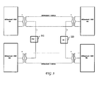
FIG. 3 illustrates a third example embodiment of low frequency noise prevention in a power over Ethernet system. -
FIG. 4 illustrates an equivalent circuit for a differential data pair. -
FIG. 5 illustrates a fourth example embodiment of low frequency noise prevention in a power over Ethernet system. -
FIG. 6 illustrates a second equivalent circuit for a differential data pair. - Various embodiments of the invention are discussed in detail below. While specific implementations are discussed, it should be understood that this is done for illustration purposes only. A person skilled in the relevant art will recognize that other components and configurations may be used without parting from the spirit and scope of the invention.
- Power over Ethernet (PoE) can be used to deliver power over wire pairs that are used for data transmission. PoE can be applied to various contexts and can be used alongside data transmission standards such as 1000BASE-T, 10GBASE-T, 40GBASE-T or higher data-rate transmission systems. The data transformers used in 1000BASE-T and 10GBASE-T systems can typically have much smaller inductance, and hence lower impedance, as compared to the data transformers used with 10BASE-T and 100BASE-TX systems. In preventing the 1000BASE-T or 10GBASE-T data transmission signal from being impacted by low frequency noise interference from the PoE subsystem (e.g., noise produced by the switching regulator on PoE devices), a high-impedance device is introduced on the center pin of the data transformer to isolate the low-frequency noise produced by the PoE devices.
-
FIG. 1 illustrates an example embodiment of low frequency noise prevention in a PoE system. As illustrated, the PoE system includesPSE 110 that transmits power toPD 120 over two wire pairs. Power delivered byPSE 110 toPD 120 is provided through the application of a voltage across the center taps of data transformer T1 that is coupled to a transmit (TX) wire pair and data transformer T3 that is coupled to a receive (RX) wire pair carried within an Ethernet cable. On the other end of the network link, power is received byPD 120 through the center taps of data transformer T2 and data transformer T4. - In general,
PD 120 can include a PoE module (not shown) that contains the electronics that would enablePD 120 to communicate withPSE 110 in accordance with IEEE 802.3af, 802.3at, legacy PoE transmission, or any other type of PoE transmission.PD 120 also includes a controller (e.g., pulse width modulation DC:DC controller) that controls a power transistor (e.g., field effect transistor (FET)), which in turn provides constant power to a load. - As noted, one of the issues of applying PoE to data transmission systems such as 1000BASE-T or 10GBASE-T is the impact produced by low-frequency noise interference from the PoE subsystem. For example, consider a 10BASE-T system that is operating over a 100 meter Ethernet cable. Such a system is particularly sensitive to low-frequency noise produced by the PD, such that the transmission of power over multiple wire pairs used in the 10G network link can preclude successful transmission of data at 10G rates.
- In the example embodiment illustrated in
FIG. 1 , additional high-impedance inductive elements (e.g., inductors) are used to isolate or attenuate the low-frequency noise that is generated by the PoE devices. Specifically, the high-voltage rail ofPSE 110 is injected onto center pins of data transformers T1 and T3 through series high-impedance inductive devices represented by inductors L1 and L2, andPD 120 receives the high DC voltage from the center pins of data transformers T2 and T4 through series high-impedance inductive devices represented by inductors L3 and L4. In operation, the high-impedance inductive devices represented by inductors L1-L4 are configured to isolate the low-frequency noise produced by the PSE and PD devices. - The example embodiment illustrated in
FIG. 1 is designed to isolate or attenuate the low-frequency noise from PoE devices on both ends of the link. In other embodiments, one of the PoE devices can be a relatively clean device that does not generate sufficient low-frequency noise that can interfere with the high-data rate transmission signals. In a typical installation, for example, the PD is more likely to create low-frequency noise that can interfere with the high-data rate transmission signals. Where a PoE device is a relatively clean device that does not generate significant low-frequency noise, the PoE device can be coupled to the center taps of the data transformers with little or no series high-impedance inductive devices. -
FIG. 2 illustrates a second example embodiment of low frequency noise prevention in a power over Ethernet system. As illustrated, high-impedance devices can be included on one end of the network link. Specifically,PD 220 receives the high DC voltage from the center pins of data transformers T2 and T4 through series high-impedance inductive devices represented by inductors L3 and L4. In this example, no high-impedance inductive devices are added to the PSE side of the PoE system. As would be appreciated, where the PD is a relatively clean device that does not generate sufficient low-frequency noise that can interfere with the high-data rate transmission signals, high-impedance inductive devices can be added to the PSE side and not to the PD side. -
FIG. 3 illustrates a third example embodiment of low frequency noise prevention in a power over Ethernet system. As illustrated, high-impedance inductive devices can be included on one side of the PoE devices. In this example, the high-voltage rail ofPSE 310 is injected onto the center pin ofdata transformers T 1 through the series high-impedance inductive device represented by inductor L1, andPD 320 receives the high DC voltage from the center pin of data transformers T2 through the series high-impedance inductive device represented by inductor L3. In operation, the high-impedance inductive devices represented by inductors L1 and L3 are configured to isolate the low-frequency noise produced by the PoE devices. As would be appreciated, other combinations of adding high-impedance inductive devices to one side of the PoE devices can be used without departing from the scope of the present invention. - As has been described, one example of a series high-impedance inductive device is a series inductor.
FIG. 4 illustrates an equivalent circuit for a differential data pair in the example of a series inductor. As illustrated, current "Itx" flows through both the data cable wires and current "Ins" flows into the center pin of the data transformer and returns through the ground path(s). According to the formula of impedance for the inductor (XL = jωL, ω = 2πf), the impedance XL will increase when the value of the inductor increases. Thus, when the value of inductor L is high enough, it will provide proper attenuation for low-frequency noise of the PoE device ("Ins"). - In the present invention, it is recognized that the particular form of the high-impedance device that is used to prevent low-frequency noise interference is implementation dependant. In another example, the high-impedance device can be implemented as a common mode choke.
-
FIG. 5 illustrates a fourth example embodiment of low frequency noise prevention in a power over Ethernet system where the series high-impedance inductive device is embodied as a common mode choke. In the example embodiment illustrated inFIG. 5 , common mode chokes L1, L2, L3 and L4 are used to isolate or attenuate the low-frequency noise from the PoE devices. Specifically, the high-voltage rail ofPSE 510 is injected onto center pins of data transformers T1 and T3 through common mode chokes L1 and L2, andPD 520 receives the high DC voltage from the center pins of data transformers T2 and T4 through common mode chokes L3 and L4. In operation, the common mode chokes L1-L4 are configured to isolate the low-frequency noise produced by the PoE devices. As would be appreciated, the common mode chokes need not be serially connected to the center taps of every data transformer T1-T4, but can be selectively placed depending on the origin of the low-frequency noise generated by the PoE system. -
FIG. 6 illustrates a second equivalent circuit for a differential data pair in the example of common mode chokes. Here, the low-frequency noise is treated as a common mode noise (Noise 1 and Noise 2) applied to the differential data pair. Current "Itx" flows through both the data cable wires and currents "Ins1" and "Ins2" each flow through one data cable wire and return through the ground path(s). Observe that current "Itx" flows through both windings but in opposing winding directions, while currents "Ins1" and Ins2" each flow through only one winding and in the same winding direction. The ground path(s) does not flow through a winding. - The inductance of Winding A restricts (reduces) the flow of current "Ins1" (when compared to
FIG. 4 ), thereby reducing the noise voltage across "Diff. Data - RX". Similarly the inductance of winding B restricts (hence reduces) the flow of current "Ins2". Windings A and B have the same number of turns. The ampere-turns created by Current "Itx" (but excluding any "Ins1" current component) flowing through winding A is cancelled by the opposing ampere-turns created by current "Itx" flowing through winding B. Ideally, the cancellation results in zero inductance and no restriction (no reduction) of current "Itx". "Itx" produces the same voltage across load "Diff. Data - RX". - As has been described, the prevention of a data transmission signal from being impacted by low frequency noise interference from the PoE subsystem can be enabled through the addition of high-impedance devices on the center pin of the data transformers. The addition of high-impedance devices on the center pins of the data transformers can be applied to any data transmission system that can be impacted by the low-frequency noise produced by the PoE devices.
- These and other aspects of the present invention will become apparent to those skilled in the art by a review of the preceding detailed description. Although a number of salient features of the present invention have been described above, the invention is capable of other embodiments and of being practiced and carried out in various ways that would be apparent to one of ordinary skill in the art after reading the disclosed invention, therefore the above description should not be considered to be exclusive of these other embodiments. Also, it is to be understood that the phraseology and terminology employed herein are for the purposes of description and should not be regarded as limiting.
Claims (15)
- A power over Ethernet device, comprising:a first data transformer that is coupled to a first wire pair in a network cable;a second data transformer that is coupled to a second wire pair in a network cable; anda power over Ethernet module that is coupled to a center tap of said first data transformer and a center tap of said second data transformer, said power over Ethernet module being coupled to said center tap of said first data transformer via an inductive element.
- The power over Ethernet device of claim 1, wherein said inductive element is an inductor.
- The power over Ethernet device of claim 1, wherein said inductive element is a common mode choke.
- The power over Ethernet device of claim 1, wherein said power over Ethernet module is coupled to said center tap of said second data transformer via a second inductive element.
- The power over Ethernet device of claim 1, wherein said power over Ethernet module transmits power via said center tap of said first data transformer and said center tap of said second data transformer.
- The power over Ethernet device of claim 1, wherein said power over Ethernet module receives power via said center tap of said first data transformer and said center tap of said second data transformer.
- The power over Ethernet device of claim 1, wherein said first and second data transformers are used for 1000BASE-T transmission.
- The power over Ethernet device of claim 1, wherein said first and second data transformers are used for 10GBASE-T transmission.
- The power over Ethernet device of claim 1, wherein said first and second data transformers are used for 40GBASE-T transmission.
- A network powered device, comprising:a transmitter that is coupled to a first data transformer for data transmission by said transmitter, said first data transformer being coupled to a first copper twisted pair;a receiver that is coupled to a second data transformer for data reception by said receiver, said second data transformer being coupled to a second copper twisted pair; anda network powered module that receives power via said first and second copper twisted pair, said network powered module being coupled to a center tap of said first data transformer via a first inductive element and to a center tap of said second data transformer via a second inductive element.
- The network powered device of claim 10, wherein said first and second data transformers are used for 1000GBASE-T transmission.
- The network powered device of claim 10, wherein said first and second data transformers are used for 10GBASE-T transmission.
- The network powered device of claim 10, wherein said first and second data transformers are used for 40GBASE-T transmission.
- The network powered device of claim 10, wherein said first inductive element is an inductor.
- The network powered device of claim 10, wherein said first inductive element is a common mode choke element.
Applications Claiming Priority (2)
| Application Number | Priority Date | Filing Date | Title |
|---|---|---|---|
| US201261615968P | 2012-03-27 | 2012-03-27 | |
| US13/456,810 US20130262884A1 (en) | 2012-03-27 | 2012-04-26 | Low-Frequency Noise Interference Prevention in Power Over Ethernet Systems |
Publications (2)
| Publication Number | Publication Date |
|---|---|
| EP2645620A1 true EP2645620A1 (en) | 2013-10-02 |
| EP2645620B1 EP2645620B1 (en) | 2014-08-27 |
Family
ID=47074533
Family Applications (1)
| Application Number | Title | Priority Date | Filing Date |
|---|---|---|---|
| EP12006187.4A Active EP2645620B1 (en) | 2012-03-27 | 2012-08-31 | Low-frequency noise interference prevention in power over ethernet systems |
Country Status (5)
| Country | Link |
|---|---|
| US (1) | US20130262884A1 (en) |
| EP (1) | EP2645620B1 (en) |
| KR (1) | KR101393292B1 (en) |
| CN (2) | CN202872796U (en) |
| TW (1) | TW201340640A (en) |
Families Citing this family (11)
| Publication number | Priority date | Publication date | Assignee | Title |
|---|---|---|---|---|
| US20130262884A1 (en) * | 2012-03-27 | 2013-10-03 | Broadcom Corporation | Low-Frequency Noise Interference Prevention in Power Over Ethernet Systems |
| US9780974B2 (en) * | 2014-04-09 | 2017-10-03 | Linear Technology Corporation | Broadband power coupling/decoupling network for PoDL |
| US10148447B1 (en) * | 2015-09-29 | 2018-12-04 | Apple Inc. | Provision of power over a data interface using a separate return path |
| CN105897212A (en) * | 2015-12-08 | 2016-08-24 | 乐视致新电子科技(天津)有限公司 | Electromagnetic interference suppression method and device |
| TWI611671B (en) * | 2016-02-05 | 2018-01-11 | 韌硬軟機電股份有限公司 | System for transmitting control signals over twisted pair cabling using common mode of transformer |
| CN105703618B (en) * | 2016-03-05 | 2019-06-25 | 上海斐讯数据通信技术有限公司 | A kind of circuit and implementation method for realizing high-power power supply using routine POE |
| US11070249B2 (en) | 2017-09-28 | 2021-07-20 | British Telecommunications Public Limited Company | Controlling communications in respect of local area networks |
| CN111201718B (en) * | 2017-10-10 | 2021-10-01 | 英国电讯有限公司 | Identifying interfering links in a local area network |
| US11290291B2 (en) * | 2018-07-31 | 2022-03-29 | Analog Devices International Unlimited Company | Power over data lines system with combined dc coupling and common mode termination circuitry |
| US11418369B2 (en) * | 2019-08-01 | 2022-08-16 | Analog Devices International Unlimited Company | Minimizing DC bias voltage difference across AC-blocking capacitors in PoDL system |
| US11631523B2 (en) | 2020-11-20 | 2023-04-18 | Analog Devices International Unlimited Company | Symmetric split planar transformer |
Citations (3)
| Publication number | Priority date | Publication date | Assignee | Title |
|---|---|---|---|---|
| WO2000064099A2 (en) * | 1999-04-16 | 2000-10-26 | Invensys Systems, Inc. | Powered ethernet for instrumentation and control |
| US6140911A (en) * | 1997-05-29 | 2000-10-31 | 3Com Corporation | Power transfer apparatus for concurrently transmitting data and power over data wires |
| US20080062590A1 (en) * | 2006-09-06 | 2008-03-13 | Cisco Technology, Inc. | Powered communications interface with DC current imbalance compensation |
Family Cites Families (6)
| Publication number | Priority date | Publication date | Assignee | Title |
|---|---|---|---|---|
| JP2005151796A (en) * | 2003-09-30 | 2005-06-09 | Sony Corp | Switching power supply circuit |
| US8132027B2 (en) * | 2005-06-16 | 2012-03-06 | Agere Systems Inc. | Transformerless power over ethernet system |
| GB0608456D0 (en) * | 2006-04-28 | 2006-06-07 | Tyco Electronics Amp Espana | An assembly for permitting power-over-ethernet connection |
| US8037324B2 (en) * | 2007-03-20 | 2011-10-11 | Broadcom Corporation | Power over ethernet connector with integrated power source equipment (PSE) controller supporting high power applications |
| CN101282275B (en) * | 2008-05-23 | 2013-01-30 | 杭州华三通信技术有限公司 | Telecommunication Ethernet system and repeater |
| US20130262884A1 (en) * | 2012-03-27 | 2013-10-03 | Broadcom Corporation | Low-Frequency Noise Interference Prevention in Power Over Ethernet Systems |
-
2012
- 2012-04-26 US US13/456,810 patent/US20130262884A1/en not_active Abandoned
- 2012-08-31 EP EP12006187.4A patent/EP2645620B1/en active Active
- 2012-09-14 TW TW101133677A patent/TW201340640A/en unknown
- 2012-09-19 KR KR1020120103659A patent/KR101393292B1/en active IP Right Grant
- 2012-09-27 CN CN2012204988007U patent/CN202872796U/en not_active Expired - Fee Related
- 2012-09-27 CN CN2012103659825A patent/CN103368661A/en active Pending
Patent Citations (3)
| Publication number | Priority date | Publication date | Assignee | Title |
|---|---|---|---|---|
| US6140911A (en) * | 1997-05-29 | 2000-10-31 | 3Com Corporation | Power transfer apparatus for concurrently transmitting data and power over data wires |
| WO2000064099A2 (en) * | 1999-04-16 | 2000-10-26 | Invensys Systems, Inc. | Powered ethernet for instrumentation and control |
| US20080062590A1 (en) * | 2006-09-06 | 2008-03-13 | Cisco Technology, Inc. | Powered communications interface with DC current imbalance compensation |
Also Published As
| Publication number | Publication date |
|---|---|
| TW201340640A (en) | 2013-10-01 |
| KR20130109916A (en) | 2013-10-08 |
| KR101393292B1 (en) | 2014-05-12 |
| EP2645620B1 (en) | 2014-08-27 |
| CN202872796U (en) | 2013-04-10 |
| US20130262884A1 (en) | 2013-10-03 |
| CN103368661A (en) | 2013-10-23 |
Similar Documents
| Publication | Publication Date | Title |
|---|---|---|
| EP2645620B1 (en) | Low-frequency noise interference prevention in power over ethernet systems | |
| US8987933B2 (en) | Power over one-pair Ethernet approach | |
| US8044747B2 (en) | Capacitor coupled Ethernet | |
| EP3195419B1 (en) | Power over ethernet for 10gbase-t ethernet | |
| US7964993B2 (en) | Network devices with solid state transformer and class AB output stage for active EMI suppression and termination of open-drain transmit drivers of a physical device | |
| US20190190322A1 (en) | System and method for improved dc power line communication | |
| JP2020518151A (en) | Adaptive common mode dimmer | |
| US10148447B1 (en) | Provision of power over a data interface using a separate return path | |
| TWI481212B (en) | Power over ethernet for bi-directional ethernet over single pair | |
| US20080136256A1 (en) | Network devices with solid state transformer and electronic load circuit to provide termination of open-drain transmit drivers of a physical layer module | |
| JP2006526955A (en) | Splitter | |
| EP3503417B1 (en) | Transceiver and system for electromagnetic emission detection | |
| US8217529B2 (en) | System and method for enabling power applications over a single communication pair | |
| US9960810B1 (en) | Transmission of ethernet signals and power over coaxial cable | |
| US20190106066A1 (en) | System, method and apparatus for one-pair power over ethernet in an automotive application | |
| US7851938B2 (en) | Midspan powering without the use of data transformers in a power over Ethernet application | |
| Heller et al. | Power-over-Ethernet for avionic networks | |
| US20200145237A1 (en) | Simultaneous power injection in power over ethernet system | |
| US7975153B2 (en) | Transmission impedance for four-pair midspan powering in a power over ethernet application | |
| JP2006521031A (en) | Method and power supply apparatus for supplying power to a current sink (ED) via two data line pairs of a local area network (LAN) |
Legal Events
| Date | Code | Title | Description |
|---|---|---|---|
| PUAI | Public reference made under article 153(3) epc to a published international application that has entered the european phase |
Free format text: ORIGINAL CODE: 0009012 |
|
| 17P | Request for examination filed |
Effective date: 20120831 |
|
| AK | Designated contracting states |
Kind code of ref document: A1 Designated state(s): AL AT BE BG CH CY CZ DE DK EE ES FI FR GB GR HR HU IE IS IT LI LT LU LV MC MK MT NL NO PL PT RO RS SE SI SK SM TR |
|
| AX | Request for extension of the european patent |
Extension state: BA ME |
|
| GRAP | Despatch of communication of intention to grant a patent |
Free format text: ORIGINAL CODE: EPIDOSNIGR1 |
|
| INTG | Intention to grant announced |
Effective date: 20140321 |
|
| RBV | Designated contracting states (corrected) |
Designated state(s): AL AT BE BG CH CY CZ DE DK EE ES FI FR GB GR HR HU IE IS IT LI LT LU LV MC MK MT NL NO PL PT RO RS SE SI SK SM TR |
|
| GRAS | Grant fee paid |
Free format text: ORIGINAL CODE: EPIDOSNIGR3 |
|
| GRAA | (expected) grant |
Free format text: ORIGINAL CODE: 0009210 |
|
| AK | Designated contracting states |
Kind code of ref document: B1 Designated state(s): AL AT BE BG CH CY CZ DE DK EE ES FI FR GB GR HR HU IE IS IT LI LT LU LV MC MK MT NL NO PL PT RO RS SE SI SK SM TR |
|
| REG | Reference to a national code |
Ref country code: GB Ref legal event code: FG4D |
|
| REG | Reference to a national code |
Ref country code: CH Ref legal event code: EP |
|
| REG | Reference to a national code |
Ref country code: DE Ref legal event code: R081 Ref document number: 602012002840 Country of ref document: DE Owner name: AVAGO TECHNOLOGIES GENERAL IP (SINGAPORE) PTE., SG Free format text: FORMER OWNER: BROADCOM CORPORATION, IRVINE, CALIF., US |
|
| REG | Reference to a national code |
Ref country code: AT Ref legal event code: REF Ref document number: 684958 Country of ref document: AT Kind code of ref document: T Effective date: 20140915 |
|
| REG | Reference to a national code |
Ref country code: IE Ref legal event code: FG4D |
|
| REG | Reference to a national code |
Ref country code: DE Ref legal event code: R096 Ref document number: 602012002840 Country of ref document: DE Effective date: 20141009 |
|
| REG | Reference to a national code |
Ref country code: AT Ref legal event code: MK05 Ref document number: 684958 Country of ref document: AT Kind code of ref document: T Effective date: 20140827 |
|
| REG | Reference to a national code |
Ref country code: LT Ref legal event code: MG4D |
|
| REG | Reference to a national code |
Ref country code: NL Ref legal event code: VDEP Effective date: 20140827 |
|
| PG25 | Lapsed in a contracting state [announced via postgrant information from national office to epo] |
Ref country code: GR Free format text: LAPSE BECAUSE OF FAILURE TO SUBMIT A TRANSLATION OF THE DESCRIPTION OR TO PAY THE FEE WITHIN THE PRESCRIBED TIME-LIMIT Effective date: 20141128 Ref country code: SE Free format text: LAPSE BECAUSE OF FAILURE TO SUBMIT A TRANSLATION OF THE DESCRIPTION OR TO PAY THE FEE WITHIN THE PRESCRIBED TIME-LIMIT Effective date: 20140827 Ref country code: FI Free format text: LAPSE BECAUSE OF FAILURE TO SUBMIT A TRANSLATION OF THE DESCRIPTION OR TO PAY THE FEE WITHIN THE PRESCRIBED TIME-LIMIT Effective date: 20140827 Ref country code: PT Free format text: LAPSE BECAUSE OF FAILURE TO SUBMIT A TRANSLATION OF THE DESCRIPTION OR TO PAY THE FEE WITHIN THE PRESCRIBED TIME-LIMIT Effective date: 20141229 Ref country code: NO Free format text: LAPSE BECAUSE OF FAILURE TO SUBMIT A TRANSLATION OF THE DESCRIPTION OR TO PAY THE FEE WITHIN THE PRESCRIBED TIME-LIMIT Effective date: 20141127 Ref country code: BG Free format text: LAPSE BECAUSE OF FAILURE TO SUBMIT A TRANSLATION OF THE DESCRIPTION OR TO PAY THE FEE WITHIN THE PRESCRIBED TIME-LIMIT Effective date: 20141127 Ref country code: LT Free format text: LAPSE BECAUSE OF FAILURE TO SUBMIT A TRANSLATION OF THE DESCRIPTION OR TO PAY THE FEE WITHIN THE PRESCRIBED TIME-LIMIT Effective date: 20140827 Ref country code: ES Free format text: LAPSE BECAUSE OF FAILURE TO SUBMIT A TRANSLATION OF THE DESCRIPTION OR TO PAY THE FEE WITHIN THE PRESCRIBED TIME-LIMIT Effective date: 20140827 |
|
| PG25 | Lapsed in a contracting state [announced via postgrant information from national office to epo] |
Ref country code: HR Free format text: LAPSE BECAUSE OF FAILURE TO SUBMIT A TRANSLATION OF THE DESCRIPTION OR TO PAY THE FEE WITHIN THE PRESCRIBED TIME-LIMIT Effective date: 20140827 Ref country code: IS Free format text: LAPSE BECAUSE OF FAILURE TO SUBMIT A TRANSLATION OF THE DESCRIPTION OR TO PAY THE FEE WITHIN THE PRESCRIBED TIME-LIMIT Effective date: 20141227 Ref country code: CY Free format text: LAPSE BECAUSE OF FAILURE TO SUBMIT A TRANSLATION OF THE DESCRIPTION OR TO PAY THE FEE WITHIN THE PRESCRIBED TIME-LIMIT Effective date: 20140827 Ref country code: AT Free format text: LAPSE BECAUSE OF FAILURE TO SUBMIT A TRANSLATION OF THE DESCRIPTION OR TO PAY THE FEE WITHIN THE PRESCRIBED TIME-LIMIT Effective date: 20140827 Ref country code: RS Free format text: LAPSE BECAUSE OF FAILURE TO SUBMIT A TRANSLATION OF THE DESCRIPTION OR TO PAY THE FEE WITHIN THE PRESCRIBED TIME-LIMIT Effective date: 20140827 Ref country code: LV Free format text: LAPSE BECAUSE OF FAILURE TO SUBMIT A TRANSLATION OF THE DESCRIPTION OR TO PAY THE FEE WITHIN THE PRESCRIBED TIME-LIMIT Effective date: 20140827 |
|
| PG25 | Lapsed in a contracting state [announced via postgrant information from national office to epo] |
Ref country code: NL Free format text: LAPSE BECAUSE OF FAILURE TO SUBMIT A TRANSLATION OF THE DESCRIPTION OR TO PAY THE FEE WITHIN THE PRESCRIBED TIME-LIMIT Effective date: 20140827 |
|
| PG25 | Lapsed in a contracting state [announced via postgrant information from national office to epo] |
Ref country code: CZ Free format text: LAPSE BECAUSE OF FAILURE TO SUBMIT A TRANSLATION OF THE DESCRIPTION OR TO PAY THE FEE WITHIN THE PRESCRIBED TIME-LIMIT Effective date: 20140827 Ref country code: BE Free format text: LAPSE BECAUSE OF NON-PAYMENT OF DUE FEES Effective date: 20140831 Ref country code: RO Free format text: LAPSE BECAUSE OF FAILURE TO SUBMIT A TRANSLATION OF THE DESCRIPTION OR TO PAY THE FEE WITHIN THE PRESCRIBED TIME-LIMIT Effective date: 20140827 Ref country code: DK Free format text: LAPSE BECAUSE OF FAILURE TO SUBMIT A TRANSLATION OF THE DESCRIPTION OR TO PAY THE FEE WITHIN THE PRESCRIBED TIME-LIMIT Effective date: 20140827 Ref country code: IT Free format text: LAPSE BECAUSE OF FAILURE TO SUBMIT A TRANSLATION OF THE DESCRIPTION OR TO PAY THE FEE WITHIN THE PRESCRIBED TIME-LIMIT Effective date: 20140827 Ref country code: SK Free format text: LAPSE BECAUSE OF FAILURE TO SUBMIT A TRANSLATION OF THE DESCRIPTION OR TO PAY THE FEE WITHIN THE PRESCRIBED TIME-LIMIT Effective date: 20140827 Ref country code: EE Free format text: LAPSE BECAUSE OF FAILURE TO SUBMIT A TRANSLATION OF THE DESCRIPTION OR TO PAY THE FEE WITHIN THE PRESCRIBED TIME-LIMIT Effective date: 20140827 |
|
| REG | Reference to a national code |
Ref country code: DE Ref legal event code: R097 Ref document number: 602012002840 Country of ref document: DE |
|
| PG25 | Lapsed in a contracting state [announced via postgrant information from national office to epo] |
Ref country code: PL Free format text: LAPSE BECAUSE OF FAILURE TO SUBMIT A TRANSLATION OF THE DESCRIPTION OR TO PAY THE FEE WITHIN THE PRESCRIBED TIME-LIMIT Effective date: 20140827 Ref country code: MC Free format text: LAPSE BECAUSE OF FAILURE TO SUBMIT A TRANSLATION OF THE DESCRIPTION OR TO PAY THE FEE WITHIN THE PRESCRIBED TIME-LIMIT Effective date: 20140827 |
|
| REG | Reference to a national code |
Ref country code: IE Ref legal event code: MM4A |
|
| PLBE | No opposition filed within time limit |
Free format text: ORIGINAL CODE: 0009261 |
|
| STAA | Information on the status of an ep patent application or granted ep patent |
Free format text: STATUS: NO OPPOSITION FILED WITHIN TIME LIMIT |
|
| 26N | No opposition filed |
Effective date: 20150528 |
|
| REG | Reference to a national code |
Ref country code: FR Ref legal event code: ST Effective date: 20150715 |
|
| PG25 | Lapsed in a contracting state [announced via postgrant information from national office to epo] |
Ref country code: IE Free format text: LAPSE BECAUSE OF NON-PAYMENT OF DUE FEES Effective date: 20140831 |
|
| PG25 | Lapsed in a contracting state [announced via postgrant information from national office to epo] |
Ref country code: FR Free format text: LAPSE BECAUSE OF NON-PAYMENT OF DUE FEES Effective date: 20141027 Ref country code: SI Free format text: LAPSE BECAUSE OF FAILURE TO SUBMIT A TRANSLATION OF THE DESCRIPTION OR TO PAY THE FEE WITHIN THE PRESCRIBED TIME-LIMIT Effective date: 20140827 |
|
| REG | Reference to a national code |
Ref country code: CH Ref legal event code: PL |
|
| PG25 | Lapsed in a contracting state [announced via postgrant information from national office to epo] |
Ref country code: CH Free format text: LAPSE BECAUSE OF NON-PAYMENT OF DUE FEES Effective date: 20150831 Ref country code: LI Free format text: LAPSE BECAUSE OF NON-PAYMENT OF DUE FEES Effective date: 20150831 |
|
| PG25 | Lapsed in a contracting state [announced via postgrant information from national office to epo] |
Ref country code: SM Free format text: LAPSE BECAUSE OF FAILURE TO SUBMIT A TRANSLATION OF THE DESCRIPTION OR TO PAY THE FEE WITHIN THE PRESCRIBED TIME-LIMIT Effective date: 20140827 |
|
| PG25 | Lapsed in a contracting state [announced via postgrant information from national office to epo] |
Ref country code: MT Free format text: LAPSE BECAUSE OF FAILURE TO SUBMIT A TRANSLATION OF THE DESCRIPTION OR TO PAY THE FEE WITHIN THE PRESCRIBED TIME-LIMIT Effective date: 20140827 |
|
| PG25 | Lapsed in a contracting state [announced via postgrant information from national office to epo] |
Ref country code: BE Free format text: LAPSE BECAUSE OF FAILURE TO SUBMIT A TRANSLATION OF THE DESCRIPTION OR TO PAY THE FEE WITHIN THE PRESCRIBED TIME-LIMIT Effective date: 20140827 Ref country code: HU Free format text: LAPSE BECAUSE OF FAILURE TO SUBMIT A TRANSLATION OF THE DESCRIPTION OR TO PAY THE FEE WITHIN THE PRESCRIBED TIME-LIMIT; INVALID AB INITIO Effective date: 20120831 Ref country code: LU Free format text: LAPSE BECAUSE OF NON-PAYMENT OF DUE FEES Effective date: 20140831 |
|
| REG | Reference to a national code |
Ref country code: DE Ref legal event code: R082 Ref document number: 602012002840 Country of ref document: DE Representative=s name: BOSCH JEHLE PATENTANWALTSGESELLSCHAFT MBH, DE Ref country code: DE Ref legal event code: R081 Ref document number: 602012002840 Country of ref document: DE Owner name: AVAGO TECHNOLOGIES INTERNATIONAL SALES PTE. LT, SG Free format text: FORMER OWNER: BROADCOM CORP., IRVINE, CALIF., US Ref country code: DE Ref legal event code: R081 Ref document number: 602012002840 Country of ref document: DE Owner name: AVAGO TECHNOLOGIES GENERAL IP (SINGAPORE) PTE., SG Free format text: FORMER OWNER: BROADCOM CORP., IRVINE, CALIF., US |
|
| GBPC | Gb: european patent ceased through non-payment of renewal fee |
Effective date: 20160831 |
|
| PG25 | Lapsed in a contracting state [announced via postgrant information from national office to epo] |
Ref country code: GB Free format text: LAPSE BECAUSE OF NON-PAYMENT OF DUE FEES Effective date: 20160831 |
|
| PG25 | Lapsed in a contracting state [announced via postgrant information from national office to epo] |
Ref country code: TR Free format text: LAPSE BECAUSE OF FAILURE TO SUBMIT A TRANSLATION OF THE DESCRIPTION OR TO PAY THE FEE WITHIN THE PRESCRIBED TIME-LIMIT Effective date: 20140827 |
|
| PG25 | Lapsed in a contracting state [announced via postgrant information from national office to epo] |
Ref country code: MK Free format text: LAPSE BECAUSE OF FAILURE TO SUBMIT A TRANSLATION OF THE DESCRIPTION OR TO PAY THE FEE WITHIN THE PRESCRIBED TIME-LIMIT Effective date: 20140827 |
|
| REG | Reference to a national code |
Ref country code: DE Ref legal event code: R082 Ref document number: 602012002840 Country of ref document: DE Representative=s name: BOSCH JEHLE PATENTANWALTSGESELLSCHAFT MBH, DE Ref country code: DE Ref legal event code: R081 Ref document number: 602012002840 Country of ref document: DE Owner name: AVAGO TECHNOLOGIES INTERNATIONAL SALES PTE. LT, SG Free format text: FORMER OWNER: AVAGO TECHNOLOGIES GENERAL IP (SINGAPORE) PTE. LTD., SINGAPORE, SG |
|
| PG25 | Lapsed in a contracting state [announced via postgrant information from national office to epo] |
Ref country code: AL Free format text: LAPSE BECAUSE OF FAILURE TO SUBMIT A TRANSLATION OF THE DESCRIPTION OR TO PAY THE FEE WITHIN THE PRESCRIBED TIME-LIMIT Effective date: 20140827 |
|
| PGFP | Annual fee paid to national office [announced via postgrant information from national office to epo] |
Ref country code: DE Payment date: 20230731 Year of fee payment: 12 |