EP2650220A2 - Deicer zones with shedding-enhanced borders - Google Patents
Deicer zones with shedding-enhanced borders Download PDFInfo
- Publication number
- EP2650220A2 EP2650220A2 EP20130163231 EP13163231A EP2650220A2 EP 2650220 A2 EP2650220 A2 EP 2650220A2 EP 20130163231 EP20130163231 EP 20130163231 EP 13163231 A EP13163231 A EP 13163231A EP 2650220 A2 EP2650220 A2 EP 2650220A2
- Authority
- EP
- European Patent Office
- Prior art keywords
- edge
- ice
- envelope
- protection system
- edge region
- Prior art date
- Legal status (The legal status is an assumption and is not a legal conclusion. Google has not performed a legal analysis and makes no representation as to the accuracy of the status listed.)
- Granted
Links
Images


Classifications
-
- B—PERFORMING OPERATIONS; TRANSPORTING
- B64—AIRCRAFT; AVIATION; COSMONAUTICS
- B64D—EQUIPMENT FOR FITTING IN OR TO AIRCRAFT; FLIGHT SUITS; PARACHUTES; ARRANGEMENTS OR MOUNTING OF POWER PLANTS OR PROPULSION TRANSMISSIONS IN AIRCRAFT
- B64D15/00—De-icing or preventing icing on exterior surfaces of aircraft
- B64D15/02—De-icing or preventing icing on exterior surfaces of aircraft by ducted hot gas or liquid
-
- B—PERFORMING OPERATIONS; TRANSPORTING
- B64—AIRCRAFT; AVIATION; COSMONAUTICS
- B64D—EQUIPMENT FOR FITTING IN OR TO AIRCRAFT; FLIGHT SUITS; PARACHUTES; ARRANGEMENTS OR MOUNTING OF POWER PLANTS OR PROPULSION TRANSMISSIONS IN AIRCRAFT
- B64D15/00—De-icing or preventing icing on exterior surfaces of aircraft
- B64D15/12—De-icing or preventing icing on exterior surfaces of aircraft by electric heating
- B64D15/14—De-icing or preventing icing on exterior surfaces of aircraft by electric heating controlled cyclically along length of surface
-
- H—ELECTRICITY
- H05—ELECTRIC TECHNIQUES NOT OTHERWISE PROVIDED FOR
- H05B—ELECTRIC HEATING; ELECTRIC LIGHT SOURCES NOT OTHERWISE PROVIDED FOR; CIRCUIT ARRANGEMENTS FOR ELECTRIC LIGHT SOURCES, IN GENERAL
- H05B1/00—Details of electric heating devices
- H05B1/02—Automatic switching arrangements specially adapted to apparatus ; Control of heating devices
- H05B1/0227—Applications
- H05B1/023—Industrial applications
- H05B1/0236—Industrial applications for vehicles
Definitions
- An aircraft will typically include an ice protection system to prevent excessive ice accumulation on its wings, stabilizers, engine inlet lips, and/or pylons.
- the ice protection system can incorporate an array of contiguous deicing zones associated with areas fore and/or aft of the leading edge. Each deicing zone can comprise an envelope corresponding to an ice-protection area on the aircraft.
- An ice protection system is provided wherein edge regions of adjacent deicing envelopes are configured to allow the ensuing airstream to enhance ice removal along spanwise interzone borders. Specifically, the relevant edge regions are provided with features which project and recess in a direction substantially parallel to the airstream direction. In this manner, ice accumulating along an interzone border is presented in vacillating pockets which can be easily broken by the airstream and swept away.
- an aircraft 10 can comprise fuselage 11, wings 12, horizontal stabilizers 13, a vertical stabilizer 14, engines 15, and pylons 16.
- the wings 12 are the aircraft's primary lift providers.
- the horizontal stabilizers 13 prevent up-down motion of the aircraft nose, and the vertical stabilizer 14 discourages side to side swinging.
- the engines 15 are the aircraft's thrust-providing means and the pylons 16 serve as underwing mounting means for the engines.
- each wing 12, stabilizer 13-14, engine 15, and/or pylon 16 can be viewed as having an ice-susceptible surface 20 with a leading edge 30.
- the airstream A first encounters the leading edge 30 and then travels in a fore-aft direction therefrom.
- the surface 20 is provided with an ice protection system 40 comprising an ice protection array 50 and a controller 60 operably connected to the array 50.
- the illustrated ice protection array 50 comprises a first set 100 of contiguous deicing zones 101-103, a second set 200 of contiguous deicing zones 201-203, and an anti-icing zone 301.
- the anti-icing zone 301 will usually coincide with the leading edge 30 and can be positioned between the fore zone 101 of the first deicer set 100 and the fore zone 201 of the second deicer set 200.
- the surface 20 appears flat in the drawing, this is simply for ease in illustration and explanation. In most instances, the surface 20 will have a curved profile wrapping around the leading edge 30 of the associated aircraft structure. If, for example, the ice-susceptible surface 20 is on a wing 12 or a horizontal stabilizer 13, the deicing zones 101-103 could be located on upper portion of the wing/stabilizer and the deicing zones 201-203 could be located on its lower portion. If the surface 20 resides on the vertical stabilizer 14 or one of the pylons 16, the deicing zones 101-103 could occupy its rightside portions and the deicing zones 201-203 could occupy its leftside portions. If the surface area 20 is on one of the engines 15, the deicing zones 101-103 could be situated on inner lip portions and the deicing zones 201-203 could be situated on outer lip portions.
- the deicing zones 101-103 in the first deicer set 100 each comprise an envelope 111-113 defining an ice protection area 121-123.
- Each envelope 111-113 includes an electrothermal heater layer 131-133 which converts electric power to heat to deice the corresponding ice-protection area 121-123.
- the envelopes 111-113 can comprise further layers (e.g., layers 141-143, layers 151-153, etc.) surrounding the heater layers 131-133 for thermal transfer, electrical insulation, and/or protection purposes.
- the envelopes 111-112 share a common interzone border 160 and the envelopes 112-113 share a common interzone border 170, which both extend generally in a direction perpendicular to the airstream direction A.
- the interzone border 160 is flanked by an end region 161 of the envelope 111 and an end region 162 of the envelope 112.
- the interzone border 170 is flanked by an end region 172 of the envelope 112 and an end region 173 of the envelope 113.
- the envelope 111 has a non-common (e.g., fore) border 180 adjacent its edge region 181 and the envelope 113 has a non-common (e.g., aft) border 190 adjacent its edge region 193.
- the border 180 and the border 190 also extend generally in a direction perpendicular to the airstream direction A.
- the deicing zones 201-203 in the second deicer set 200 include similar envelopes 211-213 defining ice protection areas 221-223 and including envelope layers (e.g., layers 231-233, layers 241-243, layers 251-253, etc.). They also include an interzone border 260 (flanked by envelope edge regions 261 and 262), an interzone border 270 (flanked by envelope edge regions 272 and 273), a fore border 280 (adjacent envelope edge region 281), and an aft border 290 (adjacent envelope edge region 293).
- the interzone border 260, the interzone border 270, the fore border 280, and the aft border 290 extend generally in a direction perpendicular to the airstream direction A.
- the anti-icing zone 301 can include an envelope 311 defining an ice protection area 321, housing an electrothermal heater layer 331, and including additional envelope layers 341 and 351.
- the anti-icing zone 301 can be bounded by borders 180 and 280 and flanked by envelope edge regions 181 and 281.
- FIG. 4-6 some possible power-supply procedures for the ice protection system 40 are shown.
- electrical power is episodically (not constantly) supplied to a heater for short time periods.
- the episode extent is selected so that enough heat is provided to loosen accumulated ice for sweeping away by the ensuing airstream.
- the episode-to-episode interlude is chosen so that an appropriate amount of ice accumulates therebetween.
- time durations will vary depending upon several factors, an episode will ordinarily last about five to ten seconds and will usually be less than twenty seconds. And the interlude between episodes is generally greater than ten seconds.
- the power-supply episodes are executed in a staggering schedule so as to minimize power-draw spikes.
- the heaters' episodes are collectively viewed in terms of time intervals t1-tn, with different heaters being supplied power during different intervals.
- a cycle is completed when a power-supply episode has occurred for each deicing zone.
- each cycle includes six intervals t1-t6, with power being supplied to sequentially to zones 101-103 and then sequentially to zones 201-203.
- each cycle includes three intervals t1-t3, with power being supplied sequentially to zones 101-103 and sequentially to zones 201-203 at the same time.
- each cycle includes eight intervals t1-t8, with only one deicing zone being supplied power during some of the intervals (e.g., intervals t1, t4, t5, t8) and two deicing zones being supplied with power during other intervals (e.g., intervals t2, t3, t6, t7).
- the anti-icing zone 301 is continuously supplied with power in all of the illustrated power-supply procedures. This continuous supply of electrical power is intended to persistently heat the corresponding ice protection area 311 so that ice never even forms thereon.
- the use of such an anti-icing approach along a leading edge is considered customary in airfoil ice protection.
- the envelope structures commonly include further layers (e.g., layers 141-143, layers 151-153, etc.) surrounding the heater layers 131-133, at least some of which are for electrical insulation and/or protection purposes.
- envelope constructions can often hinder the transfer of ice-melting heat to edge regions of the deicing zones. This hindering is especially apparent when two adjacent deicer envelopes share a spanwise interzone border (e.g., envelopes 111-112 sharing border 160, adjacent envelopes 112-113 sharing border 170, adjacent envelopes 211-212 sharing border 260, and adjacent envelopes 212-213 sharing border 270).
- the non-heating layers are generally optimized to provide adequate electrical insulation, sufficient environmental protection, maximum heat transfer, lighter weights, lower power draws, and longer lives. As such, trimming thicknesses along edge regions could compromise electrical insulation and environmental protection. Likewise, padding thicknesses along non-edge regions to equalize heat transfer parameters could cause weight and power-draw concessions.
- the ice protection system 40 addresses border-heat-hindrance issues by configuring envelope edge regions to enhance deicing in these interzone vicinities.
- the interzone edge regions i.e., edge regions 161-162, edge regions 172-173, edge regions 261-262
- the contour of interzone edge regions are provided with complementary and/or undulating edge features (i.e., features 166-167, features 176-177, features 266-267, features 276-277) which puzzle-piece together to form a continuous interzone border.
- This type of perimeter profile facilitates ice removal because the edge features project-and-recess in a direction substantially parallel to the airstream direction A.
- ice accumulating along spanwise interzone borders follows the linear path of the envelope regions and often forms a blunt unbroken ice cordon.
- any ice accumulating along an interzone border will follow the nonlinear perimeter of the too-cold edge region. Instead of a solid cordon, the ice will be presented in pockets vacillating across the aircraft surface. To the extent that there is bonding among the ice pockets, it can be easily broken by the airstream A and swept away.
- the edge features 166-167, the edge features 176-177, the edge features 266-267, and/or the edge features 276-277 can have round, triangular, rectangular, polygonal, or any other suitable shape.
- the edge features of each interzone border within a set can be aligned with or they can be offset from one another (see and compare, e.g., the A figures and the B figures in the each drawing series).
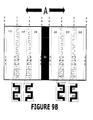
- the features can vary in frequency or amplitude along each interzone border (see, e.g., the C-D figures each drawing series). Or they can vary in frequency or amplitude from one interzone border to another (see, e.g., E-F figures each drawing series).
- the aircraft 10, the surface 20, the system 40, the array 50, the controller 60, the deicer set 100, the deicing zones 101-103 (and their layers, edge regions, and interzone borders), the deicer set 200, the deicing zone 201-203 (and their layers, edge regions, and interzone borders) and/or the anti-icing zone 301 have been shown and described with respect to a certain embodiments, it is obvious that equivalent alterations and modifications will occur to others skilled in the art upon the reading and understanding of this specification and the annexed drawings. Specifically, for example, ice protection systems with more or less deicing and/or anti-icing zones are feasible and foreseeable. And while a particular feature of the aircraft 10 or the ice protection system 40 may have been described above with respect to some of the illustrated embodiments, such feature may be combined with one or more other features of the other embodiments, as may be desired and advantageous.
Abstract
Description
- An aircraft will typically include an ice protection system to prevent excessive ice accumulation on its wings, stabilizers, engine inlet lips, and/or pylons. The ice protection system can incorporate an array of contiguous deicing zones associated with areas fore and/or aft of the leading edge. Each deicing zone can comprise an envelope corresponding to an ice-protection area on the aircraft.
- An ice protection system is provided wherein edge regions of adjacent deicing envelopes are configured to allow the ensuing airstream to enhance ice removal along spanwise interzone borders. Specifically, the relevant edge regions are provided with features which project and recess in a direction substantially parallel to the airstream direction. In this manner, ice accumulating along an interzone border is presented in vacillating pockets which can be easily broken by the airstream and swept away.
-
-
Figure 1 shows an aircraft having several surfaces protectable by the ice protection system. -
Figures 2-3 shows flattened views of the ice protection system -
Figures 4-6 show standard power-supply procedures for the deicing zones of the ice protection system. -
Figures 7A-7F ,8A-8F ,9A-9F , and10A-10F show some possible nonlinear profiles for edge regions of deicing envelopes. - Referring to
Figure 1 , anaircraft 10 can comprisefuselage 11,wings 12,horizontal stabilizers 13, avertical stabilizer 14,engines 15, andpylons 16. Thewings 12 are the aircraft's primary lift providers. Thehorizontal stabilizers 13 prevent up-down motion of the aircraft nose, and thevertical stabilizer 14 discourages side to side swinging. Theengines 15 are the aircraft's thrust-providing means and thepylons 16 serve as underwing mounting means for the engines. - Referring to
Figures 2-3 , eachwing 12, stabilizer 13-14,engine 15, and/orpylon 16 can be viewed as having an ice-susceptible surface 20 with a leading edge 30. The airstream A first encounters the leading edge 30 and then travels in a fore-aft direction therefrom. - The
surface 20 is provided with anice protection system 40 comprising anice protection array 50 and acontroller 60 operably connected to thearray 50. The illustratedice protection array 50 comprises afirst set 100 of contiguous deicing zones 101-103, asecond set 200 of contiguous deicing zones 201-203, and ananti-icing zone 301. Theanti-icing zone 301 will usually coincide with the leading edge 30 and can be positioned between thefore zone 101 of the first deicer set 100 and thefore zone 201 of the second deicer set 200. - While the
surface 20 appears flat in the drawing, this is simply for ease in illustration and explanation. In most instances, thesurface 20 will have a curved profile wrapping around the leading edge 30 of the associated aircraft structure. If, for example, the ice-susceptible surface 20 is on awing 12 or ahorizontal stabilizer 13, the deicing zones 101-103 could be located on upper portion of the wing/stabilizer and the deicing zones 201-203 could be located on its lower portion. If thesurface 20 resides on thevertical stabilizer 14 or one of thepylons 16, the deicing zones 101-103 could occupy its rightside portions and the deicing zones 201-203 could occupy its leftside portions. If thesurface area 20 is on one of theengines 15, the deicing zones 101-103 could be situated on inner lip portions and the deicing zones 201-203 could be situated on outer lip portions. - The deicing zones 101-103 in the first deicer set 100 each comprise an envelope 111-113 defining an ice protection area 121-123. Each envelope 111-113 includes an electrothermal heater layer 131-133 which converts electric power to heat to deice the corresponding ice-protection area 121-123. The envelopes 111-113 can comprise further layers (e.g., layers 141-143, layers 151-153, etc.) surrounding the heater layers 131-133 for thermal transfer, electrical insulation, and/or protection purposes.
- The envelopes 111-112 share a
common interzone border 160 and the envelopes 112-113 share acommon interzone border 170, which both extend generally in a direction perpendicular to the airstream direction A. Theinterzone border 160 is flanked by anend region 161 of theenvelope 111 and anend region 162 of theenvelope 112. Theinterzone border 170 is flanked by anend region 172 of theenvelope 112 and anend region 173 of theenvelope 113. - The
envelope 111 has a non-common (e.g., fore)border 180 adjacent itsedge region 181 and theenvelope 113 has a non-common (e.g., aft)border 190 adjacent itsedge region 193. Theborder 180 and theborder 190 also extend generally in a direction perpendicular to the airstream direction A. - The deicing zones 201-203 in the
second deicer set 200 include similar envelopes 211-213 defining ice protection areas 221-223 and including envelope layers (e.g., layers 231-233, layers 241-243, layers 251-253, etc.). They also include an interzone border 260 (flanked byenvelope edge regions 261 and 262), an interzone border 270 (flanked byenvelope edge regions 272 and 273), a fore border 280 (adjacent envelope edge region 281), and an aft border 290 (adjacent envelope edge region 293). Theinterzone border 260, theinterzone border 270, thefore border 280, and theaft border 290 extend generally in a direction perpendicular to the airstream direction A. - The
anti-icing zone 301 can include anenvelope 311 defining anice protection area 321, housing anelectrothermal heater layer 331, and includingadditional envelope layers 341 and 351. Theanti-icing zone 301 can be bounded byborders envelope edge regions - Referring to
Figures 4-6 , some possible power-supply procedures for theice protection system 40 are shown. In each of these procedures, electrical power is episodically (not constantly) supplied to a heater for short time periods. The episode extent is selected so that enough heat is provided to loosen accumulated ice for sweeping away by the ensuing airstream. The episode-to-episode interlude is chosen so that an appropriate amount of ice accumulates therebetween. Although these time durations will vary depending upon several factors, an episode will ordinarily last about five to ten seconds and will usually be less than twenty seconds. And the interlude between episodes is generally greater than ten seconds. - In a zoned electrothermal deicing procedure, the power-supply episodes are executed in a staggering schedule so as to minimize power-draw spikes. The heaters' episodes are collectively viewed in terms of time intervals t1-tn, with different heaters being supplied power during different intervals. A cycle is completed when a power-supply episode has occurred for each deicing zone.
- In
Figure 4 , each cycle includes six intervals t1-t6, with power being supplied to sequentially to zones 101-103 and then sequentially to zones 201-203. InFigure 5 , each cycle includes three intervals t1-t3, with power being supplied sequentially to zones 101-103 and sequentially to zones 201-203 at the same time. InFigure 6 , each cycle includes eight intervals t1-t8, with only one deicing zone being supplied power during some of the intervals (e.g., intervals t1, t4, t5, t8) and two deicing zones being supplied with power during other intervals (e.g., intervals t2, t3, t6, t7). - The
anti-icing zone 301 is continuously supplied with power in all of the illustrated power-supply procedures. This continuous supply of electrical power is intended to persistently heat the correspondingice protection area 311 so that ice never even forms thereon. The use of such an anti-icing approach along a leading edge is considered customary in airfoil ice protection. - As was indicated above, the envelope structures commonly include further layers (e.g., layers 141-143, layers 151-153, etc.) surrounding the heater layers 131-133, at least some of which are for electrical insulation and/or protection purposes. As such, envelope constructions can often hinder the transfer of ice-melting heat to edge regions of the deicing zones. This hindering is especially apparent when two adjacent deicer envelopes share a spanwise interzone border (e.g., envelopes 111-112 sharing
border 160, adjacent envelopes 112-113 sharingborder 170, adjacent envelopes 211-212 sharingborder 260, and adjacent envelopes 212-213 sharing border 270). - When designing a deicer envelope, the non-heating layers are generally optimized to provide adequate electrical insulation, sufficient environmental protection, maximum heat transfer, lighter weights, lower power draws, and longer lives. As such, trimming thicknesses along edge regions could compromise electrical insulation and environmental protection. Likewise, padding thicknesses along non-edge regions to equalize heat transfer parameters could cause weight and power-draw concessions.
- The
ice protection system 40 addresses border-heat-hindrance issues by configuring envelope edge regions to enhance deicing in these interzone vicinities. - As shown in the 7th through 10th series of drawings, the interzone edge regions (i.e., edge regions 161-162, edge regions 172-173, edge regions 261-262) have non-linear contours. More specifically, the contour of interzone edge regions are provided with complementary and/or undulating edge features (i.e., features 166-167, features 176-177, features 266-267, features 276-277) which puzzle-piece together to form a continuous interzone border.
- This type of perimeter profile facilitates ice removal because the edge features project-and-recess in a direction substantially parallel to the airstream direction A. With traditional deicers, ice accumulating along spanwise interzone borders follows the linear path of the envelope regions and often forms a blunt unbroken ice cordon. With the
ice protection system 40, any ice accumulating along an interzone border will follow the nonlinear perimeter of the too-cold edge region. Instead of a solid cordon, the ice will be presented in pockets vacillating across the aircraft surface. To the extent that there is bonding among the ice pockets, it can be easily broken by the airstream A and swept away. - As is shown in the 7th through 10th series of drawings, the edge features 166-167, the edge features 176-177, the edge features 266-267, and/or the edge features 276-277 can have round, triangular, rectangular, polygonal, or any other suitable shape. The edge features of each interzone border within a set can be aligned with or they can be offset from one another (see and compare, e.g., the A figures and the B figures in the each drawing series). The features can vary in frequency or amplitude along each interzone border (see, e.g., the C-D figures each drawing series). Or they can vary in frequency or amplitude from one interzone border to another (see, e.g., E-F figures each drawing series).
- Although the
aircraft 10, thesurface 20, thesystem 40, thearray 50, thecontroller 60, the deicer set 100, the deicing zones 101-103 (and their layers, edge regions, and interzone borders), the deicer set 200, the deicing zone 201-203 (and their layers, edge regions, and interzone borders) and/or theanti-icing zone 301 have been shown and described with respect to a certain embodiments, it is obvious that equivalent alterations and modifications will occur to others skilled in the art upon the reading and understanding of this specification and the annexed drawings. Specifically, for example, ice protection systems with more or less deicing and/or anti-icing zones are feasible and foreseeable. And while a particular feature of theaircraft 10 or theice protection system 40 may have been described above with respect to some of the illustrated embodiments, such feature may be combined with one or more other features of the other embodiments, as may be desired and advantageous. -
10 aircraft 11 fuselage 20 ice susceptible surface 12 wings 30 leading edge 13 horizontal stabilizers 40 ice protection system 14 vertical stabilizer 50 ice protection array 15 engines 60 controller 16 pylons 100 first set of deicing zones 200 second set of deicing zones 101 fore deicing zone 201 fore deicing zone 102 mid deicing zone 202 mid deicing zone 103 aft deicing zone 203 aft deicing zone 111 fore deicer envelope 211 fore deicer envelope 112 mid deicer envelope 212 mid deicer envelope 113 aft deicer envelope 213 aft deicer envelope 121 fore ice protection area 221 fore ice protection area 122 mid ice protection area 222 mid ice protection area 123 aft ice protection area 223 aft ice protection area 131 fore heating layer 231 fore heating layer 132 mid heating layer 232 mid heating layer 133 aft heating layer 233 aft heating layer 141 fore envelope layer 241 fore envelope layer 142 mid envelope layer 242 mid envelope layer 143 aft envelope layer 243 aft envelope layer 151 fore envelope layer 251 fore envelope layer 152 mid envelope layer 252 mid envelope layer 153 aft envelope layer 253 aft envelope layer 160 fore-mid border 260 fore-mid border 161 aft edge region of fore zone 261 aft edge region of fore zone 162 fore edge region of mid zone 262 fore edge region of mid zone 166 edge features 266 edge features 167 edge features 267 edge features 170 mid-aft border 270 mid-aft border 172 aft edge region of mid zone 272 aft edge region of mid zone 173 fore edge region of aft zone 273 fire edge region of aft zone 176 edge features 276 edge features 177 edge features 277 edge features 180 fore border 280 fore border 181 fore edge region of fore zone 281 fore edge region of fore zone 190 aft border 290 aft border 193 aft edge region of aft zone 291 aft edge region of aft zone 301 anti-icing zone 331 heating layer 311 envelope 341 envelope layer 321 ice protection area 351 envelope layer
Claims (15)
- An ice protection system (40) comprising a first set (100) of contiguous deicing zones (101-103); wherein:each deicing zone (101-103) comprises an envelope (111-113) defining an ice-protection area (121-123);each envelope (111-113) includes an electrothermal heater layer (131-133) which converts electric power to heat to deice the corresponding ice-protection area (101-103);at least two of the envelopes (111-112, 112-113) are adjacent and share a common interzone border (160,170);each of the adjacent envelopes (111-112, 112-113) includes an edge region (161-162, 172-173) flanking the interzone border (16,170); andthe edge regions (161-162, 172-173) of the adjacent envelopes are configured to enhance deicing at the interzone border by having nonlinear contours with edge features (166,167,176,177) which project-and-recess in a direction substantially parallel to the airstream direction.
- An ice protection system as set forth in claim 1, wherein the adjacent envelopes comprise a fore envelope (111) having an edge region (161) flanking the interzone border (160), this edge region (161) having nonlinear contours with edge features (166) which project-and-recess in a direction substantially parallel to the airstream direction; and/or
wherein the adjacent envelopes comprise an aft envelope (113) having an edge region (173) flanking the interzone border (170), this edge region (173) having nonlinear contours with edge features (177) which project-and-recess in a direction substantially parallel to the airstream direction; and/or
wherein the adjacent envelopes comprise a mid envelope (112) having a fore edge region (162) flanking the interzone border (160), this edge region (162) having nonlinear contours with edge features (167) which project-and-recess in a direction substantially parallel to the airstream direction; and/or
wherein the adjacent envelopes comprise a mid envelope (112) having an aft edge region (172) flanking the interzone border (170), this edge region (172) having nonlinear contours with edge features (176) which project-and-recess in a direction substantially parallel to the airstream direction. - An ice protection system as set forth in claim 1 or 2, comprising an anti-icing zone (301) positioned fore of the first set of the deicing zones (101-103).
- An ice protection system as set forth in any preceding claim, comprising a second set (200) of contiguous deicing zones (201-203); wherein:each deicing zone (201-203) comprises an envelope (211-213) defining an ice-protection area (221-223);each envelope (211-213) includes an electrothermal heater layer (231-233) which converts electric power to heat to deice the corresponding ice-protection area (201-203);at least two of the envelopes (211-212, 212-213) are adjacent and share a common interzone border (260,270);each of the adjacent envelopes (211-212, 212-213) includes an edge region (261-262, 272-273) flanking the interzone border (260,270); andthe edge regions (261-262, 272-273) of the adjacent envelopes (211-212, 212-213) are configured to enhance ice deicing at the interzone border by having nonlinear contours with edge features (166,167,176,177) which project-and-recess in a direction substantially parallel to the airstream direction.
- An ice protection system as set forth in claim 4, wherein the adjacent envelopes comprise a fore envelope (211) having an edge region (261) flanking the interzone border (260), this edge region (261) having nonlinear contours with edge features (266) which project-and-recess in a direction substantially parallel to the airstream direction; and/or
wherein the adjacent envelopes comprise an aft envelope (213) having an edge region (273) flanking the interzone border (270), this edge region (273) having nonlinear contours with edge features (277) which project-and-recess in a direction substantially parallel to the airstream direction; and/or
wherein the adjacent envelopes comprise a mid envelope (212) having a fore edge region (262) flanking the interzone border (260), this edge region (262) having nonlinear contours with edge features (267) which project-and-recess in a direction substantially parallel to the airstream direction; and/or
wherein the adjacent envelopes comprise a mid envelope (212) having an aft edge region (272) flanking the interzone border (270), this edge region (272) having nonlinear contours with edge features (276) which project-and-recess in a direction substantially parallel to the airstream direction. - An ice protection system as set forth in claim 5, comprising an anti-icing zone (301) positioned fore of the second set (200) of the deicing zones, wherein the anti-icing zone (301) is positioned between the first set (100) of deicing zones and the second set (200) of deicing zones.
- An ice protection system as set forth in any preceding claim, wherein the edge regions (161,162,172,173,261,262,272,273) of the adjacent envelopes have complementary edge features (166,167,176,177,266,267,276,277).
- An ice protection system as set forth in claim 7, wherein the edge regions (161,162,172,173,261,262,272,273) of the adjacent envelopes have undulating edge features (166,167,176,177,266,267,276,277), for example wherein the edge features (161,162,172,173,261,262,272,273) puzzle-piece together to form a continuous interzone border.
- An ice protection system as set forth in any preceding claim, wherein the edge features (161,162,172,173,261,262,272,273) have rounded shapes.
- An ice protection system as set forth in any preceding claim, wherein the edge features (161,162,172,173,261,262,272,273) are aligned.
- An ice protection system as set forth in any of claims 1 to 9, wherein the edge features (161,162,172,173,261,262,272,273) are offset.
- An ice protection system as set forth in any preceding claim, wherein the edge features (161,162,172,173,261,262,272,273) vary in frequency and/or amplitude along the interzone border.
- An ice protection system as set forth in any preceding claim, wherein the edge features (161,162,172,173,261,262,272,273) of different interzone borders vary in frequency and/or vary in amplitude.
- An ice protection system as set forth in any preceding claim, further comprising a controller (60) which supplies electrical power episodically to each of the deicing zones (101-103, 201-203), wherein the episode extent is less than twenty seconds and wherein the episode-to-episode interlude is greater than ten seconds, wherein, optionally, the power-supply episodes are executed in a staggering schedule, and/or wherein, optionally, power is supplied sequentially to deicing zones in the first set (100) and/or second set (200).
- An ice protection system as set forth in any preceding claim, installed on an ice-susceptible surface (20), wherein the surface (20) has a leading edge (30) which an airstream first encounters and then travels in fore-aft direction therefrom, and wherein the deicing zones (101-103, 201-203) protect surface regions fore and aft of the leading edge, and/or wherein the surface (20) is on an aircraft (10).
Applications Claiming Priority (2)
| Application Number | Priority Date | Filing Date | Title |
|---|---|---|---|
| US201261623047P | 2012-04-11 | 2012-04-11 | |
| US201261623050P | 2012-04-11 | 2012-04-11 |
Publications (3)
| Publication Number | Publication Date |
|---|---|
| EP2650220A2 true EP2650220A2 (en) | 2013-10-16 |
| EP2650220A3 EP2650220A3 (en) | 2013-10-30 |
| EP2650220B1 EP2650220B1 (en) | 2015-07-15 |
Family
ID=48139720
Family Applications (2)
| Application Number | Title | Priority Date | Filing Date |
|---|---|---|---|
| EP13163230.9A Active EP2650219B1 (en) | 2012-04-11 | 2013-04-10 | Deicer zones with heating-enhanced borders |
| EP13163231.7A Active EP2650220B1 (en) | 2012-04-11 | 2013-04-10 | Deicer zones with shedding-enhanced borders |
Family Applications Before (1)
| Application Number | Title | Priority Date | Filing Date |
|---|---|---|---|
| EP13163230.9A Active EP2650219B1 (en) | 2012-04-11 | 2013-04-10 | Deicer zones with heating-enhanced borders |
Country Status (5)
| Country | Link |
|---|---|
| US (2) | US20140138490A1 (en) |
| EP (2) | EP2650219B1 (en) |
| CN (2) | CN103373470B (en) |
| BR (1) | BR102013008854B1 (en) |
| CA (2) | CA2812447C (en) |
Families Citing this family (13)
| Publication number | Priority date | Publication date | Assignee | Title |
|---|---|---|---|---|
| US8550402B2 (en) * | 2005-04-06 | 2013-10-08 | Sikorsky Aircraft Corporation | Dual-channel deicing system for a rotary wing aircraft |
| EP2650219B1 (en) | 2012-04-11 | 2017-11-29 | Goodrich Corporation | Deicer zones with heating-enhanced borders |
| CN105329445A (en) * | 2015-10-10 | 2016-02-17 | 中国商用飞机有限责任公司 | Fixed wing aircraft electric heating ice prevention/control method |
| EP3165761B1 (en) * | 2015-11-03 | 2019-05-22 | Nordex Energy GmbH | Wind turbine rotor blade with an electric heating device |
| US20170283077A1 (en) * | 2016-04-01 | 2017-10-05 | Goodrich Corporation | Pneumatic de-icer with sensor for supercooled large droplet icing detection |
| US10464680B2 (en) * | 2016-08-30 | 2019-11-05 | The Boeing Company | Electrically conductive materials for heating and deicing airfoils |
| CN107565247B (en) * | 2017-08-30 | 2019-09-17 | 中国商用飞机有限责任公司 | Power supply connector, the method for manufacturing power supply connector, electric anti-icing system, the anti-icing aerofoil of aircraft electricity and assemble method |
| US10960983B2 (en) * | 2017-09-01 | 2021-03-30 | Textron Innovations Inc. | Tailored rotor-blade ice-protection system |
| US11084593B2 (en) | 2018-10-11 | 2021-08-10 | Goodrich Corporation | Additive manufactured heater elements for propeller ice protection |
| US11873098B2 (en) | 2018-10-22 | 2024-01-16 | Goodrich Corporation | Heater design for carbon allotrope ice protection systems |
| US11814182B2 (en) | 2020-07-17 | 2023-11-14 | Goodrich Corporation | Control scheme for negative temperature coefficient of resistivity heaters |
| FR3120851A1 (en) * | 2021-03-16 | 2022-09-23 | Airbus Operations (S.A.S.) | Method of operating an ice treatment system combining at least two heating mats and an aircraft outer wall comprising an ice treatment system operating according to this method |
| US20230124999A1 (en) * | 2021-10-14 | 2023-04-20 | Goodrich Corporation | Aircraft heating system for thermally disadvantaged zones |
Citations (3)
| Publication number | Priority date | Publication date | Assignee | Title |
|---|---|---|---|---|
| EP0680878A1 (en) * | 1994-04-13 | 1995-11-08 | The B.F. Goodrich Company | Electrothermal deicing system |
| EP1593595A2 (en) * | 2004-05-06 | 2005-11-09 | Goodrich Corporation | Low power, pulsed, electro-thermal ice protection system |
| US20120001026A1 (en) * | 2009-03-13 | 2012-01-05 | Aircelle | De-icing device, in particular for an aircraft nacelle |
Family Cites Families (25)
| Publication number | Priority date | Publication date | Assignee | Title |
|---|---|---|---|---|
| US3013752A (en) * | 1959-10-01 | 1961-12-19 | Ca Nat Research Council | De-icing control |
| US3204084A (en) * | 1963-05-07 | 1965-08-31 | Gen Dynamics Corp | Electrical deicer |
| US3397302A (en) * | 1965-12-06 | 1968-08-13 | Harry W. Hosford | Flexible sheet-like electric heater |
| US3463418A (en) * | 1968-03-20 | 1969-08-26 | Edmond S Miksch | Vortex generator for airplane wing |
| US4687159A (en) * | 1985-02-22 | 1987-08-18 | The B. F. Goodrich Company | Pneumatic deicers with inextensible threads |
| CN1027531C (en) | 1989-11-06 | 1995-02-01 | B·F·谷德里奇公司 | Structural airfoil having integral expulsive system |
| EP0459216A3 (en) * | 1990-06-01 | 1993-03-17 | The Bfgoodrich Company | Electrical heater de-icer |
| US5412181A (en) * | 1993-12-27 | 1995-05-02 | The B. F. Goodrich Company | Variable power density heating using stranded resistance wire |
| GB9502905D0 (en) * | 1995-02-15 | 1995-04-05 | Dunlop Ltd | Ice protection device |
| US5657951A (en) * | 1995-06-23 | 1997-08-19 | The B.F. Goodrich Company | Electrothermal de-icing system |
| US6237874B1 (en) * | 1997-09-22 | 2001-05-29 | Northcoast Technologies | Zoned aircraft de-icing system and method |
| FR2779314B1 (en) * | 1998-05-27 | 2000-08-04 | Eurocopter France | HEATING DEVICE WITH RESISTIVE ELEMENTS OF AN AERODYNAMIC PROFILE |
| DE10120098B4 (en) | 2001-04-25 | 2004-02-05 | Brose Fahrzeugteile Gmbh & Co. Kg | Heating and method for controlling the heating of a functional unit of a motor vehicle |
| US7278610B2 (en) | 2004-03-03 | 2007-10-09 | Goodrich Corporation | Aircraft wing with electrothermal deicing and/or anti-icing device |
| US7132628B2 (en) | 2004-03-10 | 2006-11-07 | Watlow Electric Manufacturing Company | Variable watt density layered heater |
| US7763833B2 (en) * | 2004-03-12 | 2010-07-27 | Goodrich Corp. | Foil heating element for an electrothermal deicer |
| US7211772B2 (en) | 2005-03-14 | 2007-05-01 | Goodrich Corporation | Patterned electrical foil heater element having regions with different ribbon widths |
| US8630534B2 (en) | 2006-03-20 | 2014-01-14 | Airbus Operations Gmbh | Heating system and component with such a heating system |
| US7922120B2 (en) * | 2006-11-15 | 2011-04-12 | Honeywell International Inc. | Wing ice protection heater element network |
| GB2450503A (en) | 2007-06-26 | 2008-12-31 | Ultra Electronics Ltd | Ice protection system with plural heating elements |
| DE102008019146A1 (en) * | 2008-04-16 | 2009-11-05 | Airbus Deutschland Gmbh | Deicing system for an aircraft |
| FR2930234B1 (en) | 2008-04-21 | 2010-07-30 | Aircelle Sa | DEFROSTING AND / OR ANTI-FRICTION SYSTEM FOR AIRCRAFT BOAT ATTACK. |
| EP2202151B1 (en) * | 2008-11-17 | 2016-09-14 | Goodrich Corporation | Aircraft with an ice protection system |
| US9227732B2 (en) | 2011-05-23 | 2016-01-05 | Ultra Electronics Ice, Inc. | Electro-thermal ice protection system and method with serial load leveling |
| EP2650219B1 (en) | 2012-04-11 | 2017-11-29 | Goodrich Corporation | Deicer zones with heating-enhanced borders |
-
2013
- 2013-04-10 EP EP13163230.9A patent/EP2650219B1/en active Active
- 2013-04-10 EP EP13163231.7A patent/EP2650220B1/en active Active
- 2013-04-11 CN CN201310185754.4A patent/CN103373470B/en active Active
- 2013-04-11 CA CA2812447A patent/CA2812447C/en active Active
- 2013-04-11 US US13/860,852 patent/US20140138490A1/en not_active Abandoned
- 2013-04-11 BR BR102013008854-4A patent/BR102013008854B1/en active IP Right Grant
- 2013-04-11 CA CA2812452A patent/CA2812452C/en active Active
- 2013-04-11 US US13/860,868 patent/US9849991B2/en active Active
- 2013-04-11 CN CN201310187874.8A patent/CN103419939B/en active Active
Patent Citations (3)
| Publication number | Priority date | Publication date | Assignee | Title |
|---|---|---|---|---|
| EP0680878A1 (en) * | 1994-04-13 | 1995-11-08 | The B.F. Goodrich Company | Electrothermal deicing system |
| EP1593595A2 (en) * | 2004-05-06 | 2005-11-09 | Goodrich Corporation | Low power, pulsed, electro-thermal ice protection system |
| US20120001026A1 (en) * | 2009-03-13 | 2012-01-05 | Aircelle | De-icing device, in particular for an aircraft nacelle |
Also Published As
| Publication number | Publication date |
|---|---|
| BR102013008855A8 (en) | 2018-05-22 |
| BR102013008854B1 (en) | 2021-06-01 |
| CN103373470B (en) | 2015-12-02 |
| BR102013008855A2 (en) | 2015-10-13 |
| US9849991B2 (en) | 2017-12-26 |
| EP2650219B1 (en) | 2017-11-29 |
| CA2812447A1 (en) | 2013-10-11 |
| US20130270253A1 (en) | 2013-10-17 |
| BR102013008854A2 (en) | 2015-10-13 |
| CN103419939B (en) | 2016-02-03 |
| CN103419939A (en) | 2013-12-04 |
| CN103373470A (en) | 2013-10-30 |
| CA2812452A1 (en) | 2013-10-11 |
| EP2650220A3 (en) | 2013-10-30 |
| EP2650220B1 (en) | 2015-07-15 |
| CA2812447C (en) | 2015-08-11 |
| EP2650219A3 (en) | 2013-10-30 |
| CA2812452C (en) | 2016-06-07 |
| BR102013008854A8 (en) | 2018-05-22 |
| US20140138490A1 (en) | 2014-05-22 |
| EP2650219A2 (en) | 2013-10-16 |
Similar Documents
| Publication | Publication Date | Title |
|---|---|---|
| EP2650220B1 (en) | Deicer zones with shedding-enhanced borders | |
| US7854412B2 (en) | Energy-efficient electro-thermal and electro-mechanical ice-protection method | |
| EP0680878B1 (en) | Electrothermal deicing system | |
| US20150298791A1 (en) | Multifunctional erosion protection strip | |
| US2627012A (en) | Heating of surfaces by laminated foil resistance elements with timed connecting means | |
| US20080111028A1 (en) | Wing ice protection heater element network | |
| US20100319358A1 (en) | Nosecone ice protection system for a gas turbine engine | |
| US20080156937A1 (en) | Aircraft ice protection method | |
| US20090230239A1 (en) | Ice protection power supply | |
| GB2450566A (en) | Ice protection heater control system | |
| EP3097017B1 (en) | De-icing system for aircraft | |
| CN107432059A (en) | Heatable glazing panel | |
| US9067685B2 (en) | De-icing systems and methods | |
| CN105329445A (en) | Fixed wing aircraft electric heating ice prevention/control method | |
| EP2462023B1 (en) | Device for deicing airplanes | |
| US20180201357A1 (en) | Continuous insulation blanket cap strip assemblies and methods of using same | |
| US10696413B2 (en) | Blade heater mat insulation | |
| US20170284293A1 (en) | Heat shield and part shielded with such a heat shield | |
| CN104395193A (en) | Electrical heating unit for a de-icing device | |
| BR102013008855B1 (en) | ICE PROTECTION SYSTEM AND AIRCRAFT | |
| US8770512B2 (en) | Passive control of ice shedding | |
| TH10076C3 (en) | Floor grate for poultry farming |
Legal Events
| Date | Code | Title | Description |
|---|---|---|---|
| PUAL | Search report despatched |
Free format text: ORIGINAL CODE: 0009013 |
|
| PUAI | Public reference made under article 153(3) epc to a published international application that has entered the european phase |
Free format text: ORIGINAL CODE: 0009012 |
|
| AK | Designated contracting states |
Kind code of ref document: A2 Designated state(s): AL AT BE BG CH CY CZ DE DK EE ES FI FR GB GR HR HU IE IS IT LI LT LU LV MC MK MT NL NO PL PT RO RS SE SI SK SM TR |
|
| AX | Request for extension of the european patent |
Extension state: BA ME |
|
| AK | Designated contracting states |
Kind code of ref document: A3 Designated state(s): AL AT BE BG CH CY CZ DE DK EE ES FI FR GB GR HR HU IE IS IT LI LT LU LV MC MK MT NL NO PL PT RO RS SE SI SK SM TR |
|
| AX | Request for extension of the european patent |
Extension state: BA ME |
|
| RIC1 | Information provided on ipc code assigned before grant |
Ipc: B64D 15/12 20060101AFI20130920BHEP |
|
| 17P | Request for examination filed |
Effective date: 20140429 |
|
| RBV | Designated contracting states (corrected) |
Designated state(s): AL AT BE BG CH CY CZ DE DK EE ES FI FR GB GR HR HU IE IS IT LI LT LU LV MC MK MT NL NO PL PT RO RS SE SI SK SM TR |
|
| GRAP | Despatch of communication of intention to grant a patent |
Free format text: ORIGINAL CODE: EPIDOSNIGR1 |
|
| INTG | Intention to grant announced |
Effective date: 20141202 |
|
| GRAP | Despatch of communication of intention to grant a patent |
Free format text: ORIGINAL CODE: EPIDOSNIGR1 |
|
| GRAS | Grant fee paid |
Free format text: ORIGINAL CODE: EPIDOSNIGR3 |
|
| GRAA | (expected) grant |
Free format text: ORIGINAL CODE: 0009210 |
|
| INTG | Intention to grant announced |
Effective date: 20150519 |
|
| AK | Designated contracting states |
Kind code of ref document: B1 Designated state(s): AL AT BE BG CH CY CZ DE DK EE ES FI FR GB GR HR HU IE IS IT LI LT LU LV MC MK MT NL NO PL PT RO RS SE SI SK SM TR |
|
| REG | Reference to a national code |
Ref country code: CH Ref legal event code: EP Ref country code: GB Ref legal event code: FG4D |
|
| REG | Reference to a national code |
Ref country code: IE Ref legal event code: FG4D |
|
| REG | Reference to a national code |
Ref country code: AT Ref legal event code: REF Ref document number: 736643 Country of ref document: AT Kind code of ref document: T Effective date: 20150815 |
|
| REG | Reference to a national code |
Ref country code: DE Ref legal event code: R096 Ref document number: 602013002269 Country of ref document: DE |
|
| REG | Reference to a national code |
Ref country code: AT Ref legal event code: MK05 Ref document number: 736643 Country of ref document: AT Kind code of ref document: T Effective date: 20150715 |
|
| REG | Reference to a national code |
Ref country code: NL Ref legal event code: MP Effective date: 20150715 |
|
| REG | Reference to a national code |
Ref country code: LT Ref legal event code: MG4D |
|
| PG25 | Lapsed in a contracting state [announced via postgrant information from national office to epo] |
Ref country code: FI Free format text: LAPSE BECAUSE OF FAILURE TO SUBMIT A TRANSLATION OF THE DESCRIPTION OR TO PAY THE FEE WITHIN THE PRESCRIBED TIME-LIMIT Effective date: 20150715 Ref country code: LT Free format text: LAPSE BECAUSE OF FAILURE TO SUBMIT A TRANSLATION OF THE DESCRIPTION OR TO PAY THE FEE WITHIN THE PRESCRIBED TIME-LIMIT Effective date: 20150715 Ref country code: LV Free format text: LAPSE BECAUSE OF FAILURE TO SUBMIT A TRANSLATION OF THE DESCRIPTION OR TO PAY THE FEE WITHIN THE PRESCRIBED TIME-LIMIT Effective date: 20150715 Ref country code: NO Free format text: LAPSE BECAUSE OF FAILURE TO SUBMIT A TRANSLATION OF THE DESCRIPTION OR TO PAY THE FEE WITHIN THE PRESCRIBED TIME-LIMIT Effective date: 20151015 Ref country code: GR Free format text: LAPSE BECAUSE OF FAILURE TO SUBMIT A TRANSLATION OF THE DESCRIPTION OR TO PAY THE FEE WITHIN THE PRESCRIBED TIME-LIMIT Effective date: 20151016 |
|
| PG25 | Lapsed in a contracting state [announced via postgrant information from national office to epo] |
Ref country code: ES Free format text: LAPSE BECAUSE OF FAILURE TO SUBMIT A TRANSLATION OF THE DESCRIPTION OR TO PAY THE FEE WITHIN THE PRESCRIBED TIME-LIMIT Effective date: 20150715 Ref country code: HR Free format text: LAPSE BECAUSE OF FAILURE TO SUBMIT A TRANSLATION OF THE DESCRIPTION OR TO PAY THE FEE WITHIN THE PRESCRIBED TIME-LIMIT Effective date: 20150715 Ref country code: AT Free format text: LAPSE BECAUSE OF FAILURE TO SUBMIT A TRANSLATION OF THE DESCRIPTION OR TO PAY THE FEE WITHIN THE PRESCRIBED TIME-LIMIT Effective date: 20150715 Ref country code: RS Free format text: LAPSE BECAUSE OF FAILURE TO SUBMIT A TRANSLATION OF THE DESCRIPTION OR TO PAY THE FEE WITHIN THE PRESCRIBED TIME-LIMIT Effective date: 20150715 Ref country code: PL Free format text: LAPSE BECAUSE OF FAILURE TO SUBMIT A TRANSLATION OF THE DESCRIPTION OR TO PAY THE FEE WITHIN THE PRESCRIBED TIME-LIMIT Effective date: 20150715 Ref country code: PT Free format text: LAPSE BECAUSE OF FAILURE TO SUBMIT A TRANSLATION OF THE DESCRIPTION OR TO PAY THE FEE WITHIN THE PRESCRIBED TIME-LIMIT Effective date: 20151116 Ref country code: SE Free format text: LAPSE BECAUSE OF FAILURE TO SUBMIT A TRANSLATION OF THE DESCRIPTION OR TO PAY THE FEE WITHIN THE PRESCRIBED TIME-LIMIT Effective date: 20150715 |
|
| REG | Reference to a national code |
Ref country code: FR Ref legal event code: PLFP Year of fee payment: 4 |
|
| REG | Reference to a national code |
Ref country code: DE Ref legal event code: R097 Ref document number: 602013002269 Country of ref document: DE |
|
| PG25 | Lapsed in a contracting state [announced via postgrant information from national office to epo] |
Ref country code: CZ Free format text: LAPSE BECAUSE OF FAILURE TO SUBMIT A TRANSLATION OF THE DESCRIPTION OR TO PAY THE FEE WITHIN THE PRESCRIBED TIME-LIMIT Effective date: 20150715 Ref country code: SK Free format text: LAPSE BECAUSE OF FAILURE TO SUBMIT A TRANSLATION OF THE DESCRIPTION OR TO PAY THE FEE WITHIN THE PRESCRIBED TIME-LIMIT Effective date: 20150715 Ref country code: EE Free format text: LAPSE BECAUSE OF FAILURE TO SUBMIT A TRANSLATION OF THE DESCRIPTION OR TO PAY THE FEE WITHIN THE PRESCRIBED TIME-LIMIT Effective date: 20150715 Ref country code: IT Free format text: LAPSE BECAUSE OF FAILURE TO SUBMIT A TRANSLATION OF THE DESCRIPTION OR TO PAY THE FEE WITHIN THE PRESCRIBED TIME-LIMIT Effective date: 20150715 Ref country code: DK Free format text: LAPSE BECAUSE OF FAILURE TO SUBMIT A TRANSLATION OF THE DESCRIPTION OR TO PAY THE FEE WITHIN THE PRESCRIBED TIME-LIMIT Effective date: 20150715 |
|
| PLBE | No opposition filed within time limit |
Free format text: ORIGINAL CODE: 0009261 |
|
| STAA | Information on the status of an ep patent application or granted ep patent |
Free format text: STATUS: NO OPPOSITION FILED WITHIN TIME LIMIT |
|
| PG25 | Lapsed in a contracting state [announced via postgrant information from national office to epo] |
Ref country code: RO Free format text: LAPSE BECAUSE OF FAILURE TO SUBMIT A TRANSLATION OF THE DESCRIPTION OR TO PAY THE FEE WITHIN THE PRESCRIBED TIME-LIMIT Effective date: 20150715 |
|
| 26N | No opposition filed |
Effective date: 20160418 |
|
| PG25 | Lapsed in a contracting state [announced via postgrant information from national office to epo] |
Ref country code: IS Free format text: LAPSE BECAUSE OF FAILURE TO SUBMIT A TRANSLATION OF THE DESCRIPTION OR TO PAY THE FEE WITHIN THE PRESCRIBED TIME-LIMIT Effective date: 20150715 |
|
| PG25 | Lapsed in a contracting state [announced via postgrant information from national office to epo] |
Ref country code: SI Free format text: LAPSE BECAUSE OF FAILURE TO SUBMIT A TRANSLATION OF THE DESCRIPTION OR TO PAY THE FEE WITHIN THE PRESCRIBED TIME-LIMIT Effective date: 20150715 Ref country code: BE Free format text: LAPSE BECAUSE OF NON-PAYMENT OF DUE FEES Effective date: 20160430 |
|
| REG | Reference to a national code |
Ref country code: CH Ref legal event code: PL |
|
| PG25 | Lapsed in a contracting state [announced via postgrant information from national office to epo] |
Ref country code: BE Free format text: LAPSE BECAUSE OF FAILURE TO SUBMIT A TRANSLATION OF THE DESCRIPTION OR TO PAY THE FEE WITHIN THE PRESCRIBED TIME-LIMIT Effective date: 20150715 Ref country code: LU Free format text: LAPSE BECAUSE OF FAILURE TO SUBMIT A TRANSLATION OF THE DESCRIPTION OR TO PAY THE FEE WITHIN THE PRESCRIBED TIME-LIMIT Effective date: 20160410 |
|
| REG | Reference to a national code |
Ref country code: IE Ref legal event code: MM4A |
|
| PG25 | Lapsed in a contracting state [announced via postgrant information from national office to epo] |
Ref country code: CH Free format text: LAPSE BECAUSE OF NON-PAYMENT OF DUE FEES Effective date: 20160430 Ref country code: LI Free format text: LAPSE BECAUSE OF NON-PAYMENT OF DUE FEES Effective date: 20160430 |
|
| REG | Reference to a national code |
Ref country code: FR Ref legal event code: PLFP Year of fee payment: 5 |
|
| PG25 | Lapsed in a contracting state [announced via postgrant information from national office to epo] |
Ref country code: IE Free format text: LAPSE BECAUSE OF NON-PAYMENT OF DUE FEES Effective date: 20160410 |
|
| PG25 | Lapsed in a contracting state [announced via postgrant information from national office to epo] |
Ref country code: NL Free format text: LAPSE BECAUSE OF FAILURE TO SUBMIT A TRANSLATION OF THE DESCRIPTION OR TO PAY THE FEE WITHIN THE PRESCRIBED TIME-LIMIT Effective date: 20150715 |
|
| REG | Reference to a national code |
Ref country code: FR Ref legal event code: PLFP Year of fee payment: 6 |
|
| PG25 | Lapsed in a contracting state [announced via postgrant information from national office to epo] |
Ref country code: HU Free format text: LAPSE BECAUSE OF FAILURE TO SUBMIT A TRANSLATION OF THE DESCRIPTION OR TO PAY THE FEE WITHIN THE PRESCRIBED TIME-LIMIT; INVALID AB INITIO Effective date: 20130410 Ref country code: CY Free format text: LAPSE BECAUSE OF FAILURE TO SUBMIT A TRANSLATION OF THE DESCRIPTION OR TO PAY THE FEE WITHIN THE PRESCRIBED TIME-LIMIT Effective date: 20150715 Ref country code: SM Free format text: LAPSE BECAUSE OF FAILURE TO SUBMIT A TRANSLATION OF THE DESCRIPTION OR TO PAY THE FEE WITHIN THE PRESCRIBED TIME-LIMIT Effective date: 20150715 |
|
| PG25 | Lapsed in a contracting state [announced via postgrant information from national office to epo] |
Ref country code: MC Free format text: LAPSE BECAUSE OF FAILURE TO SUBMIT A TRANSLATION OF THE DESCRIPTION OR TO PAY THE FEE WITHIN THE PRESCRIBED TIME-LIMIT Effective date: 20150715 Ref country code: MT Free format text: LAPSE BECAUSE OF NON-PAYMENT OF DUE FEES Effective date: 20160430 Ref country code: TR Free format text: LAPSE BECAUSE OF FAILURE TO SUBMIT A TRANSLATION OF THE DESCRIPTION OR TO PAY THE FEE WITHIN THE PRESCRIBED TIME-LIMIT Effective date: 20150715 Ref country code: MK Free format text: LAPSE BECAUSE OF FAILURE TO SUBMIT A TRANSLATION OF THE DESCRIPTION OR TO PAY THE FEE WITHIN THE PRESCRIBED TIME-LIMIT Effective date: 20150715 |
|
| PG25 | Lapsed in a contracting state [announced via postgrant information from national office to epo] |
Ref country code: BG Free format text: LAPSE BECAUSE OF FAILURE TO SUBMIT A TRANSLATION OF THE DESCRIPTION OR TO PAY THE FEE WITHIN THE PRESCRIBED TIME-LIMIT Effective date: 20150715 |
|
| PG25 | Lapsed in a contracting state [announced via postgrant information from national office to epo] |
Ref country code: AL Free format text: LAPSE BECAUSE OF FAILURE TO SUBMIT A TRANSLATION OF THE DESCRIPTION OR TO PAY THE FEE WITHIN THE PRESCRIBED TIME-LIMIT Effective date: 20150715 |
|
| REG | Reference to a national code |
Ref country code: DE Ref legal event code: R082 Ref document number: 602013002269 Country of ref document: DE |
|
| PGFP | Annual fee paid to national office [announced via postgrant information from national office to epo] |
Ref country code: FR Payment date: 20230321 Year of fee payment: 11 |
|
| PGFP | Annual fee paid to national office [announced via postgrant information from national office to epo] |
Ref country code: GB Payment date: 20230321 Year of fee payment: 11 |
|
| P01 | Opt-out of the competence of the unified patent court (upc) registered |
Effective date: 20230522 |
|
| PGFP | Annual fee paid to national office [announced via postgrant information from national office to epo] |
Ref country code: DE Payment date: 20230321 Year of fee payment: 11 |