EP2658051A1 - Spark plug and manufacturing method therefor - Google Patents
Spark plug and manufacturing method therefor Download PDFInfo
- Publication number
- EP2658051A1 EP2658051A1 EP11851707.7A EP11851707A EP2658051A1 EP 2658051 A1 EP2658051 A1 EP 2658051A1 EP 11851707 A EP11851707 A EP 11851707A EP 2658051 A1 EP2658051 A1 EP 2658051A1
- Authority
- EP
- European Patent Office
- Prior art keywords
- ground electrode
- electrode
- spark plug
- ground
- hardness
- Prior art date
- Legal status (The legal status is an assumption and is not a legal conclusion. Google has not performed a legal analysis and makes no representation as to the accuracy of the status listed.)
- Granted
Links
- 238000004519 manufacturing process Methods 0.000 title claims description 12
- 229910052751 metal Inorganic materials 0.000 claims abstract description 90
- 239000002184 metal Substances 0.000 claims abstract description 90
- 239000012212 insulator Substances 0.000 claims abstract description 41
- 239000007769 metal material Substances 0.000 claims abstract description 30
- PXHVJJICTQNCMI-UHFFFAOYSA-N Nickel Chemical compound [Ni] PXHVJJICTQNCMI-UHFFFAOYSA-N 0.000 claims abstract description 26
- 229910052759 nickel Inorganic materials 0.000 claims abstract description 4
- 238000007747 plating Methods 0.000 claims description 21
- 238000000034 method Methods 0.000 claims description 20
- 238000010438 heat treatment Methods 0.000 claims description 18
- 229910052761 rare earth metal Inorganic materials 0.000 claims description 14
- 239000004033 plastic Substances 0.000 claims description 11
- 239000000919 ceramic Substances 0.000 abstract description 32
- 238000012360 testing method Methods 0.000 description 36
- 238000011156 evaluation Methods 0.000 description 24
- 230000006872 improvement Effects 0.000 description 18
- 230000035900 sweating Effects 0.000 description 16
- 230000006866 deterioration Effects 0.000 description 9
- 230000008569 process Effects 0.000 description 9
- 238000002485 combustion reaction Methods 0.000 description 8
- 239000000463 material Substances 0.000 description 8
- 229910000510 noble metal Inorganic materials 0.000 description 7
- 238000005452 bending Methods 0.000 description 6
- 239000000446 fuel Substances 0.000 description 6
- 239000000956 alloy Substances 0.000 description 4
- 230000007797 corrosion Effects 0.000 description 4
- 238000005260 corrosion Methods 0.000 description 4
- 239000013078 crystal Substances 0.000 description 4
- 238000005520 cutting process Methods 0.000 description 4
- 238000010304 firing Methods 0.000 description 4
- 239000002737 fuel gas Substances 0.000 description 4
- 239000003502 gasoline Substances 0.000 description 4
- 238000005304 joining Methods 0.000 description 4
- 239000011572 manganese Substances 0.000 description 4
- 230000009467 reduction Effects 0.000 description 4
- 229910052710 silicon Inorganic materials 0.000 description 4
- XEEYBQQBJWHFJM-UHFFFAOYSA-N Iron Chemical compound [Fe] XEEYBQQBJWHFJM-UHFFFAOYSA-N 0.000 description 3
- HCHKCACWOHOZIP-UHFFFAOYSA-N Zinc Chemical compound [Zn] HCHKCACWOHOZIP-UHFFFAOYSA-N 0.000 description 3
- 229910045601 alloy Inorganic materials 0.000 description 3
- 238000002788 crimping Methods 0.000 description 3
- 230000003247 decreasing effect Effects 0.000 description 3
- 230000000694 effects Effects 0.000 description 3
- 239000011521 glass Substances 0.000 description 3
- 229910052748 manganese Inorganic materials 0.000 description 3
- 239000000843 powder Substances 0.000 description 3
- 238000005096 rolling process Methods 0.000 description 3
- 238000003466 welding Methods 0.000 description 3
- 238000005491 wire drawing Methods 0.000 description 3
- 229910052725 zinc Inorganic materials 0.000 description 3
- 239000011701 zinc Substances 0.000 description 3
- 229910000881 Cu alloy Inorganic materials 0.000 description 2
- 229910000990 Ni alloy Inorganic materials 0.000 description 2
- PNEYBMLMFCGWSK-UHFFFAOYSA-N aluminium oxide Inorganic materials [O-2].[O-2].[O-2].[Al+3].[Al+3] PNEYBMLMFCGWSK-UHFFFAOYSA-N 0.000 description 2
- 238000000137 annealing Methods 0.000 description 2
- 230000015572 biosynthetic process Effects 0.000 description 2
- 229910052799 carbon Inorganic materials 0.000 description 2
- 230000008859 change Effects 0.000 description 2
- 229910052804 chromium Inorganic materials 0.000 description 2
- 229910052802 copper Inorganic materials 0.000 description 2
- 239000010949 copper Substances 0.000 description 2
- 238000005336 cracking Methods 0.000 description 2
- 238000007542 hardness measurement Methods 0.000 description 2
- 229910052742 iron Inorganic materials 0.000 description 2
- 239000000203 mixture Substances 0.000 description 2
- 238000012856 packing Methods 0.000 description 2
- 230000000717 retained effect Effects 0.000 description 2
- 239000000454 talc Substances 0.000 description 2
- 229910052623 talc Inorganic materials 0.000 description 2
- OKTJSMMVPCPJKN-UHFFFAOYSA-N Carbon Chemical compound [C] OKTJSMMVPCPJKN-UHFFFAOYSA-N 0.000 description 1
- 229910052684 Cerium Inorganic materials 0.000 description 1
- RYGMFSIKBFXOCR-UHFFFAOYSA-N Copper Chemical compound [Cu] RYGMFSIKBFXOCR-UHFFFAOYSA-N 0.000 description 1
- 229910052692 Dysprosium Inorganic materials 0.000 description 1
- 229910052691 Erbium Inorganic materials 0.000 description 1
- 229910052693 Europium Inorganic materials 0.000 description 1
- 229910052688 Gadolinium Inorganic materials 0.000 description 1
- 229910052689 Holmium Inorganic materials 0.000 description 1
- 229910001209 Low-carbon steel Inorganic materials 0.000 description 1
- 229910052765 Lutetium Inorganic materials 0.000 description 1
- PWHULOQIROXLJO-UHFFFAOYSA-N Manganese Chemical compound [Mn] PWHULOQIROXLJO-UHFFFAOYSA-N 0.000 description 1
- 229910052779 Neodymium Inorganic materials 0.000 description 1
- 229910000566 Platinum-iridium alloy Inorganic materials 0.000 description 1
- 229910052777 Praseodymium Inorganic materials 0.000 description 1
- 229910052773 Promethium Inorganic materials 0.000 description 1
- 229910001260 Pt alloy Inorganic materials 0.000 description 1
- 229910052772 Samarium Inorganic materials 0.000 description 1
- XUIMIQQOPSSXEZ-UHFFFAOYSA-N Silicon Chemical compound [Si] XUIMIQQOPSSXEZ-UHFFFAOYSA-N 0.000 description 1
- 229910052771 Terbium Inorganic materials 0.000 description 1
- 229910052775 Thulium Inorganic materials 0.000 description 1
- 229910052769 Ytterbium Inorganic materials 0.000 description 1
- 230000001133 acceleration Effects 0.000 description 1
- 239000000853 adhesive Substances 0.000 description 1
- 230000001070 adhesive effect Effects 0.000 description 1
- 230000002411 adverse Effects 0.000 description 1
- 229910052782 aluminium Inorganic materials 0.000 description 1
- 239000011230 binding agent Substances 0.000 description 1
- 239000005388 borosilicate glass Substances 0.000 description 1
- GWXLDORMOJMVQZ-UHFFFAOYSA-N cerium Chemical compound [Ce] GWXLDORMOJMVQZ-UHFFFAOYSA-N 0.000 description 1
- ZCDOYSPFYFSLEW-UHFFFAOYSA-N chromate(2-) Chemical compound [O-][Cr]([O-])(=O)=O ZCDOYSPFYFSLEW-UHFFFAOYSA-N 0.000 description 1
- 238000010273 cold forging Methods 0.000 description 1
- KBQHZAAAGSGFKK-UHFFFAOYSA-N dysprosium atom Chemical compound [Dy] KBQHZAAAGSGFKK-UHFFFAOYSA-N 0.000 description 1
- UYAHIZSMUZPPFV-UHFFFAOYSA-N erbium Chemical compound [Er] UYAHIZSMUZPPFV-UHFFFAOYSA-N 0.000 description 1
- OGPBJKLSAFTDLK-UHFFFAOYSA-N europium atom Chemical compound [Eu] OGPBJKLSAFTDLK-UHFFFAOYSA-N 0.000 description 1
- 238000005242 forging Methods 0.000 description 1
- UIWYJDYFSGRHKR-UHFFFAOYSA-N gadolinium atom Chemical compound [Gd] UIWYJDYFSGRHKR-UHFFFAOYSA-N 0.000 description 1
- 239000008187 granular material Substances 0.000 description 1
- KJZYNXUDTRRSPN-UHFFFAOYSA-N holmium atom Chemical compound [Ho] KJZYNXUDTRRSPN-UHFFFAOYSA-N 0.000 description 1
- 229910052747 lanthanoid Inorganic materials 0.000 description 1
- 150000002602 lanthanoids Chemical class 0.000 description 1
- 229910052746 lanthanum Inorganic materials 0.000 description 1
- FZLIPJUXYLNCLC-UHFFFAOYSA-N lanthanum atom Chemical compound [La] FZLIPJUXYLNCLC-UHFFFAOYSA-N 0.000 description 1
- OHSVLFRHMCKCQY-UHFFFAOYSA-N lutetium atom Chemical compound [Lu] OHSVLFRHMCKCQY-UHFFFAOYSA-N 0.000 description 1
- 229910052749 magnesium Inorganic materials 0.000 description 1
- 239000011777 magnesium Substances 0.000 description 1
- 238000002156 mixing Methods 0.000 description 1
- 238000012986 modification Methods 0.000 description 1
- 230000004048 modification Effects 0.000 description 1
- QEFYFXOXNSNQGX-UHFFFAOYSA-N neodymium atom Chemical compound [Nd] QEFYFXOXNSNQGX-UHFFFAOYSA-N 0.000 description 1
- 239000003921 oil Substances 0.000 description 1
- 229910052698 phosphorus Inorganic materials 0.000 description 1
- PUDIUYLPXJFUGB-UHFFFAOYSA-N praseodymium atom Chemical compound [Pr] PUDIUYLPXJFUGB-UHFFFAOYSA-N 0.000 description 1
- 238000003825 pressing Methods 0.000 description 1
- 238000012545 processing Methods 0.000 description 1
- VQMWBBYLQSCNPO-UHFFFAOYSA-N promethium atom Chemical compound [Pm] VQMWBBYLQSCNPO-UHFFFAOYSA-N 0.000 description 1
- 230000005855 radiation Effects 0.000 description 1
- KZUNJOHGWZRPMI-UHFFFAOYSA-N samarium atom Chemical compound [Sm] KZUNJOHGWZRPMI-UHFFFAOYSA-N 0.000 description 1
- 229910052706 scandium Inorganic materials 0.000 description 1
- SIXSYDAISGFNSX-UHFFFAOYSA-N scandium atom Chemical compound [Sc] SIXSYDAISGFNSX-UHFFFAOYSA-N 0.000 description 1
- 238000007493 shaping process Methods 0.000 description 1
- 239000010703 silicon Substances 0.000 description 1
- 238000005245 sintering Methods 0.000 description 1
- 239000010935 stainless steel Substances 0.000 description 1
- 229910001220 stainless steel Inorganic materials 0.000 description 1
- 239000000126 substance Substances 0.000 description 1
- 229910052717 sulfur Inorganic materials 0.000 description 1
- 238000004381 surface treatment Methods 0.000 description 1
- GZCRRIHWUXGPOV-UHFFFAOYSA-N terbium atom Chemical compound [Tb] GZCRRIHWUXGPOV-UHFFFAOYSA-N 0.000 description 1
- FRNOGLGSGLTDKL-UHFFFAOYSA-N thulium atom Chemical compound [Tm] FRNOGLGSGLTDKL-UHFFFAOYSA-N 0.000 description 1
- 229910052719 titanium Inorganic materials 0.000 description 1
- 239000010936 titanium Substances 0.000 description 1
- NAWDYIZEMPQZHO-UHFFFAOYSA-N ytterbium Chemical compound [Yb] NAWDYIZEMPQZHO-UHFFFAOYSA-N 0.000 description 1
- 229910052727 yttrium Inorganic materials 0.000 description 1
- -1 yttrium (Y) Chemical class 0.000 description 1
- VWQVUPCCIRVNHF-UHFFFAOYSA-N yttrium atom Chemical compound [Y] VWQVUPCCIRVNHF-UHFFFAOYSA-N 0.000 description 1
Images


Classifications
-
- H—ELECTRICITY
- H01—ELECTRIC ELEMENTS
- H01T—SPARK GAPS; OVERVOLTAGE ARRESTERS USING SPARK GAPS; SPARKING PLUGS; CORONA DEVICES; GENERATING IONS TO BE INTRODUCED INTO NON-ENCLOSED GASES
- H01T13/00—Sparking plugs
- H01T13/20—Sparking plugs characterised by features of the electrodes or insulation
- H01T13/39—Selection of materials for electrodes
-
- H—ELECTRICITY
- H01—ELECTRIC ELEMENTS
- H01T—SPARK GAPS; OVERVOLTAGE ARRESTERS USING SPARK GAPS; SPARKING PLUGS; CORONA DEVICES; GENERATING IONS TO BE INTRODUCED INTO NON-ENCLOSED GASES
- H01T13/00—Sparking plugs
- H01T13/20—Sparking plugs characterised by features of the electrodes or insulation
- H01T13/32—Sparking plugs characterised by features of the electrodes or insulation characterised by features of the earthed electrode
-
- H—ELECTRICITY
- H01—ELECTRIC ELEMENTS
- H01T—SPARK GAPS; OVERVOLTAGE ARRESTERS USING SPARK GAPS; SPARKING PLUGS; CORONA DEVICES; GENERATING IONS TO BE INTRODUCED INTO NON-ENCLOSED GASES
- H01T21/00—Apparatus or processes specially adapted for the manufacture or maintenance of spark gaps or sparking plugs
- H01T21/02—Apparatus or processes specially adapted for the manufacture or maintenance of spark gaps or sparking plugs of sparking plugs
Definitions
- the present invention relates to a spark plug for an internal combustion engine or the like and a method for manufacturing the spark plug.
- a spark plug is mounted to an internal combustion engine (sometimes just referred to as "engine") and used for ignition of an air-fuel mixture in a combustion chamber of the engine.
- the spark plug includes an insulator formed with an axial hole, a center electrode inserted in a front side of the axial hole, a metal shell arranged circumferentially around the insulator and a ground electrode joined to a front end portion of the metal shell.
- the ground electrode has a bent portion formed at a substantially middle position thereof in such a manner that a distal end portion of the ground electrode faces a front end portion of the center electrode so as to define a spark spark discharge gap between the distal end portion of the ground electrode and the front end portion of the center electrode.
- the metal shell joined with the ground electrode may be coated with a Ni plating layer or zinc plating layer by a barrel plating machine etc.
- Patent Document 1 Japanese Laid-Open Patent Publication No. 2008-108478
- the present invention has been made in view of the above circumstances. It is accordingly an object of the present invention to provide a spark plug having a relatively thin ground electrode configured to obtain improvements in both of deformation resistance and wear resistance. It is also an object of the present invention to provide a method for manufacturing such a spark plug
- a spark plug comprising a cylindrical insulator having an axial hole formed therethrough in an axis direction of the spark plug; a center electrode inserted in a front side of the axial hole; a cylindrical metal shell disposed around the insulator; and a ground electrode joined to a front end portion of the metal shell in such a manner as to define a gap between the center electrode and the ground electrode, wherein the ground electrode is made of a metal material containing 93 mass% or more of nickel; wherein the ground electrode has a cross-sectional area of 2.0 mm 2 or smaller in any arbitrary cross section thereof taken in a direction perpendicular to a center line of the ground electrode; and wherein the ground electrode has a hardness of 130 to 260 Hv in terms of Vickers hardness.
- the cross-sectional area of the ground electrode is controlled to be 2.0 mm 2 or smaller so that the ground electrode is made very small in thickness. There is thus a possibility that the ground electrode may deteriorate in deformation resistance and wear resistance.
- the hardness of the ground electrode is controlled to 130 Hv or higher, according to aspect 1, so as to provide sufficient mechanical strength to the ground electrode. It is therefore possible to secure the sufficient deformation resistance of the ground electrode.
- the hardness of the ground electrode is also controlled to be 260 Hv or lower, according to aspect 1, so as to prevent distortion of metal crystal grains in the ground electrode. This allows smooth conduction of heat inside the ground electrode for improvement of the thermal conductivity of the ground electrode.
- the ground electrode is made of the metal material containing 93 mass% or more of high thermal conductivity Ni so as to obtain further improvement in the thermal conductivity of the ground electrode.
- the thermal conductivity of the ground electrode can be increased dramatically by making the ground electrode of the metal material containing 93 mass% or more of Ni while controlling the hardness of the ground electrode to be 260 Hv or lower. It is therefore possible to attain the high wear resistance of the ground electrode even in the case where the ground electrode is formed with a cross-sectional area of 2.0 mm 2 or smaller and particularly concerned about deterioration in wear resistance.
- the hardness of the ground electrode is controlled to be 150 Hv or higher so as to obtain further improvement in the mechanical strength of the ground electrode. It is therefore possible to improve the deformation resistance of the ground electrode to a higher level.
- the hardness of the ground electrode is also controlled to be 240 Hv or lower, according to aspect 2, so as to more effectively prevent distortion of metal crystal grains in the ground electrode and obtain further improvement in the thermal conductivity of the ground electrode. It is therefore possible to improve the wear resistance of the ground electrode to a higher level.
- the ratio L/S is controlled to 10 (1/mm) or smaller so that the length L does not become excessively large. This allows reduction of stress on the ground electrode during plating process etc. It is therefore possible to improve the deformation resistance of the ground electrode to a higher level.
- the distal end portion of the ground electrode may not be brought sufficiently close to the center electrode, thereby failing to define the gap (spark discharge gap) between the distal end portion of the ground electrode and the center electrode, if the ratio L/S is excessively small.
- the ratio L/S is controlled to be 3 (1/m) or larger according to aspect 3.
- ground electrode has a flat surface facing the center electrode and a convex curved back surface located opposite the flat surface.
- the back surface of the ground electrode is formed into a convex curved shape. This allows fuel gas to easily flow into the gap along the ground electrode. It is therefore possible to improve the ignition performance of the spark plug.
- the ground electrode with such a curved surface may have, on an outer circumference thereof, no edge or edges of relatively large angle in contrast to a rectangular cross-section ground electrode. This can result in deterioration of the mechanical strength of the ground electrode. It is however possible by the adoption of aspect 1 etc. to sufficiently maintain the mechanical strength of the ground electrode and assuredly prevent the ground electrode from bending deformation or the like. Namely, the adoption of aspect 1 etc. is particularly effective for the spark plug in which the back surface of the ground electrode is convex curved.
- ground electrode according to any one of aspects 1 to 4, wherein the ground electrode has a flat surface facing the center electrode, a flat back surface located opposite the flat surface and opposite, convex curved side surfaces extending between the flat surface and back surface of the ground electrode.
- the opposite side surfaces of the ground electrode are formed into a convex curved shape. This allows the fuel gas to more easily flow into the gap. It is therefore possible to improve the ignition performance of the spark plug to a higher level.
- the thickness T of the ground electrode is made 0.6 times or larger than the width W of the ground electrode, according to aspect 6, so that the thickness T does not become excessively small. This allows the ground electrode to attain sufficient strength against load in the thickness direction. It is therefore possible to more assuredly prevent the ground electrode from bending.
- the thickness T of the ground electrode is excessively large relative to the width W of the ground electrode, there is a need to increase the thickness of the metal shell to which the ground electrode is joined.
- the metal shell gets closer to the insulator as the thickness of the metal shell becomes increased. This can result in a problem that a spark discharge is likely to occur between the center electrode and the metal shell. It is thus preferable to control the ratio T/W to 1.0 or smaller in order to avoid such a problem.
- one or more kinds of rare earth elements are added into the ground electrode in a total amount of 0.05 mass% or more. It is therefore possible to improve the wear resistance of the ground electrode to a higher level by preventing the growth of metal grains in the ground electrode more assuredly. As the grain growth can be prevented, it is possible to assuredly protect the ground electrode from breakage even in the case where the ground electrode is subjected to vibrations under high-temperature conditions.
- a so-called grain sweating phenomenon is likely to occur on the surface of the ground electrode if the total amount of the rare earth elements is excessively large.
- the gap between the center electrode and the ground electrode is locally narrowed. This can result in deterioration of the ignition performance of the spark plug.
- the total amount of the rare earth elements is controlled to 0.45 mass% or less according to aspect 7. It is therefore possible to assuredly prevent deterioration in the ignition performance of the spark plug by effectively avoiding the grain sweating phenomenon.
- spark plug according to any one of claims 1 to 7, wherein at least a part of a surface of the ground electrode is covered with a plating layer.
- the plating layer is applied to at least a part of the surface of the ground electrode. It is therefore possible to improve the corrosion resistance of the ground electrode.
- the adoption of aspect 1 etc. is particularly effective for the spark plug in which the plating layer is applied to the surface of the ground electrode (that is, the ground electrode is subjected to plating process).
- the ground-electrode metal material is formed by softening the semi-processed member by heat treatment, and then, hardening the semi-processed member by plastic working according to aspect 9.
- the hardness of the semi-processed member is increased and controlled to the predetermined level by plastic working.
- the plastic working enables easy control of the hardness of the metal member by adjusting the working rate of the metal material. It is therefore possible to easily obtain the ground-electrode metal member of predetermined hardness for improvement in productivity.
- FIG. 1 is a partially cutaway, front view of a spark plug 1 according to one embodiment of the present invention. It is herein noted that, in the following explanation, the bottom and top sides in FIG. 1 are referred to as front and rear sides with respect to the direction of an axis CL1 of the spark plug 1, respectively.
- the spark plug 1 includes a ceramic insulator 2 as a cylindrical insulator and a cylindrical metal shell 3 retaining therein the ceramic insulator 2.
- the ceramic insulator 2 is formed by sintering alumina etc.
- the ceramic insulator 2 has an outer shape including a rear body portion 10 located on a rear side thereof, a large-diameter portion 11 located front of the rear body portion 10 and protruding radially outwardly, a middle body portion 12 located front of the large-diameter portion 11 and made smaller in diameter than the large-diameter portion 11 and a leg portion 13 located front of the middle body portion 12 and made smaller in diameter than the middle body portion 12.
- the large-diameter portion 11, the middle body portion 12 and a major part of the leg portion 13 of the ceramic insulator 2 are accommodated in the metal shell 3.
- the ceramic insulator 2 also has a tapered step portion 14 formed at a position between the middle body portion 12 and the leg portion 13 such that the ceramic insulator 2 is retained in the metal shell 3 by means of the step portion 14.
- An axial hole 4 is formed through the ceramic insulator 2 in the direction of the axis CL1.
- a center electrode 5 is inserted and fixed in a front side of the axial hole 4.
- the center electrode 5 has an inner layer 5A made of copper or a copper alloy and an outer layer 5B made of a Ni alloy containing nickel (Ni) as a main component.
- the center electrode 5 is formed, as a whole, into a rod shape (cylindrical column shape) and arranged in such a manner that a front end portion of the center electrode 5 protrudes from a front end of the ceramic insulator 2.
- a terminal electrode 6 is inserted and fixed in a rear side of the axial hole 4 with a rear end portion of the terminal electrode 6 protruding from a rear end of the ceramic insulator 2.
- a cylindrical column-shaped resistive element 7 is disposed between the center electrode 5 and the terminal electrode 6 within the axial hole 4 and is electrically connected at opposite ends thereof to the center electrode 5 and the terminal electrode 6 through conductive glass seal layers 8 and 9, respectively.
- the metal shell 3 is made of a metal material such as low carbon steel and formed into a cylindrical shape.
- the metal shell 3 has, on an outer circumferential surface thereof, a thread portion (male thread portion) 15 formed for mounting the spark plug 1 onto a combustion apparatus such as an internal combustion engine, a fuel cell processing device or the like and a seat portion 16 formed rear of the thread portion 15.
- a ring-shaped gasket 18 is fitted around a thread neck 17 on a rear end of the thread portion 15.
- the metal shell 3 also has, on a rear end side thereof, a tool engagement portion 19 formed into a hexagonal cross section so as to engageable with a tool such as wrench for mounting the spark plug 1 onto the combustion apparatus and a crimped portion 20 bent radially inwardly.
- the diameter of the metal shell 3 is reduced to a level that the thread portion 15 has a relatively small thread diameter size (e.g. M12 or smaller) for downsizing of the spark plug 1.
- the metal shell 3 has, on an inner circumferential thereof, a tapered step portion 21 adapted to retain thereon the ceramic insulator 2.
- the ceramic insulator 2 is inserted in the metal shell 3 from the rear toward the front and fixed in the metal shell 3 by crimping an open rear end of the metal shell 3 radially inwardly, with the step portion 14 of the ceramic insulator 2 retained on the step portion 21 of the metal shell 3, and thereby forming the crimped portion 20.
- An annular plate packing 22 is held between the step portion 14 of the ceramic insulator 2 and the step portion 21 of the metal shell 3 so as to maintain the gas-tightness of the combustion chamber and prevent fuel gas from leaking to the outside through a space between the inner circumferential surface of the metal shell 3 and the leg portion 13 of the ceramic insulator 2 exposed to the combustion chamber.
- annular ring members 23 and 24 are disposed between the metal shell 3 and the ceramic insulator 2 within the rear end portion of the metal shell 3; and a powder of talc 25 is filled in between the ring members 23 and 34. Namely, the metal shell 3 retains therein the ceramic insulator 2 via the plate packing 22, the ring members 23 and 24 and the talc 25.
- the spark plug 1 further includes a ground electrode 27 of rectangular cross section joined to a front end face 26 of the metal shell 3 and bent at a bent portion 27B thereof in such a manner that a distal end portion of the ground electrode 27 has a flat lateral surface facing the front end portion of the center electrode 5.
- a spark spark discharge gap 28 as a gap, between the front end portion of the center electrode 5 and the distal end portion of the ground electrode 27 so that a spark discharge occurs substantially along the direction of the axis CL1 within the spark discharge gap 28.
- the ground electrode 27 is made of a metal material containing 93 mass% or more ofNi. Further, the metal material of the ground electrode 27 contains one or more kinds of rare earth elements in a total amount of 0.05 to 0.45 mass%. Specific examples of the rare earth elements are: lanthanoids such as yttrium (Y), lanthanum (La), cerium (Ce), praseodymium (Pr), neodymium (Nd), promethium (Pm), samarium (Sm), europium (Eu), gadolinium (Gd), terbium (Tb), dysprosium (Dy), holmium (Ho), erbium (Er), thulium (Tm), ytterbium (Yb) and lutetium (Lu); and scandium (Sc).
- lanthanoids such as yttrium (Y), lanthanum (La), cerium (Ce), praseodymium (Pr), neodymium (
- the ground electrode 27 also contains a predetermined amount (e.g. 0.15 to 2.5 mass%) of silicon (Si) and a predetermined amount (e.g. 0.05 to 2.5 mass%) of manganese (Mn).
- a predetermined amount e.g. 0.15 to 2.5 mass% of silicon (Si)
- a predetermined amount e.g. 0.05 to 2.5 mass%)
- manganese (Mn) e.g. 0.15 to 2.5 mass%)
- an oxide film can be formed on the surface of the ground electrode 27 so as to be strong and proof against deposit (adhesive substance such as oil and unburned fuel components).
- the ground electrode 27 further contains carbon (C) in an amount of 0.1 mass% or less.
- C carbon
- the ground electrode 27 can be increased in strength for improvement in deformation resistance. Alternatively, C may not be contained in the ground electrode 27.
- the radial width (wall thickness) of the front end face 26 of the metal shell 3 is made relatively small.
- the ground electrode 27, which is joined to the metal shell 3, is thus configured to have a relatively small thickness T (mm) (e.g. 0.7 to 1.4 mm) as shown in FIG. 3 .
- T thickness
- the ground electrode 27 has a cross-sectional area of 2.0 mm 2 or smaller in any arbitrary cross section thereof taken in a direction perpendicular to a center line CL2 of the ground electrode 27 in the present embodiment. It is herein preferable that the cross-sectional area of the ground electrode 27 is 0.5 mm 2 or larger in order to secure the sufficient joint strength of the ground electrode 27 to the metal shell 3.
- the ground electrode 27 is also configured to have a ratio L/S (1/mm) of 3 to 10 where S (mm 2 ) is a maximum cross-sectional area of the cross section of the ground electrode 27 taken in the direction perpendicular to the center line CL2 of the ground electrode 27; and L (mm) is a length of the ground electrode 27 along the center line CL2 of the ground electrode 27.
- the ground electrode 27 is further configured to have a ratio T/W of 0.6 to 1.0 where T (mm) is a thickness of the ground electrode 27 and W (mm) is a width of the ground electrode 27.
- the ground electrode 27 is configured to have a hardness of 130 to 260 Hv (preferably 150 to 240 Hv) at ordinary temperatures in terms of Vickers hardness.
- the hardness measurement is herein made on any part of the ground electrode 27 other than the part subjected to working after the joining of the ground electrode 27 to the metal shell 3 (i.e. the part where there occurs a change in hardness by working).
- the hardness measurement is made on the part of the ground electrode 27 other than the bent portion 27B in the present embodiment.
- a zinc plating layer or Ni plating layer is applied to surfaces of the metal shell 3 and the ground electrode 27.
- the above-structured spark plug 1 can be manufactured by the following method.
- the metal shell 3 is first produced. More specifically, a semi-finished metal-shell member is produced by cold forging a cylindrical column-shaped metal material (such as iron-based material or stainless steel material) to form the metal material into a general shape and to make a though hole in the metal material, and then, cutting the outside shape of the metal material.
- a semi-finished metal-shell member is produced by cold forging a cylindrical column-shaped metal material (such as iron-based material or stainless steel material) to form the metal material into a general shape and to make a though hole in the metal material, and then, cutting the outside shape of the metal material.
- a metal member forming step is performed as follows in order to form a ground-electrode metal member 32 for the production of the ground electrode 27.
- a linear semi-processed member 31 containing 93 mass% or more of Ni is first prepared as shown in FIG. 4(a) .
- the semi-processed member 31 is subjected to heat treatment so as to decrease the hardness of the semi-processed member 31.
- the semi-processed member 31 is then subjected to plastic working (such as rolling or wiredrawing) so as to shape the cross section of the semi-processed member 31, control the cross section of the semi-processed member 31 to 2.0 mm 2 or smaller and increase the hardness of the semi-processed member 31 to the above-mentioned hardness level (130 to 260 Hv). After that, the semi-processed member 31 is cut to a predetermined length and thereby completed as the ground-electrode metal member 32 as shown in FIG. 4(b) .
- the thus-obtained ground-electrode metal member 32 is joined by resistance welding to a front end face of the semi-finished metal-shell member. There occur burrs during the welding. After removing the welding burrs, the thread portion 15 is formed by thread rolling on a given area of the semi-finished metal-shell member. By this, the metal shell 3 is obtained, with the ground-electrode metal member 32 welded thereto.
- the zinc plating layer or Ni plating layer is applied by a barrel plating machine (not shown) to the metal shell 3 to which the ground-electrode metal member 32 has been welded.
- a barrel plating machine (not shown)
- the metal shell 3 to which the ground-electrode metal member 32 has been welded may further be subjected to chromate surface treatment.
- the ceramic insulator 2 is produced separately from the metal shell 3 and, more specifically, produced by preparing a granulated material from an alumina-based raw powder with a binder etc., rubber-pressing the prepared material into a cylindrical body, shaping by cutting the outside shape of the rubber-pressed body, and then, firing the the resulting cylindrical body in a firing furnace.
- center electrode 5 is produced separately from the metal shell 3 and the ceramic insulator 2 by forging an alloy material in which a copper alloy for improvement in thermal radiation performance is placed in the center of a Ni alloy.
- the ceramic insulator 2, the center electrode 5, the resistive element 7 and the terminal electrode 6 are fixed together by the glass seal layers 8 and 9.
- a material of the glass seal layer 8, 9 is prepared by mixing a borosilicate glass with a metal powder.
- the prepared material is filled into the axial hole 4 of the ceramic insulator 2 in such a manner as to sandwich therebetween the resistive element 7.
- the filled material is solidified by firing in a firing furnace, with the terminal electrode 6 pressed into the filled material from the rear.
- a glazing layer may be formed simultaneously, or in advance, on a surface of the rear body portion 10 of the ceramic insulator 2.
- the ceramic insulator 2 with the center electrode 5 and the terminal electrode 6 is fixed in the metal shell 3 to which the ground-electrode metal member 32 has been welded. More specifically, the ceramic insulator 2 and the metal shell 3 are fixed together by inserting the ceramic insulator 2 in the metal shell 3 and crimping the relatively thin open rear end of the metal shell 3 radially inwardly i.e. forming the crimped portion 20.
- the ground electrode 27 is bent at the substantially middle portion thereof toward the center electrode 5, thereby forming the bent portion 27B on the ground electrode 27 and adjusting the spark discharge gap 28 between the center electrode 5 and the ground electrode 27. In this way, the above-mentioned spark plug 1 is completed.
- the hardness of the ground electrode 27 is controlled to be 130 Hv or higher so as to, even when the cross-sectional area of the ground electrode 27 is 2.0 mm 2 or smaller, provide the ground electrode 27 with sufficient mechanical strength in the present embodiment. It is therefore possible to maintain the sufficient deformation resistance of the ground electrode 27.
- the hardness of the ground electrode 27 is also controlled to be 260 Hv or lower so as to prevent distortion of metal crystal grains in the ground electrode 27.
- the ground electrode 27 can thus obtain improvement in thermal conductivity.
- the ground electrode 27 is made of the metal material containing 93 mass% or more of high thermal conductivity Ni, the ground electrode 27 can obtain further improvement in thermal conductivity.
- the thermal conductivity of the ground electrode 27 can be increased dramatically by making the ground electrode 27 of the metal material containing 93 mass% or more ofNi while controlling the hardness of the ground electrode 27 to be 260 Hv or lower. It is therefore possible to attain the high wear resistance of the ground electrode 27 even when the ground electrode 27 is formed with a cross-sectional area of 2.0 mm 2 or smaller and particularly concerned about deterioration in wear resistance.
- the ratio of the length L of the ground electrode 27 to the maximum cross-sectional area S of the ground electrode 27 is controlled to be 3 (1/mm) or larger so that the length L of the ground electrode 27 is made sufficiently large. This makes it possible to more assuredly define the spark discharge gap 28 between the distal end portion of the ground electrode 27 and the center electrode 5.
- the ratio L/S is also controlled to be 10 (1/mm) or smaller so that the length L of the ground electrode 27 does not become excessively large in the prevent embodiment. This allows reduction of stress on the ground electrode 27 during plating process etc. and thereby makes it possible to improve the deformation resistance of the ground electrode 27 to a higher level.
- the thickness T of the ground electrode 27 is made 0.6 times or larger than the width W of the ground electrode 27 so as not to become excessively small. It is thus possible that the ground electrode 27 can attain sufficient strength against load applied in its thickness direction and can be more assuredly prevented from bending deformation.
- one or more kinds of rare earth elements are contained in the ground electrode 27 in a total amount of 0.05 mass% or more in the present embodiment. It is thus possible to assuredly prevent the growth of metal grains in the ground electrode 27 and improve the wear resistance of the ground electrode 27 to a higher level. As the growth of metal grains in the ground electrode 27 can be prevented, it is possible to assuredly protect the ground electrode 27 from breakage even in the case where the ground electrode 27 is subjected to vibrations under high-temperature conditions. It is further possible to effectively avoid the occurrence of a grain sweating phenomenon and assuredly prevent deterioration in ignition performance by controlling the total content amount of the rare earth elements to a sufficiently small level of 0.45 mass% or less.
- the ground-electrode metal member 32 of predetermined hardness is formed by softening the semi-processed member 31 by heat treatment and then hardening the semi-processed member 31 by plastic working. This makes it easier to control the hardness of the ground-electrode metal member 32 in comparison to the case of controlling the hardness of the ground-electrode metal member to the predetermined level only by heat treatment. It is thus possible to easily obtain the ground-electrode metal member 32 of predetermined hardness for improvement in productivity.
- a plurality of spark plug samples with ground electrodes were prepared by, while making the ground electrode constant in cross section along its longitudinal direction, varying the hardness and cross-sectional area S (mm 2 ) of the ground electrode, the ratio (L/S) of the length L (mm) of the ground electrode to the maximum cross-sectional area (mm 2 ; equal to the cross-sectional area S) of the ground electrode and the ratio (T/W) of the thickness T of the ground electrode to the width W (mm) of the ground electrode.
- These samples were tested by wear resistance evaluation test. The wear resistance evaluation test was herein performed by the following procedure. First, each of the samples was mounted on a 4000-cc six-cylinder gasoline engine.
- the engine was then driven at full throttle at an engine rotation speed of 3000 rpm for 300 hours by the use of lead-free gasoline as engine fuel.
- the size of the spark discharge gap was measured to determine the amount of increase of the spark discharge gap (referred to as "gap increase") relative to that before the test (initial state).
- the sample was evaluated as having very good wear resistance and marked with " ⁇ ” when the gap increase of the sample was 0.10 mm or smaller.
- the sample was evaluated as having good wear resistance and marked with "o” when the gap increase of the sample was larger than 0.10 mm and smaller than or equal to 0.15 mm.
- the sample was evaluated as having satisfactory wear resistance and marked with " ⁇ " when the gap increase of the sample was larger than 0.15 mm and smaller than or equal to 0.20 mm. On the other hand, the sample was evaluated as being insufficient in wear resistance and marked with " ⁇ " when the gap increase of the sample was larger than 0.20 mm.
- a plurality of samples of the ground electrodes were further prepared by varying the hardness, the cross-sectional area and the ratios L/S and T/V of the ground electrode sample. These samples were tested by deformation resistance evaluation test.
- the deformation resistance evaluation test was herein performed by the following procedure. Each type of the samples was supplied to a spark plug manufacturing line and subjected to the processes of joining the ground electrode to a metal shell and applying a plating layer to the ground electrode by a barrel plating machine. The number of ground electrode samples in which a bend or twist occurred after these manufacturing processes was measured to determine the rate of occurrence of the bend or twist (referred to as "failure rate").
- the sample was evaluated as having very good deformation resistance and marked with " ⁇ " when the failure rate of the sample was 1.0% or lower.
- the sample was evaluated as having good deformation resistance and marked with "o” when the failure rate of the sample was higher than 1.0% and lower than than or equal to 2.0%.
- the sample was evaluated as having satisfactory deformation resistance and marked with " ⁇ " when the failure rate of the sample was higher than 2.0% and lower than or equal to 3.0%.
- the sample was evaluated as being insufficient in deformation resistance and marked with " ⁇ " when the failure rate of the sample was higher than 3.0%.
- the ground electrode was made of an alloy containing 93 mass% or more of Ni and capable of, when sufficiently subjected to heat treatment (annealing treatment), showing a hardness of 100 Hv; and the hardness of the ground electrode was controlled by adjusting the conditions of plastic working.
- the thread diameter size of the thread portion was set to M14; the protrusion length of the front end portion of the ceramic insulator from the front end of the metal shell was set to 3 mm; and the protrusion length of the front end portion of the center electrode from the front end of the ceramic insulator was set to 3 mm. Further, the size of the spark discharge gap before the test was set to 0.8 mm; and the outer diameter of the front end portion of the center electrode was set to 2.5 mm. In the after-mentioned wear resistance evaluation test and deformation resistance test, the sizes of samples such as the thread diameter size of the threaded portion were the same as above.
- the reason for this is assumed to be that: it was possible to improve the mechanical strength of the ground electrode by controlling the hardness of the ground electrode to be 130 Hv or higher and possible to prevent the occurrence of distortion of metal crystal grains in the ground electrode and allow efficient conduction of heat from the front end to the rear end of the ground electrode (i.e. toward the metal shell) by controlling the hardness of the ground electrode to be 260 Hv or lower.
- the samples (Sample Nos. 10 to 13, 16 to 19 and 21 to 32) in which the hardness of the ground electrode was 150 to 240 Hv had good performance in terms of both wear resistance and deformation resistance.
- ground electrodes were prepared by controlling the Ni content of the ground electrode to 90 mass% or 93 mass% and varying the hardness of the ground electrode.
- Each of the ground electrodes was tested by the same deformation resistance evaluation test as above. Spark plug samples were prepared using these ground electrodes and tested by the same wear resistance evaluation test as above.
- the test results of the evaluation tests are indicated in TABLE 2.
- the ground electrode was made of an alloy containing not only Ni but also at least one kind of Si, Cr, Al, Mn, C, Ti, Mg, Fe, Cu, P and S.
- the total content of Si, Cr etc. in each sample is also indicated in TABLE 2.
- the ratio L/S was set to 6; and the ratio T/W was set to 0.8 in each sample of the evaluation tests.
- ground electrodes were prepared by adding one or more kinds of rare earth elements (including at least Y) into the ground electrode and varying the total content of the rare earth elements.
- Each of the ground electrodes was tested by the same deformation resistance evaluation test as above.
- Spark plug samples were prepared using these ground electrodes and tested by the same wear resistance evaluation test as above.
- Each of the spark plug samples was also tested by sweating resistance evaluation test and breaking resistance evaluation test.
- the sweating resistance evaluation test was herein performed by the following procedure. First, each of the samples was mounted on a 2000-cc six-cylinder gasoline engine. The engine was then driven at full throttle at an engine rotation speed of 5000 rpm for 100 hours by the use of lead-free gasoline as engine fuel. After the lapse of 100 hours, the surface of the ground electrode was observed. When the surface of the ground electrode had a grain sweating phenomenon (oxide grain formation), the sweating resistance of the sample was marked with " ⁇ " upon judging that the sample had a possibility of deterioration in ignition performance or the like under the influence of such a grain sweating phenomenon.
- the sweating resistance of the sample was marked with " ⁇ upon judging that: the appearance of the sample was unfavorable; and the sample had a possibility of adverse effect on ignition performance or the like during use.
- the sample was evaluated as being good in terms of appearance, ignition performance and the like and marked with " ⁇ " when there was no sweating phenomenon and no rough state on the surface of the ground electrode.
- the breaking resistance evaluation test was performed as follows. Each of the samples was subjected to vibrations at a frequency of 40 Hz and at an acceleration of 30 G for 8 hours while heating and maintaining the ground electrode at 1000°C. After the lapse of 8 hours, the occurrence of breakage in the ground electrode was checked. The sample was evaluated as being inferior in breaking resistance and marked with " ⁇ " when breakage occurred in the ground electrode. The sample was evaluated as being rather poor in breaking resistance and marked with " ⁇ " when there occurred no breakage but cracking in the ground electrode. The sample was evaluated as having good breaking resistance and marked with "O” where there was no breakage and no cracking in the ground electrode.
- the test results of the wear resistance evaluation test, deformation resistance evaluation test, sweating resistance evaluation test and breaking resistance evaluation test are indicated in TABLE 3.
- the cross-sectional area of the ground electrode was set to 1.5 mm 2 ; and the hardness of the ground electrode was set to 180 Hv.
- the thread diameter size of the thread portion was set to M12; the protrusion length of the front end portion of the ceramic insulator from the front end of the metal shell was set to 3 mm; and the protrusion length of the front end portion of the center electrode from the front end of the ceramic insulator was set to 3 mm.
- the size of the spark discharge gap before the test was set to 0.8 mm; and the outer diameter of the front end portion of the center electrode was set to 2.5 mm. Further, the ratio L/S was set to 6; and the ratio T/W was set to 0.8 in each sample.
- the present invention is not limited to the above-mentioned embodiment and may be embodied as follows. It is needless to say that any application and modification examples other than those indicated below are possible.
- the ground electrode 27 is rectangular in cross section. It is alternatively feasible to provide a ground electrode 37 that has a flat surface 37S facing the center electrode 5 and a convex curved back surface 37W located opposite the flat surface 37S as shown in FIG. 5(a) , or to provide a ground electrode 47 that has a flat surface 47S facing the center electrode 5, a flat back surface 47H located opposite the flat surface 47S and opposite, convex curved side surfaces 47W1 and 47W2 extending between the flat surface 47S and the back surface 47H as shown in FIG. 5(b) . In either case, it is easier that the fuel gas will flow into the spark discharge gap 28 around the ground electrode 37, 47 for improvement in ignition performance.
- the ground electrode 37, 47 has an outer circumference formed with edges of relatively large angle and causes more deterioration in mechanical strength. There is thus a greater possibility that the ground electrode 37, 47 may be bent or twisted during manufacturing. It is however possible by the adoption of the present invention to effectively prevent the ground electrode from bending deformation or the like. Namely, the present invention is particularly effective in the case where the ground electrode has a curved surface on its outer circumference.
- the spark discharge gap 28 is defined between the front end portion of the center electrode 5 and the distal end portion of the ground electrode 27 in the above embodiment, it is alternatively feasible to fix a noble metal tip of noble metal alloy (e.g. platinum alloy or iridium alloy) to either one or both of these electrodes 5 and 27 and thereby define the spark discharge gap 28 between the noble metal tip on the one electrode 5 (27) and the other electrode 27 (5) or between the noble metal tips on the respective electrodes 5 and 27.
- the hardness of the ground electrode 27 is measured at any part other than that where there occurs a change in hardness due to the joining of the noble metal chip (e.g. at a position of 1.5 mm or more apart from a lateral surface of the noble metal tip).
- the ground-electrode metal member 32 is formed as the material for production of the ground electrode 27 by subjecting the semi-processed member 31 to plastic working (such as rolling or wiredrawing) and thereby increasing the hardness of the semi-processed member 31. It is alternatively feasible to form the ground-electrode metal member 32 by heat treating the semi-processed member 31 and thereby decreasing the hardness of the semi-processed member 31. More specifically, the ground-electrode metal member 32 can be formed with a hardness of 130 to 260 Hv by, after subjecting the semi-processed member 31 to plastic working (e.g.
- the heat treatment may be conducted after the cutting of the semi-processed member 31.
- the shape of the tool engagement portion 19 is not limited to such a hexagonal cross-section shape.
- the tool engagement portion 19 may alternatively be formed into a Bi-HEX shape (modified dodecagonal shape) (according to ISO 22977: 2005(E)) or the like.
Abstract
Description
- The present invention relates to a spark plug for an internal combustion engine or the like and a method for manufacturing the spark plug.
- A spark plug is mounted to an internal combustion engine (sometimes just referred to as "engine") and used for ignition of an air-fuel mixture in a combustion chamber of the engine. In general, the spark plug includes an insulator formed with an axial hole, a center electrode inserted in a front side of the axial hole, a metal shell arranged circumferentially around the insulator and a ground electrode joined to a front end portion of the metal shell. The ground electrode has a bent portion formed at a substantially middle position thereof in such a manner that a distal end portion of the ground electrode faces a front end portion of the center electrode so as to define a spark spark discharge gap between the distal end portion of the ground electrode and the front end portion of the center electrode. With the application of a high voltage to the center electrode, a spark discharge occurs in the spark discharge gap to ignite the air-fuel mixture (see, for example, Patent Document 1). For improvement in corrosion resistance, the metal shell joined with the ground electrode may be coated with a Ni plating layer or zinc plating layer by a barrel plating machine etc.
- Patent Document 1: Japanese Laid-Open Patent Publication No.
2008-108478 - There has recently been a demand to reduce the thickness of the ground electrode so that the ground electrode can be joined to the diameter-reduced metal shell for the purpose of size and diameter reduction of the spark plug. However, such a thin ground electrode may be bent or twisted during the process of applying the Ni plating layer to the ground electrode or the process of joining the ground electrode to the metal shell. Further, it is unlikely in the relatively thin ground electrode that heat will be transferred from the distal end portion of the ground electrode to the metal shell. This can result in quick wearing of the distal end portion of the ground electrode during use.
- The present invention has been made in view of the above circumstances. It is accordingly an object of the present invention to provide a spark plug having a relatively thin ground electrode configured to obtain improvements in both of deformation resistance and wear resistance. It is also an object of the present invention to provide a method for manufacturing such a spark plug
- Hereinafter, configurations suitable for achieving the object of the present invention will be described below. Specific functions and effects of the respective aspects will also be described below as needed.
- A spark plug, comprising a cylindrical insulator having an axial hole formed therethrough in an axis direction of the spark plug; a center electrode inserted in a front side of the axial hole; a cylindrical metal shell disposed around the insulator; and a ground electrode joined to a front end portion of the metal shell in such a manner as to define a gap between the center electrode and the ground electrode, wherein the ground electrode is made of a metal material containing 93 mass% or more of nickel; wherein the ground electrode has a cross-sectional area of 2.0 mm2 or smaller in any arbitrary cross section thereof taken in a direction perpendicular to a center line of the ground electrode; and wherein the ground electrode has a hardness of 130 to 260 Hv in terms of Vickers hardness.
- According to
aspect 1, the cross-sectional area of the ground electrode is controlled to be 2.0 mm2 or smaller so that the ground electrode is made very small in thickness. There is thus a possibility that the ground electrode may deteriorate in deformation resistance and wear resistance. - In view of this possibility, the hardness of the ground electrode is controlled to 130 Hv or higher, according to
aspect 1, so as to provide sufficient mechanical strength to the ground electrode. It is therefore possible to secure the sufficient deformation resistance of the ground electrode. - The hardness of the ground electrode is also controlled to be 260 Hv or lower, according to
aspect 1, so as to prevent distortion of metal crystal grains in the ground electrode. This allows smooth conduction of heat inside the ground electrode for improvement of the thermal conductivity of the ground electrode. Further, the ground electrode is made of the metal material containing 93 mass% or more of high thermal conductivity Ni so as to obtain further improvement in the thermal conductivity of the ground electrode. In other words, the thermal conductivity of the ground electrode can be increased dramatically by making the ground electrode of the metal material containing 93 mass% or more of Ni while controlling the hardness of the ground electrode to be 260 Hv or lower. It is therefore possible to attain the high wear resistance of the ground electrode even in the case where the ground electrode is formed with a cross-sectional area of 2.0 mm2 or smaller and particularly concerned about deterioration in wear resistance. - The spark plug according to
aspect 1, wherein the ground electrode has a hardness of 150 to 240 Hv in terms of Vickers hardness. - According to
aspect 2, the hardness of the ground electrode is controlled to be 150 Hv or higher so as to obtain further improvement in the mechanical strength of the ground electrode. It is therefore possible to improve the deformation resistance of the ground electrode to a higher level. - The hardness of the ground electrode is also controlled to be 240 Hv or lower, according to
aspect 2, so as to more effectively prevent distortion of metal crystal grains in the ground electrode and obtain further improvement in the thermal conductivity of the ground electrode. It is therefore possible to improve the wear resistance of the ground electrode to a higher level. - The spark plug according to
aspect - According to
aspect 3, the ratio L/S is controlled to 10 (1/mm) or smaller so that the length L does not become excessively large. This allows reduction of stress on the ground electrode during plating process etc. It is therefore possible to improve the deformation resistance of the ground electrode to a higher level. - There is a problem that the distal end portion of the ground electrode may not be brought sufficiently close to the center electrode, thereby failing to define the gap (spark discharge gap) between the distal end portion of the ground electrode and the center electrode, if the ratio L/S is excessively small. However, such a problem can be eliminated as the ratio L/S is controlled to be 3 (1/m) or larger according to
aspect 3. - The spark plug according to any one of
aspects 1 to 3, wherein the ground electrode has a flat surface facing the center electrode and a convex curved back surface located opposite the flat surface. - According to
aspect 4, the back surface of the ground electrode is formed into a convex curved shape. This allows fuel gas to easily flow into the gap along the ground electrode. It is therefore possible to improve the ignition performance of the spark plug. - On the other hand, the ground electrode with such a curved surface may have, on an outer circumference thereof, no edge or edges of relatively large angle in contrast to a rectangular cross-section ground electrode. This can result in deterioration of the mechanical strength of the ground electrode. It is however possible by the adoption of
aspect 1 etc. to sufficiently maintain the mechanical strength of the ground electrode and assuredly prevent the ground electrode from bending deformation or the like. Namely, the adoption ofaspect 1 etc. is particularly effective for the spark plug in which the back surface of the ground electrode is convex curved. - The ground electrode according to any one of
aspects 1 to 4, wherein the ground electrode has a flat surface facing the center electrode, a flat back surface located opposite the flat surface and opposite, convex curved side surfaces extending between the flat surface and back surface of the ground electrode. - According to
aspect 5, the opposite side surfaces of the ground electrode are formed into a convex curved shape. This allows the fuel gas to more easily flow into the gap. It is therefore possible to improve the ignition performance of the spark plug to a higher level. - There is a possibility that the ground electrode may deteriorate in mechanical strength due to the formation of the curved surface on the ground electrode. It is however possible by the adoption of
aspect 1 etc. to sufficiently maintain the mechanical strength of the ground electrode and assuredly prevent the ground electrode from bending deformation or the like. - The spark plug according to any one of
aspects 1 to 5, wherein the ground electrode has a ratio T/W of 0.6 or larger where T (mm) is a thickness of the ground electrode and W (mm) is a width of the ground electrode. - As mentioned above, there may occur a bend or the like in the ground electrode during plating process etc. It is particularly likely that the ground electrode will be bent in a thickness direction thereof.
- In view of this point, the thickness T of the ground electrode is made 0.6 times or larger than the width W of the ground electrode, according to
aspect 6, so that the thickness T does not become excessively small. This allows the ground electrode to attain sufficient strength against load in the thickness direction. It is therefore possible to more assuredly prevent the ground electrode from bending. - If the thickness T of the ground electrode is excessively large relative to the width W of the ground electrode, there is a need to increase the thickness of the metal shell to which the ground electrode is joined. However, the metal shell gets closer to the insulator as the thickness of the metal shell becomes increased. This can result in a problem that a spark discharge is likely to occur between the center electrode and the metal shell. It is thus preferable to control the ratio T/W to 1.0 or smaller in order to avoid such a problem.
- The spark plug according to any one of
claims 1 to 6, wherein the metal material of the ground electrode contains one or more kinds of rare earth elements in a total amount of 0.05 to 0.45 mass%. - In general, it is likely that grain growth will occur in the metal material under high-temperature conditions when the metal material contains a large amount of Ni. There is thus a possibility about the grain growth of the metal material of the ground electrode in the case where the metal material of the ground electrode has a high Ni content as in
aspect 1. - According to
aspect 7, one or more kinds of rare earth elements are added into the ground electrode in a total amount of 0.05 mass% or more. It is therefore possible to improve the wear resistance of the ground electrode to a higher level by preventing the growth of metal grains in the ground electrode more assuredly. As the grain growth can be prevented, it is possible to assuredly protect the ground electrode from breakage even in the case where the ground electrode is subjected to vibrations under high-temperature conditions. - On the other hand, a so-called grain sweating phenomenon is likely to occur on the surface of the ground electrode if the total amount of the rare earth elements is excessively large. In the occurrence of such a grain sweating phenomenon, the gap between the center electrode and the ground electrode is locally narrowed. This can result in deterioration of the ignition performance of the spark plug. In view of this point, the total amount of the rare earth elements is controlled to 0.45 mass% or less according to
aspect 7. It is therefore possible to assuredly prevent deterioration in the ignition performance of the spark plug by effectively avoiding the grain sweating phenomenon. - The spark plug according to any one of
claims 1 to 7, wherein at least a part of a surface of the ground electrode is covered with a plating layer. - According to
aspect 8, the plating layer is applied to at least a part of the surface of the ground electrode. It is therefore possible to improve the corrosion resistance of the ground electrode. - If the cross-sectional area of the ground electrode is 2.0 mm2 or smaller, it is likely that the ground electrode will be bent or twisted under the load of the plating process. It is however possible to effectively prevent the ground electrode from bending deformation or the like by the adoption of
aspect 1 etc. Namely, the adoption ofaspect 1 etc. is particularly effective for the spark plug in which the plating layer is applied to the surface of the ground electrode (that is, the ground electrode is subjected to plating process). - A method for manufacturing the spark plug according to any one of
aspects 1 to 8, comprising a metal member forming step of forming a ground-electrode metal member for the production of the ground electrode, wherein the metal member forming step includes a softening step of heat treating a semi-processed member of metal material containing 93 mass% or more ofNi so as to decrease the hardness of the semi-processed member; and a hardening step of, after the softening step, subjecting the semi-processed member to plastic working so as to increase the hardness of the semi-processed member and thereby complete the semi-processed member as the ground-electrode metal member. - As a technique to control the hardness of a metal material to a predetermined level, it is conceivable to decrease the hardness of the metal material to the predetermined level by heat treatment of the metal material. In the technique of hardness control by heat treatment, however, there is a possibility that the hardness of the metal material may become lower than the predetermined level or may not be decreased to the predetermined level in the occurrence of only a slight variation in the heating temperature or heating time during the heat treatment. The metal material of predetermined hardness cannot be obtained easily as there is a need to very carefully manage the temperature conditions etc. in the technique of hardness control by heat treatment.
- In view of this point, the ground-electrode metal material is formed by softening the semi-processed member by heat treatment, and then, hardening the semi-processed member by plastic working according to
aspect 9. In other words, the hardness of the semi-processed member is increased and controlled to the predetermined level by plastic working. The plastic working enables easy control of the hardness of the metal member by adjusting the working rate of the metal material. It is therefore possible to easily obtain the ground-electrode metal member of predetermined hardness for improvement in productivity. -
-
FIG. 1 is a partially cutaway, front view of a spark plug according to one embodiment of the present invention. -
FIG. 2 is a partially cutaway, enlarged front view of a front end part of the spark plug. -
FIG. 3 is a cross-section view of a ground electrode, showing a thickness and width of the ground electrode, according to one embodiment of the present invention. -
FIG. 4(a) is a cross-section view of a semi-processed member; andFIG. 4(b) is a section-view of a ground-electrode metal member. -
FIGS. 5(a) and (b) are enlarged cross-section views of parts of ground electrodes, showing cross-sectional configurations of the respective ground electrodes, according to other embodiments of the present invention. - Hereinafter, one embodiment of the present invention will be described below with reference to the drawings.
FIG. 1 is a partially cutaway, front view of aspark plug 1 according to one embodiment of the present invention. It is herein noted that, in the following explanation, the bottom and top sides inFIG. 1 are referred to as front and rear sides with respect to the direction of an axis CL1 of thespark plug 1, respectively. - The
spark plug 1 includes aceramic insulator 2 as a cylindrical insulator and acylindrical metal shell 3 retaining therein theceramic insulator 2. - As is generally known, the
ceramic insulator 2 is formed by sintering alumina etc. Theceramic insulator 2 has an outer shape including arear body portion 10 located on a rear side thereof, a large-diameter portion 11 located front of therear body portion 10 and protruding radially outwardly, amiddle body portion 12 located front of the large-diameter portion 11 and made smaller in diameter than the large-diameter portion 11 and a leg portion 13 located front of themiddle body portion 12 and made smaller in diameter than themiddle body portion 12. The large-diameter portion 11, themiddle body portion 12 and a major part of the leg portion 13 of theceramic insulator 2 are accommodated in themetal shell 3. Theceramic insulator 2 also has a taperedstep portion 14 formed at a position between themiddle body portion 12 and the leg portion 13 such that theceramic insulator 2 is retained in themetal shell 3 by means of thestep portion 14. - An
axial hole 4 is formed through theceramic insulator 2 in the direction of the axis CL1. Acenter electrode 5 is inserted and fixed in a front side of theaxial hole 4. Herein, thecenter electrode 5 has aninner layer 5A made of copper or a copper alloy and anouter layer 5B made of a Ni alloy containing nickel (Ni) as a main component. Further, thecenter electrode 5 is formed, as a whole, into a rod shape (cylindrical column shape) and arranged in such a manner that a front end portion of thecenter electrode 5 protrudes from a front end of theceramic insulator 2. - A
terminal electrode 6 is inserted and fixed in a rear side of theaxial hole 4 with a rear end portion of theterminal electrode 6 protruding from a rear end of theceramic insulator 2. - A cylindrical column-shaped
resistive element 7 is disposed between thecenter electrode 5 and theterminal electrode 6 within theaxial hole 4 and is electrically connected at opposite ends thereof to thecenter electrode 5 and theterminal electrode 6 through conductive glass seal layers 8 and 9, respectively. - The
metal shell 3 is made of a metal material such as low carbon steel and formed into a cylindrical shape. Themetal shell 3 has, on an outer circumferential surface thereof, a thread portion (male thread portion) 15 formed for mounting thespark plug 1 onto a combustion apparatus such as an internal combustion engine, a fuel cell processing device or the like and aseat portion 16 formed rear of thethread portion 15. A ring-shapedgasket 18 is fitted around athread neck 17 on a rear end of thethread portion 15. Themetal shell 3 also has, on a rear end side thereof, atool engagement portion 19 formed into a hexagonal cross section so as to engageable with a tool such as wrench for mounting thespark plug 1 onto the combustion apparatus and a crimpedportion 20 bent radially inwardly. In the present embodiment, the diameter of themetal shell 3 is reduced to a level that thethread portion 15 has a relatively small thread diameter size (e.g. M12 or smaller) for downsizing of thespark plug 1. - The
metal shell 3 has, on an inner circumferential thereof, atapered step portion 21 adapted to retain thereon theceramic insulator 2. Theceramic insulator 2 is inserted in themetal shell 3 from the rear toward the front and fixed in themetal shell 3 by crimping an open rear end of themetal shell 3 radially inwardly, with thestep portion 14 of theceramic insulator 2 retained on thestep portion 21 of themetal shell 3, and thereby forming the crimpedportion 20. An annular plate packing 22 is held between thestep portion 14 of theceramic insulator 2 and thestep portion 21 of themetal shell 3 so as to maintain the gas-tightness of the combustion chamber and prevent fuel gas from leaking to the outside through a space between the inner circumferential surface of themetal shell 3 and the leg portion 13 of theceramic insulator 2 exposed to the combustion chamber. - In order to secure more complete seal by crimping,
annular ring members metal shell 3 and theceramic insulator 2 within the rear end portion of themetal shell 3; and a powder oftalc 25 is filled in between thering members 23 and 34. Namely, themetal shell 3 retains therein theceramic insulator 2 via the plate packing 22, thering members talc 25. - The
spark plug 1 further includes aground electrode 27 of rectangular cross section joined to a front end face 26 of themetal shell 3 and bent at abent portion 27B thereof in such a manner that a distal end portion of theground electrode 27 has a flat lateral surface facing the front end portion of thecenter electrode 5. There is thus defined a sparkspark discharge gap 28, as a gap, between the front end portion of thecenter electrode 5 and the distal end portion of theground electrode 27 so that a spark discharge occurs substantially along the direction of the axis CL1 within thespark discharge gap 28. - In the present embodiment, the
ground electrode 27 is made of a metal material containing 93 mass% or more ofNi. Further, the metal material of theground electrode 27 contains one or more kinds of rare earth elements in a total amount of 0.05 to 0.45 mass%. Specific examples of the rare earth elements are: lanthanoids such as yttrium (Y), lanthanum (La), cerium (Ce), praseodymium (Pr), neodymium (Nd), promethium (Pm), samarium (Sm), europium (Eu), gadolinium (Gd), terbium (Tb), dysprosium (Dy), holmium (Ho), erbium (Er), thulium (Tm), ytterbium (Yb) and lutetium (Lu); and scandium (Sc). - The
ground electrode 27 also contains a predetermined amount (e.g. 0.15 to 2.5 mass%) of silicon (Si) and a predetermined amount (e.g. 0.05 to 2.5 mass%) of manganese (Mn). When the predetermined amounts of Si and Mn are contained in theground electrode 27, an oxide film can be formed on the surface of theground electrode 27 so as to be strong and proof against deposit (adhesive substance such as oil and unburned fuel components). - The
ground electrode 27 further contains carbon (C) in an amount of 0.1 mass% or less. When C is contained in theground electrode 27, theground electrode 27 can be increased in strength for improvement in deformation resistance. Alternatively, C may not be contained in theground electrode 27. - For diameter reduction of the
metal shell 3, the radial width (wall thickness) of the front end face 26 of themetal shell 3 is made relatively small. Theground electrode 27, which is joined to themetal shell 3, is thus configured to have a relatively small thickness T (mm) (e.g. 0.7 to 1.4 mm) as shown inFIG. 3 . As the thickness of theground electrode 27 is made relatively small, theground electrode 27 has a cross-sectional area of 2.0 mm2 or smaller in any arbitrary cross section thereof taken in a direction perpendicular to a center line CL2 of theground electrode 27 in the present embodiment. It is herein preferable that the cross-sectional area of theground electrode 27 is 0.5 mm2 or larger in order to secure the sufficient joint strength of theground electrode 27 to themetal shell 3. - In the present embodiment, the
ground electrode 27 is also configured to have a ratio L/S (1/mm) of 3 to 10 where S (mm2) is a maximum cross-sectional area of the cross section of theground electrode 27 taken in the direction perpendicular to the center line CL2 of theground electrode 27; and L (mm) is a length of theground electrode 27 along the center line CL2 of theground electrode 27. - The
ground electrode 27 is further configured to have a ratio T/W of 0.6 to 1.0 where T (mm) is a thickness of theground electrode 27 and W (mm) is a width of theground electrode 27. - Moreover, the
ground electrode 27 is configured to have a hardness of 130 to 260 Hv (preferably 150 to 240 Hv) at ordinary temperatures in terms of Vickers hardness. The hardness measurement is herein made on any part of theground electrode 27 other than the part subjected to working after the joining of theground electrode 27 to the metal shell 3 (i.e. the part where there occurs a change in hardness by working). As theground electrode 27 is joined to themetal shell 3 and bent toward thecenter electrode 5 by plastic working as mentioned later, the hardness measurement is made on the part of theground electrode 27 other than thebent portion 27B in the present embodiment. - For improvement in corrosion resistance, a zinc plating layer or Ni plating layer is applied to surfaces of the
metal shell 3 and theground electrode 27. - The above-structured
spark plug 1 can be manufactured by the following method. - The
metal shell 3 is first produced. More specifically, a semi-finished metal-shell member is produced by cold forging a cylindrical column-shaped metal material (such as iron-based material or stainless steel material) to form the metal material into a general shape and to make a though hole in the metal material, and then, cutting the outside shape of the metal material. - Subsequently, a metal member forming step is performed as follows in order to form a ground-
electrode metal member 32 for the production of theground electrode 27. A linearsemi-processed member 31 containing 93 mass% or more of Ni is first prepared as shown inFIG. 4(a) . Next, thesemi-processed member 31 is subjected to heat treatment so as to decrease the hardness of thesemi-processed member 31. - The
semi-processed member 31 is then subjected to plastic working (such as rolling or wiredrawing) so as to shape the cross section of thesemi-processed member 31, control the cross section of thesemi-processed member 31 to 2.0 mm2 or smaller and increase the hardness of thesemi-processed member 31 to the above-mentioned hardness level (130 to 260 Hv). After that, thesemi-processed member 31 is cut to a predetermined length and thereby completed as the ground-electrode metal member 32 as shown inFIG. 4(b) . - The thus-obtained ground-
electrode metal member 32 is joined by resistance welding to a front end face of the semi-finished metal-shell member. There occur burrs during the welding. After removing the welding burrs, thethread portion 15 is formed by thread rolling on a given area of the semi-finished metal-shell member. By this, themetal shell 3 is obtained, with the ground-electrode metal member 32 welded thereto. - The zinc plating layer or Ni plating layer is applied by a barrel plating machine (not shown) to the
metal shell 3 to which the ground-electrode metal member 32 has been welded. For improvement in corrosion resistance, themetal shell 3 to which the ground-electrode metal member 32 has been welded may further be subjected to chromate surface treatment. - On the other hand, the
ceramic insulator 2 is produced separately from themetal shell 3 and, more specifically, produced by preparing a granulated material from an alumina-based raw powder with a binder etc., rubber-pressing the prepared material into a cylindrical body, shaping by cutting the outside shape of the rubber-pressed body, and then, firing the the resulting cylindrical body in a firing furnace. - Further, the
center electrode 5 is produced separately from themetal shell 3 and theceramic insulator 2 by forging an alloy material in which a copper alloy for improvement in thermal radiation performance is placed in the center of a Ni alloy. - The
ceramic insulator 2, thecenter electrode 5, theresistive element 7 and theterminal electrode 6 are fixed together by the glass seal layers 8 and 9. In general, a material of theglass seal layer axial hole 4 of theceramic insulator 2 in such a manner as to sandwich therebetween theresistive element 7. The filled material is solidified by firing in a firing furnace, with theterminal electrode 6 pressed into the filled material from the rear. At this time, a glazing layer may be formed simultaneously, or in advance, on a surface of therear body portion 10 of theceramic insulator 2. - The
ceramic insulator 2 with thecenter electrode 5 and theterminal electrode 6 is fixed in themetal shell 3 to which the ground-electrode metal member 32 has been welded. More specifically, theceramic insulator 2 and themetal shell 3 are fixed together by inserting theceramic insulator 2 in themetal shell 3 and crimping the relatively thin open rear end of themetal shell 3 radially inwardly i.e. forming the crimpedportion 20. - Finally, the
ground electrode 27 is bent at the substantially middle portion thereof toward thecenter electrode 5, thereby forming thebent portion 27B on theground electrode 27 and adjusting thespark discharge gap 28 between thecenter electrode 5 and theground electrode 27. In this way, the above-mentionedspark plug 1 is completed. - As described in detail above, the hardness of the
ground electrode 27 is controlled to be 130 Hv or higher so as to, even when the cross-sectional area of theground electrode 27 is 2.0 mm2 or smaller, provide theground electrode 27 with sufficient mechanical strength in the present embodiment. It is therefore possible to maintain the sufficient deformation resistance of theground electrode 27. - In the present embodiment, the hardness of the
ground electrode 27 is also controlled to be 260 Hv or lower so as to prevent distortion of metal crystal grains in theground electrode 27. Theground electrode 27 can thus obtain improvement in thermal conductivity. When theground electrode 27 is made of the metal material containing 93 mass% or more of high thermal conductivity Ni, theground electrode 27 can obtain further improvement in thermal conductivity. In other words, the thermal conductivity of theground electrode 27 can be increased dramatically by making theground electrode 27 of the metal material containing 93 mass% or more ofNi while controlling the hardness of theground electrode 27 to be 260 Hv or lower. It is therefore possible to attain the high wear resistance of theground electrode 27 even when theground electrode 27 is formed with a cross-sectional area of 2.0 mm2 or smaller and particularly concerned about deterioration in wear resistance. - Further, the ratio of the length L of the
ground electrode 27 to the maximum cross-sectional area S of theground electrode 27 is controlled to be 3 (1/mm) or larger so that the length L of theground electrode 27 is made sufficiently large. This makes it possible to more assuredly define thespark discharge gap 28 between the distal end portion of theground electrode 27 and thecenter electrode 5. The ratio L/S is also controlled to be 10 (1/mm) or smaller so that the length L of theground electrode 27 does not become excessively large in the prevent embodiment. This allows reduction of stress on theground electrode 27 during plating process etc. and thereby makes it possible to improve the deformation resistance of theground electrode 27 to a higher level. - In the present embodiment, the thickness T of the
ground electrode 27 is made 0.6 times or larger than the width W of theground electrode 27 so as not to become excessively small. It is thus possible that theground electrode 27 can attain sufficient strength against load applied in its thickness direction and can be more assuredly prevented from bending deformation. - Furthermore, one or more kinds of rare earth elements are contained in the
ground electrode 27 in a total amount of 0.05 mass% or more in the present embodiment. It is thus possible to assuredly prevent the growth of metal grains in theground electrode 27 and improve the wear resistance of theground electrode 27 to a higher level. As the growth of metal grains in theground electrode 27 can be prevented, it is possible to assuredly protect theground electrode 27 from breakage even in the case where theground electrode 27 is subjected to vibrations under high-temperature conditions. It is further possible to effectively avoid the occurrence of a grain sweating phenomenon and assuredly prevent deterioration in ignition performance by controlling the total content amount of the rare earth elements to a sufficiently small level of 0.45 mass% or less. - In the present embodiment, the ground-
electrode metal member 32 of predetermined hardness is formed by softening thesemi-processed member 31 by heat treatment and then hardening thesemi-processed member 31 by plastic working. This makes it easier to control the hardness of the ground-electrode metal member 32 in comparison to the case of controlling the hardness of the ground-electrode metal member to the predetermined level only by heat treatment. It is thus possible to easily obtain the ground-electrode metal member 32 of predetermined hardness for improvement in productivity. - In order to verify the functions and effects of the above-mentioned embodiment, a plurality of spark plug samples with ground electrodes were prepared by, while making the ground electrode constant in cross section along its longitudinal direction, varying the hardness and cross-sectional area S (mm2) of the ground electrode, the ratio (L/S) of the length L (mm) of the ground electrode to the maximum cross-sectional area (mm2; equal to the cross-sectional area S) of the ground electrode and the ratio (T/W) of the thickness T of the ground electrode to the width W (mm) of the ground electrode. These samples were tested by wear resistance evaluation test. The wear resistance evaluation test was herein performed by the following procedure. First, each of the samples was mounted on a 4000-cc six-cylinder gasoline engine. The engine was then driven at full throttle at an engine rotation speed of 3000 rpm for 300 hours by the use of lead-free gasoline as engine fuel. After the lapse of 300 hours, the size of the spark discharge gap was measured to determine the amount of increase of the spark discharge gap (referred to as "gap increase") relative to that before the test (initial state). The sample was evaluated as having very good wear resistance and marked with "☆" when the gap increase of the sample was 0.10 mm or smaller. The sample was evaluated as having good wear resistance and marked with "ⓞ" when the gap increase of the sample was larger than 0.10 mm and smaller than or equal to 0.15 mm. The sample was evaluated as having satisfactory wear resistance and marked with "○" when the gap increase of the sample was larger than 0.15 mm and smaller than or equal to 0.20 mm. On the other hand, the sample was evaluated as being insufficient in wear resistance and marked with "× " when the gap increase of the sample was larger than 0.20 mm.
- A plurality of samples of the ground electrodes were further prepared by varying the hardness, the cross-sectional area and the ratios L/S and T/V of the ground electrode sample. These samples were tested by deformation resistance evaluation test. The deformation resistance evaluation test was herein performed by the following procedure. Each type of the samples was supplied to a spark plug manufacturing line and subjected to the processes of joining the ground electrode to a metal shell and applying a plating layer to the ground electrode by a barrel plating machine. The number of ground electrode samples in which a bend or twist occurred after these manufacturing processes was measured to determine the rate of occurrence of the bend or twist (referred to as "failure rate"). The sample was evaluated as having very good deformation resistance and marked with "☆" when the failure rate of the sample was 1.0% or lower. The sample was evaluated as having good deformation resistance and marked with "ⓞ" when the failure rate of the sample was higher than 1.0% and lower than than or equal to 2.0%.
The sample was evaluated as having satisfactory deformation resistance and marked with "○" when the failure rate of the sample was higher than 2.0% and lower than or equal to 3.0%. On the other hand, the sample was evaluated as being insufficient in deformation resistance and marked with "× " when the failure rate of the sample was higher than 3.0%. - The test results of the wear resistance evaluation test and deformation resistance evaluation test are indicated in TABLE 1. In the above tests, the ground electrode was made of an alloy containing 93 mass% or more of Ni and capable of, when sufficiently subjected to heat treatment (annealing treatment), showing a hardness of 100 Hv; and the hardness of the ground electrode was controlled by adjusting the conditions of plastic working.
- In each sample, the thread diameter size of the thread portion was set to M14; the protrusion length of the front end portion of the ceramic insulator from the front end of the metal shell was set to 3 mm; and the protrusion length of the front end portion of the center electrode from the front end of the ceramic insulator was set to 3 mm. Further, the size of the spark discharge gap before the test was set to 0.8 mm; and the outer diameter of the front end portion of the center electrode was set to 2.5 mm. In the after-mentioned wear resistance evaluation test and deformation resistance test, the sizes of samples such as the thread diameter size of the threaded portion were the same as above.


- As clearly indicated in TABLE 1, the samples (Sample Nos. 1 to 4) in which the cross-sectional area of the ground electrode was 2.5 mm2 or 2.2 mm2 had good wear resistance and deformation resistance regardless of the hardness of the ground electrode. By contrast, there was a possibility that the samples in which the cross-sectional area of the ground electrode was 2.0 mm2 or smaller could not attain sufficient performance in terms of wear resistance and deformation resistance. The reason for this is assumed to be that the mechanical strength and thermal conductivity of the ground electrode decreased with the thickness of the ground electrode.
- The samples (Sample Nos. 9 to 32) in which the hardness of the ground electrode was 130 to 260 Hv had sufficient performance in terms of both wear resistance and deformation resistance even when the cross-sectional area of the ground electrode 2.0 mm2 or smaller. The reason for this is assumed to be that: it was possible to improve the mechanical strength of the ground electrode by controlling the hardness of the ground electrode to be 130 Hv or higher and possible to prevent the occurrence of distortion of metal crystal grains in the ground electrode and allow efficient conduction of heat from the front end to the rear end of the ground electrode (i.e. toward the metal shell) by controlling the hardness of the ground electrode to be 260 Hv or lower.
- In particular, the samples (Sample Nos. 10 to 13, 16 to 19 and 21 to 32) in which the hardness of the ground electrode was 150 to 240 Hv had good performance in terms of both wear resistance and deformation resistance.
- As seen from the test results of the samples (Sample Nos. 21 to 23 and 27 to 29) that were the same in hardness, cross-sectional area S and ratio T/W but different in ratio L/S, it was possible to effectively improve the deformation resistance of the ground electrode by controlling the ratio L/S to 10 or smaller. The reason for this is assumed to be that the stress applied to the ground electrode during the plating process etc. was reduced as the length L was controlled in such a manner that the length L did not become excessively large.
- It was possible to make some contribution to the improved deformation resistance of the ground electrode by controlling the ratio T/W to 0.6 or larger as seen from the test results of the samples (Sample Nos. 24 to 26 and 30 to 32) that were the same in hardness, cross-sectional area S and ratio L/S but different in ratio T/W. The reason for this is assumed to be that the ground electrode had sufficient strength to the load in the thickness direction as the ratio T/W was controlled to 0.6 or larger.
- Next, a plurality of ground electrodes were prepared by controlling the Ni content of the ground electrode to 90 mass% or 93 mass% and varying the hardness of the ground electrode. Each of the ground electrodes was tested by the same deformation resistance evaluation test as above. Spark plug samples were prepared using these ground electrodes and tested by the same wear resistance evaluation test as above. The test results of the evaluation tests are indicated in TABLE 2. Herein, the ground electrode was made of an alloy containing not only Ni but also at least one kind of Si, Cr, Al, Mn, C, Ti, Mg, Fe, Cu, P and S. The total content of Si, Cr etc. in each sample is also indicated in TABLE 2. Further, the ratio L/S was set to 6; and the ratio T/W was set to 0.8 in each sample of the evaluation tests.

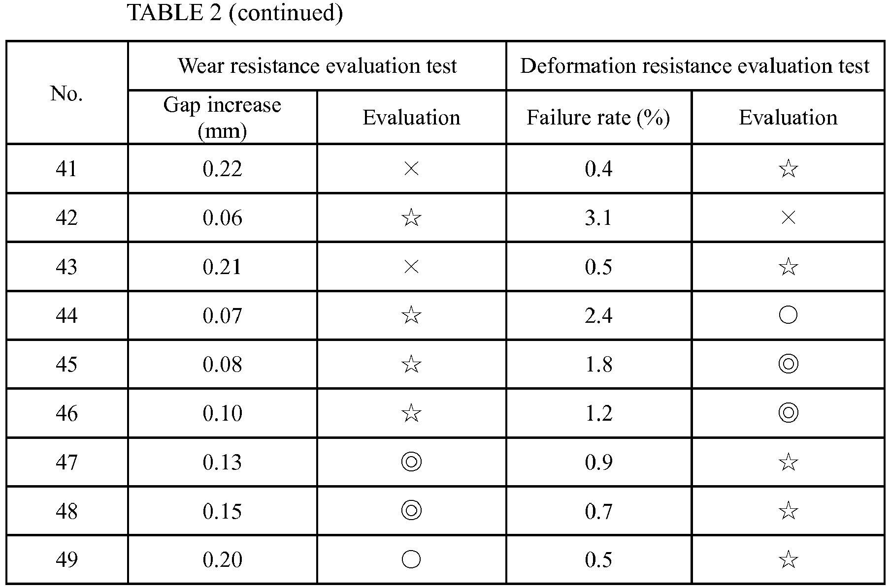
- As indicated in TABLE 2, the sample (Sample No. 43) in which the Ni content of the ground electrode was less than 93 mass% had poor wear resistance even if the hardness of the ground electrode was controlled to 130 to 260 Hv. The reason for this is assumed to be that the ground electrode was low in thermal conductivity due to its relatively low Ni content.
- By contrast, the samples (Sample Nos. 44 to 49) in which the ground electrode was formed with a hardness of 130 to 260 Hv and a Ni content of 93 mass% or more had sufficient performance in terms of both wear resistance and deformation resistance.
- It has been shown by the above test results that it is preferable to control the Ni content of the ground electrode to 93 mass% and to control the hardness of the ground electrode to be 130 to 260 Hv in order to attain sufficient performance in terms of both wear resistance and deformation resistance in the spark plug where the ground electrode is formed with a cross-sectional area of 2.0 mm2 or smaller and concerns about deterioration in wear resistance and deformation resistance arise. It is said that it is more preferable to control the hardness of the ground electrode to be 150 to 240 Hv for further improvements in wear resistance and deformation resistance.
- It is also said that it is more preferable to control the ratio L/S to be 10 or lower and to control the ratio T/W to be 0.6 or higher for further improvement in deformation resistance.
- Further, a plurality of ground electrodes were prepared by adding one or more kinds of rare earth elements (including at least Y) into the ground electrode and varying the total content of the rare earth elements. Each of the ground electrodes was tested by the same deformation resistance evaluation test as above. Spark plug samples were prepared using these ground electrodes and tested by the same wear resistance evaluation test as above. Each of the spark plug samples was also tested by sweating resistance evaluation test and breaking resistance evaluation test.
- The sweating resistance evaluation test was herein performed by the following procedure. First, each of the samples was mounted on a 2000-cc six-cylinder gasoline engine. The engine was then driven at full throttle at an engine rotation speed of 5000 rpm for 100 hours by the use of lead-free gasoline as engine fuel. After the lapse of 100 hours, the surface of the ground electrode was observed. When the surface of the ground electrode had a grain sweating phenomenon (oxide grain formation), the sweating resistance of the sample was marked with "× " upon judging that the sample had a possibility of deterioration in ignition performance or the like under the influence of such a grain sweating phenomenon. When the surface of the ground electrode did not have a sweating phenomenon but was in a rough state (where oxide projections were formed on the surface of the ground electrode), the sweating resistance of the sample was marked with "Δ upon judging that: the appearance of the sample was unfavorable; and the sample had a possibility of adverse effect on ignition performance or the like during use. On the other hand, the sample was evaluated as being good in terms of appearance, ignition performance and the like and marked with "○" when there was no sweating phenomenon and no rough state on the surface of the ground electrode.
- The breaking resistance evaluation test was performed as follows. Each of the samples was subjected to vibrations at a frequency of 40 Hz and at an acceleration of 30 G for 8 hours while heating and maintaining the ground electrode at 1000°C. After the lapse of 8 hours, the occurrence of breakage in the ground electrode was checked. The sample was evaluated as being inferior in breaking resistance and marked with "× " when breakage occurred in the ground electrode. The sample was evaluated as being rather poor in breaking resistance and marked with "Δ" when there occurred no breakage but cracking in the ground electrode. The sample was evaluated as having good breaking resistance and marked with "O" where there was no breakage and no cracking in the ground electrode.
- The test results of the wear resistance evaluation test, deformation resistance evaluation test, sweating resistance evaluation test and breaking resistance evaluation test are indicated in TABLE 3. In each of these evaluation tests, the cross-sectional area of the ground electrode was set to 1.5 mm2; and the hardness of the ground electrode was set to 180 Hv. In each of the samples of the sweating resistance evaluation test and breaking resistance evaluation test, the thread diameter size of the thread portion was set to M12; the protrusion length of the front end portion of the ceramic insulator from the front end of the metal shell was set to 3 mm; and the protrusion length of the front end portion of the center electrode from the front end of the ceramic insulator was set to 3 mm. The size of the spark discharge gap before the test was set to 0.8 mm; and the outer diameter of the front end portion of the center electrode was set to 2.5 mm. Further, the ratio L/S was set to 6; and the ratio T/W was set to 0.8 in each sample.


- As indicated in TABLE 3, the samples (Sample Nos. 52 to 54) in which the total rare earth element content was 0.05 to 0.45 mass% had both good sweating resistance and good breaking resistance.
- It has thus been shown by the above test results that it is preferable to not only add at least one or more kinds of rare earth elements into the ground electrode but also to control the total rare earth element content of the ground electrode to be 0.05 to 0.45 mass% for improvements in sweating resistance and breaking resistance.
- The present invention is not limited to the above-mentioned embodiment and may be embodied as follows. It is needless to say that any application and modification examples other than those indicated below are possible.
- (a) In the above embodiment, the
ground electrode 27 is rectangular in cross section. It is alternatively feasible to provide aground electrode 37 that has a flat surface 37S facing thecenter electrode 5 and a convexcurved back surface 37W located opposite the flat surface 37S as shown inFIG. 5(a) , or to provide aground electrode 47 that has aflat surface 47S facing thecenter electrode 5, a flat back surface 47H located opposite theflat surface 47S and opposite, convex curved side surfaces 47W1 and 47W2 extending between theflat surface 47S and the back surface 47H as shown inFIG. 5(b) . In either case, it is easier that the fuel gas will flow into thespark discharge gap 28 around theground electrode cross-section ground electrode 27, theground electrode ground electrode - (b) Although the
spark discharge gap 28 is defined between the front end portion of thecenter electrode 5 and the distal end portion of theground electrode 27 in the above embodiment, it is alternatively feasible to fix a noble metal tip of noble metal alloy (e.g. platinum alloy or iridium alloy) to either one or both of theseelectrodes spark discharge gap 28 between the noble metal tip on the one electrode 5 (27) and the other electrode 27 (5) or between the noble metal tips on therespective electrodes ground electrode 27, the hardness of theground electrode 27 is measured at any part other than that where there occurs a change in hardness due to the joining of the noble metal chip (e.g. at a position of 1.5 mm or more apart from a lateral surface of the noble metal tip). - (c) In the above embodiment, the ground-
electrode metal member 32 is formed as the material for production of theground electrode 27 by subjecting thesemi-processed member 31 to plastic working (such as rolling or wiredrawing) and thereby increasing the hardness of thesemi-processed member 31. It is alternatively feasible to form the ground-electrode metal member 32 by heat treating thesemi-processed member 31 and thereby decreasing the hardness of thesemi-processed member 31. More specifically, the ground-electrode metal member 32 can be formed with a hardness of 130 to 260 Hv by, after subjecting thesemi-processed member 31 to plastic working (e.g. wiredrawing) so as to increase the hardness of thesemi-processed member 31 to be 130 Hv or higher and control the cross-sectional area of thesemi-processed member 31 to a sufficiently small level of 2.0 mm2 or smaller, subjecting thesemi-processed member 31 to heat treatment (e.g. annealing) so as to decrease the hardness of thesemi-processed member 31, and then, cutting thesemi-processed member 31 to a given length. It is herein necessary to adjust the heating time and heating temperature during the heat treatment in such a manner that the hardness of thesemi-processed member 31 does not become excessively low. The heat treatment may be conducted after the cutting of thesemi-processed member 31. - (d) Although the
tool engagement portion 19 is hexagonal in cross section in the above embodiment, the shape of thetool engagement portion 19 is not limited to such a hexagonal cross-section shape. Thetool engagement portion 19 may alternatively be formed into a Bi-HEX shape (modified dodecagonal shape) (according to ISO 22977: 2005(E)) or the like. -
- 1:
- Spark plug
- 2:
- Insulator (Ceramic insulator)
- 3:
- Metal shell
- 4:
- Axial hole
- 5:
- Center electrode
- 27:
- Ground electrode
- 28:
- Spark discharge gap (gap)
- 31:
- Semi-processed member
- 32:
- Ground-electrode metal material
- 37W, 47W1, 47W2:
- Curved surface
- CL1:
- Axis
- CL2
- Center line (of ground electrode)
Claims (9)
- A spark plug, comprising:a cylindrical insulator having an axial hole formed therethrough in an axis direction of the spark plug;a center electrode inserted in a front side of the axial hole;a cylindrical metal shell disposed around the insulator; anda ground electrode joined to a front end portion of the metal shell in such a manner as to define a gap between the center electrode and the ground electrode,wherein the ground electrode is made of a metal material containing 93 mass% or more of nickel;wherein the ground electrode has a cross-sectional area of 2.0 mm2 or smaller in any arbitrary cross section thereof taken in a direction perpendicular to a center line of the ground electrode; andwherein the ground electrode has a hardness of 130 to 260 Hv in terms of Vickers hardness.
- The spark plug according to claim 1, wherein the ground electrode has a hardness of 150 to 240 Hv in terms of Vickers hardness.
- The spark plug according to claim 1 or 2, wherein the ground electrode has a ratio L/S (1/mm) of 3 to 10 where S is a maximum cross-sectional area of the cross section of the ground electrode taken perpendicular to the center line of the ground electrode and L is a length of the ground electrode along the center line of the ground electrode.
- The spark plug according to any one of claims 1 to 3, wherein the ground electrode has a flat surface facing the center electrode and a convex curved back surface located opposite the flat surface.
- The spark plug according to any one of claims 1 to 4, wherein the ground electrode has a flat surface facing the center electrode, a flat back surface located opposite the flat surface and opposite, convex curved side surfaces extending between the flat surface and back surface of the ground electrode.
- The spark plug according to any one of claims 1 to 5, wherein the ground electrode has a ratio T/W of 0.6 or larger where T (mm) is a thickness of the ground electrode and W (mm) is a width of the ground electrode.
- The spark plug according to any one of claims 1 to 6, wherein the metal material of the ground electrode contains one or more kinds of rare earth elements in a total amount of 0.05 to 0.45 mass%.
- The spark plug according to any one of claims 1 to 7, wherein at least a part of a surface of the ground electrode is covered with a plating layer.
- A method for manufacturing the spark plug according to any one of claims 1 to 8, comprising a metal member forming step of forming a ground-electrode metal member for the production of the ground electrode,
wherein the metal member forming step includes
a softening step of allowing a semi-processed member of metal material containing 93 mass% or more ofNi to undergo heat treatment so as to decrease the hardness of the semi-processed member; and
a hardening step of, after the softening step, subjecting the semi-processed member to plastic working so as to increase the hardness of the semi-processed member and thereby complete the semi-processed member as the ground-electrode metal member.
Applications Claiming Priority (2)
| Application Number | Priority Date | Filing Date | Title |
|---|---|---|---|
| JP2010282507 | 2010-12-20 | ||
| PCT/JP2011/073064 WO2012086292A1 (en) | 2010-12-20 | 2011-10-06 | Spark plug and manufacturing method therefor |
Publications (3)
| Publication Number | Publication Date |
|---|---|
| EP2658051A1 true EP2658051A1 (en) | 2013-10-30 |
| EP2658051A4 EP2658051A4 (en) | 2014-12-31 |
| EP2658051B1 EP2658051B1 (en) | 2019-12-25 |
Family
ID=46313576
Family Applications (1)
| Application Number | Title | Priority Date | Filing Date |
|---|---|---|---|
| EP11851707.7A Active EP2658051B1 (en) | 2010-12-20 | 2011-10-06 | Spark plug and manufacturing method therefor |
Country Status (6)
| Country | Link |
|---|---|
| US (1) | US9768588B2 (en) |
| EP (1) | EP2658051B1 (en) |
| JP (1) | JP5238096B2 (en) |
| CN (1) | CN103283098B (en) |
| BR (1) | BR112013015609A2 (en) |
| WO (1) | WO2012086292A1 (en) |
Families Citing this family (8)
| Publication number | Priority date | Publication date | Assignee | Title |
|---|---|---|---|---|
| JP5606404B2 (en) * | 2011-07-11 | 2014-10-15 | 日本特殊陶業株式会社 | Spark plug |
| JP5903008B2 (en) * | 2012-07-23 | 2016-04-13 | 日本特殊陶業株式会社 | Spark plug |
| JP5695609B2 (en) * | 2012-08-06 | 2015-04-08 | 日本特殊陶業株式会社 | Spark plug |
| US9252569B2 (en) * | 2012-11-19 | 2016-02-02 | Ngk Spark Plug Co., Ltd. | Spark plug |
| DE102013004365B4 (en) * | 2013-03-14 | 2015-09-24 | VDM Metals GmbH | Nickel-based alloy with silicon, aluminum and chrome |
| JP5990216B2 (en) * | 2014-05-21 | 2016-09-07 | 日本特殊陶業株式会社 | Spark plug |
| DE102015214057B4 (en) * | 2015-07-24 | 2017-12-28 | Ford Global Technologies, Llc | Method for producing a spark plug by means of a capsule filled with powder and spark plug |
| JP7165644B2 (en) * | 2019-11-29 | 2022-11-04 | 日本特殊陶業株式会社 | Spark plug |
Citations (4)
| Publication number | Priority date | Publication date | Assignee | Title |
|---|---|---|---|---|
| EP1237244A2 (en) * | 2001-02-28 | 2002-09-04 | Ngk Spark Plug Co., Ltd. | Spark plug and method of producing spark plug |
| EP1241754A2 (en) * | 2001-03-15 | 2002-09-18 | Denso Corporation | Spark plug for an internal combustion engine |
| JP2009094047A (en) * | 2007-09-18 | 2009-04-30 | Ngk Spark Plug Co Ltd | Spark plug for internal combustion engine |
| EP2161802A2 (en) * | 2008-09-02 | 2010-03-10 | Ngk Spark Plug Co., Ltd | Spark plug |
Family Cites Families (14)
| Publication number | Priority date | Publication date | Assignee | Title |
|---|---|---|---|---|
| JPS5947436B2 (en) * | 1982-01-14 | 1984-11-19 | 株式会社デンソー | Spark plug for internal combustion engine |
| US5204059A (en) * | 1988-07-25 | 1993-04-20 | Mitsubishi Metal Corporation | Ni base alloy for spark plug electrodes of internal combustion engines |
| JPH10251786A (en) * | 1997-03-11 | 1998-09-22 | Hitachi Metals Ltd | Electrode material for spark plug |
| JP2003197345A (en) * | 2001-12-25 | 2003-07-11 | Denso Corp | Manufacturing method of spark plug |
| JP2003229231A (en) * | 2002-02-05 | 2003-08-15 | Denso Corp | Production method of spark plug |
| JP4699867B2 (en) * | 2004-11-04 | 2011-06-15 | 日立金属株式会社 | Spark plug electrode material |
| JP4762109B2 (en) | 2006-10-24 | 2011-08-31 | 株式会社日本自動車部品総合研究所 | Spark plug for internal combustion engine |
| JP4413951B2 (en) | 2007-07-06 | 2010-02-10 | 日本特殊陶業株式会社 | Spark plug |
| JP5245578B2 (en) * | 2007-07-31 | 2013-07-24 | 株式会社デンソー | Spark plug for internal combustion engine |
| CN101689753B (en) | 2007-08-08 | 2012-05-23 | 日本特殊陶业株式会社 | Spark plug and its manufacturing method |
| WO2009084575A1 (en) | 2007-12-28 | 2009-07-09 | Ngk Spark Plug Co., Ltd. | Spark plug for internal combustion engine |
| JP5016569B2 (en) * | 2008-08-21 | 2012-09-05 | 日本特殊陶業株式会社 | Spark plug manufacturing method and plating removal apparatus |
| CN102138260B (en) * | 2008-09-02 | 2013-07-31 | 日本特殊陶业株式会社 | Spark plug |
| JP4921540B2 (en) * | 2009-11-26 | 2012-04-25 | 日本特殊陶業株式会社 | Electrode material for spark plug |
-
2011
- 2011-10-06 JP JP2012511467A patent/JP5238096B2/en active Active
- 2011-10-06 BR BR112013015609-0A patent/BR112013015609A2/en not_active Application Discontinuation
- 2011-10-06 US US13/877,352 patent/US9768588B2/en active Active
- 2011-10-06 WO PCT/JP2011/073064 patent/WO2012086292A1/en active Application Filing
- 2011-10-06 EP EP11851707.7A patent/EP2658051B1/en active Active
- 2011-10-06 CN CN201180061371.5A patent/CN103283098B/en active Active
Patent Citations (4)
| Publication number | Priority date | Publication date | Assignee | Title |
|---|---|---|---|---|
| EP1237244A2 (en) * | 2001-02-28 | 2002-09-04 | Ngk Spark Plug Co., Ltd. | Spark plug and method of producing spark plug |
| EP1241754A2 (en) * | 2001-03-15 | 2002-09-18 | Denso Corporation | Spark plug for an internal combustion engine |
| JP2009094047A (en) * | 2007-09-18 | 2009-04-30 | Ngk Spark Plug Co Ltd | Spark plug for internal combustion engine |
| EP2161802A2 (en) * | 2008-09-02 | 2010-03-10 | Ngk Spark Plug Co., Ltd | Spark plug |
Non-Patent Citations (1)
| Title |
|---|
| See also references of WO2012086292A1 * |
Also Published As
| Publication number | Publication date |
|---|---|
| EP2658051A4 (en) | 2014-12-31 |
| CN103283098B (en) | 2016-05-04 |
| EP2658051B1 (en) | 2019-12-25 |
| WO2012086292A1 (en) | 2012-06-28 |
| US9768588B2 (en) | 2017-09-19 |
| BR112013015609A2 (en) | 2018-07-24 |
| JPWO2012086292A1 (en) | 2014-05-22 |
| US20130200774A1 (en) | 2013-08-08 |
| CN103283098A (en) | 2013-09-04 |
| JP5238096B2 (en) | 2013-07-17 |
Similar Documents
| Publication | Publication Date | Title |
|---|---|---|
| EP2658051B1 (en) | Spark plug and manufacturing method therefor | |
| JP5341752B2 (en) | Spark plug for internal combustion engine and method for manufacturing the same | |
| EP2175535B1 (en) | Spark plug for internal combustion engine | |
| EP2479855B1 (en) | Spark plug | |
| EP2348590B1 (en) | Spark plug for internal combustion engine | |
| EP2408071B1 (en) | Spark plug for internal combustion engine and method of manufacturing same | |
| EP2020713B1 (en) | Spark plug for internal combustion engine and method of manufacturing the same | |
| EP2073327B1 (en) | Spark plug for internal combustion engine | |
| EP2393171A1 (en) | Spark plug and process for producing same | |
| EP2461437B1 (en) | Spark plug | |
| EP2634873B1 (en) | Spark plug | |
| EP2658050B1 (en) | Spark plug | |
| EP2571118B1 (en) | Spark plug | |
| EP2579401B1 (en) | Spark plug | |
| JP2007227189A (en) | Spark plug for internal combustion engine and manufacturing method | |
| US8368293B2 (en) | Spark plug and method of manufacturing the same | |
| EP2555355B1 (en) | Spark plug | |
| EP3065238B1 (en) | Spark plug | |
| EP2624383B1 (en) | Spark plug | |
| JP2013127911A (en) | Spark plug and manufacturing method thereof | |
| EP3270475B1 (en) | Spark plug | |
| JP5564070B2 (en) | Spark plug |
Legal Events
| Date | Code | Title | Description |
|---|---|---|---|
| PUAI | Public reference made under article 153(3) epc to a published international application that has entered the european phase |
Free format text: ORIGINAL CODE: 0009012 |
|
| 17P | Request for examination filed |
Effective date: 20130712 |
|
| AK | Designated contracting states |
Kind code of ref document: A1 Designated state(s): AL AT BE BG CH CY CZ DE DK EE ES FI FR GB GR HR HU IE IS IT LI LT LU LV MC MK MT NL NO PL PT RO RS SE SI SK SM TR |
|
| DAX | Request for extension of the european patent (deleted) | ||
| A4 | Supplementary search report drawn up and despatched |
Effective date: 20141128 |
|
| RIC1 | Information provided on ipc code assigned before grant |
Ipc: H01T 13/32 20060101AFI20141124BHEP Ipc: H01T 13/39 20060101ALI20141124BHEP |
|
| GRAP | Despatch of communication of intention to grant a patent |
Free format text: ORIGINAL CODE: EPIDOSNIGR1 |
|
| STAA | Information on the status of an ep patent application or granted ep patent |
Free format text: STATUS: GRANT OF PATENT IS INTENDED |
|
| INTG | Intention to grant announced |
Effective date: 20190719 |
|
| GRAS | Grant fee paid |
Free format text: ORIGINAL CODE: EPIDOSNIGR3 |
|
| GRAA | (expected) grant |
Free format text: ORIGINAL CODE: 0009210 |
|
| STAA | Information on the status of an ep patent application or granted ep patent |
Free format text: STATUS: THE PATENT HAS BEEN GRANTED |
|
| AK | Designated contracting states |
Kind code of ref document: B1 Designated state(s): AL AT BE BG CH CY CZ DE DK EE ES FI FR GB GR HR HU IE IS IT LI LT LU LV MC MK MT NL NO PL PT RO RS SE SI SK SM TR |
|
| REG | Reference to a national code |
Ref country code: GB Ref legal event code: FG4D |
|
| REG | Reference to a national code |
Ref country code: CH Ref legal event code: EP |
|
| REG | Reference to a national code |
Ref country code: AT Ref legal event code: REF Ref document number: 1218175 Country of ref document: AT Kind code of ref document: T Effective date: 20200115 |
|
| REG | Reference to a national code |
Ref country code: DE Ref legal event code: R096 Ref document number: 602011064284 Country of ref document: DE |
|
| REG | Reference to a national code |
Ref country code: IE Ref legal event code: FG4D |
|
| REG | Reference to a national code |
Ref country code: NL Ref legal event code: MP Effective date: 20191225 |
|
| PG25 | Lapsed in a contracting state [announced via postgrant information from national office to epo] |
Ref country code: LT Free format text: LAPSE BECAUSE OF FAILURE TO SUBMIT A TRANSLATION OF THE DESCRIPTION OR TO PAY THE FEE WITHIN THE PRESCRIBED TIME-LIMIT Effective date: 20191225 Ref country code: FI Free format text: LAPSE BECAUSE OF FAILURE TO SUBMIT A TRANSLATION OF THE DESCRIPTION OR TO PAY THE FEE WITHIN THE PRESCRIBED TIME-LIMIT Effective date: 20191225 Ref country code: SE Free format text: LAPSE BECAUSE OF FAILURE TO SUBMIT A TRANSLATION OF THE DESCRIPTION OR TO PAY THE FEE WITHIN THE PRESCRIBED TIME-LIMIT Effective date: 20191225 Ref country code: BG Free format text: LAPSE BECAUSE OF FAILURE TO SUBMIT A TRANSLATION OF THE DESCRIPTION OR TO PAY THE FEE WITHIN THE PRESCRIBED TIME-LIMIT Effective date: 20200325 Ref country code: LV Free format text: LAPSE BECAUSE OF FAILURE TO SUBMIT A TRANSLATION OF THE DESCRIPTION OR TO PAY THE FEE WITHIN THE PRESCRIBED TIME-LIMIT Effective date: 20191225 Ref country code: GR Free format text: LAPSE BECAUSE OF FAILURE TO SUBMIT A TRANSLATION OF THE DESCRIPTION OR TO PAY THE FEE WITHIN THE PRESCRIBED TIME-LIMIT Effective date: 20200326 Ref country code: NO Free format text: LAPSE BECAUSE OF FAILURE TO SUBMIT A TRANSLATION OF THE DESCRIPTION OR TO PAY THE FEE WITHIN THE PRESCRIBED TIME-LIMIT Effective date: 20200325 |
|
| REG | Reference to a national code |
Ref country code: LT Ref legal event code: MG4D |
|
| PG25 | Lapsed in a contracting state [announced via postgrant information from national office to epo] |
Ref country code: RS Free format text: LAPSE BECAUSE OF FAILURE TO SUBMIT A TRANSLATION OF THE DESCRIPTION OR TO PAY THE FEE WITHIN THE PRESCRIBED TIME-LIMIT Effective date: 20191225 Ref country code: HR Free format text: LAPSE BECAUSE OF FAILURE TO SUBMIT A TRANSLATION OF THE DESCRIPTION OR TO PAY THE FEE WITHIN THE PRESCRIBED TIME-LIMIT Effective date: 20191225 |
|
| PG25 | Lapsed in a contracting state [announced via postgrant information from national office to epo] |
Ref country code: AL Free format text: LAPSE BECAUSE OF FAILURE TO SUBMIT A TRANSLATION OF THE DESCRIPTION OR TO PAY THE FEE WITHIN THE PRESCRIBED TIME-LIMIT Effective date: 20191225 |
|
| PG25 | Lapsed in a contracting state [announced via postgrant information from national office to epo] |
Ref country code: PT Free format text: LAPSE BECAUSE OF FAILURE TO SUBMIT A TRANSLATION OF THE DESCRIPTION OR TO PAY THE FEE WITHIN THE PRESCRIBED TIME-LIMIT Effective date: 20200520 Ref country code: RO Free format text: LAPSE BECAUSE OF FAILURE TO SUBMIT A TRANSLATION OF THE DESCRIPTION OR TO PAY THE FEE WITHIN THE PRESCRIBED TIME-LIMIT Effective date: 20191225 Ref country code: CZ Free format text: LAPSE BECAUSE OF FAILURE TO SUBMIT A TRANSLATION OF THE DESCRIPTION OR TO PAY THE FEE WITHIN THE PRESCRIBED TIME-LIMIT Effective date: 20191225 Ref country code: NL Free format text: LAPSE BECAUSE OF FAILURE TO SUBMIT A TRANSLATION OF THE DESCRIPTION OR TO PAY THE FEE WITHIN THE PRESCRIBED TIME-LIMIT Effective date: 20191225 Ref country code: EE Free format text: LAPSE BECAUSE OF FAILURE TO SUBMIT A TRANSLATION OF THE DESCRIPTION OR TO PAY THE FEE WITHIN THE PRESCRIBED TIME-LIMIT Effective date: 20191225 |
|
| PG25 | Lapsed in a contracting state [announced via postgrant information from national office to epo] |
Ref country code: IS Free format text: LAPSE BECAUSE OF FAILURE TO SUBMIT A TRANSLATION OF THE DESCRIPTION OR TO PAY THE FEE WITHIN THE PRESCRIBED TIME-LIMIT Effective date: 20200425 Ref country code: SM Free format text: LAPSE BECAUSE OF FAILURE TO SUBMIT A TRANSLATION OF THE DESCRIPTION OR TO PAY THE FEE WITHIN THE PRESCRIBED TIME-LIMIT Effective date: 20191225 Ref country code: SK Free format text: LAPSE BECAUSE OF FAILURE TO SUBMIT A TRANSLATION OF THE DESCRIPTION OR TO PAY THE FEE WITHIN THE PRESCRIBED TIME-LIMIT Effective date: 20191225 |
|
| REG | Reference to a national code |
Ref country code: DE Ref legal event code: R097 Ref document number: 602011064284 Country of ref document: DE |
|
| PG25 | Lapsed in a contracting state [announced via postgrant information from national office to epo] |
Ref country code: DK Free format text: LAPSE BECAUSE OF FAILURE TO SUBMIT A TRANSLATION OF THE DESCRIPTION OR TO PAY THE FEE WITHIN THE PRESCRIBED TIME-LIMIT Effective date: 20191225 Ref country code: ES Free format text: LAPSE BECAUSE OF FAILURE TO SUBMIT A TRANSLATION OF THE DESCRIPTION OR TO PAY THE FEE WITHIN THE PRESCRIBED TIME-LIMIT Effective date: 20191225 |
|
| PLBE | No opposition filed within time limit |
Free format text: ORIGINAL CODE: 0009261 |
|
| STAA | Information on the status of an ep patent application or granted ep patent |
Free format text: STATUS: NO OPPOSITION FILED WITHIN TIME LIMIT |
|
| REG | Reference to a national code |
Ref country code: AT Ref legal event code: MK05 Ref document number: 1218175 Country of ref document: AT Kind code of ref document: T Effective date: 20191225 |
|
| PG25 | Lapsed in a contracting state [announced via postgrant information from national office to epo] |
Ref country code: SI Free format text: LAPSE BECAUSE OF FAILURE TO SUBMIT A TRANSLATION OF THE DESCRIPTION OR TO PAY THE FEE WITHIN THE PRESCRIBED TIME-LIMIT Effective date: 20191225 |
|
| 26N | No opposition filed |
Effective date: 20200928 |
|
| PG25 | Lapsed in a contracting state [announced via postgrant information from national office to epo] |
Ref country code: IT Free format text: LAPSE BECAUSE OF FAILURE TO SUBMIT A TRANSLATION OF THE DESCRIPTION OR TO PAY THE FEE WITHIN THE PRESCRIBED TIME-LIMIT Effective date: 20191225 Ref country code: AT Free format text: LAPSE BECAUSE OF FAILURE TO SUBMIT A TRANSLATION OF THE DESCRIPTION OR TO PAY THE FEE WITHIN THE PRESCRIBED TIME-LIMIT Effective date: 20191225 |
|
| PG25 | Lapsed in a contracting state [announced via postgrant information from national office to epo] |
Ref country code: PL Free format text: LAPSE BECAUSE OF FAILURE TO SUBMIT A TRANSLATION OF THE DESCRIPTION OR TO PAY THE FEE WITHIN THE PRESCRIBED TIME-LIMIT Effective date: 20191225 |
|
| REG | Reference to a national code |
Ref country code: CH Ref legal event code: PL |
|
| GBPC | Gb: european patent ceased through non-payment of renewal fee |
Effective date: 20201006 |
|
| PG25 | Lapsed in a contracting state [announced via postgrant information from national office to epo] |
Ref country code: MC Free format text: LAPSE BECAUSE OF FAILURE TO SUBMIT A TRANSLATION OF THE DESCRIPTION OR TO PAY THE FEE WITHIN THE PRESCRIBED TIME-LIMIT Effective date: 20191225 Ref country code: LU Free format text: LAPSE BECAUSE OF NON-PAYMENT OF DUE FEES Effective date: 20201006 |
|
| REG | Reference to a national code |
Ref country code: BE Ref legal event code: MM Effective date: 20201031 |
|
| PG25 | Lapsed in a contracting state [announced via postgrant information from national office to epo] |
Ref country code: FR Free format text: LAPSE BECAUSE OF NON-PAYMENT OF DUE FEES Effective date: 20201031 |
|
| PG25 | Lapsed in a contracting state [announced via postgrant information from national office to epo] |
Ref country code: GB Free format text: LAPSE BECAUSE OF NON-PAYMENT OF DUE FEES Effective date: 20201006 Ref country code: LI Free format text: LAPSE BECAUSE OF NON-PAYMENT OF DUE FEES Effective date: 20201031 Ref country code: BE Free format text: LAPSE BECAUSE OF NON-PAYMENT OF DUE FEES Effective date: 20201031 Ref country code: CH Free format text: LAPSE BECAUSE OF NON-PAYMENT OF DUE FEES Effective date: 20201031 |
|
| PG25 | Lapsed in a contracting state [announced via postgrant information from national office to epo] |
Ref country code: IE Free format text: LAPSE BECAUSE OF NON-PAYMENT OF DUE FEES Effective date: 20201006 |
|
| PG25 | Lapsed in a contracting state [announced via postgrant information from national office to epo] |
Ref country code: TR Free format text: LAPSE BECAUSE OF FAILURE TO SUBMIT A TRANSLATION OF THE DESCRIPTION OR TO PAY THE FEE WITHIN THE PRESCRIBED TIME-LIMIT Effective date: 20191225 Ref country code: MT Free format text: LAPSE BECAUSE OF FAILURE TO SUBMIT A TRANSLATION OF THE DESCRIPTION OR TO PAY THE FEE WITHIN THE PRESCRIBED TIME-LIMIT Effective date: 20191225 Ref country code: CY Free format text: LAPSE BECAUSE OF FAILURE TO SUBMIT A TRANSLATION OF THE DESCRIPTION OR TO PAY THE FEE WITHIN THE PRESCRIBED TIME-LIMIT Effective date: 20191225 |
|
| PG25 | Lapsed in a contracting state [announced via postgrant information from national office to epo] |
Ref country code: MK Free format text: LAPSE BECAUSE OF FAILURE TO SUBMIT A TRANSLATION OF THE DESCRIPTION OR TO PAY THE FEE WITHIN THE PRESCRIBED TIME-LIMIT Effective date: 20191225 |
|
| P01 | Opt-out of the competence of the unified patent court (upc) registered |
Effective date: 20230512 |
|
| REG | Reference to a national code |
Ref country code: DE Ref legal event code: R081 Ref document number: 602011064284 Country of ref document: DE Owner name: NITERRA CO., LTD., NAGOYA-SHI, JP Free format text: FORMER OWNER: NGK SPARK PLUG CO., LTD., NAGOYA-SHI, AICHI, JP |
|
| PGFP | Annual fee paid to national office [announced via postgrant information from national office to epo] |
Ref country code: DE Payment date: 20230830 Year of fee payment: 13 |