EP2668922A1 - System and method for tissue sealing - Google Patents
System and method for tissue sealing Download PDFInfo
- Publication number
- EP2668922A1 EP2668922A1 EP13169684.1A EP13169684A EP2668922A1 EP 2668922 A1 EP2668922 A1 EP 2668922A1 EP 13169684 A EP13169684 A EP 13169684A EP 2668922 A1 EP2668922 A1 EP 2668922A1
- Authority
- EP
- European Patent Office
- Prior art keywords
- impedance
- tissue
- electrosurgical
- target
- controller
- Prior art date
- Legal status (The legal status is an assumption and is not a legal conclusion. Google has not performed a legal analysis and makes no representation as to the accuracy of the status listed.)
- Granted
Links
- 238000000034 method Methods 0.000 title claims description 48
- 238000007789 sealing Methods 0.000 title description 48
- 239000012530 fluid Substances 0.000 claims abstract description 21
- 230000008859 change Effects 0.000 claims abstract description 13
- 238000009835 boiling Methods 0.000 claims abstract description 9
- 230000004044 response Effects 0.000 claims description 13
- 238000002847 impedance measurement Methods 0.000 claims description 3
- 210000001519 tissue Anatomy 0.000 description 203
- 239000012636 effector Substances 0.000 description 16
- 238000001816 cooling Methods 0.000 description 13
- 230000006870 function Effects 0.000 description 13
- 230000008569 process Effects 0.000 description 13
- 230000007246 mechanism Effects 0.000 description 10
- 230000000875 corresponding effect Effects 0.000 description 9
- 230000004913 activation Effects 0.000 description 3
- 230000008901 benefit Effects 0.000 description 3
- 230000001276 controlling effect Effects 0.000 description 3
- 230000007423 decrease Effects 0.000 description 3
- 230000003247 decreasing effect Effects 0.000 description 3
- 230000000694 effects Effects 0.000 description 3
- 230000004927 fusion Effects 0.000 description 3
- 230000004048 modification Effects 0.000 description 3
- 238000012986 modification Methods 0.000 description 3
- 102000008186 Collagen Human genes 0.000 description 2
- 108010035532 Collagen Proteins 0.000 description 2
- 230000009471 action Effects 0.000 description 2
- 230000001112 coagulating effect Effects 0.000 description 2
- 229920001436 collagen Polymers 0.000 description 2
- 230000002596 correlated effect Effects 0.000 description 2
- 230000001186 cumulative effect Effects 0.000 description 2
- 238000010586 diagram Methods 0.000 description 2
- 230000000116 mitigating effect Effects 0.000 description 2
- 230000000630 rising effect Effects 0.000 description 2
- 230000001052 transient effect Effects 0.000 description 2
- 102000016942 Elastin Human genes 0.000 description 1
- 108010014258 Elastin Proteins 0.000 description 1
- 239000012190 activator Substances 0.000 description 1
- 230000003044 adaptive effect Effects 0.000 description 1
- 230000000712 assembly Effects 0.000 description 1
- 238000000429 assembly Methods 0.000 description 1
- 210000004027 cell Anatomy 0.000 description 1
- 230000015271 coagulation Effects 0.000 description 1
- 238000005345 coagulation Methods 0.000 description 1
- 238000004891 communication Methods 0.000 description 1
- 238000010276 construction Methods 0.000 description 1
- 238000012937 correction Methods 0.000 description 1
- 229920002549 elastin Polymers 0.000 description 1
- 238000012976 endoscopic surgical procedure Methods 0.000 description 1
- 210000003722 extracellular fluid Anatomy 0.000 description 1
- 238000010438 heat treatment Methods 0.000 description 1
- 230000023597 hemostasis Effects 0.000 description 1
- 239000012212 insulator Substances 0.000 description 1
- 230000003993 interaction Effects 0.000 description 1
- 230000003834 intracellular effect Effects 0.000 description 1
- 210000002977 intracellular fluid Anatomy 0.000 description 1
- 238000012544 monitoring process Methods 0.000 description 1
- 238000002355 open surgical procedure Methods 0.000 description 1
- 230000003287 optical effect Effects 0.000 description 1
- 230000000737 periodic effect Effects 0.000 description 1
- 230000002085 persistent effect Effects 0.000 description 1
- 238000003825 pressing Methods 0.000 description 1
- 230000001105 regulatory effect Effects 0.000 description 1
- 238000005070 sampling Methods 0.000 description 1
- 239000000126 substance Substances 0.000 description 1
- 238000001356 surgical procedure Methods 0.000 description 1
- 238000012795 verification Methods 0.000 description 1
- 230000000007 visual effect Effects 0.000 description 1
Images


Classifications
-
- A—HUMAN NECESSITIES
- A61—MEDICAL OR VETERINARY SCIENCE; HYGIENE
- A61B—DIAGNOSIS; SURGERY; IDENTIFICATION
- A61B18/00—Surgical instruments, devices or methods for transferring non-mechanical forms of energy to or from the body
- A61B18/04—Surgical instruments, devices or methods for transferring non-mechanical forms of energy to or from the body by heating
- A61B18/12—Surgical instruments, devices or methods for transferring non-mechanical forms of energy to or from the body by heating by passing a current through the tissue to be heated, e.g. high-frequency current
- A61B18/14—Probes or electrodes therefor
- A61B18/1442—Probes having pivoting end effectors, e.g. forceps
- A61B18/1445—Probes having pivoting end effectors, e.g. forceps at the distal end of a shaft, e.g. forceps or scissors at the end of a rigid rod
-
- A—HUMAN NECESSITIES
- A61—MEDICAL OR VETERINARY SCIENCE; HYGIENE
- A61B—DIAGNOSIS; SURGERY; IDENTIFICATION
- A61B18/00—Surgical instruments, devices or methods for transferring non-mechanical forms of energy to or from the body
- A61B2018/00571—Surgical instruments, devices or methods for transferring non-mechanical forms of energy to or from the body for achieving a particular surgical effect
- A61B2018/0063—Sealing
-
- A—HUMAN NECESSITIES
- A61—MEDICAL OR VETERINARY SCIENCE; HYGIENE
- A61B—DIAGNOSIS; SURGERY; IDENTIFICATION
- A61B18/00—Surgical instruments, devices or methods for transferring non-mechanical forms of energy to or from the body
- A61B2018/00636—Sensing and controlling the application of energy
- A61B2018/00666—Sensing and controlling the application of energy using a threshold value
-
- A—HUMAN NECESSITIES
- A61—MEDICAL OR VETERINARY SCIENCE; HYGIENE
- A61B—DIAGNOSIS; SURGERY; IDENTIFICATION
- A61B18/00—Surgical instruments, devices or methods for transferring non-mechanical forms of energy to or from the body
- A61B2018/00636—Sensing and controlling the application of energy
- A61B2018/00684—Sensing and controlling the application of energy using lookup tables
-
- A—HUMAN NECESSITIES
- A61—MEDICAL OR VETERINARY SCIENCE; HYGIENE
- A61B—DIAGNOSIS; SURGERY; IDENTIFICATION
- A61B18/00—Surgical instruments, devices or methods for transferring non-mechanical forms of energy to or from the body
- A61B2018/00636—Sensing and controlling the application of energy
- A61B2018/00773—Sensed parameters
- A61B2018/00875—Resistance or impedance
-
- A—HUMAN NECESSITIES
- A61—MEDICAL OR VETERINARY SCIENCE; HYGIENE
- A61B—DIAGNOSIS; SURGERY; IDENTIFICATION
- A61B18/00—Surgical instruments, devices or methods for transferring non-mechanical forms of energy to or from the body
- A61B2018/00988—Means for storing information, e.g. calibration constants, or for preventing excessive use, e.g. usage, service life counter
-
- A—HUMAN NECESSITIES
- A61—MEDICAL OR VETERINARY SCIENCE; HYGIENE
- A61B—DIAGNOSIS; SURGERY; IDENTIFICATION
- A61B90/00—Instruments, implements or accessories specially adapted for surgery or diagnosis and not covered by any of the groups A61B1/00 - A61B50/00, e.g. for luxation treatment or for protecting wound edges
- A61B90/06—Measuring instruments not otherwise provided for
- A61B2090/064—Measuring instruments not otherwise provided for for measuring force, pressure or mechanical tension
- A61B2090/065—Measuring instruments not otherwise provided for for measuring force, pressure or mechanical tension for measuring contact or contact pressure
Definitions
- the present disclosure relates to an electrosurgical system and method for performing electrosurgical procedures. More particularly, the present disclosure relates to sealing tissue, wherein energy is administered to match measured impedance to a desired impedance, and a tissue cooling time is observed prior to the completion of the seal.
- Electrosurgery involves application of high radio frequency electrical current to a surgical site to cut, ablate, or coagulate tissue.
- a source or active electrode delivers radio frequency energy from the electrosurgical generator to the tissue and a return electrode (e.g., a return pad) carries the current back to the generator.
- a return electrode e.g., a return pad
- the source electrode is typically part of the surgical instrument held by the surgeon and applied to the tissue to be treated.
- the patient return electrode is placed remotely from the active electrode to carry the current back to the generator.
- one of the electrodes of the hand-held instrument functions as the active electrode and the other as the return electrode.
- the return electrode is placed in close proximity to the active electrode such that an electrical circuit is formed between the two electrodes (e.g., electrosurgical forceps).
- an electrical circuit is formed between the two electrodes (e.g., electrosurgical forceps).
- the applied electrical current is limited to the body tissue positioned between the electrodes.
- Bipolar electrosurgery generally involves the use of forceps.
- a forceps is a pliers-like instrument which relies on mechanical action between its jaws to grasp, clamp and constrict vessels or tissue. So-called “open forceps” are commonly used in open surgical procedures whereas “endoscopic forceps” or “laparoscopic forceps” are, as the name implies, used for less invasive endoscopic surgical procedures.
- Electrosurgical forceps (open or endoscopic) utilize mechanical clamping action and electrical energy to effect hemostasis on the clamped tissue.
- the forceps include electrosurgically conductive plates which apply electrosurgical energy to the clamped tissue. By controlling the intensity, frequency and duration of the electrosurgical energy applied through the conductive plates to the tissue, the surgeon can coagulate, cauterize and/or seal tissue.
- Tissue or vessel sealing is a process of liquefying the collagen, elastin and ground substances in the tissue so that they reform into a fused mass with significantly-reduced demarcation between the opposing tissue structures.
- Cauterization involves the use of heat to destroy tissue and coagulation is a process of desiccating tissue wherein the tissue cells are ruptured and dried.
- Tissue sealing procedures involve more than simply cauterizing or coagulating tissue to create an effective seal; the procedures involve precise control of a variety of factors. For example, in order to affect a proper seal in vessels or tissue, it has been determined that two predominant mechanical parameters must be accurately controlled: the pressure applied to the tissue; and the gap distance between the electrodes (i.e., distance between opposing jaw members or opposing sealing plates). In addition, electrosurgical energy must be applied to the tissue under controlled conditions to ensure creation of an effective vessel seal. Techniques have been developed whereby the energy applied to the tissue is varied during the tissue sealing process to achieve a desired tissue impedance trajectory. When a target tissue impedance threshold is reached, the tissue seal is deemed completed and the delivery of electrosurgical energy is halted.
- the present disclosure relates to a vessel or tissue sealing system and method.
- an electrosurgical instrument which may be a bipolar forceps having two jaw members configured for grasping tissue.
- Each of the jaw members may include a sealing plate which communicates electrosurgical energy to the tissue.
- the system may transmit an initial interrogatory pulse for determining initial tissue impedance.
- the system may identify characteristics of the electrosurgical instrument.
- the system determines whether tissue reaction has occurred and calculates the desired impedance trajectory.
- the system calculates a target impedance value at each time step based on a predefined desired rate of change of impedance.
- the system then controls measured tissue impedance to match target impedance.
- the system may sense parameters related to the sealing process. For example without limitation, the system may sense a temperature, a tissue type, and/or a fluid type. Additionally or alternatively, the system may determine an aggregate amount of energy delivered during the sealing process. The delivery of energy may be halted when the measured impedance is above threshold for a predetermined period of time.
- the threshold is defined as a specified impedance level above the initial measured impedance value.
- an electrosurgical system includes an electrosurgical generator adapted to supply electrosurgical energy to tissue.
- the electrosurgical generator may include impedance sensing circuitry which measures impedance of tissue, a processor configured to determine whether a tissue reaction has occurred as a function of a minimum impedance value and a predetermined rise in impedance, wherein tissue reaction corresponds to a boiling point of tissue fluid, and an electrosurgical instrument including at least one active electrode adapted to apply electrosurgical energy to tissue.
- the electrosurgical generator may include temperature sensing circuitry and/or fluid sensing circuitry. Additionally or alternatively, the electrosurgical generator may include circuitry for identifying characteristics of an electrosurgical instrument coupled thereto.
- the electrosurgical instrument may include an identification module to enable the electrosurgical generator to identify the instrument.
- the identification module may include at least one resistive element have a resistance value corresponding to a characteristic of the instrument, such as the instrument configuration (i.e., model number), a unique instrument identifier (i.e., serial number) and/or a thermal property of the jaws.
- the identification module may include computer memory (i.e., read-only memory or flash memory), RFID tag, optical tag (i.e., barcode), or other encoding as will be familiar to the skilled artisan.
- the instrument includes a sensor in operable communication with the generator that is configured to sense the included angle between the jaws, which angle may be indicative of the size and/or mass of tissue held therebetween.
- the generator may use an algorithm or a lookup table to determine a desired cool-down time based upon the identification module.
- an electrosurgical generator includes an RF output stage configured to supply electrosurgical energy to tissue via at least one active electrode configured to apply electrosurgical energy to tissue; sensing circuitry configured to measure impedance of tissue; and a controller.
- the controller is configured to determine whether a tissue reaction has occurred as a function of a minimum impedance value and a predetermined rise in impedance, wherein tissue reaction corresponds to a boiling point of tissue fluid; generate a target impedance trajectory as a function of measured impedance and desired rate of change based on the tissue reaction determination, wherein the target impedance trajectory includes a plurality of target impedance values; and drive tissue impedance along the target impedance trajectory by adjusting the output level of the electrosurgical generator to substantially match tissue impedance to a corresponding target impedance value for at least a predetermined minimum time period.
- the sensing circuit is further configured to measure phase between voltage and current waveforms of the electrosurgical energy delivered to the tissue.
- an electrosurgical generator includes an RF output stage configured to supply electrosurgical energy to tissue; sensing circuitry configured to measure impedance of tissue and phase between voltage and current waveforms of the electrosurgical energy delivered to the tissue; and a controller.
- the controller is configured to determine whether tissue reaction has occurred as a function of a minimum impedance value and a predetermined rise in impedance, wherein tissue reaction corresponds to a boiling point of tissue fluid; generate a target impedance trajectory as a function of measured impedance and desired rate of change based on the tissue reaction determination, wherein the target impedance trajectory includes a plurality of target impedance values; and drive tissue impedance along the target impedance trajectory by adjusting the output level of the electrosurgical generator to substantially match tissue impedance to a corresponding target impedance value for at least a predetermined minimum time period.
- the generator further includes an electrosurgical instrument including at least one active electrode configured to apply electrosurgical energy to tissue.
- controller is further configured to terminate delivery of electrosurgical energy in response to the phase being outside lower and upper phase thresholds.
- the controller is further configured to measure time for driving tissue impedance along the target impedance trajectory and comparing the measured time to the predetermined minimum time period.
- the controller is configured to output at least one of an alarm, e.g. a regrasp tissue alarm, or a signal to adjust output of the RF output stage in response to the measured time being less than the predetermined minimum time period.
- an alarm e.g. a regrasp tissue alarm
- a signal to adjust output of the RF output stage in response to the measured time being less than the predetermined minimum time period.
- the controller is configured to generate a threshold impedance value as a function of an offset impedance value and an ending impedance value, wherein the offset impedance value is obtained after an initial impedance measurement.
- the controller is configured to determine whether tissue impedance is at least equal to the threshold impedance for a predetermined shutoff period.
- the controller is configured to adjust output of the electrosurgical generator in response to the determination whether tissue impedance is at least equal to the threshold impedance for a predetermined shutoff period.
- the controller is configured to determine whether tissue is sealed and, if so, to terminate delivery of electrosurgical energy and thereafter activate a cooling timer, wherein the controller is configured to output a signal indicating expiry of a cooling period, wherein pressure is applied to tissue between vessel sealing jaw members of a/the electrosurgical instrument during the cooling period.
- a method for performing an electrosurgical procedure includes: applying electrosurgical energy at an output level to tissue from an electrosurgical generator; determining whether tissue reaction has occurred as a function of a minimum impedance value and a predetermined rise in impedance, wherein tissue reaction corresponds to a boiling point of tissue fluid; generating a target impedance trajectory as a function of measured impedance and desired rate of change based on the tissue reaction determination, the target impedance trajectory including a plurality of target impedance values; and driving tissue impedance along the target impedance trajectory by adjusting the output level to substantially match tissue impedance to a corresponding target impedance value for at least a predetermined minimum time period.
- measuring phase between voltage and current waveforms of the electrosurgical energy delivered to the tissue are also or alternatively, measuring phase between voltage and current waveforms of the electrosurgical energy delivered to the tissue.
- measuring time for driving tissue impedance along the target impedance trajectory and comparing the measured time to the predetermined minimum time period.
- Fig. 1 is a perspective view of one embodiment of an electrosurgical system according to the present disclosure
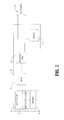
- Fig. 2 is a schematic block diagram of a generator algorithm according to the present disclosure
- Fig. 3 is a rear, perspective view of the end effector of Fig. 1 shown with tissue grasped therein;
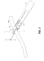
- Fig. 4 is a side, partial internal view of an endoscopic forceps according to the present disclosure
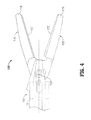
- Fig. 5 is a perspective view of an open bipolar forceps according to the present disclosure
- Figs. 6A and 6B shows a flow chart showing a sealing method using the endoscopic bipolar forceps according to the present disclosure
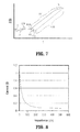
- Fig. 7 shows a graph illustrating the changes occurring in tissue impedance during sealing utilizing the method shown in Figs. 6A and 6B ;
- Fig. 8 shows a current v. impedance control curve according to the present disclosure.
- proximal refers to the end of the forceps 10 which is closer to the user
- distal refers to the end of the forceps which is further from the user
- the present disclosure provides for a system and method for sealing tissue.
- the method may be implemented as computer-readable instructions executed by a controller.
- an electrosurgical including a controller may execute the instructions.
- the generator includes an RF output stage configured to supply electrosurgical energy to tissue via at least one active electrode configured to apply electrosurgical energy to tissue, sensing circuitry configured to measure impedance of tissue, and a controller.
- the controller is configured to determine whether a tissue reaction has occurred as a function of a minimum impedance value and a predetermined rise in impedance, wherein tissue reaction corresponds to a boiling point of tissue fluid.
- the controller is further configured to generate a target impedance trajectory as a function of measured impedance and desired rate of change based on the tissue reaction determination, wherein the target impedance trajectory includes a plurality of target impedance values and drive tissue impedance along the target impedance trajectory by adjusting the output level of the electrosurgical generator to substantially match tissue impedance to a corresponding target impedance value for at least a predetermined minimum time period.
- Fig. 1 is a schematic illustration of an electrosurgical system 1.
- the system 1 includes an electrosurgical forceps 10 for treating patient tissue.
- Electrosurgical RF energy is supplied to the forceps 10 by a generator 2 via a cable 18 thus allowing the user to selectively coagulate and/or seal tissue.
- the forceps 10 is an endoscopic version of a vessel sealing bipolar forceps.
- the forceps 10 is configured to support an effector assembly 100 and generally includes a housing 20, a handle assembly 30, a rotating assembly 80, and a trigger assembly 70 that mutually cooperate with the end effector assembly 100 to grasp, seal and, if required, divide tissue.
- Forceps 10 also includes a shaft 12 that has a distal end 14 which mechanically engages the end effector assembly 100 and a proximal end 16 which mechanically engages the housing 20 proximate the rotating assembly 80.
- the forceps 10 also includes a plug (not shown) that connects the forceps 10 to a source of electrosurgical energy, e.g., generator 2, via cable 18.
- Handle assembly 30 includes a fixed handle 50 and a movable handle 40. Handle 40 moves relative to the fixed handle 50 to actuate the end effector assembly 100 and enable a user to selectively grasp and manipulate tissue 400 as shown in Fig. 3 .
- Forceps 10 may also include an identification module (not explicitly shown) such as a resistor or computer memory readable by the generator 2 to identify the forceps.
- end effector assembly 100 includes a pair of opposing jaw members 110 and 120 each having an electrically conductive sealing plate 112 and 122, respectively, attached thereto for conducting electrosurgical energy through tissue 400 held therebetween. More particularly, the jaw members 110 and 120 move in response to movement of handle 40 from an open position to a closed position. In open position the sealing plates 112 and 122 are disposed in spaced relation relative to one another. In a clamping or closed position the sealing plates 112 and 122 cooperate to grasp tissue and apply electrosurgical energy thereto.
- end effector assembly 100 includes a jaw angle sensor (now explicitly shown) that is adapted to sense the included angle 114 between opposing jaw members 110 and 120 and is configured to operably couple to generator 2.
- Jaw members 110 and 120 are activated using a drive assembly (not shown) enclosed within the housing 20.
- the drive assembly cooperates with the movable handle 40 to impart movement of the jaw members 110 and 120 from the open position to the clamping or closed position.
- Examples of handle assemblies are shown and described in commonly-owned U.S. Patent 7,156,846 entitled “VESSEL SEALER AND DIVIDER FOR USE WITH SMALL TROCARS AND CANNULAS" which is hereby incorporated by reference herein in their entirety.
- Jaw members 110 and 120 also include outer housings on insulators 116 and 126 which together with the dimension of the conductive plates of the jaw members 110 and 120 are configured to limit and/or reduce many of the known undesirable effects related to tissue sealing, e.g., flashover, thermal spread and stray current dissipation.
- the handle assembly 30 of the present disclosure may include a four-bar mechanical linkage which provides a unique mechanical advantage when sealing tissue between the jaw members 110 and 120.
- handle 40 may be compressed fully to lock the electrically conductive sealing plates 112 and 122 in a closed position against the tissue.
- the forceps 10 also includes a rotating assembly 80 mechanically associated with the shaft 12 and the drive assembly (not shown). Movement of the rotating assembly 80 imparts similar rotational movement to the shaft 12 which, in turn, rotates the end effector assembly 100.
- a rotating assembly 80 mechanically associated with the shaft 12 and the drive assembly (not shown). Movement of the rotating assembly 80 imparts similar rotational movement to the shaft 12 which, in turn, rotates the end effector assembly 100.
- end effector assembly 100 attaches to the distal end 14 of shaft 12.
- the jaw members 110 and 120 are pivotable about a pivot 160 from the open to closed positions upon relative reciprocation, i.e., longitudinal movement, of the drive assembly (not shown).
- mechanical and cooperative relationships with respect to the various moving elements of the end effector assembly 100 are further described by example with respect to the above-mentioned commonly-owned U.S. Patent 7,156,846 .
- the forceps 10 may be designed such that it is fully or partially disposable depending upon a particular purpose or to achieve a particular result.
- end effector assembly 100 may be selectively and releasably engageable with the distal end 14 of the shaft 12 and/or the proximal end 16 of the shaft 12 may be selectively and releasably engageable with the housing 20 and handle assembly 30.
- the forceps 10 may be either partially disposable or replaceable, such as where a new or different end effector assembly 100 or end effector assembly 100 and shaft 12 are used to selectively replace the old end effector assembly 100 as needed.
- the generator 2 includes input controls (e.g., buttons, activators, switches, touch screen, etc.) for controlling the generator 2.
- the generator 2 includes one or more display screens for providing the surgeon with variety of output information (e.g., intensity settings, treatment complete indicators, etc.).
- the controls allow the surgeon to adjust power of the RF energy, waveform, and other parameters to achieve the desired waveform suitable for a particular task (e.g., coagulating, tissue sealing, division with hemostatis, etc.).
- the forceps 10 may include a plurality of input controls which may be redundant with certain input controls of the generator 2. Placing the input controls at the forceps 10 allows for easier and faster modification of RF energy parameters during the surgical procedure without requiring interaction with the generator 2.
- Fig. 2 shows a schematic block diagram of the generator 2 having a controller 4, a high voltage DC power supply 7 ("HVPS"), an RF output stage 8, and a sensor circuitry 11.
- the DC power supply 7 provides DC power to an RF output stage 8 which then converts DC power into RF energy and delivers the RF energy to the forceps 10.
- the controller 4 includes a processor 5 operably connected to a memory 6 which may be volatile type memory (e.g., RAM) and/or non-volatile type memory (e.g., flash media, disk media, etc.).
- the processor 5 includes an output port which is operably connected to the HVPS 7 and/or RF output stage 8 allowing the processor 5 to control the output of the generator 2 according to either open and/or closed control loop schemes.
- a closed loop control scheme may be a feedback control loop wherein the sensor circuitry 11 provides feedback to the controller 4 (i.e., information obtained from one ore more of sensing mechanisms for sensing various tissue parameters such as tissue impedance, tissue temperature, fluid presence, output current and/or voltage, etc.).
- the controller 4 then signals the HVPS 7 and/or RF output stage 8 which then adjusts DC and/or RF power supply, respectively.
- the controller 4 also receives input signals from the input controls of the generator 2 and/or forceps 10.
- the controller 4 utilizes the input signals to adjust the power output of the generator 2 and/or instructs the generator 2 to perform other control functions.
- sealing of the tissue 400 is accomplished by virtue of a unique combination of gap control, pressure and electrical control.
- controlling the intensity, frequency and duration of the electrosurgical energy applied to the tissue through the sealing plate 112 and 122 are important electrical considerations for sealing tissue.
- two mechanical factors play an important role in determining the resulting thickness of the sealed tissue and the effectiveness of the seal, i.e., the pressure applied between the opposing jaw members 110 and 120 (between about 3 kg/cm2 to about 16kg/cm2) and the gap distance "G" between the opposing sealing plates 112 and 122 of the jaw members 110 and 120, respectively, during the sealing process (between about 0.001 inches to about 0.006 inches).
- One or more stop members 90 may be employed on one or both sealing plates to control the gap distance.
- a third mechanical factor has recently been determined to contribute to the quality and consistency of a tissue seal, namely the closure rate of the electrically conductive surfaces or sealing plates during electrical activation.
- each of the jaw members 110 and 120 includes a pair of electrically conductive sealing plates 112, 122, respectively, disposed on an inner-facing surface thereof.
- the forceps 10 is now ready for selective application of electrosurgical energy as shown in Fig. 4 .
- the electrically conductive sealing plates 112 and 122 cooperate to seal tissue 400 held therebetween upon the application of electrosurgical energy.
- the system 1 regulates application of energy and pressure to achieve an effective seal capable of withstanding high burst pressures.
- the generator 2 applies energy to tissue at constant current based on the current control curve of Fig. 8 which is discussed in more detail below.
- Energy application is regulated by the controller 4 pursuant to an algorithm stored within the memory 6.
- the algorithm maintains energy supplied to the tissue at constant voltage.
- the algorithm varies output based on the type of tissue being sealed. For instance, thicker tissue typically requires more power, whereas thinner tissue requires less power. Therefore, the algorithm adjusts the output based on tissue type by modifying specific variables (e.g., voltage being maintained, duration of power application etc.). In embodiments, the algorithm adjusts the output based on jaw angle.
- the forceps 10 may be configured to include a ratchet mechanism (not explicitly shown) which initially locks the jaw members 110 and 120 against the tissue under a desired tissue pressure and then increases the pressure according to the command from the processor 5 to an optimum tissue pressure.
- the ratchet mechanism (not explicitly shown) is configured to adjust the pressure based on electrical activation and/or the tissue reaction.
- the pressure may be controlled in a similar manner towards the end of the seal cycle, i.e., release pressure.
- the pressure may be held constant or varied during a cooling period.
- a similar or the same ratchet mechanism may be employed for this purpose as well.
- the ratchet mechanism (not explicitly shown) may be configured to automatically release or unlock at the end of a cooling period.
- Other controllable closure mechanisms or pressure-applying mechanism are also envisioned which may be associated with the handle assembly 30, the housing 20 and/or the jaw members 110 and 120. Any of these mechanisms may be housed in the housing 20 or form a part of each particular structure.
- the ratchet, closure, and/or pressure-applying mechanism may include any suitable actuating device, for example without limitation, a solenoid, stepper motor, vacuum actuator, and/or a pressure actuator.
- One or more stop members 90 may be selectively controllable to regulate the closure pressure and gap distance to affect the seal.
- Commonly-owned U.S. Patent No. 7,491,201 describes one such variable stop system which may be used for this purpose, the entire contents being incorporated by reference herein.
- the forceps 700 includes an end effector assembly 600 which is attached to the distal ends 516a and 516b of shafts 512a and 512b, respectively.
- the end effector assembly 600 includes a pair of opposing jaw members 610 and 620 which are pivotally connected about a pivot pin 665 and which are movable relative to one another to grasp vessels and/or tissue.
- Each of the opposing jaw members 610, 620 includes electrically sealing plates 112, 122 which allow the open forceps 700 to be used for clamping tissue for sealing.
- Each shaft 512a and 512b includes a handle 515 and 517, respectively, disposed at the proximal end 514a and 514b thereof which each define a finger hole 515a and 517a, respectively, therethrough for receiving a finger of the user.
- Finger holes 515a and 517a facilitate movement of the shafts 512a and 512b relative to one another which, in turn, pivot the jaw members 610 and 620 from an open position wherein the jaw members 610 and 620 are disposed in spaced relation relative to one another to a clamping or closed position wherein the jaw members 610 and 620 cooperate to grasp tissue or vessels therebetween.
- Further details relating to one particular open forceps are disclosed in commonly-owned U.S. Patent No. 7,811,283 entitled "OPEN VESSEL SEALING INSTRUMENT WITH CUTTING MECHANISM AND DISTAL LOCKOUT", the entire contents of which being incorporated by reference herein.
- Fig. 7 shows a graph illustrating the changes to tissue impedance when tissue is sealed utilizing the method of Figs. 6A-6B .
- the method is embodied in a software-based algorithm which is stored in memory 6 and is executed by processor 5.
- the vessel sealing procedure is activated (e.g., by pressing of a foot pedal or handswitch) and a host processor (e.g., processor 5) activates a vessel sealing algorithm and loads a configuration file.
- the configuration file may include a variety of variables which control the algorithm, e.g., end impedance threshold (EndZ), baseline cooling time (Base_Cool_T), and forceps/instrument identification (ForcepsID). Certain variables of the configuration file may be adjusted based on the instrument being used and the bar settings selected by a surgeon.
- a configuration file may be loaded from a data store included within controller 4. Additionally or alternatively, a configuration file may be loaded from a data store included within forceps 10.
- a plurality of configuration files may be included within controller 4.
- a configuration file may be selected and loaded by the algorithm in accordance with the type of forceps being utilized, e.g., the ForcepsID.
- forceps 10 are interrogated by controller 4 to ascertain ForcepsID, whereupon a configuration file corresponding to ForcepsID is loaded.
- Base_Cool_T may be determined in accordance with ForcepsID.
- step 304 the algorithm begins with an impedance sense phase, shown as phase I in Fig. 7 , during which the algorithm senses the tissue impedance with an interrogatory impedance sensing pulse of approximately 100 ms duration.
- the measured value of tissue impedance is stored as a variable DZDT_Start_Z.
- Tissue impedance is determined without appreciably changing the tissue.
- An adaptive cooling time (Adaptive_Cool_T) may be determined by adjusting the value indicated by Base_Cool_T in accordance with tissue impedance (DZDT_Start_Z). The cool-down time may be adjusted in accordance with additional or alternative factors as will be further described herein.
- E_Total The cumulative (i.e., net amount) of energy delivered to the tissue during the sealing procedure may be stored in a variable (E_Total).
- E_Total may be determined in any suitable manner, for example without limitation, by integrating the output power over the power delivery time. In embodiments, the output power is sampled and totaled on a periodic basis to yield an approximation of total energy delivery.
- Processor 5 may be configured to execute an interrupt service routine (ISR) that is programmed to periodically sense and total cumulative output power (E_Eotal). Variables corresponding to the maximum energy delivery rate (E_Max), minimum energy delivery rate (E_Min), and an average energy delivery rate (E_Avg) may additionally or alternatively sensed and/or computed and stored.
- ISR interrupt service routine
- Thermal properties related to the tissue may be sensed, recorded and/or computed during the sealing process. Such properties may include, without limitation, total thermal energy sensed, which may be expressed as the sensed temperature integrated over the time of the procedure (T_total), maximum tissue temperature (T_Max), minimum tissue temperature (T_Min), and average tissue temperature (T_Avg). Fluid properties, i.e., a total quantity of fluid, which may be expressed as the sensed quantity of fluid integrated over the time of the procedure (F_Total), a maximum fluid quantity (F_Max), a minimum fluid quantity (F_Min), and an average fluid quantity of fluid (F_Avg), may additionally or alternatively be sensed, recorded and/or computed.
- the algorithm in step 306 also monitors the phase between voltage and current. In embodiments, the phase is monitored continually during the procedure. The measured phase between voltage and current is compared to lower and upper phase thresholds.
- the lower phase threshold may be from about 0.25 to about -1.6, in embodiments from about 0.1 to about -1.5.
- the upper phase threshold may be from about 1.1 to about 1.6, in embodiments, from about 1.25 to about 1.5. If the measured phase is above the upper threshold, the algorithm detects an open circuit. If the measured phase is below the lower threshold, the algorithm detects a short circuit.
- step 306 If in step 306 a short circuit is detected, e.g., impedance is below a low impedance threshold and/or phase is above the upper threshold or if a an open circuit is detected, e.g., impedance is above a high impedance threshold and/or the phase is below the lower threshold, the algorithm in step 364 issues a regrasp alarm, and the algorithm exits in step 308. If, otherwise, no fault is detected in step 306 (i.e., no short and no open circuit detected), the algorithm starts the cook phase in step 310. The generator 2 then generates the pre-programmed ramping of current in its outer-loop and constant current per current curve within its inner-loop according to the current control curve shown in Fig. 8 .
- the curve of Fig. 8 may be modified by intensity settings.
- selecting a specific intensity setting e.g., low, medium, high, etc.
- selects a corresponding value, represented by a variable, Cook_AmpMult which then multiplies the curve.
- the Cook_AmpMult variable is specified in the configuration file and may range from about 2 Amps to about 5.5 Amps in some embodiments. In other embodiments, the Cook_AmpMult variable may range from about 2 Amps to about 8 Amps.
- the control curve for this algorithm is designed as a current curve which decreases rapidly from low impedances to high, although it could also be represented as a power or voltage curve.
- the control curve is designed ideally to reduce power with increasing impedances higher than approximately 24 ohms. This shape provides several advantages: 1) this curve allows high power with low impedance tissues, which allows the tissue to heat rapidly at the start of the seal cycle; 2) this shape tames the positive feedback caused by increase in delivered power as a result of increasing impedance 3) the curve allows a slower control system for Z control as the output power is reduced as the impedance rises, thus keeping the tissue impedance from rising too quickly.
- step 310 the algorithm initiates application of the RF energy by delivering current linearly over time to heat the tissue.
- RF energy may be delivered in a non-linear or in a time-independent step manner from zero to an "on" state. Delivery may be controlled through other parameters such as voltage and/or power and/or energy.
- the ramping of energy continues until one of two events occurs: 1) the maximum allowable value is reached or 2) the tissue "reacts.”
- tissue reaction is a point at which intracellular and/or extra-cellular fluid begins to boil and/or vaporize, resulting in an increase in tissue impedance.
- the maximum value is maintained until the tissue "reacts.” In the event that the tissue reacts prior to reaching the maximum value, the energy required to initiate a tissue "reaction" has been attained and the algorithm moves to an impedance control state.
- the first consideration is the minimum tissue impedance obtained during the heating period.
- the algorithm continuously monitors the tissue impedance after the onset of energy to identify the lowest value reached and then in step 314 stores this value as the variable ZLow. As time progresses throughout the entire energy activation cycle, the stored value is updated anytime a new value is read that is lower than the previous Zlow, represented by phase II in Fig. 7 .
- the generator 2 waits for the tissue impedance to drop.
- the generator 2 also captures EndZ_Offset impedance, which corresponds to the initial measured tissue impedance.
- the EndZ_Offset impedance is used to determine the threshold for terminating the procedure.
- EndZ_Offset impedance is measured approximately 100 ms after initial application of electrosurgical energy, which occurs approximately during phase I.
- the second consideration in identifying tissue reaction is a predetermined rise in impedance. This is represented by the variable Z_Rise, which is loaded from the configuration file and can range from about 1 ohm to about 750 ohms.
- the algorithm waits for a predetermined period of time to identify whether a rise in impedance has occurred, represented by phases IIIa and IIIb in Fig. 7 .
- the algorithm repeatedly attempts to identify a tissue reaction by determining if Z(t) > ZLow + Z_Rise where Z(t) is the impedance at any time during sampling.
- the algorithm verifies whether the timer for waiting for impedance to rise has expired.
- the generator 2 issues a regrasp alarm due to the tissue not responding.
- the generator 2 verifies whether the procedure is complete by comparing measured impedance to the impedance threshold. If the measured impedance is greater than the impedance threshold, the tissue is sealed and the electrosurgical energy (e.g., RF power) is shut off and the algorithm proceeds to step 360 wherein the cooling timer is activated.
- the electrosurgical energy e.g., RF power
- the actual cooling time (Adaptive_Cool_T) is determined in accordance with the initial impedance (DZDT_Start_Z), final impedance (DZDT_End_Z), the instrument type (Forceps_ID), energy delivered to the tissue (i.e., E_total, E_Max, E_Min and/or E_Avg), thermal properties (i.e., T_total, T_Max, T_Min and/or T_Avg), and/or fluid properties (i.e., F_total, F_Max, F_Min and/or F_Avg).
- Actual cooling time may range from about zero seconds to about ten seconds.
- the actual cooling time may range from about a half a second to about two seconds.
- Adaptive_Cool_T is initially set to Base_Cool_T.
- Adaptive_Cool_T may then be increased or decreased in accordance with biologic or operational parameters. For example without limitation, Adaptive_Cool_T may be increased by an amount correlated to the extent by which a parameter exceeds a parameter threshold, and, conversely, Adaptive_Cool_T may be decreased by an amount correlated to the extent by which a parameter falls short of a parameter threshold. In embodiments, Adaptive_Cool_T may only be increased, or only decreased.
- a parameter may cause an increase in Adaptive_Cool_T
- a parameters may cause a decrease in Adaptive_Cool_T
- a parameter may cause both and increase and a decrease in Adaptive_Cool_T.
- step 328 which prevents sealing tissue that has already been sealed.
- step 326 the generator determines whether the measured impedance is below the impedance threshold, and if so then the generator 2 issues a regrasp alarm in step 364 and exits in step 308.
- the algorithm has a hysteresis identifier (Z_HIST) defined by a specified drop in impedance occurring in under a specified duration in time. This is used to filter out the noise which may be mistaken by the algorithm for the actual rise in impedance.
- Z_HIST hysteresis identifier
- the algorithm determines whether the measured impedance is less than the rise in impedance above the lowest impedance minus the hysteresis identifier (i.e., Z(t) ⁇ Zlow + Z_Rise - Z_Hist). Step 325 is repeated for a specified period of time by determining whether a timer has expired in step 322 (Z_Hist tmr), the repetition of the loop is determined in step 327.
- the system After the tissue reacts and tissue impedance begins to rise, if the impedance drops below a hysteresis value within an allotted time, the system identifies the event "not stable" as shown in phase IIIa. The algorithm also begins looking for the next rise in impedance by determining if the measured impedance is greater than the specified level of impedance, defined by the equation Z(t) ⁇ Zlow + Z_Rise - Z_Hist. If the timer expires and the impedance has not dropped below the hysteresis value, the reaction is considered stable and the impedance control state is implemented.
- the algorithm calculates the desired impedance trajectory based on the actual impedance and the desired rate of change in step 330.
- the algorithm calculates a target impedance value for the control system at each time-step, based on a predefined desired rate of change of impedance (dZ/dt), represented as phase IV in Fig. 7 .
- the desired rate of change may be stored as a variable and be loaded during the step 302.
- the control system attempts to adjust the tissue impedance to match the target impedance.
- the target impedance takes the form of a target trajectory with the initial impedance value and time taken when the tissue reaction is considered real and stable.
- the trajectory could take a non-linear and/or quasi-linear form.
- the algorithm calculates a Z trajectory based on the actual impedance and desired dZ/dt, i.e., a rate of rise of impedance over time, selected manually or automatically based on tissue type determined by the selected instrument.
- the target impedance trajectory includes a plurality of a target impedance values at each time step.
- the algorithm drives tissue impedance along the target impedance trajectory by adjusting the power output level to substantially match tissue impedance to a corresponding target impedance value. While the algorithm continues to direct the RF energy to drive the tissue impedance to match the specified trajectory, the algorithm monitors the impedance to make the appropriate corrections. The algorithm determines whether tissue fusion is complete and the system should cease RF energy in phase V as shown in Fig. 7 . This is determined by monitoring the actual measured impedance rising above a predetermined threshold and staying above the threshold for a predetermined period of time.
- the threshold is defined as a specified level, EndZ, above the initial impedance value, EndZ_Offset. This determination minimizes the likelihood of terminating electrosurgical energy early when the tissue is not properly or completely sealed.
- step 334 it is determined if the measured impedance is greater than as the specified level of impedance above the initial impedance value (i.e., Z(t) > EndZ + EndZ_Offset), if yes, the algorithm verifies whether this state is maintained for the given time.
- the algorithm initializes the timer, DZDT_ENDZ_TIMER.
- the algorithm performs the determination of step 334 for the duration of the timer DZDT_ENDZ_TIMER, which may be about 400ms, the expiration of which is verified in step 340.
- the algorithm exits with an alarm. This alerts the user to a possible unfused tissue condition or unreliable seal.
- a predetermined time period e.g., maximum seal timer
- EndZ_Offset is the tissue impedance approximately about 100ms after the onset of RF energy.
- the time duration for a cycle shut-off condition to verify tissue fusion has occurred (i.e., the value of DZDT_ENDZ_TIMER) may range from 0 seconds to 2 seconds.
- the value of the EndZ_Offset could be calculated from a variety of different methods and utilizing a variety of different parameters such as the starting tissue impedance, the minimum impedance, the impedance at maximum current or minimum voltage, the impedance at either a positive or negative slope change of impedance, and/or a constant value specified within the programming or by the end user.
- EndZ_TRAJ_LIMIT a predetermined value
- the ENDZ_TRAJ_LIMIT ranges from about 1 ohm to about 500 ohms.
- the algorithm determines whether the measured impedance is below ENDZ_TRAJ_LIMIT. This event aids in mitigating the occurrences of the algorithm exiting while the tissue is not fused.
- step 355 the algorithm determines whether the time spent within step 332, the start of application of RF energy to match tissue impedance to a desired impedance trajectory energy, is above a predetermined time period. This ensures that sufficient time has expired during which RF energy was applied to tissue in accordance with the above-described trajectory-matching treatment profile.
- the algorithm may store the minimum time for energy application as a variable, MIN_DZDT_TMR, which may be from about 100 ms to about 5000 ms, in embodiments, from about 150 ms to about 1000 ms.
- the algorithm also includes a timer variable which stores the elapsed time from step 330 as a variable, DZDT_TMR. The timer represents the total time the algorithm dwelt in step 332.
- step 355 the algorithm compares the DZDT_TMR to MIN_DZDT_TMR. If the elapsed time exceeds the minimum threshold the algorithm spent during its impedance matching phase, namely phases IV and V, then the algorithm proceeds to step 360 or directly step 328, indicating that a sufficient amount of time was spent supplying RF energy to tissue. If the elapsed time is lower than the minimum time, then the algorithm proceeds to step 364, which issues a regrasp alarm. This timer ensures that the algorithm spends a sufficient amount of time during the phases IV and V and/or VII and VIII of the treatment cycle.
- step 360 the algorithm goes into a wait state having a duration in accordance with Adaptive_Cool_T to enable the fused tissue to set.
- a seal complete signal which may be an audio indication (i.e., an "endtone" and/or a visual indication, and in the step 328 the algorithm exits.
- the algorithm Prior to proceeding to step 334 to determine if the seal process is complete, the algorithm performs a plurality of error checks. In particular, the algorithm determines whether excessive fluid has entered the field or an object has been encountered that causes the impedance to drop unexpectedly to affect the ongoing tissue reaction. This event is identified by a negative deviation between the target impedance and tissue impedance (i.e. tissue impedance is less than target impedance) as represented by phase VI in Fig. 7 . Therefore, to identify that this event has occurred and is real (e.g., not an arcing event) several conditions are verified.
- tissue impedance i.e. tissue impedance is less than target impedance
- a reset threshold value RstLim
- step 346 at the onset of successfully meeting both of these conditions, the algorithm begins a timer, DZDT_ZTRAJ_RST_TMR, to define if the deviation event is true and stable or false and transient.
- step 348 the algorithm determines whether the measured impedance is above the reset threshold value, RstLim, above the lowest impedance reached, ZLow plus a hysteresis value, ZHist. If this condition is satisfied before the timer DZDT_ZTRAJ_RST_TMR expires in step 350, the event is considered transient and the algorithm continues to direct the electrosurgical energy to cause the tissue impedance to follow the previous trajectory by returning to step 332.
- step 352 the algorithm adjusts to look for tissue reaction as described earlier with respect to step 318.
- the impedance is monitored to identify a rise above the minimum value, Zlow, and once this occurs as represented by phase VII in Fig. 7 , the trajectory is recalculated to begin at the new reaction impedance and the trajectory time is reset by returning to step 332 as represented by phase VIII in Fig. 7 .
- the algorithm then continues with the same series of events described previously until tissue fusion is identified. If a rise in impedance is not detected in step 354 within a predetermined period of time then the algorithm proceeds to step 364 in which the algorithm issues a regrasp alarm, and in the step 308 the process concludes.
- the algorithm directs the RF energy to maintain a match between the tissue impedance and the target value throughout time.
- the target trajectory is incremented in a normal fashion during all events unless a reset trajectory is requested.
- the trajectory could enter a holding pattern with respect to the last value at any event when the actual tissue impedance deviates significantly from the target impedance until either a reset condition is requested or the tissue impedance realigns with the target value.
- the logic intent is to identify an event that results in notable and significant deviation from the impedance target by the tissue and thereby justifying a new target trajectory. Initializing a new trajectory results in mitigating excessive energy delivery to the tissue as the impedance deviates from the target and therefore prevents an uncontrollable tissue effect once the tissue re-reacts.
- the algorithm will exit with an alarm. This alerts the user to a possible attempt to seal tissue which is already desiccated or sealed, an attempt to seal tissue which is so large that the tissue is not sufficiently affected by the RF energy delivered, an attempt to seal non-tissue, or a persistent short circuit during the sealing process.
- the algorithm according to the present disclosure allows for the slow desiccation of tissue and for collagen to denature in a slow controllable fashion. As desiccation progresses, the resulting seal gains plastic-like qualities, becoming hard and clear, which makes the seal capable of withstanding higher burst pressures.
Abstract
Description
- The present disclosure relates to an electrosurgical system and method for performing electrosurgical procedures. More particularly, the present disclosure relates to sealing tissue, wherein energy is administered to match measured impedance to a desired impedance, and a tissue cooling time is observed prior to the completion of the seal.
- Electrosurgery involves application of high radio frequency electrical current to a surgical site to cut, ablate, or coagulate tissue. In monopolar electrosurgery, a source or active electrode delivers radio frequency energy from the electrosurgical generator to the tissue and a return electrode (e.g., a return pad) carries the current back to the generator. In monopolar electrosurgery, the source electrode is typically part of the surgical instrument held by the surgeon and applied to the tissue to be treated. The patient return electrode is placed remotely from the active electrode to carry the current back to the generator.
- In bipolar electrosurgery, one of the electrodes of the hand-held instrument functions as the active electrode and the other as the return electrode. The return electrode is placed in close proximity to the active electrode such that an electrical circuit is formed between the two electrodes (e.g., electrosurgical forceps). In this manner, the applied electrical current is limited to the body tissue positioned between the electrodes. When the electrodes are sufficiently separated from one another, the electrical circuit is open and thus inadvertent contact of body tissue with either of the separated electrodes does not cause current to flow.
- Bipolar electrosurgery generally involves the use of forceps. A forceps is a pliers-like instrument which relies on mechanical action between its jaws to grasp, clamp and constrict vessels or tissue. So-called "open forceps" are commonly used in open surgical procedures whereas "endoscopic forceps" or "laparoscopic forceps" are, as the name implies, used for less invasive endoscopic surgical procedures. Electrosurgical forceps (open or endoscopic) utilize mechanical clamping action and electrical energy to effect hemostasis on the clamped tissue. The forceps include electrosurgically conductive plates which apply electrosurgical energy to the clamped tissue. By controlling the intensity, frequency and duration of the electrosurgical energy applied through the conductive plates to the tissue, the surgeon can coagulate, cauterize and/or seal tissue.
- Tissue or vessel sealing is a process of liquefying the collagen, elastin and ground substances in the tissue so that they reform into a fused mass with significantly-reduced demarcation between the opposing tissue structures. Cauterization involves the use of heat to destroy tissue and coagulation is a process of desiccating tissue wherein the tissue cells are ruptured and dried.
- Tissue sealing procedures involve more than simply cauterizing or coagulating tissue to create an effective seal; the procedures involve precise control of a variety of factors. For example, in order to affect a proper seal in vessels or tissue, it has been determined that two predominant mechanical parameters must be accurately controlled: the pressure applied to the tissue; and the gap distance between the electrodes (i.e., distance between opposing jaw members or opposing sealing plates). In addition, electrosurgical energy must be applied to the tissue under controlled conditions to ensure creation of an effective vessel seal. Techniques have been developed whereby the energy applied to the tissue is varied during the tissue sealing process to achieve a desired tissue impedance trajectory. When a target tissue impedance threshold is reached, the tissue seal is deemed completed and the delivery of electrosurgical energy is halted.
- The present disclosure relates to a vessel or tissue sealing system and method. In particular, the system discloses an electrosurgical instrument, which may be a bipolar forceps having two jaw members configured for grasping tissue. Each of the jaw members may include a sealing plate which communicates electrosurgical energy to the tissue. At the start of the procedure, the system may transmit an initial interrogatory pulse for determining initial tissue impedance. Additionally or alternatively at the start of the procedure, the system may identify characteristics of the electrosurgical instrument. The system determines whether tissue reaction has occurred and calculates the desired impedance trajectory. The system calculates a target impedance value at each time step based on a predefined desired rate of change of impedance. The system then controls measured tissue impedance to match target impedance. The system may sense parameters related to the sealing process. For example without limitation, the system may sense a temperature, a tissue type, and/or a fluid type. Additionally or alternatively, the system may determine an aggregate amount of energy delivered during the sealing process. The delivery of energy may be halted when the measured impedance is above threshold for a predetermined period of time. The threshold is defined as a specified impedance level above the initial measured impedance value.
- According to one aspect of the present disclosure, an electrosurgical system is disclosed. The electrosurgical system includes an electrosurgical generator adapted to supply electrosurgical energy to tissue. The electrosurgical generator may include impedance sensing circuitry which measures impedance of tissue, a processor configured to determine whether a tissue reaction has occurred as a function of a minimum impedance value and a predetermined rise in impedance, wherein tissue reaction corresponds to a boiling point of tissue fluid, and an electrosurgical instrument including at least one active electrode adapted to apply electrosurgical energy to tissue. The electrosurgical generator may include temperature sensing circuitry and/or fluid sensing circuitry. Additionally or alternatively, the electrosurgical generator may include circuitry for identifying characteristics of an electrosurgical instrument coupled thereto. The electrosurgical instrument may include an identification module to enable the electrosurgical generator to identify the instrument. For example without limitation, the identification module may include at least one resistive element have a resistance value corresponding to a characteristic of the instrument, such as the instrument configuration (i.e., model number), a unique instrument identifier (i.e., serial number) and/or a thermal property of the jaws. In embodiments, the identification module may include computer memory (i.e., read-only memory or flash memory), RFID tag, optical tag (i.e., barcode), or other encoding as will be familiar to the skilled artisan. In embodiments, the instrument includes a sensor in operable communication with the generator that is configured to sense the included angle between the jaws, which angle may be indicative of the size and/or mass of tissue held therebetween. The generator may use an algorithm or a lookup table to determine a desired cool-down time based upon the identification module.
- According to one aspect of the present disclosure, an electrosurgical generator is disclosed. The generator includes an RF output stage configured to supply electrosurgical energy to tissue via at least one active electrode configured to apply electrosurgical energy to tissue; sensing circuitry configured to measure impedance of tissue; and a controller. The controller is configured to determine whether a tissue reaction has occurred as a function of a minimum impedance value and a predetermined rise in impedance, wherein tissue reaction corresponds to a boiling point of tissue fluid; generate a target impedance trajectory as a function of measured impedance and desired rate of change based on the tissue reaction determination, wherein the target impedance trajectory includes a plurality of target impedance values; and drive tissue impedance along the target impedance trajectory by adjusting the output level of the electrosurgical generator to substantially match tissue impedance to a corresponding target impedance value for at least a predetermined minimum time period.
- Additionally or alternatively, the sensing circuit is further configured to measure phase between voltage and current waveforms of the electrosurgical energy delivered to the tissue.
- According to another aspect of the present disclosure, an electrosurgical generator is disclosed. The generator includes an RF output stage configured to supply electrosurgical energy to tissue; sensing circuitry configured to measure impedance of tissue and phase between voltage and current waveforms of the electrosurgical energy delivered to the tissue; and a controller. The controller is configured to determine whether tissue reaction has occurred as a function of a minimum impedance value and a predetermined rise in impedance, wherein tissue reaction corresponds to a boiling point of tissue fluid; generate a target impedance trajectory as a function of measured impedance and desired rate of change based on the tissue reaction determination, wherein the target impedance trajectory includes a plurality of target impedance values; and drive tissue impedance along the target impedance trajectory by adjusting the output level of the electrosurgical generator to substantially match tissue impedance to a corresponding target impedance value for at least a predetermined minimum time period. The generator further includes an electrosurgical instrument including at least one active electrode configured to apply electrosurgical energy to tissue.
- Additionally or alternatively, the controller is further configured to terminate delivery of electrosurgical energy in response to the phase being outside lower and upper phase thresholds.
- Additionally or alternatively, the controller is further configured to measure time for driving tissue impedance along the target impedance trajectory and comparing the measured time to the predetermined minimum time period.
- Additionally or alternatively, the controller is configured to output at least one of an alarm, e.g. a regrasp tissue alarm, or a signal to adjust output of the RF output stage in response to the measured time being less than the predetermined minimum time period.
- Additionally or alternatively, the controller is configured to generate a threshold impedance value as a function of an offset impedance value and an ending impedance value, wherein the offset impedance value is obtained after an initial impedance measurement.
- Additionally or alternatively, the controller is configured to determine whether tissue impedance is at least equal to the threshold impedance for a predetermined shutoff period.
- Additionally or alternatively, the controller is configured to adjust output of the electrosurgical generator in response to the determination whether tissue impedance is at least equal to the threshold impedance for a predetermined shutoff period.
- Additionally or alternatively, the controller is configured to determine whether tissue is sealed and, if so, to terminate delivery of electrosurgical energy and thereafter activate a cooling timer, wherein the controller is configured to output a signal indicating expiry of a cooling period, wherein pressure is applied to tissue between vessel sealing jaw members of a/the electrosurgical instrument during the cooling period.
- A method for performing an electrosurgical procedure is also contemplated by the present disclosure. The method includes: applying electrosurgical energy at an output level to tissue from an electrosurgical generator; determining whether tissue reaction has occurred as a function of a minimum impedance value and a predetermined rise in impedance, wherein tissue reaction corresponds to a boiling point of tissue fluid; generating a target impedance trajectory as a function of measured impedance and desired rate of change based on the tissue reaction determination, the target impedance trajectory including a plurality of target impedance values; and driving tissue impedance along the target impedance trajectory by adjusting the output level to substantially match tissue impedance to a corresponding target impedance value for at least a predetermined minimum time period.
- Additionally or alternatively, measuring phase between voltage and current waveforms of the electrosurgical energy delivered to the tissue.
- Additionally or alternatively, terminating delivery of electrosurgical energy in response to the phase being outside lower and upper phase thresholds.
- Additionally or alternatively, measuring time for driving tissue impedance along the target impedance trajectory and comparing the measured time to the predetermined minimum time period.
- Additionally or alternatively, outputting at least one of an alarm or a signal to adjust output of the RF output stage in response to the measured time being less than the predetermined minimum time period.
- The above and other aspects, features, and advantages of the present disclosure will become more apparent in light of the following detailed description when taken in conjunction with the accompanying drawings wherein:
-
Fig. 1 is a perspective view of one embodiment of an electrosurgical system according to the present disclosure; -
Fig. 2 is a schematic block diagram of a generator algorithm according to the present disclosure; -
Fig. 3 is a rear, perspective view of the end effector ofFig. 1 shown with tissue grasped therein; -
Fig. 4 is a side, partial internal view of an endoscopic forceps according to the present disclosure; -
Fig. 5 is a perspective view of an open bipolar forceps according to the present disclosure; -
Figs. 6A and6B shows a flow chart showing a sealing method using the endoscopic bipolar forceps according to the present disclosure; -
Fig. 7 shows a graph illustrating the changes occurring in tissue impedance during sealing utilizing the method shown inFigs. 6A and6B ; and -
Fig. 8 shows a current v. impedance control curve according to the present disclosure. - Particular embodiments of the present disclosure will be described hereinbelow with reference to the accompanying drawings. In the following description, well-known functions or constructions are not described in detail to avoid obscuring the present disclosure in unnecessary detail. Those skilled in the art will understand that the present disclosure may be adapted for use with either an endoscopic instrument, laparoscopic instrument, or an open instrument. It should also be appreciated that different electrical and mechanical connections and other considerations may apply to each particular type of instrument, however, the novel aspects with respect to vessel and tissue sealing are generally consistent with respect to both the open or endoscopic designs.
- In the drawings and in the description which follows, the term "proximal" refers to the end of the
forceps 10 which is closer to the user, while the term "distal" refers to the end of the forceps which is further from the user. - The present disclosure provides for a system and method for sealing tissue. The method may be implemented as computer-readable instructions executed by a controller. In embodiments, an electrosurgical including a controller may execute the instructions. The generator includes an RF output stage configured to supply electrosurgical energy to tissue via at least one active electrode configured to apply electrosurgical energy to tissue, sensing circuitry configured to measure impedance of tissue, and a controller. The controller is configured to determine whether a tissue reaction has occurred as a function of a minimum impedance value and a predetermined rise in impedance, wherein tissue reaction corresponds to a boiling point of tissue fluid. The controller is further configured to generate a target impedance trajectory as a function of measured impedance and desired rate of change based on the tissue reaction determination, wherein the target impedance trajectory includes a plurality of target impedance values and drive tissue impedance along the target impedance trajectory by adjusting the output level of the electrosurgical generator to substantially match tissue impedance to a corresponding target impedance value for at least a predetermined minimum time period.
-
Fig. 1 is a schematic illustration of anelectrosurgical system 1. Thesystem 1 includes anelectrosurgical forceps 10 for treating patient tissue. Electrosurgical RF energy is supplied to theforceps 10 by agenerator 2 via acable 18 thus allowing the user to selectively coagulate and/or seal tissue. - As shown in
Fig. 1 , theforceps 10 is an endoscopic version of a vessel sealing bipolar forceps. Theforceps 10 is configured to support aneffector assembly 100 and generally includes ahousing 20, ahandle assembly 30, a rotatingassembly 80, and atrigger assembly 70 that mutually cooperate with theend effector assembly 100 to grasp, seal and, if required, divide tissue.Forceps 10 also includes ashaft 12 that has adistal end 14 which mechanically engages theend effector assembly 100 and aproximal end 16 which mechanically engages thehousing 20 proximate the rotatingassembly 80. - The
forceps 10 also includes a plug (not shown) that connects theforceps 10 to a source of electrosurgical energy, e.g.,generator 2, viacable 18. Handleassembly 30 includes a fixedhandle 50 and amovable handle 40.Handle 40 moves relative to the fixedhandle 50 to actuate theend effector assembly 100 and enable a user to selectively grasp and manipulatetissue 400 as shown inFig. 3 .Forceps 10 may also include an identification module (not explicitly shown) such as a resistor or computer memory readable by thegenerator 2 to identify the forceps. - Referring to
Figs. 1 ,3 and4 ,end effector assembly 100 includes a pair of opposingjaw members conductive sealing plate tissue 400 held therebetween. More particularly, thejaw members handle 40 from an open position to a closed position. In open position the sealingplates plates end effector assembly 100 includes a jaw angle sensor (now explicitly shown) that is adapted to sense the includedangle 114 between opposingjaw members generator 2. -
Jaw members housing 20. The drive assembly cooperates with themovable handle 40 to impart movement of thejaw members U.S. Patent 7,156,846 entitled "VESSEL SEALER AND DIVIDER FOR USE WITH SMALL TROCARS AND CANNULAS" which is hereby incorporated by reference herein in their entirety. -
Jaw members insulators jaw members - In addition, the
handle assembly 30 of the present disclosure may include a four-bar mechanical linkage which provides a unique mechanical advantage when sealing tissue between thejaw members jaw members conductive sealing plates forceps 10 are disclosed in the above-cited commonly-ownedU.S. Patent 7,156,846 , which discloses an off-axis, lever-like handle assembly. - The
forceps 10 also includes a rotatingassembly 80 mechanically associated with theshaft 12 and the drive assembly (not shown). Movement of the rotatingassembly 80 imparts similar rotational movement to theshaft 12 which, in turn, rotates theend effector assembly 100. Various features along with various electrical configurations for the transference of electrosurgical energy through thehandle assembly 20 and the rotatingassembly 80 are described in more detail in the above-mentioned commonly-ownedU.S. Patent 7,156,846 . - As best seen with respect to
Figs. 1 and4 ,end effector assembly 100 attaches to thedistal end 14 ofshaft 12. Thejaw members pivot 160 from the open to closed positions upon relative reciprocation, i.e., longitudinal movement, of the drive assembly (not shown). Again, mechanical and cooperative relationships with respect to the various moving elements of theend effector assembly 100 are further described by example with respect to the above-mentioned commonly-ownedU.S. Patent 7,156,846 . - The
forceps 10 may be designed such that it is fully or partially disposable depending upon a particular purpose or to achieve a particular result. For example,end effector assembly 100 may be selectively and releasably engageable with thedistal end 14 of theshaft 12 and/or theproximal end 16 of theshaft 12 may be selectively and releasably engageable with thehousing 20 and handleassembly 30. In either of these two instances, theforceps 10 may be either partially disposable or replaceable, such as where a new or differentend effector assembly 100 or endeffector assembly 100 andshaft 12 are used to selectively replace the oldend effector assembly 100 as needed. - The
generator 2 includes input controls (e.g., buttons, activators, switches, touch screen, etc.) for controlling thegenerator 2. In addition, thegenerator 2 includes one or more display screens for providing the surgeon with variety of output information (e.g., intensity settings, treatment complete indicators, etc.). The controls allow the surgeon to adjust power of the RF energy, waveform, and other parameters to achieve the desired waveform suitable for a particular task (e.g., coagulating, tissue sealing, division with hemostatis, etc.). Theforceps 10 may include a plurality of input controls which may be redundant with certain input controls of thegenerator 2. Placing the input controls at theforceps 10 allows for easier and faster modification of RF energy parameters during the surgical procedure without requiring interaction with thegenerator 2. -
Fig. 2 shows a schematic block diagram of thegenerator 2 having acontroller 4, a high voltage DC power supply 7 ("HVPS"), anRF output stage 8, and asensor circuitry 11. TheDC power supply 7 provides DC power to anRF output stage 8 which then converts DC power into RF energy and delivers the RF energy to theforceps 10. Thecontroller 4 includes aprocessor 5 operably connected to amemory 6 which may be volatile type memory (e.g., RAM) and/or non-volatile type memory (e.g., flash media, disk media, etc.). Theprocessor 5 includes an output port which is operably connected to theHVPS 7 and/orRF output stage 8 allowing theprocessor 5 to control the output of thegenerator 2 according to either open and/or closed control loop schemes. A closed loop control scheme may be a feedback control loop wherein thesensor circuitry 11 provides feedback to the controller 4 (i.e., information obtained from one ore more of sensing mechanisms for sensing various tissue parameters such as tissue impedance, tissue temperature, fluid presence, output current and/or voltage, etc.). Thecontroller 4 then signals theHVPS 7 and/orRF output stage 8 which then adjusts DC and/or RF power supply, respectively. Thecontroller 4 also receives input signals from the input controls of thegenerator 2 and/orforceps 10. Thecontroller 4 utilizes the input signals to adjust the power output of thegenerator 2 and/or instructs thegenerator 2 to perform other control functions. - It is known that sealing of the
tissue 400 is accomplished by virtue of a unique combination of gap control, pressure and electrical control. In other words, controlling the intensity, frequency and duration of the electrosurgical energy applied to the tissue through the sealingplate jaw members 110 and 120 (between about 3 kg/cm2 to about 16kg/cm2) and the gap distance "G" between the opposing sealingplates jaw members more stop members 90 may be employed on one or both sealing plates to control the gap distance. A third mechanical factor has recently been determined to contribute to the quality and consistency of a tissue seal, namely the closure rate of the electrically conductive surfaces or sealing plates during electrical activation. - Since the
forceps 10 applies energy through electrodes, each of thejaw members conductive sealing plates jaw members tissue 400, theforceps 10 is now ready for selective application of electrosurgical energy as shown inFig. 4 . At that point, the electricallyconductive sealing plates tissue 400 held therebetween upon the application of electrosurgical energy. - The
system 1 according to the present disclosure regulates application of energy and pressure to achieve an effective seal capable of withstanding high burst pressures. Thegenerator 2 applies energy to tissue at constant current based on the current control curve ofFig. 8 which is discussed in more detail below. Energy application is regulated by thecontroller 4 pursuant to an algorithm stored within thememory 6. The algorithm maintains energy supplied to the tissue at constant voltage. The algorithm varies output based on the type of tissue being sealed. For instance, thicker tissue typically requires more power, whereas thinner tissue requires less power. Therefore, the algorithm adjusts the output based on tissue type by modifying specific variables (e.g., voltage being maintained, duration of power application etc.). In embodiments, the algorithm adjusts the output based on jaw angle. - As mentioned above, various methods and devices are contemplated to automatically regulate the closure of the
jaw members forceps 10 may be configured to include a ratchet mechanism (not explicitly shown) which initially locks thejaw members processor 5 to an optimum tissue pressure. The ratchet mechanism (not explicitly shown) is configured to adjust the pressure based on electrical activation and/or the tissue reaction. The pressure may be controlled in a similar manner towards the end of the seal cycle, i.e., release pressure. The pressure may be held constant or varied during a cooling period. A similar or the same ratchet mechanism (not explicitly shown) may be employed for this purpose as well. The ratchet mechanism (not explicitly shown) may be configured to automatically release or unlock at the end of a cooling period. Other controllable closure mechanisms or pressure-applying mechanism are also envisioned which may be associated with thehandle assembly 30, thehousing 20 and/or thejaw members housing 20 or form a part of each particular structure. The ratchet, closure, and/or pressure-applying mechanism may include any suitable actuating device, for example without limitation, a solenoid, stepper motor, vacuum actuator, and/or a pressure actuator. - One or
more stop members 90 may be selectively controllable to regulate the closure pressure and gap distance to affect the seal. Commonly-ownedU.S. Patent No. 7,491,201 describes one such variable stop system which may be used for this purpose, the entire contents being incorporated by reference herein. - From the foregoing and with reference to the various figure drawings, those skilled in the art will appreciate that certain modifications can also be made to the present disclosure without departing from the scope of the same. For example and as mentioned above, it is contemplated that any of the various jaw arrangements disclosed herein may be employed on an open forceps such as the
open forceps 700 shown inFig. 5 . Theforceps 700 includes anend effector assembly 600 which is attached to the distal ends 516a and 516b ofshafts end effector assembly 600 includes a pair of opposingjaw members pivot pin 665 and which are movable relative to one another to grasp vessels and/or tissue. Each of the opposingjaw members plates open forceps 700 to be used for clamping tissue for sealing. - Each
shaft handle proximal end finger hole Finger holes shafts jaw members jaw members jaw members U.S. Patent No. 7,811,283 entitled "OPEN VESSEL SEALING INSTRUMENT WITH CUTTING MECHANISM AND DISTAL LOCKOUT", the entire contents of which being incorporated by reference herein. - The method of sealing tissue according to the present disclosure is discussed below with reference to
Figs. 6A-6B . In addition,Fig. 7 shows a graph illustrating the changes to tissue impedance when tissue is sealed utilizing the method ofFigs. 6A-6B . The method is embodied in a software-based algorithm which is stored inmemory 6 and is executed byprocessor 5. - In
step 302, the vessel sealing procedure is activated (e.g., by pressing of a foot pedal or handswitch) and a host processor (e.g., processor 5) activates a vessel sealing algorithm and loads a configuration file. The configuration file may include a variety of variables which control the algorithm, e.g., end impedance threshold (EndZ), baseline cooling time (Base_Cool_T), and forceps/instrument identification (ForcepsID). Certain variables of the configuration file may be adjusted based on the instrument being used and the bar settings selected by a surgeon. A configuration file may be loaded from a data store included withincontroller 4. Additionally or alternatively, a configuration file may be loaded from a data store included withinforceps 10. In embodiments a plurality of configuration files may be included withincontroller 4. A configuration file may be selected and loaded by the algorithm in accordance with the type of forceps being utilized, e.g., the ForcepsID. In embodiments,forceps 10 are interrogated bycontroller 4 to ascertain ForcepsID, whereupon a configuration file corresponding to ForcepsID is loaded. Base_Cool_T may be determined in accordance with ForcepsID. - In
step 304, the algorithm begins with an impedance sense phase, shown as phase I inFig. 7 , during which the algorithm senses the tissue impedance with an interrogatory impedance sensing pulse of approximately 100 ms duration. The measured value of tissue impedance is stored as a variable DZDT_Start_Z. Tissue impedance is determined without appreciably changing the tissue. An adaptive cooling time (Adaptive_Cool_T) may be determined by adjusting the value indicated by Base_Cool_T in accordance with tissue impedance (DZDT_Start_Z). The cool-down time may be adjusted in accordance with additional or alternative factors as will be further described herein. During this interrogation or error-checking phase thegenerator 2 provides constant power to check for a short or an open circuit, in order to determine if tissue is being grasped. The cumulative (i.e., net amount) of energy delivered to the tissue during the sealing procedure may be stored in a variable (E_Total). E_Total may be determined in any suitable manner, for example without limitation, by integrating the output power over the power delivery time. In embodiments, the output power is sampled and totaled on a periodic basis to yield an approximation of total energy delivery.Processor 5 may be configured to execute an interrupt service routine (ISR) that is programmed to periodically sense and total cumulative output power (E_Eotal). Variables corresponding to the maximum energy delivery rate (E_Max), minimum energy delivery rate (E_Min), and an average energy delivery rate (E_Avg) may additionally or alternatively sensed and/or computed and stored. - Thermal properties related to the tissue may be sensed, recorded and/or computed during the sealing process. Such properties may include, without limitation, total thermal energy sensed, which may be expressed as the sensed temperature integrated over the time of the procedure (T_total), maximum tissue temperature (T_Max), minimum tissue temperature (T_Min), and average tissue temperature (T_Avg). Fluid properties, i.e., a total quantity of fluid, which may be expressed as the sensed quantity of fluid integrated over the time of the procedure (F_Total), a maximum fluid quantity (F_Max), a minimum fluid quantity (F_Min), and an average fluid quantity of fluid (F_Avg), may additionally or alternatively be sensed, recorded and/or computed.
- In
step 306, a determination is made whether the measured impedance is greater than a pre-programmed high impedance threshold, represented by the variable ImpSense_HiLimit, or less than a pre-programmed low impedance threshold, represented by the variable ImpSense_LowLimit. The algorithm instep 306 also monitors the phase between voltage and current. In embodiments, the phase is monitored continually during the procedure. The measured phase between voltage and current is compared to lower and upper phase thresholds. The lower phase threshold may be from about 0.25 to about -1.6, in embodiments from about 0.1 to about -1.5. The upper phase threshold may be from about 1.1 to about 1.6, in embodiments, from about 1.25 to about 1.5. If the measured phase is above the upper threshold, the algorithm detects an open circuit. If the measured phase is below the lower threshold, the algorithm detects a short circuit. - If in step 306 a short circuit is detected, e.g., impedance is below a low impedance threshold and/or phase is above the upper threshold or if a an open circuit is detected, e.g., impedance is above a high impedance threshold and/or the phase is below the lower threshold, the algorithm in
step 364 issues a regrasp alarm, and the algorithm exits instep 308. If, otherwise, no fault is detected in step 306 (i.e., no short and no open circuit detected), the algorithm starts the cook phase instep 310. Thegenerator 2 then generates the pre-programmed ramping of current in its outer-loop and constant current per current curve within its inner-loop according to the current control curve shown inFig. 8 . - The curve of
Fig. 8 may be modified by intensity settings. In particular, selecting a specific intensity setting (e.g., low, medium, high, etc.) selects a corresponding value, represented by a variable, Cook_AmpMult, which then multiplies the curve. The Cook_AmpMult variable is specified in the configuration file and may range from about 2 Amps to about 5.5 Amps in some embodiments. In other embodiments, the Cook_AmpMult variable may range from about 2 Amps to about 8 Amps. - The control curve for this algorithm is designed as a current curve which decreases rapidly from low impedances to high, although it could also be represented as a power or voltage curve. The control curve is designed ideally to reduce power with increasing impedances higher than approximately 24 ohms. This shape provides several advantages: 1) this curve allows high power with low impedance tissues, which allows the tissue to heat rapidly at the start of the seal cycle; 2) this shape tames the positive feedback caused by increase in delivered power as a result of increasing impedance 3) the curve allows a slower control system for Z control as the output power is reduced as the impedance rises, thus keeping the tissue impedance from rising too quickly.
- After the error checking phase, in
step 310 the algorithm initiates application of the RF energy by delivering current linearly over time to heat the tissue. RF energy may be delivered in a non-linear or in a time-independent step manner from zero to an "on" state. Delivery may be controlled through other parameters such as voltage and/or power and/or energy. Once initiated, the ramping of energy continues until one of two events occurs: 1) the maximum allowable value is reached or 2) the tissue "reacts." The term "tissue reaction" is a point at which intracellular and/or extra-cellular fluid begins to boil and/or vaporize, resulting in an increase in tissue impedance. In the case when the maximum allowable value is reached, the maximum value is maintained until the tissue "reacts." In the event that the tissue reacts prior to reaching the maximum value, the energy required to initiate a tissue "reaction" has been attained and the algorithm moves to an impedance control state. - To identify that a tissue reaction has occurred, there are two elements which are considered. The first consideration is the minimum tissue impedance obtained during the heating period. In
step 312, the algorithm continuously monitors the tissue impedance after the onset of energy to identify the lowest value reached and then instep 314 stores this value as the variable ZLow. As time progresses throughout the entire energy activation cycle, the stored value is updated anytime a new value is read that is lower than the previous Zlow, represented by phase II inFig. 7 . In other words, duringsteps generator 2 waits for the tissue impedance to drop. Thegenerator 2 also captures EndZ_Offset impedance, which corresponds to the initial measured tissue impedance. The EndZ_Offset impedance is used to determine the threshold for terminating the procedure. Instep 314, EndZ_Offset impedance is measured approximately 100 ms after initial application of electrosurgical energy, which occurs approximately during phase I. - The second consideration in identifying tissue reaction is a predetermined rise in impedance. This is represented by the variable Z_Rise, which is loaded from the configuration file and can range from about 1 ohm to about 750 ohms. In
step 316 the algorithm waits for a predetermined period of time to identify whether a rise in impedance has occurred, represented by phases IIIa and IIIb inFig. 7 . Instep 318, the algorithm repeatedly attempts to identify a tissue reaction by determining if Z(t) > ZLow + Z_Rise where Z(t) is the impedance at any time during sampling. Instep 320, the algorithm verifies whether the timer for waiting for impedance to rise has expired. - If the tissue does not rise within the predetermined period of time (e.g., in
step 320 the timer has expired) then, thegenerator 2 issues a regrasp alarm due to the tissue not responding. In particular, instep 324 thegenerator 2 verifies whether the procedure is complete by comparing measured impedance to the impedance threshold. If the measured impedance is greater than the impedance threshold, the tissue is sealed and the electrosurgical energy (e.g., RF power) is shut off and the algorithm proceeds to step 360 wherein the cooling timer is activated. - In the
step 360 the actual cooling time (Adaptive_Cool_T) is determined in accordance with the initial impedance (DZDT_Start_Z), final impedance (DZDT_End_Z), the instrument type (Forceps_ID), energy delivered to the tissue (i.e., E_total, E_Max, E_Min and/or E_Avg), thermal properties (i.e., T_total, T_Max, T_Min and/or T_Avg), and/or fluid properties (i.e., F_total, F_Max, F_Min and/or F_Avg). Actual cooling time may range from about zero seconds to about ten seconds. In embodiments, the actual cooling time may range from about a half a second to about two seconds. In embodiments, Adaptive_Cool_T is initially set to Base_Cool_T. Adaptive_Cool_T may then be increased or decreased in accordance with biologic or operational parameters. For example without limitation, Adaptive_Cool_T may be increased by an amount correlated to the extent by which a parameter exceeds a parameter threshold, and, conversely, Adaptive_Cool_T may be decreased by an amount correlated to the extent by which a parameter falls short of a parameter threshold. In embodiments, Adaptive_Cool_T may only be increased, or only decreased. In yet other embodiments, a parameter may cause an increase in Adaptive_Cool_T, a parameters may cause a decrease in Adaptive_Cool_T, and a parameter may cause both and increase and a decrease in Adaptive_Cool_T. - After the cooling period has expired and the endtone signaled, the sealing procedure ends with
step 328, which prevents sealing tissue that has already been sealed. - If the tissue is not sealed, then in
step 326 the generator determines whether the measured impedance is below the impedance threshold, and if so then thegenerator 2 issues a regrasp alarm instep 364 and exits instep 308. - To check for the reaction stability, the algorithm has a hysteresis identifier (Z_HIST) defined by a specified drop in impedance occurring in under a specified duration in time. This is used to filter out the noise which may be mistaken by the algorithm for the actual rise in impedance. In
step 325, the algorithm determines whether the measured impedance is less than the rise in impedance above the lowest impedance minus the hysteresis identifier (i.e., Z(t) < Zlow + Z_Rise - Z_Hist). Step 325 is repeated for a specified period of time by determining whether a timer has expired in step 322 (Z_Hist tmr), the repetition of the loop is determined instep 327. - After the tissue reacts and tissue impedance begins to rise, if the impedance drops below a hysteresis value within an allotted time, the system identifies the event "not stable" as shown in phase IIIa. The algorithm also begins looking for the next rise in impedance by determining if the measured impedance is greater than the specified level of impedance, defined by the equation Z(t) < Zlow + Z_Rise - Z_Hist. If the timer expires and the impedance has not dropped below the hysteresis value, the reaction is considered stable and the impedance control state is implemented.
- Once it is established that the tissue has reacted as shown in phase IIIb, the algorithm calculates the desired impedance trajectory based on the actual impedance and the desired rate of change in
step 330. Instep 332, the algorithm calculates a target impedance value for the control system at each time-step, based on a predefined desired rate of change of impedance (dZ/dt), represented as phase IV inFig. 7 . The desired rate of change may be stored as a variable and be loaded during thestep 302. The control system then attempts to adjust the tissue impedance to match the target impedance. The target impedance takes the form of a target trajectory with the initial impedance value and time taken when the tissue reaction is considered real and stable. It is envisioned that the trajectory could take a non-linear and/or quasi-linear form. Thus, when the measured impedance is greater than the rise in impedance above lowest impedance (i.e., Z(t) > ZLow + ZRise), the algorithm calculates a Z trajectory based on the actual impedance and desired dZ/dt, i.e., a rate of rise of impedance over time, selected manually or automatically based on tissue type determined by the selected instrument. - The target impedance trajectory includes a plurality of a target impedance values at each time step. The algorithm drives tissue impedance along the target impedance trajectory by adjusting the power output level to substantially match tissue impedance to a corresponding target impedance value. While the algorithm continues to direct the RF energy to drive the tissue impedance to match the specified trajectory, the algorithm monitors the impedance to make the appropriate corrections. The algorithm determines whether tissue fusion is complete and the system should cease RF energy in phase V as shown in
Fig. 7 . This is determined by monitoring the actual measured impedance rising above a predetermined threshold and staying above the threshold for a predetermined period of time. The threshold is defined as a specified level, EndZ, above the initial impedance value, EndZ_Offset. This determination minimizes the likelihood of terminating electrosurgical energy early when the tissue is not properly or completely sealed. - In
step 334, it is determined if the measured impedance is greater than as the specified level of impedance above the initial impedance value (i.e., Z(t) > EndZ + EndZ_Offset), if yes, the algorithm verifies whether this state is maintained for the given time. Instep 336, the algorithm initializes the timer, DZDT_ENDZ_TIMER. Instep 338, the algorithm performs the determination ofstep 334 for the duration of the timer DZDT_ENDZ_TIMER, which may be about 400ms, the expiration of which is verified instep 340. If the sealing portion of the vessel sealing process (i.e., not including cool-down time) has exceeded a predetermined time period (e.g., maximum seal timer) which may be about 12 seconds, the algorithm exits with an alarm. This alerts the user to a possible unfused tissue condition or unreliable seal. - The EndZ value ranges from about 10 ohms to about 1000 ohms above the minimum impedance reached and EndZ_Offset is the tissue impedance approximately about 100ms after the onset of RF energy. Further, the time duration for a cycle shut-off condition to verify tissue fusion has occurred, (i.e., the value of DZDT_ENDZ_TIMER) may range from 0 seconds to 2 seconds. The value of the EndZ_Offset could be calculated from a variety of different methods and utilizing a variety of different parameters such as the starting tissue impedance, the minimum impedance, the impedance at maximum current or minimum voltage, the impedance at either a positive or negative slope change of impedance, and/or a constant value specified within the programming or by the end user.
- Once the timer expires and if the measured impedance is still above EndZ + EndZ_Offset the RF is shut off. However, it must be verified whether tissue reaction has not occurred too quickly (e.g., the control system failed to maintain control). This event is identified if the final measured impedance value deviated from the end target value by greater than a predetermined value, ENDZ_TRAJ_LIMIT. The ENDZ_TRAJ_LIMIT ranges from about 1 ohm to about 500 ohms. In
step 342, the algorithm determines whether the measured impedance is below ENDZ_TRAJ_LIMIT. This event aids in mitigating the occurrences of the algorithm exiting while the tissue is not fused. If instep 342, the measured impedance is determined to be below ENDZ_TRAJ_LIMIT, then instep 355 the algorithm determines whether the time spent withinstep 332, the start of application of RF energy to match tissue impedance to a desired impedance trajectory energy, is above a predetermined time period. This ensures that sufficient time has expired during which RF energy was applied to tissue in accordance with the above-described trajectory-matching treatment profile. The algorithm may store the minimum time for energy application as a variable, MIN_DZDT_TMR, which may be from about 100 ms to about 5000 ms, in embodiments, from about 150 ms to about 1000 ms. The algorithm also includes a timer variable which stores the elapsed time fromstep 330 as a variable, DZDT_TMR. The timer represents the total time the algorithm dwelt instep 332. - In
step 355, the algorithm compares the DZDT_TMR to MIN_DZDT_TMR. If the elapsed time exceeds the minimum threshold the algorithm spent during its impedance matching phase, namely phases IV and V, then the algorithm proceeds to step 360 or directly step 328, indicating that a sufficient amount of time was spent supplying RF energy to tissue. If the elapsed time is lower than the minimum time, then the algorithm proceeds to step 364, which issues a regrasp alarm. This timer ensures that the algorithm spends a sufficient amount of time during the phases IV and V and/or VII and VIII of the treatment cycle. - In
step 360 the algorithm goes into a wait state having a duration in accordance with Adaptive_Cool_T to enable the fused tissue to set. After the expiration of the wait state, the algorithm issues a seal complete signal, which may be an audio indication (i.e., an "endtone") and/or a visual indication, and in thestep 328 the algorithm exits. - Prior to proceeding to step 334 to determine if the seal process is complete, the algorithm performs a plurality of error checks. In particular, the algorithm determines whether excessive fluid has entered the field or an object has been encountered that causes the impedance to drop unexpectedly to affect the ongoing tissue reaction. This event is identified by a negative deviation between the target impedance and tissue impedance (i.e. tissue impedance is less than target impedance) as represented by phase VI in
Fig. 7 . Therefore, to identify that this event has occurred and is real (e.g., not an arcing event) several conditions are verified. Instep 344, the algorithm determines whether the impedance dropped below a reset threshold value, RstLim, above the lowest impedance reached, ZLow and whether the impedance deviated sufficiently from the target request. Therefore, this event is identified as: Z(t) <= RstLim + ZLow & Z(t) < target - RstLim. It is recognized that the RstLim ranges from about 1 ohm to about 750 ohms. If no drop in impedance or deviation has occurred then the sealing process was successful and the algorithm proceeds to step 334 as discussed above. If a deviation has been detected, then instep 346 the algorithm performs a subsequent verification. - In
step 346, at the onset of successfully meeting both of these conditions, the algorithm begins a timer, DZDT_ZTRAJ_RST_TMR, to define if the deviation event is true and stable or false and transient. Instep 348, the algorithm determines whether the measured impedance is above the reset threshold value, RstLim, above the lowest impedance reached, ZLow plus a hysteresis value, ZHist. If this condition is satisfied before the timer DZDT_ZTRAJ_RST_TMR expires instep 350, the event is considered transient and the algorithm continues to direct the electrosurgical energy to cause the tissue impedance to follow the previous trajectory by returning to step 332. - If the condition described above in
step 348 occurs and the timer expires instep 350, the event is deemed real and the algorithm proceeds to step 352 where the algorithm adjusts to look for tissue reaction as described earlier with respect to step 318. Specifically, instep 354, the impedance is monitored to identify a rise above the minimum value, Zlow, and once this occurs as represented by phase VII inFig. 7 , the trajectory is recalculated to begin at the new reaction impedance and the trajectory time is reset by returning to step 332 as represented by phase VIII inFig. 7 . The algorithm then continues with the same series of events described previously until tissue fusion is identified. If a rise in impedance is not detected instep 354 within a predetermined period of time then the algorithm proceeds to step 364 in which the algorithm issues a regrasp alarm, and in thestep 308 the process concludes. - In normal operation, the algorithm directs the RF energy to maintain a match between the tissue impedance and the target value throughout time. Independent of the actual tissue impedance the target trajectory is incremented in a normal fashion during all events unless a reset trajectory is requested. However, it is also envisioned that the trajectory could enter a holding pattern with respect to the last value at any event when the actual tissue impedance deviates significantly from the target impedance until either a reset condition is requested or the tissue impedance realigns with the target value.
- It is recognized that a number of methods not described here are possible to identify the condition described. The logic intent is to identify an event that results in notable and significant deviation from the impedance target by the tissue and thereby justifying a new target trajectory. Initializing a new trajectory results in mitigating excessive energy delivery to the tissue as the impedance deviates from the target and therefore prevents an uncontrollable tissue effect once the tissue re-reacts.
- If during the initial RF energy ramp or during a negative deviation of tissue impedance from the target impedance, the tissue does not rise above the lowest measured impedance by a pre-defined amount within a pre-defined time then the algorithm will exit with an alarm. This alerts the user to a possible attempt to seal tissue which is already desiccated or sealed, an attempt to seal tissue which is so large that the tissue is not sufficiently affected by the RF energy delivered, an attempt to seal non-tissue, or a persistent short circuit during the sealing process.
- The algorithm according to the present disclosure allows for the slow desiccation of tissue and for collagen to denature in a slow controllable fashion. As desiccation progresses, the resulting seal gains plastic-like qualities, becoming hard and clear, which makes the seal capable of withstanding higher burst pressures.
- While several embodiments of the disclosure have been shown in the drawings and/or discussed herein, it is not intended that the disclosure be limited thereto, as it is intended that the disclosure be as broad in scope as the art will allow and that the specification be read likewise. Therefore, the above description should not be construed as limiting, but merely as exemplifications of particular embodiments. Those skilled in the art will envision other modifications within the scope and spirit of the claims appended hereto.
Claims (18)
- An electrosurgical generator, comprising:an RF output stage configured to supply electrosurgical energy to tissue via at least one active electrode configured to apply electrosurgical energy to tissue;sensing circuitry configured to measure impedance of tissue; anda controller configured to:determine whether a tissue reaction has occurred as a function of a minimum impedance value and a predetermined rise in impedance, wherein tissue reaction corresponds to a boiling point of tissue fluid;generate a target impedance trajectory as a function of measured impedance and desired rate of change based on the tissue reaction determination, wherein the target impedance trajectory includes a plurality of target impedance values; anddrive tissue impedance along the target impedance trajectory by adjusting the output level of the electrosurgical generator to substantially match tissue impedance to a corresponding target impedance value for at least a predetermined minimum time period.
- The electrosurgical system according to claim 1, wherein the sensing circuit is further configured to measure phase between voltage and current waveforms of the electrosurgical energy delivered to the tissue.
- The electrosurgical system according to claim 2, wherein the controller is further configured to terminate delivery of electrosurgical energy in response to the phase being outside lower and upper phase thresholds.
- The electrosurgical system according to claim 1, 2 or 3, wherein the controller is further configured to measure time for driving tissue impedance along the target impedance trajectory and comparing the measured time to the predetermined minimum time period.
- The electrosurgical system according to claim 4, wherein the controller is configured to output at least one of an alarm or a signal to adjust output of the RF output stage in response to the measured time being less than the predetermined minimum time period.
- The electrosurgical system according to any one of claims 1 to 5, wherein the controller is configured to generate a threshold impedance value as a function of an offset impedance value and an ending impedance value, wherein the offset impedance value is obtained after an initial impedance measurement.
- The electrosurgical system according to claim 6, wherein the controller is configured to determine whether tissue impedance is at least equal to the threshold impedance for a predetermined shutoff period.
- The electrosurgical system according to claim 6 or 7, wherein the controller is configured to adjust output of the electrosurgical generator in response to the determination whether tissue impedance is at least equal to the threshold impedance for a predetermined shutoff period.
- A method comprising the steps of:determining whether tissue reaction has occurred as a function of a minimum impedance value and a predetermined rise in impedance, wherein tissue reaction corresponds to a boiling point of tissue fluid;generating a target impedance trajectory as a function of measured impedance and desired rate of change based on the tissue reaction determination, the target impedance trajectory including a plurality of target impedance values; andadjusting an output level of an electrosurgical generator for driving tissue impedance along the target impedance trajectory to substantially match tissue impedance to a corresponding target impedance value for at least a predetermined minimum time period.
- The method according to claim 9, further comprising a step of:measuring phase between voltage and current waveforms of the electrosurgical energy delivered to the tissue.
- The method according to claim 10, further comprising a step of:terminating delivery of electrosurgical energy in response to the phase being outside lower and upper phase thresholds.
- The method according to claim 9, 10 or 11, further comprising a step of:measuring time for driving tissue impedance along the target impedance trajectory and comparing the measured time to the predetermined minimum time period.
- The method according to claim 12, further comprising a step of:outputting at least one of an alarm or a signal to adjust output of the RF output stage in response to the measured time being less than the predetermined minimum time period.
- An electrosurgical generator, comprising:an RF output stage configured to supply electrosurgical energy to tissue;sensing circuitry configured to measure impedance of tissue and phase between voltage and current waveforms of the electrosurgical energy delivered to the tissue;a controller configured to:determine whether tissue reaction has occurred as a function of a minimum impedance value and a predetermined rise in impedance, wherein tissue reaction corresponds to a boiling point of tissue fluid;generate a target impedance trajectory as a function of measured impedance and desired rate of change based on the tissue reaction determination, wherein the target impedance trajectory includes a plurality of target impedance values; anddrive tissue impedance along the target impedance trajectory by adjusting the output level of the electrosurgical generator to substantially match tissue impedance to a corresponding target impedance value for at least a predetermined minimum time period; andan electrosurgical instrument including at least one active electrode configured to apply electrosurgical energy to tissue.
- The electrosurgical system according to claim 14, wherein the controller is further configured to terminate delivery of electrosurgical energy in response to the phase being outside lower and upper phase thresholds.
- The electrosurgical system according to claim 14 or 15, wherein the controller is further configured to measure time for driving tissue impedance along the target impedance trajectory and comparing the measured time to the predetermined minimum time period.
- The electrosurgical system according to claim 14, 15 or 16, wherein the controller is configured to output at least one of an alarm or a signal to adjust output of the RF output stage in response to the measured time being less than the predetermined minimum time period.
- The electrosurgical system according to claim 14, 15, 16 or 17, wherein the controller is configured to generate a threshold impedance value as a function of an offset impedance value and an ending impedance value, wherein the offset impedance value is obtained after an initial impedance measurement.
Applications Claiming Priority (1)
| Application Number | Priority Date | Filing Date | Title |
|---|---|---|---|
| US13/483,815 US9186200B2 (en) | 2006-01-24 | 2012-05-30 | System and method for tissue sealing |
Publications (2)
| Publication Number | Publication Date |
|---|---|
| EP2668922A1 true EP2668922A1 (en) | 2013-12-04 |
| EP2668922B1 EP2668922B1 (en) | 2016-10-26 |
Family
ID=48576757
Family Applications (1)
| Application Number | Title | Priority Date | Filing Date |
|---|---|---|---|
| EP13169684.1A Active EP2668922B1 (en) | 2012-05-30 | 2013-05-29 | System for tissue sealing |
Country Status (1)
| Country | Link |
|---|---|
| EP (1) | EP2668922B1 (en) |
Cited By (68)
| Publication number | Priority date | Publication date | Assignee | Title |
|---|---|---|---|---|
| WO2018026903A1 (en) * | 2016-08-05 | 2018-02-08 | Ethicon Llc | Methods and systems for advanced harmonic energy |
| CN109259849A (en) * | 2018-08-28 | 2019-01-25 | 重庆金山科技(集团)有限公司 | The control system of electrosurgical energy generator |
| US10299821B2 (en) | 2016-01-15 | 2019-05-28 | Ethicon Llc | Modular battery powered handheld surgical instrument with motor control limit profile |
| US10335182B2 (en) | 2012-06-29 | 2019-07-02 | Ethicon Llc | Surgical instruments with articulating shafts |
| US10335183B2 (en) | 2012-06-29 | 2019-07-02 | Ethicon Llc | Feedback devices for surgical control systems |
| US10342602B2 (en) | 2015-03-17 | 2019-07-09 | Ethicon Llc | Managing tissue treatment |
| US10349999B2 (en) | 2014-03-31 | 2019-07-16 | Ethicon Llc | Controlling impedance rise in electrosurgical medical devices |
| US10441310B2 (en) | 2012-06-29 | 2019-10-15 | Ethicon Llc | Surgical instruments with curved section |
| US10441345B2 (en) | 2009-10-09 | 2019-10-15 | Ethicon Llc | Surgical generator for ultrasonic and electrosurgical devices |
| US10456193B2 (en) | 2016-05-03 | 2019-10-29 | Ethicon Llc | Medical device with a bilateral jaw configuration for nerve stimulation |
| US10463421B2 (en) | 2014-03-27 | 2019-11-05 | Ethicon Llc | Two stage trigger, clamp and cut bipolar vessel sealer |
| US10485607B2 (en) | 2016-04-29 | 2019-11-26 | Ethicon Llc | Jaw structure with distal closure for electrosurgical instruments |
| US10517627B2 (en) | 2012-04-09 | 2019-12-31 | Ethicon Llc | Switch arrangements for ultrasonic surgical instruments |
| US10524872B2 (en) | 2012-06-29 | 2020-01-07 | Ethicon Llc | Closed feedback control for electrosurgical device |
| US10543008B2 (en) | 2012-06-29 | 2020-01-28 | Ethicon Llc | Ultrasonic surgical instruments with distally positioned jaw assemblies |
| US10555769B2 (en) | 2016-02-22 | 2020-02-11 | Ethicon Llc | Flexible circuits for electrosurgical instrument |
| US10575892B2 (en) | 2015-12-31 | 2020-03-03 | Ethicon Llc | Adapter for electrical surgical instruments |
| US10595929B2 (en) | 2015-03-24 | 2020-03-24 | Ethicon Llc | Surgical instruments with firing system overload protection mechanisms |
| US10610286B2 (en) | 2015-09-30 | 2020-04-07 | Ethicon Llc | Techniques for circuit topologies for combined generator |
| US10639092B2 (en) | 2014-12-08 | 2020-05-05 | Ethicon Llc | Electrode configurations for surgical instruments |
| US10646269B2 (en) | 2016-04-29 | 2020-05-12 | Ethicon Llc | Non-linear jaw gap for electrosurgical instruments |
| US10688321B2 (en) | 2009-07-15 | 2020-06-23 | Ethicon Llc | Ultrasonic surgical instruments |
| US10702329B2 (en) | 2016-04-29 | 2020-07-07 | Ethicon Llc | Jaw structure with distal post for electrosurgical instruments |
| US10716615B2 (en) | 2016-01-15 | 2020-07-21 | Ethicon Llc | Modular battery powered handheld surgical instrument with curved end effectors having asymmetric engagement between jaw and blade |
| US10729494B2 (en) | 2012-02-10 | 2020-08-04 | Ethicon Llc | Robotically controlled surgical instrument |
| US10765470B2 (en) | 2015-06-30 | 2020-09-08 | Ethicon Llc | Surgical system with user adaptable techniques employing simultaneous energy modalities based on tissue parameters |
| US10779879B2 (en) | 2014-03-18 | 2020-09-22 | Ethicon Llc | Detecting short circuits in electrosurgical medical devices |
| US10779845B2 (en) | 2012-06-29 | 2020-09-22 | Ethicon Llc | Ultrasonic surgical instruments with distally positioned transducers |
| US10835307B2 (en) | 2001-06-12 | 2020-11-17 | Ethicon Llc | Modular battery powered handheld surgical instrument containing elongated multi-layered shaft |
| US10856929B2 (en) | 2014-01-07 | 2020-12-08 | Ethicon Llc | Harvesting energy from a surgical generator |
| US10898256B2 (en) | 2015-06-30 | 2021-01-26 | Ethicon Llc | Surgical system with user adaptable techniques based on tissue impedance |
| US10912580B2 (en) | 2013-12-16 | 2021-02-09 | Ethicon Llc | Medical device |
| US10912603B2 (en) | 2013-11-08 | 2021-02-09 | Ethicon Llc | Electrosurgical devices |
| US10925659B2 (en) | 2013-09-13 | 2021-02-23 | Ethicon Llc | Electrosurgical (RF) medical instruments for cutting and coagulating tissue |
| US10952788B2 (en) | 2015-06-30 | 2021-03-23 | Ethicon Llc | Surgical instrument with user adaptable algorithms |
| US10987123B2 (en) | 2012-06-28 | 2021-04-27 | Ethicon Llc | Surgical instruments with articulating shafts |
| US10993763B2 (en) | 2012-06-29 | 2021-05-04 | Ethicon Llc | Lockout mechanism for use with robotic electrosurgical device |
| US11051873B2 (en) | 2015-06-30 | 2021-07-06 | Cilag Gmbh International | Surgical system with user adaptable techniques employing multiple energy modalities based on tissue parameters |
| US11090104B2 (en) | 2009-10-09 | 2021-08-17 | Cilag Gmbh International | Surgical generator for ultrasonic and electrosurgical devices |
| US11129670B2 (en) | 2016-01-15 | 2021-09-28 | Cilag Gmbh International | Modular battery powered handheld surgical instrument with selective application of energy based on button displacement, intensity, or local tissue characterization |
| US11129669B2 (en) | 2015-06-30 | 2021-09-28 | Cilag Gmbh International | Surgical system with user adaptable techniques based on tissue type |
| US11179173B2 (en) | 2012-10-22 | 2021-11-23 | Cilag Gmbh International | Surgical instrument |
| US11229471B2 (en) | 2016-01-15 | 2022-01-25 | Cilag Gmbh International | Modular battery powered handheld surgical instrument with selective application of energy based on tissue characterization |
| US11266430B2 (en) | 2016-11-29 | 2022-03-08 | Cilag Gmbh International | End effector control and calibration |
| US11311326B2 (en) | 2015-02-06 | 2022-04-26 | Cilag Gmbh International | Electrosurgical instrument with rotation and articulation mechanisms |
| US11324527B2 (en) | 2012-11-15 | 2022-05-10 | Cilag Gmbh International | Ultrasonic and electrosurgical devices |
| US11337747B2 (en) | 2014-04-15 | 2022-05-24 | Cilag Gmbh International | Software algorithms for electrosurgical instruments |
| US11382642B2 (en) | 2010-02-11 | 2022-07-12 | Cilag Gmbh International | Rotatable cutting implements with friction reducing material for ultrasonic surgical instruments |
| US11399855B2 (en) | 2014-03-27 | 2022-08-02 | Cilag Gmbh International | Electrosurgical devices |
| US11413060B2 (en) | 2014-07-31 | 2022-08-16 | Cilag Gmbh International | Actuation mechanisms and load adjustment assemblies for surgical instruments |
| US11452525B2 (en) | 2019-12-30 | 2022-09-27 | Cilag Gmbh International | Surgical instrument comprising an adjustment system |
| US11589916B2 (en) | 2019-12-30 | 2023-02-28 | Cilag Gmbh International | Electrosurgical instruments with electrodes having variable energy densities |
| US11660089B2 (en) | 2019-12-30 | 2023-05-30 | Cilag Gmbh International | Surgical instrument comprising a sensing system |
| US11666375B2 (en) | 2015-10-16 | 2023-06-06 | Cilag Gmbh International | Electrode wiping surgical device |
| US11684412B2 (en) | 2019-12-30 | 2023-06-27 | Cilag Gmbh International | Surgical instrument with rotatable and articulatable surgical end effector |
| US11696776B2 (en) | 2019-12-30 | 2023-07-11 | Cilag Gmbh International | Articulatable surgical instrument |
| US11723716B2 (en) | 2019-12-30 | 2023-08-15 | Cilag Gmbh International | Electrosurgical instrument with variable control mechanisms |
| US11759251B2 (en) | 2019-12-30 | 2023-09-19 | Cilag Gmbh International | Control program adaptation based on device status and user input |
| US11779329B2 (en) | 2019-12-30 | 2023-10-10 | Cilag Gmbh International | Surgical instrument comprising a flex circuit including a sensor system |
| US11779387B2 (en) | 2019-12-30 | 2023-10-10 | Cilag Gmbh International | Clamp arm jaw to minimize tissue sticking and improve tissue control |
| US11786291B2 (en) | 2019-12-30 | 2023-10-17 | Cilag Gmbh International | Deflectable support of RF energy electrode with respect to opposing ultrasonic blade |
| US11812957B2 (en) | 2019-12-30 | 2023-11-14 | Cilag Gmbh International | Surgical instrument comprising a signal interference resolution system |
| US11890491B2 (en) | 2008-08-06 | 2024-02-06 | Cilag Gmbh International | Devices and techniques for cutting and coagulating tissue |
| US11911063B2 (en) | 2019-12-30 | 2024-02-27 | Cilag Gmbh International | Techniques for detecting ultrasonic blade to electrode contact and reducing power to ultrasonic blade |
| US11937863B2 (en) | 2019-12-30 | 2024-03-26 | Cilag Gmbh International | Deflectable electrode with variable compression bias along the length of the deflectable electrode |
| US11937866B2 (en) | 2019-12-30 | 2024-03-26 | Cilag Gmbh International | Method for an electrosurgical procedure |
| US11944366B2 (en) | 2019-12-30 | 2024-04-02 | Cilag Gmbh International | Asymmetric segmented ultrasonic support pad for cooperative engagement with a movable RF electrode |
| US11950797B2 (en) | 2019-12-30 | 2024-04-09 | Cilag Gmbh International | Deflectable electrode with higher distal bias relative to proximal bias |
Families Citing this family (1)
| Publication number | Priority date | Publication date | Assignee | Title |
|---|---|---|---|---|
| US10765471B2 (en) | 2016-04-15 | 2020-09-08 | Bolder Surgical, Llc | Electrosurgical sealer and divider |
Citations (8)
| Publication number | Priority date | Publication date | Assignee | Title |
|---|---|---|---|---|
| US5558671A (en) * | 1993-07-22 | 1996-09-24 | Yates; David C. | Impedance feedback monitor for electrosurgical instrument |
| US20050203504A1 (en) * | 1998-10-23 | 2005-09-15 | Wham Robert H. | Method and system for controlling output of RF medical generator |
| US7156846B2 (en) | 2003-06-13 | 2007-01-02 | Sherwood Services Ag | Vessel sealer and divider for use with small trocars and cannulas |
| US20070173804A1 (en) * | 2006-01-24 | 2007-07-26 | Wham Robert H | System and method for tissue sealing |
| US20070173811A1 (en) * | 2006-01-24 | 2007-07-26 | Sherwood Services Ag | Method and system for controlling delivery of energy to divide tissue |
| US7491201B2 (en) | 2003-05-15 | 2009-02-17 | Covidien Ag | Tissue sealer with non-conductive variable stop members and method of sealing tissue |
| US7811283B2 (en) | 2003-11-19 | 2010-10-12 | Covidien Ag | Open vessel sealing instrument with hourglass cutting mechanism and over-ratchet safety |
| US20110144635A1 (en) * | 2009-12-16 | 2011-06-16 | Tyco Healthcare Group Lp | System and Method for Tissue Sealing |
-
2013
- 2013-05-29 EP EP13169684.1A patent/EP2668922B1/en active Active
Patent Citations (8)
| Publication number | Priority date | Publication date | Assignee | Title |
|---|---|---|---|---|
| US5558671A (en) * | 1993-07-22 | 1996-09-24 | Yates; David C. | Impedance feedback monitor for electrosurgical instrument |
| US20050203504A1 (en) * | 1998-10-23 | 2005-09-15 | Wham Robert H. | Method and system for controlling output of RF medical generator |
| US7491201B2 (en) | 2003-05-15 | 2009-02-17 | Covidien Ag | Tissue sealer with non-conductive variable stop members and method of sealing tissue |
| US7156846B2 (en) | 2003-06-13 | 2007-01-02 | Sherwood Services Ag | Vessel sealer and divider for use with small trocars and cannulas |
| US7811283B2 (en) | 2003-11-19 | 2010-10-12 | Covidien Ag | Open vessel sealing instrument with hourglass cutting mechanism and over-ratchet safety |
| US20070173804A1 (en) * | 2006-01-24 | 2007-07-26 | Wham Robert H | System and method for tissue sealing |
| US20070173811A1 (en) * | 2006-01-24 | 2007-07-26 | Sherwood Services Ag | Method and system for controlling delivery of energy to divide tissue |
| US20110144635A1 (en) * | 2009-12-16 | 2011-06-16 | Tyco Healthcare Group Lp | System and Method for Tissue Sealing |
Cited By (111)
| Publication number | Priority date | Publication date | Assignee | Title |
|---|---|---|---|---|
| US10835307B2 (en) | 2001-06-12 | 2020-11-17 | Ethicon Llc | Modular battery powered handheld surgical instrument containing elongated multi-layered shaft |
| US11229472B2 (en) | 2001-06-12 | 2022-01-25 | Cilag Gmbh International | Modular battery powered handheld surgical instrument with multiple magnetic position sensors |
| US11890491B2 (en) | 2008-08-06 | 2024-02-06 | Cilag Gmbh International | Devices and techniques for cutting and coagulating tissue |
| US11717706B2 (en) | 2009-07-15 | 2023-08-08 | Cilag Gmbh International | Ultrasonic surgical instruments |
| US10688321B2 (en) | 2009-07-15 | 2020-06-23 | Ethicon Llc | Ultrasonic surgical instruments |
| US10441345B2 (en) | 2009-10-09 | 2019-10-15 | Ethicon Llc | Surgical generator for ultrasonic and electrosurgical devices |
| US11871982B2 (en) | 2009-10-09 | 2024-01-16 | Cilag Gmbh International | Surgical generator for ultrasonic and electrosurgical devices |
| US11090104B2 (en) | 2009-10-09 | 2021-08-17 | Cilag Gmbh International | Surgical generator for ultrasonic and electrosurgical devices |
| US11382642B2 (en) | 2010-02-11 | 2022-07-12 | Cilag Gmbh International | Rotatable cutting implements with friction reducing material for ultrasonic surgical instruments |
| US10729494B2 (en) | 2012-02-10 | 2020-08-04 | Ethicon Llc | Robotically controlled surgical instrument |
| US11419626B2 (en) | 2012-04-09 | 2022-08-23 | Cilag Gmbh International | Switch arrangements for ultrasonic surgical instruments |
| US10517627B2 (en) | 2012-04-09 | 2019-12-31 | Ethicon Llc | Switch arrangements for ultrasonic surgical instruments |
| US10987123B2 (en) | 2012-06-28 | 2021-04-27 | Ethicon Llc | Surgical instruments with articulating shafts |
| US10543008B2 (en) | 2012-06-29 | 2020-01-28 | Ethicon Llc | Ultrasonic surgical instruments with distally positioned jaw assemblies |
| US11583306B2 (en) | 2012-06-29 | 2023-02-21 | Cilag Gmbh International | Surgical instruments with articulating shafts |
| US11717311B2 (en) | 2012-06-29 | 2023-08-08 | Cilag Gmbh International | Surgical instruments with articulating shafts |
| US11426191B2 (en) | 2012-06-29 | 2022-08-30 | Cilag Gmbh International | Ultrasonic surgical instruments with distally positioned jaw assemblies |
| US10441310B2 (en) | 2012-06-29 | 2019-10-15 | Ethicon Llc | Surgical instruments with curved section |
| US10993763B2 (en) | 2012-06-29 | 2021-05-04 | Ethicon Llc | Lockout mechanism for use with robotic electrosurgical device |
| US11871955B2 (en) | 2012-06-29 | 2024-01-16 | Cilag Gmbh International | Surgical instruments with articulating shafts |
| US10966747B2 (en) | 2012-06-29 | 2021-04-06 | Ethicon Llc | Haptic feedback devices for surgical robot |
| US10779845B2 (en) | 2012-06-29 | 2020-09-22 | Ethicon Llc | Ultrasonic surgical instruments with distally positioned transducers |
| US10335182B2 (en) | 2012-06-29 | 2019-07-02 | Ethicon Llc | Surgical instruments with articulating shafts |
| US10335183B2 (en) | 2012-06-29 | 2019-07-02 | Ethicon Llc | Feedback devices for surgical control systems |
| US10524872B2 (en) | 2012-06-29 | 2020-01-07 | Ethicon Llc | Closed feedback control for electrosurgical device |
| US11096752B2 (en) | 2012-06-29 | 2021-08-24 | Cilag Gmbh International | Closed feedback control for electrosurgical device |
| US11179173B2 (en) | 2012-10-22 | 2021-11-23 | Cilag Gmbh International | Surgical instrument |
| US11324527B2 (en) | 2012-11-15 | 2022-05-10 | Cilag Gmbh International | Ultrasonic and electrosurgical devices |
| US10925659B2 (en) | 2013-09-13 | 2021-02-23 | Ethicon Llc | Electrosurgical (RF) medical instruments for cutting and coagulating tissue |
| US10912603B2 (en) | 2013-11-08 | 2021-02-09 | Ethicon Llc | Electrosurgical devices |
| US10912580B2 (en) | 2013-12-16 | 2021-02-09 | Ethicon Llc | Medical device |
| US10856929B2 (en) | 2014-01-07 | 2020-12-08 | Ethicon Llc | Harvesting energy from a surgical generator |
| US10932847B2 (en) | 2014-03-18 | 2021-03-02 | Ethicon Llc | Detecting short circuits in electrosurgical medical devices |
| US10779879B2 (en) | 2014-03-18 | 2020-09-22 | Ethicon Llc | Detecting short circuits in electrosurgical medical devices |
| US11399855B2 (en) | 2014-03-27 | 2022-08-02 | Cilag Gmbh International | Electrosurgical devices |
| US10463421B2 (en) | 2014-03-27 | 2019-11-05 | Ethicon Llc | Two stage trigger, clamp and cut bipolar vessel sealer |
| US10349999B2 (en) | 2014-03-31 | 2019-07-16 | Ethicon Llc | Controlling impedance rise in electrosurgical medical devices |
| US11471209B2 (en) | 2014-03-31 | 2022-10-18 | Cilag Gmbh International | Controlling impedance rise in electrosurgical medical devices |
| US11337747B2 (en) | 2014-04-15 | 2022-05-24 | Cilag Gmbh International | Software algorithms for electrosurgical instruments |
| US11413060B2 (en) | 2014-07-31 | 2022-08-16 | Cilag Gmbh International | Actuation mechanisms and load adjustment assemblies for surgical instruments |
| US10639092B2 (en) | 2014-12-08 | 2020-05-05 | Ethicon Llc | Electrode configurations for surgical instruments |
| US11311326B2 (en) | 2015-02-06 | 2022-04-26 | Cilag Gmbh International | Electrosurgical instrument with rotation and articulation mechanisms |
| US10342602B2 (en) | 2015-03-17 | 2019-07-09 | Ethicon Llc | Managing tissue treatment |
| US10595929B2 (en) | 2015-03-24 | 2020-03-24 | Ethicon Llc | Surgical instruments with firing system overload protection mechanisms |
| US11903634B2 (en) | 2015-06-30 | 2024-02-20 | Cilag Gmbh International | Surgical instrument with user adaptable techniques |
| US11051873B2 (en) | 2015-06-30 | 2021-07-06 | Cilag Gmbh International | Surgical system with user adaptable techniques employing multiple energy modalities based on tissue parameters |
| US10952788B2 (en) | 2015-06-30 | 2021-03-23 | Ethicon Llc | Surgical instrument with user adaptable algorithms |
| US11141213B2 (en) | 2015-06-30 | 2021-10-12 | Cilag Gmbh International | Surgical instrument with user adaptable techniques |
| US10898256B2 (en) | 2015-06-30 | 2021-01-26 | Ethicon Llc | Surgical system with user adaptable techniques based on tissue impedance |
| US10765470B2 (en) | 2015-06-30 | 2020-09-08 | Ethicon Llc | Surgical system with user adaptable techniques employing simultaneous energy modalities based on tissue parameters |
| US11129669B2 (en) | 2015-06-30 | 2021-09-28 | Cilag Gmbh International | Surgical system with user adaptable techniques based on tissue type |
| US10610286B2 (en) | 2015-09-30 | 2020-04-07 | Ethicon Llc | Techniques for circuit topologies for combined generator |
| US11766287B2 (en) | 2015-09-30 | 2023-09-26 | Cilag Gmbh International | Methods for operating generator for digitally generating electrical signal waveforms and surgical instruments |
| US11033322B2 (en) | 2015-09-30 | 2021-06-15 | Ethicon Llc | Circuit topologies for combined generator |
| US11058475B2 (en) | 2015-09-30 | 2021-07-13 | Cilag Gmbh International | Method and apparatus for selecting operations of a surgical instrument based on user intention |
| US10624691B2 (en) | 2015-09-30 | 2020-04-21 | Ethicon Llc | Techniques for operating generator for digitally generating electrical signal waveforms and surgical instruments |
| US10687884B2 (en) | 2015-09-30 | 2020-06-23 | Ethicon Llc | Circuits for supplying isolated direct current (DC) voltage to surgical instruments |
| US11559347B2 (en) | 2015-09-30 | 2023-01-24 | Cilag Gmbh International | Techniques for circuit topologies for combined generator |
| US10736685B2 (en) | 2015-09-30 | 2020-08-11 | Ethicon Llc | Generator for digitally generating combined electrical signal waveforms for ultrasonic surgical instruments |
| US10751108B2 (en) | 2015-09-30 | 2020-08-25 | Ethicon Llc | Protection techniques for generator for digitally generating electrosurgical and ultrasonic electrical signal waveforms |
| US11666375B2 (en) | 2015-10-16 | 2023-06-06 | Cilag Gmbh International | Electrode wiping surgical device |
| US10575892B2 (en) | 2015-12-31 | 2020-03-03 | Ethicon Llc | Adapter for electrical surgical instruments |
| US10716615B2 (en) | 2016-01-15 | 2020-07-21 | Ethicon Llc | Modular battery powered handheld surgical instrument with curved end effectors having asymmetric engagement between jaw and blade |
| US10299821B2 (en) | 2016-01-15 | 2019-05-28 | Ethicon Llc | Modular battery powered handheld surgical instrument with motor control limit profile |
| US11229471B2 (en) | 2016-01-15 | 2022-01-25 | Cilag Gmbh International | Modular battery powered handheld surgical instrument with selective application of energy based on tissue characterization |
| US11229450B2 (en) | 2016-01-15 | 2022-01-25 | Cilag Gmbh International | Modular battery powered handheld surgical instrument with motor drive |
| US11134978B2 (en) | 2016-01-15 | 2021-10-05 | Cilag Gmbh International | Modular battery powered handheld surgical instrument with self-diagnosing control switches for reusable handle assembly |
| US11751929B2 (en) | 2016-01-15 | 2023-09-12 | Cilag Gmbh International | Modular battery powered handheld surgical instrument with selective application of energy based on tissue characterization |
| US11129670B2 (en) | 2016-01-15 | 2021-09-28 | Cilag Gmbh International | Modular battery powered handheld surgical instrument with selective application of energy based on button displacement, intensity, or local tissue characterization |
| US10709469B2 (en) | 2016-01-15 | 2020-07-14 | Ethicon Llc | Modular battery powered handheld surgical instrument with energy conservation techniques |
| US11058448B2 (en) | 2016-01-15 | 2021-07-13 | Cilag Gmbh International | Modular battery powered handheld surgical instrument with multistage generator circuits |
| US10537351B2 (en) | 2016-01-15 | 2020-01-21 | Ethicon Llc | Modular battery powered handheld surgical instrument with variable motor control limits |
| US11051840B2 (en) | 2016-01-15 | 2021-07-06 | Ethicon Llc | Modular battery powered handheld surgical instrument with reusable asymmetric handle housing |
| US11684402B2 (en) | 2016-01-15 | 2023-06-27 | Cilag Gmbh International | Modular battery powered handheld surgical instrument with selective application of energy based on tissue characterization |
| US10842523B2 (en) | 2016-01-15 | 2020-11-24 | Ethicon Llc | Modular battery powered handheld surgical instrument and methods therefor |
| US10828058B2 (en) | 2016-01-15 | 2020-11-10 | Ethicon Llc | Modular battery powered handheld surgical instrument with motor control limits based on tissue characterization |
| US10779849B2 (en) | 2016-01-15 | 2020-09-22 | Ethicon Llc | Modular battery powered handheld surgical instrument with voltage sag resistant battery pack |
| US11896280B2 (en) | 2016-01-15 | 2024-02-13 | Cilag Gmbh International | Clamp arm comprising a circuit |
| US10555769B2 (en) | 2016-02-22 | 2020-02-11 | Ethicon Llc | Flexible circuits for electrosurgical instrument |
| US11202670B2 (en) | 2016-02-22 | 2021-12-21 | Cilag Gmbh International | Method of manufacturing a flexible circuit electrode for electrosurgical instrument |
| US10702329B2 (en) | 2016-04-29 | 2020-07-07 | Ethicon Llc | Jaw structure with distal post for electrosurgical instruments |
| US10646269B2 (en) | 2016-04-29 | 2020-05-12 | Ethicon Llc | Non-linear jaw gap for electrosurgical instruments |
| US10485607B2 (en) | 2016-04-29 | 2019-11-26 | Ethicon Llc | Jaw structure with distal closure for electrosurgical instruments |
| US10456193B2 (en) | 2016-05-03 | 2019-10-29 | Ethicon Llc | Medical device with a bilateral jaw configuration for nerve stimulation |
| US11864820B2 (en) | 2016-05-03 | 2024-01-09 | Cilag Gmbh International | Medical device with a bilateral jaw configuration for nerve stimulation |
| US10376305B2 (en) | 2016-08-05 | 2019-08-13 | Ethicon Llc | Methods and systems for advanced harmonic energy |
| WO2018026903A1 (en) * | 2016-08-05 | 2018-02-08 | Ethicon Llc | Methods and systems for advanced harmonic energy |
| US11344362B2 (en) | 2016-08-05 | 2022-05-31 | Cilag Gmbh International | Methods and systems for advanced harmonic energy |
| CN109561928B (en) * | 2016-08-05 | 2021-08-24 | 伊西康有限责任公司 | Method and system for high order harmonic energy |
| US11266430B2 (en) | 2016-11-29 | 2022-03-08 | Cilag Gmbh International | End effector control and calibration |
| CN109259849A (en) * | 2018-08-28 | 2019-01-25 | 重庆金山科技(集团)有限公司 | The control system of electrosurgical energy generator |
| CN109259849B (en) * | 2018-08-28 | 2021-01-05 | 重庆金山科技(集团)有限公司 | Control system for electrosurgical energy generator |
| US11707318B2 (en) | 2019-12-30 | 2023-07-25 | Cilag Gmbh International | Surgical instrument with jaw alignment features |
| US11759251B2 (en) | 2019-12-30 | 2023-09-19 | Cilag Gmbh International | Control program adaptation based on device status and user input |
| US11744636B2 (en) | 2019-12-30 | 2023-09-05 | Cilag Gmbh International | Electrosurgical systems with integrated and external power sources |
| US11779329B2 (en) | 2019-12-30 | 2023-10-10 | Cilag Gmbh International | Surgical instrument comprising a flex circuit including a sensor system |
| US11779387B2 (en) | 2019-12-30 | 2023-10-10 | Cilag Gmbh International | Clamp arm jaw to minimize tissue sticking and improve tissue control |
| US11786294B2 (en) | 2019-12-30 | 2023-10-17 | Cilag Gmbh International | Control program for modular combination energy device |
| US11786291B2 (en) | 2019-12-30 | 2023-10-17 | Cilag Gmbh International | Deflectable support of RF energy electrode with respect to opposing ultrasonic blade |
| US11812957B2 (en) | 2019-12-30 | 2023-11-14 | Cilag Gmbh International | Surgical instrument comprising a signal interference resolution system |
| US11723716B2 (en) | 2019-12-30 | 2023-08-15 | Cilag Gmbh International | Electrosurgical instrument with variable control mechanisms |
| US11696776B2 (en) | 2019-12-30 | 2023-07-11 | Cilag Gmbh International | Articulatable surgical instrument |
| US11684412B2 (en) | 2019-12-30 | 2023-06-27 | Cilag Gmbh International | Surgical instrument with rotatable and articulatable surgical end effector |
| US11660089B2 (en) | 2019-12-30 | 2023-05-30 | Cilag Gmbh International | Surgical instrument comprising a sensing system |
| US11589916B2 (en) | 2019-12-30 | 2023-02-28 | Cilag Gmbh International | Electrosurgical instruments with electrodes having variable energy densities |
| US11452525B2 (en) | 2019-12-30 | 2022-09-27 | Cilag Gmbh International | Surgical instrument comprising an adjustment system |
| US11911063B2 (en) | 2019-12-30 | 2024-02-27 | Cilag Gmbh International | Techniques for detecting ultrasonic blade to electrode contact and reducing power to ultrasonic blade |
| US11937863B2 (en) | 2019-12-30 | 2024-03-26 | Cilag Gmbh International | Deflectable electrode with variable compression bias along the length of the deflectable electrode |
| US11937866B2 (en) | 2019-12-30 | 2024-03-26 | Cilag Gmbh International | Method for an electrosurgical procedure |
| US11944366B2 (en) | 2019-12-30 | 2024-04-02 | Cilag Gmbh International | Asymmetric segmented ultrasonic support pad for cooperative engagement with a movable RF electrode |
| US11950797B2 (en) | 2019-12-30 | 2024-04-09 | Cilag Gmbh International | Deflectable electrode with higher distal bias relative to proximal bias |
Also Published As
| Publication number | Publication date |
|---|---|
| EP2668922B1 (en) | 2016-10-26 |
Similar Documents
| Publication | Publication Date | Title |
|---|---|---|
| EP2668922B1 (en) | System for tissue sealing | |
| US11045248B2 (en) | Systems and methods for controlling power in an electrosurgical generator | |
| US9186200B2 (en) | System and method for tissue sealing | |
| EP2221017B1 (en) | System for tissue sealing | |
| US20160045248A1 (en) | System and method for tissue sealing | |
| US8216223B2 (en) | System and method for tissue sealing | |
| US8147485B2 (en) | System and method for tissue sealing | |
| US7972328B2 (en) | System and method for tissue sealing | |
| EP2457532B1 (en) | System for tissue sealing | |
| CA2693934C (en) | System and method for tissue sealing |
Legal Events
| Date | Code | Title | Description |
|---|---|---|---|
| PUAI | Public reference made under article 153(3) epc to a published international application that has entered the european phase |
Free format text: ORIGINAL CODE: 0009012 |
|
| AK | Designated contracting states |
Kind code of ref document: A1 Designated state(s): AL AT BE BG CH CY CZ DE DK EE ES FI FR GB GR HR HU IE IS IT LI LT LU LV MC MK MT NL NO PL PT RO RS SE SI SK SM TR |
|
| AX | Request for extension of the european patent |
Extension state: BA ME |
|
| 17P | Request for examination filed |
Effective date: 20140325 |
|
| RBV | Designated contracting states (corrected) |
Designated state(s): AL AT BE BG CH CY CZ DE DK EE ES FI FR GB GR HR HU IE IS IT LI LT LU LV MC MK MT NL NO PL PT RO RS SE SI SK SM TR |
|
| 17Q | First examination report despatched |
Effective date: 20150911 |
|
| REG | Reference to a national code |
Ref country code: DE Ref legal event code: R079 Ref document number: 602013013141 Country of ref document: DE Free format text: PREVIOUS MAIN CLASS: A61B0018120000 Ipc: A61B0018140000 |
|
| RIC1 | Information provided on ipc code assigned before grant |
Ipc: A61B 18/00 20060101ALI20160331BHEP Ipc: A61B 18/14 20060101AFI20160331BHEP Ipc: A61B 18/20 20060101ALI20160331BHEP Ipc: A61B 90/00 20160101ALI20160331BHEP |
|
| GRAP | Despatch of communication of intention to grant a patent |
Free format text: ORIGINAL CODE: EPIDOSNIGR1 |
|
| INTG | Intention to grant announced |
Effective date: 20160511 |
|
| GRAS | Grant fee paid |
Free format text: ORIGINAL CODE: EPIDOSNIGR3 |
|
| GRAA | (expected) grant |
Free format text: ORIGINAL CODE: 0009210 |
|
| AK | Designated contracting states |
Kind code of ref document: B1 Designated state(s): AL AT BE BG CH CY CZ DE DK EE ES FI FR GB GR HR HU IE IS IT LI LT LU LV MC MK MT NL NO PL PT RO RS SE SI SK SM TR |
|
| REG | Reference to a national code |
Ref country code: GB Ref legal event code: FG4D |
|
| REG | Reference to a national code |
Ref country code: CH Ref legal event code: EP |
|
| REG | Reference to a national code |
Ref country code: AT Ref legal event code: REF Ref document number: 839431 Country of ref document: AT Kind code of ref document: T Effective date: 20161115 |
|
| REG | Reference to a national code |
Ref country code: IE Ref legal event code: FG4D |
|
| REG | Reference to a national code |
Ref country code: DE Ref legal event code: R096 Ref document number: 602013013141 Country of ref document: DE |
|
| REG | Reference to a national code |
Ref country code: LT Ref legal event code: MG4D |
|
| PG25 | Lapsed in a contracting state [announced via postgrant information from national office to epo] |
Ref country code: LV Free format text: LAPSE BECAUSE OF FAILURE TO SUBMIT A TRANSLATION OF THE DESCRIPTION OR TO PAY THE FEE WITHIN THE PRESCRIBED TIME-LIMIT Effective date: 20161026 |
|
| REG | Reference to a national code |
Ref country code: NL Ref legal event code: MP Effective date: 20161026 |
|
| REG | Reference to a national code |
Ref country code: AT Ref legal event code: MK05 Ref document number: 839431 Country of ref document: AT Kind code of ref document: T Effective date: 20161026 |
|
| REG | Reference to a national code |
Ref country code: FR Ref legal event code: PLFP Year of fee payment: 5 |
|
| PG25 | Lapsed in a contracting state [announced via postgrant information from national office to epo] |
Ref country code: GR Free format text: LAPSE BECAUSE OF FAILURE TO SUBMIT A TRANSLATION OF THE DESCRIPTION OR TO PAY THE FEE WITHIN THE PRESCRIBED TIME-LIMIT Effective date: 20170127 Ref country code: NO Free format text: LAPSE BECAUSE OF FAILURE TO SUBMIT A TRANSLATION OF THE DESCRIPTION OR TO PAY THE FEE WITHIN THE PRESCRIBED TIME-LIMIT Effective date: 20170126 Ref country code: SE Free format text: LAPSE BECAUSE OF FAILURE TO SUBMIT A TRANSLATION OF THE DESCRIPTION OR TO PAY THE FEE WITHIN THE PRESCRIBED TIME-LIMIT Effective date: 20161026 Ref country code: LT Free format text: LAPSE BECAUSE OF FAILURE TO SUBMIT A TRANSLATION OF THE DESCRIPTION OR TO PAY THE FEE WITHIN THE PRESCRIBED TIME-LIMIT Effective date: 20161026 |
|
| PG25 | Lapsed in a contracting state [announced via postgrant information from national office to epo] |
Ref country code: PL Free format text: LAPSE BECAUSE OF FAILURE TO SUBMIT A TRANSLATION OF THE DESCRIPTION OR TO PAY THE FEE WITHIN THE PRESCRIBED TIME-LIMIT Effective date: 20161026 Ref country code: HR Free format text: LAPSE BECAUSE OF FAILURE TO SUBMIT A TRANSLATION OF THE DESCRIPTION OR TO PAY THE FEE WITHIN THE PRESCRIBED TIME-LIMIT Effective date: 20161026 Ref country code: NL Free format text: LAPSE BECAUSE OF FAILURE TO SUBMIT A TRANSLATION OF THE DESCRIPTION OR TO PAY THE FEE WITHIN THE PRESCRIBED TIME-LIMIT Effective date: 20161026 Ref country code: ES Free format text: LAPSE BECAUSE OF FAILURE TO SUBMIT A TRANSLATION OF THE DESCRIPTION OR TO PAY THE FEE WITHIN THE PRESCRIBED TIME-LIMIT Effective date: 20161026 Ref country code: IS Free format text: LAPSE BECAUSE OF FAILURE TO SUBMIT A TRANSLATION OF THE DESCRIPTION OR TO PAY THE FEE WITHIN THE PRESCRIBED TIME-LIMIT Effective date: 20170226 Ref country code: BE Free format text: LAPSE BECAUSE OF FAILURE TO SUBMIT A TRANSLATION OF THE DESCRIPTION OR TO PAY THE FEE WITHIN THE PRESCRIBED TIME-LIMIT Effective date: 20161026 Ref country code: AT Free format text: LAPSE BECAUSE OF FAILURE TO SUBMIT A TRANSLATION OF THE DESCRIPTION OR TO PAY THE FEE WITHIN THE PRESCRIBED TIME-LIMIT Effective date: 20161026 Ref country code: RS Free format text: LAPSE BECAUSE OF FAILURE TO SUBMIT A TRANSLATION OF THE DESCRIPTION OR TO PAY THE FEE WITHIN THE PRESCRIBED TIME-LIMIT Effective date: 20161026 Ref country code: PT Free format text: LAPSE BECAUSE OF FAILURE TO SUBMIT A TRANSLATION OF THE DESCRIPTION OR TO PAY THE FEE WITHIN THE PRESCRIBED TIME-LIMIT Effective date: 20170227 Ref country code: FI Free format text: LAPSE BECAUSE OF FAILURE TO SUBMIT A TRANSLATION OF THE DESCRIPTION OR TO PAY THE FEE WITHIN THE PRESCRIBED TIME-LIMIT Effective date: 20161026 |
|
| REG | Reference to a national code |
Ref country code: DE Ref legal event code: R097 Ref document number: 602013013141 Country of ref document: DE |
|
| PG25 | Lapsed in a contracting state [announced via postgrant information from national office to epo] |
Ref country code: CZ Free format text: LAPSE BECAUSE OF FAILURE TO SUBMIT A TRANSLATION OF THE DESCRIPTION OR TO PAY THE FEE WITHIN THE PRESCRIBED TIME-LIMIT Effective date: 20161026 Ref country code: RO Free format text: LAPSE BECAUSE OF FAILURE TO SUBMIT A TRANSLATION OF THE DESCRIPTION OR TO PAY THE FEE WITHIN THE PRESCRIBED TIME-LIMIT Effective date: 20161026 Ref country code: DK Free format text: LAPSE BECAUSE OF FAILURE TO SUBMIT A TRANSLATION OF THE DESCRIPTION OR TO PAY THE FEE WITHIN THE PRESCRIBED TIME-LIMIT Effective date: 20161026 Ref country code: EE Free format text: LAPSE BECAUSE OF FAILURE TO SUBMIT A TRANSLATION OF THE DESCRIPTION OR TO PAY THE FEE WITHIN THE PRESCRIBED TIME-LIMIT Effective date: 20161026 Ref country code: SK Free format text: LAPSE BECAUSE OF FAILURE TO SUBMIT A TRANSLATION OF THE DESCRIPTION OR TO PAY THE FEE WITHIN THE PRESCRIBED TIME-LIMIT Effective date: 20161026 |
|
| PG25 | Lapsed in a contracting state [announced via postgrant information from national office to epo] |
Ref country code: IT Free format text: LAPSE BECAUSE OF FAILURE TO SUBMIT A TRANSLATION OF THE DESCRIPTION OR TO PAY THE FEE WITHIN THE PRESCRIBED TIME-LIMIT Effective date: 20161026 Ref country code: SM Free format text: LAPSE BECAUSE OF FAILURE TO SUBMIT A TRANSLATION OF THE DESCRIPTION OR TO PAY THE FEE WITHIN THE PRESCRIBED TIME-LIMIT Effective date: 20161026 Ref country code: BG Free format text: LAPSE BECAUSE OF FAILURE TO SUBMIT A TRANSLATION OF THE DESCRIPTION OR TO PAY THE FEE WITHIN THE PRESCRIBED TIME-LIMIT Effective date: 20170126 Ref country code: LU Free format text: LAPSE BECAUSE OF NON-PAYMENT OF DUE FEES Effective date: 20170531 |
|
| PLBE | No opposition filed within time limit |
Free format text: ORIGINAL CODE: 0009261 |
|
| STAA | Information on the status of an ep patent application or granted ep patent |
Free format text: STATUS: NO OPPOSITION FILED WITHIN TIME LIMIT |
|
| 26N | No opposition filed |
Effective date: 20170727 |
|
| PG25 | Lapsed in a contracting state [announced via postgrant information from national office to epo] |
Ref country code: SI Free format text: LAPSE BECAUSE OF FAILURE TO SUBMIT A TRANSLATION OF THE DESCRIPTION OR TO PAY THE FEE WITHIN THE PRESCRIBED TIME-LIMIT Effective date: 20161026 |
|
| REG | Reference to a national code |
Ref country code: CH Ref legal event code: PL |
|
| PG25 | Lapsed in a contracting state [announced via postgrant information from national office to epo] |
Ref country code: MC Free format text: LAPSE BECAUSE OF FAILURE TO SUBMIT A TRANSLATION OF THE DESCRIPTION OR TO PAY THE FEE WITHIN THE PRESCRIBED TIME-LIMIT Effective date: 20161026 |
|
| PG25 | Lapsed in a contracting state [announced via postgrant information from national office to epo] |
Ref country code: LI Free format text: LAPSE BECAUSE OF NON-PAYMENT OF DUE FEES Effective date: 20170531 Ref country code: CH Free format text: LAPSE BECAUSE OF NON-PAYMENT OF DUE FEES Effective date: 20170531 |
|
| PG25 | Lapsed in a contracting state [announced via postgrant information from national office to epo] |
Ref country code: LU Free format text: LAPSE BECAUSE OF NON-PAYMENT OF DUE FEES Effective date: 20170529 |
|
| REG | Reference to a national code |
Ref country code: FR Ref legal event code: PLFP Year of fee payment: 6 |
|
| PG25 | Lapsed in a contracting state [announced via postgrant information from national office to epo] |
Ref country code: MT Free format text: LAPSE BECAUSE OF NON-PAYMENT OF DUE FEES Effective date: 20170529 |
|
| PG25 | Lapsed in a contracting state [announced via postgrant information from national office to epo] |
Ref country code: HU Free format text: LAPSE BECAUSE OF FAILURE TO SUBMIT A TRANSLATION OF THE DESCRIPTION OR TO PAY THE FEE WITHIN THE PRESCRIBED TIME-LIMIT; INVALID AB INITIO Effective date: 20130529 |
|
| PG25 | Lapsed in a contracting state [announced via postgrant information from national office to epo] |
Ref country code: CY Free format text: LAPSE BECAUSE OF NON-PAYMENT OF DUE FEES Effective date: 20161026 |
|
| PG25 | Lapsed in a contracting state [announced via postgrant information from national office to epo] |
Ref country code: MK Free format text: LAPSE BECAUSE OF FAILURE TO SUBMIT A TRANSLATION OF THE DESCRIPTION OR TO PAY THE FEE WITHIN THE PRESCRIBED TIME-LIMIT Effective date: 20161026 |
|
| PG25 | Lapsed in a contracting state [announced via postgrant information from national office to epo] |
Ref country code: TR Free format text: LAPSE BECAUSE OF FAILURE TO SUBMIT A TRANSLATION OF THE DESCRIPTION OR TO PAY THE FEE WITHIN THE PRESCRIBED TIME-LIMIT Effective date: 20161026 |
|
| PG25 | Lapsed in a contracting state [announced via postgrant information from national office to epo] |
Ref country code: AL Free format text: LAPSE BECAUSE OF FAILURE TO SUBMIT A TRANSLATION OF THE DESCRIPTION OR TO PAY THE FEE WITHIN THE PRESCRIBED TIME-LIMIT Effective date: 20161026 |
|
| PGFP | Annual fee paid to national office [announced via postgrant information from national office to epo] |
Ref country code: IE Payment date: 20220421 Year of fee payment: 10 |
|
| PGFP | Annual fee paid to national office [announced via postgrant information from national office to epo] |
Ref country code: FR Payment date: 20230420 Year of fee payment: 11 Ref country code: DE Payment date: 20230419 Year of fee payment: 11 |
|
| PGFP | Annual fee paid to national office [announced via postgrant information from national office to epo] |
Ref country code: GB Payment date: 20230420 Year of fee payment: 11 |
|
| REG | Reference to a national code |
Ref country code: IE Ref legal event code: MM4A |