EP2676623A2 - Replaceable and/or easily removable needle systems for dermal and transdermal cryogenic remodeling - Google Patents
Replaceable and/or easily removable needle systems for dermal and transdermal cryogenic remodeling Download PDFInfo
- Publication number
- EP2676623A2 EP2676623A2 EP13179642.7A EP13179642A EP2676623A2 EP 2676623 A2 EP2676623 A2 EP 2676623A2 EP 13179642 A EP13179642 A EP 13179642A EP 2676623 A2 EP2676623 A2 EP 2676623A2
- Authority
- EP
- European Patent Office
- Prior art keywords
- needle
- cooling
- probe
- cooling fluid
- lumen
- Prior art date
- Legal status (The legal status is an assumption and is not a legal conclusion. Google has not performed a legal analysis and makes no representation as to the accuracy of the status listed.)
- Granted
Links
- 238000007634 remodeling Methods 0.000 title description 19
- 230000002500 effect on skin Effects 0.000 title 1
- 239000000523 sample Substances 0.000 claims abstract description 183
- 238000001816 cooling Methods 0.000 claims abstract description 142
- 239000012809 cooling fluid Substances 0.000 claims abstract description 134
- 238000011282 treatment Methods 0.000 claims abstract description 83
- 239000007788 liquid Substances 0.000 claims abstract description 37
- 238000001704 evaporation Methods 0.000 claims abstract description 18
- 239000012530 fluid Substances 0.000 claims description 20
- 230000008020 evaporation Effects 0.000 claims description 13
- 238000004891 communication Methods 0.000 claims description 6
- 230000013011 mating Effects 0.000 claims 1
- 238000000034 method Methods 0.000 abstract description 53
- 238000000576 coating method Methods 0.000 abstract description 31
- 239000011248 coating agent Substances 0.000 abstract description 29
- 238000003780 insertion Methods 0.000 abstract description 26
- 230000037431 insertion Effects 0.000 abstract description 26
- 239000002537 cosmetic Substances 0.000 abstract description 21
- 230000000694 effects Effects 0.000 abstract description 13
- 230000008859 change Effects 0.000 abstract description 8
- 230000007547 defect Effects 0.000 abstract description 7
- 239000000203 mixture Substances 0.000 abstract description 6
- 230000001976 improved effect Effects 0.000 abstract description 5
- 230000003247 decreasing effect Effects 0.000 abstract description 2
- 231100000241 scar Toxicity 0.000 abstract description 2
- 210000001519 tissue Anatomy 0.000 description 167
- 230000008016 vaporization Effects 0.000 description 18
- GQPLMRYTRLFLPF-UHFFFAOYSA-N Nitrous Oxide Chemical compound [O-][N+]#N GQPLMRYTRLFLPF-UHFFFAOYSA-N 0.000 description 17
- 239000007789 gas Substances 0.000 description 17
- 230000006907 apoptotic process Effects 0.000 description 13
- 238000009834 vaporization Methods 0.000 description 13
- 210000003205 muscle Anatomy 0.000 description 12
- 206010040954 Skin wrinkling Diseases 0.000 description 10
- 239000000463 material Substances 0.000 description 10
- 230000017074 necrotic cell death Effects 0.000 description 10
- 230000037303 wrinkles Effects 0.000 description 10
- 230000003902 lesion Effects 0.000 description 9
- 239000004642 Polyimide Substances 0.000 description 7
- VYPSYNLAJGMNEJ-UHFFFAOYSA-N Silicium dioxide Chemical compound O=[Si]=O VYPSYNLAJGMNEJ-UHFFFAOYSA-N 0.000 description 7
- 229920001721 polyimide Polymers 0.000 description 7
- 206010061218 Inflammation Diseases 0.000 description 6
- 208000002193 Pain Diseases 0.000 description 6
- 239000005350 fused silica glass Substances 0.000 description 6
- 230000004054 inflammatory process Effects 0.000 description 6
- 239000001272 nitrous oxide Substances 0.000 description 6
- 230000008093 supporting effect Effects 0.000 description 6
- 210000000577 adipose tissue Anatomy 0.000 description 5
- 230000008901 benefit Effects 0.000 description 5
- 210000004027 cell Anatomy 0.000 description 5
- 229920000642 polymer Polymers 0.000 description 5
- 208000035484 Cellulite Diseases 0.000 description 4
- 206010049752 Peau d'orange Diseases 0.000 description 4
- 230000036232 cellulite Effects 0.000 description 4
- 230000001276 controlling effect Effects 0.000 description 4
- 230000007774 longterm Effects 0.000 description 4
- 230000009467 reduction Effects 0.000 description 4
- 230000008439 repair process Effects 0.000 description 4
- 230000004044 response Effects 0.000 description 4
- 229910001220 stainless steel Inorganic materials 0.000 description 4
- 239000010935 stainless steel Substances 0.000 description 4
- 238000002560 therapeutic procedure Methods 0.000 description 4
- 238000012546 transfer Methods 0.000 description 4
- 230000007704 transition Effects 0.000 description 4
- 208000002874 Acne Vulgaris Diseases 0.000 description 3
- 206010000496 acne Diseases 0.000 description 3
- 230000000712 assembly Effects 0.000 description 3
- 238000000429 assembly Methods 0.000 description 3
- 230000004323 axial length Effects 0.000 description 3
- 230000015572 biosynthetic process Effects 0.000 description 3
- 239000000110 cooling liquid Substances 0.000 description 3
- 230000006378 damage Effects 0.000 description 3
- 230000009977 dual effect Effects 0.000 description 3
- 239000006260 foam Substances 0.000 description 3
- 238000007710 freezing Methods 0.000 description 3
- 230000008014 freezing Effects 0.000 description 3
- 230000001939 inductive effect Effects 0.000 description 3
- 230000002401 inhibitory effect Effects 0.000 description 3
- 238000002347 injection Methods 0.000 description 3
- 239000007924 injection Substances 0.000 description 3
- 238000009413 insulation Methods 0.000 description 3
- 230000000670 limiting effect Effects 0.000 description 3
- 230000036961 partial effect Effects 0.000 description 3
- 230000000149 penetrating effect Effects 0.000 description 3
- 230000001105 regulatory effect Effects 0.000 description 3
- 230000007838 tissue remodeling Effects 0.000 description 3
- 101710117542 Botulinum neurotoxin type A Proteins 0.000 description 2
- 229910001369 Brass Inorganic materials 0.000 description 2
- CURLTUGMZLYLDI-UHFFFAOYSA-N Carbon dioxide Chemical compound O=C=O CURLTUGMZLYLDI-UHFFFAOYSA-N 0.000 description 2
- 102000008186 Collagen Human genes 0.000 description 2
- 108010035532 Collagen Proteins 0.000 description 2
- 206010033799 Paralysis Diseases 0.000 description 2
- 208000027418 Wounds and injury Diseases 0.000 description 2
- 239000000853 adhesive Substances 0.000 description 2
- 230000001070 adhesive effect Effects 0.000 description 2
- 238000013459 approach Methods 0.000 description 2
- 230000006399 behavior Effects 0.000 description 2
- 230000009286 beneficial effect Effects 0.000 description 2
- 229940089093 botox Drugs 0.000 description 2
- 239000010951 brass Substances 0.000 description 2
- 229920001436 collagen Polymers 0.000 description 2
- 210000002808 connective tissue Anatomy 0.000 description 2
- 238000005520 cutting process Methods 0.000 description 2
- 238000013480 data collection Methods 0.000 description 2
- 229940079593 drug Drugs 0.000 description 2
- 239000003814 drug Substances 0.000 description 2
- 230000035876 healing Effects 0.000 description 2
- 230000001965 increasing effect Effects 0.000 description 2
- 230000000977 initiatory effect Effects 0.000 description 2
- 208000014674 injury Diseases 0.000 description 2
- 230000005923 long-lasting effect Effects 0.000 description 2
- 230000003211 malignant effect Effects 0.000 description 2
- 230000007246 mechanism Effects 0.000 description 2
- 238000000694 mesotherapy Methods 0.000 description 2
- 239000002184 metal Substances 0.000 description 2
- 229910052751 metal Inorganic materials 0.000 description 2
- 230000004118 muscle contraction Effects 0.000 description 2
- 210000005036 nerve Anatomy 0.000 description 2
- 230000003204 osmotic effect Effects 0.000 description 2
- 230000008058 pain sensation Effects 0.000 description 2
- 230000037361 pathway Effects 0.000 description 2
- 239000004810 polytetrafluoroethylene Substances 0.000 description 2
- 229920001343 polytetrafluoroethylene Polymers 0.000 description 2
- 238000005057 refrigeration Methods 0.000 description 2
- 230000035807 sensation Effects 0.000 description 2
- 210000002027 skeletal muscle Anatomy 0.000 description 2
- 238000010583 slow cooling Methods 0.000 description 2
- 239000003053 toxin Substances 0.000 description 2
- 231100000765 toxin Toxicity 0.000 description 2
- 108700012359 toxins Proteins 0.000 description 2
- 238000013022 venting Methods 0.000 description 2
- 206010003658 Atrial Fibrillation Diseases 0.000 description 1
- 241000894006 Bacteria Species 0.000 description 1
- 208000034656 Contusions Diseases 0.000 description 1
- 102000016942 Elastin Human genes 0.000 description 1
- 108010014258 Elastin Proteins 0.000 description 1
- 239000004593 Epoxy Substances 0.000 description 1
- 208000007101 Muscle Cramp Diseases 0.000 description 1
- 208000008238 Muscle Spasticity Diseases 0.000 description 1
- 208000029549 Muscle injury Diseases 0.000 description 1
- 208000012266 Needlestick injury Diseases 0.000 description 1
- 229920000459 Nitrile rubber Polymers 0.000 description 1
- 208000001294 Nociceptive Pain Diseases 0.000 description 1
- 206010030113 Oedema Diseases 0.000 description 1
- 241000233805 Phoenix Species 0.000 description 1
- 239000004698 Polyethylene Substances 0.000 description 1
- 208000005392 Spasm Diseases 0.000 description 1
- 108010057266 Type A Botulinum Toxins Proteins 0.000 description 1
- 230000006978 adaptation Effects 0.000 description 1
- 210000001789 adipocyte Anatomy 0.000 description 1
- 230000003444 anaesthetic effect Effects 0.000 description 1
- 230000001640 apoptogenic effect Effects 0.000 description 1
- 238000001266 bandaging Methods 0.000 description 1
- 230000000975 bioactive effect Effects 0.000 description 1
- 210000004204 blood vessel Anatomy 0.000 description 1
- 238000009835 boiling Methods 0.000 description 1
- 210000000988 bone and bone Anatomy 0.000 description 1
- 229940094657 botulinum toxin type a Drugs 0.000 description 1
- 238000004364 calculation method Methods 0.000 description 1
- 229910002092 carbon dioxide Inorganic materials 0.000 description 1
- 239000001569 carbon dioxide Substances 0.000 description 1
- 230000030833 cell death Effects 0.000 description 1
- 230000037319 collagen production Effects 0.000 description 1
- 238000004590 computer program Methods 0.000 description 1
- 239000004020 conductor Substances 0.000 description 1
- 239000000112 cooling gas Substances 0.000 description 1
- 238000002316 cosmetic surgery Methods 0.000 description 1
- 230000001351 cycling effect Effects 0.000 description 1
- 208000031513 cyst Diseases 0.000 description 1
- 238000013461 design Methods 0.000 description 1
- 238000011161 development Methods 0.000 description 1
- 230000018109 developmental process Effects 0.000 description 1
- 238000010586 diagram Methods 0.000 description 1
- 201000010099 disease Diseases 0.000 description 1
- 208000037265 diseases, disorders, signs and symptoms Diseases 0.000 description 1
- 229920002549 elastin Polymers 0.000 description 1
- 238000005516 engineering process Methods 0.000 description 1
- 210000003722 extracellular fluid Anatomy 0.000 description 1
- 210000001097 facial muscle Anatomy 0.000 description 1
- 206010016256 fatigue Diseases 0.000 description 1
- 239000000945 filler Substances 0.000 description 1
- NBVXSUQYWXRMNV-UHFFFAOYSA-N fluoromethane Chemical compound FC NBVXSUQYWXRMNV-UHFFFAOYSA-N 0.000 description 1
- 230000001632 homeopathic effect Effects 0.000 description 1
- 230000002209 hydrophobic effect Effects 0.000 description 1
- 230000006872 improvement Effects 0.000 description 1
- 238000001727 in vivo Methods 0.000 description 1
- 210000004969 inflammatory cell Anatomy 0.000 description 1
- 230000005764 inhibitory process Effects 0.000 description 1
- 230000003834 intracellular effect Effects 0.000 description 1
- 230000002045 lasting effect Effects 0.000 description 1
- 230000010534 mechanism of action Effects 0.000 description 1
- 230000005541 medical transmission Effects 0.000 description 1
- 150000002739 metals Chemical class 0.000 description 1
- 238000012986 modification Methods 0.000 description 1
- 230000004048 modification Effects 0.000 description 1
- 210000000663 muscle cell Anatomy 0.000 description 1
- 230000003387 muscular Effects 0.000 description 1
- 230000001338 necrotic effect Effects 0.000 description 1
- 230000003287 optical effect Effects 0.000 description 1
- 230000035515 penetration Effects 0.000 description 1
- 230000000144 pharmacologic effect Effects 0.000 description 1
- -1 polyethylene Polymers 0.000 description 1
- 229920000573 polyethylene Polymers 0.000 description 1
- 239000002861 polymer material Substances 0.000 description 1
- 229920001296 polysiloxane Polymers 0.000 description 1
- 239000011148 porous material Substances 0.000 description 1
- 238000012545 processing Methods 0.000 description 1
- 238000011084 recovery Methods 0.000 description 1
- 230000002829 reductive effect Effects 0.000 description 1
- 230000011514 reflex Effects 0.000 description 1
- 239000003507 refrigerant Substances 0.000 description 1
- 238000012827 research and development Methods 0.000 description 1
- 238000007789 sealing Methods 0.000 description 1
- 210000001732 sebaceous gland Anatomy 0.000 description 1
- 238000000926 separation method Methods 0.000 description 1
- 239000004447 silicone coating Substances 0.000 description 1
- 210000000419 skeletal muscle satellite cell Anatomy 0.000 description 1
- 206010040882 skin lesion Diseases 0.000 description 1
- 231100000444 skin lesion Toxicity 0.000 description 1
- 210000001057 smooth muscle myoblast Anatomy 0.000 description 1
- 239000007787 solid Substances 0.000 description 1
- 238000007711 solidification Methods 0.000 description 1
- 230000008023 solidification Effects 0.000 description 1
- 208000018198 spasticity Diseases 0.000 description 1
- 238000011272 standard treatment Methods 0.000 description 1
- 230000004936 stimulating effect Effects 0.000 description 1
- 238000010257 thawing Methods 0.000 description 1
- 230000001225 therapeutic effect Effects 0.000 description 1
- 230000000451 tissue damage Effects 0.000 description 1
- 231100000827 tissue damage Toxicity 0.000 description 1
- 208000037816 tissue injury Diseases 0.000 description 1
- 231100000167 toxic agent Toxicity 0.000 description 1
- 239000003440 toxic substance Substances 0.000 description 1
- 230000001052 transient effect Effects 0.000 description 1
- 230000024883 vasodilation Effects 0.000 description 1
- 230000000007 visual effect Effects 0.000 description 1
- 229940088594 vitamin Drugs 0.000 description 1
- 239000011782 vitamin Substances 0.000 description 1
- 229930003231 vitamin Natural products 0.000 description 1
- 235000013343 vitamin Nutrition 0.000 description 1
Images


Classifications
-
- A—HUMAN NECESSITIES
- A61—MEDICAL OR VETERINARY SCIENCE; HYGIENE
- A61B—DIAGNOSIS; SURGERY; IDENTIFICATION
- A61B18/00—Surgical instruments, devices or methods for transferring non-mechanical forms of energy to or from the body
- A61B18/02—Surgical instruments, devices or methods for transferring non-mechanical forms of energy to or from the body by cooling, e.g. cryogenic techniques
- A61B18/0218—Surgical instruments, devices or methods for transferring non-mechanical forms of energy to or from the body by cooling, e.g. cryogenic techniques with open-end cryogenic probe, e.g. for spraying fluid directly on tissue or via a tissue-contacting porous tip
-
- A—HUMAN NECESSITIES
- A61—MEDICAL OR VETERINARY SCIENCE; HYGIENE
- A61B—DIAGNOSIS; SURGERY; IDENTIFICATION
- A61B18/00—Surgical instruments, devices or methods for transferring non-mechanical forms of energy to or from the body
- A61B18/02—Surgical instruments, devices or methods for transferring non-mechanical forms of energy to or from the body by cooling, e.g. cryogenic techniques
-
- A—HUMAN NECESSITIES
- A61—MEDICAL OR VETERINARY SCIENCE; HYGIENE
- A61B—DIAGNOSIS; SURGERY; IDENTIFICATION
- A61B17/00—Surgical instruments, devices or methods, e.g. tourniquets
- A61B2017/00743—Type of operation; Specification of treatment sites
- A61B2017/00747—Dermatology
-
- A—HUMAN NECESSITIES
- A61—MEDICAL OR VETERINARY SCIENCE; HYGIENE
- A61B—DIAGNOSIS; SURGERY; IDENTIFICATION
- A61B18/00—Surgical instruments, devices or methods for transferring non-mechanical forms of energy to or from the body
- A61B2018/00005—Cooling or heating of the probe or tissue immediately surrounding the probe
- A61B2018/00011—Cooling or heating of the probe or tissue immediately surrounding the probe with fluids
- A61B2018/00023—Cooling or heating of the probe or tissue immediately surrounding the probe with fluids closed, i.e. without wound contact by the fluid
-
- A—HUMAN NECESSITIES
- A61—MEDICAL OR VETERINARY SCIENCE; HYGIENE
- A61B—DIAGNOSIS; SURGERY; IDENTIFICATION
- A61B18/00—Surgical instruments, devices or methods for transferring non-mechanical forms of energy to or from the body
- A61B2018/00315—Surgical instruments, devices or methods for transferring non-mechanical forms of energy to or from the body for treatment of particular body parts
- A61B2018/00452—Skin
- A61B2018/00458—Deeper parts of the skin, e.g. treatment of vascular disorders or port wine stains
-
- A—HUMAN NECESSITIES
- A61—MEDICAL OR VETERINARY SCIENCE; HYGIENE
- A61B—DIAGNOSIS; SURGERY; IDENTIFICATION
- A61B18/00—Surgical instruments, devices or methods for transferring non-mechanical forms of energy to or from the body
- A61B18/02—Surgical instruments, devices or methods for transferring non-mechanical forms of energy to or from the body by cooling, e.g. cryogenic techniques
- A61B2018/0231—Characteristics of handpieces or probes
- A61B2018/0262—Characteristics of handpieces or probes using a circulating cryogenic fluid
-
- A—HUMAN NECESSITIES
- A61—MEDICAL OR VETERINARY SCIENCE; HYGIENE
- A61B—DIAGNOSIS; SURGERY; IDENTIFICATION
- A61B18/00—Surgical instruments, devices or methods for transferring non-mechanical forms of energy to or from the body
- A61B18/02—Surgical instruments, devices or methods for transferring non-mechanical forms of energy to or from the body by cooling, e.g. cryogenic techniques
- A61B2018/0293—Surgical instruments, devices or methods for transferring non-mechanical forms of energy to or from the body by cooling, e.g. cryogenic techniques using an instrument interstitially inserted into the body, e.g. needle
Definitions
- the present invention is generally directed to medical devices, systems, and methods, particularly for cooling-induced remodeling of tissues.
- Embodiments of the invention include devices, systems, and methods for applying cryogenic cooling to dermatological tissues so as to selectively remodel one or more target tissues along and/or below an exposed surface of the skin.
- Embodiments may be employed for a variety of cosmetic conditions, optionally by inhibiting undesirable and/or unsightly effects on the skin (such as lines, wrinkles, or cellulite dimples) or on other surrounding tissue. Other embodiments may find use for a wide range of medical indications.
- the remodeling of the target tissue may achieve a desired change in its behavior or composition.
- Botulinum toxin type A (BOTOX ® ) is an example of a pharmacologically based therapy used for cosmetic applications. It is typically injected into the facial muscles to block muscle contraction, resulting in temporary enervation or paralysis of the muscle. Once the muscle is disabled, the movement contributing to the formation of the undesirable wrinkle is temporarily eliminated.
- Another example of pharmaceutical cosmetic treatment is mesotherapy, where a cocktail of homeopathic medication, vitamins, and/or drugs approved for other indications is injected into the skin to deliver healing or corrective treatment to a specific area of the body.
- Various cocktails are intended to effect body sculpting and cellulite reduction by dissolving adipose tissue, or skin resurfacing via collagen enhancement.
- Development of non-pharmacologically based cosmetic treatments also continues.
- endermology is a mechanical based therapy that utilizes vacuum suction to stretch or loosen fibrous connective tissues which are implicated in the dimpled appearance of cellulite.
- BOTOX ® and/or mesotherapies may temporarily reduce lines and wrinkles, reduce fat, or provide other cosmetic benefits they are not without their drawbacks, particularly the dangers associated with injection of a known toxic substance into a patient, the potential dangers of injecting unknown and/or untested cocktails, and the like. Additionally, while the effects of endermology are not known to be potentially dangerous, they are brief and only mildly effective.
- the present invention generally provides improved medical devices, systems, and methods. Embodiments may be particularly well suited for the treatment of dermatological and/or cosmetic defects, and alternative embodiments may be configured for treatment of a wide range of target tissues.
- Some embodiments of the present invention apply cooling with at least one small, tissue-penetrating probe, the probe often comprising a needle having a size suitable for inserting through an exposed surface of the skin of a patient without leaving a visible scar.
- the cooling may remodel one or more target tissue so as to effect a desired change in a composition of the target tissue and/or a change in its behavior.
- small cryogenic cooling needle probes may dull or be damaged by insertion.
- Exemplary embodiments make use of replaceable needle probes supported by a probe body handle, with small needle probes often being replaced during treatment of a single patient.
- Careful control over the cryogenic cooling fluid introduced into a needle probe can allow the length of the active cooling to be controlled through depletion of evaporating cryogenic cooling liquid.
- needles having similar external structures may provide differing lengths of effective remodeling along the needle axis.
- small cryogenic cooling needles and/or other cryogenic cooling probes having a lubricious coating will allow safe removal of the probe from the treatment region while at a least a portion of the tissue remains frozen, significantly decreasing the overall time for a procedure involving many insertion/freeze/removal cycles.
- the invention provides a method for treating tissue of a patient.
- the method comprises inserting a first needle through a first insertion point and into a first target region of the tissue by manipulating handle.
- the handle supports the first needle via a needle interface.
- the first target region is cooled with the first needle and the first needle is removed from the patient.
- the first needle is replaced in the needle interface with a second needle.
- the second needle is inserted through the second insertion point and into a second target region of the tissue by manipulating the handle.
- the second target region is cooled with the second needle.
- the second needle may optionally have size and/or cooling characteristics which are similar to those of the first needle. Such needle replacement may be particularly useful when using small needles that can become dull after a limited number of insertions into the patient.
- the second needle may have size and/or cooling characteristics that differ from those of the first needle, such as having a different length, needle gauge size or diameter, active cooling length, or the like.
- the first needle may be included in a first needle assembly that has only a single needle, while the second needle is included in a needle assembly having a plurality of needles. The needles of the second needle assembly may be simultaneously inserted into the target tissue, with the needles often being substantially parallel.
- a cooling fluid supply tube (and its associated lumen) may extend from a common cooling fluid supply of the needle interface, and cooling fluid vaporization lumens of each needle may flow to a common pressure-regulated exhaust path, also often via the needle interface.
- cooling with the plurality of needles of the second needle assembly may be performed so that the cooled tissues are remodeled throughout a contiguous treatment zone.
- the needle spacing and the like may result in a plurality of discrete remodeled zones.
- the first and second needles will each have a sharpened distal tip and a 20-gauge needle size or less.
- the needles may be disposed of after use to avoid inserting a dull needle into the patient, with the needles optionally being inserted a single time, or alternatively being inserted a plurality of times (often less than ten times, and in many cases, less than five times) through the patient's skin.
- the handle of the system may be included in a probe body, and a fluid supply cartridge and battery may be supported and/or housed by the probe body.
- the probe body may be disposed of so that one or all of these components are used to treat only a single patient.
- Cooling will often be terminated by closing a cooling fluid shutoff valve disposed along a cooling fluid supply path between a cooling fluid source and the lumen.
- a volume of the supply path between the valve and the lumen will preferably be quite low (typically being less than .05 cubic inches, optionally being less than .005 cubic inches) so as to allow more accurate control of the treatment time.
- the supply path between the valve and the needle lumen is preferably vented when the valve is closed so as to avoid continuing cooling by any residual cryogenic liquid within that volume.
- the invention provides a method for treating a target tissue of a patient.
- the method comprises inserting a cooling probe distally through a collateral tissue and into the target tissue.
- the cooling probe has a lumen with a distal portion adjacent the target tissue and a proximal portion adjacent the collateral tissue.
- Cooling fluid is introduced into the distal portion of the lumen, and evaporation of liquid from the cooling fluid into gas occurs as the cooling fluid flows proximally within the distal portion of the lumen. This evaporation occurs so that the evaporation cools the target tissue sufficiently for the desired remodeling treatment. Additionally, the evaporation occurs so that the liquid is depleted from the cooling fluid sufficiently when the gas passes through the proximal portion of the lumen to inhibit cooling of the collateral tissue.
- the target tissue along the distal portion of the lumen can be cooled to a treatment temperature which is in a first temperature range.
- the collateral tissue along the proximal portion of the lumen will typically be cooled to a collateral tissue temperature in a second temperature range that is warmer than the first temperature range.
- a length of the distal, tissue remodeling portion may be selected from among a plurality of alternative lengths by selecting the probe for mounting to a probe body.
- Alternative probes may include differing cooling fluid supply paths so as to introduce differing cooling fluid supply flows with corresponding differing liquid depletion characteristics.
- the treatment temperatures along the distal portion may remain substantially uniform so long as there continues to be a sufficient mixture of cooling liquid and evaporated gas in the cooling fluid flow. As the cooling fluid liquid is depleted from that flow, temperatures of the flow may increase and/or the heat transfer from the surrounding probe structure (and tissue) may significantly decrease, with the change in cooling during a relatively short and predictable axial length of the probe.
- the invention provides a method for remodeling a target tissue of a patient.
- the method comprises inserting a cooling probe distally into the target tissue.
- the target tissue is cooled sufficiently to freeze a region of the target tissue.
- the cooling probe is removed from the target tissue while the region remains frozen.
- the cooling probe may be removed less than 15 seconds after the termination of cooling, with the probe typically being removed less than 10 seconds after the cooling (or even less than 5 seconds after the cooling).
- Such counterintuitive removal of a cryogenic cooling probe from a still-frozen treatment region may be safely performed, for example, where the cooling is effected using a cooling probe having a cross-sectional size of a 20-gauge needle or less, the needle often being 25 gauge or less, and ideally being 30 gauge.
- a melted zone may be relatively quickly formed between such a probe and the surrounding frozen tissue to facilitate safe removal of the probe, despite the region remaining frozen.
- not all of the initially-frozen tissue may remain frozen during removal, although the majority of the tissue that has been frozen may remain frozen in many embodiments.
- Many embodiments of the present invention may facilitate removal of a cryogenic treatment probe from a still-frozen tissue region by cooling the target tissue through a lubricious coating of the probe.
- the lubricious coating will often have a thermal conductivity which is significantly lower than that of the underlying probe material (the probe material typically comprising stainless steel hypotube or the like for small needle probes)
- the total thermal transfer from the target tissue can be facilitated by using a lubricious coating having a thickness which is significantly less than that of the probe material.
- the internal temperature of a cryogenic fluid vaporization chamber or lumen may be selected to generate the desired cooling characteristics despite the thermal insulation of the lubricious coating. Nonetheless, overall treatment times will be significantly shorter, particularly where a large number of insertion/cooling/removal cycles are employed, and/or where the total cooling time is relatively short compared to the time for a total thaw of the frozen tissue.
- the invention provides a system for treating tissue of a patient.
- the system comprises a first needle having a proximal end, a distal tissue-penetrating end, a lumen therebetween, and a cooling fluid supply lumen extending distally to a port within the needle lumen.
- the needle has a size of a 20-gauge needle or less.
- a second needle has a proximal end, a distal tissue-penetrating end and a lumen therebetween.
- a cooling fluid supply lumen extends distally to a port within the lumen of the second needle, the needle also having a size of a 20-gauge needle or less.
- a probe body has a handle supporting a cooling fluid source and a needle interface for sequentially receiving the first and second needles. Vaporization within the lumen of the received needle cools the tissue when the needle is inserted therein and cooling fluid is introduced from the cooling fluid supply through the port.
- the invention provides a system for treatment of the target tissue of a patient.
- the patient has a collateral tissue adjacent the target tissue, and the system comprises a probe having a proximal end and a distal end.
- the distal end is insertable through the collateral tissue and into the target tissue.
- the inserted probe has a lumen with a proximal portion adjacent the target tissue and a distal portion adjacent the collateral tissue when the distal end is inserted.
- a cooling fluid source is in fluid communication with the distal portion of the lumen.
- the source is configured so that, when cooling fluid flows from the source into (and proximally along) the lumen of the inserted probe, liquid of the cooling fluid evaporates into gas within the distal portion of the lumen such that the evaporation cools the target tissue sufficiently for the treatment. Additionally, the liquid is depleted sufficiently when the cooling fluid passes through the proximal portion of the lumen to inhibit cooling of the collateral tissue.
- the invention provides a system for remodeling a target tissue of the patient.
- the system comprises a cooling probe insertable distally into the target tissue.
- the cooling probe has a cooling surface for cooling the target tissue sufficiently to freeze a region of the target tissue.
- a lubricious coating is disposed over the cooling surface of the probe to facilitate removing the cooling probe from the target tissue while the region remains frozen.
- Exemplary lubricious and/or hydrophobic coatings include polymers, such as a PTFE TeflonTM polymers, a silicone, or the like. Typical thicknesses of the coating may be from about 0.00005 inches to about 0.001 inches, with an exemplary PTFE polymer coating having a thickness of about 0.0005 inches and exemplary silicone coatings being thinner. In some embodiments, a portion of the probe (such as a distal end or small region near the distal end) may be free of the coating so as to allow use of the coating-free region as an electrode or the like.
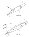
- Fig. 1A is a perspective view of a self-contained subdermal cryogenic remodeling probe and system, according to an embodiment of the invention.
- Fig. 1B is a partially transparent perspective view of the self-contained probe of Fig. 1A , showing internal components of the cryogenic remodeling system and schematically illustrating replacement treatment needles for use with the disposable probe.
- Fig. 2 schematically illustrates components that may be included in the treatment system.
- Fig. 3 is a schematic cross-sectional view of an embodiment of a distal portion of the probe and system of Fig. 1B , showing a replaceable needle and an pressure relief valve with a limited exhaust volume.
- Fig. 3A illustrates an exemplary fused silica cooling fluid supply tube for use in the replaceable needle of Fig. 3 .
- Fig. 4 is a more detailed view of a replaceable needle assembly for use in the system of Figs 1A and 1B .
- Figs. 5A-5C illustrate an exemplary supply valve for use in the probe and system of Figs. 1A and 1B .
- Figs. 6-8 illustrate skin-engaging surfaces that selectably limit an effective insertable length of the needle, that apply pain-dulling pressure, and that apply inflammation-inhibiting cooling to the skin before and/or during treatment of the target tissue, respectively.
- Figs. 9, 9A, and 9B schematically illustrate a needle having an elongate cross-section to enhance the volume of treated tissue.
- Fig. 10 schematically illustrates a thermal model of a cryogenic microprobe needle.
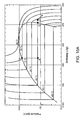
- Figs. 10A-10C graphically illustrate aspects of cryogenic cooling using nitrous oxide in the microprobe needles described herein.
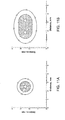
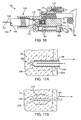
- Figs. 11A and 11B schematically illustrate cross-sectional views cooling with a one needle system and a multiple needle system.
- Fig. 12 graphically illustrates non-uniform cooling that can result from inadequate evaporation space within a small cryogenic needle probe.
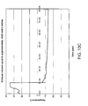
- Figs. 13A-13D graphically illustrate effects of changes in exhaust volume on the cooling response by a small cryogenic needle probe.
- Fig. 14 schematically illustrates a cryogenic microprobe needle system being used for a dermatological treatment.
- Fig. 15 is a flow chart schematically illustrating a method for treatment using the disposable cryogenic probe and system of Fig. 1B .
- Fig. 16 is a schematic cross-sectional view showing an alternative exemplary needle interface, along with the adjacent structures of the needle assembly and probe body.
- Figs. 17A and 17B are partial cross-sectional views schematically illustrating removal of a cryogenic cooling probe needle while at least a portion of the tissue remains frozen.
- Figs. 18A and 18B are partial cross-sectional views schematically illustrating how a depletion of liquid from a vaporizing cryogenic cooling fluid can be used to limit an effective treatment length on a portion of a cryogenic probe.
- Embodiments of the invention will facilitate remodeling of tissues disposed at and below the skin, optionally to treat a cosmetic defect, a lesion, a disease state, and/or so as to alter a shape of the overlying skin surface.
- the present invention may be the amelioration of lines and wrinkles, particularly by inhibiting muscular contractions which are associated with these cosmetic defects so as so improve an appearance of the patient.
- many embodiments of the invention will at least in part employ cold to immobilize muscles.
- nerves, muscles, and associated tissues may be temporarily immobilized using moderately cold temperatures of 10°C to -5°C without permanently disabling the tissue structures.
- a needle probe or other treatment device can be used to identify a target tissue structure in a diagnostic mode with these moderate temperatures, and the same probe (or a different probe) can also be used to provide a longer term or permanent treatment, optionally by ablating the target tissue zone and/or inducing apoptosis at temperatures from about -5°C to about -50°C.
- apoptosis may be induced using treatment temperatures from about -1°C to about -15°C, or from about -1°C to about - 19°C, optionally so as to provide a permanent treatment that limits or avoids inflammation and mobilization of skeletal muscle satellite repair cells.
- the duration of the treatment efficacy of such subdermal cryogenic treatments may be selected and controlled, with colder temperatures, longer treatment times, and/or larger volumes or selected patterns of target tissue determining the longevity of the treatment. Additional description of cryogenic cooling for treatment of cosmetic and other defects may be found in co-pending US Patent Application No. 11/295,204, filed on December 5, 2005 and entitled "Subdermal Cryogenic Remodeling of Muscle, Nerves, Connective Tissue, and/or Adipose Tissue (Fat)," the full disclosure of which is incorporated herein by reference.
- embodiments of the invention may also find applications for treatments of subdermal adipose tissues, benign, premalignant lesions, malignant lesions, acne and a wide range of other dermatological conditions (including dermatological conditions for which cryogenic treatments have been proposed and additional dermatological conditions), and the like.
- Embodiments of the invention may also find applications for alleviation of pain, including those associated with muscle spasms. Hence, a variety of embodiments may be provided.
- a system for cryogenic remodeling here comprises a self-contained probe handpiece generally having a proximal end 12 and a distal end 14.
- a handpiece body or housing 16 has a size and shape suitable for supporting in a hand of a surgeon or other system operator.
- a cryogenic cooling fluid supply 18 and electrical power source 20 are found within housing 16, along with a circuit 22 having a processor for controlling cooling applied by self-contained system 10 in response to actuation of an input 24.
- Some embodiments may, at least in part, be manually activated, such as through the use of a manual supply valve and/or the like, so that processors, electrical power supplies, and the like may be absent.
- Probe 26 Extending distally from distal end 14 of housing 16 is a tissue-penetrating cryogenic cooling probe 26.
- Probe 26 is thermally coupled to a cooling fluid path extending from cooling fluid source 18, with the exemplary probe comprising a tubular body receiving at least a portion of the cooling fluid from the cooling fluid source therein.
- the exemplary probe 26 comprises a 30 g needle having a sharpened distal end that is axially sealed.
- Probe 26 may have an axial length between distal end 14 of housing 16 and the distal end of the needle of between about 1/2 mm and 5 cm, preferably having a length from about 1 cm to about 3 cm.
- needles may comprise a stainless steel tube with an inner diameter of about .006 inches and an outer diameter of about .012 inches, while alternative probes may comprise structures having outer diameters (or other lateral cross-sectional dimensions) from about .006 inches to about .100 inches.
- needle probe 26 will comprise a 16 g or smaller size needle, often comprising a 20 g needle or smaller, typically comprising a 25 g or smaller needle.
- the exemplary cooling fluid supply 18 comprises a cartridge containing a liquid under pressure, with the liquid preferably having a boiling temperature of the less than 37°C.
- the fluid is thermally coupled to the tissue-penetrating probe 26, and the probe is positioned within the patient so that an outer surface of the probe is adjacent to a target tissue, the heat from the target tissue evaporates at least a portion of the liquid and the enthalpy of vaporization cools the target tissue.
- a valve (not shown) may be disposed along the cooling fluid flow path between cartridge 18 and probe 26, or along the cooling fluid path after the probe so as to limit the temperature, time, rate of temperature change, or other cooling characteristics.
- the valve will often be powered electrically via power source 20, per the direction of processor 22, but may at least in part be manually powered.
- the exemplary power source 20 comprises a rechargeable or single-use battery.
- the exemplary cooling fluid supply 18 comprises a single-use cartridge.
- the cartridge and cooling fluid therein may be stored and/or used at (or even above) room temperature.
- the cartridges may have a frangible seal or may be refillable, with the exemplary cartridge containing liquid N 2 O.
- a variety of alternative cooling fluids might also be used, with exemplary cooling fluids including fluorocarbon refrigerants and/or carbon dioxide.
- the quantity of cooling fluid contained by cartridge 18 will typically be sufficient to treat at least a significant region of a patient, but will often be less than sufficient to treat two or more patients.
- An exemplary liquid N 2 O cartridge might contain, for example, a quantity in a range from about 7 g to about 30 g of liquid.
- Processor 22 will typically comprise a programmable electronic microprocessor embodying machine readable computer code or programming instructions for implementing one or more of the treatment methods described herein.
- the microprocessor will typically include or be coupled to a memory (such as a non-volatile memory, a flash memory, a read-only memory (“ROM”), a random access memory (“RAM”), or the like) storing the computer code and data to be used thereby, and/or a recording media (including a magnetic recording media such as a hard disk, a floppy disk, or the like; or an optical recording media such as a CD or DVD) may be provided.
- a memory such as a non-volatile memory, a flash memory, a read-only memory (“ROM”), a random access memory (“RAM”), or the like
- a recording media including a magnetic recording media such as a hard disk, a floppy disk, or the like; or an optical recording media such as a CD or DVD
- Suitable interface devices such as digital-to-analog or analog-to-digital converters, or the like
- input/output devices such as USB or serial I/O ports, wireless communication cards, graphical display cards, and the like
- processor 22 may be integrated on a single processor board and may run a single program or may make use of a plurality of boards running a number of different program modules in a wide variety of alternative distributed data processing or code architectures.
- Supply valve may comprise an electrically actuated solenoid valve or the like operating in response to control signals from controller 22, and/or may comprise a manual valve.
- Exemplary supply valves may comprise structures suitable for on/off valve operation, and may provide venting of the cooling fluid path downstream of the valve when cooling flow is halted so as to limit residual cryogenic fluid vaporization and cooling. More complex flow modulating valve structures might also be used in other embodiments.
- the cooling fluid from valve 32 flows through a lumen 34 of a cooling fluid supply tube 36.
- Supply tube 36 is, at least in part, disposed within a lumen 38 of needle 26, with the supply tube extending distally from a proximal end 40 of the needle toward a distal end 42.
- the exemplary supply tube 36 comprises a fused silica tubular structure 36a having a polymer coating 36b (see Fig. 3A ) and extends in cantilever into the needle lumen 38.
- Supply tube 36 may have an inner lumen with an effective inner diameter 36c of less than about 200 ⁇ m, the inner diameter often being less than about 100 ⁇ m, and typically being less than about 40 ⁇ m.
- Exemplary embodiments of supply tube 36 have inner lumens of between about 15 and 50 ⁇ m, such as about 30 ⁇ m.
- An outer diameter or size 36d of supply tube 36 will typically be less than about 1000 ⁇ m, often being less than about 800 ⁇ m, with exemplary embodiments being between about 60 and 150 ⁇ m, such as about 90 ⁇ m or 105 ⁇ m.
- the tolerance of the inner lumen diameter of supply tubing 36 will preferably be relatively tight, typically being about +/-10 ⁇ m or tighter, often being +/- 5 ⁇ m or tighter, and ideally being +/- 3 ⁇ m or tighter, as the small diameter supply tube may provide the majority of (or even substantially all of)the metering of the cooling fluid flow into needle 26.
- supply tubes 36 having outer jackets of polyimide (or other suitable polymer materials) may bend within the surrounding needle lumen 38, the supply tube should have sufficient strength to avoid collapsing or excessive blow back during injection of cooling fluid into the needle.
- Polyimide coatings may also provide durability during assembly and use, and the fused silica/polymer structures can handle pressures of up to 100 kpsi.
- the relatively thin tubing wall and small outer size of the preferred supply tubes allows adequate space for vaporization of the nitrous oxide or other cooling fluid within the annular space between the supply tube 36 and surrounding needle lumen 38. Inadequate space for vaporization might otherwise cause a buildup of liquid in that annular space and inconsistent temperatures, as illustrated in Fig. 12 .
- Exemplary structures for use as supply tube 36 may include the flexible fused silica capillary tubing sold commercially by Polymicro Technologies, LLC of Phoenix, Arizona under model names TSP, TSG, and TSU, optionally including model numbers TSP 020090, TSP040105, and/or others.
- the cooling fluid injected into lumen 38 of needle 26 will typically comprises liquid, though some gas may also be injected. At least some of the liquid vaporizes within needle 26, and the enthalpy of vaporization cools the tissue engaged by the needle. Controlling a pressure of the gas/liquid mixture within needle 26 substantially controls the temperature within lumen 38, and hence the treatment temperature range of the tissue.
- a relatively simple mechanical pressure relief valve 46 may be used to control the pressure within the lumen of the needle, with the exemplary valve comprising a valve body 48 (here in the form of a ball bearing) urged against a valve seat 50 by a biasing spring 52.
- a large volume along the cooling fluid pathway between the exit from the supply tube and exit from the pressure relief valve 46 may cause excessive transients.
- a large volume in this area may result in initial temperatures that are significantly colder than a target and/or steady state temperature, as can be seen in Fig. 13D .
- This can be problematic, particularly when (for example) the target temperature is only slightly warmer than an undesirable effect inducing temperature, such as when remodeling through apoptosis or the like while seeking to inhibit necrosis.
- the pressure relief valve 46 may be integrated into a housing 54 supporting needle 26, with the valve spring 52 being located outside the valve seat (and hence the pressure-control exit from pressure relief valve 46).
- pressure relief valve 46 is also located adjacent the interface between the needle assembly and probe handpiece housing 54.
- a detent 56 may be engaged by a spring supported catch to hold the needle assembly releasably in position, and the components of the needle assembly 26A (such as a brass or other metallic housing, a polyimide tubing 58, needle 26, and the like) may be affixed together using adhesive.
- the needle assembly and handpiece housing may have corresponding threads for mounting and replacement of the needle assembly.
- O-rings 60 can seal the cooling fluid pathway.
- Figs. 13A-13C present additional details on the effects of exhaust volume on cooling transients.
- a graph of temperature over time is shown for the outside temperature of an in vivo 30g cooling needle with a target temperature of about -12°C.
- the devices were constructed with different exhaust volumes, with the volume being greater than about 0.009 in 3 in the embodiment of Fig. 13A .
- the embodiment of Figs. 13B and 13C had exhaust volumes of about 0.009 in 3 and about .0025 in 3 , respectively.
- the data collection rate was about 0.7 sec for the embodiment of Fig. 13A , while the embodiments of Figs. 13B and 13C both had data collection rates of about 0.1 sec, so that the actual nadir for the embodiment of Fig. 13A may have actually been significantly lower than that shown.
- the exhaust volume is preferably less than about 0.05 in 3 ., typically being less than 0.01 in 3 and/or 0.009 in 3 , and ideally being less than 0.005 in 3 .
- the supply valve might be cycled on and off, typically by controller 22, with a timing sequence that would limit the cooling fluid flowing so that only vaporized gas reached the needle lumen (or a sufficiently limited amount of liquid to avoid excessive dropping of the needle lumen temperature). This cycling might be ended once the exhaust volume pressure was sufficient so that the refrigeration temperature would be within desired limits during steady state flow.
- FIG. 3 the valve is shown in the "on" configuration, with O-rings 60 sealing either side of the cooling fluid flow path and the cooling fluid flowing around the movable valve member.
- Figs. 5A-5C the cooling fluid flows through a passage 64 that extends axially along an alternative valve body of valve body 32' when the valve is in the on configuration (seen in Fig. 5B ), with the O-rings being disposed between recesses in the movable valve body so as to allow the valve to operate when the valve body is in any rotational orientation about its axis.
- the cooling fluid flow path downstream of the valve is vented when the valve is in the "off" configuration (in the embodiment of Fig. 3 , by channel 66, and in the embodiment of Figs. 5A-5C by the vaporizing cooling fluid flowing through the annular space between the valve body and the adjacent housing 54 so as to preserve the cooling fluid within the movable valve body).
- Venting of the cooling fluid from the cooling fluid supply tube 36 when the cooling fluid flow is halted by supply valve 32, 32' is advantageous to provide a rapid halt to the cooling of needle 26.
- a 2.5 cm long 30 g needle cooled to an outside temperature of -15°C might use only about 0.003 g/sec of nitrous oxide after the system approaches or reaches steady state (for example, 10 seconds after initiation of cooling).
- Fig. 10 Analytical models that may be used to derive these cooling flows include that illustrated in Fig. 10 , which may be combined with the properties of the cooling fluid (such as the pressure/enthalpy diagram of nitrous oxide seen in Fig. 10A ) and the thermal properties of tissue shown in Table I to determine theoretical minimum cooling fluid flow rates (see Fig. 10B ), theoretical minimum cooling fluid quantities (see Fig. 10C ), and the like.
- Fluid supply 18 may be initially opened for use by penetrating a frangible seal of the cartridge with a pierce point 70 (such as by tightening a threaded cartridge support coupled to housing 54), with the nitrous being filtered by a filter 72 before being transmitted further along the cooling fluid path.
- Suitable filters may have pore sizes of from about 6 to about 25 ⁇ m, and may be available commercially from Porex of Georgia (or a variety of alternative suppliers), or may comprise a fine stainless steel screen (such as those having a mesh size of 635 5 with 0.0009" wire and spacing between the wire edges of approximately 0.0006"), or the like.
- a wide variety of epoxy or other adhesives 74 may be used, and the replaceable needle housing 24A and other structural components may comprise a wide variety of metals or polymers, including brass or the like. Fins 76 may be included to help vaporize excess cooling liquid traveling proximally of the insertable length of needle 26.
- Very fine needles will typically be used to deliver to cooling at and/or below the surface of the skin. These needles can be damaged relatively easily if they strike a bone, or may otherwise be damaged or deformed before or during use. Fine needles well help inhibit damage to the skin during insertion, but may not be suitable for repeated insertion for treatment of numerous treatment sites or lesions of a particular patient, or for sequential treatment of a large area of the patient. Hence, the structures shown in Figs. 1B , 3 , and 4 allow the use probe bodies 16, 54 with a plurality of sequentially replaceable needles.
- O-rings 60 help to isolate the cooling fluid supply flow (which may be at pressures of up to about 900 psi) from the exhaust gas (which may be at a controlled pressure in a range between about 50 and 400 psi, depending on the desired temperature).
- Exemplary O-rings may comprise hydrogenated Buna-N O-rings, or the like.
- needle assemblies having differing numbers of needles in a needle array may also be selected and mounted to the probe body.
- Other embodiments may employ a single needle array fixedly mounted to the probe body, or a plurality of replaceable needle assemblies which all include the same number of needles.
- cooling fluid flow to a plurality of needles may be provided, for example, by inserting and bonding a plurality of fused silica supply tubes into a 0.010 polyimide tubing 58 or header within the needle assembly, and by advancing the distal end of each supply tube into a lumen of an associated needle 26.
- the needles might vent into a common exhaust space coaxially around polyimide tubing 58 in a manner similar to the single needle design shown. This can increase the quantity of tissue treated adjacent and/or between needles, as can be seen by comparing the theoretical 15 second exposures to one and two needles having a -15°C probe surface, as shown in Figs. 11A and 11B , respectively.
- a distally oriented surface 82 supported by probe body 54 adjacent and/or around the proximal end of the needles may be configured to limit heat transfer to or from the skin when the needle 26 is inserted so that surface 82 engages the skin and cooling fluid flows into the needle.
- Exemplary heat transfer limiting surfaces may be formed, for example, from a small rigid foam pad or body 84. Closed cell polyethylene foam or StyrofoamTM foam bodies may be used. As seen in Fig.
- an alternatively selectable set of bodies may also have differing thicknesses between the skin engaging-surface 82 and a surface 86 that engages the distal portion of the probe body.
- a user can then select an insertable length of the needle by selecting an appropriate probe body 84, 84a, 84b and mounting the selected probe body onto the needles.
- Skin engaging surface 82 of bodies 84, 84a, and 84b (or some other skin engaging surface adjacent the distal end of the needle) may be used to apply pressure to the skin, lesion, and/or target tissue during treatment.
- Alternative insertable length varying arrangements may also be provided, including those having threaded or other articulatable structures supporting the skin engaging surface 82 relative to the adjacent probe body 54 and the like.
- the application of pressure before, during, and/or after cooling may help dull or otherwise inhibit sharp pain. Such pain may otherwise result from the skin penetration, cooling, or thawing of the target and/or collateral tissues. It may also be beneficial to obscure the patient's view of the cooling needles, and/or to cover the needles when not in use so as to inhibit needle-stick injuries and potential disease transmission.
- skin-engaging surface 82 may be supported by an articulatable support structure having a first configuration (shown in solid in Fig. 7 ) and a second configuration (shown dashed in Fig. 7 ).
- a simple spring mechanism may be used to apply a desired contact force between the skin-engaging surface 82 and the patient before insertion and during cooling. More sophisticated arrangements can also be employed in which the needle is driven distally and then proximally relative to the skin engaging surface appropriate times after sufficient pressure is applied to the patient, and the like.
- FIG. 8 still further alternative embodiments may be provided, in this case to apply different cooling temperatures to the patient, and/or to apply cooling to the skin surface and to a target tissue adjacent needle 26.
- different cooling temperatures such as to about -10°C
- a target tissue TT cylinder around needle 26 sufficient to kill bacteria in the sebaceous gland and enlarged follicle opening (such as to about -20°C).
- This dual temperature treatment may be particularly beneficial for severe forms of acne involving cysts or nodules.
- tissue engaging surface 82 that surface may be thermally coupled to a chamber 88.
- Cooling fluid may be transmitted into chamber 88 by a port of a cooling fluid supply tube 36, and the pressure of chamber 88 (and hence the temperature within the chamber) can optionally be controlled by a dedicated additional pressure relief valve 46a. As the pressure within chamber 88 may differ from that within the needle, different treatment temperatures may be provided.
- the structures described herein can also be combined, for example, with the dual skin surface/needle temperature treatment structure of Fig. 8 being compatible with the replaceable needle systems of Figs. 1B , 3 , and/or 4.
- the dual skin surface/needle treatment systems and methods may also be compatible, for example, with the articulatable skin surface supports of Fig. 7 so as to apply cooled pressure to the skin prior to and/or during needle insertion using a flexible fluid supply tube or the like.
- Still further alternatives may also be provided, including systems that generate a high rate of cooling to promote necrosis of malignant lesions or the like.
- High cooling rates limit osmotic effects in the target tissue.
- Slow cooling may tend to promote ice formation between cells rather than within cells due to the osmotic effect.
- the needle probes described herein will often be well suited to induce rapid cooling rates of the target tissue by vaporizing the cooling fluid in close thermal and spatial proximity to that target tissue.
- cooling rates of about 25°C/sec or more, or even about 50°C/sec or more can be provided.
- needles having circular cross-sectional shapes can often be used, but may not always provide the desired surface area for the cross-sectional area of the needle. Increased surface area may decrease the amount of time the needle is inserted to cool a volume of tissue to a temperature in a target range. Hence, a needle with an elongate outer cross-section such as elliptical needle 90 may be desirable.
- a distal cutting edge 92 at the distal tip may facilitate insertion and a circular cross-section 94 near the proximal end may limit cooling adjacent the skin, while cooling of the target tissue therebetween is enhanced by elliptical cross-section 96.
- Method 100 facilitates treating a patient using a cryogenic cooling system having a self-contained disposable handpiece and replaceable needles such as those of Fig. 1B .
- Method 100 generally begins with a determination 110 of the desired tissue remodeling and results, such as the alleviation of specific cosmetic wrinkles of the face, the inhibition of pain from a particular site, the alleviation of unsightly skin lesions or cosmetic defects from a region of the face, or the like.
- Appropriate target tissues for treatment are identified 112 (such as the subdermal muscles that induce the wrinkles, a tissue that transmits the pain signal, or the lesion-inducing infected tissues), allowing a target treatment depth, target treatment temperature profile, or the like to be determined 114.
- An appropriate needle assembly can then be mounted 116 to the handpiece, with the needle assembly optionally having a needle length, skin surface cooling chamber, needle array, and/or other components suitable for treatment of the target tissues.
- Simpler systems may include only a single needle type, and/or a first needle assembly mounted to the handpiece.
- pressure, cooling, or both may be applied 118 to the skin surface adjacent the needle insertion site before, during, and/or after insertion 120 and cryogenic cooling 122 of the needle and associated target tissue.
- the needle can then be retracted 124 from the target tissue. If the treatment is not complete 126 and the needle is not yet dull 128, pressure and/or cooling can be applied to the next needle insertion location site 118, and the additional target tissue treated.
- any needles that are dulled (or otherwise determined to be sufficiently used to warrant replacement, regardless of whether it is after a single insertion, 5 insertions, or the like) during the treatment may be replaced with a new needle 116 before the next application of pressure/cooling 118, needle insertion 120, and/or the like.
- the used handpiece and needles can be disposed of 130.
- target treatment temperatures, times, and cycles may be applied to differing target tissues to as to achieve the desired remodeling.
- desired temperature ranges to temporarily and/or permanently disable muscle, as well as protect the skin and surrounding tissues may be indicated by Table II as follows: Table II Temperature Skin Muscle/Fat 37°C baseline baseline 25°C cold sensation 18°C reflex vasodilation of deep blood vessels 15°C cold pain sensation 12°C reduction of spasticity 10°C very cold sensation reduction of chronic oedema Hunting response 5°C pain sensation 0°C freezing point -1°C Phase transition begins minimal apoptosis -2°C -3°C Peak phase transition moderate apoptosis -5°C tissue damage -8°C Completion of phase transition -10°C considerable apoptosis -15°C extensive apoptosis mild-moderate necrosis -19°C adoptosis in some skeletal muscle tissues -40°
- tissue treatment temperatures may be employed per Table III as follows: Table III Cooled Temperature Range Time Effectiveness Purpose ⁇ 0°C Treatment lasts only while the needle is inserted into the target tissue. Can be used to identify target tissues. From 0°C to -5°C Often lasts days or weeks, and target tissue can repair itself. Embodiments may last hours or days. Temporary treatment. Can be used to evaluate effectiveness of remodeling treatment on skin surface shape or the like. From -5°C to -15°C Often lasts months to years; and may be permanent. Limited muscle repair. Embodiments may last weeks to months. Long term, potentially permanent cosmetic benefits.
- Embodiments may provide permanent treatment.
- Apoptosis may exhibit a non-inflammatory cell death. Without inflammation, normal muscular healing processes may be inhibited. Following many muscular injuries (including many injuries involving necrosis), skeletal muscle satellite cells may be mobilized by inflammation. Without inflammation, such mobilization may be limited or avoided. Apoptotic cell death may reduce muscle mass and/or may interrupt the collagen and elastin connective chain.
- Temperature ranges that generate a mixture of these apoptosis and necrosis may also provide long-lasting or permanent benefits.
- a permanent effect may be advantageous.
- both apoptosis and necrosis may produce long-term or even permanent results in adipose tissues, since fat cells regenerate differently than muscle cells.
- FIG. 16 an exemplary interface 160 between a cryogenic cooling needle probe 162 and the associated probe body structure 164 are illustrated, along with adjacent portions of the needle, valve, probe body, and the like.
- Needle probe 162 is included in a needle assembly having a needle hub 166 with a lumen containing a polyimide tube 168 around a fused silica cooling fluid supply tube with its polyimide jacket 170.
- O-rings 172 seal in exhaust gas path 174 and inlet cooling fluid path 176, with the inlet path having a vent 178 to minimize run-on cooling when the cooling fluid supply is shut off by a valve 180, as generally described above.
- the valve is here actuated by a motor 182, while the exhaust gas pressure is controlled using a biasing spring and ball valve 184 as described above.
- a hollow set screw 186 can be used to assemble and/or adjust the pressure relief valve, and a thermistor 188 can be used to sense cooling gas flow.
- cryogenic cooling probes 196, 198 are inserted into a target tissue TT and a flow of cryogenic cooling fluid is injected into the needle as generally described above.
- a region 200 of target tissue TT is cooled sufficiently to freeze and effect the desired remodeling of at least a portion of the target tissue.
- a lubricious coating 202 facilitates removal of the needle while at least a portion of the frozen target tissue remains frozen.
- the lubricious coating 202 may comprise a material having a thermal conductivity which is significantly less than that of the underlying probe structure 204.
- Coating 202 may have a thickness which is significantly less than that of the underlying probe structure 204, limiting the total insulation effect of the coating, and/or an interior temperature of probe 196 may be reduced so as to provide the desired overall cooling treatment. While it may be counterintuitive to cool the target tissue through a thermally insulating lubricious coating, the ability to more rapidly remove probe 196 from the patient can significantly increase the speed with which procedures may be performed, particularly when a large number of insertion/cooling/removal cycles are involved, and/or when the thaw time is at least half as long as (often being as long as or longer than) the active cooling time.
- a small surface 206 of probe 196 may be free of lubricious coating 202.
- the underlying probe structure 204 comprises an electrical conductor such as stainless steel or some alternative metal
- the uncovered surface portion 206 maybe used as an electrode for neurostimulation during positioning of probe 196 or the like.
- microneedle probe 198 has a cross-sectional size of a 20-gauge needle or less, preferably comprising a 25-gauge needle or smaller, and ideally comprising a 30-gauge needle.
- These small diameter microneedle probes have little thermal mass and can be warmed relatively quickly by conduction from adjacent tissues and/or by any warm fluids flowing therein. As a result, while a major portion 208 of the target tissue remains frozen a layer 210 disposed between the still-frozen region and probe 198 may facilitate safe removal of the probe from the patient.
- Thawed layer 210 may comprise thawed target tissue, thawed extracellular fluids, or the like. Small needles also have small probe/tissue interface surface areas which may limit the total stiction between the probe and frozen tissue. Regardless of any particular mechanism of action, the use of small diameter cryogenic microneedles may allow safe removal of the probe from a treated tissue in a time which is significantly less than that associated with complete thaw of the iceball that has been formed. Exemplary embodiments using a lubricious coating and/or small diameter probe may allow the probe to be removed within about 10 seconds of the cooling, optionally allowing safe removal within about 5 seconds of cooling or even within about 3 seconds of cooling.
- a cryogenic cooling probe 220, 222 can be used to control the length of the probe that applies a therapeutic cooling.
- Probes 220, 222 are replaceably supported by a probe body 224 via a needle receptacle or interface, as generally described above.
- Each probe includes a lumen 226 with a cooling fluid supply tube 228 extending to a distal port 230.
- the supply tube can be used to meter cooling fluid.
- cooling of the target tissue TT along a distal portion 232 of probe 228 is cooled by evaporation of the liquid included in the cryogenic cooling fluid.
- cooling of a collateral tissue CT proximal of the target tissue TT may be limited by controlling the amount of cooling fluid flow so that the vaporizing liquid is depleted by the time the flow reaches a proximal portion 234 of the probe.
- a greater length of probe 222 is cooled by providing a relatively larger quantity of cooling fluid (and liquid) flowing from the supply tube 238 into lumen 226 via port 230, so that liquid remains present for vaporization throughout a longer distal portion 232 of the probe. Note that the difference in lengths of the cooled portion 232 may be provided despite making use of an outer probe structure that is similar in cross section and/or overall length.
- proximal portion 234 of probes 220, 222 may be cooled somewhat (via conduction from the distal portion 232 of the probe, from the passage of gas vaporized from the gas of the cooling fluid, or the like), a temperature of collateral tissue CT may remain above the remodeling treatment temperature of a treatment zone 238 within the target tissue. Hence, the collateral tissue may avoid injury despite the absence of any additional insulation on the proximal portion of the probe. This also facilitates the use of differing treatment zones 238 at different locations for a particular patient through the selection of needle assemblies having appropriate cooling fluid supply paths with the desired differing cooling fluid flow characteristics.
- one or more temperature feedback loops may be used to control the treatments, with the tissue temperature optionally being taken using a temperature sensing needle having a temperature sensor disposed adjacent an outer cooled skin engaging surface of the needle.
- the scope of the present invention is limited solely by the independent claims.
Abstract

Description
- NOT APPLICABLE
- NOT APPLICABLE
- NOT APPLICABLE
- The present invention is generally directed to medical devices, systems, and methods, particularly for cooling-induced remodeling of tissues. Embodiments of the invention include devices, systems, and methods for applying cryogenic cooling to dermatological tissues so as to selectively remodel one or more target tissues along and/or below an exposed surface of the skin. Embodiments may be employed for a variety of cosmetic conditions, optionally by inhibiting undesirable and/or unsightly effects on the skin (such as lines, wrinkles, or cellulite dimples) or on other surrounding tissue. Other embodiments may find use for a wide range of medical indications. The remodeling of the target tissue may achieve a desired change in its behavior or composition.
- The desire to reshape various features of the human body to either correct a deformity or merely to enhance one's appearance is common. This is evidenced by the growing volume of cosmetic surgery procedures that are performed annually.
- Many procedures are intended to change the surface appearance of the skin by reducing lines and wrinkles. Some of these procedures involve injecting fillers or stimulating collagen production. More recently, pharmacologically based therapies for wrinkle alleviation and other cosmetic applications have gained in popularity.
- Botulinum toxin type A (BOTOX®) is an example of a pharmacologically based therapy used for cosmetic applications. It is typically injected into the facial muscles to block muscle contraction, resulting in temporary enervation or paralysis of the muscle. Once the muscle is disabled, the movement contributing to the formation of the undesirable wrinkle is temporarily eliminated. Another example of pharmaceutical cosmetic treatment is mesotherapy, where a cocktail of homeopathic medication, vitamins, and/or drugs approved for other indications is injected into the skin to deliver healing or corrective treatment to a specific area of the body. Various cocktails are intended to effect body sculpting and cellulite reduction by dissolving adipose tissue, or skin resurfacing via collagen enhancement. Development of non-pharmacologically based cosmetic treatments also continues. For example, endermology is a mechanical based therapy that utilizes vacuum suction to stretch or loosen fibrous connective tissues which are implicated in the dimpled appearance of cellulite.
- While BOTOX® and/or mesotherapies may temporarily reduce lines and wrinkles, reduce fat, or provide other cosmetic benefits they are not without their drawbacks, particularly the dangers associated with injection of a known toxic substance into a patient, the potential dangers of injecting unknown and/or untested cocktails, and the like. Additionally, while the effects of endermology are not known to be potentially dangerous, they are brief and only mildly effective.
- In light of the above, it would be desirable to provide improved medical devices, systems, and methods, particularly for treatment of wrinkles, fat, cellulite, and other cosmetic defects. It would be particularly desirable if these new techniques provided an alternative visual appearance improvement mechanism which could replace and/or compliment known bioactive and other cosmetic therapies, ideally allowing patients to decrease or eliminate the injection of toxins and harmful cocktails while providing similar or improved cosmetic results. It would also be desirable if such techniques were performed percutaneously using only local or no anesthetic with minimal or no cutting of the skin, no need for suturing or other closure methods, no extensive bandaging, and limited or no bruising or other factors contributing to extended recovery or patient "down time". It would further be desirable to provide new devices, systems, and methods for treatment of other cosmetic and/or dermatological conditions (and potentially other target tissues), particularly where the treatments may be provided with greater accuracy and control, less collateral tissue injury and/or pain, and greater ease of use.
- The present invention generally provides improved medical devices, systems, and methods. Embodiments may be particularly well suited for the treatment of dermatological and/or cosmetic defects, and alternative embodiments may be configured for treatment of a wide range of target tissues. Some embodiments of the present invention apply cooling with at least one small, tissue-penetrating probe, the probe often comprising a needle having a size suitable for inserting through an exposed surface of the skin of a patient without leaving a visible scar. The cooling may remodel one or more target tissue so as to effect a desired change in a composition of the target tissue and/or a change in its behavior. Unlike the large format cryogenic cooling systems of the past, small cryogenic cooling needle probes may dull or be damaged by insertion. Exemplary embodiments make use of replaceable needle probes supported by a probe body handle, with small needle probes often being replaced during treatment of a single patient. Careful control over the cryogenic cooling fluid introduced into a needle probe can allow the length of the active cooling to be controlled through depletion of evaporating cryogenic cooling liquid. Hence, even needles having similar external structures may provide differing lengths of effective remodeling along the needle axis. Surprisingly, small cryogenic cooling needles and/or other cryogenic cooling probes having a lubricious coating will allow safe removal of the probe from the treatment region while at a least a portion of the tissue remains frozen, significantly decreasing the overall time for a procedure involving many insertion/freeze/removal cycles.
- In a first aspect, the invention provides a method for treating tissue of a patient. The method comprises inserting a first needle through a first insertion point and into a first target region of the tissue by manipulating handle. The handle supports the first needle via a needle interface. The first target region is cooled with the first needle and the first needle is removed from the patient. The first needle is replaced in the needle interface with a second needle. The second needle is inserted through the second insertion point and into a second target region of the tissue by manipulating the handle. The second target region is cooled with the second needle.
- The second needle may optionally have size and/or cooling characteristics which are similar to those of the first needle. Such needle replacement may be particularly useful when using small needles that can become dull after a limited number of insertions into the patient. In other embodiments, the second needle may have size and/or cooling characteristics that differ from those of the first needle, such as having a different length, needle gauge size or diameter, active cooling length, or the like. In some embodiments, the first needle may be included in a first needle assembly that has only a single needle, while the second needle is included in a needle assembly having a plurality of needles. The needles of the second needle assembly may be simultaneously inserted into the target tissue, with the needles often being substantially parallel. A cooling fluid supply tube (and its associated lumen) may extend from a common cooling fluid supply of the needle interface, and cooling fluid vaporization lumens of each needle may flow to a common pressure-regulated exhaust path, also often via the needle interface. In many embodiments, cooling with the plurality of needles of the second needle assembly may be performed so that the cooled tissues are remodeled throughout a contiguous treatment zone. In other embodiments, the needle spacing and the like may result in a plurality of discrete remodeled zones.
- Typically, the first and second needles will each have a sharpened distal tip and a 20-gauge needle size or less. The needles may be disposed of after use to avoid inserting a dull needle into the patient, with the needles optionally being inserted a single time, or alternatively being inserted a plurality of times (often less than ten times, and in many cases, less than five times) through the patient's skin. The handle of the system may be included in a probe body, and a fluid supply cartridge and battery may be supported and/or housed by the probe body. The probe body may be disposed of so that one or all of these components are used to treat only a single patient. Such a structure also helps avoid any requirement for a tether, power port, flexible supply line, or the like, which might otherwise inhibit manipulation and use of the handheld probe. Cooling will often be terminated by closing a cooling fluid shutoff valve disposed along a cooling fluid supply path between a cooling fluid source and the lumen. As cooling may be performed by evaporating liquid cooling fluid within a lumen of the needle, a volume of the supply path between the valve and the lumen will preferably be quite low (typically being less than .05 cubic inches, optionally being less than .005 cubic inches) so as to allow more accurate control of the treatment time. The supply path between the valve and the needle lumen is preferably vented when the valve is closed so as to avoid continuing cooling by any residual cryogenic liquid within that volume.
- In another aspect, the invention provides a method for treating a target tissue of a patient. The method comprises inserting a cooling probe distally through a collateral tissue and into the target tissue. The cooling probe has a lumen with a distal portion adjacent the target tissue and a proximal portion adjacent the collateral tissue. Cooling fluid is introduced into the distal portion of the lumen, and evaporation of liquid from the cooling fluid into gas occurs as the cooling fluid flows proximally within the distal portion of the lumen. This evaporation occurs so that the evaporation cools the target tissue sufficiently for the desired remodeling treatment. Additionally, the evaporation occurs so that the liquid is depleted from the cooling fluid sufficiently when the gas passes through the proximal portion of the lumen to inhibit cooling of the collateral tissue.
- The target tissue along the distal portion of the lumen can be cooled to a treatment temperature which is in a first temperature range. The collateral tissue along the proximal portion of the lumen will typically be cooled to a collateral tissue temperature in a second temperature range that is warmer than the first temperature range. Note that the differential in cooling effects between the distal and proximal lumen portions may occur despite the structure of the needle having a substantially uniform and/or consistent cross-section along the proximal and distal portions. Advantageously, a length of the distal, tissue remodeling portion may be selected from among a plurality of alternative lengths by selecting the probe for mounting to a probe body. Alternative probes may include differing cooling fluid supply paths so as to introduce differing cooling fluid supply flows with corresponding differing liquid depletion characteristics. More specifically, using otherwise similar probe structures having differing cooling fluid supply tubes with differing inner diameters and/or differing lengths may effectively vary the axial length of tissue that is remodeled, particularly where a significant portion of the metering of the cooling fluid flow is effected by the flow resistance of the cooling fluid supply lumen. Advantageously, the treatment temperatures along the distal portion may remain substantially uniform so long as there continues to be a sufficient mixture of cooling liquid and evaporated gas in the cooling fluid flow. As the cooling fluid liquid is depleted from that flow, temperatures of the flow may increase and/or the heat transfer from the surrounding probe structure (and tissue) may significantly decrease, with the change in cooling during a relatively short and predictable axial length of the probe.
- In another aspect, the invention provides a method for remodeling a target tissue of a patient. The method comprises inserting a cooling probe distally into the target tissue. The target tissue is cooled sufficiently to freeze a region of the target tissue. The cooling probe is removed from the target tissue while the region remains frozen.
- In many embodiments, the cooling probe may be removed less than 15 seconds after the termination of cooling, with the probe typically being removed less than 10 seconds after the cooling (or even less than 5 seconds after the cooling). Such counterintuitive removal of a cryogenic cooling probe from a still-frozen treatment region may be safely performed, for example, where the cooling is effected using a cooling probe having a cross-sectional size of a 20-gauge needle or less, the needle often being 25 gauge or less, and ideally being 30 gauge. A melted zone may be relatively quickly formed between such a probe and the surrounding frozen tissue to facilitate safe removal of the probe, despite the region remaining frozen. Hence, not all of the initially-frozen tissue may remain frozen during removal, although the majority of the tissue that has been frozen may remain frozen in many embodiments.
- Many embodiments of the present invention may facilitate removal of a cryogenic treatment probe from a still-frozen tissue region by cooling the target tissue through a lubricious coating of the probe. Although the lubricious coating will often have a thermal conductivity which is significantly lower than that of the underlying probe material (the probe material typically comprising stainless steel hypotube or the like for small needle probes), the total thermal transfer from the target tissue can be facilitated by using a lubricious coating having a thickness which is significantly less than that of the probe material. Additionally, the internal temperature of a cryogenic fluid vaporization chamber or lumen may be selected to generate the desired cooling characteristics despite the thermal insulation of the lubricious coating. Nonetheless, overall treatment times will be significantly shorter, particularly where a large number of insertion/cooling/removal cycles are employed, and/or where the total cooling time is relatively short compared to the time for a total thaw of the frozen tissue.
- In another aspect, the invention provides a system for treating tissue of a patient. The system comprises a first needle having a proximal end, a distal tissue-penetrating end, a lumen therebetween, and a cooling fluid supply lumen extending distally to a port within the needle lumen. The needle has a size of a 20-gauge needle or less. A second needle has a proximal end, a distal tissue-penetrating end and a lumen therebetween. A cooling fluid supply lumen extends distally to a port within the lumen of the second needle, the needle also having a size of a 20-gauge needle or less. A probe body has a handle supporting a cooling fluid source and a needle interface for sequentially receiving the first and second needles. Vaporization within the lumen of the received needle cools the tissue when the needle is inserted therein and cooling fluid is introduced from the cooling fluid supply through the port.
- In another aspect, the invention provides a system for treatment of the target tissue of a patient. The patient has a collateral tissue adjacent the target tissue, and the system comprises a probe having a proximal end and a distal end. The distal end is insertable through the collateral tissue and into the target tissue. The inserted probe has a lumen with a proximal portion adjacent the target tissue and a distal portion adjacent the collateral tissue when the distal end is inserted. A cooling fluid source is in fluid communication with the distal portion of the lumen. The source is configured so that, when cooling fluid flows from the source into (and proximally along) the lumen of the inserted probe, liquid of the cooling fluid evaporates into gas within the distal portion of the lumen such that the evaporation cools the target tissue sufficiently for the treatment. Additionally, the liquid is depleted sufficiently when the cooling fluid passes through the proximal portion of the lumen to inhibit cooling of the collateral tissue.
- In yet another aspect, the invention provides a system for remodeling a target tissue of the patient. The system comprises a cooling probe insertable distally into the target tissue. The cooling probe has a cooling surface for cooling the target tissue sufficiently to freeze a region of the target tissue. A lubricious coating is disposed over the cooling surface of the probe to facilitate removing the cooling probe from the target tissue while the region remains frozen.
- Exemplary lubricious and/or hydrophobic coatings include polymers, such as a PTFE Teflon™ polymers, a silicone, or the like. Typical thicknesses of the coating may be from about 0.00005 inches to about 0.001 inches, with an exemplary PTFE polymer coating having a thickness of about 0.0005 inches and exemplary silicone coatings being thinner. In some embodiments, a portion of the probe (such as a distal end or small region near the distal end) may be free of the coating so as to allow use of the coating-free region as an electrode or the like.
-
Fig. 1A is a perspective view of a self-contained subdermal cryogenic remodeling probe and system, according to an embodiment of the invention. -
Fig. 1B is a partially transparent perspective view of the self-contained probe ofFig. 1A , showing internal components of the cryogenic remodeling system and schematically illustrating replacement treatment needles for use with the disposable probe. -
Fig. 2 schematically illustrates components that may be included in the treatment system. -
Fig. 3 is a schematic cross-sectional view of an embodiment of a distal portion of the probe and system ofFig. 1B , showing a replaceable needle and an pressure relief valve with a limited exhaust volume. -
Fig. 3A illustrates an exemplary fused silica cooling fluid supply tube for use in the replaceable needle ofFig. 3 . -
Fig. 4 is a more detailed view of a replaceable needle assembly for use in the system ofFigs 1A and 1B . -
Figs. 5A-5C illustrate an exemplary supply valve for use in the probe and system ofFigs. 1A and 1B . -
Figs. 6-8 illustrate skin-engaging surfaces that selectably limit an effective insertable length of the needle, that apply pain-dulling pressure, and that apply inflammation-inhibiting cooling to the skin before and/or during treatment of the target tissue, respectively. -
Figs. 9, 9A, and 9B schematically illustrate a needle having an elongate cross-section to enhance the volume of treated tissue. -
Fig. 10 schematically illustrates a thermal model of a cryogenic microprobe needle. -
Figs. 10A-10C graphically illustrate aspects of cryogenic cooling using nitrous oxide in the microprobe needles described herein. -
Figs. 11A and 11B schematically illustrate cross-sectional views cooling with a one needle system and a multiple needle system. -
Fig. 12 graphically illustrates non-uniform cooling that can result from inadequate evaporation space within a small cryogenic needle probe. -
Figs. 13A-13D graphically illustrate effects of changes in exhaust volume on the cooling response by a small cryogenic needle probe. -
Fig. 14 schematically illustrates a cryogenic microprobe needle system being used for a dermatological treatment. -
Fig. 15 is a flow chart schematically illustrating a method for treatment using the disposable cryogenic probe and system ofFig. 1B . -
Fig. 16 is a schematic cross-sectional view showing an alternative exemplary needle interface, along with the adjacent structures of the needle assembly and probe body. -
Figs. 17A and 17B are partial cross-sectional views schematically illustrating removal of a cryogenic cooling probe needle while at least a portion of the tissue remains frozen. -
Figs. 18A and 18B are partial cross-sectional views schematically illustrating how a depletion of liquid from a vaporizing cryogenic cooling fluid can be used to limit an effective treatment length on a portion of a cryogenic probe. - The present invention provides improved medical devices, system, and methods. Embodiments of the invention will facilitate remodeling of tissues disposed at and below the skin, optionally to treat a cosmetic defect, a lesion, a disease state, and/or so as to alter a shape of the overlying skin surface.
- Among the most immediate applications of the present invention may be the amelioration of lines and wrinkles, particularly by inhibiting muscular contractions which are associated with these cosmetic defects so as so improve an appearance of the patient. Rather than relying entirely on a pharmacological toxin or the like to disable muscles so as to induce temporary paralysis, many embodiments of the invention will at least in part employ cold to immobilize muscles. Advantageously, nerves, muscles, and associated tissues may be temporarily immobilized using moderately cold temperatures of 10°C to -5°C without permanently disabling the tissue structures. Using an approach similar to that employed for identifying structures associated with atrial fibrillation, a needle probe or other treatment device can be used to identify a target tissue structure in a diagnostic mode with these moderate temperatures, and the same probe (or a different probe) can also be used to provide a longer term or permanent treatment, optionally by ablating the target tissue zone and/or inducing apoptosis at temperatures from about -5°C to about -50°C. In some embodiments, apoptosis may be induced using treatment temperatures from about -1°C to about -15°C, or from about -1°C to about - 19°C, optionally so as to provide a permanent treatment that limits or avoids inflammation and mobilization of skeletal muscle satellite repair cells. Hence, the duration of the treatment efficacy of such subdermal cryogenic treatments may be selected and controlled, with colder temperatures, longer treatment times, and/or larger volumes or selected patterns of target tissue determining the longevity of the treatment. Additional description of cryogenic cooling for treatment of cosmetic and other defects may be found in co-pending
US Patent Application No. 11/295,204, filed on December 5, 2005 - In addition to cosmetic treatments of lines, wrinkles, and the like, embodiments of the invention may also find applications for treatments of subdermal adipose tissues, benign, premalignant lesions, malignant lesions, acne and a wide range of other dermatological conditions (including dermatological conditions for which cryogenic treatments have been proposed and additional dermatological conditions), and the like. Embodiments of the invention may also find applications for alleviation of pain, including those associated with muscle spasms. Hence, a variety of embodiments may be provided.
- Referring now to
Figs. 1A and 1B , a system for cryogenic remodeling here comprises a self-contained probe handpiece generally having aproximal end 12 and adistal end 14. A handpiece body orhousing 16 has a size and shape suitable for supporting in a hand of a surgeon or other system operator. As can be seen most clearly inFig. 1B , a cryogeniccooling fluid supply 18 andelectrical power source 20 are found withinhousing 16, along with acircuit 22 having a processor for controlling cooling applied by self-containedsystem 10 in response to actuation of aninput 24. Some embodiments may, at least in part, be manually activated, such as through the use of a manual supply valve and/or the like, so that processors, electrical power supplies, and the like may be absent. - Extending distally from
distal end 14 ofhousing 16 is a tissue-penetratingcryogenic cooling probe 26.Probe 26 is thermally coupled to a cooling fluid path extending from coolingfluid source 18, with the exemplary probe comprising a tubular body receiving at least a portion of the cooling fluid from the cooling fluid source therein. Theexemplary probe 26 comprises a 30 g needle having a sharpened distal end that is axially sealed.Probe 26 may have an axial length betweendistal end 14 ofhousing 16 and the distal end of the needle of between about 1/2 mm and 5 cm, preferably having a length from about 1 cm to about 3 cm. Such needles may comprise a stainless steel tube with an inner diameter of about .006 inches and an outer diameter of about .012 inches, while alternative probes may comprise structures having outer diameters (or other lateral cross-sectional dimensions) from about .006 inches to about .100 inches. Generally,needle probe 26 will comprise a 16 g or smaller size needle, often comprising a 20 g needle or smaller, typically comprising a 25 g or smaller needle. - Addressing some of the components within
housing 16, the exemplary coolingfluid supply 18 comprises a cartridge containing a liquid under pressure, with the liquid preferably having a boiling temperature of the less than 37°C. When the fluid is thermally coupled to the tissue-penetratingprobe 26, and the probe is positioned within the patient so that an outer surface of the probe is adjacent to a target tissue, the heat from the target tissue evaporates at least a portion of the liquid and the enthalpy of vaporization cools the target tissue. A valve (not shown) may be disposed along the cooling fluid flow path betweencartridge 18 andprobe 26, or along the cooling fluid path after the probe so as to limit the temperature, time, rate of temperature change, or other cooling characteristics. The valve will often be powered electrically viapower source 20, per the direction ofprocessor 22, but may at least in part be manually powered. Theexemplary power source 20 comprises a rechargeable or single-use battery. - The exemplary
cooling fluid supply 18 comprises a single-use cartridge. Advantageously, the cartridge and cooling fluid therein may be stored and/or used at (or even above) room temperature. The cartridges may have a frangible seal or may be refillable, with the exemplary cartridge containing liquid N2O. A variety of alternative cooling fluids might also be used, with exemplary cooling fluids including fluorocarbon refrigerants and/or carbon dioxide. The quantity of cooling fluid contained bycartridge 18 will typically be sufficient to treat at least a significant region of a patient, but will often be less than sufficient to treat two or more patients. An exemplary liquid N2O cartridge might contain, for example, a quantity in a range from about 7 g to about 30 g of liquid. -
Processor 22 will typically comprise a programmable electronic microprocessor embodying machine readable computer code or programming instructions for implementing one or more of the treatment methods described herein. The microprocessor will typically include or be coupled to a memory (such as a non-volatile memory, a flash memory, a read-only memory ("ROM"), a random access memory ("RAM"), or the like) storing the computer code and data to be used thereby, and/or a recording media (including a magnetic recording media such as a hard disk, a floppy disk, or the like; or an optical recording media such as a CD or DVD) may be provided. Suitable interface devices (such as digital-to-analog or analog-to-digital converters, or the like) and input/output devices (such as USB or serial I/O ports, wireless communication cards, graphical display cards, and the like) may also be provided. A wide variety of commercially available or specialized processor structures may be used in different embodiments, and suitable processors may make use of a wide variety of combinations of hardware and/or hardware/software combinations. For example,processor 22 may be integrated on a single processor board and may run a single program or may make use of a plurality of boards running a number of different program modules in a wide variety of alternative distributed data processing or code architectures. - Referring now to
Fig. 2 , the flow of cryogenic cooling fluid fromfluid supply 18 is controlled by asupply valve 32. Supply valve may comprise an electrically actuated solenoid valve or the like operating in response to control signals fromcontroller 22, and/or may comprise a manual valve. Exemplary supply valves may comprise structures suitable for on/off valve operation, and may provide venting of the cooling fluid path downstream of the valve when cooling flow is halted so as to limit residual cryogenic fluid vaporization and cooling. More complex flow modulating valve structures might also be used in other embodiments. - The cooling fluid from
valve 32 flows through alumen 34 of a coolingfluid supply tube 36.Supply tube 36 is, at least in part, disposed within alumen 38 ofneedle 26, with the supply tube extending distally from aproximal end 40 of the needle toward adistal end 42. Theexemplary supply tube 36 comprises a fused silicatubular structure 36a having apolymer coating 36b (seeFig. 3A ) and extends in cantilever into theneedle lumen 38.Supply tube 36 may have an inner lumen with an effectiveinner diameter 36c of less than about 200 µm, the inner diameter often being less than about 100 µm, and typically being less than about 40 µm. Exemplary embodiments ofsupply tube 36 have inner lumens of between about 15 and 50 µm, such as about 30 µm. An outer diameter orsize 36d ofsupply tube 36 will typically be less than about 1000 µm, often being less than about 800 µm, with exemplary embodiments being between about 60 and 150 µm, such as about 90 µm or 105 µm. The tolerance of the inner lumen diameter ofsupply tubing 36 will preferably be relatively tight, typically being about +/-10 µm or tighter, often being +/- 5 µm or tighter, and ideally being +/- 3 µm or tighter, as the small diameter supply tube may provide the majority of (or even substantially all of)the metering of the cooling fluid flow intoneedle 26. - Though
supply tubes 36 having outer jackets of polyimide (or other suitable polymer materials) may bend within the surroundingneedle lumen 38, the supply tube should have sufficient strength to avoid collapsing or excessive blow back during injection of cooling fluid into the needle. Polyimide coatings may also provide durability during assembly and use, and the fused silica/polymer structures can handle pressures of up to 100 kpsi. The relatively thin tubing wall and small outer size of the preferred supply tubes allows adequate space for vaporization of the nitrous oxide or other cooling fluid within the annular space between thesupply tube 36 and surroundingneedle lumen 38. Inadequate space for vaporization might otherwise cause a buildup of liquid in that annular space and inconsistent temperatures, as illustrated inFig. 12 . Exemplary structures for use assupply tube 36 may include the flexible fused silica capillary tubing sold commercially by Polymicro Technologies, LLC of Phoenix, Arizona under model names TSP, TSG, and TSU, optionally including model numbers TSP 020090, TSP040105, and/or others. - Referring now to
Figs. 2 and3 , the cooling fluid injected intolumen 38 ofneedle 26 will typically comprises liquid, though some gas may also be injected. At least some of the liquid vaporizes withinneedle 26, and the enthalpy of vaporization cools the tissue engaged by the needle. Controlling a pressure of the gas/liquid mixture withinneedle 26 substantially controls the temperature withinlumen 38, and hence the treatment temperature range of the tissue. A relatively simple mechanicalpressure relief valve 46 may be used to control the pressure within the lumen of the needle, with the exemplary valve comprising a valve body 48 (here in the form of a ball bearing) urged against avalve seat 50 by a biasingspring 52. - During initiation of a cooling cycle, a large volume along the cooling fluid pathway between the exit from the supply tube and exit from the
pressure relief valve 46 may cause excessive transients. In particular, a large volume in this area may result in initial temperatures that are significantly colder than a target and/or steady state temperature, as can be seen inFig. 13D . This can be problematic, particularly when (for example) the target temperature is only slightly warmer than an undesirable effect inducing temperature, such as when remodeling through apoptosis or the like while seeking to inhibit necrosis. To limit such transients, thepressure relief valve 46 may be integrated into ahousing 54 supportingneedle 26, with thevalve spring 52 being located outside the valve seat (and hence the pressure-control exit from pressure relief valve 46). Additionally, whereneedle 26 is included in areplaceable needle assembly 26A,pressure relief valve 46 is also located adjacent the interface between the needle assembly andprobe handpiece housing 54. Adetent 56 may be engaged by a spring supported catch to hold the needle assembly releasably in position, and the components of theneedle assembly 26A (such as a brass or other metallic housing, apolyimide tubing 58,needle 26, and the like) may be affixed together using adhesive. Alternatively, as illustrated inFigs. 1B and4 , the needle assembly and handpiece housing may have corresponding threads for mounting and replacement of the needle assembly. O-rings 60 can seal the cooling fluid pathway. -
Figs. 13A-13C present additional details on the effects of exhaust volume on cooling transients. In each case, a graph of temperature over time is shown for the outside temperature of an in vivo 30g cooling needle with a target temperature of about -12°C. The devices were constructed with different exhaust volumes, with the volume being greater than about 0.009 in3 in the embodiment ofFig. 13A . The embodiment ofFigs. 13B and13C had exhaust volumes of about 0.009 in3 and about .0025 in3, respectively. The data collection rate was about 0.7 sec for the embodiment ofFig. 13A , while the embodiments ofFigs. 13B and13C both had data collection rates of about 0.1 sec, so that the actual nadir for the embodiment ofFig. 13A may have actually been significantly lower than that shown. Regardless, the exhaust volume is preferably less than about 0.05 in3., typically being less than 0.01 in3 and/or 0.009 in3, and ideally being less than 0.005 in3. - Alternative methods to inhibit excessively low transient temperatures at the beginning of a refrigeration cycle might be employed instead of or together with the limiting of the exhaust volume. For example, the supply valve might be cycled on and off, typically by
controller 22, with a timing sequence that would limit the cooling fluid flowing so that only vaporized gas reached the needle lumen (or a sufficiently limited amount of liquid to avoid excessive dropping of the needle lumen temperature). This cycling might be ended once the exhaust volume pressure was sufficient so that the refrigeration temperature would be within desired limits during steady state flow. - Additional aspects of the
exemplary supply valves 32 can be understood with reference toFigs. 2 ,3 , and5A-5C . InFig. 3 , the valve is shown in the "on" configuration, with O-rings 60 sealing either side of the cooling fluid flow path and the cooling fluid flowing around the movable valve member. InFigs. 5A-5C , the cooling fluid flows through apassage 64 that extends axially along an alternative valve body of valve body 32' when the valve is in the on configuration (seen inFig. 5B ), with the O-rings being disposed between recesses in the movable valve body so as to allow the valve to operate when the valve body is in any rotational orientation about its axis. In both embodiments, the cooling fluid flow path downstream of the valve is vented when the valve is in the "off" configuration (in the embodiment ofFig. 3 , bychannel 66, and in the embodiment ofFigs. 5A-5C by the vaporizing cooling fluid flowing through the annular space between the valve body and theadjacent housing 54 so as to preserve the cooling fluid within the movable valve body). - Venting of the cooling fluid from the cooling
fluid supply tube 36 when the cooling fluid flow is halted bysupply valve 32, 32' is advantageous to provide a rapid halt to the cooling ofneedle 26. For example, a 2.5 cm long 30 g needle cooled to an outside temperature of -15°C might use only about 0.003 g/sec of nitrous oxide after the system approaches or reaches steady state (for example, 10 seconds after initiation of cooling). If the total volume along the cooling fluid path from supply valve to the distal end or release port ofsupply tube 36 is about 0.1 cc, the minimum time to flow all the vaporizing liquid through the supply tube might be calculated as follows:

These calculation assume a fused silica supply tube sized to allow the minimum flow of nitrous oxide when fluid supply has a pressure of about 900 psi. When the supply valve is shut off, the pressure on the needle side of the supply valve would decay, causing the actual residual run time to be longer, with only a partial cooling near the distal tip ofneedle 16. Regardless, it is desirable to limit the flow of cooling fluid into the needle to or near that which will vaporize in the needle so as to facilitate use of a simple disposable coolingfluid supply cartridge 18. Analytical models that may be used to derive these cooling flows include that illustrated inFig. 10 , which may be combined with the properties of the cooling fluid (such as the pressure/enthalpy diagram of nitrous oxide seen inFig. 10A ) and the thermal properties of tissue shown in Table I to determine theoretical minimum cooling fluid flow rates (seeFig. 10B ), theoretical minimum cooling fluid quantities (seeFig. 10C ), and the like.Table I Property Units Value Upper temperature bond of freezing (T2) °C -1 Peak of phase transition temperature (T3) °C -3 Lower Temperature bond of freezing (T1) °C -8 Thermal conductivity in unfrozen region (ku) W/(mm -°C) 0.00063 Thermal conductivity in frozen region (kf) W/(mm -°C) 0.00151 Volumetric specific heat in unfrozen region ({ρtct}f) J/(mm3 -°C 0.00316 Volumetric specific heat in frozen region ({ρtct}f) J/mm3 -°C 0.00193 Latent heat of solidification (HF) J/mm3 0.300 - Referring now to
Figs. 3 and4 , a wide variety of alternative embodiments and refinements may be provided.Fluid supply 18 may be initially opened for use by penetrating a frangible seal of the cartridge with a pierce point 70 (such as by tightening a threaded cartridge support coupled to housing 54), with the nitrous being filtered by afilter 72 before being transmitted further along the cooling fluid path. Suitable filters may have pore sizes of from about 6 to about 25 µm, and may be available commercially from Porex of Georgia (or a variety of alternative suppliers), or may comprise a fine stainless steel screen (such as those having a mesh size of 635 5 with 0.0009" wire and spacing between the wire edges of approximately 0.0006"), or the like. A wide variety of epoxy orother adhesives 74 may be used, and the replaceable needle housing 24A and other structural components may comprise a wide variety of metals or polymers, including brass or the like.Fins 76 may be included to help vaporize excess cooling liquid traveling proximally of the insertable length ofneedle 26. - Very fine needles will typically be used to deliver to cooling at and/or below the surface of the skin. These needles can be damaged relatively easily if they strike a bone, or may otherwise be damaged or deformed before or during use. Fine needles well help inhibit damage to the skin during insertion, but may not be suitable for repeated insertion for treatment of numerous treatment sites or lesions of a particular patient, or for sequential treatment of a large area of the patient. Hence, the structures shown in
Figs. 1B ,3 , and4 allow theuse probe bodies rings 60 help to isolate the cooling fluid supply flow (which may be at pressures of up to about 900 psi) from the exhaust gas (which may be at a controlled pressure in a range between about 50 and 400 psi, depending on the desired temperature). Exemplary O-rings may comprise hydrogenated Buna-N O-rings, or the like. - It may be advantageous to increase the volume of tissue treated by a single treatment cycle. As it is often desirable to avoid increasing the needle size excessively, along with selecting needles of different lengths, needle assemblies having differing numbers of needles in a needle array may also be selected and mounted to the probe body. Other embodiments may employ a single needle array fixedly mounted to the probe body, or a plurality of replaceable needle assemblies which all include the same number of needles. Regardless, cooling fluid flow to a plurality of needles may be provided, for example, by inserting and bonding a plurality of fused silica supply tubes into a 0.010
polyimide tubing 58 or header within the needle assembly, and by advancing the distal end of each supply tube into a lumen of an associatedneedle 26. The needles might vent into a common exhaust space coaxially aroundpolyimide tubing 58 in a manner similar to the single needle design shown. This can increase the quantity of tissue treated adjacent and/or between needles, as can be seen by comparing the theoretical 15 second exposures to one and two needles having a -15°C probe surface, as shown inFigs. 11A and 11B , respectively. - Referring now to
Fig. 6 , it may be desirable to allow a system user to select a treatment depth, and/or to treat the skin surface to a temperature similar to that of the underlying target tissue alongneedle 26. A distally orientedsurface 82 supported byprobe body 54 adjacent and/or around the proximal end of the needles may be configured to limit heat transfer to or from the skin when theneedle 26 is inserted so thatsurface 82 engages the skin and cooling fluid flows into the needle. Exemplary heat transfer limiting surfaces may be formed, for example, from a small rigid foam pad orbody 84. Closed cell polyethylene foam or Styrofoam™ foam bodies may be used. As seen inFig. 6 , an alternatively selectable set of bodies may also have differing thicknesses between the skin engaging-surface 82 and asurface 86 that engages the distal portion of the probe body. A user can then select an insertable length of the needle by selecting anappropriate probe body Skin engaging surface 82 ofbodies skin engaging surface 82 relative to theadjacent probe body 54 and the like. - Referring now to
Fig. 7 , the application of pressure before, during, and/or after cooling may help dull or otherwise inhibit sharp pain. Such pain may otherwise result from the skin penetration, cooling, or thawing of the target and/or collateral tissues. It may also be beneficial to obscure the patient's view of the cooling needles, and/or to cover the needles when not in use so as to inhibit needle-stick injuries and potential disease transmission. Toward that end, skin-engagingsurface 82 may be supported by an articulatable support structure having a first configuration (shown in solid inFig. 7 ) and a second configuration (shown dashed inFig. 7 ). A simple spring mechanism may be used to apply a desired contact force between the skin-engagingsurface 82 and the patient before insertion and during cooling. More sophisticated arrangements can also be employed in which the needle is driven distally and then proximally relative to the skin engaging surface appropriate times after sufficient pressure is applied to the patient, and the like. - Referring now to
Fig. 8 , still further alternative embodiments may be provided, in this case to apply different cooling temperatures to the patient, and/or to apply cooling to the skin surface and to a target tissueadjacent needle 26. For example, in the case of acne it may be desirable to have two different cooling target temperatures, with cooling on the skin surface to inhibit inflammation (such as to about -10°C), and (seeFig. 14 ) cooling of a target tissue TT cylinder aroundneedle 26 sufficient to kill bacteria in the sebaceous gland and enlarged follicle opening (such as to about -20°C). This dual temperature treatment may be particularly beneficial for severe forms of acne involving cysts or nodules. To provide cooling oftissue engaging surface 82, that surface may be thermally coupled to achamber 88. Cooling fluid may be transmitted intochamber 88 by a port of a coolingfluid supply tube 36, and the pressure of chamber 88 (and hence the temperature within the chamber) can optionally be controlled by a dedicated additionalpressure relief valve 46a. As the pressure withinchamber 88 may differ from that within the needle, different treatment temperatures may be provided. The structures described herein can also be combined, for example, with the dual skin surface/needle temperature treatment structure ofFig. 8 being compatible with the replaceable needle systems ofFigs. 1B ,3 , and/or 4. The dual skin surface/needle treatment systems and methods may also be compatible, for example, with the articulatable skin surface supports ofFig. 7 so as to apply cooled pressure to the skin prior to and/or during needle insertion using a flexible fluid supply tube or the like. - Still further alternatives may also be provided, including systems that generate a high rate of cooling to promote necrosis of malignant lesions or the like. High cooling rates limit osmotic effects in the target tissue. Slow cooling may tend to promote ice formation between cells rather than within cells due to the osmotic effect. While such slow cooling can be provided where necrosis is not desired (such as through the use of a proportion supply valve to modulate flow, a processor generated on/off cycle during initial cooling, or the like), the needle probes described herein will often be well suited to induce rapid cooling rates of the target tissue by vaporizing the cooling fluid in close thermal and spatial proximity to that target tissue. Hence, where necrosis of cells by intracellular ice formation is desired, cooling rates of about 25°C/sec or more, or even about 50°C/sec or more can be provided.
- Referring now to
Figs 9, 9A, and 9B , needles having circular cross-sectional shapes can often be used, but may not always provide the desired surface area for the cross-sectional area of the needle. Increased surface area may decrease the amount of time the needle is inserted to cool a volume of tissue to a temperature in a target range. Hence, a needle with an elongate outer cross-section such aselliptical needle 90 may be desirable. Adistal cutting edge 92 at the distal tip may facilitate insertion and acircular cross-section 94 near the proximal end may limit cooling adjacent the skin, while cooling of the target tissue therebetween is enhanced byelliptical cross-section 96. - Referring now to
Fig. 15 , amethod 100 facilitates treating a patient using a cryogenic cooling system having a self-contained disposable handpiece and replaceable needles such as those ofFig. 1B .Method 100 generally begins with adetermination 110 of the desired tissue remodeling and results, such as the alleviation of specific cosmetic wrinkles of the face, the inhibition of pain from a particular site, the alleviation of unsightly skin lesions or cosmetic defects from a region of the face, or the like. Appropriate target tissues for treatment are identified 112 (such as the subdermal muscles that induce the wrinkles, a tissue that transmits the pain signal, or the lesion-inducing infected tissues), allowing a target treatment depth, target treatment temperature profile, or the like to be determined 114. An appropriate needle assembly can then be mounted 116 to the handpiece, with the needle assembly optionally having a needle length, skin surface cooling chamber, needle array, and/or other components suitable for treatment of the target tissues. Simpler systems may include only a single needle type, and/or a first needle assembly mounted to the handpiece. - As described above, pressure, cooling, or both may be applied 118 to the skin surface adjacent the needle insertion site before, during, and/or after
insertion 120 andcryogenic cooling 122 of the needle and associated target tissue. The needle can then be retracted 124 from the target tissue. If the treatment is not complete 126 and the needle is not yet dull 128, pressure and/or cooling can be applied to the next needleinsertion location site 118, and the additional target tissue treated. However, as small gauge needles may dull after being inserted only a few times into the skin, any needles that are dulled (or otherwise determined to be sufficiently used to warrant replacement, regardless of whether it is after a single insertion, 5 insertions, or the like) during the treatment may be replaced with anew needle 116 before the next application of pressure/cooling 118,needle insertion 120, and/or the like. Once the target tissues have been completely treated, or once the cooling supply cartridge included in the self-contained handpiece is depleted, the used handpiece and needles can be disposed of 130. - A variety of target treatment temperatures, times, and cycles may be applied to differing target tissues to as to achieve the desired remodeling. For example, (as more fully described in patent application
11/295204 Table II Temperature Skin Muscle/Fat 37° C baseline baseline 25° C cold sensation 18°C reflex vasodilation of deep blood vessels 15°C cold pain sensation 12°C reduction of spasticity 10°C very cold sensation reduction of chronic oedema Hunting response 5° C pain sensation 0°C freezing point -1°C Phase transition begins minimal apoptosis -2°C -3°C Peak phase transition moderate apoptosis -5°C tissue damage -8°C Completion of phase transition -10°C considerable apoptosis -15°C extensive apoptosis mild-moderate necrosis -19°C adoptosis in some skeletal muscle tissues -40°C extensive necrosis - To provide tissue remodeling with a desired or selected efficacy duration, tissue treatment temperatures may be employed per Table III as follows:
Table III Cooled Temperature Range Time Effectiveness Purpose ≥ 0°C Treatment lasts only while the needle is inserted into the target tissue. Can be used to identify target tissues. From 0°C to -5°C Often lasts days or weeks, and target tissue can repair itself. Embodiments may last hours or days. Temporary treatment. Can be used to evaluate effectiveness of remodeling treatment on skin surface shape or the like. From -5°C to -15°C Often lasts months to years; and may be permanent. Limited muscle repair. Embodiments may last weeks to months. Long term, potentially permanent cosmetic benefits. Can be deployed in limited doses over to time to achieve staged impact, controlling outcome and avoiding negative outcome. May be employed as the standard treatment. From -15°C to -25°C Often lasts weeks or months. Muscle may repair itself via satellite cell mobilization. Embodiments may last years. May result in Mid-term cosmetic benefits, and can be used where permanent effects are not desired or to evaluate outcomes of potentially permanent dosing. Embodiments may provide permanent treatment. - There is a window of temperatures where apoptosis can be induced. An apoptotic effect may be temporary, long-term (lasting at least weeks, months, or years) or even permanent. While necrotic effects may be long term or even permanent, apoptosis may actually provide more long-lasting cosmetic benefits than necrosis. Apoptosis may exhibit a non-inflammatory cell death. Without inflammation, normal muscular healing processes may be inhibited. Following many muscular injuries (including many injuries involving necrosis), skeletal muscle satellite cells may be mobilized by inflammation. Without inflammation, such mobilization may be limited or avoided. Apoptotic cell death may reduce muscle mass and/or may interrupt the collagen and elastin connective chain. Temperature ranges that generate a mixture of these apoptosis and necrosis may also provide long-lasting or permanent benefits. For the reduction of adipose tissue, a permanent effect may be advantageous. Surprisingly, both apoptosis and necrosis may produce long-term or even permanent results in adipose tissues, since fat cells regenerate differently than muscle cells.
- Referring now to
Fig. 16 , anexemplary interface 160 between a cryogeniccooling needle probe 162 and the associatedprobe body structure 164 are illustrated, along with adjacent portions of the needle, valve, probe body, and the like.Needle probe 162 is included in a needle assembly having aneedle hub 166 with a lumen containing apolyimide tube 168 around a fused silica cooling fluid supply tube with itspolyimide jacket 170. O-rings 172 seal inexhaust gas path 174 and inlet coolingfluid path 176, with the inlet path having avent 178 to minimize run-on cooling when the cooling fluid supply is shut off by avalve 180, as generally described above. The valve is here actuated by amotor 182, while the exhaust gas pressure is controlled using a biasing spring andball valve 184 as described above. Ahollow set screw 186 can be used to assemble and/or adjust the pressure relief valve, and athermistor 188 can be used to sense cooling gas flow. - Referring now to
Figs. 17A and 17B , cryogenic cooling probes 196, 198 are inserted into a target tissue TT and a flow of cryogenic cooling fluid is injected into the needle as generally described above. Aregion 200 of target tissue TT is cooled sufficiently to freeze and effect the desired remodeling of at least a portion of the target tissue. Rather than waiting for the frozen target tissue to thaw, in the embodiment ofFig. 17A alubricious coating 202 facilitates removal of the needle while at least a portion of the frozen target tissue remains frozen. Thelubricious coating 202 may comprise a material having a thermal conductivity which is significantly less than that of theunderlying probe structure 204. Coating 202 may have a thickness which is significantly less than that of theunderlying probe structure 204, limiting the total insulation effect of the coating, and/or an interior temperature ofprobe 196 may be reduced so as to provide the desired overall cooling treatment. While it may be counterintuitive to cool the target tissue through a thermally insulating lubricious coating, the ability to more rapidly removeprobe 196 from the patient can significantly increase the speed with which procedures may be performed, particularly when a large number of insertion/cooling/removal cycles are involved, and/or when the thaw time is at least half as long as (often being as long as or longer than) the active cooling time. - Note that a
small surface 206 ofprobe 196 may be free oflubricious coating 202. Where theunderlying probe structure 204 comprises an electrical conductor such as stainless steel or some alternative metal, theuncovered surface portion 206 maybe used as an electrode for neurostimulation during positioning ofprobe 196 or the like. - In the embodiment of
Fig. 17B , the use of cryosurgical probes of small diameter may facilitate removal of the probe without having to wait for a complete thaw ofregion 200. In this embodiment,microneedle probe 198 has a cross-sectional size of a 20-gauge needle or less, preferably comprising a 25-gauge needle or smaller, and ideally comprising a 30-gauge needle. These small diameter microneedle probes have little thermal mass and can be warmed relatively quickly by conduction from adjacent tissues and/or by any warm fluids flowing therein. As a result, while amajor portion 208 of the target tissue remains frozen alayer 210 disposed between the still-frozen region and probe 198 may facilitate safe removal of the probe from the patient. Thawedlayer 210 may comprise thawed target tissue, thawed extracellular fluids, or the like. Small needles also have small probe/tissue interface surface areas which may limit the total stiction between the probe and frozen tissue. Regardless of any particular mechanism of action, the use of small diameter cryogenic microneedles may allow safe removal of the probe from a treated tissue in a time which is significantly less than that associated with complete thaw of the iceball that has been formed. Exemplary embodiments using a lubricious coating and/or small diameter probe may allow the probe to be removed within about 10 seconds of the cooling, optionally allowing safe removal within about 5 seconds of cooling or even within about 3 seconds of cooling. - Referring now to
Figs. 18A and 18B , appropriate metering of the cooling fluid into acryogenic cooling probe Probes probe body 224 via a needle receptacle or interface, as generally described above. Each probe includes alumen 226 with a coolingfluid supply tube 228 extending to adistal port 230. Through proper selection of the length of the coolingfluid supply tube 228 and/or an inner diameter of the lumen within the supply tube, the supply tube can be used to meter cooling fluid. More specifically, as noted above, cooling of the target tissue TT along adistal portion 232 ofprobe 228 is cooled by evaporation of the liquid included in the cryogenic cooling fluid. As shown inFig. 18A , cooling of a collateral tissue CT proximal of the target tissue TT may be limited by controlling the amount of cooling fluid flow so that the vaporizing liquid is depleted by the time the flow reaches aproximal portion 234 of the probe. In the embodiment ofFig. 18B , a greater length ofprobe 222 is cooled by providing a relatively larger quantity of cooling fluid (and liquid) flowing from thesupply tube 238 intolumen 226 viaport 230, so that liquid remains present for vaporization throughout a longerdistal portion 232 of the probe. Note that the difference in lengths of the cooledportion 232 may be provided despite making use of an outer probe structure that is similar in cross section and/or overall length. - While the
proximal portion 234 ofprobes distal portion 232 of the probe, from the passage of gas vaporized from the gas of the cooling fluid, or the like), a temperature of collateral tissue CT may remain above the remodeling treatment temperature of atreatment zone 238 within the target tissue. Hence, the collateral tissue may avoid injury despite the absence of any additional insulation on the proximal portion of the probe. This also facilitates the use of differingtreatment zones 238 at different locations for a particular patient through the selection of needle assemblies having appropriate cooling fluid supply paths with the desired differing cooling fluid flow characteristics. - While the exemplary embodiments have been described in some detail for clarity of understanding and by way of example, a number of modifications, changes, and adaptations may be implemented and/or will be obvious to those as skilled in the art. For example, one or more temperature feedback loops may be used to control the treatments, with the tissue temperature optionally being taken using a temperature sensing needle having a temperature sensor disposed adjacent an outer cooled skin engaging surface of the needle. Hence, the scope of the present invention is limited solely by the independent claims.
-
- 1. A method for treating tissue of a patient, the method comprising; inserting a first needle through a first insertion point and into a first target region of the tissue by manipulating a handle, the handle supporting the first needle via a needle interface; cooling the first target region with the first needle and removing the first needle from the patient; replacing the first needle in the needle interface with a second needle; inserting the second needle through a second insertion point and into a second target region of the tissue by manipulating the handle; and cooling the second target region with the second needle.
- 2. The method of clause 1, wherein the second needle has size and cooling characteristics similar to those of the first needle.
- 3. The method of clause 1, wherein the second needle has size and/or cooling characteristics that differ from those of the first needle.
- 4. The method of clause 1, wherein the first needle is included in a first needle assembly, the first needle assembly having a single needle, wherein the second needle is included in a second needle assembly, and wherein insertion of the second needle is performed during simultaneous insertion of a plurality of needles of the second needle assembly into the target tissue.
- 5. The method of
clause 4, wherein each of the plurality of needles of the second needle assembly includes a cooling fluid supply lumen and an vaporization cooling lumen, the cooling fluid supply lumens in fluid communication with a cooling fluid supply of the needle interface, wherein the cooling with the second needle is performed while introducing cooling fluid from the supply lumens into vaporization lumens of each needle, and wherein gas from the vaporization lumens flows to a common pressure-regulated exhaust path. - 6. The method of
clause 4, wherein the cooling of the tissue with the plurality of needles of the second needle assembly is performed so that the tissue throughout a contiguous treatment zone is remodeled. - 7. The method of clause 1, wherein the first and second needles each have a sharpened distal tip and a 20 gauge needle size or less, and further comprising disposing of the first and second needles so as to inhibit dull needle insertion.
- 8. The method of clause 7, wherein the handle is included in a probe body, the probe body housing a fluid supply cartridge and a battery, and further comprising disposing of the probe body so that the probe body and cartridge are used to treat only the patient.
- 9. The method of clause 7, further comprising terminating the cooling by closing a cooling fluid shutoff valve disposed along a cooling fluid supply path between a cooling fluid source and a lumen of the needle, wherein the cooling is performed by evaporating cooling fluid within the lumen of the needle, and wherein a volume of the supply path between the valve and the lumen is less than about .05 in3 and is vented when the valve is closed.
- 10. The method of clause 1, wherein the second target region is located sufficiently near the first target region for the cooling to remodel a contiguous region of the tissue.
- 11. The method of clause 1, wherein the first and second target regions comprise first and second lesions, respectively, and wherein the first and second lesions are separated by untreated collateral tissue.
- 12. A method for a treatment of a target tissue of a patient, the method comprising:
- inserting a cooling probe distally though a collateral tissue and into the target tissue, the inserted cooling probe having a lumen with a distal portion adjacent the target tissue and a proximal portion adjacent the collateral tissue; introducing cooling fluid into the distal portion of the lumen; evaporating liquid of the cooling fluid into gas, as the cooling fluid flows proximally within the distal portion of the lumen, so that: the evaporation cools the target tissue sufficiently for the treatment, and
- the liquid is depleted sufficiently when gas passes through the proximal portion of the lumen to inhibit cooling to the collateral tissue.
- 13. The method of
clause 12, wherein the target tissue along the distal portion of the lumen is cooled to a treatment temperature in a first temperature range, and wherein the collateral tissue along the proximal portion of the lumen is cooled to a collateral tissue temperature in a second temperature range, the second temperature range being warmer than the first temperature range. - 14. The method of clause 13, wherein the cooling probe has a first cross section along the distal portion of the lumen and a second cross section along the proximal portion of the lumen, the first and second cross sections being equivalent.
- 15. The method of
clause 12, further comprising selecting between a plurality of alternative distal portion lengths by selecting the probe from among a plurality of alternative probes and mounting the probe to a probe body, wherein the alternative probes include differing cooling fluid supply paths so as to introduce differing cooling fluid supply flows with corresponding differing liquid depletion characteristics. - 16. The method of
clause 15, wherein a length and cross sectional size of the second needle is the same as the first needle. - 17. A method for remodeling a target tissue of a patient, the method comprising: inserting a cooling probe distally into the target tissue; cooling the target tissue sufficiently to freeze a region of the target tissue; and removing the cooling probe from the target tissue while the region remains frozen.
- 18. The method of clause 17, wherein the cooling probe is removed less than 10 seconds after the cooling.
- 19. The method of
clause 18, wherein the cooling probe comprises a cross sectional size of a 20 gauge needle or less. - 20. The method of clause 19, wherein a melted zone between the probe and the frozen target tissue facilitates removal of the probe while the region remains frozen.
- 21. The method of clause 13, wherein the cooling is performed through a lubricious coating over the probe, and wherein the lubricious coating inhibits stiction between the probe and the frozen target tissue.
- 22. The method of clause 21, wherein the probe comprises a thermally conductive probe material having a conductive thickness between an evaporation chamber of the probe and the lubricious coating, and wherein the lubricious coating has lower thermal conductivity than the probe material and a coating thickness between the probe material and the target tissue, the coating thickness being less than the conductive thickness.
- 23. A system for treating tissue of a patient, the system comprising; a first needle having a proximal end, a distal tissue penetrating end, a lumen therebetween, and a cooling fluid supply lumen extending distally to a port within the lumen, the needle having a size of a 20 gauge needle or less; a second needle having a proximal end, a distal tissue penetrating end, a lumen therebetween, and a cooling fluid supply lumen extending distally to a port within the lumen, the needle having a size of a 20 gauge needle or less; and a probe body having handle supporting a cooling fluid source and a needle interface for sequentially receiving the first and second needles, vaporization within the lumen of the received needle cooling the tissue when the needle is inserted therein and cooling fluid is introduced from the fluid supply through the port.
- 24. The system of clause 23, wherein the cooling fluid source comprises a cartridge disposed in the probe body so that the probe body is disposable after treatment of a single patient.
- 25. The system of clause 23, wherein the second needle has size and cooling characteristics similar to those of the first needle.
- 26. The system of clause 23, wherein the second needle has size and/or cooling characteristics that differ from those of the first needle.
- 27. The system of clause 23, wherein the first needle is included in a first needle assembly, the first needle assembly having a single needle, wherein the second needle is included in a second needle assembly having a plurality of needles, and wherein the needles of the second needle assembly are configured for simultaneous insertion of the plurality of needles into the target tissue.
- 28. The system of
clause 27, wherein the cooling fluid supply lumens in of the second needle assembly are in fluid communication with a common cooling fluid supply of the needle interface, and wherein, vaporized cooling fluid gas from the lumens of the plurality of needles of the second needle assembly flows to a common pressure-regulated exhaust path of the probe body. - 29. The system of
clause 27, wherein a separation spacing of the plurality of needles of the second needle assembly is such that the tissue throughout a contiguous treatment zone is remodeled. - 30. The system of clause 23, further comprising a cooling fluid shutoff valve disposed along a cooling fluid supply path between the cooling fluid source and the lumen of the needle, wherein opening of the valve induces cooling via evaporation of cooling fluid within the lumen of the needle, and wherein a volume of the supply path between the valve and the port is less than about .05 in3 and is vented when the valve is closed.
- 31. A system for a treatment of a target tissue of a patient, the patient having a collateral tissue adjacent the target tissue, the system comprising: a probe having a proximal end and a distal end, the distal end insertable though the collateral tissue and into the target tissue, the inserted probe having a lumen with a proximal portion adjacent the target tissue and a distal portion adjacent the collateral tissue when the distal end is inserted; a cooling fluid source in fluid communication with the distal portion of the lumen, the source configured so that, when cooling fluid flows from the source into and proximally along the lumen of the inserted probe, liquid of the cooling fluid evaporates into gas within the distal portion of the lumen, such that: the evaporation cools the target tissue sufficiently for the treatment, and the liquid is depleted sufficiently when the cooling fluid passes through the proximal portion of the lumen to inhibit cooling of the collateral tissue.
- 32. The system of clause 31, wherein, when the cooling fluid flows into the lumen the target tissue along the distal portion of the lumen is cooled to a treatment temperature in a first temperature range, and wherein the collateral tissue along the proximal portion of the lumen is cooled to a collateral tissue temperature in a second temperature range, the second temperature range being warmer than the first temperature range.
- 33. The system of
clause 32, wherein the cooling probe has a first cross section along the distal portion of the lumen and a second cross section along the proximal portion of the lumen, the first and second cross sections being equivalent. - 34. The system of clause 31, further comprising a plurality of alternative probes having an associated plurality of alternative distal portion lengths such that the distal portion length can be selected by selecting the shaft and mounting the shaft to a probe body, wherein the alternative probes include differing cooling fluid supply paths so as to introduce differing cooling fluid supply flows with corresponding differing liquid depletion characteristics.
- 35. The system of
clause 34, wherein first and second alternative probes comprise first and second needles having first and second differing distal portion lengths, and wherein a length and cross sectional size of the second needle is the same as the first needle. - 36. A system for remodeling a target tissue of a patient, the system comprising: a cooling probe insertable distally into the target tissue, the cooling probe having a cooling surface for cooling the target tissue sufficiently to freeze a region of the target tissue; and a lubricious coating disposed over the cooling surface of the probe to facilitate removing the cooling probe from the target tissue while the region remains frozen.
- 37. The system of
clause 36, wherein the cooling probe comprises a cross sectional size of a 20 gauge needle or less. - 38. The system of
clause 36, wherein the probe comprises a thermally conductive probe material having a conductive thickness between an evaporation chamber of the probe and the lubricious coating, and wherein the lubricious coating has lower thermal conductivity than the probe material and a coating thickness between the probe material and the target tissue, the coating thickness being less than the conductive thickness.
Claims (12)
- A system for a treatment of a target tissue of a patient, the patient having a collateral tissue adjacent the target tissue, the system comprising:a needle probe having a proximal end and a distal end, the distal end insertable though the collateral tissue and into the target tissue, the inserted probe having a lumen with a distal portion adjacent the target tissue and a proximal portion adjacent the collateral tissue when the distal end is inserted; anda cooling fluid source in fluid communication with the distal portion of the lumen, the source configured so that, when cooling fluid flows distally from the source into the distal portion of the lumen and proximally along the lumen of the inserted probe, liquid of the cooling fluid evaporates into gas within the distal portion of the lumen, such that the evaporation cools the target tissue sufficiently for the treatment, and the liquid is depleted sufficiently when the cooling fluid passes proximally through the proximal portion of the lumen to inhibit cooling of the collateral tissue.
- The system of claim 1, wherein, when the cooling fluid flows into the lumen the target tissue along the distal portion of the lumen is cooled to a treatment temperature in a first temperature range, and wherein the collateral tissue along the proximal portion of the lumen is cooled to a collateral tissue temperature in a second temperature range, the second temperature range being warmer than the first temperature range.
- The system of claim 2, wherein the cooling probe has a first cross section along the distal portion of the lumen and a second cross section along the proximal portion of the lumen, the first and second cross sections being different.
- The system of any preceding claim, further comprising a handpiece for housing the cooling fluid source and wherein the needle probe includes an engagement feature for fittingly mating with a needle interface on a distal end of the handpiece.
- The system of claim 4, wherein the engagement feature comprises a threaded engagement feature.
- The system of claim 1, 2, 3 or 4, further comprising a plurality of alternative needle probes having an associated plurality of alternative distal portion lengths such that the distal portion length can be selected by selecting the shaft and mounting the shaft to a probe body, wherein the alternative probes include differing cooling fluid supply paths so as to introduce differing cooling fluid supply flows with corresponding differing liquid depletion characteristics.
- The system of claim 6, wherein first and second alternative probes comprise first and second needles having first and second differing distal portion lengths, and wherein a length and cross sectional size of the second needle is the same as the first needle.
- The system of claim 1, wherein the cooling fluid source comprises a fluid supply cartridge.
- The system of claim 8, wherein the fluid supply cartridge comprises a frangible seal.
- The system of claim 9, wherein the fluid supply cartridge is secured in a threaded cartridge support and wherein the frangible seal may be penetrated by the tightening of the threaded cartridge support.
- The system of claim 8, wherein the fluid supply cartridge contains a quantity in a range from 7 g to 30 g of liquid.
- The system of claim 1, further comprising a battery and a controller for controlling the cooling fluid flow from the cooling fluid source.
Applications Claiming Priority (2)
| Application Number | Priority Date | Filing Date | Title |
|---|---|---|---|
| US11/675,886 US8409185B2 (en) | 2007-02-16 | 2007-02-16 | Replaceable and/or easily removable needle systems for dermal and transdermal cryogenic remodeling |
| EP08729785.9A EP2111172B1 (en) | 2007-02-16 | 2008-02-13 | Replaceable and/or easily removable needle systems for dermal and transdermal cryogenic remodeling |
Related Parent Applications (2)
| Application Number | Title | Priority Date | Filing Date |
|---|---|---|---|
| EP08729785.9A Division EP2111172B1 (en) | 2007-02-16 | 2008-02-13 | Replaceable and/or easily removable needle systems for dermal and transdermal cryogenic remodeling |
| EP08729785.9 Division | 2008-02-13 |
Publications (3)
| Publication Number | Publication Date |
|---|---|
| EP2676623A2 true EP2676623A2 (en) | 2013-12-25 |
| EP2676623A3 EP2676623A3 (en) | 2014-04-02 |
| EP2676623B1 EP2676623B1 (en) | 2015-09-09 |
Family
ID=39690778
Family Applications (2)
| Application Number | Title | Priority Date | Filing Date |
|---|---|---|---|
| EP13179642.7A Active EP2676623B1 (en) | 2007-02-16 | 2008-02-13 | Replaceable and/or easily removable needle systems for dermal and transdermal cryogenic remodeling |
| EP08729785.9A Active EP2111172B1 (en) | 2007-02-16 | 2008-02-13 | Replaceable and/or easily removable needle systems for dermal and transdermal cryogenic remodeling |
Family Applications After (1)
| Application Number | Title | Priority Date | Filing Date |
|---|---|---|---|
| EP08729785.9A Active EP2111172B1 (en) | 2007-02-16 | 2008-02-13 | Replaceable and/or easily removable needle systems for dermal and transdermal cryogenic remodeling |
Country Status (7)
| Country | Link |
|---|---|
| US (2) | US8409185B2 (en) |
| EP (2) | EP2676623B1 (en) |
| JP (2) | JP5427611B2 (en) |
| CA (1) | CA2677811A1 (en) |
| ES (1) | ES2439492T3 (en) |
| PL (1) | PL2111172T3 (en) |
| WO (1) | WO2008101027A2 (en) |
Families Citing this family (75)
| Publication number | Priority date | Publication date | Assignee | Title |
|---|---|---|---|---|
| AU2005231443B2 (en) | 2004-04-01 | 2012-02-23 | The General Hospital Corporation | Method and apparatus for dermatological treatment and tissue reshaping |
| US7842029B2 (en) * | 2004-05-07 | 2010-11-30 | Aesthera | Apparatus and method having a cooling material and reduced pressure to treat biological external tissue |
| US8571648B2 (en) * | 2004-05-07 | 2013-10-29 | Aesthera | Apparatus and method to apply substances to tissue |
| US20060047281A1 (en) | 2004-09-01 | 2006-03-02 | Syneron Medical Ltd. | Method and system for invasive skin treatment |
| US7850683B2 (en) * | 2005-05-20 | 2010-12-14 | Myoscience, Inc. | Subdermal cryogenic remodeling of muscles, nerves, connective tissue, and/or adipose tissue (fat) |
| US7713266B2 (en) | 2005-05-20 | 2010-05-11 | Myoscience, Inc. | Subdermal cryogenic remodeling of muscles, nerves, connective tissue, and/or adipose tissue (fat) |
| US8961511B2 (en) | 2006-02-07 | 2015-02-24 | Viveve, Inc. | Vaginal remodeling device and methods |
| US9254162B2 (en) | 2006-12-21 | 2016-02-09 | Myoscience, Inc. | Dermal and transdermal cryogenic microprobe systems |
| US8409185B2 (en) * | 2007-02-16 | 2013-04-02 | Myoscience, Inc. | Replaceable and/or easily removable needle systems for dermal and transdermal cryogenic remodeling |
| US20090005786A1 (en) * | 2007-06-28 | 2009-01-01 | Stryker Trauma Gmbh | Bone hole measuring device |
| US20090012434A1 (en) * | 2007-07-03 | 2009-01-08 | Anderson Robert S | Apparatus, method, and system to treat a volume of skin |
| US20090069795A1 (en) * | 2007-09-10 | 2009-03-12 | Anderson Robert S | Apparatus and method for selective treatment of tissue |
| US20090093864A1 (en) * | 2007-10-08 | 2009-04-09 | Anderson Robert S | Methods and devices for applying energy to tissue |
| US8298216B2 (en) * | 2007-11-14 | 2012-10-30 | Myoscience, Inc. | Pain management using cryogenic remodeling |
| WO2009090632A2 (en) | 2008-01-17 | 2009-07-23 | Syneron Medical Ltd. | A hair removal apparatus for personal use and the method of using same |
| CN101951851B (en) | 2008-01-24 | 2013-02-06 | 赛诺龙医疗公司 | A device and apparatus of adipose tissue treatment |
| US20120022512A1 (en) * | 2008-01-24 | 2012-01-26 | Boris Vaynberg | Device, apparatus, and method of adipose tissue treatment |
| US20120022504A1 (en) * | 2008-09-11 | 2012-01-26 | Syneron Medical Ltd. | Device, apparatus, and method of adipose tissue treatment |
| EP2334249B1 (en) | 2008-09-21 | 2013-03-13 | Syneron Medical Ltd. | A method and apparatus for personal skin treatment |
| KR20110119640A (en) | 2008-12-22 | 2011-11-02 | 마이오우사이언스, 인크. | Integrated cryosurgical system with refrigerant and electrical power source |
| EP2730313A1 (en) | 2009-02-25 | 2014-05-14 | Syneron Medical Ltd. | Electrical skin rejuvenation |
| US8888768B2 (en) * | 2009-04-30 | 2014-11-18 | Cryomedix, Llc | Cryoablation system having docking station for charging cryogen containers and related method |
| CN105879238B (en) | 2009-09-18 | 2019-10-18 | 女康乐公司 | Repair the instrument and method of vagina tissue |
| RU2463990C2 (en) * | 2010-10-18 | 2012-10-20 | Михаил Иванович Ярославцев | Method of moisturising, rejuvenation and cleansing of skin and device for its realisation |
| KR20140088044A (en) * | 2010-12-13 | 2014-07-09 | 마이오우사이언스, 인크. | Method for reducing hyperdynamic facial wrinkles |
| EP2667811B1 (en) | 2011-01-27 | 2015-12-30 | Cryosa, Llc | Apparatus for treatment of obstructive sleep apnea utilizing cryolysis of adipose tissues |
| US9011350B2 (en) | 2011-11-30 | 2015-04-21 | Lincoln Diagnostics, Inc. | Allergy testing device and method of testing for allergies |
| US9314290B2 (en) | 2012-01-13 | 2016-04-19 | Myoscience, Inc. | Cryogenic needle with freeze zone regulation |
| CA2861116A1 (en) | 2012-01-13 | 2013-07-18 | Myoscience, Inc. | Cryogenic probe filtration system |
| WO2013106857A1 (en) | 2012-01-13 | 2013-07-18 | Myoscience, Inc. | Skin protection for subdermal cryogenic remodeling for cosmetic and other treatments |
| BR112014017175A8 (en) | 2012-01-13 | 2017-07-04 | Myoscience Inc | skin protection for subdermal cryogenic remodeling for cosmetic and other treatments |
| US9017318B2 (en) | 2012-01-20 | 2015-04-28 | Myoscience, Inc. | Cryogenic probe system and method |
| US9078733B2 (en) * | 2012-08-08 | 2015-07-14 | Galil Medical Inc. | Closed-loop system for cryosurgery |
| US20140350536A1 (en) | 2013-03-15 | 2014-11-27 | Myoscience, Inc. | Cryogenic Blunt Dissection Methods and Devices |
| WO2014146127A1 (en) | 2013-03-15 | 2014-09-18 | Myoscience, Inc. | Methods and systems for treatment of spasticity |
| US9610112B2 (en) | 2013-03-15 | 2017-04-04 | Myoscience, Inc. | Cryogenic enhancement of joint function, alleviation of joint stiffness and/or alleviation of pain associated with osteoarthritis |
| US9295512B2 (en) | 2013-03-15 | 2016-03-29 | Myoscience, Inc. | Methods and devices for pain management |
| US20140350518A1 (en) | 2013-05-23 | 2014-11-27 | Allergan, Inc. | Syringe extrusion accessory |
| US20140350516A1 (en) | 2013-05-23 | 2014-11-27 | Allergan, Inc. | Mechanical syringe accessory |
| US10130409B2 (en) | 2013-11-05 | 2018-11-20 | Myoscience, Inc. | Secure cryosurgical treatment system |
| US10029048B2 (en) | 2014-05-13 | 2018-07-24 | Allergan, Inc. | High force injection devices |
| US11020098B2 (en) * | 2014-09-09 | 2021-06-01 | Boston Scientific Scimed, Inc. | Methods, systems and devices for cryogenic biopsy |
| US10226585B2 (en) | 2014-10-01 | 2019-03-12 | Allergan, Inc. | Devices for injection and dosing |
| WO2016053741A1 (en) | 2014-10-01 | 2016-04-07 | Cryosa, Llc | Apparatus and methods for treatment of obstructive sleep apnea utilizing cryolysis of adipose tissues |
| JP2016154807A (en) * | 2015-02-26 | 2016-09-01 | 国立大学法人東北大学 | Auxiliary instrument for clinical application |
| US10433928B2 (en) | 2015-03-10 | 2019-10-08 | Allergan Pharmaceuticals Holdings (Ireland) Unlimited Company | Multiple needle injector |
| WO2016145452A1 (en) | 2015-03-12 | 2016-09-15 | Myoscience, Inc. | Methods and systems for preventing neuroma formations |
| KR102288170B1 (en) | 2016-04-08 | 2021-08-09 | 알레간 인코포레이티드 | Aspiration and injection device |
| EP3454762B1 (en) | 2016-05-13 | 2024-04-03 | Pacira CryoTech, Inc. | Systems for locating and treating with cold therapy |
| KR101905830B1 (en) | 2016-11-15 | 2018-10-08 | 울산과학기술원 | Cryoanesthesia device, method for controlling cryoanesthesia device and temperature controller of coolant in cryoanesthesia device |
| US11324673B2 (en) * | 2016-11-18 | 2022-05-10 | Miraki Innovation Think Tank Llc | Cosmetic appearance of skin |
| US11511110B2 (en) | 2018-06-27 | 2022-11-29 | Viveve, Inc. | Methods for treating urinary stress incontinence |
| USD867582S1 (en) | 2017-03-24 | 2019-11-19 | Allergan, Inc. | Syringe device |
| WO2018221848A1 (en) | 2017-05-30 | 2018-12-06 | 주식회사 리센스메디컬 | Medical cooling device |
| KR102516491B1 (en) | 2017-05-30 | 2023-03-31 | 주식회사 리센스메디컬 | Medical cooling apparatus |
| WO2019099677A1 (en) | 2017-11-15 | 2019-05-23 | Myoscience, Inc. | Integrated cold therapy and electrical stimulation systems for locating and treating nerves and associated methods |
| KR102517065B1 (en) | 2017-12-29 | 2023-04-03 | 주식회사 리센스메디컬 | Cooling generator |
| CN114983672A (en) | 2018-04-27 | 2022-09-02 | 雷森斯医疗有限公司 | Cooling device and cooling method |
| US11179185B2 (en) * | 2018-07-20 | 2021-11-23 | Atricure, Inc. | Cryogenic surgical systems |
| US11666479B2 (en) | 2018-08-19 | 2023-06-06 | Recensmedical, Inc. | Device for cooling anesthesia by chilled fluidic cooling medium |
| US11523855B2 (en) | 2018-09-28 | 2022-12-13 | Team Neuro LLC | Spinal pain management system and method |
| WO2020131844A1 (en) * | 2018-12-17 | 2020-06-25 | Cryoconcepts Lp | Flow modulation device for dispensing pressurized fluids |
| US10610280B1 (en) | 2019-02-02 | 2020-04-07 | Ayad K. M. Agha | Surgical method and apparatus for destruction and removal of intraperitoneal, visceral, and subcutaneous fat |
| USD921911S1 (en) | 2019-06-21 | 2021-06-08 | Recensmedical, Inc. | Medical cooling device |
| USD921211S1 (en) | 2019-06-21 | 2021-06-01 | Recensmedical, Inc. | Medical cooling device |
| US11740759B2 (en) | 2019-11-27 | 2023-08-29 | Pacira Cryotech, Inc. | Display device and interfaces for cryogenic devices |
| EP4069112A4 (en) | 2019-12-03 | 2024-01-17 | Pacira Cryotech Inc | Stabilizing pressure in cryogenic devices |
| CN111603634B (en) * | 2020-06-04 | 2021-06-15 | 江苏省人民医院(南京医科大学第一附属医院) | Automatic selection platform and method for injection needle |
| US11278341B2 (en) | 2020-07-14 | 2022-03-22 | Recensmedical, Inc. | Method of safely using controlled cooling systems and devices |
| EP4183378A4 (en) * | 2020-07-14 | 2023-12-06 | Recensmedical, Inc. | Medical cooling system and medical cooling device using same |
| USD968627S1 (en) | 2020-08-07 | 2022-11-01 | Recensmedical, Inc. | Medical cooling device |
| USD968626S1 (en) | 2020-08-07 | 2022-11-01 | Recensmedical, Inc. | Medical cooling device |
| USD977633S1 (en) | 2020-08-07 | 2023-02-07 | Recensmedical, Inc. | Cradle for a medical cooling device |
| CN113457026A (en) * | 2021-07-30 | 2021-10-01 | 南方医科大学南方医院 | Medical foaming adhesive perfusion apparatus for manufacturing radiotherapy foaming adhesive shaping pad |
| CN114469331A (en) * | 2022-01-24 | 2022-05-13 | 南京佰福激光技术有限公司 | Method for reducing damage by dispersing liquid-spraying nitrogen of laser therapeutic apparatus |
Family Cites Families (198)
| Publication number | Priority date | Publication date | Assignee | Title |
|---|---|---|---|---|
| US2319542A (en) | 1940-06-24 | 1943-05-18 | Franklin E Hall | Therapeutic machine |
| US2672032A (en) | 1951-10-19 | 1954-03-16 | Towse Robert Albert Edward | Carcass freezing device |
| US3226492A (en) | 1961-06-30 | 1965-12-28 | Ericsson Telefon Ab L M | Circuit arrangement for telephone instruments |
| US3289424A (en) | 1963-07-01 | 1966-12-06 | Union Carbide Corp | Cryosurgical fluid control system |
| US3266492A (en) | 1963-09-06 | 1966-08-16 | Samuel B Steinberg | Cryosurgery probe device |
| US3351063A (en) | 1964-12-08 | 1967-11-07 | Stephen F Malaker | Cryosurgical probe |
| US3439680A (en) | 1965-04-12 | 1969-04-22 | Univ Northwestern | Surgical instrument for cataract removal |
| US3343544A (en) | 1965-12-21 | 1967-09-26 | Alcon Lab Inc | Cryogenic surgical instrument |
| GB1103079A (en) | 1966-02-17 | 1968-02-14 | Internat Res And Dev Company L | Improvements in and relating to surgical probes |
| US3532094A (en) | 1967-07-20 | 1970-10-06 | Norman O Stahl | Cryogenic-instrument with detachable probe |
| US3507283A (en) | 1967-10-11 | 1970-04-21 | Univ Northwestern | Cryosurgical instrument |
| US3702114A (en) | 1970-08-26 | 1972-11-07 | Frigitronics Of Conn Inc | Liquid refrigerant spray device |
| US3664344A (en) | 1970-09-15 | 1972-05-23 | Brymill Corp | Tyned cryosurgical probe |
| US3795245A (en) | 1971-04-29 | 1974-03-05 | Al Co Du | Splash-proof leak-proof syringe-type cryosurgical instrument |
| GB1360353A (en) | 1972-01-19 | 1974-07-17 | Atomic Energy Authority Uk | Method of making thermocouples |
| GB1402632A (en) | 1972-02-02 | 1975-08-13 | Wilkinson Sword Ltd | Medical equipment |
| US3814095A (en) | 1972-03-24 | 1974-06-04 | H Lubens | Occlusively applied anesthetic patch |
| US3886945A (en) | 1972-06-14 | 1975-06-03 | Frigitronics Of Conn Inc | Cryosurgical apparatus |
| US3830239A (en) | 1972-09-12 | 1974-08-20 | Frigitronics Of Conn Inc | Cryosurgical device |
| US3951152A (en) | 1974-06-03 | 1976-04-20 | Dynatech Corporation | Cryosurgical probe |
| US3889681A (en) | 1974-10-30 | 1975-06-17 | Jack Douglas Waller | Cryosurgical spraying apparatus |
| US3993075A (en) | 1975-12-24 | 1976-11-23 | Dynatech Corporation | Disposable, defrostable cryosurgical probe |
| GB1534162A (en) | 1976-07-21 | 1978-11-29 | Lloyd J | Cyosurgical probe |
| US4140109A (en) | 1977-10-17 | 1979-02-20 | Savic Michael I | Impedance-based method and apparatus for monitoring cryodestruction in controlled cryosurgery |
| US4236518A (en) | 1978-04-14 | 1980-12-02 | Gyne-Tech Instrument Corporation | Cryogenic device selectively operable in a continuous freezing mode, a continuous thawing mode or a combination thereof |
| US4306568A (en) | 1979-12-04 | 1981-12-22 | Torre Douglas P | Method and apparatus for congelation cryometry in cryosurgery |
| US4376376A (en) | 1980-05-12 | 1983-03-15 | Virginia M. Gregory | Cryogenic device operable in single or dual phase with a range of nozzle sizes and method of using the same |
| DE3022216A1 (en) | 1980-06-13 | 1982-01-28 | Heinz 3012 Langenhagen Hennecke | DEEP TEMPERATURE TRANSMISSION DEVICE FOR MEDICAL PURPOSES |
| JPS6013111B2 (en) | 1980-10-08 | 1985-04-05 | 神戸建設株式会社 | Equipment for repairing floating walls of concrete, etc. |
| US4404862A (en) | 1981-11-02 | 1983-09-20 | Dynatech Precision Sampling Corporation | Microdispensing springs with a needle in a tubular extension |
| US4524771A (en) | 1982-10-28 | 1985-06-25 | Ethicon Inc. | Multiple curved surgical needle |
| GB2190842B (en) | 1986-05-05 | 1990-03-07 | Oreal | Apparatus for the cryogenic treatment of the skin |
| US4802475A (en) | 1987-06-22 | 1989-02-07 | Weshahy Ahmed H A G | Methods and apparatus of applying intra-lesional cryotherapy |
| GB2230191B (en) | 1989-04-15 | 1992-04-22 | Robert Graham Urie | Lesion location device |
| US4946460A (en) | 1989-04-26 | 1990-08-07 | Cryo Instruments, Inc. | Apparatus for cryosurgery |
| US5200170A (en) | 1989-07-18 | 1993-04-06 | Mcdow Ronald A | Medical process--use of dichlorodifluoromethane (CCl2 F2) and chlorodifluoromethane (CHClF2) as cryogens for treating skin lesions |
| ZA917281B (en) | 1990-09-26 | 1992-08-26 | Cryomedical Sciences Inc | Cryosurgical instrument and system and method of cryosurgery |
| JP3142008B2 (en) * | 1991-06-03 | 2001-03-07 | 株式会社前川製作所 | Biological cryotherapy needle |
| JPH0538347A (en) * | 1991-08-06 | 1993-02-19 | Mayekawa Mfg Co Ltd | Freezing device for organism tissue |
| US7549424B2 (en) | 1991-10-18 | 2009-06-23 | Pro Surg, Inc. | Method and apparatus for tissue treatment with laser and electromagnetic radiation |
| EP0680283B1 (en) | 1992-04-24 | 1998-05-13 | Surgical Laser Technologies | Thermally-resistant medical probe |
| US5294325A (en) | 1992-07-09 | 1994-03-15 | World Precision Instruments, Inc. | Miniaturized fluid conveying device and methods of use thereof |
| DE4322955B4 (en) | 1992-07-20 | 2007-12-20 | Aesculap Ag & Co. Kg | Invasive surgical instrument |
| US5571147A (en) | 1993-11-02 | 1996-11-05 | Sluijter; Menno E. | Thermal denervation of an intervertebral disc for relief of back pain |
| US5647868A (en) | 1994-02-02 | 1997-07-15 | Chinn; Douglas Owen | Cryosurgical integrated control and monitoring system and method |
| US5536249A (en) | 1994-03-09 | 1996-07-16 | Visionary Medical Products, Inc. | Pen-type injector with a microprocessor and blood characteristic monitor |
| JP3263275B2 (en) | 1994-04-05 | 2002-03-04 | ザ リージェンツ オブ ザ ユニバーシティ オブ カリフォルニア | Apparatus for laser treatment of living tissue and laser treatment apparatus for flame-like nevus |
| US6277116B1 (en) | 1994-05-06 | 2001-08-21 | Vidaderm | Systems and methods for shrinking collagen in the dermis |
| GB2289414B (en) | 1994-05-10 | 1998-05-13 | Spembly Medical Ltd | Cryosurgical instrument |
| GB2289510A (en) | 1994-05-10 | 1995-11-22 | Spembly Medical Ltd | Connector |
| US6290991B1 (en) | 1994-12-02 | 2001-09-18 | Quandrant Holdings Cambridge Limited | Solid dose delivery vehicle and methods of making same |
| JPH08206147A (en) | 1995-02-06 | 1996-08-13 | Akio Usui | Exothermic body and plaster using the same |
| JP3283716B2 (en) | 1995-04-07 | 2002-05-20 | シャープ株式会社 | Heater control device |
| US5755753A (en) | 1995-05-05 | 1998-05-26 | Thermage, Inc. | Method for controlled contraction of collagen tissue |
| US7620290B2 (en) | 1995-08-31 | 2009-11-17 | Biolase Technology, Inc. | Modified-output fiber optic tips |
| FR2739557B1 (en) | 1995-10-09 | 1997-11-14 | Cird Galderma | USE OF A RAR-GAMMA SPECIFIC AGONIST LIGAND |
| US6350276B1 (en) | 1996-01-05 | 2002-02-26 | Thermage, Inc. | Tissue remodeling apparatus containing cooling fluid |
| US20040000316A1 (en) | 1996-01-05 | 2004-01-01 | Knowlton Edward W. | Methods for creating tissue effect utilizing electromagnetic energy and a reverse thermal gradient |
| US7189230B2 (en) | 1996-01-05 | 2007-03-13 | Thermage, Inc. | Method for treating skin and underlying tissue |
| US6682501B1 (en) | 1996-02-23 | 2004-01-27 | Gyrus Ent, L.L.C. | Submucosal tonsillectomy apparatus and method |
| US6039730A (en) | 1996-06-24 | 2000-03-21 | Allegheny-Singer Research Institute | Method and apparatus for cryosurgery |
| JPH1014656A (en) | 1996-07-01 | 1998-01-20 | Shigemi Kobayashi | Facial wrinkle-removing utencil |
| US5899897A (en) | 1996-09-26 | 1999-05-04 | Allegheny-Singer Research Institute | Method and apparatus for heating during cryosurgery |
| US5910104A (en) | 1996-12-26 | 1999-06-08 | Cryogen, Inc. | Cryosurgical probe with disposable sheath |
| US6032675A (en) | 1997-03-17 | 2000-03-07 | Rubinsky; Boris | Freezing method for controlled removal of fatty tissue by liposuction |
| AU6865298A (en) | 1997-03-17 | 1998-10-12 | Boris Rubinsky | The use of cryoprotective agent compounds during cryosurgery |
| US7347840B2 (en) | 2000-03-02 | 2008-03-25 | Pyng Medical Corp. | Patch for locating a target zone for penetration |
| US5976505A (en) | 1997-07-02 | 1999-11-02 | Hcs Trust | Method for cryogenically treating psoriasis with liquid nitrogen or liquid nitrous oxide |
| US6371943B1 (en) | 1997-09-08 | 2002-04-16 | Epimed International, Inc. | Spring tip needle combination |
| US5971979A (en) | 1997-12-02 | 1999-10-26 | Odyssey Technologies, Inc. | Method for cryogenic inhibition of hyperplasia |
| JP3422678B2 (en) | 1998-01-20 | 2003-06-30 | エヌオーケー株式会社 | Differential pressure valve and liquid shutoff valve device |
| US5916212A (en) | 1998-01-23 | 1999-06-29 | Cryomedical Sciences, Inc. | Hand held cyrosurgical probe system |
| FR2775589B1 (en) | 1998-03-06 | 2000-04-28 | Cryonic Medical | SELF-CONTAINED, PORTABLE CRYOGENIC APPARATUS USING CARBONIC ANHYDRIDE IN LIQUID / SOLID PHASE |
| US6142991A (en) | 1998-03-31 | 2000-11-07 | Galil Medical, Ltd. | High resolution cryosurgical method and apparatus |
| US6905494B2 (en) | 1998-03-31 | 2005-06-14 | Innercool Therapies, Inc. | Method and device for performing cooling- or cryo-therapies for, e.g., angioplasty with reduced restenosis or pulmonary vein cell necrosis to inhibit atrial fibrillation employing tissue protection |
| US6139545A (en) | 1998-09-09 | 2000-10-31 | Vidaderm | Systems and methods for ablating discrete motor nerve regions |
| US6306119B1 (en) | 1999-01-20 | 2001-10-23 | Pearl Technology Holdings, Llc | Skin resurfacing and treatment using biocompatible materials |
| US6196839B1 (en) | 1999-01-29 | 2001-03-06 | Robert Gregg Ross | Continuous use orthodontic cooling appliance |
| US6468297B1 (en) | 1999-02-24 | 2002-10-22 | Cryovascular Systems, Inc. | Cryogenically enhanced intravascular interventions |
| US6432102B2 (en) | 1999-03-15 | 2002-08-13 | Cryovascular Systems, Inc. | Cryosurgical fluid supply |
| US7235087B2 (en) | 1999-03-04 | 2007-06-26 | Abbott Park | Articulating suturing device and method |
| US7001400B1 (en) | 1999-03-04 | 2006-02-21 | Abbott Laboratories | Articulating suturing device and method |
| US6964668B2 (en) | 1999-03-04 | 2005-11-15 | Abbott Laboratories | Articulating suturing device and method |
| US20040092964A1 (en) | 1999-03-04 | 2004-05-13 | Modesitt D. Bruce | Articulating suturing device and method |
| US6562030B1 (en) | 1999-04-06 | 2003-05-13 | Cryocath Technologies Inc. | Heater control of cryocatheter tip temperature |
| US6256533B1 (en) | 1999-06-09 | 2001-07-03 | The Procter & Gamble Company | Apparatus and method for using an intracutaneous microneedle array |
| WO2001010314A2 (en) | 1999-08-05 | 2001-02-15 | Broncus Technologies, Inc. | Methods and devices for creating collateral channels in the lungs |
| US6277099B1 (en) | 1999-08-06 | 2001-08-21 | Becton, Dickinson And Company | Medication delivery pen |
| US20020193740A1 (en) | 1999-10-14 | 2002-12-19 | Alchas Paul G. | Method of intradermally injecting substances |
| GB2355728A (en) | 1999-10-27 | 2001-05-02 | Anson Medical Ltd | Tubular medical implants and methods of manufacture |
| JP2001178737A (en) * | 1999-12-07 | 2001-07-03 | Dieter Steinfatt | Freezer device |
| US6669688B2 (en) | 2000-01-25 | 2003-12-30 | The Regents Of The University Of California | Method and apparatus for measuring the heat transfer coefficient during cryogen spray cooling of tissue |
| US6363730B1 (en) | 2000-03-15 | 2002-04-02 | The Conair Group, Inc. | Method and apparatus for cryogenic cooling |
| US6546935B2 (en) | 2000-04-27 | 2003-04-15 | Atricure, Inc. | Method for transmural ablation |
| US6494844B1 (en) | 2000-06-21 | 2002-12-17 | Sanarus Medical, Inc. | Device for biopsy and treatment of breast tumors |
| US6503246B1 (en) * | 2000-07-05 | 2003-01-07 | Mor Research Applications Ltd. | Cryoprobe and method of treating scars |
| US6902554B2 (en) | 2000-07-31 | 2005-06-07 | Bionix Development Corporation | Method for controlling the pain from injections or minor surgical procedures and apparatus for use therewith |
| AU2001280040A1 (en) | 2000-07-31 | 2002-02-13 | Galil Medical Ltd. | Planning and facilitation systems and methods for cryosurgery |
| US6840935B2 (en) * | 2000-08-09 | 2005-01-11 | Bekl Corporation | Gynecological ablation procedure and system using an ablation needle |
| US6955174B2 (en) | 2000-08-18 | 2005-10-18 | Uryovascular Systems, Inc. | Cryotherapy method for detecting and treating vulnerable plaque |
| US20020045434A1 (en) | 2000-08-31 | 2002-04-18 | Lee Masoian | System and method for transmitting information modulated radio frequency signals using infrared transmission |
| US6551309B1 (en) | 2000-09-14 | 2003-04-22 | Cryoflex, Inc. | Dual action cryoprobe and methods of using the same |
| BR0114716A (en) | 2000-10-16 | 2004-01-20 | Sanarus Medical Inc | Tumor biopsy device |
| US6706037B2 (en) | 2000-10-24 | 2004-03-16 | Galil Medical Ltd. | Multiple cryoprobe apparatus and method |
| US20020068929A1 (en) | 2000-10-24 | 2002-06-06 | Roni Zvuloni | Apparatus and method for compressing a gas, and cryosurgery system and method utilizing same |
| US20040162551A1 (en) | 2000-12-15 | 2004-08-19 | Brown Tony R. | Method and device for creating transmural lesions |
| WO2002060523A2 (en) | 2000-12-15 | 2002-08-08 | Brown Tony R | Atrial fibrillation rf treatment device and method |
| US7029480B2 (en) | 2001-01-24 | 2006-04-18 | Abott Laboratories | Device and method for suturing of internal puncture sites |
| US6648880B2 (en) | 2001-02-16 | 2003-11-18 | Cryocath Technologies Inc. | Method of using cryotreatment to treat brain tissue |
| US7422586B2 (en) | 2001-02-28 | 2008-09-09 | Angiodynamics, Inc. | Tissue surface treatment apparatus and method |
| EP1377327B1 (en) | 2001-04-13 | 2007-09-19 | Becton, Dickinson and Company | Prefillable intradermal delivery device |
| US6761715B2 (en) | 2001-04-26 | 2004-07-13 | Ronald J. Carroll | Method and device for neurocryo analgesia and anesthesia |
| GB0111986D0 (en) | 2001-05-16 | 2001-07-04 | Optomed As | Cryosurgical apparatus and methods |
| ES2282434T3 (en) | 2001-05-16 | 2007-10-16 | Eli Lilly And Company | MEDICATION INJECTOR DEVICE WITH MOTOR ASSEMBLY THAT FACILITATES THE REARME. |
| US20080051776A1 (en) | 2001-05-21 | 2008-02-28 | Galil Medical Ltd. | Thin uninsulated cryoprobe and insulating probe introducer |
| US6786900B2 (en) | 2001-08-13 | 2004-09-07 | Cryovascular Systems, Inc. | Cryotherapy methods for treating vessel dissections and side branch occlusion |
| JP2005503227A (en) | 2001-09-27 | 2005-02-03 | ガリル メディカル リミテッド | Apparatus and method for cryosurgical treatment of breast tumors |
| US7479139B2 (en) | 2002-01-04 | 2009-01-20 | Galil Medical Ltd. | Apparatus and method for protecting tissues during cryoablation |
| US7250046B1 (en) | 2002-02-27 | 2007-07-31 | Fallat Lawrence M | Treatment of lower extremity pain |
| MXPA04008992A (en) | 2002-03-15 | 2005-10-18 | Gen Hospital Corp | Methods and devices for selective disruption of fatty tissue by controlled cooling. |
| TW557219B (en) | 2002-06-28 | 2003-10-11 | Jiun-Guang Luo | Quick-freezing medical device |
| SE523503C2 (en) | 2002-07-23 | 2004-04-27 | Jettec Ab | Capillary |
| US6858025B2 (en) | 2002-08-06 | 2005-02-22 | Medically Advanced Designs, Llc | Cryo-surgical apparatus and method of use |
| US7338504B2 (en) | 2002-10-03 | 2008-03-04 | Gibbens Group, L.L.C. | Cycling suturing and knot-tying device |
| US6789545B2 (en) | 2002-10-04 | 2004-09-14 | Sanarus Medical, Inc. | Method and system for cryoablating fibroadenomas |
| CA2501744C (en) | 2002-10-09 | 2012-01-03 | Central Iowa Health System | Antitumor vaccination using allogeneic tumor cells expressing alpha (1,3)-galactosyltransferase |
| DE10250629A1 (en) | 2002-10-30 | 2004-05-19 | Tecpharma Licensing Ag | Method and device for indicating and dosing when administering a product |
| US6896666B2 (en) | 2002-11-08 | 2005-05-24 | Kochamba Family Trust | Cutaneous injection delivery under suction |
| WO2004045434A2 (en) | 2002-11-18 | 2004-06-03 | N.V. H & O Equipments | Instrument for cryogenic treatments in the medical, paramedical and cosmetic field |
| US20040122482A1 (en) | 2002-12-20 | 2004-06-24 | James Tung | Nerve proximity method and device |
| US7273479B2 (en) | 2003-01-15 | 2007-09-25 | Cryodynamics, Llc | Methods and systems for cryogenic cooling |
| US7410484B2 (en) | 2003-01-15 | 2008-08-12 | Cryodynamics, Llc | Cryotherapy probe |
| US7083612B2 (en) | 2003-01-15 | 2006-08-01 | Cryodynamics, Llc | Cryotherapy system |
| US6936048B2 (en) * | 2003-01-16 | 2005-08-30 | Charlotte-Mecklenburg Hospital Authority | Echogenic needle for transvaginal ultrasound directed reduction of uterine fibroids and an associated method |
| EP1610674A4 (en) * | 2003-03-13 | 2008-05-21 | Cheryl M Burgess | Methods of administering a material into a patient for dermal enhancement |
| US20040204705A1 (en) * | 2003-04-10 | 2004-10-14 | Scimed Life Systems, Inc. | Cryotreatment devices and methods of forming conduction blocks |
| US20060224149A1 (en) | 2003-04-21 | 2006-10-05 | Galil Medical Ltd. | Apparatus and method positioning a therapeutic probe with respect to a therapeutic target |
| US7160291B2 (en) | 2003-06-25 | 2007-01-09 | Endocare, Inc. | Detachable cryosurgical probe |
| US7207985B2 (en) | 2003-06-25 | 2007-04-24 | Endocare, Inc. | Detachable cryosurgical probe |
| US6960208B2 (en) | 2003-06-30 | 2005-11-01 | Boston Scientific Scimed, Inc. | Apparatus and methods for delivering energy to a target site within bone |
| US20050004563A1 (en) | 2003-07-01 | 2005-01-06 | Racz N. Sandor | Apparatus and methods for sensing and cooling during application of thermal energy for treating degenerative spinal discs |
| US20050043723A1 (en) | 2003-08-19 | 2005-02-24 | Schering-Plough Healthcare Products, Inc. | Cryosurgery device |
| JP2005080988A (en) * | 2003-09-10 | 2005-03-31 | Ruo Mei Ryan | Crymotherapy apparatus and heat conducting needle means |
| US20050203593A1 (en) | 2003-10-24 | 2005-09-15 | Shanks Steven C. | Method for dermatology therapies in combination with low level laser treatments |
| EP1687243A1 (en) * | 2003-11-11 | 2006-08-09 | Keith Froggatt | Water distribution system |
| WO2005063137A2 (en) | 2003-12-22 | 2005-07-14 | Ams Research Corporation | Cryosurgical devices for endometrial ablation |
| US7402140B2 (en) | 2004-02-12 | 2008-07-22 | Sanarus Medical, Inc. | Rotational core biopsy device with liquid cryogen adhesion probe |
| US7238184B2 (en) | 2004-03-15 | 2007-07-03 | Boston Scientific Scimed, Inc. | Ablation probe with peltier effect thermal control |
| US7322973B2 (en) | 2004-03-31 | 2008-01-29 | Cryocath Technologies Inc. | Method and apparatus for preventing atrial fibrillation |
| AU2005231443B2 (en) | 2004-04-01 | 2012-02-23 | The General Hospital Corporation | Method and apparatus for dermatological treatment and tissue reshaping |
| US8177779B2 (en) | 2004-06-02 | 2012-05-15 | Boston Scientific Scimed, Inc. | Controllable pressure cryogenic balloon treatment system and method |
| US20050283148A1 (en) | 2004-06-17 | 2005-12-22 | Janssen William M | Ablation apparatus and system to limit nerve conduction |
| US20060020272A1 (en) | 2004-06-24 | 2006-01-26 | Gildenberg Philip L | Semi-robotic suturing device |
| EP1778096B1 (en) | 2004-08-16 | 2008-10-15 | Zimmer Spine, Inc. | Helical suturing device |
| US20060069385A1 (en) | 2004-09-28 | 2006-03-30 | Scimed Life Systems, Inc. | Methods and apparatus for tissue cryotherapy |
| US20060190035A1 (en) | 2004-10-08 | 2006-08-24 | Sherwood Services Ag | Latching mechanism for forceps |
| US7578819B2 (en) | 2005-05-16 | 2009-08-25 | Baxano, Inc. | Spinal access and neural localization |
| WO2006044727A2 (en) | 2004-10-15 | 2006-04-27 | Baxano, Inc. | Devices and methods for tissue removal |
| US20060089688A1 (en) | 2004-10-25 | 2006-04-27 | Dorin Panescu | Method and apparatus to reduce wrinkles through application of radio frequency energy to nerves |
| JP4324673B2 (en) | 2004-11-05 | 2009-09-02 | 国立大学法人東北大学 | Cryotherapy device with Peltier module |
| US7297136B2 (en) | 2004-12-06 | 2007-11-20 | Wyrick Ronald E | Medicine injection devices and methods |
| US7604631B2 (en) | 2004-12-15 | 2009-10-20 | Boston Scientific Scimed, Inc. | Efficient controlled cryogenic fluid delivery into a balloon catheter and other treatment devices |
| US8906039B2 (en) | 2005-03-21 | 2014-12-09 | Design Standards Corporation | Suturing device |
| US20060223052A1 (en) | 2005-03-30 | 2006-10-05 | Kimberly-Clark Worldwide, Inc. | Technique for detecting microorganisms |
| US7713266B2 (en) | 2005-05-20 | 2010-05-11 | Myoscience, Inc. | Subdermal cryogenic remodeling of muscles, nerves, connective tissue, and/or adipose tissue (fat) |
| US7850683B2 (en) | 2005-05-20 | 2010-12-14 | Myoscience, Inc. | Subdermal cryogenic remodeling of muscles, nerves, connective tissue, and/or adipose tissue (fat) |
| ATE451878T1 (en) | 2005-05-27 | 2010-01-15 | Inst Tecnologico De Canarias S | SURGICAL NEEDLE HOLDER FOR SEWING |
| US20070055173A1 (en) | 2005-08-23 | 2007-03-08 | Sanarus Medical, Inc. | Rotational core biopsy device with liquid cryogen adhesion probe |
| US7875041B2 (en) | 2005-09-28 | 2011-01-25 | Olympus Medical Systems Corp. | Suturing method for penetrating hole |
| US7572268B2 (en) | 2005-10-13 | 2009-08-11 | Bacoustics, Llc | Apparatus and methods for the selective removal of tissue using combinations of ultrasonic energy and cryogenic energy |
| US20080051775A1 (en) | 2005-11-23 | 2008-02-28 | Evans David K | Multi-modal analgesia delivery system ("MADS") |
| JP4614451B2 (en) | 2005-12-26 | 2011-01-19 | 日本シャーウッド株式会社 | Medical suture tool |
| US20070156125A1 (en) | 2005-12-30 | 2007-07-05 | Russell Delonzor | Encodable cryogenic device |
| US7799018B2 (en) | 2006-01-06 | 2010-09-21 | Olga Goulko | Cryogenic applicator for rejuvenating human skin and related method |
| JP5355094B2 (en) | 2006-01-27 | 2013-11-27 | スターテック インコーポレイテッド | Tissue closure device and method |
| US7854754B2 (en) | 2006-02-22 | 2010-12-21 | Zeltiq Aesthetics, Inc. | Cooling device for removing heat from subcutaneous lipid-rich cells |
| JP2009534156A (en) | 2006-04-24 | 2009-09-24 | トーマス・ジェファーソン・ユニバーシティ | Cryoneedle and cryotherapy system |
| CA2585214C (en) | 2006-04-28 | 2011-05-31 | Juniper Medical, Inc. | Cryoprotectant for use with a treatment device for improved cooling of subcutaneous lipid-rich cells |
| WO2007129121A1 (en) | 2006-05-08 | 2007-11-15 | Tayside Health Board | Device and method for improved surgical suturing |
| WO2007135629A1 (en) | 2006-05-16 | 2007-11-29 | Orhan Seyfi Aksakal | A needle pusher |
| US20070270925A1 (en) | 2006-05-17 | 2007-11-22 | Juniper Medical, Inc. | Method and apparatus for non-invasively removing heat from subcutaneous lipid-rich cells including a coolant having a phase transition temperature |
| EP1862125B1 (en) | 2006-05-31 | 2011-08-03 | Covidien AG | Medical suturing tool with gripping device |
| US8425502B2 (en) | 2006-07-28 | 2013-04-23 | Centre Hospitalier Universitaire de Québec | Probe, sleeve, system, method and kit for performing percutaneous thermotherapy |
| US8192474B2 (en) | 2006-09-26 | 2012-06-05 | Zeltiq Aesthetics, Inc. | Tissue treatment methods |
| US20080077201A1 (en) | 2006-09-26 | 2008-03-27 | Juniper Medical, Inc. | Cooling devices with flexible sensors |
| US9132031B2 (en) | 2006-09-26 | 2015-09-15 | Zeltiq Aesthetics, Inc. | Cooling device having a plurality of controllable cooling elements to provide a predetermined cooling profile |
| AU2007313633A1 (en) | 2006-10-31 | 2008-05-08 | Zeltiq Aesthetics, Inc. | Method and apparatus for cooling subcutaneous lipid-rich cells or tissue |
| US9254162B2 (en) | 2006-12-21 | 2016-02-09 | Myoscience, Inc. | Dermal and transdermal cryogenic microprobe systems |
| US8409185B2 (en) | 2007-02-16 | 2013-04-02 | Myoscience, Inc. | Replaceable and/or easily removable needle systems for dermal and transdermal cryogenic remodeling |
| US20080287839A1 (en) | 2007-05-18 | 2008-11-20 | Juniper Medical, Inc. | Method of enhanced removal of heat from subcutaneous lipid-rich cells and treatment apparatus having an actuator |
| US20090018624A1 (en) | 2007-07-13 | 2009-01-15 | Juniper Medical, Inc. | Limiting use of disposable system patient protection devices |
| US20090018627A1 (en) | 2007-07-13 | 2009-01-15 | Juniper Medical, Inc. | Secure systems for removing heat from lipid-rich regions |
| US20090018626A1 (en) | 2007-07-13 | 2009-01-15 | Juniper Medical, Inc. | User interfaces for a system that removes heat from lipid-rich regions |
| US8523927B2 (en) | 2007-07-13 | 2013-09-03 | Zeltiq Aesthetics, Inc. | System for treating lipid-rich regions |
| US20090018625A1 (en) | 2007-07-13 | 2009-01-15 | Juniper Medical, Inc. | Managing system temperature to remove heat from lipid-rich regions |
| US8285390B2 (en) | 2007-08-21 | 2012-10-09 | Zeltiq Aesthetics, Inc. | Monitoring the cooling of subcutaneous lipid-rich cells, such as the cooling of adipose tissue |
| US8298216B2 (en) | 2007-11-14 | 2012-10-30 | Myoscience, Inc. | Pain management using cryogenic remodeling |
| US20120089211A1 (en) | 2010-04-08 | 2012-04-12 | Myoscience, Inc. | Methods and apparatus for cryogenically treating multiple tissue sites with a single puncture |
-
2007
- 2007-02-16 US US11/675,886 patent/US8409185B2/en active Active
-
2008
- 2008-02-13 EP EP13179642.7A patent/EP2676623B1/en active Active
- 2008-02-13 CA CA002677811A patent/CA2677811A1/en not_active Abandoned
- 2008-02-13 ES ES08729785.9T patent/ES2439492T3/en active Active
- 2008-02-13 WO PCT/US2008/053876 patent/WO2008101027A2/en active Application Filing
- 2008-02-13 PL PL08729785T patent/PL2111172T3/en unknown
- 2008-02-13 EP EP08729785.9A patent/EP2111172B1/en active Active
- 2008-02-13 JP JP2009549704A patent/JP5427611B2/en active Active
-
2013
- 2013-03-05 US US13/786,407 patent/US9113855B2/en active Active
- 2013-12-02 JP JP2013249148A patent/JP2014138726A/en active Pending
Also Published As
| Publication number | Publication date |
|---|---|
| JP5427611B2 (en) | 2014-02-26 |
| EP2676623A3 (en) | 2014-04-02 |
| US20080200910A1 (en) | 2008-08-21 |
| PL2111172T3 (en) | 2014-04-30 |
| EP2676623B1 (en) | 2015-09-09 |
| JP2010518908A (en) | 2010-06-03 |
| ES2439492T3 (en) | 2014-01-23 |
| EP2111172B1 (en) | 2013-10-09 |
| WO2008101027A2 (en) | 2008-08-21 |
| US20130324990A1 (en) | 2013-12-05 |
| US8409185B2 (en) | 2013-04-02 |
| CA2677811A1 (en) | 2008-08-21 |
| US9113855B2 (en) | 2015-08-25 |
| JP2014138726A (en) | 2014-07-31 |
| EP2111172A4 (en) | 2011-07-06 |
| EP2111172A2 (en) | 2009-10-28 |
| WO2008101027A3 (en) | 2008-10-23 |
Similar Documents
| Publication | Publication Date | Title |
|---|---|---|
| US20210186585A1 (en) | Dermal and Transdermal Cryogenic Microprobe Systems | |
| EP2676623B1 (en) | Replaceable and/or easily removable needle systems for dermal and transdermal cryogenic remodeling | |
| US10188444B2 (en) | Skin protection for subdermal cryogenic remodeling for cosmetic and other treatments | |
| EP2373240B1 (en) | Skin protection for subdermal cryogenic remodeling for cosmetic and other treatments | |
| EP2499984B1 (en) | Apparatus for subdermal cryogenic remodeling of muscles, nerves, connective tissue and/or adipose tissue | |
| US20120089211A1 (en) | Methods and apparatus for cryogenically treating multiple tissue sites with a single puncture | |
| AU2011343931A1 (en) | Method for reducing hyperdynamic facial wrinkles | |
| WO2013106857A1 (en) | Skin protection for subdermal cryogenic remodeling for cosmetic and other treatments |
Legal Events
| Date | Code | Title | Description |
|---|---|---|---|
| PUAI | Public reference made under article 153(3) epc to a published international application that has entered the european phase |
Free format text: ORIGINAL CODE: 0009012 |
|
| AC | Divisional application: reference to earlier application |
Ref document number: 2111172 Country of ref document: EP Kind code of ref document: P |
|
| AK | Designated contracting states |
Kind code of ref document: A2 Designated state(s): AT BE BG CH CY CZ DE DK EE ES FI FR GB GR HR HU IE IS IT LI LT LU LV MC MT NL NO PL PT RO SE SI SK TR |
|
| RIN1 | Information on inventor provided before grant (corrected) |
Inventor name: BURGER, KEITH Inventor name: WILLIAMS, RONALD Inventor name: ELKINS, LISA |
|
| PUAL | Search report despatched |
Free format text: ORIGINAL CODE: 0009013 |
|
| AK | Designated contracting states |
Kind code of ref document: A3 Designated state(s): AT BE BG CH CY CZ DE DK EE ES FI FR GB GR HR HU IE IS IT LI LT LU LV MC MT NL NO PL PT RO SE SI SK TR |
|
| RIC1 | Information provided on ipc code assigned before grant |
Ipc: A61B 18/02 20060101AFI20140226BHEP |
|
| 17P | Request for examination filed |
Effective date: 20141002 |
|
| RBV | Designated contracting states (corrected) |
Designated state(s): AT BE BG CH CY CZ DE DK EE ES FI FR GB GR HR HU IE IS IT LI LT LU LV MC MT NL NO PL PT RO SE SI SK TR |
|
| GRAP | Despatch of communication of intention to grant a patent |
Free format text: ORIGINAL CODE: EPIDOSNIGR1 |
|
| INTG | Intention to grant announced |
Effective date: 20150325 |
|
| GRAS | Grant fee paid |
Free format text: ORIGINAL CODE: EPIDOSNIGR3 |
|
| GRAA | (expected) grant |
Free format text: ORIGINAL CODE: 0009210 |
|
| AC | Divisional application: reference to earlier application |
Ref document number: 2111172 Country of ref document: EP Kind code of ref document: P |
|
| AK | Designated contracting states |
Kind code of ref document: B1 Designated state(s): AT BE BG CH CY CZ DE DK EE ES FI FR GB GR HR HU IE IS IT LI LT LU LV MC MT NL NO PL PT RO SE SI SK TR |
|
| REG | Reference to a national code |
Ref country code: GB Ref legal event code: FG4D |
|
| REG | Reference to a national code |
Ref country code: AT Ref legal event code: REF Ref document number: 747466 Country of ref document: AT Kind code of ref document: T Effective date: 20150915 Ref country code: CH Ref legal event code: EP |
|
| REG | Reference to a national code |
Ref country code: IE Ref legal event code: FG4D |
|
| REG | Reference to a national code |
Ref country code: DE Ref legal event code: R096 Ref document number: 602008040159 Country of ref document: DE |
|
| REG | Reference to a national code |
Ref country code: NL Ref legal event code: MP Effective date: 20150909 |
|
| PG25 | Lapsed in a contracting state [announced via postgrant information from national office to epo] |
Ref country code: FI Free format text: LAPSE BECAUSE OF FAILURE TO SUBMIT A TRANSLATION OF THE DESCRIPTION OR TO PAY THE FEE WITHIN THE PRESCRIBED TIME-LIMIT Effective date: 20150909 Ref country code: LT Free format text: LAPSE BECAUSE OF FAILURE TO SUBMIT A TRANSLATION OF THE DESCRIPTION OR TO PAY THE FEE WITHIN THE PRESCRIBED TIME-LIMIT Effective date: 20150909 Ref country code: NO Free format text: LAPSE BECAUSE OF FAILURE TO SUBMIT A TRANSLATION OF THE DESCRIPTION OR TO PAY THE FEE WITHIN THE PRESCRIBED TIME-LIMIT Effective date: 20151209 Ref country code: GR Free format text: LAPSE BECAUSE OF FAILURE TO SUBMIT A TRANSLATION OF THE DESCRIPTION OR TO PAY THE FEE WITHIN THE PRESCRIBED TIME-LIMIT Effective date: 20151210 Ref country code: LV Free format text: LAPSE BECAUSE OF FAILURE TO SUBMIT A TRANSLATION OF THE DESCRIPTION OR TO PAY THE FEE WITHIN THE PRESCRIBED TIME-LIMIT Effective date: 20150909 |
|
| REG | Reference to a national code |
Ref country code: LT Ref legal event code: MG4D |
|
| REG | Reference to a national code |
Ref country code: AT Ref legal event code: MK05 Ref document number: 747466 Country of ref document: AT Kind code of ref document: T Effective date: 20150909 |
|
| PG25 | Lapsed in a contracting state [announced via postgrant information from national office to epo] |
Ref country code: ES Free format text: LAPSE BECAUSE OF FAILURE TO SUBMIT A TRANSLATION OF THE DESCRIPTION OR TO PAY THE FEE WITHIN THE PRESCRIBED TIME-LIMIT Effective date: 20150909 Ref country code: SE Free format text: LAPSE BECAUSE OF FAILURE TO SUBMIT A TRANSLATION OF THE DESCRIPTION OR TO PAY THE FEE WITHIN THE PRESCRIBED TIME-LIMIT Effective date: 20150909 Ref country code: HR Free format text: LAPSE BECAUSE OF FAILURE TO SUBMIT A TRANSLATION OF THE DESCRIPTION OR TO PAY THE FEE WITHIN THE PRESCRIBED TIME-LIMIT Effective date: 20150909 |
|
| PG25 | Lapsed in a contracting state [announced via postgrant information from national office to epo] |
Ref country code: NL Free format text: LAPSE BECAUSE OF FAILURE TO SUBMIT A TRANSLATION OF THE DESCRIPTION OR TO PAY THE FEE WITHIN THE PRESCRIBED TIME-LIMIT Effective date: 20150909 |
|
| PG25 | Lapsed in a contracting state [announced via postgrant information from national office to epo] |
Ref country code: SK Free format text: LAPSE BECAUSE OF FAILURE TO SUBMIT A TRANSLATION OF THE DESCRIPTION OR TO PAY THE FEE WITHIN THE PRESCRIBED TIME-LIMIT Effective date: 20150909 Ref country code: IT Free format text: LAPSE BECAUSE OF FAILURE TO SUBMIT A TRANSLATION OF THE DESCRIPTION OR TO PAY THE FEE WITHIN THE PRESCRIBED TIME-LIMIT Effective date: 20150909 Ref country code: IS Free format text: LAPSE BECAUSE OF FAILURE TO SUBMIT A TRANSLATION OF THE DESCRIPTION OR TO PAY THE FEE WITHIN THE PRESCRIBED TIME-LIMIT Effective date: 20160109 Ref country code: CZ Free format text: LAPSE BECAUSE OF FAILURE TO SUBMIT A TRANSLATION OF THE DESCRIPTION OR TO PAY THE FEE WITHIN THE PRESCRIBED TIME-LIMIT Effective date: 20150909 Ref country code: EE Free format text: LAPSE BECAUSE OF FAILURE TO SUBMIT A TRANSLATION OF THE DESCRIPTION OR TO PAY THE FEE WITHIN THE PRESCRIBED TIME-LIMIT Effective date: 20150909 |
|
| PG25 | Lapsed in a contracting state [announced via postgrant information from national office to epo] |
Ref country code: AT Free format text: LAPSE BECAUSE OF FAILURE TO SUBMIT A TRANSLATION OF THE DESCRIPTION OR TO PAY THE FEE WITHIN THE PRESCRIBED TIME-LIMIT Effective date: 20150909 Ref country code: PL Free format text: LAPSE BECAUSE OF FAILURE TO SUBMIT A TRANSLATION OF THE DESCRIPTION OR TO PAY THE FEE WITHIN THE PRESCRIBED TIME-LIMIT Effective date: 20150909 Ref country code: BE Free format text: LAPSE BECAUSE OF NON-PAYMENT OF DUE FEES Effective date: 20160229 Ref country code: PT Free format text: LAPSE BECAUSE OF FAILURE TO SUBMIT A TRANSLATION OF THE DESCRIPTION OR TO PAY THE FEE WITHIN THE PRESCRIBED TIME-LIMIT Effective date: 20160111 Ref country code: RO Free format text: LAPSE BECAUSE OF FAILURE TO SUBMIT A TRANSLATION OF THE DESCRIPTION OR TO PAY THE FEE WITHIN THE PRESCRIBED TIME-LIMIT Effective date: 20150909 |
|
| REG | Reference to a national code |
Ref country code: DE Ref legal event code: R097 Ref document number: 602008040159 Country of ref document: DE |
|
| PLBE | No opposition filed within time limit |
Free format text: ORIGINAL CODE: 0009261 |
|
| STAA | Information on the status of an ep patent application or granted ep patent |
Free format text: STATUS: NO OPPOSITION FILED WITHIN TIME LIMIT |
|
| 26N | No opposition filed |
Effective date: 20160610 |
|
| PG25 | Lapsed in a contracting state [announced via postgrant information from national office to epo] |
Ref country code: SI Free format text: LAPSE BECAUSE OF FAILURE TO SUBMIT A TRANSLATION OF THE DESCRIPTION OR TO PAY THE FEE WITHIN THE PRESCRIBED TIME-LIMIT Effective date: 20150909 Ref country code: DK Free format text: LAPSE BECAUSE OF FAILURE TO SUBMIT A TRANSLATION OF THE DESCRIPTION OR TO PAY THE FEE WITHIN THE PRESCRIBED TIME-LIMIT Effective date: 20150909 |
|
| PG25 | Lapsed in a contracting state [announced via postgrant information from national office to epo] |
Ref country code: MC Free format text: LAPSE BECAUSE OF FAILURE TO SUBMIT A TRANSLATION OF THE DESCRIPTION OR TO PAY THE FEE WITHIN THE PRESCRIBED TIME-LIMIT Effective date: 20150909 Ref country code: LU Free format text: LAPSE BECAUSE OF FAILURE TO SUBMIT A TRANSLATION OF THE DESCRIPTION OR TO PAY THE FEE WITHIN THE PRESCRIBED TIME-LIMIT Effective date: 20160213 |
|
| REG | Reference to a national code |
Ref country code: CH Ref legal event code: PL |
|
| PG25 | Lapsed in a contracting state [announced via postgrant information from national office to epo] |
Ref country code: LI Free format text: LAPSE BECAUSE OF NON-PAYMENT OF DUE FEES Effective date: 20160229 Ref country code: CH Free format text: LAPSE BECAUSE OF NON-PAYMENT OF DUE FEES Effective date: 20160229 |
|
| REG | Reference to a national code |
Ref country code: FR Ref legal event code: ST Effective date: 20161028 |
|
| REG | Reference to a national code |
Ref country code: IE Ref legal event code: MM4A |
|
| PG25 | Lapsed in a contracting state [announced via postgrant information from national office to epo] |
Ref country code: BE Free format text: LAPSE BECAUSE OF FAILURE TO SUBMIT A TRANSLATION OF THE DESCRIPTION OR TO PAY THE FEE WITHIN THE PRESCRIBED TIME-LIMIT Effective date: 20150909 |
|
| PG25 | Lapsed in a contracting state [announced via postgrant information from national office to epo] |
Ref country code: FR Free format text: LAPSE BECAUSE OF NON-PAYMENT OF DUE FEES Effective date: 20160229 Ref country code: IE Free format text: LAPSE BECAUSE OF NON-PAYMENT OF DUE FEES Effective date: 20160213 |
|
| PG25 | Lapsed in a contracting state [announced via postgrant information from national office to epo] |
Ref country code: MT Free format text: LAPSE BECAUSE OF FAILURE TO SUBMIT A TRANSLATION OF THE DESCRIPTION OR TO PAY THE FEE WITHIN THE PRESCRIBED TIME-LIMIT Effective date: 20150909 |
|
| PG25 | Lapsed in a contracting state [announced via postgrant information from national office to epo] |
Ref country code: HU Free format text: LAPSE BECAUSE OF FAILURE TO SUBMIT A TRANSLATION OF THE DESCRIPTION OR TO PAY THE FEE WITHIN THE PRESCRIBED TIME-LIMIT; INVALID AB INITIO Effective date: 20080213 Ref country code: CY Free format text: LAPSE BECAUSE OF FAILURE TO SUBMIT A TRANSLATION OF THE DESCRIPTION OR TO PAY THE FEE WITHIN THE PRESCRIBED TIME-LIMIT Effective date: 20150909 |
|
| PG25 | Lapsed in a contracting state [announced via postgrant information from national office to epo] |
Ref country code: MT Free format text: LAPSE BECAUSE OF FAILURE TO SUBMIT A TRANSLATION OF THE DESCRIPTION OR TO PAY THE FEE WITHIN THE PRESCRIBED TIME-LIMIT Effective date: 20160229 Ref country code: TR Free format text: LAPSE BECAUSE OF FAILURE TO SUBMIT A TRANSLATION OF THE DESCRIPTION OR TO PAY THE FEE WITHIN THE PRESCRIBED TIME-LIMIT Effective date: 20150909 |
|
| PG25 | Lapsed in a contracting state [announced via postgrant information from national office to epo] |
Ref country code: BG Free format text: LAPSE BECAUSE OF FAILURE TO SUBMIT A TRANSLATION OF THE DESCRIPTION OR TO PAY THE FEE WITHIN THE PRESCRIBED TIME-LIMIT Effective date: 20150909 |
|
| PGFP | Annual fee paid to national office [announced via postgrant information from national office to epo] |
Ref country code: DE Payment date: 20221220 Year of fee payment: 16 |
|
| P01 | Opt-out of the competence of the unified patent court (upc) registered |
Effective date: 20230515 |
|
| PGFP | Annual fee paid to national office [announced via postgrant information from national office to epo] |
Ref country code: GB Payment date: 20231221 Year of fee payment: 17 |