EP2679171A1 - Surgical instrument and bushing - Google Patents
Surgical instrument and bushing Download PDFInfo
- Publication number
- EP2679171A1 EP2679171A1 EP13174200.9A EP13174200A EP2679171A1 EP 2679171 A1 EP2679171 A1 EP 2679171A1 EP 13174200 A EP13174200 A EP 13174200A EP 2679171 A1 EP2679171 A1 EP 2679171A1
- Authority
- EP
- European Patent Office
- Prior art keywords
- bushing
- surgical instrument
- body portion
- link
- elongated body
- Prior art date
- Legal status (The legal status is an assumption and is not a legal conclusion. Google has not performed a legal analysis and makes no representation as to the accuracy of the status listed.)
- Granted
Links
Images


Classifications
-
- A—HUMAN NECESSITIES
- A61—MEDICAL OR VETERINARY SCIENCE; HYGIENE
- A61B—DIAGNOSIS; SURGERY; IDENTIFICATION
- A61B17/00—Surgical instruments, devices or methods, e.g. tourniquets
- A61B17/068—Surgical staplers, e.g. containing multiple staples or clamps
-
- A—HUMAN NECESSITIES
- A61—MEDICAL OR VETERINARY SCIENCE; HYGIENE
- A61B—DIAGNOSIS; SURGERY; IDENTIFICATION
- A61B17/00—Surgical instruments, devices or methods, e.g. tourniquets
- A61B17/068—Surgical staplers, e.g. containing multiple staples or clamps
- A61B17/072—Surgical staplers, e.g. containing multiple staples or clamps for applying a row of staples in a single action, e.g. the staples being applied simultaneously
- A61B17/07207—Surgical staplers, e.g. containing multiple staples or clamps for applying a row of staples in a single action, e.g. the staples being applied simultaneously the staples being applied sequentially
-
- A—HUMAN NECESSITIES
- A61—MEDICAL OR VETERINARY SCIENCE; HYGIENE
- A61B—DIAGNOSIS; SURGERY; IDENTIFICATION
- A61B17/00—Surgical instruments, devices or methods, e.g. tourniquets
- A61B2017/0046—Surgical instruments, devices or methods, e.g. tourniquets with a releasable handle; with handle and operating part separable
- A61B2017/00464—Surgical instruments, devices or methods, e.g. tourniquets with a releasable handle; with handle and operating part separable for use with different instruments
-
- A—HUMAN NECESSITIES
- A61—MEDICAL OR VETERINARY SCIENCE; HYGIENE
- A61B—DIAGNOSIS; SURGERY; IDENTIFICATION
- A61B17/00—Surgical instruments, devices or methods, e.g. tourniquets
- A61B2017/00526—Methods of manufacturing
-
- A—HUMAN NECESSITIES
- A61—MEDICAL OR VETERINARY SCIENCE; HYGIENE
- A61B—DIAGNOSIS; SURGERY; IDENTIFICATION
- A61B17/00—Surgical instruments, devices or methods, e.g. tourniquets
- A61B17/28—Surgical forceps
- A61B17/29—Forceps for use in minimally invasive surgery
- A61B2017/2946—Locking means
Landscapes
- Health & Medical Sciences (AREA)
- Life Sciences & Earth Sciences (AREA)
- Surgery (AREA)
- Heart & Thoracic Surgery (AREA)
- Engineering & Computer Science (AREA)
- Biomedical Technology (AREA)
- Nuclear Medicine, Radiotherapy & Molecular Imaging (AREA)
- Medical Informatics (AREA)
- Molecular Biology (AREA)
- Animal Behavior & Ethology (AREA)
- General Health & Medical Sciences (AREA)
- Public Health (AREA)
- Veterinary Medicine (AREA)
- Surgical Instruments (AREA)
Abstract
Description
- This application claims the benefit of and priority to
U.S. Provisional Patent Application No. 61/666,028, filed June 29, 2012 - This application relates to a surgical instrument, and more particularly, to an endoscopic surgical fastening instrument having a loading unit for applying a plurality of surgical fasteners to body tissue, and to a bushing for use with the surgical instrument.
- Various types of surgical instruments used to surgically join tissue are known in the art, and are commonly used, for example, for closure of tissue or organs in transection, resection, anastomoses, for occlusion of organs in thoracic and abdominal procedures, and for electrosurgically fusing or sealing tissue.
- One example of such a surgical instrument is a surgical stapling instrument, which may include an anvil assembly, a cartridge assembly for supporting an array of surgical staples, an approximation mechanism for approximating the cartridge and anvil assemblies, and a firing mechanism for ejecting the surgical staples from the cartridge assembly.
- Using a surgical stapling instrument, it is common for a surgeon to approximate the anvil and cartridge members. Next, the surgeon can fire the instrument to emplace staples in tissue. Additionally, the surgeon may use the same instrument or a separate instrument to cut the tissue adjacent or between the row(s) of staples.
- The present disclosure relates to a surgical instrument comprising a handle assembly, and actuation member, an elongated body portion, and a locking mechanism. The locking mechanism is disposed in mechanical cooperation with the actuation member, and is configured to substantially prevent at least a partial movement of the actuation member when the elongated body portion is not engaged with a loading unit. The locking mechanism comprises a link, a bushing, and a connecting member. The link is disposed at least partially within the elongated body portion and is configured for mechanical engagement with a portion of a loading unit. At least a portion of the busing is disposed proximally of at least a portion of the link. At least a portion of the connecting member is disposed proximally of at least a portion of the bushing, and the connecting member is disposed in mechanical cooperation with the actuation member. Engagement between a loading unit and the elongated body portion causes proximal movement of the link, the bushing, and the connecting member.
- In disclosed embodiments, a distal face of the bushing abuts a proximal end of the link.
- In disclosed embodiments, a proximal face of the bushing abuts a distal end of the connecting member.
- In disclosed embodiments, the surgical instrument further comprises a control rod disposed at least partially within the elongated body portion, such that longitudinal translation of the control rod effects a function of a loading unit when the loading unit is engaged with the elongated body portion. Here, control rod is longitudinally translatable with respect to the link, with respect to the bushing and with respect to the connecting member. It is also disclosed that the control rod is longitudinally translatable through an aperture in the bushing. It is further disclosed that the control rod is longitudinally translatable through the connecting member.
- In disclosed embodiments, a transverse dimension of a contacting portion of a proximal surface of the bushing is between about 2 to about 10 times larger than a distal end of a wall of the connecting tube. It is also disclosed that a transverse dimension of a contacting portion of a distal surface of the bushing is between about 1 to about 3 times larger than a proximal end of the link.
- The present disclosure also relates to a surgical instrument comprising a handle assembly, and actuation member, an elongated body portion, a loading unit, and a locking mechanism. The actuation member is disposed in mechanical cooperation with the handle assembly. The elongated body portion extends distally from the handle assembly and defines a longitudinal axis. The loading unit includes a proximal body portion and a tool assembly. The proximal body portion is configured for selective engagement with the elongated body portion. The locking mechanism is disposed in mechanical cooperation with the actuation member. The locking mechanism is configured to enable movement of the actuation member when the elongated body portion and the loading unit are engaged. The locking mechanism comprises a link, a bushing, and a connecting member. The link is disposed at least partially within the elongated body portion and is configured for mechanical engagement with a portion of the loading unit. At least a portion of the link is longitudinally translatable with respect to the elongated body portion. At least a portion of the busing is disposed proximally of at least a portion of the link. At least a portion of the bushing is longitudinally translatable with respect to the elongated body portion. At least a portion of the connecting member is disposed proximally of at least a portion of the bushing. The connecting member is disposed in mechanical cooperation with the actuation member. Engagement between the loading unit and the elongated body portion causes proximal movement of the link, proximal movement of the bushing, and proximal movement of the connecting member.
- In disclosed embodiments, a distal face of the bushing abuts a proximal end of the link.
- In disclosed embodiments, a proximal face of the bushing abuts a distal end of the connecting member.
- In disclosed embodiments, the surgical instrument further comprises a control rod disposed at least partially within the elongated body portion, such that longitudinal translation of the control rod effects a function of the loading unit when the loading unit is engaged with the elongated body portion. Here, it is disclosed that the control rod is longitudinally translatable with respect to the link, with respect to the bushing and with respect to the connecting member. It is also disclosed that the control rod is longitudinally translatable through an aperture in the bushing. It is further disclosed that the control rod is longitudinally translatable through the connecting member.
- In disclosed embodiments, a transverse dimension of a contacting portion of a proximal surface of the bushing is between about 2 to about 10 times larger than a distal end of a wall of the connecting tube. It is also disclosed that a transverse dimension of a contacting portion of a distal surface of the bushing is between about 1 to about 3 times larger than a proximal end of the link.
- Various embodiments of the present disclosure are described herein with reference to the drawings wherein:
-
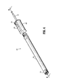
FIG. 1 is a front, perspective view of one embodiment of the presently disclosed surgical instrument including a loading unit engaged with an elongated body; -
FIG. 2 is a perspective view of the surgical instrument without the loading unit engaged with the elongated body; -
FIG. 3 is a perspective view of the loading unit; -
FIG. 4 is a perspective view of a locking mechanism of the surgical instrument; -
FIG. 5 is a perspective view of a portion of the locking mechanism ofFIG. 4 ; -
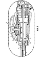
FIG. 6 is a longitudinal cross-sectional view of a portion of the surgical instrument; -
FIG. 7 is a perspective view of the elongated body portion of the surgical instrument shown with parts separated; -
FIG. 8 is a perspective view of a bushing shown inFIG. 7 ; -
FIG. 9 is a cut-away perspective view of the locking mechanism taken along line 9-9 ofFIG. 4 ; -
FIG. 10 is an enlarged view of the indicated area of detail shown inFIG. 9 ; and -
FIGS. 11 and 12 are longitudinal cross-sectional views of a portion of the locking mechanism during different stages of assembly of a first link. - Embodiments of the presently disclosed surgical instrument, and bushing for use therewith, are described in detail with reference to the drawings, wherein like reference numerals designate corresponding elements in each of the several views. As is common in the art, the term "proximal" refers to that part or component closer to the user or operator, e.g., surgeon or physician, while the term "distal" refers to that part or component farther away from the user.
- A surgical stapling instrument of the present disclosure is indicated as
reference numeral 10 inFigure 1 . The depicted surgical instrument fires staples, but it may be adapted to fire any other suitable fastener such as clips and two-part fasteners. Additionally, while the figures depict a linear fastener-applying surgical instrument, other types of endoscopic surgical instruments are encompassed by the present disclosure and are usable with the disclosedbushing 460. For example, further details of endoscopic forceps are described in commonly-ownedU.S. Patent Publication No. 2010/0179540 to Marczyk et al. , andU.S. Patent Application Serial No. 12/718,143 to Marczyk et al. , the entire contents of each of which are hereby incorporated by reference herein. In another example, further details of a circular fastener-applying surgical instrument are described in commonly-ownedU.S. Patent Publication No. 2009/0173767 to Milliman et al. , the entire contents of which are hereby incorporated by reference herein. - Generally,
surgical instrument 10 includes ahandle assembly 20 including amovable handle 22, an elongated orendoscopic portion 30 extending distally from thehandle assembly 20 and defining a longitudinal axis "A," and aloading unit 500 attachable toendoscopic portion 30, e.g., to allowsurgical instrument 10 to have greater versatility.Loading unit 500 includes aproximal portion 41 and anend effector 40, including acartridge 50 and ananvil 60, disposed adjacent theproximal portion 41. Theloading unit 500 may be configured for a single use, and/or may be configured to be used more than once. Examples of loading units for use with a surgical stapling instrument are disclosed in commonly-owned United States Patent No.5,752,644 to Bolanos et al. , the entire contents of which are hereby incorporated by reference herein. - The
movable handle 22 is actuatable (e.g., through successive strokes) to cause distal advancement of a drive rod orcontrol rod 52, such that the drive rod engages a portion of a drive assembly, which forces at least a portion of the drive assembly to translate distally. (Further details of how actuation ofmovable handle 22 causes distal advancement of the drive rod are explained inU.S. Patent No. 6,953,139 to Milliman et al. , which is hereby incorporated by reference herein.) Distal movement of the drive rod, and in particular, a dynamic clamping member engaged therewith, causes an actuation sled to move distally through thecartridge 50, which causes cam wedges of the actuation sled to sequentially engage pushers to move pushers vertically within retention slots and eject fasteners towards theanvil 60. Subsequent to the ejection of fasteners from the retention slots (and into tissue), a cutting edge of the dynamic clamping member severs the fastened tissue as the cutting edge travels distally through a slot of thecartridge 50. - With reference to
Figures 4-12 ,instrument 10 also includes alocking mechanism 400 for preventing operation ofinstrument 10 before aloading unit 500 has been engaged withelongated portion 30 ofinstrument 10.Locking mechanism 400 includes afirst link 402, abushing 460, a connecting member or connectingtube 406, and anarticulation locking member 408.Bushing 460 includes abody portion 470 and afinger 480 extending distally therefrom. First link 402 includes a plate-like member which is supported betweencontrol rod 52 and aninner body portion 232 ofelongated portion 30 of theinstrument 10 on aflat surface 53 which is ground into control rod 52 (seeFIG. 10 ). Additionally,first link 402 includes an engagement structure 414 (e.g., an opening, slot, detent, etc.) which is dimensioned to receive atongue 482 depending fromfinger 480 ofbushing 460. Bushing 460, link 402, andflat surface 53 oncontrol rod 52 function together to preventcontrol rod 52 from rotating inouter tube 230. This ensures proper rotational alignment between ahook 242 withinouter tube 230 and anotch 248 in control rod 52 (seeFIG. 10 , for example). -
Body portion 470 ofbushing 460 is disposed proximally offirst link 402 andbushing 460 is radially positioned betweenouter tube 230 andrelease link 202. Additionally,body portion 470 ofbushing 460 includes anaperture 462 extending longitudinally therethrough.Aperture 462 is dimensioned and configured to allow a portion ofcontrol rod 52 to longitudinally slide therethrough. That is, bushing 460 is slidingly positioned aboutcontrol rod 52. -
Finger 480 ofbushing 460 is configured to mechanically engagefirst link 402. In particular,tongue 482 offinger 480 is configured for reception at least partially within (or through)engagement structure 414 offirst link 402. Additionally,finger 480 is configured to flex with respect tobody portion 470. More specifically,finger 480 is able to move away from longitudinal axis "A." With particular reference toFIGS. 11 and 12 , the flexibility offinger 480 facilitates the assembly ofinstrument 10, e.g.,locking mechanism 400. That is, during assembly, proximal movement of first link 402 (shown at an angle with respect to the longitudinal axis "A") causes aproximal end 402b offirst link 402 to engagetongue 482, and in particular anangled portion 483 thereof. As shown, engagement betweenfirst link 402 andangled portion 483 oftongue 482 causesfinger 480 to flex away from the longitudinal axis "A," thus allowing or facilitating continued proximal movement offirst link 402. First link 402 is able to continue to advance proximally untilproximal end 402b offirst link 402 contacts adistal surface 474 ofbody portion 470 ofbushing 460. Here, aproximal edge 414a ofengagement structure 414 offirst link 402 has moved proximally pasttongue 482, thus allowingtongue 482 to move toward the longitudinal axis "A" (i.e., toward its biased position parallel with the longitudinal axis "A") and at least partially withinengagement structure 414. In this position,first link 402 andbushing 460 are mechanically engaged, such that longitudinal movement of either of these two components causes a corresponding longitudinal movement of the other component. Further, the engagement betweenbushing 460 andfirst link 402 prevents longitudinal translation offirst link 402 upon longitudinal translation ofcontrol rod 52. - The
proximal end 402b offirst link 402 is configured to contact (i.e., abuts or is axially movable into contact with) adistal surface 474 ofbody portion 470 ofbushing 460. Aproximal surface 476 ofbody portion 470 ofbushing 460 is configured to contact (i.e., abuts or is axially movable into contact with) adistal end 406b of a wall of connectingtube 406. Accordingly, proximal movement offirst link 402 causes corresponding proximal movement ofbushing 460 and connectingtube 406, during loading ofloading unit 500, for example. Similarly, distal movement of connectingtube 406 causes corresponding distal movement ofbushing 460 andfirst link 402, during firing of the instrument, for example. - Additionally, the transverse dimension (i.e., along the y-axis in
FIG. 8 ) of a contacting portion of theproximal surface 476 ofbody portion 470 of bushing 460 (i.e., the portion ofbushing 460 illustrated abovecontrol rod 52 inFIG. 10 ) is between about 2 to about 10 times larger than thedistal end 406b of a wall of connectingtube 406, and the transverse dimension (i.e., along the y-axis inFIG. 8 ) of a contacting portion of thedistal surface 474 ofbody portion 470 ofbushing 460 is between about 1 to about 3 times larger than theproximal end 402b offirst link 402. Thus, as can be appreciated, bushing 460 provides a robust engagement betweenfirst link 402 and connectingtube 406. It is further envisioned that a surgical instrument without bushing 460 can be modified (e.g., by shortening the length of first link 402 (e.g., adjacent itsproximal end 402b) and/or by shortening the length of connecting tube 406 (e.g., adjacent itsdistal end 406b)) to accommodate the disclosedbushing 460. - Further, with reference to
FIGS. 8 and10 ,bushing 460 includes astep 490 disposed onfinger 480. Wheninstrument 10 is assembled (e.g., afterouter tube 230 is slid over remainder of locking mechanism 400),step 490 is configured to abut or approximate an inner surface ofouter tube 230. The limited space (or lack of space) betweenstep 490 and the inner surface ofouter tube 230 limits the amount of transverse travel that is possible betweenbushing 460 andouter tube 230. Thus,step 490 helps ensurefinger 480 does not flex away fromcontrol rod 52 during use ofinstrument 10. Additionally,step 490 helps ensure engagement betweentongue 482 andengagement structure 414 of first link 302. - With particular reference to
FIG. 6 , connectingtube 406 is slidably positioned aboutcontrol rod 52 and has aproximal end 406a which abuts adistal face 408a of lockingmember 408. Lockingmember 408 is also slidably positioned aboutcontrol rod 52. When bushing 460 and connectingtube 406 are moved proximally by first link 402 (e.g., when loadingunit 500 is being loaded), lockingmember 408 is also moved proximally to allow distal translation ofcontrol rod 52. Further details of features and the operation of related surgical instruments are disclosed in commonly-owned United States Patent Application No.13/274,497 filed on October 17, 2011 - With continued reference to
Figure 6 ,articulation mechanism 300 is illustrated and is configured to articulate an articulatable loading unit. Although loading unit 500 (FIG. 1 ) is not shown including articulation features, it is envisioned thatloading unit 500 is articulatable in response to rotation of anarticulation lever 16. Alternatively,instrument 10 may be configured as a cross-compatible device that is usable with articulating loading units as well as non-articulating loading units. When used with a non-articulating loading unit,articulation assembly 300 would simply be inoperable. -
Articulation mechanism 300 includesarticulation lever 16, amechanism cover 320, biasingmembers 322, anupper clutch 324, alower clutch 326, amain shaft 328, and atranslation member 330.Lower clutch 326 is rotatably fixed and defines a central throughbore which is dimensioned to receivemain shaft 328.Upper clutch 324 is rotatably fixed tomain shaft 328 and includes a plurality of spaced projections which are received within serrations oflower clutch 326. Biasingmembers 322 urgeupper clutch 324 into engagement with lower clutch 326 to releasablysecure articulation mechanism 300 in a fixed position and, thus, to releasably secure the articulatable loading unit at a fixed angle of articulation. -
Main shaft 328 includes acam member 364, which is configured for sliding reception within a cam slot oftranslation member 330. Whenarticulation lever 16 is rotated,cam member 364 is rotated about an axis defined bymain shaft 328. Whencam member 364 is driven in rotation,translation member 330 is urged to move linearly.Translation member 330 is configured to engage an articulation link 333 (FIG. 7 ) of an articulatable loading unit such that linear movement oftranslation member 330 effects linear movement of thearticulation link 333 to effect articulation of the articulatable loading unit. - Referring to
Figures 7 and10 ,elongated body portion 30 ofinstrument 10 includes anouter tube 230 and aninner body portion 232 through whichcontrol rod 52 is inserted.Inner body 232 defines a recess 236 (FIG. 10 ) for slidably receivingrelease link 202 such that release link is slidably positioned betweenouter tube 230 andinner body portion 232. Aprojection 238 extending radially outwardly frombody 232 extends intorectangular opening 222 oftransverse extension 218 of release link 202 (FIG. 7 ). Aspring 240 is positioned withinrectangular opening 222 betweenprojection 238 and a distal end of opening 222 to urgerelease link 202 distally. -
Hook 242 is positioned betweenouter tube 230 andinner body portion 232 adjacent a rampedcam surface 220.Hook 242 includes anelongated body 244 having a transversedistal end 246. Transversedistal end 246 is positioned adjacent acutout 248 incontrol rod 52.Hook 242 is urged by a biasingmember 250 to a position in whichdistal end 246 ofhook 242 is located externally ofcutout 248. When release link 202 is moved proximally against the urging of biasing member 240 (e.g., by pulling a release button 204 (FIGS. 1 and2 ) proximally),cam surface 220 movesdistal end 246 ofhook 242 intocutout 248 ofcontrol rod 52. Ifcontrol rod 52 is not in its retracted position shown inFIG. 10 and notch 248 is not positioned to receivedistal end 246 ofhook 242,cam surface 220 will not be able to causehook 242 to move radially inwardly and thus link 202 will not be able to move proximally. Thus, aloading unit 500 cannot be removed or installed ifcontrol rod 52 is not in the retracted position. - From the foregoing and with reference to the various figure drawings, those skilled in the art will appreciate that certain modifications can also be made to the present disclosure without departing from the scope of the same. While several embodiments of the disclosure have been shown in the drawings, it is not intended that the disclosure be limited thereto, as it is intended that the disclosure be as broad in scope as the art will allow and that the specification be read likewise. Therefore, the above description should not be construed as limiting, but merely as exemplifications of particular embodiments. Those skilled in the art will envision other modifications within the scope and spirit of the claims appended hereto.
- The invention may be described by reference to the following numbered paragraphs:-
- 1. A surgical instrument, comprising:
- a handle assembly;
- an actuation member disposed in mechanical cooperation with the handle assembly;
- an elongated body portion extending distally from the handle assembly and defining a longitudinal axis, a distal portion of the elongated body portion configured to selectively engage a loading unit; and
- a locking mechanism disposed in mechanical cooperation with the actuation member, the locking mechanism configured to substantially prevent at least a partial movement of the actuation member when the elongated body portion is not engaged with a loading unit, the locking mechanism comprising:
- a link disposed at least partially within the elongated body portion and configured for mechanical engagement with a portion of a loading unit, at least a portion of the link being longitudinally translatable with respect to the elongated body portion;
- a bushing, at least a portion of the bushing disposed proximally of at least a portion of the link, at least a portion of the bushing being longitudinally translatable with respect to the elongated body portion; and
- a connecting member, at least a portion of the connecting member disposed proximally of at least a portion of the bushing, the connecting member being disposed in mechanical cooperation with the actuation member;
- 2. The surgical instrument of Paragraph 1, wherein the bushing includes a body portion and finger extending distally from the body portion, and wherein a distal face of the body portion abuts a proximal end of the link.
- 3. The surgical instrument of Paragraph 1, wherein a proximal face of the bushing abuts a distal end of the connecting member.
- 4. The surgical instrument of Paragraph 1, further comprising a control rod disposed at least partially within the elongated body portion, wherein longitudinal translation of the control rod effects a function of a loading unit when the loading unit is engaged with the elongated body portion.
- 5. The surgical instrument of Paragraph 4, wherein the control rod is longitudinally translatable with respect to the link, with respect to the bushing and with respect to the connecting member.
- 6. The surgical instrument of Paragraph 4, wherein the control rod is longitudinally translatable through an aperture in the bushing.
- 7. The surgical instrument of Paragraph 4, wherein the control rod is longitudinally translatable through the connecting member.
- 8. The surgical instrument of Paragraph 1, wherein a transverse dimension of a contacting portion of a proximal surface of the bushing is between about 2 to about 10 times larger than a distal end of a wall of the connecting tube.
- 9. The surgical instrument of Paragraph 1, wherein the bushing includes a body portion and finger extending distally from the body portion, wherein the finger includes a tongue, wherein the tongue is configured to engage an engagement structure of the link.
- 10. The surgical instrument of
Paragraph 9, wherein engagement between the tongue and the engagement structure couples the bushing and the link such that proximal and distal translation of the bushing causes corresponding proximal and distal translation of the link. - 11. The surgical instrument of
Paragraph 9, wherein a distal portion of the tongue includes an angled surface for engagement with a proximal end of link during assembly of the surgical instrument. - 12. The surgical instrument of Paragraph 11, wherein engagement between the proximal end of the link and the angled surface of the tongue during assembly of the surgical instrument causes the finger of the bushing to move away from the longitudinal axis.
- 13. The surgical instrument of Paragraph 12, wherein the position of the body portion of the bushing remains substantially unchanged during movement of the finger with respect to the longitudinal axis during assembly of the surgical instrument.
- 14. A surgical instrument, comprising:
- a handle assembly;
- an actuation member disposed in mechanical cooperation with the handle assembly;
- an elongated body portion extending distally from the handle assembly and defining a longitudinal axis;
- a loading unit including a proximal body portion and a tool assembly, the proximal body portion configured for selective engagement with the elongated body portion; and
- a locking mechanism disposed in mechanical cooperation with the actuation member, the locking mechanism configured to enable movement of the actuation member when the elongated body portion and the loading unit are engaged, the locking mechanism comprising:
- a link disposed at least partially within the elongated body portion and configured for mechanical engagement with a portion of the loading unit, at least a portion of the link being longitudinally translatable with respect to the elongated body portion;
- a bushing, at least a portion of the busing disposed proximally of at least a portion of the link, at least a portion of the bushing being longitudinally translatable with respect to the elongated body portion; and
- a connecting member, at least a portion of the connecting member disposed proximally of at least a portion of the bushing, the connecting member being disposed in mechanical cooperation with the actuation member;
- 15. The surgical instrument of Paragraph 14, wherein the bushing includes a body portion and finger extending distally from the body portion, wherein the finger includes a tongue, wherein the tongue is configured to engage an engagement structure of the link.
- 16. The surgical instrument of Paragraph 15, wherein engagement between the tongue and the engagement structure couples the bushing and the link such that proximal and distal translation of the bushing causes corresponding proximal and distal translation of the link.
- 17. The surgical instrument of Paragraph 15, wherein a distal portion of the tongue includes an angled surface for engagement with a proximal end of link during assembly of the surgical instrument.
- 18. The surgical instrument of Paragraph 17, wherein engagement between the proximal end of the link and the angled surface of the tongue during assembly of the surgical instrument causes the finger of the bushing to move away from the longitudinal axis.
- 19. The surgical instrument of Paragraph 18, wherein the position of the body portion of the bushing remains substantially unchanged during movement of the finger with respect to the longitudinal axis during assembly of the surgical instrument.
Claims (13)
- A surgical instrument, comprising:a handle assembly;an actuation member disposed in mechanical cooperation with the handle assembly;an elongated body portion extending distally from the handle assembly and defining a longitudinal axis, a distal portion of the elongated body portion configured to selectively engage a loading unit; anda locking mechanism disposed in mechanical cooperation with the actuation member, the locking mechanism configured to substantially prevent at least a partial movement of the actuation member when the elongated body portion is not engaged with a loading unit, the locking mechanism comprising:a link disposed at least partially within the elongated body portion and configured for mechanical engagement with a portion of a loading unit, at least a portion of the link being longitudinally translatable with respect to the elongated body portion;a bushing, at least a portion of the bushing disposed proximally of at least a portion of the link, at least a portion of the bushing being longitudinally translatable with respect to the elongated body portion; anda connecting member, at least a portion of the connecting member disposed proximally of at least a portion of the bushing, the connecting member being disposed in mechanical cooperation with the actuation member;wherein engagement between a loading unit and the elongated body portion causes proximal movement of the link, proximal movement of the bushing, and proximal movement of the connecting member.
- The surgical instrument of Claim 1, wherein the bushing includes a body portion and finger extending distally from the body portion, and wherein a distal face of the body portion abuts a proximal end of the link.
- The surgical instrument of Claim 1 or claim 2, wherein a proximal face of the bushing abuts a distal end of the connecting member.
- The surgical instrument of any preceding claim, further comprising a control rod disposed at least partially within the elongated body portion, wherein longitudinal translation of the control rod effects a function of a loading unit when the loading unit is engaged with the elongated body portion.
- The surgical instrument of Claim 4, wherein the control rod is longitudinally translatable with respect to the link, with respect to the bushing and with respect to the connecting member.
- The surgical instrument of Claim 4 or claim 5, wherein the control rod is longitudinally translatable through an aperture in the bushing.
- The surgical instrument of any one of claims 4 to 6, wherein the control rod is longitudinally translatable through the connecting member.
- The surgical instrument of any preceding claim, wherein a transverse dimension of a contacting portion of a proximal surface of the bushing is between about 2 to about 10 times larger than a distal end of a wall of the connecting tube.
- The surgical instrument of any preceding claim, wherein the bushing includes a body portion and finger extending distally from the body portion, wherein the finger includes a tongue, wherein the tongue is configured to engage an engagement structure of the link.
- The surgical instrument of Claim 9, wherein engagement between the tongue and the engagement structure couples the bushing and the link such that proximal and distal translation of the bushing causes corresponding proximal and distal translation of the link.
- The surgical instrument of Claim 9 or claim 10, wherein a distal portion of the tongue includes an angled surface for engagement with a proximal end of link during assembly of the surgical instrument.
- The surgical instrument of Claim 11, wherein engagement between the proximal end of the link and the angled surface of the tongue during assembly of the surgical instrument causes the finger of the bushing to move away from the longitudinal axis.
- The surgical instrument of Claim 12, wherein the position of the body portion of the bushing remains substantially unchanged during movement of the finger with respect to the longitudinal axis during assembly of the surgical instrument.
Applications Claiming Priority (2)
| Application Number | Priority Date | Filing Date | Title |
|---|---|---|---|
| US201261666028P | 2012-06-29 | 2012-06-29 | |
| US13/871,233 US9468439B2 (en) | 2012-06-29 | 2013-04-26 | Surgical instrument and bushing |
Publications (2)
| Publication Number | Publication Date |
|---|---|
| EP2679171A1 true EP2679171A1 (en) | 2014-01-01 |
| EP2679171B1 EP2679171B1 (en) | 2015-11-04 |
Family
ID=48782880
Family Applications (1)
| Application Number | Title | Priority Date | Filing Date |
|---|---|---|---|
| EP13174200.9A Active EP2679171B1 (en) | 2012-06-29 | 2013-06-28 | Surgical instrument and bushing |
Country Status (5)
| Country | Link |
|---|---|
| US (2) | US9468439B2 (en) |
| EP (1) | EP2679171B1 (en) |
| JP (1) | JP6245852B2 (en) |
| AU (1) | AU2013205793B2 (en) |
| CA (1) | CA2815624C (en) |
Families Citing this family (126)
| Publication number | Priority date | Publication date | Assignee | Title |
|---|---|---|---|---|
| US9468439B2 (en) * | 2012-06-29 | 2016-10-18 | Covidien Lp | Surgical instrument and bushing |
| CA2900521C (en) | 2013-02-07 | 2018-05-22 | Teleflex Medical Incorporated | End effector connection and actuation systems |
| CN105682567B (en) | 2013-11-04 | 2021-09-10 | 柯惠Lp公司 | Surgical fastener applying apparatus |
| AU2013403917A1 (en) | 2013-11-04 | 2016-04-28 | Covidien Lp | Surgical fastener applying apparatus |
| AU2013403915A1 (en) | 2013-11-04 | 2016-04-28 | Covidien Lp | Surgical fastener applying apparatus |
| US9707005B2 (en) | 2014-02-14 | 2017-07-18 | Ethicon Llc | Lockout mechanisms for surgical devices |
| WO2015174985A1 (en) | 2014-05-15 | 2015-11-19 | Lp Covidien | Surgical fastener applying apparatus |
| WO2016127434A1 (en) * | 2015-02-15 | 2016-08-18 | Covidien Lp | Universal handle for surgical instruments |
| US10039545B2 (en) | 2015-02-23 | 2018-08-07 | Covidien Lp | Double fire stapling |
| US10130367B2 (en) | 2015-02-26 | 2018-11-20 | Covidien Lp | Surgical apparatus |
| US10085749B2 (en) | 2015-02-26 | 2018-10-02 | Covidien Lp | Surgical apparatus with conductor strain relief |
| US10463368B2 (en) | 2015-04-10 | 2019-11-05 | Covidien Lp | Endoscopic stapler |
| US10172615B2 (en) | 2015-05-27 | 2019-01-08 | Covidien Lp | Multi-fire push rod stapling device |
| US10349941B2 (en) | 2015-05-27 | 2019-07-16 | Covidien Lp | Multi-fire lead screw stapling device |
| US10064622B2 (en) | 2015-07-29 | 2018-09-04 | Covidien Lp | Surgical stapling loading unit with stroke counter and lockout |
| US10045782B2 (en) | 2015-07-30 | 2018-08-14 | Covidien Lp | Surgical stapling loading unit with stroke counter and lockout |
| US10213204B2 (en) | 2015-10-02 | 2019-02-26 | Covidien Lp | Micro surgical instrument and loading unit for use therewith |
| US10772632B2 (en) | 2015-10-28 | 2020-09-15 | Covidien Lp | Surgical stapling device with triple leg staples |
| US10595864B2 (en) | 2015-11-24 | 2020-03-24 | Covidien Lp | Adapter assembly for interconnecting electromechanical surgical devices and surgical loading units, and surgical systems thereof |
| US10111660B2 (en) | 2015-12-03 | 2018-10-30 | Covidien Lp | Surgical stapler flexible distal tip |
| US10966717B2 (en) | 2016-01-07 | 2021-04-06 | Covidien Lp | Surgical fastener apparatus |
| US10660623B2 (en) | 2016-01-15 | 2020-05-26 | Covidien Lp | Centering mechanism for articulation joint |
| US10349937B2 (en) | 2016-02-10 | 2019-07-16 | Covidien Lp | Surgical stapler with articulation locking mechanism |
| US10420559B2 (en) | 2016-02-11 | 2019-09-24 | Covidien Lp | Surgical stapler with small diameter endoscopic portion |
| US10561419B2 (en) | 2016-05-04 | 2020-02-18 | Covidien Lp | Powered end effector assembly with pivotable channel |
| US11065022B2 (en) | 2016-05-17 | 2021-07-20 | Covidien Lp | Cutting member for a surgical instrument |
| US11642126B2 (en) | 2016-11-04 | 2023-05-09 | Covidien Lp | Surgical stapling apparatus with tissue pockets |
| US10631857B2 (en) | 2016-11-04 | 2020-04-28 | Covidien Lp | Loading unit for surgical instruments with low profile pushers |
| US10492784B2 (en) | 2016-11-08 | 2019-12-03 | Covidien Lp | Surgical tool assembly with compact firing assembly |
| US10463371B2 (en) | 2016-11-29 | 2019-11-05 | Covidien Lp | Reload assembly with spent reload indicator |
| US10709901B2 (en) | 2017-01-05 | 2020-07-14 | Covidien Lp | Implantable fasteners, applicators, and methods for brachytherapy |
| US10952767B2 (en) | 2017-02-06 | 2021-03-23 | Covidien Lp | Connector clip for securing an introducer to a surgical fastener applying apparatus |
| US20180235618A1 (en) | 2017-02-22 | 2018-08-23 | Covidien Lp | Loading unit for surgical instruments with low profile pushers |
| US10849621B2 (en) | 2017-02-23 | 2020-12-01 | Covidien Lp | Surgical stapler with small diameter endoscopic portion |
| US11350915B2 (en) | 2017-02-23 | 2022-06-07 | Covidien Lp | Surgical stapler with small diameter endoscopic portion |
| US10299790B2 (en) | 2017-03-03 | 2019-05-28 | Covidien Lp | Adapter with centering mechanism for articulation joint |
| US10660641B2 (en) | 2017-03-16 | 2020-05-26 | Covidien Lp | Adapter with centering mechanism for articulation joint |
| US10603035B2 (en) | 2017-05-02 | 2020-03-31 | Covidien Lp | Surgical loading unit including an articulating end effector |
| US11324502B2 (en) | 2017-05-02 | 2022-05-10 | Covidien Lp | Surgical loading unit including an articulating end effector |
| US10524784B2 (en) | 2017-05-05 | 2020-01-07 | Covidien Lp | Surgical staples with expandable backspan |
| US10390826B2 (en) | 2017-05-08 | 2019-08-27 | Covidien Lp | Surgical stapling device with elongated tool assembly and methods of use |
| US10420551B2 (en) | 2017-05-30 | 2019-09-24 | Covidien Lp | Authentication and information system for reusable surgical instruments |
| US10478185B2 (en) | 2017-06-02 | 2019-11-19 | Covidien Lp | Tool assembly with minimal dead space |
| US10624636B2 (en) | 2017-08-23 | 2020-04-21 | Covidien Lp | Surgical stapling device with floating staple cartridge |
| US10806452B2 (en) | 2017-08-24 | 2020-10-20 | Covidien Lp | Loading unit for a surgical stapling instrument |
| US10925603B2 (en) | 2017-11-14 | 2021-02-23 | Covidien Lp | Reload with articulation stabilization system |
| US10863987B2 (en) | 2017-11-16 | 2020-12-15 | Covidien Lp | Surgical instrument with imaging device |
| US10945732B2 (en) | 2018-01-17 | 2021-03-16 | Covidien Lp | Surgical stapler with self-returning assembly |
| WO2019165640A1 (en) | 2018-03-02 | 2019-09-06 | Covidien Lp | Surgical stapling instrument |
| US10849622B2 (en) | 2018-06-21 | 2020-12-01 | Covidien Lp | Articulated stapling with fire lock |
| US10736631B2 (en) | 2018-08-07 | 2020-08-11 | Covidien Lp | End effector with staple cartridge ejector |
| US10849620B2 (en) | 2018-09-14 | 2020-12-01 | Covidien Lp | Connector mechanisms for surgical stapling instruments |
| US11510669B2 (en) | 2020-09-29 | 2022-11-29 | Covidien Lp | Hand-held surgical instruments |
| US11090051B2 (en) | 2018-10-23 | 2021-08-17 | Covidien Lp | Surgical stapling device with floating staple cartridge |
| US11197673B2 (en) | 2018-10-30 | 2021-12-14 | Covidien Lp | Surgical stapling instruments and end effector assemblies thereof |
| US10912563B2 (en) | 2019-01-02 | 2021-02-09 | Covidien Lp | Stapling device including tool assembly stabilizing member |
| US11344297B2 (en) | 2019-02-28 | 2022-05-31 | Covidien Lp | Surgical stapling device with independently movable jaws |
| US11259808B2 (en) | 2019-03-13 | 2022-03-01 | Covidien Lp | Tool assemblies with a gap locking member |
| US11284892B2 (en) | 2019-04-01 | 2022-03-29 | Covidien Lp | Loading unit and adapter with modified coupling assembly |
| US11284893B2 (en) | 2019-04-02 | 2022-03-29 | Covidien Lp | Stapling device with articulating tool assembly |
| US11241228B2 (en) | 2019-04-05 | 2022-02-08 | Covidien Lp | Surgical instrument including an adapter assembly and an articulating surgical loading unit |
| US11224424B2 (en) | 2019-08-02 | 2022-01-18 | Covidien Lp | Linear stapling device with vertically movable knife |
| US11406385B2 (en) | 2019-10-11 | 2022-08-09 | Covidien Lp | Stapling device with a gap locking member |
| US11123068B2 (en) | 2019-11-08 | 2021-09-21 | Covidien Lp | Surgical staple cartridge |
| US11707274B2 (en) | 2019-12-06 | 2023-07-25 | Covidien Lp | Articulating mechanism for surgical instrument |
| US11109862B2 (en) | 2019-12-12 | 2021-09-07 | Covidien Lp | Surgical stapling device with flexible shaft |
| US11737747B2 (en) | 2019-12-17 | 2023-08-29 | Covidien Lp | Hand-held surgical instruments |
| US11452524B2 (en) | 2020-01-31 | 2022-09-27 | Covidien Lp | Surgical stapling device with lockout |
| US11278282B2 (en) | 2020-01-31 | 2022-03-22 | Covidien Lp | Stapling device with selective cutting |
| EP4103070A4 (en) | 2020-02-14 | 2023-11-08 | Covidien LP | Cartridge holder for surgical staples and having ridges in peripheral walls for gripping tissue |
| US11344301B2 (en) | 2020-03-02 | 2022-05-31 | Covidien Lp | Surgical stapling device with replaceable reload assembly |
| US11344302B2 (en) | 2020-03-05 | 2022-05-31 | Covidien Lp | Articulation mechanism for surgical stapling device |
| US11707278B2 (en) | 2020-03-06 | 2023-07-25 | Covidien Lp | Surgical stapler tool assembly to minimize bleeding |
| US11246593B2 (en) | 2020-03-06 | 2022-02-15 | Covidien Lp | Staple cartridge |
| US11317911B2 (en) | 2020-03-10 | 2022-05-03 | Covidien Lp | Tool assembly with replaceable cartridge assembly |
| US11357505B2 (en) | 2020-03-10 | 2022-06-14 | Covidien Lp | Surgical stapling apparatus with firing lockout mechanism |
| US11406383B2 (en) | 2020-03-17 | 2022-08-09 | Covidien Lp | Fire assisted powered EGIA handle |
| US11331098B2 (en) | 2020-04-01 | 2022-05-17 | Covidien Lp | Sled detection device |
| US11426159B2 (en) | 2020-04-01 | 2022-08-30 | Covidien Lp | Sled detection device |
| US11504117B2 (en) | 2020-04-02 | 2022-11-22 | Covidien Lp | Hand-held surgical instruments |
| US11937794B2 (en) | 2020-05-11 | 2024-03-26 | Covidien Lp | Powered handle assembly for surgical devices |
| US11191537B1 (en) | 2020-05-12 | 2021-12-07 | Covidien Lp | Stapling device with continuously parallel jaws |
| US11406387B2 (en) | 2020-05-12 | 2022-08-09 | Covidien Lp | Surgical stapling device with replaceable staple cartridge |
| US11534167B2 (en) | 2020-05-28 | 2022-12-27 | Covidien Lp | Electrotaxis-conducive stapling |
| US11191538B1 (en) | 2020-06-08 | 2021-12-07 | Covidien Lp | Surgical stapling device with parallel jaw closure |
| US11844517B2 (en) | 2020-06-25 | 2023-12-19 | Covidien Lp | Linear stapling device with continuously parallel jaws |
| US11324500B2 (en) | 2020-06-30 | 2022-05-10 | Covidien Lp | Surgical stapling device |
| US11517305B2 (en) | 2020-07-09 | 2022-12-06 | Covidien Lp | Contoured staple pusher |
| US11446028B2 (en) | 2020-07-09 | 2022-09-20 | Covidien Lp | Tool assembly with pivotable clamping beam |
| US11266402B2 (en) | 2020-07-30 | 2022-03-08 | Covidien Lp | Sensing curved tip for surgical stapling instruments |
| US11439392B2 (en) | 2020-08-03 | 2022-09-13 | Covidien Lp | Surgical stapling device and fastener for pathological exam |
| US11395654B2 (en) * | 2020-08-07 | 2022-07-26 | Covidien Lp | Surgical stapling device with articulation braking assembly |
| US11602342B2 (en) | 2020-08-27 | 2023-03-14 | Covidien Lp | Surgical stapling device with laser probe |
| US11678878B2 (en) | 2020-09-16 | 2023-06-20 | Covidien Lp | Articulation mechanism for surgical stapling device |
| US11660092B2 (en) | 2020-09-29 | 2023-05-30 | Covidien Lp | Adapter for securing loading units to handle assemblies of surgical stapling instruments |
| US11406384B2 (en) | 2020-10-05 | 2022-08-09 | Covidien Lp | Stapling device with drive assembly stop member |
| US11576674B2 (en) | 2020-10-06 | 2023-02-14 | Covidien Lp | Surgical stapling device with articulation lock assembly |
| US11890007B2 (en) | 2020-11-18 | 2024-02-06 | Covidien Lp | Stapling device with flex cable and tensioning mechanism |
| US11737774B2 (en) | 2020-12-04 | 2023-08-29 | Covidien Lp | Surgical instrument with articulation assembly |
| US11819200B2 (en) | 2020-12-15 | 2023-11-21 | Covidien Lp | Surgical instrument with articulation assembly |
| US11553914B2 (en) | 2020-12-22 | 2023-01-17 | Covidien Lp | Surgical stapling device with parallel jaw closure |
| US11744582B2 (en) | 2021-01-05 | 2023-09-05 | Covidien Lp | Surgical stapling device with firing lockout mechanism |
| US11759206B2 (en) | 2021-01-05 | 2023-09-19 | Covidien Lp | Surgical stapling device with firing lockout mechanism |
| US11517313B2 (en) | 2021-01-27 | 2022-12-06 | Covidien Lp | Surgical stapling device with laminated drive member |
| US11759207B2 (en) | 2021-01-27 | 2023-09-19 | Covidien Lp | Surgical stapling apparatus with adjustable height clamping member |
| US11717300B2 (en) | 2021-03-11 | 2023-08-08 | Covidien Lp | Surgical stapling apparatus with integrated visualization |
| US11497495B2 (en) | 2021-03-31 | 2022-11-15 | Covidien Lp | Continuous stapler strip for use with a surgical stapling device |
| US11666330B2 (en) | 2021-04-05 | 2023-06-06 | Covidien Lp | Surgical stapling device with lockout mechanism |
| US11576670B2 (en) | 2021-05-06 | 2023-02-14 | Covidien Lp | Surgical stapling device with optimized drive assembly |
| US11812956B2 (en) | 2021-05-18 | 2023-11-14 | Covidien Lp | Dual firing radial stapling device |
| US11696755B2 (en) | 2021-05-19 | 2023-07-11 | Covidien Lp | Surgical stapling device with reload assembly removal lockout |
| US11771423B2 (en) | 2021-05-25 | 2023-10-03 | Covidien Lp | Powered stapling device with manual retraction |
| US11510673B1 (en) | 2021-05-25 | 2022-11-29 | Covidien Lp | Powered stapling device with manual retraction |
| US11701119B2 (en) | 2021-05-26 | 2023-07-18 | Covidien Lp | Powered stapling device with rack release |
| US11576675B2 (en) | 2021-06-07 | 2023-02-14 | Covidien Lp | Staple cartridge with knife |
| US11617579B2 (en) | 2021-06-29 | 2023-04-04 | Covidien Lp | Ultra low profile surgical stapling instrument for tissue resections |
| US11707275B2 (en) | 2021-06-29 | 2023-07-25 | Covidien Lp | Asymmetrical surgical stapling device |
| US11602344B2 (en) | 2021-06-30 | 2023-03-14 | Covidien Lp | Surgical stapling apparatus with firing lockout assembly |
| US11540831B1 (en) | 2021-08-12 | 2023-01-03 | Covidien Lp | Staple cartridge with actuation sled detection |
| US11779334B2 (en) | 2021-08-19 | 2023-10-10 | Covidien Lp | Surgical stapling device including a manual retraction assembly |
| US11576671B1 (en) | 2021-08-20 | 2023-02-14 | Covidien Lp | Small diameter linear surgical stapling apparatus |
| US11707277B2 (en) | 2021-08-20 | 2023-07-25 | Covidien Lp | Articulating surgical stapling apparatus with pivotable knife bar guide assembly |
| US11864761B2 (en) | 2021-09-14 | 2024-01-09 | Covidien Lp | Surgical instrument with illumination mechanism |
| US11660094B2 (en) | 2021-09-29 | 2023-05-30 | Covidien Lp | Surgical fastening instrument with two-part surgical fasteners |
| US11653922B2 (en) | 2021-09-29 | 2023-05-23 | Covidien Lp | Surgical stapling device with firing lockout mechanism |
| US11849949B2 (en) | 2021-09-30 | 2023-12-26 | Covidien Lp | Surgical stapling device with firing lockout member |
Citations (9)
| Publication number | Priority date | Publication date | Assignee | Title |
|---|---|---|---|---|
| US5752644A (en) | 1995-07-11 | 1998-05-19 | United States Surgical Corporation | Disposable loading unit for surgical stapler |
| US6032849A (en) * | 1995-08-28 | 2000-03-07 | United States Surgical | Surgical stapler |
| WO2003030743A2 (en) * | 2001-10-05 | 2003-04-17 | Tyco Healthcare Group Lp | Surgical stapling device |
| US6953139B2 (en) | 1997-09-23 | 2005-10-11 | United States Surgical Corporation | Surgical stapling apparatus |
| US20090173767A1 (en) | 2008-01-09 | 2009-07-09 | Milliman Keith L | Raised Boss for Staple Guide |
| EP2090254A1 (en) * | 2008-02-14 | 2009-08-19 | Ethicon Endo-Surgery, Inc. | Articulatable loading units for surgical stapling and cutting instruments |
| EP2090253A2 (en) * | 2008-02-15 | 2009-08-19 | Ethicon Endo-Surgery, Inc. | Disposable loading units for a surgical cutting and stapling instrument |
| US20100179540A1 (en) | 2006-10-06 | 2010-07-15 | Stanislaw Marczyk | Endoscopic Vessel Sealer and Divider Having a Flexible Articulating Shaft |
| EP2583630A2 (en) * | 2011-10-17 | 2013-04-24 | Covidien LP | Surgical stapling apparatus |
Family Cites Families (12)
| Publication number | Priority date | Publication date | Assignee | Title |
|---|---|---|---|---|
| US7481348B2 (en) | 2006-10-06 | 2009-01-27 | Tyco Healthcare Group Lp | Surgical instrument with articulating tool assembly |
| US7819297B2 (en) | 2008-02-14 | 2010-10-26 | Ethicon Endo-Surgery, Inc. | Surgical stapling apparatus with reprocessible handle assembly |
| US7819298B2 (en) | 2008-02-14 | 2010-10-26 | Ethicon Endo-Surgery, Inc. | Surgical stapling apparatus with control features operable with one hand |
| US7861906B2 (en) | 2008-02-14 | 2011-01-04 | Ethicon Endo-Surgery, Inc. | Surgical stapling apparatus with articulatable components |
| US7866527B2 (en) | 2008-02-14 | 2011-01-11 | Ethicon Endo-Surgery, Inc. | Surgical stapling apparatus with interlockable firing system |
| US7819296B2 (en) | 2008-02-14 | 2010-10-26 | Ethicon Endo-Surgery, Inc. | Surgical stapling apparatus with retractable firing systems |
| US7959051B2 (en) | 2008-02-15 | 2011-06-14 | Ethicon Endo-Surgery, Inc. | Closure systems for a surgical cutting and stapling instrument |
| US7980443B2 (en) | 2008-02-15 | 2011-07-19 | Ethicon Endo-Surgery, Inc. | End effectors for a surgical cutting and stapling instrument |
| US8608044B2 (en) | 2008-02-15 | 2013-12-17 | Ethicon Endo-Surgery, Inc. | Feedback and lockout mechanism for surgical instrument |
| US20090206131A1 (en) | 2008-02-15 | 2009-08-20 | Ethicon Endo-Surgery, Inc. | End effector coupling arrangements for a surgical cutting and stapling instrument |
| US9468439B2 (en) * | 2012-06-29 | 2016-10-18 | Covidien Lp | Surgical instrument and bushing |
| US9232944B2 (en) * | 2012-06-29 | 2016-01-12 | Covidien Lp | Surgical instrument and bushing |
-
2013
- 2013-04-26 US US13/871,233 patent/US9468439B2/en active Active
- 2013-05-09 AU AU2013205793A patent/AU2013205793B2/en not_active Ceased
- 2013-05-13 CA CA2815624A patent/CA2815624C/en active Active
- 2013-06-11 JP JP2013122860A patent/JP6245852B2/en active Active
- 2013-06-28 EP EP13174200.9A patent/EP2679171B1/en active Active
-
2016
- 2016-10-18 US US15/296,477 patent/US10568623B2/en active Active
Patent Citations (9)
| Publication number | Priority date | Publication date | Assignee | Title |
|---|---|---|---|---|
| US5752644A (en) | 1995-07-11 | 1998-05-19 | United States Surgical Corporation | Disposable loading unit for surgical stapler |
| US6032849A (en) * | 1995-08-28 | 2000-03-07 | United States Surgical | Surgical stapler |
| US6953139B2 (en) | 1997-09-23 | 2005-10-11 | United States Surgical Corporation | Surgical stapling apparatus |
| WO2003030743A2 (en) * | 2001-10-05 | 2003-04-17 | Tyco Healthcare Group Lp | Surgical stapling device |
| US20100179540A1 (en) | 2006-10-06 | 2010-07-15 | Stanislaw Marczyk | Endoscopic Vessel Sealer and Divider Having a Flexible Articulating Shaft |
| US20090173767A1 (en) | 2008-01-09 | 2009-07-09 | Milliman Keith L | Raised Boss for Staple Guide |
| EP2090254A1 (en) * | 2008-02-14 | 2009-08-19 | Ethicon Endo-Surgery, Inc. | Articulatable loading units for surgical stapling and cutting instruments |
| EP2090253A2 (en) * | 2008-02-15 | 2009-08-19 | Ethicon Endo-Surgery, Inc. | Disposable loading units for a surgical cutting and stapling instrument |
| EP2583630A2 (en) * | 2011-10-17 | 2013-04-24 | Covidien LP | Surgical stapling apparatus |
Also Published As
| Publication number | Publication date |
|---|---|
| AU2013205793B2 (en) | 2017-06-08 |
| EP2679171B1 (en) | 2015-11-04 |
| JP6245852B2 (en) | 2017-12-13 |
| US9468439B2 (en) | 2016-10-18 |
| CA2815624A1 (en) | 2013-12-29 |
| CA2815624C (en) | 2020-04-07 |
| US20140001232A1 (en) | 2014-01-02 |
| JP2014008403A (en) | 2014-01-20 |
| US20170035416A1 (en) | 2017-02-09 |
| AU2013205793A1 (en) | 2014-01-16 |
| US10568623B2 (en) | 2020-02-25 |
Similar Documents
| Publication | Publication Date | Title |
|---|---|---|
| US10568623B2 (en) | Surgical instrument and bushing | |
| US9232944B2 (en) | Surgical instrument and bushing | |
| US11375998B2 (en) | Tissue stop for surgical instrument | |
| CN107049397B (en) | Surgical stapler with small-diameter endoscope part | |
| CN107049394B (en) | Microsurgical instrument and loading unit for use therewith | |
| US8348124B2 (en) | Knife bar with geared overdrive | |
| US10034666B2 (en) | Tissue stop for surgical instrument | |
| US7172104B2 (en) | Surgical stapling apparatus | |
| US8186558B2 (en) | Locking mechanism for use with loading units | |
| US7097089B2 (en) | Surgical stapling apparatus with locking mechanism | |
| EP2389876A1 (en) | Tissue stop for surgical instrument | |
| EP3858259B1 (en) | Stapling device with selective cutting |
Legal Events
| Date | Code | Title | Description |
|---|---|---|---|
| PUAI | Public reference made under article 153(3) epc to a published international application that has entered the european phase |
Free format text: ORIGINAL CODE: 0009012 |
|
| AK | Designated contracting states |
Kind code of ref document: A1 Designated state(s): AL AT BE BG CH CY CZ DE DK EE ES FI FR GB GR HR HU IE IS IT LI LT LU LV MC MK MT NL NO PL PT RO RS SE SI SK SM TR |
|
| AX | Request for extension of the european patent |
Extension state: BA ME |
|
| 17P | Request for examination filed |
Effective date: 20140620 |
|
| RBV | Designated contracting states (corrected) |
Designated state(s): AL AT BE BG CH CY CZ DE DK EE ES FI FR GB GR HR HU IE IS IT LI LT LU LV MC MK MT NL NO PL PT RO RS SE SI SK SM TR |
|
| 17Q | First examination report despatched |
Effective date: 20140821 |
|
| GRAP | Despatch of communication of intention to grant a patent |
Free format text: ORIGINAL CODE: EPIDOSNIGR1 |
|
| INTG | Intention to grant announced |
Effective date: 20150619 |
|
| GRAS | Grant fee paid |
Free format text: ORIGINAL CODE: EPIDOSNIGR3 |
|
| GRAA | (expected) grant |
Free format text: ORIGINAL CODE: 0009210 |
|
| AK | Designated contracting states |
Kind code of ref document: B1 Designated state(s): AL AT BE BG CH CY CZ DE DK EE ES FI FR GB GR HR HU IE IS IT LI LT LU LV MC MK MT NL NO PL PT RO RS SE SI SK SM TR |
|
| REG | Reference to a national code |
Ref country code: GB Ref legal event code: FG4D |
|
| REG | Reference to a national code |
Ref country code: CH Ref legal event code: EP |
|
| REG | Reference to a national code |
Ref country code: AT Ref legal event code: REF Ref document number: 758629 Country of ref document: AT Kind code of ref document: T Effective date: 20151115 |
|
| REG | Reference to a national code |
Ref country code: IE Ref legal event code: FG4D |
|
| REG | Reference to a national code |
Ref country code: DE Ref legal event code: R096 Ref document number: 602013003720 Country of ref document: DE |
|
| REG | Reference to a national code |
Ref country code: NL Ref legal event code: MP Effective date: 20151104 |
|
| REG | Reference to a national code |
Ref country code: LT Ref legal event code: MG4D |
|
| REG | Reference to a national code |
Ref country code: AT Ref legal event code: MK05 Ref document number: 758629 Country of ref document: AT Kind code of ref document: T Effective date: 20151104 |
|
| PG25 | Lapsed in a contracting state [announced via postgrant information from national office to epo] |
Ref country code: LT Free format text: LAPSE BECAUSE OF FAILURE TO SUBMIT A TRANSLATION OF THE DESCRIPTION OR TO PAY THE FEE WITHIN THE PRESCRIBED TIME-LIMIT Effective date: 20151104 Ref country code: NO Free format text: LAPSE BECAUSE OF FAILURE TO SUBMIT A TRANSLATION OF THE DESCRIPTION OR TO PAY THE FEE WITHIN THE PRESCRIBED TIME-LIMIT Effective date: 20160204 Ref country code: IS Free format text: LAPSE BECAUSE OF FAILURE TO SUBMIT A TRANSLATION OF THE DESCRIPTION OR TO PAY THE FEE WITHIN THE PRESCRIBED TIME-LIMIT Effective date: 20160304 Ref country code: HR Free format text: LAPSE BECAUSE OF FAILURE TO SUBMIT A TRANSLATION OF THE DESCRIPTION OR TO PAY THE FEE WITHIN THE PRESCRIBED TIME-LIMIT Effective date: 20151104 Ref country code: ES Free format text: LAPSE BECAUSE OF FAILURE TO SUBMIT A TRANSLATION OF THE DESCRIPTION OR TO PAY THE FEE WITHIN THE PRESCRIBED TIME-LIMIT Effective date: 20151104 Ref country code: IT Free format text: LAPSE BECAUSE OF FAILURE TO SUBMIT A TRANSLATION OF THE DESCRIPTION OR TO PAY THE FEE WITHIN THE PRESCRIBED TIME-LIMIT Effective date: 20151104 Ref country code: NL Free format text: LAPSE BECAUSE OF FAILURE TO SUBMIT A TRANSLATION OF THE DESCRIPTION OR TO PAY THE FEE WITHIN THE PRESCRIBED TIME-LIMIT Effective date: 20151104 |
|
| REG | Reference to a national code |
Ref country code: FR Ref legal event code: PLFP Year of fee payment: 4 |
|
| PG25 | Lapsed in a contracting state [announced via postgrant information from national office to epo] |
Ref country code: FI Free format text: LAPSE BECAUSE OF FAILURE TO SUBMIT A TRANSLATION OF THE DESCRIPTION OR TO PAY THE FEE WITHIN THE PRESCRIBED TIME-LIMIT Effective date: 20151104 Ref country code: AT Free format text: LAPSE BECAUSE OF FAILURE TO SUBMIT A TRANSLATION OF THE DESCRIPTION OR TO PAY THE FEE WITHIN THE PRESCRIBED TIME-LIMIT Effective date: 20151104 Ref country code: GR Free format text: LAPSE BECAUSE OF FAILURE TO SUBMIT A TRANSLATION OF THE DESCRIPTION OR TO PAY THE FEE WITHIN THE PRESCRIBED TIME-LIMIT Effective date: 20160205 Ref country code: LV Free format text: LAPSE BECAUSE OF FAILURE TO SUBMIT A TRANSLATION OF THE DESCRIPTION OR TO PAY THE FEE WITHIN THE PRESCRIBED TIME-LIMIT Effective date: 20151104 Ref country code: SE Free format text: LAPSE BECAUSE OF FAILURE TO SUBMIT A TRANSLATION OF THE DESCRIPTION OR TO PAY THE FEE WITHIN THE PRESCRIBED TIME-LIMIT Effective date: 20151104 Ref country code: RS Free format text: LAPSE BECAUSE OF FAILURE TO SUBMIT A TRANSLATION OF THE DESCRIPTION OR TO PAY THE FEE WITHIN THE PRESCRIBED TIME-LIMIT Effective date: 20151104 Ref country code: PL Free format text: LAPSE BECAUSE OF FAILURE TO SUBMIT A TRANSLATION OF THE DESCRIPTION OR TO PAY THE FEE WITHIN THE PRESCRIBED TIME-LIMIT Effective date: 20151104 Ref country code: PT Free format text: LAPSE BECAUSE OF FAILURE TO SUBMIT A TRANSLATION OF THE DESCRIPTION OR TO PAY THE FEE WITHIN THE PRESCRIBED TIME-LIMIT Effective date: 20160304 |
|
| PG25 | Lapsed in a contracting state [announced via postgrant information from national office to epo] |
Ref country code: CZ Free format text: LAPSE BECAUSE OF FAILURE TO SUBMIT A TRANSLATION OF THE DESCRIPTION OR TO PAY THE FEE WITHIN THE PRESCRIBED TIME-LIMIT Effective date: 20151104 |
|
| REG | Reference to a national code |
Ref country code: DE Ref legal event code: R097 Ref document number: 602013003720 Country of ref document: DE |
|
| PG25 | Lapsed in a contracting state [announced via postgrant information from national office to epo] |
Ref country code: SM Free format text: LAPSE BECAUSE OF FAILURE TO SUBMIT A TRANSLATION OF THE DESCRIPTION OR TO PAY THE FEE WITHIN THE PRESCRIBED TIME-LIMIT Effective date: 20151104 Ref country code: SK Free format text: LAPSE BECAUSE OF FAILURE TO SUBMIT A TRANSLATION OF THE DESCRIPTION OR TO PAY THE FEE WITHIN THE PRESCRIBED TIME-LIMIT Effective date: 20151104 Ref country code: RO Free format text: LAPSE BECAUSE OF FAILURE TO SUBMIT A TRANSLATION OF THE DESCRIPTION OR TO PAY THE FEE WITHIN THE PRESCRIBED TIME-LIMIT Effective date: 20151104 Ref country code: DK Free format text: LAPSE BECAUSE OF FAILURE TO SUBMIT A TRANSLATION OF THE DESCRIPTION OR TO PAY THE FEE WITHIN THE PRESCRIBED TIME-LIMIT Effective date: 20151104 Ref country code: EE Free format text: LAPSE BECAUSE OF FAILURE TO SUBMIT A TRANSLATION OF THE DESCRIPTION OR TO PAY THE FEE WITHIN THE PRESCRIBED TIME-LIMIT Effective date: 20151104 |
|
| PLBE | No opposition filed within time limit |
Free format text: ORIGINAL CODE: 0009261 |
|
| STAA | Information on the status of an ep patent application or granted ep patent |
Free format text: STATUS: NO OPPOSITION FILED WITHIN TIME LIMIT |
|
| 26N | No opposition filed |
Effective date: 20160805 |
|
| PG25 | Lapsed in a contracting state [announced via postgrant information from national office to epo] |
Ref country code: SI Free format text: LAPSE BECAUSE OF FAILURE TO SUBMIT A TRANSLATION OF THE DESCRIPTION OR TO PAY THE FEE WITHIN THE PRESCRIBED TIME-LIMIT Effective date: 20151104 |
|
| PG25 | Lapsed in a contracting state [announced via postgrant information from national office to epo] |
Ref country code: BE Free format text: LAPSE BECAUSE OF FAILURE TO SUBMIT A TRANSLATION OF THE DESCRIPTION OR TO PAY THE FEE WITHIN THE PRESCRIBED TIME-LIMIT Effective date: 20151104 |
|
| PG25 | Lapsed in a contracting state [announced via postgrant information from national office to epo] |
Ref country code: MC Free format text: LAPSE BECAUSE OF FAILURE TO SUBMIT A TRANSLATION OF THE DESCRIPTION OR TO PAY THE FEE WITHIN THE PRESCRIBED TIME-LIMIT Effective date: 20151104 |
|
| REG | Reference to a national code |
Ref country code: CH Ref legal event code: PL |
|
| PG25 | Lapsed in a contracting state [announced via postgrant information from national office to epo] |
Ref country code: LI Free format text: LAPSE BECAUSE OF NON-PAYMENT OF DUE FEES Effective date: 20160630 Ref country code: CH Free format text: LAPSE BECAUSE OF NON-PAYMENT OF DUE FEES Effective date: 20160630 |
|
| REG | Reference to a national code |
Ref country code: FR Ref legal event code: PLFP Year of fee payment: 5 |
|
| REG | Reference to a national code |
Ref country code: FR Ref legal event code: PLFP Year of fee payment: 6 |
|
| PG25 | Lapsed in a contracting state [announced via postgrant information from national office to epo] |
Ref country code: HU Free format text: LAPSE BECAUSE OF FAILURE TO SUBMIT A TRANSLATION OF THE DESCRIPTION OR TO PAY THE FEE WITHIN THE PRESCRIBED TIME-LIMIT; INVALID AB INITIO Effective date: 20130628 Ref country code: CY Free format text: LAPSE BECAUSE OF FAILURE TO SUBMIT A TRANSLATION OF THE DESCRIPTION OR TO PAY THE FEE WITHIN THE PRESCRIBED TIME-LIMIT Effective date: 20151104 |
|
| PG25 | Lapsed in a contracting state [announced via postgrant information from national office to epo] |
Ref country code: TR Free format text: LAPSE BECAUSE OF FAILURE TO SUBMIT A TRANSLATION OF THE DESCRIPTION OR TO PAY THE FEE WITHIN THE PRESCRIBED TIME-LIMIT Effective date: 20151104 Ref country code: MT Free format text: LAPSE BECAUSE OF NON-PAYMENT OF DUE FEES Effective date: 20160630 Ref country code: MK Free format text: LAPSE BECAUSE OF FAILURE TO SUBMIT A TRANSLATION OF THE DESCRIPTION OR TO PAY THE FEE WITHIN THE PRESCRIBED TIME-LIMIT Effective date: 20151104 Ref country code: LU Free format text: LAPSE BECAUSE OF NON-PAYMENT OF DUE FEES Effective date: 20160628 |
|
| PG25 | Lapsed in a contracting state [announced via postgrant information from national office to epo] |
Ref country code: BG Free format text: LAPSE BECAUSE OF FAILURE TO SUBMIT A TRANSLATION OF THE DESCRIPTION OR TO PAY THE FEE WITHIN THE PRESCRIBED TIME-LIMIT Effective date: 20151104 |
|
| PG25 | Lapsed in a contracting state [announced via postgrant information from national office to epo] |
Ref country code: AL Free format text: LAPSE BECAUSE OF FAILURE TO SUBMIT A TRANSLATION OF THE DESCRIPTION OR TO PAY THE FEE WITHIN THE PRESCRIBED TIME-LIMIT Effective date: 20151104 |
|
| PGFP | Annual fee paid to national office [announced via postgrant information from national office to epo] |
Ref country code: IE Payment date: 20230525 Year of fee payment: 11 Ref country code: FR Payment date: 20230523 Year of fee payment: 11 Ref country code: DE Payment date: 20230523 Year of fee payment: 11 |
|
| PGFP | Annual fee paid to national office [announced via postgrant information from national office to epo] |
Ref country code: GB Payment date: 20230523 Year of fee payment: 11 |