EP2687258A1 - Control device for radiation therapy device, processing method and programme for same - Google Patents
Control device for radiation therapy device, processing method and programme for same Download PDFInfo
- Publication number
- EP2687258A1 EP2687258A1 EP11861548.3A EP11861548A EP2687258A1 EP 2687258 A1 EP2687258 A1 EP 2687258A1 EP 11861548 A EP11861548 A EP 11861548A EP 2687258 A1 EP2687258 A1 EP 2687258A1
- Authority
- EP
- European Patent Office
- Prior art keywords
- luminance
- computed tomography
- pixel
- image data
- radiation
- Prior art date
- Legal status (The legal status is an assumption and is not a legal conclusion. Google has not performed a legal analysis and makes no representation as to the accuracy of the status listed.)
- Granted
Links
- 238000001959 radiotherapy Methods 0.000 title claims abstract description 81
- 238000003672 processing method Methods 0.000 title claims description 9
- 230000000875 corresponding effect Effects 0.000 claims abstract description 46
- 230000008859 change Effects 0.000 claims abstract description 40
- 238000002591 computed tomography Methods 0.000 claims abstract description 39
- 230000002596 correlated effect Effects 0.000 claims abstract description 5
- 230000005855 radiation Effects 0.000 claims description 134
- 230000000241 respiratory effect Effects 0.000 claims description 87
- 238000004364 calculation method Methods 0.000 claims description 45
- 238000001514 detection method Methods 0.000 claims description 15
- 230000001276 controlling effect Effects 0.000 claims description 5
- 238000000034 method Methods 0.000 description 104
- 230000008569 process Effects 0.000 description 87
- 230000001225 therapeutic effect Effects 0.000 description 21
- 238000010586 diagram Methods 0.000 description 13
- 238000005516 engineering process Methods 0.000 description 10
- 239000003550 marker Substances 0.000 description 10
- 230000006870 function Effects 0.000 description 6
- 230000007246 mechanism Effects 0.000 description 6
- 238000003491 array Methods 0.000 description 5
- 230000000737 periodic effect Effects 0.000 description 4
- 206010028980 Neoplasm Diseases 0.000 description 2
- 230000001154 acute effect Effects 0.000 description 2
- 230000029058 respiratory gaseous exchange Effects 0.000 description 2
- 230000008901 benefit Effects 0.000 description 1
- 238000004422 calculation algorithm Methods 0.000 description 1
- 230000015556 catabolic process Effects 0.000 description 1
- 238000004891 communication Methods 0.000 description 1
- 238000004590 computer program Methods 0.000 description 1
- 238000006731 degradation reaction Methods 0.000 description 1
- 230000006866 deterioration Effects 0.000 description 1
- 230000000694 effects Effects 0.000 description 1
- 239000000284 extract Substances 0.000 description 1
- 238000002601 radiography Methods 0.000 description 1
- 239000004065 semiconductor Substances 0.000 description 1
Images


Classifications
-
- G—PHYSICS
- G06—COMPUTING; CALCULATING OR COUNTING
- G06T—IMAGE DATA PROCESSING OR GENERATION, IN GENERAL
- G06T11/00—2D [Two Dimensional] image generation
- G06T11/003—Reconstruction from projections, e.g. tomography
-
- A—HUMAN NECESSITIES
- A61—MEDICAL OR VETERINARY SCIENCE; HYGIENE
- A61B—DIAGNOSIS; SURGERY; IDENTIFICATION
- A61B6/00—Apparatus for radiation diagnosis, e.g. combined with radiation therapy equipment
- A61B6/02—Devices for diagnosis sequentially in different planes; Stereoscopic radiation diagnosis
- A61B6/03—Computerised tomographs
- A61B6/032—Transmission computed tomography [CT]
-
- A—HUMAN NECESSITIES
- A61—MEDICAL OR VETERINARY SCIENCE; HYGIENE
- A61B—DIAGNOSIS; SURGERY; IDENTIFICATION
- A61B6/00—Apparatus for radiation diagnosis, e.g. combined with radiation therapy equipment
- A61B6/52—Devices using data or image processing specially adapted for radiation diagnosis
- A61B6/5288—Devices using data or image processing specially adapted for radiation diagnosis involving retrospective matching to a physiological signal
-
- A—HUMAN NECESSITIES
- A61—MEDICAL OR VETERINARY SCIENCE; HYGIENE
- A61B—DIAGNOSIS; SURGERY; IDENTIFICATION
- A61B6/00—Apparatus for radiation diagnosis, e.g. combined with radiation therapy equipment
- A61B6/54—Control of apparatus or devices for radiation diagnosis
- A61B6/541—Control of apparatus or devices for radiation diagnosis involving acquisition triggered by a physiological signal
-
- A—HUMAN NECESSITIES
- A61—MEDICAL OR VETERINARY SCIENCE; HYGIENE
- A61N—ELECTROTHERAPY; MAGNETOTHERAPY; RADIATION THERAPY; ULTRASOUND THERAPY
- A61N5/00—Radiation therapy
- A61N5/10—X-ray therapy; Gamma-ray therapy; Particle-irradiation therapy
- A61N5/1048—Monitoring, verifying, controlling systems and methods
- A61N5/1049—Monitoring, verifying, controlling systems and methods for verifying the position of the patient with respect to the radiation beam
- A61N2005/1061—Monitoring, verifying, controlling systems and methods for verifying the position of the patient with respect to the radiation beam using an x-ray imaging system having a separate imaging source
Landscapes
- Health & Medical Sciences (AREA)
- Engineering & Computer Science (AREA)
- Life Sciences & Earth Sciences (AREA)
- Medical Informatics (AREA)
- Biomedical Technology (AREA)
- General Health & Medical Sciences (AREA)
- Animal Behavior & Ethology (AREA)
- Veterinary Medicine (AREA)
- Nuclear Medicine, Radiotherapy & Molecular Imaging (AREA)
- Public Health (AREA)
- Pathology (AREA)
- Radiology & Medical Imaging (AREA)
- Physics & Mathematics (AREA)
- Surgery (AREA)
- Heart & Thoracic Surgery (AREA)
- Molecular Biology (AREA)
- Biophysics (AREA)
- Optics & Photonics (AREA)
- High Energy & Nuclear Physics (AREA)
- Physiology (AREA)
- Theoretical Computer Science (AREA)
- Pulmonology (AREA)
- Computer Vision & Pattern Recognition (AREA)
- General Physics & Mathematics (AREA)
- Apparatus For Radiation Diagnosis (AREA)
- Radiation-Therapy Devices (AREA)
Abstract
Description
- The present invention relates to a radiation therapy device controller that generates a CT image based on radiation radiated to a living body and tracks a position of a diseased portion in the living body, and a processing method and program for the same. Priority is claimed on Japanese Patent Application No.
2011-061021, filed March 18, 2011 - A radiation therapy device controller identifies a position in a living body to be irradiated with radiation based on a position of a diseased portion (tumor) displayed on a CT image (a computed tomography image) and irradiates the position with radiation.
- The diseased portion, such as a tumor in the living body, varies under the influence of respiration or the like. Therefore, it is necessary to identify a diseased portion whose position varies in each of CT images that are generated sequentially over time and identify the position to be irradiated with radiation based on the position of the diseased portion.
- Here, in order to improve identification accuracy of the position to be irradiated with radiation, it is necessary to accurately identify the diseased portion within the living body using the CT image. If the image quality of the CT image is improved, it is possible to accurately identify the position of the diseased portion and accurately identify the position to be irradiated with radiation by tracking the identified diseased portion. Methods of generating a CT image include an FBP method (Filtered Back Projection method).
- The FBP method is an algorithm used to generate a general CT image, and is technology of reversely projecting X-ray projection data through a fast Fourier transform to perform image reconstruction. However, although there is an advantage in that a computation time for generation of the CT image using the FBP method is short, deterioration of image quality such as generation of artifacts in the image becomes a problem particularly if the amount of projection data used for reconstruction is small. Here, CT image generation technology for resolving a problem of degradation of image quality includes a successive approximation method (an Iterative Reconstruction method).
Patent Documents 1 and 2 disclose the technology of the Iterative Reconstruction method. -
- Patent Document 1: Japanese Patent No.
3708434 - Patent Document 2: Japanese Unexamined Patent Application, First Publication No.
S60-17568 - In the technology of the successive approximation method described above, a virtual projection image is generated by projecting a CT image in the same direction as a radiation projection image, and an error is calculated between the virtual projection image and the radiation projection image generated by radiating radiation in the same direction as a projection direction of the virtual projection image. Also, the technology of the Iterative Reconstruction method is technology that reflects the error in the CT image and performs calculation of repetition of the generation of the virtual projection image and the calculation of the error between the virtual projection image and the radiation projection image to minimize the error, to thereby generate a CT image in which the error is small. However, although image quality of the CT image generated using the technology of the Iterative Reconstruction method is improved as compared to that of a CT image generated using an FBP method, in order to minimize the error between the radiation projection image and the virtual projection image for all pixel errors, a process of reflecting the error on the CT image is performed repeatedly. Accordingly, there is a problem in that generating the CT image using the Iterative Reconstruction method increases calculation time.
- An object of the present invention is to provide a radiation therapy device controller, and a processing method and program for the same that are capable of solving the problems described above.
- A first aspect of the present invention is a radiation therapy device controller for controlling a radiation therapy device that irradiates a living body arranged between a ray source and a sensor array with radiation from the ray source to treat a diseased portion of the living body, the controller including a CT image selection unit that selects, as CT image data of an update target, CT image data of a set body motion phase from a CT image data group generated for each body motion phase in advance. The CT image is generated based on information detected by the sensor array,
- The radiation therapy device controller may rotate the ray source and the sensor array to generate a radiation projection image corresponding to each of a plurality of rotation angles. As a result, the radiation therapy device controller compares: a radiation projection image generation unit that records the radiation projection image, the rotation angle when rotating the ray source and the sensor array at the time of generating the radiation projection image, and a body motion phase when generating the radiation projection image to be correlated with each other; a rotation angle detection unit that detects the rotation angle at the time of generating the radiation projection image; a reconstructed image generation unit that generates a reconstructed image when the CT image data of the update target is projected from the ray source to the sensor array at the detected rotation angle; and each pixel of the radiation projection image with each pixel of the generated reconstructed image. The radiation therapy device controller identifies: a difference information generation unit that generates difference information indicating a luminance difference for the pixels; and a pixel on a straight line connecting the ray source and a detection element of the sensor array in the CT image data of the update target. As a result, the radiation therapy device controller calculates a luminance update amount candidate value for each identified pixel based on a degree of easiness of change in the luminance value of the identified pixel and the difference information. Also, the radiation therapy device controller may include a luminance update amount calculation unit that calculates a luminance update amount of each identified pixel using the luminance update amount candidate value of each identified pixel calculated for a plurality of rotation angles corresponding to the body motion phase that is a target; and an updating unit that updates a luminance value of each corresponding pixel of the CT image data of the update target, using the luminance update amount of each identified pixel.
- The initially set CT image and a range in which the updating unit performs updating may a CT image in a range wider than a range of a CT image generated based on radiation projection images of a plurality of rotation angles.
- Further, according to a second aspect of the present invention, the luminance update amount calculation unit obtains the degree of easiness of change in the luminance value based on a difference between an initially set CT image of a body motion phase close to the body motion phase of the CT image data of the update target and an initially set CT image of another body motion phase close to the body motion phase of the initially set CT image.
- Further, according to a third aspect of the present invention, the luminance update amount calculation unit obtains the degree of easiness of change in the luminance value based on a difference between an initially set CT image of a body motion phase close to the body motion phase of the CT image data of the update target and the CT image data of the update target generated based on the radiation projection image corresponding to an arbitrary body motion phase.
- Further, according to the third aspect of the present invention, the radiation therapy device controller may include a diseased portion position tracking unit that calculates a position of the diseased portion corresponding to a measured body motion phase of the living body to track the diseased portion position using a correlation model formula showing a correlation between the body motion phase of the living body and the position of the diseased portion in the living body.
- Further, a fourth aspect of the present invention is a processing method for a radiation therapy device controller for controlling a radiation therapy device that irradiates a living body arranged between a ray source and a sensor array with radiation from the ray source to treat a diseased portion of the living body, and generating a computed tomography image (CT image) based on information detected by the sensor array. In the processing method, CT image data of a set body motion phase is selected, as CT image data of an update target, from a CT image data group generated for each body motion phase in advance, and the ray source and the sensor array are rotated to generate a radiation projection image corresponding to each of a plurality of rotation angles. Further, in the processing method, the rotation angle is correlated with a separately acquired respiratory phase, the rotation angle at the time of generating the radiation projection image is detected, and a reconstructed image when the CT image data of the update target is projected from the ray source to the sensor array at the detected rotation angle is generated. Further, in the processing method, each pixel of the identified radiation projection image is compared with each pixel of the generated reconstructed image to generate difference information indicating a luminance difference for the pixels, and a pixel on a straight line connecting the ray source and the sensor array is identified in the CT image data of the update target. A luminance update amount candidate value is calculated for each identified pixel based on a degree of easiness of change in the luminance value of the identified pixel and the difference information. Also, a luminance update amount of each identified pixel is calculated using the luminance update amount candidate value of each identified pixel calculated for a plurality of rotation angles corresponding to the body motion phase that is a target. A luminance value of each corresponding pixel of the CT image data of the update target is updated using the luminance update amount of each identified pixel.
- Further, a fifth aspect of the present invention is a program that controls a radiation therapy device that irradiates a living body arranged between a ray source and a sensor array with radiation from the ray source to treat a diseased portion of the living body. This program causes a computer of a radiation therapy device controller for generating a computed tomography image (CT image) based on information detected by the sensor array to function as: a CT image selection device that selects, as CT image data of an update target, CT image data of a set body motion phase from a CT image data group generated for each body motion phase in advance; a radiation projection image generation device that rotates the ray source and the sensor array to generate a radiation projection image corresponding to each of a plurality of rotation angles, and correlates the rotation angle with a separately acquired respiratory phase; a rotation angle detection device that detects the rotation angle at the time of generating the radiation projection image; and a reconstructed image generation device that generates a reconstructed image when the CT image data of the update target is projected from the ray source to the sensor array at the detected rotation angle. Further, this program causes the computer to function as: a difference information generation device that compares each pixel of the radiation projection image with each pixel of the generated reconstructed image to generate difference information indicating a luminance difference for the pixels; a luminance update amount calculation device that identifies, in the CT image data of the update target, a pixel on a straight line connecting the ray source and the sensor array, calculates a luminance update amount candidate value for each identified pixel based on a degree of easiness of change in the luminance value of the identified pixel and the difference information, and calculates a luminance update amount of each identified pixel using the luminance update amount candidate value of each identified pixel calculated for a plurality of rotation angles corresponding to the body motion phase that is a target; and an updating device that updates a luminance value of each corresponding pixel of the CT image data of the update target, using the luminance update amount of each identified pixel.
- According to the present invention, since the process of updating the data using the CT image data group (the initially set CT image data group) created in advance and recorded in the database is performed, it is possible to obtain a high-quality CT image in a short time by performing only the updating process using the newly generated radiation projection image.
- Further, the luminance update amount is calculated only for each pixel whose luminance update amount candidate value has been calculated, the process of updating the CT image using the luminance update amount is performed, and the updating process is not performed on a pixel whose luminance update amount candidate value has not been calculated. Accordingly, it is possible to shorten a time to complete the updating process.
-
-
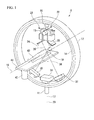
Fig. 1 is a diagram illustrating a configuration of a radiation therapy device. -
Fig. 2 is a block diagram illustrating a configuration of a radiation therapy device controller. -
Fig. 3 is a diagram illustrating a process flow of the radiation therapy device controller. -
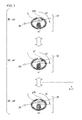
Fig. 4 is a diagram illustrating an overview of a difference information generation process. -
Fig. 5 is a diagram illustrating an overview of a process of calculating a change amount S1(t) of a pixel. -
Fig. 6 is a diagram illustrating an overview of a process of calculating a luminance update amount. -
Fig. 7 is a diagram illustrating a difference with a range of a CT image in which a conventional updating process can be performed. - Hereinafter, a radiation therapy device controller, and a radiation therapy device controlled by the radiation therapy device controller according to an embodiment of the present invention will be described.
- An embodiment of the present invention is assumed to create a CT image for each body motion phase of a periodic body motion such as respiration or heartbeat. However, a description in which only a respiratory phase is a target of the body motion will be given hereinafter for simplification.
- In the present embodiment, a method of generating an initially set CT image data group generated for each respiratory phase in advance and a reconstructed CT image data group for each respiratory phase based on a radiation projection image generated at a time point at which a CT image is to be generated is shown.
- First, an overview of the radiation therapy device that is a control target will be described.
Fig. 1 shows a radiation therapy device. - As shown in
Fig. 1 , aradiation therapy device 3 includes aswivel driving device 11, anO ring 12, a travelinggantry 14, ahead swing mechanism 15, and a therapeuticradiation radiating device 16. Theswivel driving device 11 supports theO ring 12 against a base to be rotatable around arotation axis 17, and rotates theO ring 12 around therotation axis 17 under control of the radiationtherapy device controller 1. Therotation axis 17 is parallel to a vertical direction. TheO ring 12 is formed in a ring shape around arotation axis 18 and supports the travelinggantry 14 to be rotatable around therotation axis 18. Therotation axis 18 is perpendicular to the vertical direction and passes through anisocenter 19 included in therotation axis 17. Further, therotation axis 18 is fixed with respect to theO ring 12. That is, therotation axis 18 is rotated around therotation axis 17 together with theO ring 12. The travelinggantry 14 is formed in a ring shape around therotation axis 18, and arranged to be concentric with the ring of theO ring 12. Further, theradiation therapy device 3 includes a traveling driving device, which is not shown. The traveling driving device rotates the travelinggantry 14 around therotation axis 18 under control of the radiationtherapy device controller 1. - The therapeutic
radiation radiating device 16 is arranged at an inward side of the travelinggantry 14. The therapeuticradiation radiating device 16 radiatestherapeutic radiation 23 under control of the radiationtherapy device controller 1. - The
head swing mechanism 15 is fixed to an inward side of the ring of the travelinggantry 14 and supports therapeuticradiation radiating device 16 against the travelinggantry 14. Thehead swing mechanism 15 has apan axis 21 and atilt axis 22. Thepan axis 21 is fixed to the travelinggantry 14 and is parallel to therotation axis 18 without intersecting therotation axis 18. Thetilt axis 22 is fixed to the travelinggantry 14 and orthogonal to thepan axis 21. Thehead swing mechanism 15 rotates the therapeuticradiation radiating device 16 around thepan axis 21 and rotates the therapeuticradiation radiating device 16 around thetilt axis 22 under control of the radiationtherapy device controller 1. - As the therapeutic
radiation radiating device 16 is supported by the travelinggantry 14 as described above, thetherapeutic radiation 23 always substantially passes through theisocenter 19 even when theO ring 12 is rotated by theswivel driving device 11 and the travelinggantry 14 is rotated by the traveling driving device if the therapeuticradiation radiating device 16 is first adjusted to be directed to theisocenter 19 by thehead swing mechanism 15. That is, thetherapeutic radiation 23 can be radiated from an arbitrary direction to theisocenter 19 by performing the traveling and the swivel. Further, since the therapeuticradiation radiating device 16 or the like is a heavy object, there are cases in which the O ring itself is mechanically deformed according to traveling and the swivel. Also, there are cases in which the diseased portion does not necessarily match the isocenter. In this case, the therapeuticradiation radiating device 16 may be adjusted to be directed to theisocenter 19 or the diseased portion by thehead swing mechanism 15 again, subsequent to setting of the traveling and the swivel. - Further, the
radiation therapy device 3 includes a plurality of imager systems. That is, theradiation therapy device 3 includesdiagnostic X-ray sources sensor arrays - The
diagnostic X-ray source 24 is supported by the travelinggantry 14. Thediagnostic X-ray source 24 is arranged at the inward side of the ring of the travelinggantry 14 and arranged in such a position that an angle formed by a line segment connecting theisocenter 19 and thediagnostic X-ray source 24 and a line segment connecting theisocenter 19 and the therapeuticradiation radiating device 16 is an acute angle. Thediagnostic X-ray source 24 radiates adiagnostic X-ray 35 toward theisocenter 19 under control of the radiationtherapy device controller 1. Thediagnostic X-ray 35 is a cone-beam in a cone shape radiated from one point of thediagnostic X-ray source 24 and having the point as a vertex. Thediagnostic X-ray source 25 is supported by the travelinggantry 14. Thediagnostic X-ray source 25 is arranged at the inward side of the ring of the travelinggantry 14 and arranged in such a position that an angle formed by a line segment connecting theisocenter 19 and thediagnostic X-ray source 25 and a line segment connecting theisocenter 19 and the therapeuticradiation radiating device 16 is an acute angle. Thediagnostic X-ray source 25 radiates adiagnostic X-ray 36 toward theisocenter 19 under control of the radiationtherapy device controller 1. Thediagnostic X-ray 36 is a cone-beam in a cone shape radiated from one point of thediagnostic X-ray source 25 and having the point as a vertex. - The
sensor array 32 is supported by the travelinggantry 14. Thesensor array 32 receives thediagnostic X-ray 35 that is radiated by thediagnostic X-ray source 24 and then transmitted through a subject around theisocenter 19, and generates a radiation projection image of the subject. Thesensor array 33 is supported by the travelinggantry 14. Thesensor array 33 receives thediagnostic X-ray 36 that is radiated by thediagnostic X-ray source 25 and then transmitted through the subject around theisocenter 19, and generates a radiation projection image of the subject. An FPD (Flat Panel Detector) or an X ray II (Image Intensifier) is exemplified as thesensor arrays - According to such imager systems, it is possible to generate the radiation projection image centered on the
isocenter 19 based on image signals obtained by thesensor arrays - The
radiation therapy device 3 further includes asensor array 31. Thesensor array 31 is arranged in such a manner that a line segment connecting thesensor array 31 and the therapeuticradiation radiating device 16 passes through theisocenter 19 and is fixed to the inward side of the ring of the travelinggantry 14. Thesensor array 31 receives thetherapeutic radiation 23 that is radiated by the therapeuticradiation radiating device 16 and transmitted through the subject around theisocenter 19, and generates a radiation projection image of the subject. An FPD (Flat Panel Detector) or an X ray II (Image Intensifier) is exemplified as thesensor array 31. - When the traveling
gantry 14 is caused to travel along theO ring 12, positional relationships between thediagnostic X-ray source 24 and thesensor array 32, thediagnostic X-ray source 25 and thesensor array 33, and the therapeuticradiation radiating device 16 and thesensor array 31 can be maintained during rotation around therotation axis 18 passing through theisocenter 19. A rotation angle around therotation axis 18 of the travelinggantry 14, thediagnostic X-ray sources radiation radiating device 16 and thesensor arrays 31 to 33 relative to a predetermined position is hereinafter referred to simply as a rotation angle. - Further, the
radiation therapy device 3 includes a treatment table 41 and a treatmenttable driving device 42. The treatment table 41 is used for a patient 43, which is treated, to lie on. The treatment table 41 includes a fastener, which is not shown. This fastener secures the patient to the treatment table 41 so that the patient does not move. The treatmenttable driving device 42 supports the treatment table 41 against a base and moves the treatment table 41 under control of the radiationtherapy device controller 1. - Further, the
radiation therapy device 3 includes an infrared camera, which is not shown, and detects a motion of an infrared marker attached to the living body using the infrared camera. The infrared marker performs a periodic motion in a period and a phase corresponding to a respiratory period and phase in the living body. When theradiation therapy device 3 irradiates the living body with radiation under the control of the radiationtherapy device controller 1, theradiation therapy device 3 extracts the phase in the periodic motion of the infrared marker from the detected motion of the infrared marker, and notifies the radiationtherapy device controller 1 of data of the extracted phase as information relating to the respiratory phase. Also, the radiationtherapy device controller 1 generates CT image data based on the radiation projection image according to the initially set CT image data group, the different respiratory phases, and the plurality of rotation angles. -
Fig. 2 is a block diagram illustrating a configuration of the radiation therapy device controller according to the same embodiment. - In
Fig. 2 ,reference numeral 1 indicates the radiation therapy device controller that controls theradiation therapy device 3, which irradiates a living body arranged between a ray source and a sensor array arranged in a position facing the ray source with radiation along an irradiation axis from the ray source to treat a diseased portion of the living body. Here, the ray source refers to a diagnostic X-ray source or a therapeutic radiation radiating device. As shown inFig. 2 , the radiationtherapy device controller 1 includes processing units of a CTimage selection unit 102, a radiation projectionimage generation unit 103, a rotationangle detection unit 105, a reconstructedimage generation unit 106, a differenceinformation generation unit 107, a luminance updateamount calculation unit 108, a CTimage updating unit 109, and a diseased portionposition tracking unit 110, acontrol unit 101 that controls each processing unit, and adatabase 111 that stores information used for processing in each processing unit. - An initially set CT image data group generated by radiating radiation to a living body of a person or the like that is subjected to radiation treatment has been stored in the
database 111 in advance. The initially set CT image data group is a set of initially set CT image data of successive cross sections of the living body generated in advance for each respiratory phase of the living body. Further, the initially set CT image data group may be data generated by another device in advance or may be data generated by the radiationtherapy device controller 1 in advance. - The CT
image selection unit 102 is a processing unit that selects the initially set CT image data of a set respiratory phase from the initially set CT image data group. - The radiation projection
image generation unit 103 is a processing unit that generates a radiation projection image corresponding to each of a plurality of rotation angles and correlates the rotation angle indicated by the generated radiation projection image with a separately acquired respiratory phase. - The rotation
angle detection unit 105 is a processing unit that detects a rotation angle at the time of generation of an identified radiation projection image. - The reconstructed
image generation unit 106 is a processing unit that generates a reconstructed image that is estimated to be obtainable from the sensor array (seeFig. 1 ) facing the ray source based on the initially set CT image data or reconstructed CT image data in which a luminance value of a pixel in the initially set CT image data has been updated at each rotation angle. - Hereinafter, the radiation projection image is assumed to be a radiation projection image generated by the radiation radiated toward the
sensor array 32 by thediagnostic X-ray source 24. Further, the embodiment of the present invention is similarly satisfied even when another ray source and another sensor array that face each other are used or when a plurality of sets of ray sources and sensor arrays that face each other are used. - The difference
information generation unit 107 is a processing unit that compares each pixel of the identified radiation projection image with each pixel of the generated reconstructed image to generate difference information indicating a luminance difference between the pixels. - The luminance update
amount calculation unit 108 is a processing unit that identifies, in the reconstructed CT image data, a pixel on a straight line connecting thediagnostic X-ray source 24 and the detection element of thesensor array 32 and calculates a luminance update amount of each identified pixel. - Further, the CT
image updating unit 109 is a processing unit that updates the luminance value of each corresponding pixel of the reconstructed CT image data using the luminance update amount of each identified pixel. - Here, the radiation
therapy device controller 1 compares the reconstructed CT image data after the update of the luminance value of each corresponding pixel of the reconstructed CT image data using the luminance update amount for each pixel with the reconstructed CT image data before the update of the luminance value of each corresponding pixel of the reconstructed CT image data. Also, when the luminance difference between the CT images is greater than or equal to a predetermined threshold value, the radiationtherapy device controller 1 repeats processes of the reconstructedimage generation unit 106, the differenceinformation generation unit 107, the luminance updateamount calculation unit 108, and the CTimage updating unit 109 using the reconstructed CT image after the update. The threshold value is set in consideration of a statistical variation range of the luminance value. - Further, the diseased portion
position tracking unit 110 is a processing unit that calculates a movement position of the measured diseased portion corresponding to the respiratory phase of the living body using a correlation model formula showing a correlation between the respiratory phase of the living body and a movement position of the diseased portion calculated in the reconstructed CT image data, and tracks the position of the diseased portion. There is a polynomial model formula, a non-parametric model formula or the like as a correlation model formula. - Next, a process flow of the radiation
therapy device controller 1 that controls theradiation therapy device 3 will be described step by step. - Coordinates of the initially set CT image data and the reconstructed CT image data are aligned based on a position of a spine or the like that rarely moves in a body motion prior to the present process flow.
-
Fig. 3 is a diagram illustrating a process flow of the radiation therapy device controller. - The
control unit 101 instructs theradiation therapy device 3 to capture a radiation projection image including a diseased portion position. Then, thediagnostic X-ray source 24 irradiates the living body with radiation, and the radiationtherapy device controller 1 receives a signal detected by thesensor array 32 or position data of the infrared marker acquired by an infrared sensor, which is not shown. As described above, a period and phase of a periodic motion of the infrared marker correspond to a respiratory period and phase. - Also, the radiation projection
image generation unit 103 generates a radiation projection image including the diseased portion position of the living body corresponding to a first rotation angle of rotation angles An (n = 1 ... n). The radiation projectionimage generation unit 103 records, in thedatabase 111, the generated radiation projection image in correlation with the rotation angle and the information relating to the respiratory phase extracted from the data of the phase acquired by the infrared sensor when the radiation is radiated (step S101). - While the reconstructed CT image data is created in a plurality of respiratory phases in the present process, a process in one respiratory phase (hereinafter referred to as a respiratory phase p1) will be hereinafter described.
- The
control unit 101 instructs the CTimage selection unit 102 to start the process. The CTimage selection unit 102 reads the set respiratory phase p1 from a memory. Also, the CTimage selection unit 102 selects CT image data sD1' recorded in correlation with a respiratory phase p1' closest to the set respiratory phase p1 from the initially set CT image data group recorded in thedatabase 111, and uses the CT image data sD1' as initial reconstructed CT image data kD1 (step S103). The CTimage selection unit 102 then reads the radiation projection image and the rotation angle (rotation angle A1) recorded in correlation with the respiratory phase p among combination data of (the radiation projection image, the rotation angle, and the respiratory phase) recorded in the database 111 (step S104). -
Fig. 4 is a diagram illustrating an overview of a difference information generation process. - Initially set CT image data shown in
Fig. 4 represents CT image data D1 (the reconstructed CT image data kD1 when the initially set CT image data sD1 has been updated) recorded in correlation with the one respiratory phase p1 among the CT image data included in the initially set CT image data group. Further, a radiation projection image E is a radiation projection image generated when the living body has been photographed at a rotation angle A1 in the respiratory phase p1. Hereinafter, the radiation projection image E is described as a radiation projection image (respiratory phase p1, rotation angle A1). - Next, the reconstructed
image generation unit 106 generates a reconstructed image using the reconstructed CT image data (the initially set CT image data selected by the CTimage selection unit 102 when a first updating process is performed) (step S105). In this case, if the rotation angle is A1, the reconstructedimage generation unit 106 generates the reconstructed image when the radiation from thediagnostic X-ray source 24 is assumed to be projected to a living body shown by the CT image. - A generation overview of the reconstructed image is shown in
Fig. 4 . The reconstructed image indicates, for example, a DRR (Digital Reconstructed Radiography) image. Hereinafter, the reconstructed image will be referred to as a DRR image F. - Further, the DRR image F generated in
step S 105 is described as a DRR image (respiratory phase p1, rotation angle A1). A method of generating the DRR image F is known technology. Also, when the DRR image (respiratory phase p1, rotation angle A1) is generated, the differenceinformation generation unit 107 compares pixels of the radiation projection image (respiratory phase p1, rotation angle A1) with pixels of the generated DRR image (respiratory phase p1, rotation angle A1), and generates difference information indicating a luminance difference for the pixels (difference information in the case of the respiratory phase p1 and the rotation angle A1) (step S106). - More specifically, when a luminance value of the radiation projection image (respiratory phase p1, rotation angle A1) is Ik(x, y) and a luminance value of the DRR image is Id(x, y) (x and y indicate a position indicated by an x coordinate and a y coordinate from an origin of a pixel of each image), the difference information Is(x, y) can be represented by:

That is, the difference information is information indicating a difference between the luminance values of pixels of the radiation projection image (respiratory phase p1, rotation angle A1) and the DRR image (respiratory phase p1, rotation angle A1). Here, if Is(x, y)≠0, it shows that there is a difference between information in a real living body from which the radiation projection image (respiratory phase p1, rotation angle A1) is generated and the reconstructed CT image data from which a DRR image (respiratory phase p1, rotation angle A1) is generated on the straight line L connecting the radiation detection element of thesensor array 32 corresponding to the pixel indicated by the coordinate (x, y) and thediagnostic X-ray source 24. Also, when the differenceinformation generation unit 107 generates the difference information, the differenceinformation generation unit 107 registers the difference information (respiratory phase p1, rotation angle A1) in thedatabase 111. - When the difference information (respiratory phase p1, rotation angle A1) is generated, the
control unit 101 instructs the luminance updateamount calculation unit 108 to start a process. In this case, the luminance updateamount calculation unit 108 reads the reconstructed CT image data kD1 of an update target (which is used to create the DRR image among the CT images). Further, the luminance updateamount calculation unit 108 reads the difference information (respiratory phase p1, rotation angle A1) and identifies a pixel z in which Is(x, y)≠0 in the difference information (respiratory phase p1, rotation angle A1). Next, the luminance updateamount calculation unit 108 identifies each pixel g indicating a portion estimated to be located on a straight line L connecting the radiation detection element on thesensor array 32 corresponding to the pixel z and thediagnostic X-ray source 24 in the reconstructed CT image data kD1 of the update target (which is used to create the DRR image among the CT images) (step S107). Further, the luminance updateamount calculation unit 108 reads the initially set CT image data sD1' of the respiratory phase p1' (the respiratory phase closest to the respiratory phase p1 in the initially set CT image data group described above) from thedatabase 111. The luminance updateamount calculation unit 108 also reads initially set CT image data sD2' that is at a closest phase p2' in a range of values smaller than the respiratory phase p1' indicated by the identified reconstructed CT image data D1 of an update target, from thedatabase 111. Further, the luminance updateamount calculation unit 108 reads initially set CT image data sD3' that is at a closest phase p3' in a range of values greater than the respiratory phase p1' indicated by the CT image data D1 of the update target, from thedatabase 111. As described above, the phases p2' and p3' are the closest phases in the range greater or smaller than the phase p1'. Therefore, sD2', sD1', and sD3' of the CT image are initially set CT images corresponding to three successive respiratory phases in the initially set CT image data group. -
Fig. 5 is a diagram illustrating an overview of a process of calculating a change amount S1(t) of the pixel. - The luminance update
amount calculation unit 108 calculates an absolute value d1 of a luminance difference between one pixel g1 among the pixels g of the identified initially set CT image data sD1' (respiratory phase p1') and a pixel g1a corresponding to the pixel g1 in the initially set CT image data sD2' (respiratory phase p2'), as shown in (A) and (B) ofFig. 5 . - Further, the luminance update
amount calculation unit 108 calculates an absolute value d2 of a luminance difference between the one pixel g1 of the initially set CT image data sD1' (respiratory phase p1') and a pixel g1b corresponding to the pixel g1 in the initially set CT image data sD3' (respiratory phase p3'), as shown in (A) and (C) ofFig. 5 . Further, the luminance updateamount calculation unit 108 identifies a greater value of the absolute value d1 and the absolute value d2 as the change amount S1(t) of the pixel g1 (step S108). - Here, a straight line L is L(t) = (Lx(t), Ly(t), Lz(t)), and t is defined as 0 <t <1.
- Further, the luminance value of the pixel g1 of the initially set CT image data sD1' (respiratory phase p1') is D1'(Lx(t), Ly(t), Lz(t)).
- Similarly, the luminance value of the pixel gla of the initially set CT image data sD2' (respiratory phase p2') is D2'(Lx(t), Ly(t), Lz(t)).
- Similarly, the luminance value of the pixel g1b of the initially set CT image data sD3' (respiratory phase p3') is D3'(Lx(t), Ly(t), Lz(t)).
- Then, the change amount S1(t) can be represented by the following formula (1). Here, "max" is a function taking a maximum value of an argument, and "abs" is a function taking an absolute value of an argument. S1(t) represents a degree of easiness of change in luminance value of the pixel in the reconstructed CT image data. Here, a change amount of the luminance when the respiratory phase is changed is regarded as the degree of easiness of change in luminance.
- [Formula 1]

- This is a process of calculating a first change amount S1(t). Also, the luminance update
amount calculation unit 108 performs the same calculation process in a plurality of pixels g identified as those indicating a portion estimated to be located on a straight line L connecting the radiation detection element on thesensor array 32 corresponding to the pixel z and thediagnostic X-ray source 24. Further, in order to improve resolution, it is desirable for this calculation process to be performed on all pixels. Hereinafter, the same calculation process is assumed to be performed in all the pixels. - In the above description, both the respiratory phase p2' and the respiratory phase p3' are used, but only one of the respiratory phases may be used.
- In addition, the luminance update
amount calculation unit 108 may calculate a change amount S(t) using a process of calculating a second change amount S2(t) or a process of calculating a third change amount S3(t), which will be described below, instead of the process of calculating a first change amount S1(t). - In the process of calculating a second change amount S2(t), the luminance update
amount calculation unit 108 reads the difference information and identifies a pixel in which Is(x, y) ≠ 0 in the difference information. Also, the luminance updateamount calculation unit 108 identifies each pixel g1 corresponding to a portion estimated to be located on a straight line L connecting the radiation detection element on thesensor array 32 corresponding to the pixel and thediagnostic X-ray source 24, in the reconstructed CT image data kD1 of an update target (which is used to create the DRR image among the CT images). The process up to this point is the same as the process of calculating a first change amount S1(t). Further, the luminance updateamount calculation unit 108 reads initially set CT image data sD1' of the respiratory phase p1' from thedatabase 108. Further, the luminance updateamount calculation unit 108 reads a plurality of radiation projection images, including a radiation projection image generated at a rotation angle at which the respiratory phase differs from p1, from thedatabase 111. Also, the luminance updateamount calculation unit 108 generates CT image data D4 using the plurality of radiation projection images at the different rotation angles. The process of generating the CT image using the plurality of radiation projection images at the different rotation angles is known technology. - Also, the luminance update
amount calculation unit 108 identifies an absolute value of a luminance difference between a pixel g1 of the identified initially set CT image data sD1' (respiratory phase p1') and a pixel g1c corresponding to the pixel g1 in the CT image D4 generated using the plurality of radiation projection images with the different rotation angles, as a change amount S(t) of the pixel g1. Also, if the luminance value of the pixel g1 of the initially set CT image data sD1' (respiratory phase p1') is D1'(Lx(t), Ly(t), Lz(t)) and the luminance value of the pixel g1c of the CT image D4 is D4(Lx(t), Ly(t), Lz(t)), the change amount S2(t) can be calculated by the following formula (2): - [Formula 2]

- The process of calculating a first change amount S1(t) and the process of calculating a second change amount S2(t) are first performed in the process of calculating a third change amount S3(t). Also, using results of the process of calculating a first change amount S1(t) and the process of calculating a second change amount S2(t), the change amount S3(t) of the pixel g1 is calculated by a formula:

- α and β are coefficients. For example, calculation in which α = 0.5 and β = 0.5 is performed.
-
Fig. 6 is a diagram illustrating an overview of a process of calculating a luminance update amount. - As shown in
Fig. 6(a) , if the process of calculating any one of the first to third change amounts S(t) is finished, the luminance updateamount calculation unit 108 calculates a sum (ΣS(t)) of change amounts S(t) calculated for all the pixels g. Further, the luminance updateamount calculation unit 108 calculates a ratio (S(t)÷ΣS(t)) of the change amount S(t) calculated for one pixel g1 corresponding to a certain portion on the straight line L to the sum of change amounts S(t). Also, the luminance updateamount calculation unit 108 multiplies the ratio of S(t) by the luminance difference Is indicated by the difference information calculated for the pixel z. In this way, the luminance updateamount calculation unit 108 calculates a luminance update amount candidate value that is a value obtained by distributing information of a difference represented by the luminance difference calculated for the pixel z to one pixel g1 corresponding to a portion estimated to be on the straight line L of the CT image data D1. This luminance update amount candidate value is R(x, y, z). This process is performed on all the pixels g on the straight line L (step S109). - If the processing of the luminance update amount candidate value is finished, the luminance update
amount calculation unit 108 determines whether the luminance update amount candidate value has been calculated for all radiation detection elements (pixels) on the sensor array 32 (step S110), and repeats the process of steps S 107 to S109 described above if the luminance update amount candidate value has not been calculated. - When the answer is "yes" in
step S 110, thecontrol unit 101 determines whether the process has been performed on all rotation angles recorded in thedatabase 111 in correlation with the respiratory phase p1 that is a target (step S111). If the process has not been performed on all the rotation angles recorded in thedatabase 111 in correlation with the respiratory phase p1 that is a target, thecontrol unit 101 changes the rotation angle A1, sets a next rotation angle A2, instructs to start the process of steps S 103 toS 110 described above using the radiation projection image of the rotation angle A2, and repeats the process up to the rotation angle An. Through the above process, a plurality of pieces of difference information of the respiratory phase p1 and the rotation angles A1 to An, and the luminance update amount candidate value R(x, y, z) of the pixel in the reconstructed CT image data kD1 of each combination of the respiratory phase p1 and the rotation angles A1 to An are recorded in thedatabase 111. - Next, the luminance update
amount calculation unit 108 calculates the luminance update amount of each pixel whose luminance update amount candidate value has been calculated, in the reconstructed CT image data kD1, using the luminance update amount candidate value for each pixel in the reconstructed CT image data kD1 calculated for each of the rotation angles A1 to An for the respiratory phase p 1 (step S 112). - More specifically, as shown in (b) of
Fig. 6 , the luminance updateamount calculation unit 108 calculates an average of the luminance update amount candidate value R(x, y, z) calculated for each of the rotation angles A1 to An for a pixel in the reconstructed CT image data kD1 of the respiratory phase p1, as the luminance update amount. - Alternatively, if the radiation projection image generated in step S101 for each repeated process at the rotation angles A1 to An based on the determination of step S111 is generated at a timing of a different respiratory phase, the luminance update
amount calculation unit 108 may calculate the luminance update amount by performing weighting in such a manner that a weight of the luminance update amount candidate value R(x, y, z) when the process of steps S 102 toS 109 is performed using the radiation projection image generated at a timing of the respiratory phase closest to the respiratory phase indicated by the reconstructed CT image data kD1 is greatest. For example, if the respiratory phase indicated by the reconstructed CT image data kD1 is p and the luminance update amount candidate value calculated using the radiation projection image in which the rotation angle is Ai and the respiratory phase is pi is Ri, the luminance update amount D of the pixel g(x, y, z) whose luminance update amount candidate value in the reconstructed CT image data kD1 has been calculated is calculated by: - [Formula 3]

- [Formula 4]

- The CT
image updating unit 109 adds the luminance update amount D calculated for each pixel whose luminance update amount candidate value in the reconstructed CT image data kD1 has been calculated to a value of the corresponding pixel in the reconstructed CT image data kD1 of the respiratory phase p1 that is a target to update the value of each pixel of the reconstructed CT image data kD1 and update the reconstructed CT image data into the reconstructed CT image data k+1D1 (step S113). Next, thecontrol unit 101 compares the reconstructed CT image data k+1D1 after the updating process with the reconstructed CT image data kD1 before the updating process. In this comparison process, a luminance difference between a certain pixel of the reconstructed CT image data k+1D1 after the updating process and the pixel of the reconstructed CT image data kD1 before the updating corresponding to the certain pixel is calculated for all corresponding pixels, and it is determined whether a sum thereof is less than a threshold value (step S114). Also, if the sum is less than the threshold value, it is determined that the process ends using the reconstructed CT image data D1 after the updating process. If the sum is greater than or equal to the threshold, the process from step S104 is repeated (k of kD1 is updated to k+1D1). In the repeated process, the reconstructed CT image data (k+1D1) after the updating process is used. - Further, if the sum is less than the threshold in
step S 114, it is determined whether the process of steps S 102 toS 114 has been performed on all respiratory phases pm (m = 1 ... m) that are reconstructed CT image data creation targets (step S115). If the process has not been performed, the process of the steps S101 toS 114 is performed on other respiratory phases. Accordingly, the process of updating the CT images for all the respiratory phases pm is finished. - Here, according to the process of updating the CT image described above, the process of updating the data is performed using the CT image data group (initially set CT image data group) created in advance and recorded in the
database 111. Accordingly, if the CT image data group already recorded in thedatabase 111 directly before the radiation is radiated to the diseased portion is used, it is possible to obtain a high-quality CT image in a short time by performing only the above-described updating process using the newly generated radiation projection image. Also, it is possible to irradiate a diseased portion position with the radiation with high accuracy by performing the process of tracking the diseased portion using the high-quality CT image. - Further, according to the process described above, since the luminance update amount only for each pixel whose luminance update amount candidate value has been calculated is calculated and the process of updating the CT image is performed using the luminance update amount, it is not necessary to perform the updating process on the pixel whose luminance update amount candidate value has not been calculated. Accordingly, it is possible to shorten a time to complete the updating process by pixels on which the updating process is not performed.
-
Fig. 7 is a diagram illustrating a difference with a range of a CT image on which a conventional updating process can be performed. - In a method of creating a CT image in conventional technology using an FBP method, a
circular range 71 of a CT image that can be generated by a plurality of radiation projection images is a target. Further, a dashed line inFig. 7 indicates a range that can be photographed in each sensor array (FPD). In the process of updating a high-quality CT image according to the present embodiment, since the CT image generated in advance can be selected by a user and the updating process can be performed on the entire CT image, it is possible to perform the process of updating a CT image (a rectangular CT image range 72) whose range is wider than that of the related art (creation of a high-quality CT image). - Also, the radiation
therapy device controller 1 performs the process of tracking the diseased portion using the CT image after the updating process described above, and performs radiation radiating control on the tracked diseased portion. Here, the diseased portionposition tracking unit 110 of the radiationtherapy device controller 1 inputs the information of the respiratory phase over time of the living body indicated by the infrared marker, from theradiation therapy device 3 that has detected the motion of the infrared marker attached to the living body using the infrared camera. Further, the diseased portionposition tracking unit 110 displays the CT image of each respiratory phase after the updating process on a display unit (e.g., a monitor) connected to the radiationtherapy device controller 1, based on a manipulation of the user. Also, the user selects the diseased portion position in the CT image after the updating process of each respiratory phase, and thecontrol unit 101 receives information of the diseased portion position. For example, thecontrol unit 101 receives a designation of a coordinate of the diseased portion position in the CT image for each respiratory phase as the diseased portion information. Based on the coordinate (movement phase) of the diseased portion position in the CT image for each respiratory phase, and the respiratory phase over time based on the motion of the infrared marker, the diseased portionposition tracking unit 110 generates a correlation model formula between the respiratory phase and the movement phase of the diseased portion. Also, the diseased portionposition tracking unit 110 registers the generated correlation model formula in thedatabase 111. - In the tracking process, the diseased portion
position tracking unit 110 of the radiationtherapy device controller 1 acquires the information of the respiratory phase over time indicated by the infrared marker attached to the living body from theradiation therapy device 3 and calculates the diseased portion position corresponding to the respiratory phase over time using the correlation model formula over time. Also, the diseased portionposition tracking unit 110 sequentially transmits the calculated diseased portion position to theradiation therapy device 3 over time and theradiation therapy device 3 radiates the received diseased portion position with radiation. - Through the process described above, it is possible to irradiate the diseased portion position with radiation with high accuracy by performing the tracking of the diseased portion position using the high-quality CT image after the updating process.
- In the above embodiment, the radiation projection image has been shown by the example in which the radiation projection image is created based on the ray source and the sensor array included in the radiation therapy device. However, the radiation projection image may be created, for example, by a diagnostic device (a CT or an MRI) included separately from the radiation therapy device.
- Further, the radiation therapy device controller or the radiation therapy device described above includes a computer system therein. Also, the process of each processing described above is stored in a computer-readable recording medium in the form of a program. As this program is read and executed by the computer, the processing is performed. Here, the computer-readable recording medium refers to a magnetic disk, a magneto-optical disc, a CD-ROM, a DVD-ROM, a semiconductor memory, or the like. Further, this computer program may be distributed to a computer through a communication line, and the computer receiving this distribution may execute the program.
- Further, the above program may be a program for realizing some of the above-described functions.
- Further, the program may be a program that can realize the above-described functions in combination with a program already recorded in the computer system, i.e., may be a so-called differential file (differential program).
- Since the process of updating data is performed using the CT image data group (the initially set CT image data group) recorded in the database, it is possible to obtain a high-quality CT image in a short time by performing only the updating process using the newly generated radiation projection image.
-
- 1
- radiation therapy device controller
- 3
- radiation therapy device
- 101
- control unit
- 102
- CT image selection unit
- 103
- radiation projection image generation unit
- 105
- rotation angle detection unit
- 106
- reconstructed image generation unit
- 107
- difference information generation unit
- 108
- luminance update amount calculation unit
- 109
- CT image updating unit
- 110
- diseased portion position tracking unit
- 111
- database
Claims (8)
- A radiation therapy device controller for controlling a radiation therapy device that irradiates a living body arranged between a ray source and a sensor array with radiation from the ray source to treat a diseased portion of the living body, the controller comprising:a computed tomography image selection unit that selects, as computed tomography image data of an update target, the computed tomography image data of a set body motion phase from a computed tomography image data group generated for each body motion phase in advance, whereinthe computed tomography image is generated based on information detected by the sensor array.
- The radiation therapy device controller according to Claim 1, further comprising:a radiation projection image generation unit that rotates the ray source and the sensor array to generate a radiation projection image corresponding to each of a plurality of rotation angles, and records the radiation projection image, the rotation angle when rotating the ray source and the sensor array at the time of generating the radiation projection image, and a body motion phase at the time of generating the radiation projection image to be correlated with each other;a rotation angle detection unit that detects the rotation angle at the time of generating the radiation projection image;a reconstructed image generation unit that generates a reconstructed image when the computed tomography image data of the update target is projected from the ray source to the sensor array at the detected rotation angle;a difference information generation unit that compares each pixel of the radiation projection image with each pixel of the generated reconstructed image to generate difference information indicating a luminance difference for the each pixels;a luminance update amount calculation unit that identifies a pixel on a straight line connecting the ray source and a detection element of the sensor array in the computed tomography image data of the update target, calculates a luminance update amount candidate value for each identified pixel based on a degree of easiness of change in the luminance value of the identified pixel and the difference information, and calculates a luminance update amount of each identified pixel using the luminance update amount candidate value of each identified pixel calculated for a plurality of rotation angles corresponding to the body motion phase that is a target; andan updating unit that updates a luminance value of each corresponding pixel of the computed tomography image data of the update target, using the luminance update amount of each identified pixel.
- The radiation therapy device controller according to Claim 1, wherein
the initially set computed tomography image and a range in which the updating unit performs updating are a computed tomography image in a range wider than a range of a computed tomography image generated based on radiation projection images of a plurality of rotation angles. - The radiation therapy device controller according to Claim 2 or 3, wherein
the luminance update amount calculation unit obtains the degree of easiness of change in the luminance value based on a difference between an initially set computed tomography image of a body motion phase close to the body motion phase of the computed tomography image data of the update target and an initially set computed tomography image of another body motion phase close to the body motion phase of the initially set computed tomography image. - The radiation therapy device controller according to Claim 2 or 3, wherein
the luminance update amount calculation unit obtains the degree of easiness of change in the luminance value based on a difference between an initially set computed tomography image of a body motion phase close to the body motion phase of the computed tomography image data of the update target and the computed tomography image data of the update target generated based on the radiation projection image corresponding to an arbitrary body motion phase. - The radiation therapy device controller according to Claim 5, the control device further comprising:a diseased portion position tracking unit that calculates a position of the diseased portion corresponding to a measured body motion phase of the living body to track the diseased portion position using a correlation model formula showing a correlation between the body motion phase of the living body and the position of the diseased portion in the living body.
- A processing method for a radiation therapy device controller for controlling a radiation therapy device that irradiates a living body arranged between a ray source and a sensor array with radiation from the ray source to treat a diseased portion of the living body, the processing method comprising:selecting, as computed tomography image data of an update target, the computed tomography image data of a set body motion phase from a computed tomography image data group generated for each body motion phase in advance;rotating the ray source and the sensor array to generate a radiation projection image corresponding to each of a plurality of rotation angles, and correlating the rotation angle with a separately acquired respiratory phase;detecting the rotation angle at the time of generating the radiation projection image;generating a reconstructed image when the computed tomography image data of the update target is projected from the ray source to the sensor array at the detected rotation angle;comparing each pixel of the identified radiation projection image with each pixel of the generated reconstructed image to generate difference information indicating a luminance difference for the pixels;identifying, in the computed tomography image data of the update target, a pixel on a straight line connecting the ray source and the sensor array, calculating a luminance update amount candidate value for each identified pixel based on a degree of easiness of change in the luminance value of the identified pixel and the difference information, and calculating a luminance update amount of each identified pixel using the luminance update amount candidate value of each identified pixel calculated for a plurality of rotation angles corresponding to the body motion phase that is a target; andupdating a luminance value of each corresponding pixel of the computed tomography image data of the update target, using the luminance update amount of each identified pixel, whereinthe computed tomography image is generated based on information detected by the sensor array.
- A program for causing a computer of a radiation therapy device controller for controlling a radiation therapy device that irradiates a living body arranged between a ray source and a sensor array with radiation from the ray source to treat a diseased portion of the living body, to function as:a computed tomography image selection device that selects, as computed tomography image data of an update target, the computed tomography image data of a set body motion phase from a computed tomography image data group generated for each body motion phase in advance;a radiation projection image generation device that rotates the ray source and the sensor array to generate a radiation projection image corresponding to each of a plurality of rotation angles, and correlates the rotation angle with a separately acquired respiratory phase;a rotation angle detection device that detects the rotation angle at the time of generating the radiation projection image;a reconstructed image generation device that generates a reconstructed image when the computed tomography image data of the update target is projected from the ray source to the sensor array at the detected rotation angle;a difference information generation device that compares each pixel of the radiation projection image with each pixel of the generated reconstructed image to generate difference information indicating a luminance difference for the pixels;a luminance update amount calculation device that identifies, in the computed tomography image data of the update target, a pixel on a straight line connecting the ray source and the sensor array, calculates a luminance update amount candidate value for each identified pixel based on a degree of easiness of change in the luminance value of the identified pixel and the difference information, and calculates a luminance update amount of each identified pixel using the luminance update amount candidate value of each identified pixel calculated for a plurality of rotation angles corresponding to the body motion phase that is a target; andan updating device that updates a luminance value of each corresponding pixel of the computed tomography image data of the update target, using the luminance update amount of each identified pixel, whereinthe computed tomography image is generated based on information detected by the sensor array.
Applications Claiming Priority (2)
| Application Number | Priority Date | Filing Date | Title |
|---|---|---|---|
| JP2011061021A JP5611091B2 (en) | 2011-03-18 | 2011-03-18 | Radiotherapy apparatus control apparatus, processing method thereof, and program |
| PCT/JP2011/074772 WO2012127727A1 (en) | 2011-03-18 | 2011-10-27 | Control device for radiation therapy device, processing method and programme for same |
Publications (3)
| Publication Number | Publication Date |
|---|---|
| EP2687258A1 true EP2687258A1 (en) | 2014-01-22 |
| EP2687258A4 EP2687258A4 (en) | 2014-09-10 |
| EP2687258B1 EP2687258B1 (en) | 2016-08-31 |
Family
ID=46878916
Family Applications (1)
| Application Number | Title | Priority Date | Filing Date |
|---|---|---|---|
| EP11861548.3A Active EP2687258B1 (en) | 2011-03-18 | 2011-10-27 | Control device for radiation therapy device, processing method and program for same |
Country Status (5)
| Country | Link |
|---|---|
| US (1) | US8965096B2 (en) |
| EP (1) | EP2687258B1 (en) |
| JP (1) | JP5611091B2 (en) |
| CN (1) | CN103282082B (en) |
| WO (1) | WO2012127727A1 (en) |
Families Citing this family (14)
| Publication number | Priority date | Publication date | Assignee | Title |
|---|---|---|---|---|
| JP5575022B2 (en) | 2011-03-18 | 2014-08-20 | 三菱重工業株式会社 | Radiotherapy apparatus control apparatus, processing method thereof, and program |
| WO2015127970A1 (en) * | 2014-02-26 | 2015-09-03 | Brainlab Ag | Tracking soft tissue in medical images |
| JP6547282B2 (en) * | 2014-11-28 | 2019-07-24 | 東芝エネルギーシステムズ株式会社 | MEDICAL IMAGE GENERATION APPARATUS, METHOD, AND PROGRAM |
| WO2016151888A1 (en) * | 2015-03-26 | 2016-09-29 | オリンパス株式会社 | Image processing device |
| DE102015215584B4 (en) * | 2015-08-14 | 2022-03-03 | Siemens Healthcare Gmbh | Method and system for the reconstruction of planning images |
| KR101797284B1 (en) * | 2015-09-01 | 2017-11-14 | 재단법인대구경북과학기술원 | Apparatus for irradiation |
| WO2017066248A1 (en) * | 2015-10-16 | 2017-04-20 | Varian Medical Systems, Inc. | Iterative image reconstruction in image-guided radiation therapy |
| US10065049B2 (en) | 2016-01-25 | 2018-09-04 | Accuray Incorporated | Presenting a sequence of images associated with a motion model |
| US9990711B2 (en) * | 2016-01-25 | 2018-06-05 | Accuray Incorporated | Manipulation of a respiratory model via adjustment of parameters associated with model images |
| JP6668902B2 (en) * | 2016-04-12 | 2020-03-18 | 株式会社島津製作所 | Positioning device and method of operating positioning device |
| US10434335B2 (en) * | 2017-03-30 | 2019-10-08 | Shimadzu Corporation | Positioning apparatus and method of positioning by generation of DRR image from X-ray CT image data |
| KR101876349B1 (en) * | 2017-04-20 | 2018-07-09 | 사회복지법인 삼성생명공익재단 | System and method for controlling medical treatment machine |
| JP7467203B2 (en) * | 2020-03-31 | 2024-04-15 | 株式会社日立製作所 | Radiation therapy system and method for operating a radiation therapy device |
| US11883687B2 (en) | 2020-09-08 | 2024-01-30 | Shanghai United Imaging Healthcare Co., Ltd. | X-ray imaging system for radiation therapy |
Citations (3)
| Publication number | Priority date | Publication date | Assignee | Title |
|---|---|---|---|---|
| US20060074292A1 (en) * | 2004-09-30 | 2006-04-06 | Accuray, Inc. | Dynamic tracking of moving targets |
| US20080063250A1 (en) * | 2006-09-07 | 2008-03-13 | Kabushiki Kaisha Toshiba | X-ray image diagnosis apparatus and a method for generating image data |
| US20100119032A1 (en) * | 2006-05-25 | 2010-05-13 | Di Yan | Portal and real time imaging for treatment verification |
Family Cites Families (11)
| Publication number | Priority date | Publication date | Assignee | Title |
|---|---|---|---|---|
| JPS6017568A (en) | 1983-07-11 | 1985-01-29 | Hitachi Ltd | Method and device for processing image |
| US5907594A (en) | 1997-07-01 | 1999-05-25 | Analogic Corporation | Reconstruction of volumetric images by successive approximation in cone-beam computed tomography systems |
| US8571639B2 (en) * | 2003-09-05 | 2013-10-29 | Varian Medical Systems, Inc. | Systems and methods for gating medical procedures |
| JP4064952B2 (en) * | 2004-08-12 | 2008-03-19 | 三菱重工業株式会社 | Radiotherapy apparatus and method of operating radiotherapy apparatus |
| EP1907058B1 (en) * | 2005-07-22 | 2015-06-24 | TomoTherapy, Inc. | Method of placing constraints on a deformation map and system for implementing same |
| JP4126318B2 (en) | 2006-06-23 | 2008-07-30 | 三菱重工業株式会社 | Radiotherapy apparatus control apparatus and radiotherapy apparatus control method |
| US20080037843A1 (en) * | 2006-08-11 | 2008-02-14 | Accuray Incorporated | Image segmentation for DRR generation and image registration |
| US7920670B2 (en) * | 2007-03-30 | 2011-04-05 | General Electric Company | Keyhole computed tomography |
| JP2010069086A (en) * | 2008-09-19 | 2010-04-02 | Toshiba Corp | Radiation therapy system and image display method |
| US20100158341A1 (en) * | 2008-12-18 | 2010-06-24 | Siemens Medical Solutions Usa, Inc. | System for Automatically Generating a Mask for Digital Subtraction Angiography |
| JP5575022B2 (en) | 2011-03-18 | 2014-08-20 | 三菱重工業株式会社 | Radiotherapy apparatus control apparatus, processing method thereof, and program |
-
2011
- 2011-03-18 JP JP2011061021A patent/JP5611091B2/en active Active
- 2011-10-27 CN CN201180060999.3A patent/CN103282082B/en active Active
- 2011-10-27 EP EP11861548.3A patent/EP2687258B1/en active Active
- 2011-10-27 US US13/993,944 patent/US8965096B2/en active Active
- 2011-10-27 WO PCT/JP2011/074772 patent/WO2012127727A1/en active Application Filing
Patent Citations (3)
| Publication number | Priority date | Publication date | Assignee | Title |
|---|---|---|---|---|
| US20060074292A1 (en) * | 2004-09-30 | 2006-04-06 | Accuray, Inc. | Dynamic tracking of moving targets |
| US20100119032A1 (en) * | 2006-05-25 | 2010-05-13 | Di Yan | Portal and real time imaging for treatment verification |
| US20080063250A1 (en) * | 2006-09-07 | 2008-03-13 | Kabushiki Kaisha Toshiba | X-ray image diagnosis apparatus and a method for generating image data |
Non-Patent Citations (1)
| Title |
|---|
| See also references of WO2012127727A1 * |
Also Published As
| Publication number | Publication date |
|---|---|
| JP2012196259A (en) | 2012-10-18 |
| US20130266202A1 (en) | 2013-10-10 |
| CN103282082B (en) | 2016-02-03 |
| EP2687258B1 (en) | 2016-08-31 |
| JP5611091B2 (en) | 2014-10-22 |
| WO2012127727A1 (en) | 2012-09-27 |
| EP2687258A4 (en) | 2014-09-10 |
| US8965096B2 (en) | 2015-02-24 |
| CN103282082A (en) | 2013-09-04 |
Similar Documents
| Publication | Publication Date | Title |
|---|---|---|
| EP2687258B1 (en) | Control device for radiation therapy device, processing method and program for same | |
| EP2662115B1 (en) | Control device for radiation therapy device and programme for same | |
| JP6181459B2 (en) | Radiation therapy system | |
| JP6139361B2 (en) | Medical image processing apparatus, treatment system, and medical image processing method | |
| US10143431B2 (en) | Medical image processing apparatus and method, and radiotherapeutic apparatus | |
| US20230091213A1 (en) | Field of view matching for mobile 3d imaging | |
| US9393444B2 (en) | Treatment planning device, treatment planning method, and program therefor | |
| US10631778B2 (en) | Patient setup using respiratory gated and time resolved image data | |
| EP2821101B1 (en) | Radiotherapy equipment control device, radiotherapy equipment control method, and program executed by computer for radiotherapy equipment | |
| US20120063565A1 (en) | Method for collimating to an off-center examination sub-object | |
| JP6310118B2 (en) | Image processing apparatus, treatment system, and image processing method | |
| US20230414968A1 (en) | Motion artifact reduction in computed tomography | |
| Hazelaar et al. | Verifying tumor position during stereotactic body radiation therapy delivery using (limited-arc) cone beam computed tomography imaging | |
| JP7078955B2 (en) | Treatment system, calibration method, and program | |
| Miura et al. | 4D modeling in a gimbaled linear accelerator by using gold anchor markers | |
| Blessing et al. | Automated ultrafast kilovoltage–megavoltage cone-beam CT for image guided radiotherapy of lung cancer: System description and real-time results | |
| Fan et al. | Toward quantitative intrafractional monitoring in paraspinal SBRT using a proprietary software application: clinical implementation and patient results | |
| Haga | X-Ray Image-Based Patient Positioning |
Legal Events
| Date | Code | Title | Description |
|---|---|---|---|
| PUAI | Public reference made under article 153(3) epc to a published international application that has entered the european phase |
Free format text: ORIGINAL CODE: 0009012 |
|
| 17P | Request for examination filed |
Effective date: 20130613 |
|
| AK | Designated contracting states |
Kind code of ref document: A1 Designated state(s): AL AT BE BG CH CY CZ DE DK EE ES FI FR GB GR HR HU IE IS IT LI LT LU LV MC MK MT NL NO PL PT RO RS SE SI SK SM TR |
|
| DAX | Request for extension of the european patent (deleted) | ||
| A4 | Supplementary search report drawn up and despatched |
Effective date: 20140812 |
|
| RIC1 | Information provided on ipc code assigned before grant |
Ipc: A61B 6/03 20060101ALI20140806BHEP Ipc: A61N 5/10 20060101AFI20140806BHEP Ipc: G06T 11/00 20060101ALI20140806BHEP |
|
| 17Q | First examination report despatched |
Effective date: 20150223 |
|
| GRAP | Despatch of communication of intention to grant a patent |
Free format text: ORIGINAL CODE: EPIDOSNIGR1 |
|
| INTG | Intention to grant announced |
Effective date: 20160316 |
|
| GRAS | Grant fee paid |
Free format text: ORIGINAL CODE: EPIDOSNIGR3 |
|
| GRAA | (expected) grant |
Free format text: ORIGINAL CODE: 0009210 |
|
| AK | Designated contracting states |
Kind code of ref document: B1 Designated state(s): AL AT BE BG CH CY CZ DE DK EE ES FI FR GB GR HR HU IE IS IT LI LT LU LV MC MK MT NL NO PL PT RO RS SE SI SK SM TR |
|
| REG | Reference to a national code |
Ref country code: CH Ref legal event code: EP Ref country code: GB Ref legal event code: FG4D |
|
| REG | Reference to a national code |
Ref country code: IE Ref legal event code: FG4D |
|
| REG | Reference to a national code |
Ref country code: DE Ref legal event code: R096 Ref document number: 602011029974 Country of ref document: DE |
|
| REG | Reference to a national code |
Ref country code: AT Ref legal event code: REF Ref document number: 824473 Country of ref document: AT Kind code of ref document: T Effective date: 20161015 |
|
| REG | Reference to a national code |
Ref country code: LT Ref legal event code: MG4D |
|
| REG | Reference to a national code |
Ref country code: NL Ref legal event code: MP Effective date: 20160831 |
|
| REG | Reference to a national code |
Ref country code: AT Ref legal event code: MK05 Ref document number: 824473 Country of ref document: AT Kind code of ref document: T Effective date: 20160831 |
|
| PG25 | Lapsed in a contracting state [announced via postgrant information from national office to epo] |
Ref country code: LT Free format text: LAPSE BECAUSE OF FAILURE TO SUBMIT A TRANSLATION OF THE DESCRIPTION OR TO PAY THE FEE WITHIN THE PRESCRIBED TIME-LIMIT Effective date: 20160831 Ref country code: RS Free format text: LAPSE BECAUSE OF FAILURE TO SUBMIT A TRANSLATION OF THE DESCRIPTION OR TO PAY THE FEE WITHIN THE PRESCRIBED TIME-LIMIT Effective date: 20160831 Ref country code: NO Free format text: LAPSE BECAUSE OF FAILURE TO SUBMIT A TRANSLATION OF THE DESCRIPTION OR TO PAY THE FEE WITHIN THE PRESCRIBED TIME-LIMIT Effective date: 20161130 Ref country code: HR Free format text: LAPSE BECAUSE OF FAILURE TO SUBMIT A TRANSLATION OF THE DESCRIPTION OR TO PAY THE FEE WITHIN THE PRESCRIBED TIME-LIMIT Effective date: 20160831 Ref country code: FI Free format text: LAPSE BECAUSE OF FAILURE TO SUBMIT A TRANSLATION OF THE DESCRIPTION OR TO PAY THE FEE WITHIN THE PRESCRIBED TIME-LIMIT Effective date: 20160831 |
|
| PG25 | Lapsed in a contracting state [announced via postgrant information from national office to epo] |
Ref country code: NL Free format text: LAPSE BECAUSE OF FAILURE TO SUBMIT A TRANSLATION OF THE DESCRIPTION OR TO PAY THE FEE WITHIN THE PRESCRIBED TIME-LIMIT Effective date: 20160831 Ref country code: ES Free format text: LAPSE BECAUSE OF FAILURE TO SUBMIT A TRANSLATION OF THE DESCRIPTION OR TO PAY THE FEE WITHIN THE PRESCRIBED TIME-LIMIT Effective date: 20160831 Ref country code: SE Free format text: LAPSE BECAUSE OF FAILURE TO SUBMIT A TRANSLATION OF THE DESCRIPTION OR TO PAY THE FEE WITHIN THE PRESCRIBED TIME-LIMIT Effective date: 20160831 Ref country code: BE Free format text: LAPSE BECAUSE OF NON-PAYMENT OF DUE FEES Effective date: 20161031 Ref country code: AT Free format text: LAPSE BECAUSE OF FAILURE TO SUBMIT A TRANSLATION OF THE DESCRIPTION OR TO PAY THE FEE WITHIN THE PRESCRIBED TIME-LIMIT Effective date: 20160831 Ref country code: LV Free format text: LAPSE BECAUSE OF FAILURE TO SUBMIT A TRANSLATION OF THE DESCRIPTION OR TO PAY THE FEE WITHIN THE PRESCRIBED TIME-LIMIT Effective date: 20160831 Ref country code: GR Free format text: LAPSE BECAUSE OF FAILURE TO SUBMIT A TRANSLATION OF THE DESCRIPTION OR TO PAY THE FEE WITHIN THE PRESCRIBED TIME-LIMIT Effective date: 20161201 |
|
| PG25 | Lapsed in a contracting state [announced via postgrant information from national office to epo] |
Ref country code: RO Free format text: LAPSE BECAUSE OF FAILURE TO SUBMIT A TRANSLATION OF THE DESCRIPTION OR TO PAY THE FEE WITHIN THE PRESCRIBED TIME-LIMIT Effective date: 20160831 Ref country code: EE Free format text: LAPSE BECAUSE OF FAILURE TO SUBMIT A TRANSLATION OF THE DESCRIPTION OR TO PAY THE FEE WITHIN THE PRESCRIBED TIME-LIMIT Effective date: 20160831 |
|
| PG25 | Lapsed in a contracting state [announced via postgrant information from national office to epo] |
Ref country code: BE Free format text: LAPSE BECAUSE OF FAILURE TO SUBMIT A TRANSLATION OF THE DESCRIPTION OR TO PAY THE FEE WITHIN THE PRESCRIBED TIME-LIMIT Effective date: 20160831 Ref country code: PL Free format text: LAPSE BECAUSE OF FAILURE TO SUBMIT A TRANSLATION OF THE DESCRIPTION OR TO PAY THE FEE WITHIN THE PRESCRIBED TIME-LIMIT Effective date: 20160831 Ref country code: PT Free format text: LAPSE BECAUSE OF FAILURE TO SUBMIT A TRANSLATION OF THE DESCRIPTION OR TO PAY THE FEE WITHIN THE PRESCRIBED TIME-LIMIT Effective date: 20170102 Ref country code: BG Free format text: LAPSE BECAUSE OF FAILURE TO SUBMIT A TRANSLATION OF THE DESCRIPTION OR TO PAY THE FEE WITHIN THE PRESCRIBED TIME-LIMIT Effective date: 20161130 Ref country code: SM Free format text: LAPSE BECAUSE OF FAILURE TO SUBMIT A TRANSLATION OF THE DESCRIPTION OR TO PAY THE FEE WITHIN THE PRESCRIBED TIME-LIMIT Effective date: 20160831 Ref country code: SK Free format text: LAPSE BECAUSE OF FAILURE TO SUBMIT A TRANSLATION OF THE DESCRIPTION OR TO PAY THE FEE WITHIN THE PRESCRIBED TIME-LIMIT Effective date: 20160831 Ref country code: CZ Free format text: LAPSE BECAUSE OF FAILURE TO SUBMIT A TRANSLATION OF THE DESCRIPTION OR TO PAY THE FEE WITHIN THE PRESCRIBED TIME-LIMIT Effective date: 20160831 Ref country code: DK Free format text: LAPSE BECAUSE OF FAILURE TO SUBMIT A TRANSLATION OF THE DESCRIPTION OR TO PAY THE FEE WITHIN THE PRESCRIBED TIME-LIMIT Effective date: 20160831 |
|
| REG | Reference to a national code |
Ref country code: CH Ref legal event code: PL |
|
| REG | Reference to a national code |
Ref country code: DE Ref legal event code: R097 Ref document number: 602011029974 Country of ref document: DE |
|
| PG25 | Lapsed in a contracting state [announced via postgrant information from national office to epo] |
Ref country code: IT Free format text: LAPSE BECAUSE OF FAILURE TO SUBMIT A TRANSLATION OF THE DESCRIPTION OR TO PAY THE FEE WITHIN THE PRESCRIBED TIME-LIMIT Effective date: 20160831 |
|
| PLBE | No opposition filed within time limit |
Free format text: ORIGINAL CODE: 0009261 |
|
| STAA | Information on the status of an ep patent application or granted ep patent |
Free format text: STATUS: NO OPPOSITION FILED WITHIN TIME LIMIT |
|
| REG | Reference to a national code |
Ref country code: DE Ref legal event code: R082 Ref document number: 602011029974 Country of ref document: DE Representative=s name: KOHLER SCHMID MOEBUS PATENTANWAELTE PARTNERSCH, DE Ref country code: DE Ref legal event code: R081 Ref document number: 602011029974 Country of ref document: DE Owner name: HITACHI, LTD., JP Free format text: FORMER OWNER: MITSUBISHI HEAVY INDUSTRIES, LTD., TOKYO, JP |
|
| REG | Reference to a national code |
Ref country code: IE Ref legal event code: MM4A |
|
| REG | Reference to a national code |
Ref country code: FR Ref legal event code: ST Effective date: 20170630 |
|
| PG25 | Lapsed in a contracting state [announced via postgrant information from national office to epo] |
Ref country code: LI Free format text: LAPSE BECAUSE OF NON-PAYMENT OF DUE FEES Effective date: 20161031 Ref country code: CH Free format text: LAPSE BECAUSE OF NON-PAYMENT OF DUE FEES Effective date: 20161031 Ref country code: FR Free format text: LAPSE BECAUSE OF NON-PAYMENT OF DUE FEES Effective date: 20161102 |
|
| 26N | No opposition filed |
Effective date: 20170601 |
|
| PG25 | Lapsed in a contracting state [announced via postgrant information from national office to epo] |
Ref country code: LU Free format text: LAPSE BECAUSE OF NON-PAYMENT OF DUE FEES Effective date: 20161027 Ref country code: SI Free format text: LAPSE BECAUSE OF FAILURE TO SUBMIT A TRANSLATION OF THE DESCRIPTION OR TO PAY THE FEE WITHIN THE PRESCRIBED TIME-LIMIT Effective date: 20160831 |
|
| REG | Reference to a national code |
Ref country code: GB Ref legal event code: 732E Free format text: REGISTERED BETWEEN 20170817 AND 20170823 |
|
| PG25 | Lapsed in a contracting state [announced via postgrant information from national office to epo] |
Ref country code: IE Free format text: LAPSE BECAUSE OF NON-PAYMENT OF DUE FEES Effective date: 20161027 |
|
| PG25 | Lapsed in a contracting state [announced via postgrant information from national office to epo] |
Ref country code: CY Free format text: LAPSE BECAUSE OF FAILURE TO SUBMIT A TRANSLATION OF THE DESCRIPTION OR TO PAY THE FEE WITHIN THE PRESCRIBED TIME-LIMIT Effective date: 20160831 Ref country code: HU Free format text: LAPSE BECAUSE OF FAILURE TO SUBMIT A TRANSLATION OF THE DESCRIPTION OR TO PAY THE FEE WITHIN THE PRESCRIBED TIME-LIMIT; INVALID AB INITIO Effective date: 20111027 |
|
| PG25 | Lapsed in a contracting state [announced via postgrant information from national office to epo] |
Ref country code: MT Free format text: LAPSE BECAUSE OF NON-PAYMENT OF DUE FEES Effective date: 20161031 Ref country code: MC Free format text: LAPSE BECAUSE OF FAILURE TO SUBMIT A TRANSLATION OF THE DESCRIPTION OR TO PAY THE FEE WITHIN THE PRESCRIBED TIME-LIMIT Effective date: 20160831 Ref country code: MK Free format text: LAPSE BECAUSE OF FAILURE TO SUBMIT A TRANSLATION OF THE DESCRIPTION OR TO PAY THE FEE WITHIN THE PRESCRIBED TIME-LIMIT Effective date: 20160831 Ref country code: IS Free format text: LAPSE BECAUSE OF FAILURE TO SUBMIT A TRANSLATION OF THE DESCRIPTION OR TO PAY THE FEE WITHIN THE PRESCRIBED TIME-LIMIT Effective date: 20160831 |
|
| PG25 | Lapsed in a contracting state [announced via postgrant information from national office to epo] |
Ref country code: TR Free format text: LAPSE BECAUSE OF FAILURE TO SUBMIT A TRANSLATION OF THE DESCRIPTION OR TO PAY THE FEE WITHIN THE PRESCRIBED TIME-LIMIT Effective date: 20160831 Ref country code: AL Free format text: LAPSE BECAUSE OF FAILURE TO SUBMIT A TRANSLATION OF THE DESCRIPTION OR TO PAY THE FEE WITHIN THE PRESCRIBED TIME-LIMIT Effective date: 20160831 |
|
| PGFP | Annual fee paid to national office [announced via postgrant information from national office to epo] |
Ref country code: GB Payment date: 20230907 Year of fee payment: 13 |
|
| PGFP | Annual fee paid to national office [announced via postgrant information from national office to epo] |
Ref country code: DE Payment date: 20230830 Year of fee payment: 13 |