EP2687638A1 - Wheel loader - Google Patents
Wheel loader Download PDFInfo
- Publication number
- EP2687638A1 EP2687638A1 EP12758204.7A EP12758204A EP2687638A1 EP 2687638 A1 EP2687638 A1 EP 2687638A1 EP 12758204 A EP12758204 A EP 12758204A EP 2687638 A1 EP2687638 A1 EP 2687638A1
- Authority
- EP
- European Patent Office
- Prior art keywords
- control lever
- arm
- bucket
- mode
- grip
- Prior art date
- Legal status (The legal status is an assumption and is not a legal conclusion. Google has not performed a legal analysis and makes no representation as to the accuracy of the status listed.)
- Granted
Links
Images


Classifications
-
- E—FIXED CONSTRUCTIONS
- E02—HYDRAULIC ENGINEERING; FOUNDATIONS; SOIL SHIFTING
- E02F—DREDGING; SOIL-SHIFTING
- E02F9/00—Component parts of dredgers or soil-shifting machines, not restricted to one of the kinds covered by groups E02F3/00 - E02F7/00
- E02F9/20—Drives; Control devices
- E02F9/2004—Control mechanisms, e.g. control levers
- E02F9/2012—Setting the functions of the control levers, e.g. changing assigned functions among operations levers, setting functions dependent on the operator or seat orientation
-
- E—FIXED CONSTRUCTIONS
- E02—HYDRAULIC ENGINEERING; FOUNDATIONS; SOIL SHIFTING
- E02F—DREDGING; SOIL-SHIFTING
- E02F9/00—Component parts of dredgers or soil-shifting machines, not restricted to one of the kinds covered by groups E02F3/00 - E02F7/00
- E02F9/20—Drives; Control devices
-
- E—FIXED CONSTRUCTIONS
- E02—HYDRAULIC ENGINEERING; FOUNDATIONS; SOIL SHIFTING
- E02F—DREDGING; SOIL-SHIFTING
- E02F3/00—Dredgers; Soil-shifting machines
- E02F3/04—Dredgers; Soil-shifting machines mechanically-driven
- E02F3/28—Dredgers; Soil-shifting machines mechanically-driven with digging tools mounted on a dipper- or bucket-arm, i.e. there is either one arm or a pair of arms, e.g. dippers, buckets
- E02F3/283—Dredgers; Soil-shifting machines mechanically-driven with digging tools mounted on a dipper- or bucket-arm, i.e. there is either one arm or a pair of arms, e.g. dippers, buckets with a single arm pivoted directly on the chassis
-
- E—FIXED CONSTRUCTIONS
- E02—HYDRAULIC ENGINEERING; FOUNDATIONS; SOIL SHIFTING
- E02F—DREDGING; SOIL-SHIFTING
- E02F3/00—Dredgers; Soil-shifting machines
- E02F3/04—Dredgers; Soil-shifting machines mechanically-driven
- E02F3/28—Dredgers; Soil-shifting machines mechanically-driven with digging tools mounted on a dipper- or bucket-arm, i.e. there is either one arm or a pair of arms, e.g. dippers, buckets
- E02F3/34—Dredgers; Soil-shifting machines mechanically-driven with digging tools mounted on a dipper- or bucket-arm, i.e. there is either one arm or a pair of arms, e.g. dippers, buckets with bucket-arms, i.e. a pair of arms, e.g. manufacturing processes, form, geometry, material of bucket-arms directly pivoted on the frames of tractors or self-propelled machines
-
- E—FIXED CONSTRUCTIONS
- E02—HYDRAULIC ENGINEERING; FOUNDATIONS; SOIL SHIFTING
- E02F—DREDGING; SOIL-SHIFTING
- E02F3/00—Dredgers; Soil-shifting machines
- E02F3/04—Dredgers; Soil-shifting machines mechanically-driven
- E02F3/28—Dredgers; Soil-shifting machines mechanically-driven with digging tools mounted on a dipper- or bucket-arm, i.e. there is either one arm or a pair of arms, e.g. dippers, buckets
- E02F3/36—Component parts
- E02F3/42—Drives for dippers, buckets, dipper-arms or bucket-arms
- E02F3/43—Control of dipper or bucket position; Control of sequence of drive operations
- E02F3/431—Control of dipper or bucket position; Control of sequence of drive operations for bucket-arms, front-end loaders, dumpers or the like
-
- E—FIXED CONSTRUCTIONS
- E02—HYDRAULIC ENGINEERING; FOUNDATIONS; SOIL SHIFTING
- E02F—DREDGING; SOIL-SHIFTING
- E02F9/00—Component parts of dredgers or soil-shifting machines, not restricted to one of the kinds covered by groups E02F3/00 - E02F7/00
- E02F9/02—Travelling-gear, e.g. associated with slewing gears
-
- E—FIXED CONSTRUCTIONS
- E02—HYDRAULIC ENGINEERING; FOUNDATIONS; SOIL SHIFTING
- E02F—DREDGING; SOIL-SHIFTING
- E02F9/00—Component parts of dredgers or soil-shifting machines, not restricted to one of the kinds covered by groups E02F3/00 - E02F7/00
- E02F9/20—Drives; Control devices
- E02F9/2058—Electric or electro-mechanical or mechanical control devices of vehicle sub-units
- E02F9/2062—Control of propulsion units
- E02F9/2066—Control of propulsion units of the type combustion engines
-
- E—FIXED CONSTRUCTIONS
- E02—HYDRAULIC ENGINEERING; FOUNDATIONS; SOIL SHIFTING
- E02F—DREDGING; SOIL-SHIFTING
- E02F9/00—Component parts of dredgers or soil-shifting machines, not restricted to one of the kinds covered by groups E02F3/00 - E02F7/00
- E02F9/20—Drives; Control devices
- E02F9/2058—Electric or electro-mechanical or mechanical control devices of vehicle sub-units
- E02F9/2079—Control of mechanical transmission
-
- E—FIXED CONSTRUCTIONS
- E02—HYDRAULIC ENGINEERING; FOUNDATIONS; SOIL SHIFTING
- E02F—DREDGING; SOIL-SHIFTING
- E02F9/00—Component parts of dredgers or soil-shifting machines, not restricted to one of the kinds covered by groups E02F3/00 - E02F7/00
- E02F9/20—Drives; Control devices
- E02F9/22—Hydraulic or pneumatic drives
- E02F9/2253—Controlling the travelling speed of vehicles, e.g. adjusting travelling speed according to implement loads, control of hydrostatic transmission
-
- G—PHYSICS
- G05—CONTROLLING; REGULATING
- G05G—CONTROL DEVICES OR SYSTEMS INSOFAR AS CHARACTERISED BY MECHANICAL FEATURES ONLY
- G05G9/00—Manually-actuated control mechanisms provided with one single controlling member co-operating with two or more controlled members, e.g. selectively, simultaneously
- G05G9/02—Manually-actuated control mechanisms provided with one single controlling member co-operating with two or more controlled members, e.g. selectively, simultaneously the controlling member being movable in different independent ways, movement in each individual way actuating one controlled member only
- G05G9/04—Manually-actuated control mechanisms provided with one single controlling member co-operating with two or more controlled members, e.g. selectively, simultaneously the controlling member being movable in different independent ways, movement in each individual way actuating one controlled member only in which movement in two or more ways can occur simultaneously
- G05G9/047—Manually-actuated control mechanisms provided with one single controlling member co-operating with two or more controlled members, e.g. selectively, simultaneously the controlling member being movable in different independent ways, movement in each individual way actuating one controlled member only in which movement in two or more ways can occur simultaneously the controlling member being movable by hand about orthogonal axes, e.g. joysticks
Definitions
- the present invention relates to a wheel loader that scoops up and moves excavated material.
- Work implements of wheel loaders generally include an arm cylinder that elevates an arm and a bucket cylinder that dumps or crowds a bucket.
- a known wheel loader includes, as control mechanisms for directing operations of the arm cylinder and the bucket cylinder, two control levers for operating the arm and the bucket, respectively.
- the two control levers may, for example, be disposed on the right-hand side in the cabin (hereinafter referred to as an "arm control lever” and a “bucket control lever”) (see, for example, patent document 1).
- Patent document 1 discloses a wheel loader arrangement that includes a kickdown switch for quickly effecting a downshift and a mode changeover switch for temporarily canceling a restriction on the engine maximum speed and thereby increasing the maximum running driving force (changing the running mode), the kickdown switch being disposed at an upper portion of an arm control lever and the mode changeover switch being disposed at an upper portion of a bucket control lever, respectively.
- This arrangement enables a required large running driving force to be obtained by operating the kickdown switch to shift down to a lower shift speed when the operation is changed from (A) to (B), and an even larger running driving force to be produced by operating the mode changeover switch as appropriate according to the situation upon the operation of (C).
- the control operation to be performed during the operation of (B) is adjusting posture of the bucket and downshifting. These control operations are to be performed preliminary to the excavating, requiring no delicate adjustments as the work progresses.
- the control operations can be performed fairly easily with the operator resting his or her hand only lightly on the arm control lever. How the arm control lever is gripped varies depending on each individual operator. One may firmly grip the arm control lever or rest his or her hand lightly thereon, or grip the arm control lever from above or from a side.
- the control operation to be performed during the operation of (C) is to crowd the bucket and, in parallel therewith, advance the wheel loader, while raising the arm.
- the greater the maximum running driving force is not necessarily the better.
- a large running driving force may be required for penetrating the bucket into the material to be excavated; meanwhile, if the wheel loader is made to run with an excessively large running driving force when running load of the excavated material is heavy, the wheels may slip to gouge the road surface, affecting subsequent work.
- the maximum running driving force needs to be increased as necessary and, at the same time, the foregoing situation is properly avoided.
- the present invention has been made in view of the foregoing situation and in consideration of the present situation of control operations performed by an operator from a viewpoint of user friendliness and it is an object of the present invention to provide a wheel loader that can improve control operability.
- the present invention can achieve even better operability by flexibly disposing the kickdown switch and the mode changeover switch according to different modes of operation of the operator.
- Fig. 1 is a side elevational view showing a wheel loader according to an embodiment of the present invention.
- a wheel loader 100 shown in Fig. 1 includes a vehicle body 110 and a work implement 120 mounted at a front portion of the vehicle body 101.
- the vehicle body 110 includes a front vehicle body 111 and a rear vehicle body 112.
- the front vehicle body 111 and the rear vehicle body 112 include a front wheel (tire) 113 and a rear wheel (tire) 114, respectively.
- the front vehicle body 111 and the rear vehicle body 112 are mutually bendably connected to each other via a center pin 115 extending in a vertical direction.
- the front vehicle body 111 and the rear vehicle body 112 are connected to a steering cylinder, not shown. With a telescopic drive of the steering cylinder, the front vehicle body 111 bends to the right or left relative to the rear vehicle body 112.
- a cabin 116 is mounted at a front portion on the rear vehicle body 112 and an engine compartment 117 is mounted at a rear portion on the rear vehicle body 112.
- Fig. 2 is a block diagram showing a schematic configuration of a drive system of the wheel loader 100.
- the drive system 130 of the wheel loader 100 includes the engine 131, a torque converter 132, a transmission 133, the hydraulic pump 134, the control valve 135, a controller 136, an engine control unit 137, and a transmission control unit 138.
- the hydraulic pump 134 is a variable displacement type driven by the engine 131 to deliver hydraulic fluid.
- the hydraulic fluid delivered from the hydraulic pump 134 while having its direction and flow rate controlled by the control valve 135, is supplied to work actuators, such as the arm cylinder 123 and the bucket cylinder 124, thereby driving the work actuators.
- the control valve 135 is operated by an arm control lever 11 and a bucket control lever 12 (to be described later).
- the control valve 135 controls flow of the hydraulic fluid to the arm cylinder 123 or the bucket cylinder 124 according to an operation signal from the arm control lever 11 or the bucket control lever 12.
- the hydraulic pump 134 has a pump capacity varied by a regulator (not shown). The regulator varies the pump capacity according to the pump delivery pressure to thereby perform, for example, constant torque control in which work torque remains constant. It is noted that a fixed displacement pump, such as a gear pump, may be used for the hydraulic pump 134.
- the controller 136 is configured to include an arithmetic processing unit that includes a CPU, a ROM, a RAM, and other peripheral circuits.
- the controller 136 receives inputs of signals from an accelerator operation amount detector 143, a vehicle speed detector 144, a speed detector 145, a speed detector 146, a forward/reverse changeover switch 14, a shift speed position switch 15, kickdown switches 16, 17, a main mode changeover switch 18 (hereinafter referred to as a "main switch 18"), and a sub-mode changeover switch 19 (hereinafter referred to as a "sub-switch 19").
- the accelerator operation amount detector 143 detects an operation amount of an accelerator pedal 13.
- the vehicle speed detector 144 detects a rotational speed of the output shaft of the transmission 133 (or the propeller shaft 141) as a vehicle speed.
- the speed detector 145 detects a rotational speed Ni of the input shaft of the torque converter 132.
- the speed detector 146 detects a rotational speed Nt of the output shaft of the torque converter 132.
- the forward/reverse changeover switch 14 selects a forward mode (F), a reverse mode (R), or a neutral mode (N) of the wheel loader 100.
- the shift speed position switch 15 specifies an upper limit of a shift speed position among 1st to 4th speeds.
- the kickdown switches 16, 17 direct a changeover of the shift speed to a lower speed.
- the main switch 18 selects a running mode of either a power mode (hereinafter referred to as a "P mode”) in which emphasis is placed on workability or an economy mode (hereinafter referred to as an "E mode”) in which emphasis is placed on fuel economy.
- P mode a power mode
- E mode economy mode
- the sub-switch 19 also selects the running mode of either the P mode or the E mode.
- each of the kickdown switches 16, 17 and the sub-switch 19 is a pushbutton switch having therein predetermined play.
- the switch is designed to have a certain allowance so as not to output the operation signal unless the switch is depressed a required stroke.
- the torque converter 132 has a function of increasing output torque relative to input torque, specifically, having a torque ratio of 1 or more.
- the torque ratio decreases with an increase in a torque converter speed ratio e (output rotational speed Nt/input rotational speed Ni), specifically, a ratio of the rotational speed of the input shaft to that of the output shaft of the torque converter 132.
- e output rotational speed ratio
- the output rotational speed Nt of the torque converter 132 specifically, the vehicle speed decreases with a resultant small torque converter speed ratio e. Since the torque ratio increases at this time, the vehicle can run with an even greater running driving force (traction force). Specifically, a low vehicle speed results in an increasing running driving force (low speed high torque) and a high vehicle speed results in a decreasing running driving force (high speed low torque).
- the transmission 133 is an automatic transmission having a clutch and a solenoid valve associated with each shift speed position of the 1st to 4th speeds.
- Each of the solenoid valves is driven by a control signal output from the controller 136 to the transmission control unit 138, causing hydraulic fluid to act on a corresponding clutch to thereby change a clutch position.
- the controller 136 stores in advance therein a torque converter speed ratio e1 that serves as a reference for upshifting and a torque converter speed ratio e2 that serves as a reference for downshifting.
- the controller 136 calculates the torque converter speed ratio e using signals from the speed detectors 145, 146.
- the controller 136 If the calculated torque converter speed ratio e is greater than the torque converter speed ratio e1, the controller 136 outputs an upshift signal to the transmission control unit 138. If the calculated torque converter speed ratio e is smaller than the torque converter speed ratio e2, the controller 136 outputs a downshift signal to the transmission control unit 138. This allows the shift speed position of the transmission 133 to be automatically changed among the 1st to 4th speeds according to the torque converter speed ratio e.
- the shift speed position is automatically changed with the shift speed position selected with the shift speed position switch 15 as the upper limit.
- the shift speed position is either the 1st speed or the 2nd speed according to the torque converter speed ratio e. If the 1st speed is selected with the shift speed position switch 15, the shift speed position is fixed at the 1st speed.
- the arrangement may include a function that changes from the automatic transmission mode to a manual transmission mode and, in the manual transmission mode, the shift speed position switch 15 or another separately provided switch may be manually operated to select any shift speed position.
- an upshift or a downshift is effected when the torque converter speed ratio e is greater or smaller than the predetermined value e1 or e2.
- a gearshift may even be effected when the vehicle speed reaches a predetermined value.
- Such an arrangement can be achieved by, for example, causing an upshift signal or a downshift signal to be output to the transmission control unit 138 according to a signal from the vehicle speed detector 144.
- the controller 136 also brings the engine speed to a target engine speed according to the operation amount of the accelerator pedal 13. Specifically, a greater depression amount of the accelerator pedal 13 results in an increased target engine speed and the controller 136 outputs a control signal corresponding to the target engine speed, thereby controlling the engine speed.
- Fig. 3 is a running performance diagram (torque diagram) showing a relation between the engine speed and torque when the accelerator pedal 13 is fully depressed.
- characteristics Ap and Ae are torque diagrams when the running mode is the P mode and the E mode, respectively. Whereas the engine maximum speed is not limited in the P mode, the engine maximum speed is limited in the E mode to a point on the low speed side.
- Characteristics B0 to B2 are exemplary input torque values when the transmission 133 is driven by the engine 131, indicating that the input torque increases with an increasing engine speed.
- This input torque includes input torque of the hydraulic pump 134 and varies as shown by the characteristics B0 to B2 according to the torque converter speed ratio e and suction torque of the hydraulic pump 134. Specifically, a smaller torque converter speed ratio e results in greater input torque (the characteristic B0) and a greater torque converter speed ratio e results in smaller input torque (the characteristic B2).
- Fig. 4 is a graph showing a relation between the vehicle speed and the running driving force at each of different shift speeds.
- solid lines represent characteristics in the P mode and dotted lines represent characteristics in the E mode.
- a comparison made at the same shift speed in Fig. 4 reveals that the running driving force is greater at a lower vehicle speed (low speed high torque) and smaller at a higher vehicle speed (high speed low torque). Additionally, the lower the shift speed position, the greater the running driving force obtained at the same vehicle speed. Specifically, the maximum running driving force is greater and the maximum vehicle speed is higher in the P mode than in the E mode. At the 2nd speed position, for example, a maximum running driving force F2 in the P mode is greater than a maximum running driving force F2' in the E mode and a maximum vehicle speed V2hi in the P mode is higher than a maximum vehicle speed V2'hi in the E mode.
- Fig. 5 is a plan view showing a configuration of the cabin 116.
- a side console panel 22 and a work implement control device 20 are disposed on the right of a driver's seat 21.
- a front panel 23 forward of the driver's seat 21 includes a steering wheel 27, the forward/reverse changeover switch 14, and a monitor panel 24.
- the monitor panel 24 includes a display 25 that indicates whether the E mode or the P mode is selected.
- the forward/reverse changeover switch 14 has the shift speed position switch 15 disposed at a leading end thereof.
- the accelerator pedal 13 and right and left brake pedals 26 are disposed forwardly of the driver's seat 21 and downwardly of the front panel 23.
- the abovementioned mode changeover main switch 18 (see Fig. 6 also) is disposed on the side console panel 22.
- the main switch 18 is an alternate switch that is placed in either a P position indicating the P mode or an E position indicating the E mode.
- the work implement control device 20 is disposed forwardly of the side console panel 22.
- the work implement control device 20 includes the bucket control lever 12 that directs an operation of the bucket cylinder 124, the arm control lever 11 that directs an operation of the arm cylinder 123, the sub-switch 19 that selects either the E mode or the P mode, the two modes having an engine maximum speed upper limit value different from each other, and the two kickdown switches 16, 17 that forcibly effect a downshift.
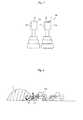
- Fig. 7 is a schematic rear elevational view showing an appearance of the work implement control device 20.
- the arm control lever 11 is in juxtaposition on the right with the bucket control lever 12 disposed on the right-hand side of the driver's seat 21.
- the kickdown switches 16, 17 described earlier are disposed at an upper surface (apex) and a left side surface (the side surface on the side of the driver's seat 21) of a grip 11a of the arm control lever 11.
- the mode changeover sub-switch 19 described earlier is disposed at a left side surface (the side surface on the side of the driver's seat 21) of a grip 12a of the bucket control lever 12.
- the sub-switch 19 may be disposed at an upper surface of the grip 12a of the bucket control lever 12 instead of, or in addition to, the left side surface of the grip 12a of the bucket control lever 12 (specifically, the sub-switch 19 may be disposed only at the upper surface (apex) of the grip 12a, or at the upper surface and the left side surface of the grip 12a as with the kickdown switches 16, 17).
- the arm control lever 11 further includes a detent mechanism 11b (schematically shown in Fig. 2 ) that maintains posture at a position at which an arm raising operation is directed.
- the kickdown switches 16, 17 and the sub-switch 19 are each a pushbutton switch and, in this embodiment, are each an alternate pushbutton.
- the controller 136 outputs a downshift signal to the transmission control unit 138 according to the operation signal and a downshift is effected one speed position each to a lower speed. If either one of the kickdown switches 16, 17 is operated at the 1st shift, the shift speed position selected with the shift speed position switch 15 is reselected.
- the depression of the sub-switch 19 during running causes the controller 136 to output a mode changeover signal to the engine control unit 137, thus changing the running mode to the P mode. If the sub-switch 19 is then depressed a second time, the running mode is returned to the E mode.
- the maximum speed of the engine 131 is limited to the low speed side, so that the maximum running driving force and the maximum vehicle speed are limited, thus improving fuel economy. Thereafter, too, each time the sub-switch 19 is operated with the main switch 18 in the E position, the running mode is repeatedly changed to the P mode, the E mode, the P mode,..
- Fig. 8 is a schematic view showing how material to be excavated, such as sand and gravel, is scooped up during loading of the material onto, for example, a dump truck using the wheel loader 100.
- the wheel loader 100 moves forward at, for example, the 2nd speed toward a mound P of the material to be excavated (hereinafter referred to simply as the "mound P") and approaches the mound P.
- the main switch 18 is placed in the E position and the E mode is selected for the running mode.
- the arm control lever 11 and the bucket control lever 12 are operated to lower the arm 121 and face an open mouth of the bucket 122 forward; immediately before penetration into the mound P, the kickdown switch 16 or 17 is depressed to kick down from the 2nd speed to the 1st speed.
- the kickdown to the 1st speed is to allow a large running driving force required for loading the material in the bucket 122 to be extracted.
- the arm raising operation is retained using the detent mechanism 11b of the arm control lever 11. This allows the arm 121 to continue performing the arm raising operation even when the operator releases the arm control lever 11.
- the bucket control lever 12 is operated to crowd the bucket 122 to thereby scoop up and capture the material to be excavated in the bucket 122.
- the amount of depression of the accelerator pedal 13 is appropriately varied to thereby adjust the running driving force (traction force). It is to be noted at this time that the running driving force may be better to be held below a predetermined level or increased to a greater level depending on the property of the material to be excavated or the road surface condition during the scooping and capturing operation.
- the operator thus needs to scoop and capture the material to be excavated in the bucket 122 by selecting the E mode or the P mode as appropriate depending on the situation to prevent the road surface from being gouged by a slipping wheel.
- the operator (D) operates the forward/reverse changeover switch 14 to select a reverse motion and reverses to be moved away from the mound P; the operator then reselects a forward motion to move to a location near a dump truck (not shown) and, operating the arm control lever 11 and the bucket control lever 12, dumps the material into, for example, a cargo deck of the dump truck.
- the selection of the E mode or the P mode as the running mode is displayed on the display 25 forward of the driver's seat 21 by a display signal output from the controller 136 based on an operation signal from the main switch 18 and the sub-switch 19.
- the embodiment can achieve the following effects.
- the depression of the sub-switch 19 allows the running mode to be changed to the P mode. This eliminates the need for releasing the work implement control device 20 and operating the main switch 18 of the side console panel 22 to thereby select the P mode during the excavating operation. This achieves good workability.
- the depression of the sub-switch 19 allows the running mode to be instantly changed to the P mode regardless of the shift speed position. This is useful when, for example, increasing the running driving force temporarily during running on an uphill road at the 2nd speed.
- a second operation on the sub-switch 19 can return the running mode back to the E mode. The operator can therefore change the running mode as desired with the main switch 18 left in the E position. Mode changing operations can thus be performed promptly and easily and the running driving force can be flexibly controlled.
- the bucket control lever 12 is disposed on the left-hand side near the operator, and the arm control lever 11 is disposed on the right-hand side farther away from the operator;
- the kickdown switches 16, 17 for forcibly effecting a downshift are disposed at the upper surface and the left side surface (specifically, the side surface closer to the driver's seat), respectively, of the grip 11a of the arm control lever 11, to thereby allow either one of the kickdown switches 16, 17 to be operated for performing the kickdown operation.
- the kickdown switch 17 disposed at the left side surface of the grip 11a can be more easily operated with the thumb of the right hand that is located on the left side of the grip 11a; if the grip 11a is gripped from a side (the right-hand side), the kickdown switch 16 disposed at the upper surface of the grip 11a can be more easily operated with the thumb of the right hand. Disposing the two kickdown switches 16, 17 on the upper surface and the left side surface, respectively, of the grip 11a of the arm control lever 11 as described above enables a downshift operation to be performed easily regardless of how the grip 11a is gripped.
- the sub-switch 19 disposed at the left side surface of the grip 12a facilitates a running mode changeover operation to be performed with the thumb of the right hand placed on the grip 12a.
- the embodiment can improve operability even further.
- a need may arise to increase the running driving force temporarily as when, for example, climbing an uphill road during running at times other than the excavating work when the work implement control device 20 is not to be operated.
- the running mode changeover operation can be performed easily even at such a time, because the mode changeover sub-switch 19 is disposed on the bucket control lever 12 that is closer to the operator. This is useful for achieving good operability.
- the embodiment has been described so that the speed detectors 145, 146 detect the torque converter speed ratio e; however, the speed ratio detecting device may have any configuration.
- the rotation of the engine 131 has been described to be transmitted to the front wheel 113 and the rear wheel 114 via the torque converter 132, the transmission 133, the propeller shaft 141, and the axles 142.
- the mechanism for transmitting the running driving force may nonetheless have any configuration.
Abstract
Description
- The present invention relates to a wheel loader that scoops up and moves excavated material.
- Work implements of wheel loaders generally include an arm cylinder that elevates an arm and a bucket cylinder that dumps or crowds a bucket. A known wheel loader includes, as control mechanisms for directing operations of the arm cylinder and the bucket cylinder, two control levers for operating the arm and the bucket, respectively. The two control levers may, for example, be disposed on the right-hand side in the cabin (hereinafter referred to as an "arm control lever" and a "bucket control lever") (see, for example, patent document 1).
- Patent Document 1
WO Publication No. 2010/147232 - A typical sequence of wheel loader operations is as follows. Specifically, the wheel loader: (A) moves to a location near a mound of soil or other material to be excavated (hereinafter referred to as the "mound" as appropriate); (B) causes an open mouth of a bucket to face forward and the bucket to penetrate into the mound with an arm lowered; (C) further advances with the bucket penetrating in the mound and, while raising the arm, crowds the bucket to thereby scoop up the material to be excavated with the bucket; and (D) with the material loaded in place in the bucket, reverses to be away from the mound, moves to a predetermined location, and dumps the material. Among the sequence of these operations, while emphasis is placed on fuel economy in the operations of (A) and (D) in which no large running driving force (traction force) is required for thrusting the material, the operations of (B) and (C) require a large running driving force for scooping up the material at appropriate timing.
- Patent document 1 discloses a wheel loader arrangement that includes a kickdown switch for quickly effecting a downshift and a mode changeover switch for temporarily canceling a restriction on the engine maximum speed and thereby increasing the maximum running driving force (changing the running mode), the kickdown switch being disposed at an upper portion of an arm control lever and the mode changeover switch being disposed at an upper portion of a bucket control lever, respectively. This arrangement enables a required large running driving force to be obtained by operating the kickdown switch to shift down to a lower shift speed when the operation is changed from (A) to (B), and an even larger running driving force to be produced by operating the mode changeover switch as appropriate according to the situation upon the operation of (C).
- In a wheel loader of this type having two control levers for operating the work implement, one for the arm and the other for the bucket, the arm control lever needs to be operated for the operation of (B) and the bucket control lever needs to be mainly operated for the operation of (C).
- The control operation to be performed during the operation of (B) is adjusting posture of the bucket and downshifting. These control operations are to be performed preliminary to the excavating, requiring no delicate adjustments as the work progresses. The control operations can be performed fairly easily with the operator resting his or her hand only lightly on the arm control lever. How the arm control lever is gripped varies depending on each individual operator. One may firmly grip the arm control lever or rest his or her hand lightly thereon, or grip the arm control lever from above or from a side.
- The control operation to be performed during the operation of (C) is to crowd the bucket and, in parallel therewith, advance the wheel loader, while raising the arm. In addition, in the operation of (C), the greater the maximum running driving force is not necessarily the better. For example, a large running driving force may be required for penetrating the bucket into the material to be excavated; meanwhile, if the wheel loader is made to run with an excessively large running driving force when running load of the excavated material is heavy, the wheels may slip to gouge the road surface, affecting subsequent work. During the operation of (C), while the bucket is crowded as the arm is raised, the maximum running driving force needs to be increased as necessary and, at the same time, the foregoing situation is properly avoided.
- As compared with the operation of (B), the operation of (C) requires a more delicate and concentrated control operation. Thus, more operators tend to grip firmly to operate the bucket control lever.
- The present invention has been made in view of the foregoing situation and in consideration of the present situation of control operations performed by an operator from a viewpoint of user friendliness and it is an object of the present invention to provide a wheel loader that can improve control operability.
-
- (1) To achieve the foregoing object, an aspect of the present invention provides a wheel loader comprising: a vehicle body having a wheel; a work implement disposed at a front portion of the vehicle body; and a work implement control device for directing an operation of the work implement, the work implement control device comprising: a control lever disposed on a side of a driver's seat, the control lever being used for directing an operation of the work implement; and two switches disposed at an upper surface and a side surface of a grip of the control lever, the side surface of the grip being on a side adjacent to the driver's seat, the two switches being used for performing operations associated with a traction force.
- (2) In the arrangement of (1) above, preferably, the work implement includes an arm, a bucket, and an arm cylinder and a bucket cylinder for driving the arm and the bucket, respectively, and the work implement control device includes: an arm control lever serving as the control lever, the arm control lever for directing an operation of the arm cylinder; a bucket control lever in juxtaposition to the arm control lever on a side adjacent to the driver's seat, the bucket control lever for directing an operation of the bucket cylinder; two kickdown switches that are the two switches disposed at the upper surface and the side surface of the grip of the arm control lever, the side surface of the grip being on the side adjacent to the driver's seat, the two kickdown switches for forcibly effecting a downshift of a shift speed position; and a mode changeover switch disposed at a side surface of a grip of the bucket control lever, the side surface of the grip being on a side adjacent to the driver's seat, the mode changeover switch being used for changing over a plurality of running modes having different engine maximum speed upper limit values from each other.
- (3) In the arrangement of (2) above, preferably, the mode changeover switch is disposed at an upper surface of the grip of the bucket control lever, in place of, or in addition to, the side surface of the grip of the bucket control lever adjacent to the driver's seat.
- (4) In the arrangement of (2) or (3) above, preferably, the mode changeover switch is a pushbutton for individually directing a changeover of a plurality of running modes having different engine maximum speed upper limit values from each other.
- (5) In the arrangement of any of (2) to (4) above, preferably, the wheel loader further comprises display means for displaying a running mode selected with the mode changeover switch.
- (6) In the arrangement of any of (2) to (5) above, preferably, the wheel loader further comprises a detent mechanism for maintaining posture of the arm control lever at a position at which an arm raising operation is directed.
- The present invention can achieve even better operability by flexibly disposing the kickdown switch and the mode changeover switch according to different modes of operation of the operator.
-
-
Fig. 1 is a side elevational view showing a wheel loader according to an embodiment of the present invention. -
Fig. 2 is a block diagram showing a schematic configuration of a drive system disposed in the wheel loader according to the embodiment of the present invention. -
Fig. 3 is a running performance diagram (torque diagram) showing a relation between an engine speed and torque when an accelerator pedal is fully depressed in the wheel loader according to the embodiment of the present invention. -
Fig. 4 is a graph showing a relation between a vehicle speed and a running driving force at each of different shift speeds in the wheel loader according to the embodiment of the present invention. -
Fig. 5 is a plan view showing a configuration of a cabin in the wheel loader according to the embodiment of the present invention. -
Fig. 6 is a schematic view showing a main switch for changing a running mode in the wheel loader according to the embodiment of the present invention. -
Fig. 7 is a schematic rear elevational view showing an appearance of work implement control devices in the wheel loader according to the embodiment of the present invention. -
Fig. 8 is a schematic view showing how material to be excavated, such as sand and gravel, is scooped up during loading of the material onto, for example, a dump truck using the wheel loader according to the embodiment of the present invention. - An embodiment of the present invention will be described below with reference to the accompanying drawings.
-
Fig. 1 is a side elevational view showing a wheel loader according to an embodiment of the present invention. - A
wheel loader 100 shown inFig. 1 includes avehicle body 110 and a work implement 120 mounted at a front portion of the vehicle body 101. - The
vehicle body 110 includes afront vehicle body 111 and arear vehicle body 112. Thefront vehicle body 111 and therear vehicle body 112 include a front wheel (tire) 113 and a rear wheel (tire) 114, respectively. Thefront vehicle body 111 and therear vehicle body 112 are mutually bendably connected to each other via acenter pin 115 extending in a vertical direction. Thefront vehicle body 111 and therear vehicle body 112 are connected to a steering cylinder, not shown. With a telescopic drive of the steering cylinder, thefront vehicle body 111 bends to the right or left relative to therear vehicle body 112. Acabin 116 is mounted at a front portion on therear vehicle body 112 and anengine compartment 117 is mounted at a rear portion on therear vehicle body 112. Theengine compartment 117 houses therein, for example, anengine 131 as a prime mover to be described later, ahydraulic pump 134 driven by theengine 131, and acontrol valve 135 that controls a direction and a flow rate of hydraulic fluid delivered from thehydraulic pump 134. - The
work implement 120 includes anarm 121 and abucket 122. The work implement 120 further includes anarm cylinder 123 and abucket cylinder 124 for driving thearm 121 and thebucket 122, respectively. With a telescopic drive of thearm cylinder 123, thearm 121 is rotated vertically (elevating). With a telescopic drive of thebucket cylinder 124, thebucket 122 is rotated vertically (dumping or crowding). -
Fig. 2 is a block diagram showing a schematic configuration of a drive system of thewheel loader 100. - As shown in
Fig. 2 , thedrive system 130 of thewheel loader 100 includes theengine 131, atorque converter 132, atransmission 133, thehydraulic pump 134, thecontrol valve 135, acontroller 136, anengine control unit 137, and atransmission control unit 138. - The
engine 131 has an output shaft connected to an input shaft of thetorque converter 132. Thetorque converter 132 has an output shaft connected to thetransmission 133. Thetorque converter 132 is a well-known fluid coupling including an impeller, a turbine, and a stator. Rotation of theengine 131 is transmitted to thetransmission 133 via thetorque converter 132. Thetransmission 133 includes a hydraulic clutch that changes shift speed positions of thetransmission 133. Thetransmission 133 changes speeds of rotation of the output shaft of thetorque converter 132. Rotation after the speed change is transmitted to thefront wheel 113 and therear wheel 114 via apropeller shaft 141 andaxles 142. This causes thewheel loader 100 to run. - The
hydraulic pump 134 is a variable displacement type driven by theengine 131 to deliver hydraulic fluid. The hydraulic fluid delivered from thehydraulic pump 134, while having its direction and flow rate controlled by thecontrol valve 135, is supplied to work actuators, such as thearm cylinder 123 and thebucket cylinder 124, thereby driving the work actuators. Thecontrol valve 135 is operated by anarm control lever 11 and a bucket control lever 12 (to be described later). Thecontrol valve 135 controls flow of the hydraulic fluid to thearm cylinder 123 or thebucket cylinder 124 according to an operation signal from thearm control lever 11 or thebucket control lever 12. Thehydraulic pump 134 has a pump capacity varied by a regulator (not shown). The regulator varies the pump capacity according to the pump delivery pressure to thereby perform, for example, constant torque control in which work torque remains constant. It is noted that a fixed displacement pump, such as a gear pump, may be used for thehydraulic pump 134. - The
controller 136 is configured to include an arithmetic processing unit that includes a CPU, a ROM, a RAM, and other peripheral circuits. Thecontroller 136 receives inputs of signals from an acceleratoroperation amount detector 143, avehicle speed detector 144, aspeed detector 145, aspeed detector 146, a forward/reverse changeover switch 14, a shiftspeed position switch 15, kickdown switches 16, 17, a main mode changeover switch 18 (hereinafter referred to as a "main switch 18"), and a sub-mode changeover switch 19 (hereinafter referred to as a "sub-switch 19"). Specifically, the acceleratoroperation amount detector 143 detects an operation amount of anaccelerator pedal 13. Thevehicle speed detector 144 detects a rotational speed of the output shaft of the transmission 133 (or the propeller shaft 141) as a vehicle speed. Thespeed detector 145 detects a rotational speed Ni of the input shaft of thetorque converter 132. Thespeed detector 146 detects a rotational speed Nt of the output shaft of thetorque converter 132. The forward/reverse changeover switch 14 selects a forward mode (F), a reverse mode (R), or a neutral mode (N) of thewheel loader 100. The shiftspeed position switch 15 specifies an upper limit of a shift speed position among 1st to 4th speeds. The kickdown switches 16, 17 direct a changeover of the shift speed to a lower speed. Themain switch 18 selects a running mode of either a power mode (hereinafter referred to as a "P mode") in which emphasis is placed on workability or an economy mode (hereinafter referred to as an "E mode") in which emphasis is placed on fuel economy. The sub-switch 19 also selects the running mode of either the P mode or the E mode. - In the embodiment, each of the kickdown switches 16, 17 and the sub-switch 19 is a pushbutton switch having therein predetermined play. To prevent an operation signal from being output when a finger or a palm of an operator covers and slightly depresses the switch (to avoid an operation unintended by the operator), the switch is designed to have a certain allowance so as not to output the operation signal unless the switch is depressed a required stroke.
- The
torque converter 132 has a function of increasing output torque relative to input torque, specifically, having a torque ratio of 1 or more. The torque ratio decreases with an increase in a torque converter speed ratio e (output rotational speed Nt/input rotational speed Ni), specifically, a ratio of the rotational speed of the input shaft to that of the output shaft of thetorque converter 132. When, for example, running load increases during running at a constant engine speed, the output rotational speed Nt of thetorque converter 132, specifically, the vehicle speed decreases with a resultant small torque converter speed ratio e. Since the torque ratio increases at this time, the vehicle can run with an even greater running driving force (traction force). Specifically, a low vehicle speed results in an increasing running driving force (low speed high torque) and a high vehicle speed results in a decreasing running driving force (high speed low torque). - The
transmission 133 is an automatic transmission having a clutch and a solenoid valve associated with each shift speed position of the 1st to 4th speeds. Each of the solenoid valves is driven by a control signal output from thecontroller 136 to thetransmission control unit 138, causing hydraulic fluid to act on a corresponding clutch to thereby change a clutch position. Thecontroller 136 stores in advance therein a torque converter speed ratio e1 that serves as a reference for upshifting and a torque converter speed ratio e2 that serves as a reference for downshifting. In an automatic transmission mode, thecontroller 136 calculates the torque converter speed ratio e using signals from thespeed detectors controller 136 outputs an upshift signal to thetransmission control unit 138. If the calculated torque converter speed ratio e is smaller than the torque converter speed ratio e2, thecontroller 136 outputs a downshift signal to thetransmission control unit 138. This allows the shift speed position of thetransmission 133 to be automatically changed among the 1st to 4th speeds according to the torque converter speed ratio e. - At this time, the shift speed position is automatically changed with the shift speed position selected with the shift
speed position switch 15 as the upper limit. For example, if the 2nd speed is selected with the shiftspeed position switch 15, the shift speed position is either the 1st speed or the 2nd speed according to the torque converter speed ratio e. If the 1st speed is selected with the shiftspeed position switch 15, the shift speed position is fixed at the 1st speed. Though not shown, the arrangement may include a function that changes from the automatic transmission mode to a manual transmission mode and, in the manual transmission mode, the shiftspeed position switch 15 or another separately provided switch may be manually operated to select any shift speed position. - The kickdown switches 16, 17 forcibly effect a downshift to a lower shift speed position. Each time the
kickdown switch 16 or thekickdown switch 17 is operated once, thecontroller 136 outputs a downshift signal to thetransmission control unit 138 to forcibly effect a downshift by one speed at a time regardless of the torque converter speed ratio e. In the automatic transmission mode, operating thekickdown switch 16 or thekickdown switch 17 when, for example, the vehicle speed is low allows a downshift to be effected forcibly. - In the arrangement described above, an upshift or a downshift is effected when the torque converter speed ratio e is greater or smaller than the predetermined value e1 or e2. Alternatively, a gearshift may even be effected when the vehicle speed reaches a predetermined value. Such an arrangement can be achieved by, for example, causing an upshift signal or a downshift signal to be output to the
transmission control unit 138 according to a signal from thevehicle speed detector 144. - The
controller 136 also brings the engine speed to a target engine speed according to the operation amount of theaccelerator pedal 13. Specifically, a greater depression amount of theaccelerator pedal 13 results in an increased target engine speed and thecontroller 136 outputs a control signal corresponding to the target engine speed, thereby controlling the engine speed. -
Fig. 3 is a running performance diagram (torque diagram) showing a relation between the engine speed and torque when theaccelerator pedal 13 is fully depressed. - In
Fig. 3 , characteristics Ap and Ae are torque diagrams when the running mode is the P mode and the E mode, respectively. Whereas the engine maximum speed is not limited in the P mode, the engine maximum speed is limited in the E mode to a point on the low speed side. - Characteristics B0 to B2 are exemplary input torque values when the
transmission 133 is driven by theengine 131, indicating that the input torque increases with an increasing engine speed. This input torque includes input torque of thehydraulic pump 134 and varies as shown by the characteristics B0 to B2 according to the torque converter speed ratio e and suction torque of thehydraulic pump 134. Specifically, a smaller torque converter speed ratio e results in greater input torque (the characteristic B0) and a greater torque converter speed ratio e results in smaller input torque (the characteristic B2). - An intersection between the characteristic Ap/Ae and the characteristic B0/B1/B2 is a matching point and the engine speed is the value of the matching point. Thus, the engine speed relative to predetermined input torque is higher in the P mode than in the E mode. With the engine speed at the matching point, the running driving force is proportional to the square of the engine speed N. Thus, the running driving force is greater in the P mode than in the E mode and a maximum vehicle speed at each shift speed is faster by a margin of the higher engine speed.
-
Fig. 4 is a graph showing a relation between the vehicle speed and the running driving force at each of different shift speeds. InFig. 4 , solid lines represent characteristics in the P mode and dotted lines represent characteristics in the E mode. - A comparison made at the same shift speed in
Fig. 4 reveals that the running driving force is greater at a lower vehicle speed (low speed high torque) and smaller at a higher vehicle speed (high speed low torque). Additionally, the lower the shift speed position, the greater the running driving force obtained at the same vehicle speed. Specifically, the maximum running driving force is greater and the maximum vehicle speed is higher in the P mode than in the E mode. At the 2nd speed position, for example, a maximum running driving force F2 in the P mode is greater than a maximum running driving force F2' in the E mode and a maximum vehicle speed V2hi in the P mode is higher than a maximum vehicle speed V2'hi in the E mode. -
Fig. 5 is a plan view showing a configuration of thecabin 116. - A
side console panel 22 and a work implementcontrol device 20 are disposed on the right of a driver'sseat 21. Afront panel 23 forward of the driver'sseat 21 includes asteering wheel 27, the forward/reverse changeover switch 14, and amonitor panel 24. Themonitor panel 24 includes adisplay 25 that indicates whether the E mode or the P mode is selected. The forward/reverse changeover switch 14 has the shiftspeed position switch 15 disposed at a leading end thereof. In addition, theaccelerator pedal 13 and right and leftbrake pedals 26 are disposed forwardly of the driver'sseat 21 and downwardly of thefront panel 23. - The abovementioned mode changeover main switch 18 (see
Fig. 6 also) is disposed on theside console panel 22. Themain switch 18 is an alternate switch that is placed in either a P position indicating the P mode or an E position indicating the E mode. The work implementcontrol device 20 is disposed forwardly of theside console panel 22. The work implementcontrol device 20 includes thebucket control lever 12 that directs an operation of thebucket cylinder 124, thearm control lever 11 that directs an operation of thearm cylinder 123, the sub-switch 19 that selects either the E mode or the P mode, the two modes having an engine maximum speed upper limit value different from each other, and the twokickdown switches -
Fig. 7 is a schematic rear elevational view showing an appearance of the work implementcontrol device 20. - As shown in
Fig. 7 , thearm control lever 11 is in juxtaposition on the right with thebucket control lever 12 disposed on the right-hand side of the driver'sseat 21. The kickdown switches 16, 17 described earlier are disposed at an upper surface (apex) and a left side surface (the side surface on the side of the driver's seat 21) of a grip 11a of thearm control lever 11. Themode changeover sub-switch 19 described earlier is disposed at a left side surface (the side surface on the side of the driver's seat 21) of agrip 12a of thebucket control lever 12. The sub-switch 19 may be disposed at an upper surface of thegrip 12a of thebucket control lever 12 instead of, or in addition to, the left side surface of thegrip 12a of the bucket control lever 12 (specifically, the sub-switch 19 may be disposed only at the upper surface (apex) of thegrip 12a, or at the upper surface and the left side surface of thegrip 12a as with the kickdown switches 16, 17). Thearm control lever 11 further includes adetent mechanism 11b (schematically shown inFig. 2 ) that maintains posture at a position at which an arm raising operation is directed. - As described earlier, the kickdown switches 16, 17 and the sub-switch 19 are each a pushbutton switch and, in this embodiment, are each an alternate pushbutton. Thus, each time either one of the kickdown switches 16, 17 is operated once during running at a shift speed position other than the 1st speed (if there exists any other lower shift speed position), the
controller 136 outputs a downshift signal to thetransmission control unit 138 according to the operation signal and a downshift is effected one speed position each to a lower speed. If either one of the kickdown switches 16, 17 is operated at the 1st shift, the shift speed position selected with the shiftspeed position switch 15 is reselected. If, however, the 1st speed is selected with the shiftspeed position switch 15, no gearshift is effected from the 1st speed regardless whether the kickdown switches 16, 17 are operated. The operation on the sub-switch 19 is accepted by thecontroller 136, only if the E mode has been selected with themain switch 18. Specifically, when the P mode has been selected with themain switch 18, the running mode is fixed in the P mode and operating the sub-switch 19 does not cause thecontroller 136 to output a running mode changeover signal to theengine control unit 137, so that the running mode is not to be changed to the E mode. At this time, the maximum speed of theengine 131 is not limited and the running driving force and the vehicle speed can be maximized within the capacity of theengine 131. If the E mode has been selected with themain switch 18, on the other hand, the depression of the sub-switch 19 during running causes thecontroller 136 to output a mode changeover signal to theengine control unit 137, thus changing the running mode to the P mode. If the sub-switch 19 is then depressed a second time, the running mode is returned to the E mode. In the E mode, the maximum speed of theengine 131 is limited to the low speed side, so that the maximum running driving force and the maximum vehicle speed are limited, thus improving fuel economy. Thereafter, too, each time the sub-switch 19 is operated with themain switch 18 in the E position, the running mode is repeatedly changed to the P mode, the E mode, the P mode,.. - A typical sequence of excavating operations performed by the wheel loader having the arrangements as described heretofore will be described below.
-
Fig. 8 is a schematic view showing how material to be excavated, such as sand and gravel, is scooped up during loading of the material onto, for example, a dump truck using thewheel loader 100. - As shown in
Fig. 8 , when the material to be excavated is to be scooped up, typically, (A) thewheel loader 100 moves forward at, for example, the 2nd speed toward a mound P of the material to be excavated (hereinafter referred to simply as the "mound P") and approaches the mound P. At this time, themain switch 18 is placed in the E position and the E mode is selected for the running mode. Then, (B) thearm control lever 11 and thebucket control lever 12 are operated to lower thearm 121 and face an open mouth of thebucket 122 forward; immediately before penetration into the mound P, thekickdown switch bucket 122 to be extracted. - Upon penetration into the mound P, (C) the arm raising operation is retained using the
detent mechanism 11b of thearm control lever 11. This allows thearm 121 to continue performing the arm raising operation even when the operator releases thearm control lever 11. During the arm raising operation, thebucket control lever 12 is operated to crowd thebucket 122 to thereby scoop up and capture the material to be excavated in thebucket 122. When the material is to be scooped up and captured, the amount of depression of theaccelerator pedal 13 is appropriately varied to thereby adjust the running driving force (traction force). It is to be noted at this time that the running driving force may be better to be held below a predetermined level or increased to a greater level depending on the property of the material to be excavated or the road surface condition during the scooping and capturing operation. The operator thus needs to scoop and capture the material to be excavated in thebucket 122 by selecting the E mode or the P mode as appropriate depending on the situation to prevent the road surface from being gouged by a slipping wheel. When the material has been captured in thebucket 122, the operator (D) operates the forward/reverse changeover switch 14 to select a reverse motion and reverses to be moved away from the mound P; the operator then reselects a forward motion to move to a location near a dump truck (not shown) and, operating thearm control lever 11 and thebucket control lever 12, dumps the material into, for example, a cargo deck of the dump truck. - It is noted that the selection of the E mode or the P mode as the running mode is displayed on the
display 25 forward of the driver'sseat 21 by a display signal output from thecontroller 136 based on an operation signal from themain switch 18 and the sub-switch 19. - The embodiment can achieve the following effects.
- As described above, when a large running driving force is temporarily required, the depression of the sub-switch 19 allows the running mode to be changed to the P mode. This eliminates the need for releasing the work implement
control device 20 and operating themain switch 18 of theside console panel 22 to thereby select the P mode during the excavating operation. This achieves good workability. In addition, the depression of the sub-switch 19 allows the running mode to be instantly changed to the P mode regardless of the shift speed position. This is useful when, for example, increasing the running driving force temporarily during running on an uphill road at the 2nd speed. Even after the running mode has been changed to the P mode through the operation on the sub-switch 19, a second operation on the sub-switch 19 can return the running mode back to the E mode. The operator can therefore change the running mode as desired with themain switch 18 left in the E position. Mode changing operations can thus be performed promptly and easily and the running driving force can be flexibly controlled. - It is here noted that, in general, different operators hold onto the grip 11a of the
arm control lever 11 in different manners: some may firmly grip or hold only lightly onto the grip 11a, others may grip the grip 11a from above or from a side. How the grip 11a is held varies depending on situations and preference of each individual operator. In the embodiment, therefore, thebucket control lever 12 is disposed on the left-hand side near the operator, and thearm control lever 11 is disposed on the right-hand side farther away from the operator; the kickdown switches 16, 17 for forcibly effecting a downshift are disposed at the upper surface and the left side surface (specifically, the side surface closer to the driver's seat), respectively, of the grip 11a of thearm control lever 11, to thereby allow either one of the kickdown switches 16, 17 to be operated for performing the kickdown operation. As a result, if the grip 11a is gripped from the above, thekickdown switch 17 disposed at the left side surface of the grip 11a can be more easily operated with the thumb of the right hand that is located on the left side of the grip 11a; if the grip 11a is gripped from a side (the right-hand side), thekickdown switch 16 disposed at the upper surface of the grip 11a can be more easily operated with the thumb of the right hand. Disposing the twokickdown switches arm control lever 11 as described above enables a downshift operation to be performed easily regardless of how the grip 11a is gripped. - When the material to be excavated is to be scooped up by the
bucket 122, operations of crowding the bucket, raising the arm, and moving the wheel loader forward need to be performed in parallel with each other. When thedetent mechanism 11b of thearm control lever 11 is to be used for the arm raising operation, the operator tends to let go of thearm control lever 11 and grip thegrip 12a from above to thereby operate thebucket control lever 12. A large running driving force can be required as appropriate depending on the situation during the operation of thebucket control lever 12. Even in such a case, thebucket control lever 12 that is being operated has themode changeover sub-switch 19, so that the sub-switch 19 can be operated even with thebucket control lever 12 held in hand. This eliminates the need for releasing the work implementcontrol device 20 or holding a different control lever in order to change the running mode. Moreover, the sub-switch 19 disposed at the left side surface of thegrip 12a facilitates a running mode changeover operation to be performed with the thumb of the right hand placed on thegrip 12a. - Locations and the number of kickdown switches 16, 17 and the running
mode changeover sub-switch 19 are optimized by disposing these switches appropriately on thearm control lever 11 and thebucket control lever 12 in consideration of actual excavating work of the material to be excavated as described above. Operability can thereby be improved even further. In addition, disposing the kickdown switches 16, 17 and the runningmode changeover sub-switch 19 appropriately on thearm control lever 11 and thebucket control lever 12, respectively, reduces the likelihood of confusing the kickdown operation with the running mode changeover operation, thereby containing erroneous operations. - As described above, the embodiment can improve operability even further.
- In addition, a need may arise to increase the running driving force temporarily as when, for example, climbing an uphill road during running at times other than the excavating work when the work implement
control device 20 is not to be operated. The running mode changeover operation can be performed easily even at such a time, because themode changeover sub-switch 19 is disposed on thebucket control lever 12 that is closer to the operator. This is useful for achieving good operability. - The kickdown switches 16, 17 and the
mode changeover sub-switch 19 are each an alternate switch. Any shift speed position or any running mode can therefore be selected individually for each of theswitches switches grips 11a, 12a of thearm control lever 11 and thebucket control lever 12. Being able to dispose theswitches grips 11a, 12a in the above-described manner greatly contributes to achieving the abovementioned high operability. Each of theswitches - The selected running mode is displayed on the
display 25 of themonitor panel 24 as required. The operator is thus able to determine the running mode on thedisplay 25 as necessary even if the running mode is frequently changed with the sub-switch 19. This allows the operator to perform operations while determining the running mode as necessary, so that he or she can easily set the running mode according to his or her intention. An erroneous operation can thus be prevented. Specifically, for example, when the operator mistakenly perceives that the E mode is selected when the P mode is actually selected and depresses theaccelerator 13, resulting in the increasing running driving force against the intention of the operator and gouging the road surface. - The above embodiment has been exemplarily described with respect to an arrangement in which the running
mode changeover sub-switch 19 is disposed only at the left side surface of thegrip 12a of thebucket control lever 12. This is, however, not the only possible arrangement; alternatively, the sub-switch 19 may be disposed only at the upper surface of thegrip 12a or at each of the upper surface and the left side surface (two sub-switches 19 in total). Assuming that thegrip 12a of thebucket control lever 12 is gripped from a side, themode changeover sub-switch 19 disposed on the upper portion of thegrip 12a of thebucket control lever 12 can be easily depressed with the thumb of the right hand. If different operators grip thebucket control lever 12 differently, it is useful to have the sub-switches 19 on the upper surface and the left side surface of thegrip 12a of thebucket control lever 12. - Although the sub-switch 19 of an alternate type has been exemplarily described, a momentary switch of the same pushbutton type may be used because of an intended use of the sub-switch 19 for a temporary and short-period changeover of the running mode. If a momentary switch is used for the sub-switch 19 and when the sub-switch 19 is depressed with the E mode selected with the
main switch 18, thecontroller 136 outputs a mode changeover signal to theengine control unit 137 according to the operation signal. The running mode is changed to the P mode as long as the sub-switch 19 is held down and, when the depression of the sub-switch 19 is stopped, the running mode is returned to the E mode. - The embodiment has been described such that the output of a control signal from the
controller 136 to theengine control unit 137 does not cause the maximum speed of theengine 131 to be limited when the P mode is selected, but causes the maximum speed of theengine 131 to be limited in the E mode to a point on the low speed side. However, the engine maximum speed in the P mode needs only to be shifted to a higher speed side than the engine maximum speed in the E mode and the engine maximum speed in the P mode is not necessarily to be unlimited. The embodiment has also been described to include the E mode and the P mode for the running mode. The running mode may still include three or more modes having different engine maximum speed upper limit values. In this case, preferably, each press of the sub-switch 19 changes the running mode in sequence in the same manner as with the shift speed position being changed one speed position each time thekickdown switch - The embodiment has been described so that the
speed detectors engine 131 has been described to be transmitted to thefront wheel 113 and therear wheel 114 via thetorque converter 132, thetransmission 133, thepropeller shaft 141, and theaxles 142. The mechanism for transmitting the running driving force may nonetheless have any configuration. - Not only the kickdown switches 16, 17, but also the sub-switch 19 as the mode changeover switch can be disposed at two places on the upper surface and the side surface adjacent to the driver's
seat 21 of the grips of the control levers, as described earlier. The downshift operation using the kickdown switches 16, 17 and the gearshift operation using the sub-switch 19 are commonly related to each other as an operation associated with the traction force. An arrangement in which twosub-switches 19 are disposed at two places of the grip can contribute to improved operability during scooping of sand or the like depending on operator conditions. - Additionally, the embodiment has been described for an exemplary case in which the
arm control lever 11 and thebucket control lever 12 are disposed on the right of the driver'sseat 21. Nonetheless, thearm control lever 11 and thebucket control lever 12 may still be disposed on the left of the driver'sseat 21. Furthermore, preferably, thebucket control lever 12 is disposed on the side of thearm control lever 11 adjacent to the driver'sseat 21. An arrangement is nonetheless possible in which thearm control lever 12 is disposed on the side adjacent to the driver'sseat 21. - At this time, of the kickdown switches 16, 17 and the sub-switch 19, those to be disposed at the side surface of the grip 11a of the
arm control lever 11 and the side surface of thegrip 12a of thebucket control lever 12 are to be disposed at the side surfaces of thegrips 11a, 12a adjacent to the driver'sseat 21, because those switches are intended to be operated with the thumb when the grips are gripped from the above as described earlier. If thearm control lever 11 and thebucket control lever 12 are disposed on the left of the driver'sseat 21, therefore, the kickdown switches 16, 17 are to be disposed at the upper surface and the right side surface of the grip 11a of thearm control lever 11. Similarly, if the sub-switch 19 is to be disposed at a side surface of thegrip 12a of thebucket control lever 12 disposed on the left of the driver'sseat 21, the sub-switch 19 is disposed at the side surface of thegrip 12a adjacent to the driver'sseat 21, specifically, the right side surface of thegrip 12a. -
- 11
- Arm control lever
- 11a
- Grip
- 11b
- Detent mechanism
- 12
- Bucket control lever
- 12a
- Grip
- 16, 17
- Kickdown switch
- 19
- Sub-switch (mode changeover switch)
- 20
- Work implement control device
- 21
- Driver's
seat 21 - 25
- Display (display means)
- 100
- Wheel loader
- 110
- Vehicle body
- 113
- Front wheel
- 114
- Rear wheel
- 120
- Work implement
- 121
- Arm
- 122
- Bucket
- 123
- Arm cylinder
- 124
- Bucket cylinder
Claims (6)
- A wheel loader comprising:a vehicle body having a wheel;a work implement disposed at a front portion of the vehicle body; anda work implement control device for directing an operation of the work implement, the work implement control device comprising:a control lever disposed on a side of a driver's seat, the control lever being used for directing an operation of the work implement; andtwo switches disposed at an upper surface and a side surface of a grip of the control lever, the side surface of the grip being on a side adjacent to the driver's seat, the two switches being used for performing operations associated with a traction force.
- The wheel loader according to claim 1, wherein
the work implement includes an arm, a bucket, and an arm cylinder and a bucket cylinder for driving the arm and the bucket, respectively, and
the work implement control device includes:an arm control lever serving as the control lever, the arm control lever being used for directing an operation of the arm cylinder;a bucket control lever in juxtaposition to the arm control lever on a side adjacent to the driver's seat, the bucket control lever being used for directing an operation of the bucket cylinder;two kickdown switches that are the two switches disposed at the upper surface and the side surface of the grip of the arm control lever, the side surface of the grip being on the side adjacent to the driver's seat, the two kickdown switches being used for forcibly effecting a downshift of a shift speed position; anda mode changeover switch disposed at a side surface of a grip of the bucket control lever, the side surface of the grip being on a side adjacent to the driver's seat, the mode changeover switch being used for changing over a plurality of running modes having different engine maximum speed upper limit values from each other. - The wheel loader according to claim 2, wherein the mode changeover switch is disposed at an upper surface of the grip of the bucket control lever, in place of, or in addition to, the side surface of the grip of the bucket control lever adjacent to the driver's seat.
- The wheel loader according to claim 2 or 3, wherein
the mode changeover switch is a pushbutton for individually directing a changeover of a plurality of running modes having different engine maximum speed upper limit values from each other. - The wheel loader according to any one of claims 2 to 4, further comprising:display means for displaying a running mode selected with the mode changeover switch.
- The wheel loader according to any one of claims 2 to 5, further comprising:a detent mechanism for maintaining posture of the arm control lever at a position at which an arm raising operation is directed.
Applications Claiming Priority (2)
| Application Number | Priority Date | Filing Date | Title |
|---|---|---|---|
| JP2011057076 | 2011-03-15 | ||
| PCT/JP2012/056714 WO2012124767A1 (en) | 2011-03-15 | 2012-03-15 | Wheel rotor |
Publications (3)
| Publication Number | Publication Date |
|---|---|
| EP2687638A1 true EP2687638A1 (en) | 2014-01-22 |
| EP2687638A4 EP2687638A4 (en) | 2014-12-17 |
| EP2687638B1 EP2687638B1 (en) | 2017-05-10 |
Family
ID=46830832
Family Applications (1)
| Application Number | Title | Priority Date | Filing Date |
|---|---|---|---|
| EP12758204.7A Active EP2687638B1 (en) | 2011-03-15 | 2012-03-15 | Wheel loader |
Country Status (6)
| Country | Link |
|---|---|
| US (1) | US20140003900A1 (en) |
| EP (1) | EP2687638B1 (en) |
| JP (1) | JP5814258B2 (en) |
| KR (1) | KR101882406B1 (en) |
| CN (1) | CN103370479B (en) |
| WO (1) | WO2012124767A1 (en) |
Cited By (1)
| Publication number | Priority date | Publication date | Assignee | Title |
|---|---|---|---|---|
| EP2891783A4 (en) * | 2014-10-31 | 2015-11-04 | Komatsu Mfg Co Ltd | Wheel loader and wheel loader control method |
Families Citing this family (12)
| Publication number | Priority date | Publication date | Assignee | Title |
|---|---|---|---|---|
| JP6034773B2 (en) * | 2013-11-13 | 2016-11-30 | 株式会社クボタ | Working machine |
| CN103671888A (en) * | 2013-12-18 | 2014-03-26 | 徐州凯尔农业装备股份有限公司 | Electric control gear shifting device of roller tractor |
| JP6587279B2 (en) * | 2015-07-03 | 2019-10-09 | キャタピラー エス エー アール エル | Travel control system for construction machinery |
| US10041229B2 (en) * | 2015-11-02 | 2018-08-07 | Caterpillar Inc. | System and method for controlling operation of machine |
| JP6487822B2 (en) * | 2015-11-05 | 2019-03-20 | ヤンマー株式会社 | Tractor |
| CN108301457B (en) * | 2018-03-14 | 2021-02-19 | 华侨大学 | Excavator start and stop control method |
| JP6806726B2 (en) * | 2018-03-27 | 2021-01-06 | 日立建機株式会社 | Work vehicle |
| WO2020003948A1 (en) * | 2018-06-29 | 2020-01-02 | 株式会社クボタ | Work machine |
| CN109515537B (en) * | 2018-11-16 | 2020-06-09 | 中联重科股份有限公司 | Control method and system for crawler vehicle travelling mechanism and crawler vehicle |
| EP4015277A1 (en) * | 2020-12-15 | 2022-06-22 | Kubota Corporation | Work vehicle, control method, control program and recording medium |
| CN112982538B (en) * | 2021-02-24 | 2022-06-21 | 索特传动设备有限公司 | Control method and device of wheel loader, wheel loader and storage medium |
| JP2023082323A (en) * | 2021-12-02 | 2023-06-14 | 株式会社小松製作所 | Cab and work machine |
Citations (6)
| Publication number | Priority date | Publication date | Assignee | Title |
|---|---|---|---|---|
| US20050279561A1 (en) * | 2004-06-22 | 2005-12-22 | Caterpillar Inc. | Work machine joystick control system |
| WO2009048364A1 (en) * | 2007-10-08 | 2009-04-16 | Svab Hydraulik Ab | A control lever for operating a machine, a procedure for operating a machine via a control lever and the use of the control lever |
| US20090240406A1 (en) * | 2005-12-22 | 2009-09-24 | Komatsu Ltd. | Engine control device for working vehicle |
| US7784581B1 (en) * | 2006-09-14 | 2010-08-31 | Deere & Company | Machine control interlocks for an electrohydraulically controlled vehicle |
| WO2010147232A1 (en) * | 2009-06-19 | 2010-12-23 | 日立建機株式会社 | Motor control device for working vehicle |
| EP2277369A1 (en) * | 2009-07-20 | 2011-01-26 | CLAAS Selbstfahrende Erntemaschinen GmbH | Multifunction handle |
Family Cites Families (8)
| Publication number | Priority date | Publication date | Assignee | Title |
|---|---|---|---|---|
| JP2000105618A (en) * | 1998-07-28 | 2000-04-11 | Komatsu Ltd | Lever type signal generator |
| US6098481A (en) * | 1998-12-15 | 2000-08-08 | Caterpillar Inc. | High force variable position detent mechanism |
| US6643577B1 (en) * | 2002-08-22 | 2003-11-04 | Caterpillar Inc | Operator control station and method for a work machine having more than one function |
| FR2858861B1 (en) * | 2003-08-11 | 2007-06-22 | Manitou Bf | INTERACTION CONTROL DEVICE WITH THE HAND OF AN OPERATOR |
| KR100621982B1 (en) * | 2004-04-13 | 2006-09-14 | 볼보 컨스트럭션 이키프먼트 홀딩 스웨덴 에이비 | Apparatus for setting function of switches of working vehicle |
| US9074352B2 (en) * | 2006-03-27 | 2015-07-07 | John R. Ramun | Universal control scheme for mobile hydraulic equipment and method for achieving the same |
| US8230757B2 (en) * | 2008-07-29 | 2012-07-31 | Deere & Company | Lever lockout assembly |
| JP5238448B2 (en) * | 2008-10-20 | 2013-07-17 | キャタピラー エス エー アール エル | Work vehicle |
-
2012
- 2012-03-15 WO PCT/JP2012/056714 patent/WO2012124767A1/en active Application Filing
- 2012-03-15 US US13/996,247 patent/US20140003900A1/en not_active Abandoned
- 2012-03-15 EP EP12758204.7A patent/EP2687638B1/en active Active
- 2012-03-15 KR KR1020137020848A patent/KR101882406B1/en active IP Right Grant
- 2012-03-15 CN CN201280008246.2A patent/CN103370479B/en active Active
- 2012-03-15 JP JP2012547350A patent/JP5814258B2/en active Active
Patent Citations (6)
| Publication number | Priority date | Publication date | Assignee | Title |
|---|---|---|---|---|
| US20050279561A1 (en) * | 2004-06-22 | 2005-12-22 | Caterpillar Inc. | Work machine joystick control system |
| US20090240406A1 (en) * | 2005-12-22 | 2009-09-24 | Komatsu Ltd. | Engine control device for working vehicle |
| US7784581B1 (en) * | 2006-09-14 | 2010-08-31 | Deere & Company | Machine control interlocks for an electrohydraulically controlled vehicle |
| WO2009048364A1 (en) * | 2007-10-08 | 2009-04-16 | Svab Hydraulik Ab | A control lever for operating a machine, a procedure for operating a machine via a control lever and the use of the control lever |
| WO2010147232A1 (en) * | 2009-06-19 | 2010-12-23 | 日立建機株式会社 | Motor control device for working vehicle |
| EP2277369A1 (en) * | 2009-07-20 | 2011-01-26 | CLAAS Selbstfahrende Erntemaschinen GmbH | Multifunction handle |
Non-Patent Citations (1)
| Title |
|---|
| See also references of WO2012124767A1 * |
Cited By (2)
| Publication number | Priority date | Publication date | Assignee | Title |
|---|---|---|---|---|
| EP2891783A4 (en) * | 2014-10-31 | 2015-11-04 | Komatsu Mfg Co Ltd | Wheel loader and wheel loader control method |
| US9458603B2 (en) | 2014-10-31 | 2016-10-04 | Komatsu Ltd. | Wheel loader and control method for wheel loader |
Also Published As
| Publication number | Publication date |
|---|---|
| JP5814258B2 (en) | 2015-11-17 |
| CN103370479A (en) | 2013-10-23 |
| EP2687638B1 (en) | 2017-05-10 |
| KR101882406B1 (en) | 2018-07-26 |
| JPWO2012124767A1 (en) | 2014-07-24 |
| KR20140051120A (en) | 2014-04-30 |
| US20140003900A1 (en) | 2014-01-02 |
| CN103370479B (en) | 2016-06-01 |
| WO2012124767A1 (en) | 2012-09-20 |
| EP2687638A4 (en) | 2014-12-17 |
Similar Documents
| Publication | Publication Date | Title |
|---|---|---|
| EP2687638B1 (en) | Wheel loader | |
| US7865288B2 (en) | Engine control device for working vehicle | |
| US10011273B2 (en) | Work vehicle and method for controlling same | |
| EP2444636B1 (en) | Motor control device for working vehicle | |
| US8775034B2 (en) | Shift control system for industrial vehicle | |
| JP4754969B2 (en) | Engine control device for work vehicle | |
| US9091221B2 (en) | Engine speed control device for industrial vehicle | |
| EP1830053A1 (en) | Control device for traveling working vehicle | |
| EP2211042A1 (en) | Engine control device for working vehicle | |
| EP1650418A1 (en) | Traveling-type hydraulic working machine | |
| EP2687704A1 (en) | Drive control device for work vehicle | |
| US10518779B2 (en) | Inhibiting high speed directional shifts based on whether controlled throttle shifting is enabled or disabled | |
| EP2367711B1 (en) | Pedal map shift | |
| US9383002B2 (en) | Operation vehicle travel control device | |
| EP2288759B1 (en) | A method for controlling a power source | |
| JPH10121522A (en) | Working machine and construction vehicle and controller of speed change gear |
Legal Events
| Date | Code | Title | Description |
|---|---|---|---|
| PUAI | Public reference made under article 153(3) epc to a published international application that has entered the european phase |
Free format text: ORIGINAL CODE: 0009012 |
|
| 17P | Request for examination filed |
Effective date: 20131015 |
|
| AK | Designated contracting states |
Kind code of ref document: A1 Designated state(s): AL AT BE BG CH CY CZ DE DK EE ES FI FR GB GR HR HU IE IS IT LI LT LU LV MC MK MT NL NO PL PT RO RS SE SI SK SM TR |
|
| DAX | Request for extension of the european patent (deleted) | ||
| A4 | Supplementary search report drawn up and despatched |
Effective date: 20141117 |
|
| RIC1 | Information provided on ipc code assigned before grant |
Ipc: E02F 9/02 20060101ALI20141111BHEP Ipc: E02F 9/20 20060101AFI20141111BHEP Ipc: E02F 3/34 20060101ALI20141111BHEP |
|
| GRAP | Despatch of communication of intention to grant a patent |
Free format text: ORIGINAL CODE: EPIDOSNIGR1 |
|
| INTG | Intention to grant announced |
Effective date: 20161021 |
|
| RIN1 | Information on inventor provided before grant (corrected) |
Inventor name: TAKAHASHI, EI Inventor name: ISAKA, WATARU Inventor name: HYODO, KOJI Inventor name: YOSHIKAWA, MASAKI |
|
| GRAJ | Information related to disapproval of communication of intention to grant by the applicant or resumption of examination proceedings by the epo deleted |
Free format text: ORIGINAL CODE: EPIDOSDIGR1 |
|
| STAA | Information on the status of an ep patent application or granted ep patent |
Free format text: STATUS: REQUEST FOR EXAMINATION WAS MADE |
|
| GRAR | Information related to intention to grant a patent recorded |
Free format text: ORIGINAL CODE: EPIDOSNIGR71 |
|
| GRAS | Grant fee paid |
Free format text: ORIGINAL CODE: EPIDOSNIGR3 |
|
| STAA | Information on the status of an ep patent application or granted ep patent |
Free format text: STATUS: GRANT OF PATENT IS INTENDED |
|
| INTC | Intention to grant announced (deleted) | ||
| RAP1 | Party data changed (applicant data changed or rights of an application transferred) |
Owner name: KCM CORPORATION |
|
| GRAA | (expected) grant |
Free format text: ORIGINAL CODE: 0009210 |
|
| STAA | Information on the status of an ep patent application or granted ep patent |
Free format text: STATUS: THE PATENT HAS BEEN GRANTED |
|
| INTG | Intention to grant announced |
Effective date: 20170306 |
|
| AK | Designated contracting states |
Kind code of ref document: B1 Designated state(s): AL AT BE BG CH CY CZ DE DK EE ES FI FR GB GR HR HU IE IS IT LI LT LU LV MC MK MT NL NO PL PT RO RS SE SI SK SM TR |
|
| REG | Reference to a national code |
Ref country code: GB Ref legal event code: FG4D |
|
| REG | Reference to a national code |
Ref country code: AT Ref legal event code: REF Ref document number: 892464 Country of ref document: AT Kind code of ref document: T Effective date: 20170515 Ref country code: CH Ref legal event code: EP |
|
| REG | Reference to a national code |
Ref country code: IE Ref legal event code: FG4D |
|
| REG | Reference to a national code |
Ref country code: DE Ref legal event code: R096 Ref document number: 602012032282 Country of ref document: DE |
|
| REG | Reference to a national code |
Ref country code: SE Ref legal event code: TRGR |
|
| REG | Reference to a national code |
Ref country code: NL Ref legal event code: MP Effective date: 20170510 |
|
| REG | Reference to a national code |
Ref country code: LT Ref legal event code: MG4D |
|
| REG | Reference to a national code |
Ref country code: AT Ref legal event code: MK05 Ref document number: 892464 Country of ref document: AT Kind code of ref document: T Effective date: 20170510 |
|
| PG25 | Lapsed in a contracting state [announced via postgrant information from national office to epo] |
Ref country code: ES Free format text: LAPSE BECAUSE OF FAILURE TO SUBMIT A TRANSLATION OF THE DESCRIPTION OR TO PAY THE FEE WITHIN THE PRESCRIBED TIME-LIMIT Effective date: 20170510 Ref country code: GR Free format text: LAPSE BECAUSE OF FAILURE TO SUBMIT A TRANSLATION OF THE DESCRIPTION OR TO PAY THE FEE WITHIN THE PRESCRIBED TIME-LIMIT Effective date: 20170811 Ref country code: LT Free format text: LAPSE BECAUSE OF FAILURE TO SUBMIT A TRANSLATION OF THE DESCRIPTION OR TO PAY THE FEE WITHIN THE PRESCRIBED TIME-LIMIT Effective date: 20170510 Ref country code: NO Free format text: LAPSE BECAUSE OF FAILURE TO SUBMIT A TRANSLATION OF THE DESCRIPTION OR TO PAY THE FEE WITHIN THE PRESCRIBED TIME-LIMIT Effective date: 20170810 Ref country code: AT Free format text: LAPSE BECAUSE OF FAILURE TO SUBMIT A TRANSLATION OF THE DESCRIPTION OR TO PAY THE FEE WITHIN THE PRESCRIBED TIME-LIMIT Effective date: 20170510 Ref country code: HR Free format text: LAPSE BECAUSE OF FAILURE TO SUBMIT A TRANSLATION OF THE DESCRIPTION OR TO PAY THE FEE WITHIN THE PRESCRIBED TIME-LIMIT Effective date: 20170510 Ref country code: FI Free format text: LAPSE BECAUSE OF FAILURE TO SUBMIT A TRANSLATION OF THE DESCRIPTION OR TO PAY THE FEE WITHIN THE PRESCRIBED TIME-LIMIT Effective date: 20170510 |
|
| PG25 | Lapsed in a contracting state [announced via postgrant information from national office to epo] |
Ref country code: BG Free format text: LAPSE BECAUSE OF FAILURE TO SUBMIT A TRANSLATION OF THE DESCRIPTION OR TO PAY THE FEE WITHIN THE PRESCRIBED TIME-LIMIT Effective date: 20170810 Ref country code: LV Free format text: LAPSE BECAUSE OF FAILURE TO SUBMIT A TRANSLATION OF THE DESCRIPTION OR TO PAY THE FEE WITHIN THE PRESCRIBED TIME-LIMIT Effective date: 20170510 Ref country code: RS Free format text: LAPSE BECAUSE OF FAILURE TO SUBMIT A TRANSLATION OF THE DESCRIPTION OR TO PAY THE FEE WITHIN THE PRESCRIBED TIME-LIMIT Effective date: 20170510 Ref country code: IS Free format text: LAPSE BECAUSE OF FAILURE TO SUBMIT A TRANSLATION OF THE DESCRIPTION OR TO PAY THE FEE WITHIN THE PRESCRIBED TIME-LIMIT Effective date: 20170910 Ref country code: PL Free format text: LAPSE BECAUSE OF FAILURE TO SUBMIT A TRANSLATION OF THE DESCRIPTION OR TO PAY THE FEE WITHIN THE PRESCRIBED TIME-LIMIT Effective date: 20170510 Ref country code: NL Free format text: LAPSE BECAUSE OF FAILURE TO SUBMIT A TRANSLATION OF THE DESCRIPTION OR TO PAY THE FEE WITHIN THE PRESCRIBED TIME-LIMIT Effective date: 20170510 |
|
| PG25 | Lapsed in a contracting state [announced via postgrant information from national office to epo] |
Ref country code: CZ Free format text: LAPSE BECAUSE OF FAILURE TO SUBMIT A TRANSLATION OF THE DESCRIPTION OR TO PAY THE FEE WITHIN THE PRESCRIBED TIME-LIMIT Effective date: 20170510 Ref country code: EE Free format text: LAPSE BECAUSE OF FAILURE TO SUBMIT A TRANSLATION OF THE DESCRIPTION OR TO PAY THE FEE WITHIN THE PRESCRIBED TIME-LIMIT Effective date: 20170510 Ref country code: SK Free format text: LAPSE BECAUSE OF FAILURE TO SUBMIT A TRANSLATION OF THE DESCRIPTION OR TO PAY THE FEE WITHIN THE PRESCRIBED TIME-LIMIT Effective date: 20170510 Ref country code: RO Free format text: LAPSE BECAUSE OF FAILURE TO SUBMIT A TRANSLATION OF THE DESCRIPTION OR TO PAY THE FEE WITHIN THE PRESCRIBED TIME-LIMIT Effective date: 20170510 Ref country code: DK Free format text: LAPSE BECAUSE OF FAILURE TO SUBMIT A TRANSLATION OF THE DESCRIPTION OR TO PAY THE FEE WITHIN THE PRESCRIBED TIME-LIMIT Effective date: 20170510 |
|
| REG | Reference to a national code |
Ref country code: DE Ref legal event code: R097 Ref document number: 602012032282 Country of ref document: DE |
|
| PG25 | Lapsed in a contracting state [announced via postgrant information from national office to epo] |
Ref country code: SM Free format text: LAPSE BECAUSE OF FAILURE TO SUBMIT A TRANSLATION OF THE DESCRIPTION OR TO PAY THE FEE WITHIN THE PRESCRIBED TIME-LIMIT Effective date: 20170510 |
|
| PLBE | No opposition filed within time limit |
Free format text: ORIGINAL CODE: 0009261 |
|
| STAA | Information on the status of an ep patent application or granted ep patent |
Free format text: STATUS: NO OPPOSITION FILED WITHIN TIME LIMIT |
|
| 26N | No opposition filed |
Effective date: 20180213 |
|
| PG25 | Lapsed in a contracting state [announced via postgrant information from national office to epo] |
Ref country code: SI Free format text: LAPSE BECAUSE OF FAILURE TO SUBMIT A TRANSLATION OF THE DESCRIPTION OR TO PAY THE FEE WITHIN THE PRESCRIBED TIME-LIMIT Effective date: 20170510 |
|
| REG | Reference to a national code |
Ref country code: CH Ref legal event code: PL |
|
| GBPC | Gb: european patent ceased through non-payment of renewal fee |
Effective date: 20180315 |
|
| PG25 | Lapsed in a contracting state [announced via postgrant information from national office to epo] |
Ref country code: MC Free format text: LAPSE BECAUSE OF FAILURE TO SUBMIT A TRANSLATION OF THE DESCRIPTION OR TO PAY THE FEE WITHIN THE PRESCRIBED TIME-LIMIT Effective date: 20170510 |
|
| REG | Reference to a national code |
Ref country code: BE Ref legal event code: MM Effective date: 20180331 |
|
| REG | Reference to a national code |
Ref country code: IE Ref legal event code: MM4A |
|
| PG25 | Lapsed in a contracting state [announced via postgrant information from national office to epo] |
Ref country code: LU Free format text: LAPSE BECAUSE OF NON-PAYMENT OF DUE FEES Effective date: 20180315 |
|
| PG25 | Lapsed in a contracting state [announced via postgrant information from national office to epo] |
Ref country code: IE Free format text: LAPSE BECAUSE OF NON-PAYMENT OF DUE FEES Effective date: 20180315 |
|
| PG25 | Lapsed in a contracting state [announced via postgrant information from national office to epo] |
Ref country code: GB Free format text: LAPSE BECAUSE OF NON-PAYMENT OF DUE FEES Effective date: 20180315 Ref country code: CH Free format text: LAPSE BECAUSE OF NON-PAYMENT OF DUE FEES Effective date: 20180331 Ref country code: BE Free format text: LAPSE BECAUSE OF NON-PAYMENT OF DUE FEES Effective date: 20180331 Ref country code: LI Free format text: LAPSE BECAUSE OF NON-PAYMENT OF DUE FEES Effective date: 20180331 |
|
| PG25 | Lapsed in a contracting state [announced via postgrant information from national office to epo] |
Ref country code: FR Free format text: LAPSE BECAUSE OF NON-PAYMENT OF DUE FEES Effective date: 20180331 |
|
| REG | Reference to a national code |
Ref country code: DE Ref legal event code: R082 Ref document number: 602012032282 Country of ref document: DE Representative=s name: BEETZ & PARTNER MBB PATENTANWAELTE, DE Ref country code: DE Ref legal event code: R081 Ref document number: 602012032282 Country of ref document: DE Owner name: HITACHI CONSTRUCTION MACHINERY CO., LTD., JP Free format text: FORMER OWNER: KCM CORP., HYOGO, JP Ref country code: DE Ref legal event code: R082 Ref document number: 602012032282 Country of ref document: DE Representative=s name: MERH-IP MATIAS ERNY REICHL HOFFMANN PATENTANWA, DE |
|
| PG25 | Lapsed in a contracting state [announced via postgrant information from national office to epo] |
Ref country code: MT Free format text: LAPSE BECAUSE OF NON-PAYMENT OF DUE FEES Effective date: 20180315 |
|
| REG | Reference to a national code |
Ref country code: DE Ref legal event code: R082 Ref document number: 602012032282 Country of ref document: DE Representative=s name: MERH-IP MATIAS ERNY REICHL HOFFMANN PATENTANWA, DE |
|
| PG25 | Lapsed in a contracting state [announced via postgrant information from national office to epo] |
Ref country code: TR Free format text: LAPSE BECAUSE OF FAILURE TO SUBMIT A TRANSLATION OF THE DESCRIPTION OR TO PAY THE FEE WITHIN THE PRESCRIBED TIME-LIMIT Effective date: 20170510 |
|
| PG25 | Lapsed in a contracting state [announced via postgrant information from national office to epo] |
Ref country code: PT Free format text: LAPSE BECAUSE OF FAILURE TO SUBMIT A TRANSLATION OF THE DESCRIPTION OR TO PAY THE FEE WITHIN THE PRESCRIBED TIME-LIMIT Effective date: 20170510 Ref country code: HU Free format text: LAPSE BECAUSE OF FAILURE TO SUBMIT A TRANSLATION OF THE DESCRIPTION OR TO PAY THE FEE WITHIN THE PRESCRIBED TIME-LIMIT; INVALID AB INITIO Effective date: 20120315 |
|
| PG25 | Lapsed in a contracting state [announced via postgrant information from national office to epo] |
Ref country code: CY Free format text: LAPSE BECAUSE OF FAILURE TO SUBMIT A TRANSLATION OF THE DESCRIPTION OR TO PAY THE FEE WITHIN THE PRESCRIBED TIME-LIMIT Effective date: 20170510 Ref country code: MK Free format text: LAPSE BECAUSE OF NON-PAYMENT OF DUE FEES Effective date: 20170510 |
|
| PG25 | Lapsed in a contracting state [announced via postgrant information from national office to epo] |
Ref country code: AL Free format text: LAPSE BECAUSE OF FAILURE TO SUBMIT A TRANSLATION OF THE DESCRIPTION OR TO PAY THE FEE WITHIN THE PRESCRIBED TIME-LIMIT Effective date: 20170510 |
|
| PGFP | Annual fee paid to national office [announced via postgrant information from national office to epo] |
Ref country code: SE Payment date: 20230210 Year of fee payment: 12 Ref country code: IT Payment date: 20230213 Year of fee payment: 12 Ref country code: DE Payment date: 20230131 Year of fee payment: 12 |