EP2687976A2 - Printing device, printing system and printing method - Google Patents
Printing device, printing system and printing method Download PDFInfo
- Publication number
- EP2687976A2 EP2687976A2 EP13176234.6A EP13176234A EP2687976A2 EP 2687976 A2 EP2687976 A2 EP 2687976A2 EP 13176234 A EP13176234 A EP 13176234A EP 2687976 A2 EP2687976 A2 EP 2687976A2
- Authority
- EP
- European Patent Office
- Prior art keywords
- printer
- unit
- printing
- data
- Prior art date
- Legal status (The legal status is an assumption and is not a legal conclusion. Google has not performed a legal analysis and makes no representation as to the accuracy of the status listed.)
- Withdrawn
Links
Images


Classifications
-
- G—PHYSICS
- G06—COMPUTING; CALCULATING OR COUNTING
- G06F—ELECTRIC DIGITAL DATA PROCESSING
- G06F3/00—Input arrangements for transferring data to be processed into a form capable of being handled by the computer; Output arrangements for transferring data from processing unit to output unit, e.g. interface arrangements
- G06F3/12—Digital output to print unit, e.g. line printer, chain printer
- G06F3/1201—Dedicated interfaces to print systems
- G06F3/1202—Dedicated interfaces to print systems specifically adapted to achieve a particular effect
- G06F3/1203—Improving or facilitating administration, e.g. print management
- G06F3/1204—Improving or facilitating administration, e.g. print management resulting in reduced user or operator actions, e.g. presetting, automatic actions, using hardware token storing data
-
- G—PHYSICS
- G06—COMPUTING; CALCULATING OR COUNTING
- G06F—ELECTRIC DIGITAL DATA PROCESSING
- G06F3/00—Input arrangements for transferring data to be processed into a form capable of being handled by the computer; Output arrangements for transferring data from processing unit to output unit, e.g. interface arrangements
- G06F3/12—Digital output to print unit, e.g. line printer, chain printer
- G06F3/1201—Dedicated interfaces to print systems
- G06F3/1223—Dedicated interfaces to print systems specifically adapted to use a particular technique
- G06F3/1229—Printer resources management or printer maintenance, e.g. device status, power levels
-
- G—PHYSICS
- G06—COMPUTING; CALCULATING OR COUNTING
- G06F—ELECTRIC DIGITAL DATA PROCESSING
- G06F3/00—Input arrangements for transferring data to be processed into a form capable of being handled by the computer; Output arrangements for transferring data from processing unit to output unit, e.g. interface arrangements
- G06F3/12—Digital output to print unit, e.g. line printer, chain printer
- G06F3/1201—Dedicated interfaces to print systems
- G06F3/1223—Dedicated interfaces to print systems specifically adapted to use a particular technique
- G06F3/1237—Print job management
- G06F3/1259—Print job monitoring, e.g. job status
-
- G—PHYSICS
- G06—COMPUTING; CALCULATING OR COUNTING
- G06F—ELECTRIC DIGITAL DATA PROCESSING
- G06F3/00—Input arrangements for transferring data to be processed into a form capable of being handled by the computer; Output arrangements for transferring data from processing unit to output unit, e.g. interface arrangements
- G06F3/12—Digital output to print unit, e.g. line printer, chain printer
- G06F3/1201—Dedicated interfaces to print systems
- G06F3/1223—Dedicated interfaces to print systems specifically adapted to use a particular technique
- G06F3/1237—Print job management
- G06F3/126—Job scheduling, e.g. queuing, determine appropriate device
- G06F3/1261—Job scheduling, e.g. queuing, determine appropriate device by using alternate printing
-
- G—PHYSICS
- G06—COMPUTING; CALCULATING OR COUNTING
- G06F—ELECTRIC DIGITAL DATA PROCESSING
- G06F3/00—Input arrangements for transferring data to be processed into a form capable of being handled by the computer; Output arrangements for transferring data from processing unit to output unit, e.g. interface arrangements
- G06F3/12—Digital output to print unit, e.g. line printer, chain printer
- G06F3/1201—Dedicated interfaces to print systems
- G06F3/1278—Dedicated interfaces to print systems specifically adapted to adopt a particular infrastructure
- G06F3/1285—Remote printer device, e.g. being remote from client or server
-
- G—PHYSICS
- G06—COMPUTING; CALCULATING OR COUNTING
- G06F—ELECTRIC DIGITAL DATA PROCESSING
- G06F3/00—Input arrangements for transferring data to be processed into a form capable of being handled by the computer; Output arrangements for transferring data from processing unit to output unit, e.g. interface arrangements
- G06F3/12—Digital output to print unit, e.g. line printer, chain printer
- G06F3/1293—Printer information exchange with computer
-
- G—PHYSICS
- G06—COMPUTING; CALCULATING OR COUNTING
- G06F—ELECTRIC DIGITAL DATA PROCESSING
- G06F3/00—Input arrangements for transferring data to be processed into a form capable of being handled by the computer; Output arrangements for transferring data from processing unit to output unit, e.g. interface arrangements
- G06F3/12—Digital output to print unit, e.g. line printer, chain printer
- G06F3/1297—Printer code translation, conversion, emulation, compression; Configuration of printer parameters
-
- G—PHYSICS
- G06—COMPUTING; CALCULATING OR COUNTING
- G06F—ELECTRIC DIGITAL DATA PROCESSING
- G06F3/00—Input arrangements for transferring data to be processed into a form capable of being handled by the computer; Output arrangements for transferring data from processing unit to output unit, e.g. interface arrangements
- G06F3/12—Digital output to print unit, e.g. line printer, chain printer
- G06F3/1201—Dedicated interfaces to print systems
- G06F3/1278—Dedicated interfaces to print systems specifically adapted to adopt a particular infrastructure
- G06F3/1291—Pool of printer devices: self-managing printing devices in a network, e.g. without a server
Definitions
- the present disclosure relates to a printing device, a printing system, and a printing method.
- Systems that print receipts using a printer connected to a control (host) device such as a computer are known from the literature. See, for example, Japanese Unexamined Patent Appl. Pub. JP-A-2009-187078 , and JP-A-2012-123597 .
- the system disclosed in JP-A-2012-123597 has a printer that prints receipts and a printer that prints coupons, and prints receipts and coupons using plural printers.
- Systems enabling replacing a printer with another printer in a system that prints by sending data to a printer from a computer or other host device are also known from the literature. See, for example, JP-A-2012-096503 .
- the configuration must be changed by adding another printer, for example.
- This also requires changing the configuration of the control device to match the changed printing configuration.
- a device driver program for controlling the added printer must be installed to the control-side computer. Modifying both the hardware and software configuration of the control device and target device has therefore been required in order to change the configuration of a system with a printer by adding a different printer or replacing an existing printer.
- the control device must also be able to detect the operating status of each printer, and control error detection and determining what printout was not produced when an error occurs. Because the configuration of the control device must be changed according to the new printer configuration when the printer configuration is changed, there is a need to enable changing the printer configuration more easily.
- a printing device has a print unit configured to print, a connection unit configured to connect to a host device, and a control unit configured to output information related to a different print unit than the print unit to the host device when the host device connects to the connection unit.
- a first printing device with a print unit can output to the host device information related to a second printing device, which is a different printing device (external device).
- the first printing device can be connected to a host device that is compatible with a second printing device, and the host device can be operated.
- the configuration related to the printing device can be changed without changing the configuration of the host device, which is a control device.
- the connection unit of the first printing device is configured to connect to a different external device than the host device
- the printing device includes a print control unit configured to output information related to the print unit, and a detection unit configured to detect information related to the print unit being output by the print control unit, or information output by the external device related to the different print unit than the print unit; and the control unit is configured to output information to the host device based on the information related to the print unit detected by the detection unit, or information output by the external device related to the different print unit than the print unit.
- This aspect of the disclosure can detect printing-related information output by the second printing device, and information related to printing by the print unit of the printing device, and control the information output to the host device.
- the information output to the host device can be controlled according to how the printing device of the disclosure and the second printing device are controlled by the host device.
- the configuration of the printing device connected to the host device can therefore be changed without needing to change the control function of the host device according to the configuration of the printing device.
- the control unit when the detection unit detects information output by the external device related to the different print unit than the print unit, the control unit is configured to output to the host device the information output by the external device related to the different print unit than the print unit.
- the second printing device outputs information related to printing
- this aspect of the disclosure can output this information to the host device.
- the host device connected to the printing device can simply control and manage the printing operation of the second printing device, and making the host device compatible with the printing device of the disclosure is not necessary.
- the printing device of the disclosure can also be used to relay communication between the host device and the second printing device.
- the control unit when the detection unit detects information output by the print control unit related to the print unit, the control unit does not output to the host device the information output by the print control unit related to the print unit.
- the print control unit detects information related to printing, this information is not output to the host device. Because there is therefore no need to control the printing device on the host device side, the configuration of the host device does not need to be changed so that the host device can control this print unit. The printing device can therefore be connected and used with the host device without changing the configuration of the host device.
- the information related to the print unit is first device information including the type of the print unit
- the information related to the different print unit than the print unit is second device information output by the external device including the type of the different print unit of the external device
- the printing device includes a storage unit configured to store the first device information and the second device information
- the control unit is configured to output the second device information to the host device when the host device is connected to the connection unit.
- the printing device connected to the host device stores device information for the second printing device, which is a different printing device, and outputs the device information for the second printing device to the host device.
- the printing device can be recognized as the second printing when connected to the host device.
- a printing device that is not compatible with the host device can therefore be connected without changing the configuration of the host device.
- the connection unit when the host device outputs data to be processed by the external device, the connection unit is configured to output the data to the external device. Because the device connection unit outputs to the second printing device data that is output by the host device to the second printing device, the printing device can process data output by the host device and can cause the second printing device to process the data.
- the connection of the host device and directly connected second printing device can therefore be changed, and the printing device of the disclosure can be installed between the host device and the second printing device, without changing the function or setting of the host device and the second printing device.
- the printing system includes, a host device configured to output data, a first printing device, and a second printing device being connected to the first printing device and including a second print unit configured to print, the first printing device including a first print unit configured to print, a connection unit configured to connect the host device and to the second printing device, and a control unit configured to output information related to the second printing device to the host device connected to the connection unit. Because the first printing device can output information related to the second printing device to the host device, the first printing device can be connected to a host device that is compatible with the second printing device, and the host device can be operated. As a result, the configuration of the printing system can be changed by connecting the first printing device and second printing device, for example, without changing the configuration of the host device, which is the control device.
- the second printing device is configured to print the data output by the host device and received via the connection unit of the first printing device with the second print unit, and to output information related to the second print unit
- the first printing device includes a print control unit configured to output information related to the first print unit when printing with the first print unit based on data output by the host device, and a detection unit configured to detect information output by the print control unit related to the first print unit, or information output by the second printing device related to the second print unit
- the control unit is configured to control information output to the host device based on the information output by the print control unit related to the first print unit, or the information output by the second printing device related to the second print unit.
- the first printing device detects information related to printing by the first printing device and information related to printing by the second printing device, and can control the information output to the host device. As a result, the information output to the host device can be controlled according to how the first and second printing devices are controlled by the host device. Because the control function of the host device does not need to be changed according to the configuration of the printing device, the configuration of the printing device can be changed without changing the configuration of the host device.
- the control unit when the detection unit of the first printing device detects information output by the second printing device related to the second print unit, the control unit is configured to output information output by the second printing device related to the second print unit to the host device.
- the second printing device outputs information related to printing, this information is output from the first printing device to the host device.
- the host device connected to the first printing device can simply control and manage the printing operation of the second printing device, and making the host device compatible with the first printing device is not necessary.
- the first printing device can also be used to relay communication between the host device and the second printing device.
- the control unit when the detection unit of the first printing device detects information output by the print control unit related to the first print unit, the control unit is configured to output the information output by the print control unit related to the first print unit to the host device. Because information related to printing by the first printing device is not output to the host device, the host device does not need to control the first printing device. Because there is therefore no need to change the configuration of the host device to control the first printing device, the first printing device can be connected and used with the host device without changing the configuration of the host device.
- the connection unit of the first printing device is configured to send the data output from the host device to the second printing device.
- the first printing device outputs to the second printing device data that is output by the host device to the second printing device.
- data output by the host device can be processed by the first printing device, and the data can be processed by the second printing device.
- the connection of the directly connected host device and second printing device can therefore be changed, and the first printing device can be installed between the host device and second printing device, without changing the function or setting of the host device and second printing device, for example.
- the information related to the first print unit is first device information including the type of the first print unit
- the information related to the second print unit is second device information including the type of the second print unit
- the first printing device includes a storage unit configured to store the first device information and the second device information
- the control unit is configured to output the second device information stored in the storage unit to the host device when the host device requests device information from the first printing device.
- the first printing device connected to the host device stores device information for the second printing device, which is a different printing device, and outputs the device information for the second printing device to the host device.
- the host device can be made to recognize the first printing device as the second printing device when the first printing device is connected to the host device.
- the first printing device can therefore be connected to and used with the host device without changing the configuration of the host device even when the host device is not compatible with the first printing device.
- the host device is configured to send print data for processing by the second printing device to the connection unit of the first printing device; the first printing device is configured to receive the print data sent from the host device, and to send the received print data to the second printing device; and the second printing device is configured to receive the print data sent from the first printing device, and to print the received print data with the second print unit. Because the first printing device outputs to the second printing device data that is output by the host device to the second printing device, the data output by the host device can be processed by the first printing device and also processed by the second printing device.
- the first printing device has a data analyzing unit configured to analyze print data sent from the host device, and a print data storage unit configured to store predetermined information and print data related to the predetermined information; and the data analyzing unit is configured to determine if the predetermined information is included in the print data, and if the predetermined information is included, the first print unit is configured to print the print data related to the predetermined information.
- the first printing device can be connected to a host device compatible with the second printing device without changing the configuration of the host device, and the first printing device can interpret the print data sent from the host device and print other information related to the print data.
- the host device is a POS terminal that processes transaction information
- the second printing device prints a receipt related to the transaction information sent from the POS terminal.
- the first printing device can be connected to a POS terminal without changing the configuration of the POS terminal that prints receipts using the second printing device, and a receipt printing function can be rendered by the second printing device while the first printing device executes another process.
- a print control device is connected to a host device that outputs data, a first printing device that prints the data and outputs first information related to printing, and a second printing device that prints based on data output by the host device and outputs second information related to printing, and has a detection unit that detects the first information output by the first printing device and the second information output by the second printing device, and a control unit that controls information output to the host device based on the first information or second information detected by the detection unit.
- the information output to the host device can be controlled according to the first printing device and the second printing device.
- output of information to the host device can be controlled according to how the first and second printing devices are controlled by the host device. Because the control function of the host device therefore does not need to completely match the information output by both the first and second printing devices, the configuration related to the printing devices can be changed without changing the configuration of the host device, for example.
- a printing method includes, requesting, by a host device, a first printing device for device information including the type of printing device after the host device and the first printing device are connected; sending, by the first printing device (60) that was requested for device information, device information stored for a second printing device to the host device, sending, by the host device, print data to be processed by the second printing device to the first printing device, sending, by the first printing device, the sent print data to the second printing device connected to the first printing device; and printing, by the second printing device, based on the print data. Because the first printing device connected to the host device outputs device information for the second printing device to the host device, the host device can be made to recognize the first printing device as the second printing device.
- the first printing device can be connected to a host device that is compatible with a second printing device without changing the configuration of the host device.
- the configuration of the printing devices in a system having a host device connected to a printing device can therefore be changed without changing the configuration of the host device.
- FIG. 1 shows the general configuration of a POS system 1 (printing system) according to the first embodiment
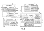
- FIG. 2 is a function block diagram of devices in the POS system 1. The configuration of the POS system 1 is described first below with reference to FIG. 1 and FIG. 2 .
- the POS (point of sale) system 1 shown in FIG. 1 includes a first printer 60 (printing device, first printing device).
- the first printer 60 is connected to a POS terminal 10 (host) that executes an application, generates documents, and outputs print instructions.
- the first printer 60 is also connected to a second printer 20 (second printer, second printing device) that prints according to the print instructions output by the POS terminal 10.
- the first printer 60 is connected through USB cable 1A to the POS terminal 10, and the second printer 20 is connected through USB cable 1B to the first printer 60. More specifically, the first printer 60 is installed between the POS terminal 10 and second printer 20. In other words, the first printer 60 and second printer 20 are connected in a daisy chain to the POS terminal 10.
- the POS terminal 10 and first printer 60 are both also connected to an in-store LAN 100.
- a third printer 30 is also connected to the in-store LAN 100, and the POS terminal 10, third printer 30, and first printer 60 can communicate with each other through the in-store LAN 100.
- the POS system 1 is used in a shopping center, department store, or other retail business, and is used to manage product marketing, product inventory, and product sales in the business.
- the POS terminal 10 is a device that runs a transaction process related to a purchase transaction by a customer and outputs transaction result information at a particular checkout counter in the business.
- a POS terminal 10 may be installed at each of plural checkout counters.
- the POS terminal 10 includes a control unit 11 that centrally controls other parts of the POS terminal 10, and a storage unit 12, input unit 13, and display unit 14 connected to the control unit 11.
- the POS terminal 10 has a LAN interface 17 or USB interface 18, or both, as interfaces for connecting external devices.
- the control unit 11 includes a CPU and memory such as RAM or ROM, and controls other parts of the POS terminal 10 and executes the functions of a POS terminal 10 by running a program stored in the storage unit 12.
- the control unit 11 has an application execution unit 11A and device driver execution unit 11B.
- the application execution unit 11A runs a POS application program and executes a transaction process and receipt printing function.
- the device driver execution unit 11B runs a device driver program and controls a printer connected through the LAN interface 17 or USB interface 18.
- the storage unit 12 stores the programs executed by the control unit 11 and data related to those programs.
- the input unit 13 connects to an input device such as a keyboard for operating the POS terminal 10, and outputs data input from the input device to the control unit 11.
- the display unit 14 has an LCD or other type of display screen, and displays data processed by the control unit 11 and the operating status of the POS terminal 10, for example.
- the display unit 14 could include a customer display that displays the purchased products and price information for the customer when the POS terminal 10 executes the transaction process.
- the LAN interface 17 has an Ethernet (R) connector or IEEE 802.11 wireless communication circuit, connects to the in-store LAN 100, and sends and receives data with other devices over the in-store LAN 100.
- the USB interface 18 includes a USB connector and interface circuit conforming to the USB standard, and handles data communication with the second printer 20 and first printer 60. A barcode scanner, magnetic card reader, electronic cash drawer, or other devices can connect to the USB interface 18, but are not shown in the figure.
- the application execution unit 11A executes a transaction process related to a product sale based on information input from the input unit 13 or a barcode scanner connected to the USB interface 18, for example.
- the transaction process includes registering the products purchased by a customer, calculating the total price, registering the amount received, and calculating the amount of change due.
- Information read from the product barcode, or a product code is input during the transaction process.
- the application execution unit 11A queries the store server 101 based on the input information, and acquires the product name and product price from a product database (not shown in the figure) maintained on the store server 101.
- the application execution unit 11A outputs data to be printed and a print instruction to print a receipt for the transaction after the transaction process is completed.
- the application execution unit 11A sends the result of the transaction process and/or data compiling the results of transaction processes during a specific period of time through the in-store LAN 100 to the store server 101.
- the store server 101 acquires the data sent by the POS terminal 10, acquires and compiles data sent by each POS terminal 10 when a plurality of POS terminals 10 are connected to the store server 101, and stores the data in a storage device not shown.
- the store server 101 could also send the stored data to the data center server 111 at predetermined times.
- the device driver program run by the device driver execution unit 11B is compatible with the device connected through the LAN interface 17, or the device connected through the USB interface 18. More specifically, the device driver execution unit 11B in this embodiment is compatible with the second printer 20, and runs a device driver program that causes the second printer 20 to print a receipt.
- the device driver execution unit 11B acquires the print instruction and data output by the application execution unit 11A, generates a print command and print data for printing the output data according to the received print instruction, and outputs the print command and print data to an external device.
- the interface to which the target device (the device to control) is connected is set in the device driver execution unit 11B.
- the device driver execution unit 11B outputs the print command and print data to the LAN interface 17 or USB interface 18, and more specifically to the interface to which the second printer 20 is connected.
- the second printer 20 is connected through the first printer 60 to the USB interface 18.
- the USB interface 18 sends the print command and print data output from the device driver execution unit 11B through the first printer 60 to the second printer 20 using the USB protocol.
- the second printer 20 includes a USB interface 22 and a second printer control unit 24 that receives commands through the USB interface 22.
- the second printer control unit 24 receives print command and print data through the USB interface 22, and executes the received print command and controls the second printer print unit 25 to print.
- the second printer control unit 24 also sends status information describing the current operating status from the USB interface 22 when printing is successful, when an error occurs, and when a status report request is received from the USB interface 22.
- the second printer print unit 25 includes a printhead 26, paper feed motor 27, and cutter unit 28.
- the printhead 26 forms characters and images on roll paper, cut-sheet paper, or other print medium as controlled by the second printer control unit 24.
- the paper feed motor 27 conveys the print medium as controlled by the second printer control unit 24.
- the cutter unit 28 cuts the print medium as controlled by the second printer control unit 24.
- the second printer 20 is a thermal printer with a thermal printhead that applies heat to thermal paper as the printhead 26.
- the second printer control unit 24 determines if data (text data) that specifies the characters to be printed using character codes is included in the print data received by the USB interface 22. If character code data is found, the second printer control unit 24 reads the font data corresponding to the character codes from a storage unit (second printer storage unit) not shown of the second printer 20, and controls the second printer print unit 25 to print.
- the device driver execution unit 11B generates the print data according to the specifications of the second printer 20 as described above. As a result, the device driver execution unit 11B generates and outputs print data containing the character codes of the characters to print to the USB interface 18 when characters are contained in the data output by the application execution unit 11A.
- the POS system 1 also has a dedicated third printer 30 for printing coupons.
- the third printer 30 has a LAN interface 33 that connects to the in-store LAN 100, and a third printer control unit 34 that receives print data sent by the POS terminal 10 through the LAN interface 33.
- the third printer 30 is a printer that prints coupons based on received print data.
- the third printer 30 receives print data sent by the POS terminal 10 to the third printer 30, analyzes the text data (character codes) contained in the received print data, and determines if a predetermined character or string is contained in the text data. If the predetermined character or string is detected, the third printer control unit 34 accesses the store server 101 through the LAN interface 33, and retrieves data for printing a coupon related to the detected character or string.
- the third printer control unit 34 prints the coupon print data acquired from the store server 101 with the print unit 35.
- the print unit 35 includes a printhead 36, paper feed motor 37, and cutter unit 38.
- the printhead 36 prints characters and images on roll paper, cut-sheet paper, or other print medium as controlled by the third printer control unit 34.
- the paper feed motor 37 conveys the print medium as controlled by the third printer control unit 34.
- the cutter unit 38 cuts the print medium as controlled by the control unit 34.
- the first printer 60 includes a first printer print unit 71 (print unit), print operation control unit 70 (print control unit), and data processing unit 61 (first printer data processing unit).
- the first printer print unit 71 prints on roll paper or cut-sheet paper.
- the print operation control unit 70 controls the printing operation of the first printer print unit 71.
- the data processing unit 61 includes a control unit 62 (printer control unit), a LAN interface 63, a USB interface 64, a storage unit 65 (first printer storage unit), and a communication unit 69 (first printer communication unit).
- the first printer control unit 62 includes CPU, RAM, ROM, and other peripheral circuits and controls parts of the first printer 60 by running a program stored in the storage unit 65.
- the LAN interface 63 has an Ethernet (R) connector or IEEE 802.11 wireless communication circuit, connects to the in-store LAN 100, and sends and receives data with other devices over the in-store LAN 100.
- the LAN interface 63 also has a plurality of connectors 63A, 63B, and can exchange data with each of the other devices connected to the connectors. In this embodiment, for example, the LAN interface 63 exchanges data with the POS terminal 10, third printer 30, store server 101, and other devices connected through the in-store LAN 100 as controlled by the communication unit 69.
- the LAN interface 63 also functions as a network hub with a relay function, and can output data received through either connector 63A, 63B to the other connector.
- the USB interface 64 includes a USB connector and interface circuit conforming to the USB standard, and handles data communication with the POS terminal 10.
- the USB interface 64 has a plurality of USB connectors that can connect a USB cable, and in this embodiment has two connectors 64A, 64B.
- connector 64A is a type-B female connector (receptacle) with the shape and pins specified by the USB standard for a target device connector, and can connect to a standard USB cable.
- the USB interface 64 has the functions of a USB device controller that operates as a target device as defined in the USB standard.
- the USB interface 64 reports the USB device class ID and device ID to the device connected through a USB cable to connector 64A, and communicates according to the control data sent from the connected device.
- the connector 64A may be a mini-USB B-connector or a micro-USB B-connector.
- the other connector 64B of the USB interface 64 is a type-A female connector with the shape and pins specified by the USB standard for a host device connector, and can connect to a standard USB cable.
- the USB interface 64 has the functions of a USB host controller that operates as a host device as defined by the USB standard. When a device classified as a target device by the USB standard is connected to connector 64B, the USB interface 64 operates as a host to the connected device, and can recognize the device and communicate with the device.
- the connector 64B may be a mini-USB A-connector or a micro-USB A-connector. The number of connectors 64B in the USB interface 64 is not specifically limited.
- a target device as used herein is an input/output device that connects to a device operating as a host, outputs data to the host as controlled by the host, or outputs data input from the host.
- a host as used herein is a computer or other control device that sends commands controlling the I/O devices to the I/O devices operating as target devices.
- the USB interface 64 functions as a connection unit connected to the POS terminal 10 and second printer 20 in this embodiment.
- the POS terminal 10 is connected to the first printer 60 through the in-store LAN 100
- the second printer 20 is connected to the first printer 60 through the USB interface 64
- the LAN interface 63 and USB interface 64 function as connection units.
- the first printer control unit 62 acquires a print command and print data through the LAN interface 63 or USB interface 64, whichever is used as the connection interface. Based on the acquired print data, the first printer control unit 62 outputs data for printing to the print operation control unit 70.
- the print operation control unit 70 controls the first printer print unit 71 based on the print data output by the first printer control unit 62, and prints on the roll paper, cut-sheet paper, or other print medium.
- the print operation control unit 70 and first printer print unit 71 together embody a second printing device.
- the first printer print unit 71 includes a printhead 72 that forms characters and images on the print medium, a paper feed motor 73 that conveys the print medium, and a cutter unit 74 that cuts the print medium, and these units operate as controlled by the print control unit 70 (first printer print control unit).
- the data processing unit 61 may be an inkjet printer or thermal printer, for example.
- the first printer 60 is an inkjet printer
- the first printer 60 has an inkjet printhead 72 that ejects four colors of ink, CMYK, onto the printing surface of the print medium to form characters and images.
- the printhead 72 could be a printhead that uses two colors of ink, red and black, or a printhead that uses the four CMYK colors plus additional colors of ink.
- the printhead 72 is a thermal head that applies heat to the printing surface of the print medium.
- the first printer 60 When configured as an inkjet printer, the first printer 60 is suited to printing graphic data (image data). In this embodiment the first printer control unit 62 generates image data by page unit specifying the position, size, and color of the characters and images printed on the print medium, and outputs this image data to the print control unit 70. When the first printer 60 is a thermal printer, the first printer 60 is suited to printing text data. In this embodiment the first printer control unit 62 outputs data containing the character codes of the characters to print on the print medium to the print operation control unit 70. The print operation control unit 70 then reads the font data corresponding to the character codes from a storage unit not shown of the print operation control unit 70, and controls the first printer print unit 71 to print.
- the first printer control unit 62 has a print data acquisition unit 62A that acquires print data, and a detection unit 62B that detects errors in the second printer 20 and print operation control unit 70.
- the first printer control unit 62 also has an error control unit 62C that controls sending an error report to the POS terminal 10 when the detection unit 62B detects an error, and an output unit 62E that outputs print commands and print data.
- the print data acquisition unit 62A acquires the print commands and print data sent by the POS terminal 10 to the second printer 20.
- the print data acquisition unit 62A receives and acquires the print data input to the USB interface 64 through the communication unit 69.
- the print data acquisition unit 62A can receive by means of the communication unit 69 print data sent by the POS terminal 10 over the network to another printer.
- the communication unit 69 controls the LAN interface 63, and can also receive other data than data addressed to the network address assigned to the LAN interface 63.
- the communication unit 69 extracts the print data sent to the target printer from the received data.
- the print data acquisition unit 62A temporarily stores the print command and print data sent from the POS terminal 10 to the storage unit 65, and passes the data to the second printer 20.
- the print data acquisition unit 62A has a function for acquiring new print data based on the print data received by the communication unit 69. More specifically, the print data acquisition unit 62A can acquire print data for a coupon based on the receipt print data sent by the POS terminal 10 to the second printer 20. For example, the print data acquisition unit 62A interprets the text data (character codes) contained in the print data sent from the POS terminal 10, and detects a predetermined character or string from this text data. When the predetermined character or string is detected, the print data acquisition unit 62A controls the communication unit 69, accesses the store server 101 through the LAN interface 63, and acquires data for printing based on the detected character or string.
- the print data acquired by the print data acquisition unit 62A here is print data for a coupon.
- the detection unit 62B receives the error report. By receiving this error report, the detection unit 62B detects an error in the second printer 20.
- the detection unit 62B also communicates command data with the print operation control unit 70, and receives an error report output by the print operation control unit 70 when an error occurs in the first printer print unit 71 or the control operation of the print operation control unit 70. By receiving this error report, the detection unit 62B detects an error in the print operation control unit 70.
- the format of the error report output by the print operation control unit 70 is not specifically limited.
- the first printer control unit 62 exchanges a control signal or control data with the print operation control unit 70 to detect the operating status of the print operation control unit 70.
- the control signals or control data communicated between the first printer control unit 62 and print operation control unit 70 at a specific time interval or specific time are also a type of error report, for example.
- the detection unit 62B detects an error
- the error control unit 62C determines whether or not to send the error report to the POS terminal 10.
- a condition for sending an error report to the POS terminal 10 is preset for the error control unit 62C. In this embodiment, an error report is sent to the POS terminal 10 when an error is detected in the second printer 20, or an error report is sent to the POS terminal 10 when an error is detected in the print operation control unit 70.
- the error control unit 62C also determines if the print unit in which the detection unit 62B detected an error is in the second printer 20 or the print operation control unit 70. The error control unit 62C then controls the communication unit 69 based on the result to send the error report from the USB interface 64 to the POS terminal 10. This error report could relay the error report received from the second printer 20 through the USB interface 64, for example. Alternatively, the error report could be a command generated by the error control unit 62C based on a command received from the second printer 20.
- the first printer 60 has a mechanical assembly embodying the first printer print unit 71, a main circuit board (print control board) not shown to which the print operation control unit 70 is disposed, and the data processing unit 61 as a discrete circuit board separate from the main circuit board. More specifically, the first printer control unit 62, LAN interface 63, USB interface 64, storage unit 65, and communication unit 69 are mounted on a circuit board separate from the main board, and connect to the print operation control unit 70 through an inter-board interface.
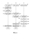
- FIG. 3 is a sequence diagram showing the operation of parts of the POS system 1, column (A) showing the operation of the POS terminal 10, (B) showing the operation of the first printer 60, and (C) showing the operation of the second printer 20.
- FIG. 3 describes operation when an error is detected while the second printer 20 prints a receipt.
- the application execution unit 11A executes a transaction process by running a POS application program and outputs a print instruction for a receipt (step S11)
- the device driver execution unit 11B generates a print command and print data (step S12).
- This print command and print data is a command and data for the second printer 20.
- the device driver execution unit 11B outputs the generated print command and print data from the USB interface 18 to the first printer 60 (step S13).
- the print data acquisition unit 62A of the first printer 60 then receives the print command and print data sent from the POS terminal 10 through the communication unit 69 and USB interface 64, and temporarily stores the received command and data in the storage unit 65 (step S21).
- the output unit 62E sends the print command and print data stored in the storage unit 65 from the USB interface 64 to the second printer 20 (step S22).
- the second printer control unit 24 of the second printer 20 receives the print command and print data from the first printer 60 through the USB interface 22 (step S31), and prints a receipt (step S32).
- the second printer control unit 24 sends an error report, which is a command indicating that an error occurred, from the USB interface 22 (step S34).
- Errors occurring in the second printer 20 include, for example, running out of paper, overheating, or a mechanical problem in the print unit 25, and software errors in the second printer control unit 24.
- the detection unit 62B of the first printer 60 receives the error report sent by the second printer 20 from the USB interface 64 (step S23), and detects that an error occurred in the second printer 20.
- the error control unit 62C determines whether to send an error report to the POS terminal 10, and because the second printer 20 is a printer configured to report errors, sends an error report to the POS terminal 10 through the USB interface 64 (step S24). The POS terminal 10 then receives the error report through the USB interface 18 (step S14), and reports the error to the operator of the POS terminal 10.
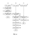
- FIG. 4 is a sequence diagram showing the operation of parts of the POS system 1, column (A) showing the operation of the POS terminal 10, (B) showing the operation of the first printer 60, and (C) showing the operation of the second printer 20.
- FIG. 4 describes operation when an error is detected while the print operation control unit 70 prints a coupon.
- the application execution unit 11A of the POS terminal 10 first runs a POS application program and outputs a print instruction for a receipt (step S11).
- the device driver execution unit 11B then generates a print command and print data for the second printer 20 (step S12).
- the device driver execution unit 11B then outputs the generated print command and print data from the USB interface 18 to the first printer 60 (step S13).
- the print data acquisition unit 62A of the first printer 60 then receives the print command and print data sent from the POS terminal 10, and temporarily stores the received command and data in the storage unit 65 (step S21).
- the output unit 62E then sends the print command and print data stored by the print data acquisition unit 62A in the storage unit 65 to the second printer 20 (step S22).
- the second printer control unit 24 of the second printer 20 receives the print command and print data from the first printer 60 through the USB interface 22 (step S31), and prints a receipt (step S32).
- the print data acquisition unit 62A of the first printer 60 also analyzes the print data stored in the storage unit 65 (step S41), accesses the store server 101, and gets data for printing a coupon (step S42).
- the print operation control unit 70 controls the first printer print unit 71, and starts printing the acquired coupon print data (step S43). If an error occurs in the print operation control unit 70 or first printer print unit 71, the print operation control unit 70 outputs an error report to the detection unit 62B, and the detection unit 62B detects the print operation control unit 70 error (step S44).
- a print operation control unit 70 error includes, for example, running out of paper or ink, or a mechanical problem, in the first printer print unit 71, and software errors in the print operation control unit 70.
- the error control unit 62C determines whether or not to send an error report to the POS terminal 10. Because the first printer 60 is not a printer configured to report errors, the process ends without sending an error report to the POS terminal 10.
- the first printer control unit 62 could substitute a different printer to print in place of the intended printer ("substitute printing" below).
- Substitute printing is an operation whereby a different printer prints instead of the print unit in which an error occurred, that is, instead of the second printer 20 or print operation control unit 70.
- the detection unit 62B detects an error in the second printer 20
- the receipt can be printed by the print operation control unit 70.
- the output unit 62E outputs to the print operation control unit 70 the print commands and print data sent by the POS terminal 10 to the second printer 20.
- the printout to be produced by the second printer 20 is printed by the first printer print unit 71 instead.
- the first printer control unit 62 could also control the third printer 30 to print a receipt intended for printing by the second printer 20.
- the first printer control unit 62 sends the print command and print data sent by the POS terminal 10 to the second printer 20 to the third printer 30 by means of the output unit 62E.
- the third printer 30 receiving this print command and print data then drives the print unit 35 to print the receipt.
- the first printer control unit 62 preferably already knows the network address of the third printer 30 on the in-store LAN 100, for example. A receipt can thus be printed even when an error is detected in both the second printer 20 and the print operation control unit 70.
- the first printer control unit 62 can also control substitute printing when the detection unit 62B detects an error in the print operation control unit 70 or first printer print unit 71. In this event, the printout that the print operation control unit 70 should print with the first printer print unit 71 can be printed by the second printer 20 or third printer 30 instead.
- sending error reports to the POS terminal 10 is optional.
- a configuration that does not send an error report to the POS terminal 10 when the print operation control unit 70 or third printer 30 substitute prints a receipt before an error report is sent to the POS terminal 10 in step S24 in FIG. 3 (B) is conceivable.
- an error report could be sent to the POS terminal 10 when the operation of substituting another printer for the second printer 20 to print a receipt fails.
- an error report could be sent from the first printer 60 to the POS terminal 10 regardless of whether the operation of substituting another printer for the second printer 20 to print a receipt succeeds or fails.
- the first printer 60 could send an error report to the POS terminal 10 after a specific time passes from when the third printer 30 or print operation control unit 70 prints a receipt.
- the first printer 60 in this POS system 1 includes a LAN interface 63 and USB interface 64 as connection units, a first printer print unit 71, a print operation control unit 70, a detection unit 62B, and an error control unit 62C.
- a POS terminal 10 that outputs data, and a second printer 20 that prints data and outputs error reports, are connected to the LAN interface 63 and USB interface 64.
- the first printer print unit 71 prints based on data output by the POS terminal 10.
- the print operation control unit 70 outputs information related to the first printer print unit 71.
- the detection unit 62B detects error reports output by the second printer 20 and error reports output by the print operation control unit 70.
- the error control unit 62C controls the information output to the POS terminal 10 based on an error report output by the second printer 20 or an error report output by the first printer print unit 71 detected by the detection unit 62B.
- the first printer 60 controls whether or not to output an error report to the POS terminal 10 appropriately to the second printer 20 or print operation control unit 70. Outputting error reports can thus be controlled according to how the first printer 60 and second printer 20 are controlled by the POS terminal 10. Because the control function of the POS terminal 10 therefore does not need to completely match the information output by the first printer 60 and second printer 20, the configuration related to the first printer 60 can be changed without changing the configuration of the POS terminal 10, for example.
- the error control unit 62C When the detection unit 62B detects an error report output by the second printer 20, the error control unit 62C outputs the error report from the second printer 20 to the POS terminal 10.
- the POS terminal 10 can control and manage printing by the second printer 20. More specifically, of the first printer print unit 71 and second printer 20 that print based on data output by the POS terminal 10, the POS terminal 10 can precisely control the second printer 20, the printing operation of which is controlled and managed by the POS terminal 10.
- the POS terminal 10 therefore does not need to control and manage the printing operation for the printing function of the first printer 60. More specifically, there is no need to change the configuration of the POS terminal 10 so that the POS terminal 10 can control and manage the first printer 60 in order to use the first printer 60.
- the first printer 60 can therefore be connected and used with the POS terminal 10 without changing the configuration of the POS terminal 10, for example.
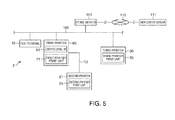
- FIG. 5 is a block diagram showing the configuration of a POS system 2 according to a second embodiment
- FIG. 6 is a function block diagram of parts of the POS system 2.
- This second embodiment describes a POS system 2 having a second printer 21 (second printing device) that prints receipts connected to the first printer 60 through a LAN cable 1D.
- the POS terminal 10 and first printer 60 are connected to the in-store LAN 100
- a third printer 30 is also connected to the in-store LAN 100, and these devices can exchange data with each other over the in-store LAN 100.
- the second printer 21 has a second printer control unit 24 and second printer print unit 25 similarly to the second printer 20 according to the first embodiment, but has a LAN interface 23 instead of a USB interface 22.
- the LAN interface 23 has a standard Ethernet (R) connector, and can exchange data with other devices through a LAN cable.
- the second printer 21 is connected through LAN cable 1D to the first printer 60, and is connected to the in-store LAN 100 by a hub function of the LAN interface 63.
- the second printer 21 operates identically to the second printer 20 ( FIG. 1 ) described above.
- the LAN cable of the in-store LAN 100 connects to connector 63A of the LAN interface 63, and LAN cable 1D connects to connector 63B.
- the POS terminal 10 sends a print command and print data from the LAN interface 17 through the in-store LAN 100 to the second printer 21.
- the print command and print data sent by the POS terminal 10 is sent to the second printer 20 through the LAN interface 63.
- Commands and data sent by the second printer 21 are sent through the LAN interface 63 to the in-store LAN 100, and received by the POS terminal 10, for example.
- the first printer control unit 62 controls the LAN interface 63, and receives and stores data sent from the POS terminal 10 to the second printer 21 in the storage unit 65.
- the first printer control unit 62 receives commands and data sent by the second printer 21 to the POS terminal 10 through the LAN interface 63. These commands and data are sent from the LAN interface 63 to the in-store LAN 100 only when transmission to the POS terminal 10 is required. The first printer control unit 62 therefore controls data communication between the POS terminal 10 and second printer 21 by means of the LAN interface 63.
- the POS system 2 operates in the same way described in FIG. 3 and FIG. 4 . More specifically, when the POS terminal 10 sends a print command and print data instructing printing a receipt to the second printer 21, the first printer 60 receives the print command and print data through the LAN interface 63 by means of the print data acquisition unit 62A. The received print command and print data are then sent from the LAN interface 63 to the second printer 21. Based on the print data received from the POS terminal 10, the print data acquisition unit 62A acquires coupon print data from the store server 101.
- the detection unit 62B detects the error.
- the error control unit 62C sends the error report from the LAN interface 63 to the POS terminal POS terminal 10 if the print unit in which an error was detected is configured to report errors, and does not send the error report to the POS terminal 10 if the print unit is not configured to send error reports.
- the present disclosure can therefore be used to achieve the same effect as the first embodiment described above when the second printer 21 is connected through a LAN cable 1D to the POS terminal 10 as in the second embodiment.
- the present disclosure is not limited to the first and second embodiments described above.
- the first and second embodiments describe using the first printer 60 in a POS system 1, 2 that uses a POS terminal 10 running a POS application program as the host device.
- the POS system 1, 2 is described as a system having a second printer 20, 21 and/or a third printer 30 connected to the POS terminal 10.
- the disclosure is not so limited, however, and can be applied to a configuration having a printer connected to a host device that runs a different data process and prints out other forms.
- the foregoing embodiments also describe configurations that send print commands and print data to printers from a POS terminal 10 as the host device.
- a mobile terminal can be used in place of the POS terminal 10, or a client could connect through a communication line to a remotely located server.
- the remote server can run an application program, and the client can send print commands and print data generated and transmitted by the server to the printers.
- the printers are also not limited to connecting to the POS terminal 10 by wire, and could connect to the POS terminal 10 wirelessly.
- the POS terminal 10, second printer 20, 21, and first printer 60 in the first and second embodiments are described as connecting through a USB interface or an in-store LAN 100 through an Ethernet connection, but the disclosure is not so limited. More particularly, the disclosure can be applied to any configuration using any interface enabling data communication between plural devices.
- the second printer print unit 25, the third printer print unit 35, and the first printer print unit 71 in the first and second embodiments are described as printing to cut-sheet paper or roll paper.
- the print units are not limited to a particular printing method, however, and a thermal printer, inkjet printer, dot impact printer, laser printer, or other type of printer may be used. Of the function blocks shown in the FIG. 1 , FIG. 2 , FIG. 5 , and FIG.
- parts including at least the control units can be achieved through the cooperation of hardware and software, and do not suggest a specific hardware configuration.
- a configuration that executes the operations including the operations shown in the accompanying sequence diagrams can also be embodied by these parts executing a program stored on an externally connectable non-transitory storage medium.
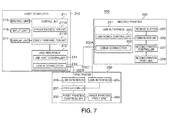
- FIG. 7 shows the configuration of a printing system 200 according to a third embodiment of the disclosure.
- the printing system 200 shown in FIG. 7 includes a first printer 230 (printing device, first printing device), a host computer 210 (host), and second printer 220 (second printing device).
- the first printer 230 is installed between the host computer 210 and second printer 220.
- the host computer 210 runs an application program, generates documents, and outputs print commands.
- the second printer 220 prints according to the print commands output by the host computer 210.
- the host computer 210 and second printer 220 can also be directly connected 1:1 through a USB cable 200A. When connected directly, the second printer 220 directly receives commands and data output by the host computer 210 and prints.
- This printing system 200 is constructed based on a system having the host computer 210 directly connected to the second printer 220 through a USB cable 200A. More specifically, the USB cable 200A is disconnected and the first printer 230 is connected to the host computer 210 through USB cable 200B. The first printer 230 and the second printer 220 are then connected to each other through USB cable 200C, creating the printing system 200. The first printer 230 and second printer 220 are thus daisy chained to the host computer 210 in this printing system 200.
- the host computer 210 includes a control unit 211, a storage unit 215, an input unit 216, and a display unit 217.
- the host computer 210 also has a USB interface 212 as an interface to which external devices connect.
- the USB interface 212 includes a USB-A connector 213, and a USB host controller 214 that handles communication with the device connected through a USB cable to the USB-A connector 213 according to a specific protocol.
- the control unit 211 includes a CPU and memory such as RAM or ROM, and centrally controls other parts of the host computer 210 by running a program stored in the storage unit 215.
- the application execution unit 211A of the control unit 211 executes an application program stored in the storage unit 215.
- the control unit 211 runs a POS application program and operates as a POS terminal.
- the control unit 211 executes a data process related to a product sale based on data input by the input unit 216, and outputs data for printing a receipt showing the result of the product sale process together with an instruction to print.
- the control unit 211 also has a device driver execution unit 211B.
- the device driver execution unit 211B runs a device driver program stored in the storage unit 215, and controls devices connected to the host computer 210.
- the host computer 210 in this embodiment of the disclosure corresponds to a device that connects through a USB interface 212, and can execute the device driver program with the device driver execution unit 211B.
- the device driver execution unit 211B generates print data and print commands causing the printer to print based on the print instructions and data output by the application execution unit 211A, and outputs through the USB interface 212.
- a device driver that outputs print instructions and data to the second printer 220 is installed to the host computer 210 in this embodiment.
- USB interface 212 and the USB interfaces 221, 240, 245 described below render the physical layer, link layer, and protocol layers defined by the USB standard, and enable serial data communication between devices connected 1:1.
- the USB standard as used herein includes USB 1.1 to USB 3.0 and future versions and extensions.
- the USB-A connector 213 of the USB interface 212 is a female connector (receptacle) with the shape and pins specified by the USB standard for a connector of the device on the host side.
- Standard USB cables 200A and 200B can connect to the USB-A connector 213.
- the USB-A connector 213 may be a mini-A or a micro-A USB connector. This also applies to the USB-A connector 246 ( FIG. 8 ) described below.
- the number of USB-A connectors 213 disposed to the USB interface 212 is not specifically limited.
- the USB host controller 214 operates as the host to this device, and can recognize the device and communicate with the device.
- a device as used herein is, for example, an input/output (I/O) device that connects to another device operating as the host, and outputs data to the host as controlled by the host, or outputs data input from the host.
- the host is, for example, a computer that sends commands for controlling I/O devices to the connected I/O devices.
- the second printer 220 is a device that has a second printer print unit 228 (second print unit) that includes a printhead, paper feed motor, conveyance rollers, and cutter unit not shown, and prints (records) text and images on cut-sheet paper, roll paper, or other print medium.
- the second printer 220 includes a USB interface 221 (communication unit), communication unit 226, and second printer controller 227.
- the communication unit 226 exchanges data with the device connected through the USB interface 221.
- the second printer controller 227 controls the second printer print unit 228 and prints based on data received by the communication unit 226.
- the USB-B connector 222 of the USB interface 221 is a female connector with the shape and pins specified by the USB standard for a connector on the target device side.
- Standard USB cables 200A and 200C can connect to the USB-B connector 222.
- the USB-B connector 222 may be a mini-B or a micro-B USB connector. This also applies to the USB-B connector 241 ( FIG. 8 ) described below.
- the USB device controller 223 operates as a USB target device as defined by the USB standard. The USB device controller 223 reports its USB device class ID and device ID to the device connected through a USB cable to the USB-B connector 222, and communicates according to the control data sent from the connected device.
- the communication unit 226 receives commands and data through the USB interface 221 and temporarily stores the commands and data in the communication buffer 225.
- the communication unit 226 also transmits control commands and data about the status of the second printer 220 through the USB interface 221.
- the second printer controller 227 reads and executes the commands stored in the communication buffer 225 in the order received. For example, when the second printer controller 227 reads a command requesting a status transmission from the communication buffer 225, the second printer controller 227 generates and sends status information describing the operating status of the second printer 220 from the communication unit 226.
- the second printer controller 227 controls the second printer print unit 228 and prints according to the command.
- the second printer controller 227 then generates a completion report indicating that printing ended, or an error report indicating that an error occurred, and transmits the report by means of the communication unit 226 from the USB interface 221.
- the first printer 230 has two USB interfaces 240, 245.
- the host computer 210 connects to the USB interface 240 through USB cable 200B.
- the second printer 220 connects to the other USB interface 245 through USB cable 200C.
- the first printer 230 includes a communication control unit 231 that controls communication through the USB interfaces 240, 245.
- the first printer 230 also has and prints by means of a first printer print unit 260 (print unit, first print unit) including a printhead, paper feed motor, conveyance rollers, and cutter unit not shown.
- the first printer 230 also has a first printer controller 232 (print control unit) that controls the first printer print unit 260 and prints based on data communicated by the control unit 231.
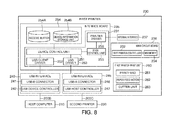
- FIG. 8 is a function block diagram of the printing system 200 showing the configuration of the first printer 230 in detail.
- USB interface 240 connection unit
- USB device controller 241 includes a USB-B connector 241 and a USB device controller 242.
- the USB interface 245 includes a USB-A connector 246 and a USB host controller 247.
- USB-B connector 241 is a female connector with the shape and pins specified by the USB standard for a target device connector, and connects to USB cable 200B.
- USB-A connector 213 USB-A connector 246 is a female connector with the shape and pins specified by the USB standard for a host connector.
- USB cable 200C connects to USB-A connector 246.
- the number of USB-A connectors 246 in the USB interface 245 is not specifically limited.
- the USB device controller 242 reports its USB device class ID and device ID to the device connected to the USB-B connector 241, and communicates according to the control data sent from the connected device.
- the USB host controller 247 operates as the host device for the connected USB device.
- the USB host controller 247 can recognize the connected device and communicate with the device. More specifically, the first printer 230 operates as a USB target device relative to the device connected to USB interface 240 (the host computer 210 in this embodiment), and operates as a host relative to the device connected to USB interface 245 (the second printer 220 in this embodiment).
- the control unit 231 includes a device control unit 251, USB client driver 252, USB driver 253, print control unit 255, and printer driver 256.
- the control unit 231 includes CPU, RAM, ROM, and other peripheral circuits not shown mounted on the interface board 235, and parts of the control unit 231 are achieved as software constructions as a result of the CPU running a control program.
- the interface board 135 also has a storage unit 254 connected to the control unit 231.
- the storage unit 254 includes flash ROM mounted on the interface board 235, for example.
- a receive buffer 254A (print data storage unit) and device information storage unit 254B (storage unit) are created in the storage space of the storage unit 254.
- the receive buffer 254A sequentially stores the received commands and data.
- the device information storage unit 254B stores the USB device information (device information) that the control unit 231 sends to the host computer 210.
- the control unit 231 functions as a USB client driver 252 by executing a specific driver program.
- the USB client driver 252 operates as a USB device conforming to the USB standard relative to the host computer 210 connected to the USB interface 240.
- the USB client driver 252 reports device information from the device connected to the USB interface 240.
- USB device information includes the USB device class ID and device ID.
- the USB client driver 252 responds to the request by sending the USB device information. Reporting the USB device information enables data communication between the devices.
- the USB client driver 252 sends the USB device information to the host computer 210.
- the USB client driver 252 can output USB device information including the vendor ID of the first printer 230 manufacturer, and the device ID corresponding to the model of the first printer 230.
- the USB client driver 252 can also output USB device information containing the vendor ID of the second printer 20 manufacturer and the device ID corresponding to the model of the second printer 20 when this information is preset.
- the first printer 230 stores the USB device information (first device information) of the first printer 230, and the USB device information (second device information) of the second printer 20, in the device information storage unit 254B.
- the device control unit 251 detects when the host computer 210 is connected to the USB interface 240, and outputs the USB device information for the second printer 220 stored in the storage unit 254 to the USB client driver 252 according to the previous set information.
- the USB client driver 252 reports the USB device information to the host computer 210.
- the host computer 210 recognizes that the second printer 220 is connected to the USB-A connector 223 ( FIG. 7 ).
- the host computer 210 operates in the same way as when connected to the second printer 220 through USB cable 200A ( FIG. 7 ) even though the host computer 210 is connected to the first printer 230 through USB cable 200B.
- the control unit 231 functions as a USB driver 253 by running a specific device driver program.
- the USB driver 253 uses the USB host controller 247 and operates as a host device as defined by the USB standard for the device connected to the USB interface 245, and can recognize and communicate with the connected device.
- the USB driver 253 is a device driver for the second printer 220, and functions to generate and output print commands and print data for the second printer 220.
- the USB driver 253 requests transmission of the USB device information from the second printer 220.
- the USB driver 253 thus acquires the information sent by the second printer 220 in response to this request.
- the USB driver 253 then enters a state enabling communication with the second printer 220. In this event, the second printer 220 operates in the same way as when connected directly to the host computer 210 through USB cable 200A ( FIG. 7 ).
- the device control unit 251 When a print command and print data are output from the host computer 210 connected to USB interface 240, the device control unit 251 stores the commands and data in the receive buffer 254A created in the storage unit 254. The device control unit 251 outputs the commands and data stored in the receive buffer 254A to the print control unit 255, and outputs to the second printer 220 by means of the USB driver 253. As a result, the commands and data sent by the host computer 210 are transmitted to the second printer 220.
- the first printer 230 functions as a host device for the second printer 220 by means of the USB interface 245.
- the second printer 220 operates according to these commands and data in the same way as when commands and data sent directly from the host are received. In other words, the second printer 220 receives the commands and data and prints in the same way as when the host computer 210 is connected to the USB interface 221 through USB cable 200A.
- the first printer 230 has a main circuit board 136 (print control board) and an interface board 235.
- the first printer controller 232 that controls the first printer print unit 260 is mounted on the main circuit board 236.
- the interface board 235 can be removably installed to the first printer 230 separately from the main circuit board 236.
- the control unit 231, memory 233, and USB interfaces 240, 245 are mounted on the interface board 235.
- the parts packaged on the interface board 235, and the first printer controller 232 disposed to the main circuit board 236, are connected so that they can exchange data with each other through an internal interface 237 in the first printer 230.
- Memory 234 connects to the first printer controller 232.
- Memory 234 is a storage unit that temporarily stores commands and data.
- the first printer print unit 260 includes a printhead 261, paper feed motor 262, and cutter unit 263.
- the first printer print unit 260 prints as controlled by the first printer controller 232. More specifically, the first printer print unit 260 conveys the cut-sheet paper, roll paper, or other print medium with the paper feed motor 262, prints a character or image with the printhead 261, and cuts the printed print medium with the cutter unit 263.
- the print control unit 255 determines if the first printer 230 matches the condition for printing based on the commands and data input from the device control unit 251. If the condition is met, the print control unit 255 generates a print command and print data, and outputs to the printer driver 256. The print control unit 255 detects, for example, if a predetermined specific string is contained in the print data sent from the host computer 210. If the specific string is detected, the print control unit 255 outputs the print command and print data previously stored in the storage unit 254 linked to that string to the first printer controller 232.
- the print control unit 255 determines if a predetermined specific product name or product classification data is contained in the print data. If the product name or product classification data is contained in the print data, the print control unit 255 outputs a print command and print data for printing a previously stored coupon to the printer driver 256.
- the printer driver 256 is a device driver that drives the first printer print unit 260 and main circuit board 236 of the first printer 230, and is embodied by the control unit 231 executing a specific device driver program. As a result of this operation, when the host computer 210 sends commands and data for printing a receipt, the second printer 220 produces a receipt according to the received commands and data. The first printer 230 also prints a coupon related to the receipt.
- the host computer 210 and second printer 220 can also operate in the same way as when they are connected directly to each other through USB cable 200A.
- the first printer 230 can also be installed without modifying the application program or device driver program that run on the host computer 210, and without changing an operating condition of the second printer 220.
- the first printer 230 is connected between the host computer 210 and second printer 220, and has a function for relaying data between the host computer 210 and second printer 220.
- the second printer 220 can also print receipts the same way as before the configuration of the printing system 200 was changed, while the first printer 230 can also print coupons related to the printed receipt.
- FIG. 9 is a sequence diagram showing the operation of parts of the printing system 200, column (A) showing the operation of the host computer 210, and (B) showing the operation of the first printer 230.
- the operation shown in FIG. 9 is executed when the host computer 210 and first printer 230 are connected through USB cable 200B.
- the host computer 210 detects connection of a device to the USB-A connector 213 (step S111)
- the host computer 210 operates as a host device to the connected device, and requests the USB device information (step S112).
- the device control unit 251 of the first printer 230 detects connection of a device to the USB interface 240 (step S121)
- the device control unit 251 operates as a (target) device.
- the device control unit 251 receives a request for USB device information sent from the host computer 210 (step S122). The device control unit 251 then reads the USB device information for the second printer 220 stored in the device information storage unit 254B, and sends the information to the host computer 210 (step S123). The host computer 210 receives the USB device information sent from the first printer 230 (step S113). The host computer 210 then uses the device driver execution unit 211B to execute the device driver program corresponding to the received USB device information (step S114). The host computer 210 and first printer 230 then communicate with each other through USB cable 200B (steps S115, S124) and open a command and data communication link therebetween. After the operation shown in FIG. 9 , the host computer 210 recognizes the second printer 220 as the target device connected through USB cable 200B.
- FIG. 10 is a sequence diagram showing the operation of parts of the printing system 200, column (A) showing the operation of the host computer 210, (B) showing the operation of the first printer 230, and (C) showing the operation of the second printer 220.
- the operation shown in FIG. 10 is performed after the operation in FIG. 9 .
- the host computer 210 When a document is created and a print instruction is output by the operation of the application execution unit 211A (step S131), the host computer 210 generates a print command and print data based on the print instruction (step S132). In this instance the device driver execution unit 211B generates the print command and print data to operate the second printer 220.
- the host computer 210 then outputs the generated print command and print data from the USB interface 212 (step S133).
- the print command and print data sent by the host computer 210 is then received by the first printer 230 through the USB interface 240 (step S141).
- the device control unit 251 stores the print command and print data received by the USB interface 240 to the receive buffer 254A, and outputs the print command and print data from the USB interface 245 (step S142).
- the device control unit 251 also outputs the commands and data stored in the receive buffer 254A to the print control unit 255.
- the print control unit 255 analyzes the print data stored in memory 233 (step S143).
- the print control unit 255 acquires data for printing a coupon corresponding to the analyzed print data (step S144), and outputs the acquired data to the printer driver 256.
- the printer driver 256 outputs the data for printing a coupon through the internal interface 237 to the first printer controller 232, and a coupon is printed as controlled by the first printer controller 232 (step S145).
- the print control unit 255 then generates and outputs a printing success report for the second printer 220 to the host computer 210 (step S146).
- the host computer 210 receives the printing success report sent from the first printer 230 as the printing success report for the second printer 220 (step S134), and ends this process because printing ended.
- the second printer 220 receives the print command and print data sent from the first printer 230 (step S151). The second printer 220 then prints a receipt as controlled by the second printer controller 227 according to the received print command and print data (step S152).
- the first printer 230 of the printing system 200 is thus connected to a host computer 210, and has a first printer print unit 260, device information storage unit 254B, USB interface 240, and device control unit 251.
- the device information storage unit 254B stores USB device information about the first printer 230, and USB device information about the second printer 220, which is a different printer.
- the host computer 210 connects to the USB interface 240.
- the device control unit 251 outputs the USB device information of the second printer 220 to the host computer 210.
- the first printer 230 outputs the USB device information for the second printer 220 to the host computer 210, enabling the host computer 210 to recognize that the second printer 220 was connected to the host computer 210. As a result, the printer connected to the host computer 210 can be changed from the second printer 220 to the first printer 230 without changing the configuration of the host computer 210.
- the device control unit 251 When the host computer 210 outputs print commands and print data for the second printer 220, the device control unit 251 outputs those commands and data from the USB interface 245 to the second printer 220. As a result, the data output by the host computer 210 can be printed by the second printer 220.
- the printing system 200 includes a host computer 210 that outputs data, and a first printer 230 having a first printer print unit 260 that prints and a connection unit that connects to the host computer 210.
- the printing system 200 also includes a second printer 220 having a USB interface 221 that connects and communicates with the first printer 230, and a second printer print unit 228 that prints.
- the first printer 230 has a device information storage unit 254B that stores USB device information including the model (type) of the first printer 230, and USB device information including the model (type) of the second printer 220.
- the first printer 230 When the host computer 210 requests the USB device information from the first printer 230, the first printer 230 sends the USB device information for the second printer 220 stored in the device information storage unit 254B to the host computer 210. Because the first printer 230 outputs the USB device information of the second printer 220 to the host computer 210, the host computer 210 can recognize the first printer 230 as the second printer 220. As a result, the first printer 230 can be connected to a host computer 210 that is compatible with the second printer 220 without changing the configuration of the host computer 210. Therefore, the printer configuration can be changed without changing the configuration of the host computer 210 in a system having a host computer 210 and printer connected together.
- a third embodiment of the disclosure is described above, but the disclosure is not limited thereto and can obviously be modified and adapted as desired within the scope of the disclosure.
- the third embodiment describes a configuration having a host computer 210 connected to the USB interface 240 of a first printer 230, and a second printer 220 connected to another USB interface 245.
- the disclosure is not so limited, however, and the device that connects to the USB interface 240 can be any device that can operate as a host device, such as another printer or a mobile terminal device having a USB host controller.
- the device connected to the USB interface 245 is not specifically limited and can be any device that operates as a USB target device, such as a printer or other input/output device.
- the second printer print unit 228 of the second printer 220, and the first printer print unit 260 of the first printer 230 in the foregoing embodiment are described as printing to cut-sheet paper or roll paper.
- the print unit of the disclosure is not so limited, however, and a thermal printer, inkjet printer, dot impact printer, laser printer, or other type of printer may be used.
- the function blocks shown in FIG. 7 and FIG. 8 can also be achieved through the cooperation of hardware and software, and do not suggest a specific hardware configuration.
- the configuration that executes the operations including the operations shown in the flow charts in FIG. 9 and FIG. 10 can also be embodied by these parts executing a program stored on an externally connectable non-transitory storage medium.
- USB interface 240 and USB interface 245 are also not limited to being rendered as discrete hardware constructions.
- USB-B connector 241 and USB-A connector 246 can be rendered in a single hardware construction having the functions of both USB device controller 242 and USB host controller 247.
- the present disclosure is directed to solving the foregoing problem, and an object is to enable changing the printer configuration without changing the configuration of the control device in a system that controls a printer.
Abstract
Description
- The present disclosure relates to a printing device, a printing system, and a printing method.
- Systems that print receipts using a printer connected to a control (host) device such as a computer are known from the literature. See, for example, Japanese Unexamined Patent Appl. Pub.
JP-A-2009-187078 JP-A-2012-123597 JP-A-2012-123597 JP-A-2012-096503 - However, in order to print using plural printers as described in
JP-A-2012-123597 JP-A-2009-187078
Because the configuration of the control device must be changed according to the new printer configuration when the printer configuration is changed, there is a need to enable changing the printer configuration more easily. - A printing device according to an aspect of the disclosure has a print unit configured to print, a connection unit configured to connect to a host device, and a control unit configured to output information related to a different print unit than the print unit to the host device when the host device connects to the connection unit.
A first printing device with a print unit can output to the host device information related to a second printing device, which is a different printing device (external device). For example, the first printing device can be connected to a host device that is compatible with a second printing device, and the host device can be operated. As a result, the configuration related to the printing device can be changed without changing the configuration of the host device, which is a control device. - The connection unit of the first printing device is configured to connect to a different external device than the host device, the printing device includes a print control unit configured to output information related to the print unit, and a detection unit configured to detect information related to the print unit being output by the print control unit, or information output by the external device related to the different print unit than the print unit; and the control unit is configured to output information to the host device based on the information related to the print unit detected by the detection unit, or information output by the external device related to the different print unit than the print unit.
This aspect of the disclosure can detect printing-related information output by the second printing device, and information related to printing by the print unit of the printing device, and control the information output to the host device. As a result, the information output to the host device can be controlled according to how the printing device of the disclosure and the second printing device are controlled by the host device. The configuration of the printing device connected to the host device can therefore be changed without needing to change the control function of the host device according to the configuration of the printing device. - In a printing device according to another aspect of the disclosure, when the detection unit detects information output by the external device related to the different print unit than the print unit, the control unit is configured to output to the host device the information output by the external device related to the different print unit than the print unit.
When the second printing device outputs information related to printing, this aspect of the disclosure can output this information to the host device. As a result, the host device connected to the printing device can simply control and manage the printing operation of the second printing device, and making the host device compatible with the printing device of the disclosure is not necessary. The printing device of the disclosure can also be used to relay communication between the host device and the second printing device. - In a printing device according to another aspect of the disclosure, when the detection unit detects information output by the print control unit related to the print unit, the control unit does not output to the host device the information output by the print control unit related to the print unit.
When the print control unit detects information related to printing, this information is not output to the host device. Because there is therefore no need to control the printing device on the host device side, the configuration of the host device does not need to be changed so that the host device can control this print unit. The printing device can therefore be connected and used with the host device without changing the configuration of the host device. - In a printing device, the information related to the print unit is first device information including the type of the print unit, the information related to the different print unit than the print unit is second device information output by the external device including the type of the different print unit of the external device, the printing device includes a storage unit configured to store the first device information and the second device information; and the control unit is configured to output the second device information to the host device when the host device is connected to the connection unit.
The printing device connected to the host device stores device information for the second printing device, which is a different printing device, and outputs the device information for the second printing device to the host device. As a result, the printing device can be recognized as the second printing when connected to the host device. A printing device that is not compatible with the host device can therefore be connected without changing the configuration of the host device. - In a printing device, when the host device outputs data to be processed by the external device, the connection unit is configured to output the data to the external device.
Because the device connection unit outputs to the second printing device data that is output by the host device to the second printing device, the printing device can process data output by the host device and can cause the second printing device to process the data. The connection of the host device and directly connected second printing device can therefore be changed, and the printing device of the disclosure can be installed between the host device and the second printing device, without changing the function or setting of the host device and the second printing device. - The printing system includes, a host device configured to output data, a first printing device, and a second printing device being connected to the first printing device and including a second print unit configured to print, the first printing device including a first print unit configured to print, a connection unit configured to connect the host device and to the second printing device, and a control unit configured to output information related to the second printing device to the host device connected to the connection unit.
Because the first printing device can output information related to the second printing device to the host device, the first printing device can be connected to a host device that is compatible with the second printing device, and the host device can be operated. As a result, the configuration of the printing system can be changed by connecting the first printing device and second printing device, for example, without changing the configuration of the host device, which is the control device. - In this printing system, the second printing device is configured to print the data output by the host device and received via the connection unit of the first printing device with the second print unit, and to output information related to the second print unit, the first printing device includes a print control unit configured to output information related to the first print unit when printing with the first print unit based on data output by the host device, and a detection unit configured to detect information output by the print control unit related to the first print unit, or information output by the second printing device related to the second print unit, and the control unit is configured to control information output to the host device based on the information output by the print control unit related to the first print unit, or the information output by the second printing device related to the second print unit.
The first printing device detects information related to printing by the first printing device and information related to printing by the second printing device, and can control the information output to the host device. As a result, the information output to the host device can be controlled according to how the first and second printing devices are controlled by the host device. Because the control function of the host device does not need to be changed according to the configuration of the printing device, the configuration of the printing device can be changed without changing the configuration of the host device. - In a printing system, when the detection unit of the first printing device detects information output by the second printing device related to the second print unit, the control unit is configured to output information output by the second printing device related to the second print unit to the host device.
When the second printing device outputs information related to printing, this information is output from the first printing device to the host device. As a result, the host device connected to the first printing device can simply control and manage the printing operation of the second printing device, and making the host device compatible with the first printing device is not necessary. The first printing device can also be used to relay communication between the host device and the second printing device. - In a printing system, when the detection unit of the first printing device detects information output by the print control unit related to the first print unit, the control unit is configured to output the information output by the print control unit related to the first print unit to the host device.
Because information related to printing by the first printing device is not output to the host device, the host device does not need to control the first printing device. Because there is therefore no need to change the configuration of the host device to control the first printing device, the first printing device can be connected and used with the host device without changing the configuration of the host device. - In a printing system, the connection unit of the first printing device is configured to send the data output from the host device to the second printing device.
The first printing device outputs to the second printing device data that is output by the host device to the second printing device. As a result, data output by the host device can be processed by the first printing device, and the data can be processed by the second printing device. The connection of the directly connected host device and second printing device can therefore be changed, and the first printing device can be installed between the host device and second printing device, without changing the function or setting of the host device and second printing device, for example. - In a printing system, the information related to the first print unit is first device information including the type of the first print unit, the information related to the second print unit is second device information including the type of the second print unit, and the first printing device includes a storage unit configured to store the first device information and the second device information, and the control unit is configured to output the second device information stored in the storage unit to the host device when the host device requests device information from the first printing device.
The first printing device connected to the host device stores device information for the second printing device, which is a different printing device, and outputs the device information for the second printing device to the host device. As a result, the host device can be made to recognize the first printing device as the second printing device when the first printing device is connected to the host device. The first printing device can therefore be connected to and used with the host device without changing the configuration of the host device even when the host device is not compatible with the first printing device. - In a printing system, the host device is configured to send print data for processing by the second printing device to the connection unit of the first printing device; the first printing device is configured to receive the print data sent from the host device, and to send the received print data to the second printing device; and the second printing device is configured to receive the print data sent from the first printing device, and to print the received print data with the second print unit.
Because the first printing device outputs to the second printing device data that is output by the host device to the second printing device, the data output by the host device can be processed by the first printing device and also processed by the second printing device. - In a printing system, the first printing device has a data analyzing unit configured to analyze print data sent from the host device, and a print data storage unit configured to store predetermined information and print data related to the predetermined information; and the data analyzing unit is configured to determine if the predetermined information is included in the print data, and if the predetermined information is included, the first print unit is configured to print the print data related to the predetermined information.
The first printing device can be connected to a host device compatible with the second printing device without changing the configuration of the host device, and the first printing device can interpret the print data sent from the host device and print other information related to the print data. - In a printing system, the host device is a POS terminal that processes transaction information, and the second printing device prints a receipt related to the transaction information sent from the POS terminal.
The first printing device can be connected to a POS terminal without changing the configuration of the POS terminal that prints receipts using the second printing device, and a receipt printing function can be rendered by the second printing device while the first printing device executes another process. - A print control device is connected to a host device that outputs data, a first printing device that prints the data and outputs first information related to printing, and a second printing device that prints based on data output by the host device and outputs second information related to printing, and has a detection unit that detects the first information output by the first printing device and the second information output by the second printing device, and a control unit that controls information output to the host device based on the first information or second information detected by the detection unit.
When first and second printing devices that print based on data output by a host device output information related to printing, the information output to the host device can be controlled according to the first printing device and the second printing device. As a result, output of information to the host device can be controlled according to how the first and second printing devices are controlled by the host device. Because the control function of the host device therefore does not need to completely match the information output by both the first and second printing devices, the configuration related to the printing devices can be changed without changing the configuration of the host device, for example. - A printing method includes, requesting, by a host device, a first printing device for device information including the type of printing device after the host device and the first printing device are connected; sending, by the first printing device (60) that was requested for device information, device information stored for a second printing device to the host device, sending, by the host device, print data to be processed by the second printing device to the first printing device, sending, by the first printing device, the sent print data to the second printing device connected to the first printing device; and printing, by the second printing device, based on the print data.
Because the first printing device connected to the host device outputs device information for the second printing device to the host device, the host device can be made to recognize the first printing device as the second printing device. As a result, the first printing device can be connected to a host device that is compatible with a second printing device without changing the configuration of the host device. The configuration of the printing devices in a system having a host device connected to a printing device can therefore be changed without changing the configuration of the host device. -
-
FIG. 1 is a function block diagram of a POS system according to a first embodiment. -
FIG. 2 is a function block diagram of devices in the POS system. -
FIG. 3 is a sequence diagram showing an operation of parts of the first embodiment. -
FIG. 4 is a sequence diagram showing another operation of parts of the first embodiment. -
FIG. 5 is a function block diagram of a POS system according to a second embodiment. -
FIG. 6 is a function block diagram of devices in the POS system. -
FIG. 7 is a function block diagram of a printing system according to a third embodiment. -
FIG. 8 is a function block diagram of a first printer in the third embodiment. -
FIG. 9 is a sequence diagram showing an operation of the third embodiment. -
FIG. 10 is a sequence diagram showing an operation of the third embodiment. - A preferred embodiment is described below with reference to the accompanying figures.
FIG. 1 shows the general configuration of a POS system 1 (printing system) according to the first embodiment, andFIG. 2 is a function block diagram of devices in the POS system 1. The configuration of the POS system 1 is described first below with reference toFIG. 1 andFIG. 2 . - The POS (point of sale) system 1 shown in
FIG. 1 includes a first printer 60 (printing device, first printing device). Thefirst printer 60 is connected to a POS terminal 10 (host) that executes an application, generates documents, and outputs print instructions. Thefirst printer 60 is also connected to a second printer 20 (second printer, second printing device) that prints according to the print instructions output by thePOS terminal 10.
Thefirst printer 60 is connected throughUSB cable 1A to thePOS terminal 10, and thesecond printer 20 is connected throughUSB cable 1B to thefirst printer 60. More specifically, thefirst printer 60 is installed between thePOS terminal 10 andsecond printer 20. In other words, thefirst printer 60 andsecond printer 20 are connected in a daisy chain to thePOS terminal 10.
ThePOS terminal 10 andfirst printer 60 are both also connected to an in-store LAN 100. Athird printer 30 is also connected to the in-store LAN 100, and thePOS terminal 10,third printer 30, andfirst printer 60 can communicate with each other through the in-store LAN 100. - The POS system 1 is used in a shopping center, department store, or other retail business, and is used to manage product marketing, product inventory, and product sales in the business.
ThePOS terminal 10 is a device that runs a transaction process related to a purchase transaction by a customer and outputs transaction result information at a particular checkout counter in the business. APOS terminal 10 may be installed at each of plural checkout counters. - The
POS terminal 10 includes acontrol unit 11 that centrally controls other parts of thePOS terminal 10, and astorage unit 12,input unit 13, anddisplay unit 14 connected to thecontrol unit 11. ThePOS terminal 10 has aLAN interface 17 orUSB interface 18, or both, as interfaces for connecting external devices. - The
control unit 11 includes a CPU and memory such as RAM or ROM, and controls other parts of thePOS terminal 10 and executes the functions of aPOS terminal 10 by running a program stored in thestorage unit 12. Thecontrol unit 11 has anapplication execution unit 11A and devicedriver execution unit 11B. Theapplication execution unit 11A runs a POS application program and executes a transaction process and receipt printing function. The devicedriver execution unit 11B runs a device driver program and controls a printer connected through theLAN interface 17 orUSB interface 18.
Thestorage unit 12 stores the programs executed by thecontrol unit 11 and data related to those programs.
Theinput unit 13 connects to an input device such as a keyboard for operating thePOS terminal 10, and outputs data input from the input device to thecontrol unit 11.
Thedisplay unit 14 has an LCD or other type of display screen, and displays data processed by thecontrol unit 11 and the operating status of thePOS terminal 10, for example. Thedisplay unit 14 could include a customer display that displays the purchased products and price information for the customer when thePOS terminal 10 executes the transaction process.
TheLAN interface 17 has an Ethernet (R) connector or IEEE 802.11 wireless communication circuit, connects to the in-store LAN 100, and sends and receives data with other devices over the in-store LAN 100.
TheUSB interface 18 includes a USB connector and interface circuit conforming to the USB standard, and handles data communication with thesecond printer 20 andfirst printer 60. A barcode scanner, magnetic card reader, electronic cash drawer, or other devices can connect to theUSB interface 18, but are not shown in the figure. - The
application execution unit 11A executes a transaction process related to a product sale based on information input from theinput unit 13 or a barcode scanner connected to theUSB interface 18, for example. The transaction process includes registering the products purchased by a customer, calculating the total price, registering the amount received, and calculating the amount of change due. Information read from the product barcode, or a product code, is input during the transaction process. Based on the input information, theapplication execution unit 11A queries thestore server 101 based on the input information, and acquires the product name and product price from a product database (not shown in the figure) maintained on thestore server 101.
Theapplication execution unit 11A outputs data to be printed and a print instruction to print a receipt for the transaction after the transaction process is completed.
Theapplication execution unit 11A sends the result of the transaction process and/or data compiling the results of transaction processes during a specific period of time through the in-store LAN 100 to thestore server 101. Thestore server 101 acquires the data sent by thePOS terminal 10, acquires and compiles data sent by eachPOS terminal 10 when a plurality ofPOS terminals 10 are connected to thestore server 101, and stores the data in a storage device not shown. Thestore server 101 could also send the stored data to thedata center server 111 at predetermined times. - The device driver program run by the device
driver execution unit 11B is compatible with the device connected through theLAN interface 17, or the device connected through theUSB interface 18. More specifically, the devicedriver execution unit 11B in this embodiment is compatible with thesecond printer 20, and runs a device driver program that causes thesecond printer 20 to print a receipt. The devicedriver execution unit 11B acquires the print instruction and data output by theapplication execution unit 11A, generates a print command and print data for printing the output data according to the received print instruction, and outputs the print command and print data to an external device. The interface to which the target device (the device to control) is connected is set in the devicedriver execution unit 11B. The devicedriver execution unit 11B outputs the print command and print data to theLAN interface 17 orUSB interface 18, and more specifically to the interface to which thesecond printer 20 is connected.
In this embodiment thesecond printer 20 is connected through thefirst printer 60 to theUSB interface 18. TheUSB interface 18 sends the print command and print data output from the devicedriver execution unit 11B through thefirst printer 60 to thesecond printer 20 using the USB protocol. - The
second printer 20 includes aUSB interface 22 and a secondprinter control unit 24 that receives commands through theUSB interface 22. The secondprinter control unit 24 receives print command and print data through theUSB interface 22, and executes the received print command and controls the secondprinter print unit 25 to print. The secondprinter control unit 24 also sends status information describing the current operating status from theUSB interface 22 when printing is successful, when an error occurs, and when a status report request is received from theUSB interface 22.
The secondprinter print unit 25 includes aprinthead 26,paper feed motor 27, andcutter unit 28. Theprinthead 26 forms characters and images on roll paper, cut-sheet paper, or other print medium as controlled by the secondprinter control unit 24. Thepaper feed motor 27 conveys the print medium as controlled by the secondprinter control unit 24. Thecutter unit 28 cuts the print medium as controlled by the secondprinter control unit 24. - The
second printer 20 is a thermal printer with a thermal printhead that applies heat to thermal paper as theprinthead 26.
The secondprinter control unit 24 determines if data (text data) that specifies the characters to be printed using character codes is included in the print data received by theUSB interface 22. If character code data is found, the secondprinter control unit 24 reads the font data corresponding to the character codes from a storage unit (second printer storage unit) not shown of thesecond printer 20, and controls the secondprinter print unit 25 to print.
The devicedriver execution unit 11B generates the print data according to the specifications of thesecond printer 20 as described above. As a result, the devicedriver execution unit 11B generates and outputs print data containing the character codes of the characters to print to theUSB interface 18 when characters are contained in the data output by theapplication execution unit 11A. - The POS system 1 also has a dedicated
third printer 30 for printing coupons. Thethird printer 30 has aLAN interface 33 that connects to the in-store LAN 100, and a thirdprinter control unit 34 that receives print data sent by thePOS terminal 10 through theLAN interface 33. Thethird printer 30 is a printer that prints coupons based on received print data.
For example, thethird printer 30 receives print data sent by thePOS terminal 10 to thethird printer 30, analyzes the text data (character codes) contained in the received print data, and determines if a predetermined character or string is contained in the text data. If the predetermined character or string is detected, the thirdprinter control unit 34 accesses thestore server 101 through theLAN interface 33, and retrieves data for printing a coupon related to the detected character or string.
The thirdprinter control unit 34 prints the coupon print data acquired from thestore server 101 with theprint unit 35.
Theprint unit 35 includes aprinthead 36,paper feed motor 37, andcutter unit 38. Theprinthead 36 prints characters and images on roll paper, cut-sheet paper, or other print medium as controlled by the thirdprinter control unit 34. Thepaper feed motor 37 conveys the print medium as controlled by the thirdprinter control unit 34. Thecutter unit 38 cuts the print medium as controlled by thecontrol unit 34. - The
first printer 60 includes a first printer print unit 71 (print unit), print operation control unit 70 (print control unit), and data processing unit 61 (first printer data processing unit). The firstprinter print unit 71 prints on roll paper or cut-sheet paper. The printoperation control unit 70 controls the printing operation of the firstprinter print unit 71.
Thedata processing unit 61 includes a control unit 62 (printer control unit), aLAN interface 63, aUSB interface 64, a storage unit 65 (first printer storage unit), and a communication unit 69 (first printer communication unit). The firstprinter control unit 62 includes CPU, RAM, ROM, and other peripheral circuits and controls parts of thefirst printer 60 by running a program stored in thestorage unit 65.
TheLAN interface 63 has an Ethernet (R) connector or IEEE 802.11 wireless communication circuit, connects to the in-store LAN 100, and sends and receives data with other devices over the in-store LAN 100. TheLAN interface 63 also has a plurality ofconnectors LAN interface 63 exchanges data with thePOS terminal 10,third printer 30,store server 101, and other devices connected through the in-store LAN 100 as controlled by thecommunication unit 69.
TheLAN interface 63 also functions as a network hub with a relay function, and can output data received through eitherconnector - The
USB interface 64 includes a USB connector and interface circuit conforming to the USB standard, and handles data communication with thePOS terminal 10. TheUSB interface 64 has a plurality of USB connectors that can connect a USB cable, and in this embodiment has twoconnectors
In this embodiment,connector 64A is a type-B female connector (receptacle) with the shape and pins specified by the USB standard for a target device connector, and can connect to a standard USB cable. TheUSB interface 64 has the functions of a USB device controller that operates as a target device as defined in the USB standard. TheUSB interface 64 reports the USB device class ID and device ID to the device connected through a USB cable toconnector 64A, and communicates according to the control data sent from the connected device. Theconnector 64A may be a mini-USB B-connector or a micro-USB B-connector. - The
other connector 64B of theUSB interface 64 is a type-A female connector with the shape and pins specified by the USB standard for a host device connector, and can connect to a standard USB cable. TheUSB interface 64 has the functions of a USB host controller that operates as a host device as defined by the USB standard. When a device classified as a target device by the USB standard is connected toconnector 64B, theUSB interface 64 operates as a host to the connected device, and can recognize the device and communicate with the device. Theconnector 64B may be a mini-USB A-connector or a micro-USB A-connector. The number ofconnectors 64B in theUSB interface 64 is not specifically limited. - Note that a target device as used herein is an input/output device that connects to a device operating as a host, outputs data to the host as controlled by the host, or outputs data input from the host.
A host as used herein is a computer or other control device that sends commands controlling the I/O devices to the I/O devices operating as target devices. - The
USB interface 64 functions as a connection unit connected to thePOS terminal 10 andsecond printer 20 in this embodiment. When thePOS terminal 10 is connected to thefirst printer 60 through the in-store LAN 100, and thesecond printer 20 is connected to thefirst printer 60 through theUSB interface 64, theLAN interface 63 andUSB interface 64 function as connection units. - The first
printer control unit 62 acquires a print command and print data through theLAN interface 63 orUSB interface 64, whichever is used as the connection interface. Based on the acquired print data, the firstprinter control unit 62 outputs data for printing to the printoperation control unit 70.
The printoperation control unit 70 controls the firstprinter print unit 71 based on the print data output by the firstprinter control unit 62, and prints on the roll paper, cut-sheet paper, or other print medium. The printoperation control unit 70 and firstprinter print unit 71 together embody a second printing device. - The first
printer print unit 71 includes aprinthead 72 that forms characters and images on the print medium, apaper feed motor 73 that conveys the print medium, and acutter unit 74 that cuts the print medium, and these units operate as controlled by the print control unit 70 (first printer print control unit).
Thedata processing unit 61 may be an inkjet printer or thermal printer, for example. When thefirst printer 60 is an inkjet printer, thefirst printer 60 has aninkjet printhead 72 that ejects four colors of ink, CMYK, onto the printing surface of the print medium to form characters and images. Theprinthead 72 could be a printhead that uses two colors of ink, red and black, or a printhead that uses the four CMYK colors plus additional colors of ink. When thefirst printer 60 is a thermal printer, theprinthead 72 is a thermal head that applies heat to the printing surface of the print medium. - When configured as an inkjet printer, the
first printer 60 is suited to printing graphic data (image data). In this embodiment the firstprinter control unit 62 generates image data by page unit specifying the position, size, and color of the characters and images printed on the print medium, and outputs this image data to theprint control unit 70.
When thefirst printer 60 is a thermal printer, thefirst printer 60 is suited to printing text data. In this embodiment the firstprinter control unit 62 outputs data containing the character codes of the characters to print on the print medium to the printoperation control unit 70. The printoperation control unit 70 then reads the font data corresponding to the character codes from a storage unit not shown of the printoperation control unit 70, and controls the firstprinter print unit 71 to print. - The first
printer control unit 62 has a printdata acquisition unit 62A that acquires print data, and adetection unit 62B that detects errors in thesecond printer 20 and printoperation control unit 70. The firstprinter control unit 62 also has anerror control unit 62C that controls sending an error report to thePOS terminal 10 when thedetection unit 62B detects an error, and anoutput unit 62E that outputs print commands and print data.
The printdata acquisition unit 62A acquires the print commands and print data sent by thePOS terminal 10 to thesecond printer 20. When thePOS terminal 10 is connected to theUSB interface 64 as shown inFIG. 1 andFIG. 2 , the printdata acquisition unit 62A receives and acquires the print data input to theUSB interface 64 through thecommunication unit 69. - When the
LAN interface 63 is connected to the in-store LAN 100 or other network, the printdata acquisition unit 62A can receive by means of thecommunication unit 69 print data sent by thePOS terminal 10 over the network to another printer. In this event, thecommunication unit 69 controls theLAN interface 63, and can also receive other data than data addressed to the network address assigned to theLAN interface 63. Based on the network address assigned to the received data, thecommunication unit 69 extracts the print data sent to the target printer from the received data.
The printdata acquisition unit 62A temporarily stores the print command and print data sent from thePOS terminal 10 to thestorage unit 65, and passes the data to thesecond printer 20. - The print
data acquisition unit 62A has a function for acquiring new print data based on the print data received by thecommunication unit 69. More specifically, the printdata acquisition unit 62A can acquire print data for a coupon based on the receipt print data sent by thePOS terminal 10 to thesecond printer 20. For example, the printdata acquisition unit 62A interprets the text data (character codes) contained in the print data sent from thePOS terminal 10, and detects a predetermined character or string from this text data. When the predetermined character or string is detected, the printdata acquisition unit 62A controls thecommunication unit 69, accesses thestore server 101 through theLAN interface 63, and acquires data for printing based on the detected character or string. The print data acquired by the printdata acquisition unit 62A here is print data for a coupon. - For example, when an error occurs in the
second printer 20, and thesecond printer 20 generates and outputs an error report, which is a command indicating that an error occurred, through theUSB cable 1B, thedetection unit 62B receives the error report. By receiving this error report, thedetection unit 62B detects an error in thesecond printer 20.
Thedetection unit 62B also communicates command data with the printoperation control unit 70, and receives an error report output by the printoperation control unit 70 when an error occurs in the firstprinter print unit 71 or the control operation of the printoperation control unit 70.
By receiving this error report, thedetection unit 62B detects an error in the printoperation control unit 70. The format of the error report output by the printoperation control unit 70 is not specifically limited. For example, the firstprinter control unit 62 exchanges a control signal or control data with the printoperation control unit 70 to detect the operating status of the printoperation control unit 70. The control signals or control data communicated between the firstprinter control unit 62 and printoperation control unit 70 at a specific time interval or specific time are also a type of error report, for example.
When thedetection unit 62B detects an error, theerror control unit 62C determines whether or not to send the error report to thePOS terminal 10. A condition for sending an error report to thePOS terminal 10 is preset for theerror control unit 62C. In this embodiment, an error report is sent to thePOS terminal 10 when an error is detected in thesecond printer 20, or an error report is sent to thePOS terminal 10 when an error is detected in the printoperation control unit 70.
Theerror control unit 62C also determines if the print unit in which thedetection unit 62B detected an error is in thesecond printer 20 or the printoperation control unit 70. Theerror control unit 62C then controls thecommunication unit 69 based on the result to send the error report from theUSB interface 64 to thePOS terminal 10. This error report could relay the error report received from thesecond printer 20 through theUSB interface 64, for example. Alternatively, the error report could be a command generated by theerror control unit 62C based on a command received from thesecond printer 20. - The
first printer 60 has a mechanical assembly embodying the firstprinter print unit 71, a main circuit board (print control board) not shown to which the printoperation control unit 70 is disposed, and thedata processing unit 61 as a discrete circuit board separate from the main circuit board. More specifically, the firstprinter control unit 62,LAN interface 63,USB interface 64,storage unit 65, andcommunication unit 69 are mounted on a circuit board separate from the main board, and connect to the printoperation control unit 70 through an inter-board interface. -
FIG. 3 is a sequence diagram showing the operation of parts of the POS system 1, column (A) showing the operation of thePOS terminal 10, (B) showing the operation of thefirst printer 60, and (C) showing the operation of thesecond printer 20.FIG. 3 describes operation when an error is detected while thesecond printer 20 prints a receipt.
When theapplication execution unit 11A executes a transaction process by running a POS application program and outputs a print instruction for a receipt (step S11), the devicedriver execution unit 11B generates a print command and print data (step S12). This print command and print data is a command and data for thesecond printer 20. The devicedriver execution unit 11B outputs the generated print command and print data from theUSB interface 18 to the first printer 60 (step S13). - The print
data acquisition unit 62A of thefirst printer 60 then receives the print command and print data sent from thePOS terminal 10 through thecommunication unit 69 andUSB interface 64, and temporarily stores the received command and data in the storage unit 65 (step S21). Theoutput unit 62E sends the print command and print data stored in thestorage unit 65 from theUSB interface 64 to the second printer 20 (step S22).
The secondprinter control unit 24 of thesecond printer 20 receives the print command and print data from thefirst printer 60 through the USB interface 22 (step S31), and prints a receipt (step S32). - When an error occurs in the second printer 20 (step S33), the second
printer control unit 24 sends an error report, which is a command indicating that an error occurred, from the USB interface 22 (step S34). Errors occurring in thesecond printer 20 include, for example, running out of paper, overheating, or a mechanical problem in theprint unit 25, and software errors in the secondprinter control unit 24.
Thedetection unit 62B of thefirst printer 60 receives the error report sent by thesecond printer 20 from the USB interface 64 (step S23), and detects that an error occurred in thesecond printer 20. - The
error control unit 62C determines whether to send an error report to thePOS terminal 10, and because thesecond printer 20 is a printer configured to report errors, sends an error report to thePOS terminal 10 through the USB interface 64 (step S24).
ThePOS terminal 10 then receives the error report through the USB interface 18 (step S14), and reports the error to the operator of thePOS terminal 10. -
FIG. 4 is a sequence diagram showing the operation of parts of the POS system 1, column (A) showing the operation of thePOS terminal 10, (B) showing the operation of thefirst printer 60, and (C) showing the operation of thesecond printer 20.FIG. 4 describes operation when an error is detected while the printoperation control unit 70 prints a coupon.
Theapplication execution unit 11A of thePOS terminal 10 first runs a POS application program and outputs a print instruction for a receipt (step S11). The devicedriver execution unit 11B then generates a print command and print data for the second printer 20 (step S12). The devicedriver execution unit 11B then outputs the generated print command and print data from theUSB interface 18 to the first printer 60 (step S13). - The print
data acquisition unit 62A of thefirst printer 60 then receives the print command and print data sent from thePOS terminal 10, and temporarily stores the received command and data in the storage unit 65 (step S21). Theoutput unit 62E then sends the print command and print data stored by the printdata acquisition unit 62A in thestorage unit 65 to the second printer 20 (step S22).
The secondprinter control unit 24 of thesecond printer 20 receives the print command and print data from thefirst printer 60 through the USB interface 22 (step S31), and prints a receipt (step S32). - The print
data acquisition unit 62A of thefirst printer 60 also analyzes the print data stored in the storage unit 65 (step S41), accesses thestore server 101, and gets data for printing a coupon (step S42). The printoperation control unit 70 controls the firstprinter print unit 71, and starts printing the acquired coupon print data (step S43). If an error occurs in the printoperation control unit 70 or firstprinter print unit 71, the printoperation control unit 70 outputs an error report to thedetection unit 62B, and thedetection unit 62B detects the printoperation control unit 70 error (step S44). A printoperation control unit 70 error includes, for example, running out of paper or ink, or a mechanical problem, in the firstprinter print unit 71, and software errors in the printoperation control unit 70. - The
error control unit 62C determines whether or not to send an error report to thePOS terminal 10. Because thefirst printer 60 is not a printer configured to report errors, the process ends without sending an error report to thePOS terminal 10. - When the
detection unit 62B detects an error in thesecond printer 20 or the printoperation control unit 70, the firstprinter control unit 62 could substitute a different printer to print in place of the intended printer ("substitute printing" below). Substitute printing as used here is an operation whereby a different printer prints instead of the print unit in which an error occurred, that is, instead of thesecond printer 20 or printoperation control unit 70. For example, when thedetection unit 62B detects an error in thesecond printer 20, the receipt can be printed by the printoperation control unit 70. In this event, theoutput unit 62E outputs to the printoperation control unit 70 the print commands and print data sent by thePOS terminal 10 to thesecond printer 20. More specifically, the printout to be produced by thesecond printer 20 is printed by the firstprinter print unit 71 instead.
The firstprinter control unit 62 could also control thethird printer 30 to print a receipt intended for printing by thesecond printer 20. In this event, the firstprinter control unit 62 sends the print command and print data sent by thePOS terminal 10 to thesecond printer 20 to thethird printer 30 by means of theoutput unit 62E. Thethird printer 30 receiving this print command and print data then drives theprint unit 35 to print the receipt. In this configuration the firstprinter control unit 62 preferably already knows the network address of thethird printer 30 on the in-store LAN 100, for example. A receipt can thus be printed even when an error is detected in both thesecond printer 20 and the printoperation control unit 70.
The firstprinter control unit 62 can also control substitute printing when thedetection unit 62B detects an error in the printoperation control unit 70 or firstprinter print unit 71. In this event, the printout that the printoperation control unit 70 should print with the firstprinter print unit 71 can be printed by thesecond printer 20 orthird printer 30 instead. - When the first
printer control unit 62 controls another printer for substitute printing, sending error reports to thePOS terminal 10 is optional. For example, a configuration that does not send an error report to thePOS terminal 10 when the printoperation control unit 70 orthird printer 30 substitute prints a receipt before an error report is sent to thePOS terminal 10 in step S24 inFIG. 3 (B) is conceivable. Alternatively, an error report could be sent to thePOS terminal 10 when the operation of substituting another printer for thesecond printer 20 to print a receipt fails. Further alternatively, an error report could be sent from thefirst printer 60 to thePOS terminal 10 regardless of whether the operation of substituting another printer for thesecond printer 20 to print a receipt succeeds or fails. Further alternatively, thefirst printer 60 could send an error report to thePOS terminal 10 after a specific time passes from when thethird printer 30 or printoperation control unit 70 prints a receipt. - As described above, the
first printer 60 in this POS system 1 includes aLAN interface 63 andUSB interface 64 as connection units, a firstprinter print unit 71, a printoperation control unit 70, adetection unit 62B, and anerror control unit 62C. APOS terminal 10 that outputs data, and asecond printer 20 that prints data and outputs error reports, are connected to theLAN interface 63 andUSB interface 64. The firstprinter print unit 71 prints based on data output by thePOS terminal 10. The printoperation control unit 70 outputs information related to the firstprinter print unit 71. Thedetection unit 62B detects error reports output by thesecond printer 20 and error reports output by the printoperation control unit 70. Theerror control unit 62C controls the information output to thePOS terminal 10 based on an error report output by thesecond printer 20 or an error report output by the firstprinter print unit 71 detected by thedetection unit 62B.
As a result, when thesecond printer 20 or the printoperation control unit 70 outputs an error report, thefirst printer 60 controls whether or not to output an error report to thePOS terminal 10 appropriately to thesecond printer 20 or printoperation control unit 70. Outputting error reports can thus be controlled according to how thefirst printer 60 andsecond printer 20 are controlled by thePOS terminal 10. Because the control function of thePOS terminal 10 therefore does not need to completely match the information output by thefirst printer 60 andsecond printer 20, the configuration related to thefirst printer 60 can be changed without changing the configuration of thePOS terminal 10, for example. - When the
detection unit 62B detects an error report output by thesecond printer 20, theerror control unit 62C outputs the error report from thesecond printer 20 to thePOS terminal 10. As a result, thePOS terminal 10 can control and manage printing by thesecond printer 20. More specifically, of the firstprinter print unit 71 andsecond printer 20 that print based on data output by thePOS terminal 10, thePOS terminal 10 can precisely control thesecond printer 20, the printing operation of which is controlled and managed by thePOS terminal 10. ThePOS terminal 10 therefore does not need to control and manage the printing operation for the printing function of thefirst printer 60. More specifically, there is no need to change the configuration of thePOS terminal 10 so that thePOS terminal 10 can control and manage thefirst printer 60 in order to use thefirst printer 60. Thefirst printer 60 can therefore be connected and used with thePOS terminal 10 without changing the configuration of thePOS terminal 10, for example. -
FIG. 5 is a block diagram showing the configuration of a POS system 2 according to a second embodiment, andFIG. 6 is a function block diagram of parts of the POS system 2. Like parts in this and the first embodiment described above are described with like reference numerals, and further description thereof is omitted.
This second embodiment describes a POS system 2 having a second printer 21 (second printing device) that prints receipts connected to thefirst printer 60 through aLAN cable 1D. In this POS system 2, thePOS terminal 10 andfirst printer 60 are connected to the in-store LAN 100, athird printer 30 is also connected to the in-store LAN 100, and these devices can exchange data with each other over the in-store LAN 100. - The
second printer 21 has a secondprinter control unit 24 and secondprinter print unit 25 similarly to thesecond printer 20 according to the first embodiment, but has aLAN interface 23 instead of aUSB interface 22. TheLAN interface 23 has a standard Ethernet (R) connector, and can exchange data with other devices through a LAN cable. In this second embodiment thesecond printer 21 is connected throughLAN cable 1D to thefirst printer 60, and is connected to the in-store LAN 100 by a hub function of theLAN interface 63. Other than communicating with thefirst printer 60 andPOS terminal 10 through aLAN cable 1D, thesecond printer 21 operates identically to the second printer 20 (FIG. 1 ) described above. - In the
first printer 60, the LAN cable of the in-store LAN 100 connects toconnector 63A of theLAN interface 63, andLAN cable 1D connects toconnector 63B.
ThePOS terminal 10 sends a print command and print data from theLAN interface 17 through the in-store LAN 100 to thesecond printer 21. The print command and print data sent by thePOS terminal 10 is sent to thesecond printer 20 through theLAN interface 63. Commands and data sent by thesecond printer 21 are sent through theLAN interface 63 to the in-store LAN 100, and received by thePOS terminal 10, for example.
The firstprinter control unit 62 controls theLAN interface 63, and receives and stores data sent from thePOS terminal 10 to thesecond printer 21 in thestorage unit 65. The firstprinter control unit 62 receives commands and data sent by thesecond printer 21 to thePOS terminal 10 through theLAN interface 63. These commands and data are sent from theLAN interface 63 to the in-store LAN 100 only when transmission to thePOS terminal 10 is required. The firstprinter control unit 62 therefore controls data communication between thePOS terminal 10 andsecond printer 21 by means of theLAN interface 63. - The POS system 2 according to the second embodiment operates in the same way described in
FIG. 3 andFIG. 4 . More specifically, when thePOS terminal 10 sends a print command and print data instructing printing a receipt to thesecond printer 21, thefirst printer 60 receives the print command and print data through theLAN interface 63 by means of the printdata acquisition unit 62A. The received print command and print data are then sent from theLAN interface 63 to thesecond printer 21. Based on the print data received from thePOS terminal 10, the printdata acquisition unit 62A acquires coupon print data from thestore server 101. - When an error occurs while the
second printer 21 is printing a receipt, or an error occurs while thefirst printer 60 is printing a coupon, thedetection unit 62B detects the error. Theerror control unit 62C sends the error report from theLAN interface 63 to the POSterminal POS terminal 10 if the print unit in which an error was detected is configured to report errors, and does not send the error report to thePOS terminal 10 if the print unit is not configured to send error reports.
The present disclosure can therefore be used to achieve the same effect as the first embodiment described above when thesecond printer 21 is connected through aLAN cable 1D to thePOS terminal 10 as in the second embodiment. - The present disclosure is not limited to the first and second embodiments described above. For example, the first and second embodiments describe using the
first printer 60 in a POS system 1, 2 that uses aPOS terminal 10 running a POS application program as the host device. The POS system 1, 2 is described as a system having asecond printer third printer 30 connected to thePOS terminal 10. The disclosure is not so limited, however, and can be applied to a configuration having a printer connected to a host device that runs a different data process and prints out other forms.
The foregoing embodiments also describe configurations that send print commands and print data to printers from aPOS terminal 10 as the host device. The disclosure is not so limited, however, and a mobile terminal can be used in place of thePOS terminal 10, or a client could connect through a communication line to a remotely located server. In this embodiment, the remote server can run an application program, and the client can send print commands and print data generated and transmitted by the server to the printers.
The printers are also not limited to connecting to thePOS terminal 10 by wire, and could connect to thePOS terminal 10 wirelessly. - The
POS terminal 10,second printer first printer 60 in the first and second embodiments are described as connecting through a USB interface or an in-store LAN 100 through an Ethernet connection, but the disclosure is not so limited. More particularly, the disclosure can be applied to any configuration using any interface enabling data communication between plural devices.
The secondprinter print unit 25, the thirdprinter print unit 35, and the firstprinter print unit 71 in the first and second embodiments are described as printing to cut-sheet paper or roll paper. The print units are not limited to a particular printing method, however, and a thermal printer, inkjet printer, dot impact printer, laser printer, or other type of printer may be used. Of the function blocks shown in theFIG. 1 ,FIG. 2 ,FIG. 5 , andFIG. 6 , parts including at least the control units can be achieved through the cooperation of hardware and software, and do not suggest a specific hardware configuration. A configuration that executes the operations including the operations shown in the accompanying sequence diagrams can also be embodied by these parts executing a program stored on an externally connectable non-transitory storage medium. -
FIG. 7 shows the configuration of aprinting system 200 according to a third embodiment of the disclosure. Theprinting system 200 shown inFIG. 7 includes a first printer 230 (printing device, first printing device), a host computer 210 (host), and second printer 220 (second printing device). Thefirst printer 230 is installed between thehost computer 210 andsecond printer 220. Thehost computer 210 runs an application program, generates documents, and outputs print commands. Thesecond printer 220 prints according to the print commands output by thehost computer 210. Thehost computer 210 andsecond printer 220 can also be directly connected 1:1 through aUSB cable 200A. When connected directly, thesecond printer 220 directly receives commands and data output by thehost computer 210 and prints. - This
printing system 200 is constructed based on a system having thehost computer 210 directly connected to thesecond printer 220 through aUSB cable 200A. More specifically, theUSB cable 200A is disconnected and thefirst printer 230 is connected to thehost computer 210 throughUSB cable 200B. Thefirst printer 230 and thesecond printer 220 are then connected to each other throughUSB cable 200C, creating theprinting system 200. Thefirst printer 230 andsecond printer 220 are thus daisy chained to thehost computer 210 in thisprinting system 200. - The
host computer 210 includes acontrol unit 211, astorage unit 215, aninput unit 216, and adisplay unit 217. Thehost computer 210 also has aUSB interface 212 as an interface to which external devices connect. TheUSB interface 212 includes a USB-A connector 213, and aUSB host controller 214 that handles communication with the device connected through a USB cable to the USB-A connector 213 according to a specific protocol. - The
control unit 211 includes a CPU and memory such as RAM or ROM, and centrally controls other parts of thehost computer 210 by running a program stored in thestorage unit 215.
Theapplication execution unit 211A of thecontrol unit 211 executes an application program stored in thestorage unit 215. For example, thecontrol unit 211 runs a POS application program and operates as a POS terminal. Thecontrol unit 211 executes a data process related to a product sale based on data input by theinput unit 216, and outputs data for printing a receipt showing the result of the product sale process together with an instruction to print.
Thecontrol unit 211 also has a devicedriver execution unit 211B. The devicedriver execution unit 211B runs a device driver program stored in thestorage unit 215, and controls devices connected to thehost computer 210. Thehost computer 210 in this embodiment of the disclosure corresponds to a device that connects through aUSB interface 212, and can execute the device driver program with the devicedriver execution unit 211B.
The devicedriver execution unit 211B generates print data and print commands causing the printer to print based on the print instructions and data output by theapplication execution unit 211A, and outputs through theUSB interface 212. A device driver that outputs print instructions and data to thesecond printer 220 is installed to thehost computer 210 in this embodiment. - This
USB interface 212 and the USB interfaces 221, 240, 245 described below render the physical layer, link layer, and protocol layers defined by the USB standard, and enable serial data communication between devices connected 1:1. The USB standard as used herein includes USB 1.1 to USB 3.0 and future versions and extensions. - The USB-
A connector 213 of theUSB interface 212 is a female connector (receptacle) with the shape and pins specified by the USB standard for a connector of the device on the host side.Standard USB cables A connector 213. The USB-A connector 213 may be a mini-A or a micro-A USB connector. This also applies to the USB-A connector 246 (FIG. 8 ) described below. The number of USB-A connectors 213 disposed to theUSB interface 212 is not specifically limited.
When a device equivalent to a USB device defined by the USB standard is connected to the USB-A connector 213, theUSB host controller 214 operates as the host to this device, and can recognize the device and communicate with the device. - A device as used herein is, for example, an input/output (I/O) device that connects to another device operating as the host, and outputs data to the host as controlled by the host, or outputs data input from the host. The host is, for example, a computer that sends commands for controlling I/O devices to the connected I/O devices.
- The
second printer 220 is a device that has a second printer print unit 228 (second print unit) that includes a printhead, paper feed motor, conveyance rollers, and cutter unit not shown, and prints (records) text and images on cut-sheet paper, roll paper, or other print medium. Thesecond printer 220 includes a USB interface 221 (communication unit),communication unit 226, andsecond printer controller 227. Thecommunication unit 226 exchanges data with the device connected through theUSB interface 221. Thesecond printer controller 227 controls the secondprinter print unit 228 and prints based on data received by thecommunication unit 226. - The USB-
B connector 222 of theUSB interface 221 is a female connector with the shape and pins specified by the USB standard for a connector on the target device side.Standard USB cables B connector 222. The USB-B connector 222 may be a mini-B or a micro-B USB connector. This also applies to the USB-B connector 241 (FIG. 8 ) described below. The USB device controller 223 operates as a USB target device as defined by the USB standard. The USB device controller 223 reports its USB device class ID and device ID to the device connected through a USB cable to the USB-B connector 222, and communicates according to the control data sent from the connected device. - The
communication unit 226 receives commands and data through theUSB interface 221 and temporarily stores the commands and data in thecommunication buffer 225. Thecommunication unit 226 also transmits control commands and data about the status of thesecond printer 220 through theUSB interface 221.
Thesecond printer controller 227 reads and executes the commands stored in thecommunication buffer 225 in the order received. For example, when thesecond printer controller 227 reads a command requesting a status transmission from thecommunication buffer 225, thesecond printer controller 227 generates and sends status information describing the operating status of thesecond printer 220 from thecommunication unit 226. When a print command accompanying print data is read from thecommunication buffer 225, thesecond printer controller 227 controls the secondprinter print unit 228 and prints according to the command. Thesecond printer controller 227 then generates a completion report indicating that printing ended, or an error report indicating that an error occurred, and transmits the report by means of thecommunication unit 226 from theUSB interface 221. - The
first printer 230 has twoUSB interfaces host computer 210 connects to theUSB interface 240 throughUSB cable 200B. Thesecond printer 220 connects to theother USB interface 245 throughUSB cable 200C.
Thefirst printer 230 includes acommunication control unit 231 that controls communication through the USB interfaces 240, 245. Thefirst printer 230 also has and prints by means of a first printer print unit 260 (print unit, first print unit) including a printhead, paper feed motor, conveyance rollers, and cutter unit not shown. Thefirst printer 230 also has a first printer controller 232 (print control unit) that controls the firstprinter print unit 260 and prints based on data communicated by thecontrol unit 231. -
FIG. 8 is a function block diagram of theprinting system 200 showing the configuration of thefirst printer 230 in detail.
As shown inFIG. 8 , USB interface 240 (connection unit) includes a USB-B connector 241 and aUSB device controller 242. The USB interface 245 (device connection unit) includes a USB-A connector 246 and a USB host controller 247. - Like USB-
B connector 222, the USB-B connector 241 is a female connector with the shape and pins specified by the USB standard for a target device connector, and connects toUSB cable 200B.
Like USB-A connector 213, USB-A connector 246 is a female connector with the shape and pins specified by the USB standard for a host connector.USB cable 200C connects to USB-A connector 246. The number of USB-A connectors 246 in theUSB interface 245 is not specifically limited. - The
USB device controller 242 reports its USB device class ID and device ID to the device connected to the USB-B connector 241, and communicates according to the control data sent from the connected device. When a USB device as defined by the USB standard is connected to the USB-A connector 246, the USB host controller 247 operates as the host device for the connected USB device. The USB host controller 247 can recognize the connected device and communicate with the device.
More specifically, thefirst printer 230 operates as a USB target device relative to the device connected to USB interface 240 (thehost computer 210 in this embodiment), and operates as a host relative to the device connected to USB interface 245 (thesecond printer 220 in this embodiment). - The
control unit 231 includes adevice control unit 251,USB client driver 252,USB driver 253,print control unit 255, andprinter driver 256. Thecontrol unit 231 includes CPU, RAM, ROM, and other peripheral circuits not shown mounted on theinterface board 235, and parts of thecontrol unit 231 are achieved as software constructions as a result of the CPU running a control program. The interface board 135 also has astorage unit 254 connected to thecontrol unit 231.
Thestorage unit 254 includes flash ROM mounted on theinterface board 235, for example. A receivebuffer 254A (print data storage unit) and deviceinformation storage unit 254B (storage unit) are created in the storage space of thestorage unit 254. When thecontrol unit 231 receives a print instruction command and data from thehost computer 210 as described below, the receivebuffer 254A sequentially stores the received commands and data. The deviceinformation storage unit 254B stores the USB device information (device information) that thecontrol unit 231 sends to thehost computer 210. - The
control unit 231 functions as aUSB client driver 252 by executing a specific driver program.
TheUSB client driver 252 operates as a USB device conforming to the USB standard relative to thehost computer 210 connected to theUSB interface 240. TheUSB client driver 252 reports device information from the device connected to theUSB interface 240. USB device information includes the USB device class ID and device ID. When USB device information including the device class ID and device ID is requested by the device connected to theUSB interface 240, theUSB client driver 252 responds to the request by sending the USB device information. Reporting the USB device information enables data communication between the devices.
When thehost computer 210 is connected to theUSB interface 240 in this embodiment, theUSB client driver 252 sends the USB device information to thehost computer 210. TheUSB client driver 252 can output USB device information including the vendor ID of thefirst printer 230 manufacturer, and the device ID corresponding to the model of thefirst printer 230. TheUSB client driver 252 can also output USB device information containing the vendor ID of thesecond printer 20 manufacturer and the device ID corresponding to the model of thesecond printer 20 when this information is preset. - More specifically, the
first printer 230 stores the USB device information (first device information) of thefirst printer 230, and the USB device information (second device information) of thesecond printer 20, in the deviceinformation storage unit 254B. Thedevice control unit 251 detects when thehost computer 210 is connected to theUSB interface 240, and outputs the USB device information for thesecond printer 220 stored in thestorage unit 254 to theUSB client driver 252 according to the previous set information. TheUSB client driver 252 reports the USB device information to thehost computer 210. As a result, thehost computer 210 recognizes that thesecond printer 220 is connected to the USB-A connector 223 (FIG. 7 ). In other words, thehost computer 210 operates in the same way as when connected to thesecond printer 220 throughUSB cable 200A (FIG. 7 ) even though thehost computer 210 is connected to thefirst printer 230 throughUSB cable 200B. - The
control unit 231 functions as aUSB driver 253 by running a specific device driver program. TheUSB driver 253 uses the USB host controller 247 and operates as a host device as defined by the USB standard for the device connected to theUSB interface 245, and can recognize and communicate with the connected device.
In this embodiment theUSB driver 253 is a device driver for thesecond printer 220, and functions to generate and output print commands and print data for thesecond printer 220. When thesecond printer 220 is connected to theUSB interface 245, theUSB driver 253 requests transmission of the USB device information from thesecond printer 220. TheUSB driver 253 thus acquires the information sent by thesecond printer 220 in response to this request. TheUSB driver 253 then enters a state enabling communication with thesecond printer 220. In this event, thesecond printer 220 operates in the same way as when connected directly to thehost computer 210 throughUSB cable 200A (FIG. 7 ). - When a print command and print data are output from the
host computer 210 connected toUSB interface 240, thedevice control unit 251 stores the commands and data in the receivebuffer 254A created in thestorage unit 254.
Thedevice control unit 251 outputs the commands and data stored in the receivebuffer 254A to theprint control unit 255, and outputs to thesecond printer 220 by means of theUSB driver 253. As a result, the commands and data sent by thehost computer 210 are transmitted to thesecond printer 220.
Thefirst printer 230 functions as a host device for thesecond printer 220 by means of theUSB interface 245. Thesecond printer 220 operates according to these commands and data in the same way as when commands and data sent directly from the host are received. In other words, thesecond printer 220 receives the commands and data and prints in the same way as when thehost computer 210 is connected to theUSB interface 221 throughUSB cable 200A. - The
first printer 230 has a main circuit board 136 (print control board) and aninterface board 235. Thefirst printer controller 232 that controls the firstprinter print unit 260 is mounted on themain circuit board 236.
Theinterface board 235 can be removably installed to thefirst printer 230 separately from themain circuit board 236. Thecontrol unit 231, memory 233, andUSB interfaces interface board 235. The parts packaged on theinterface board 235, and thefirst printer controller 232 disposed to themain circuit board 236, are connected so that they can exchange data with each other through aninternal interface 237 in thefirst printer 230. Power may be supplied through theinternal interface 237 to the parts on theinterface board 235, or power may be supplied from theinterface board 235 to themain circuit board 236 in a configuration having an external power source connected to theinterface board 235.
Memory 234 connects to thefirst printer controller 232.Memory 234 is a storage unit that temporarily stores commands and data.
As shown inFIG. 8 , the firstprinter print unit 260 includes aprinthead 261,paper feed motor 262, andcutter unit 263. The firstprinter print unit 260 prints as controlled by thefirst printer controller 232. More specifically, the firstprinter print unit 260 conveys the cut-sheet paper, roll paper, or other print medium with thepaper feed motor 262, prints a character or image with theprinthead 261, and cuts the printed print medium with thecutter unit 263. - The print control unit 255 (data interpreting unit) determines if the
first printer 230 matches the condition for printing based on the commands and data input from thedevice control unit 251. If the condition is met, theprint control unit 255 generates a print command and print data, and outputs to theprinter driver 256.
Theprint control unit 255 detects, for example, if a predetermined specific string is contained in the print data sent from thehost computer 210. If the specific string is detected, theprint control unit 255 outputs the print command and print data previously stored in thestorage unit 254 linked to that string to thefirst printer controller 232. More specifically, when thehost computer 210 operates as a POS terminal and transmits print commands and print data for printing receipts, theprint control unit 255 determines if a predetermined specific product name or product classification data is contained in the print data. If the product name or product classification data is contained in the print data, theprint control unit 255 outputs a print command and print data for printing a previously stored coupon to theprinter driver 256.
Theprinter driver 256 is a device driver that drives the firstprinter print unit 260 andmain circuit board 236 of thefirst printer 230, and is embodied by thecontrol unit 231 executing a specific device driver program.
As a result of this operation, when thehost computer 210 sends commands and data for printing a receipt, thesecond printer 220 produces a receipt according to the received commands and data. Thefirst printer 230 also prints a coupon related to the receipt. - The
host computer 210 andsecond printer 220 can also operate in the same way as when they are connected directly to each other throughUSB cable 200A. Thefirst printer 230 can also be installed without modifying the application program or device driver program that run on thehost computer 210, and without changing an operating condition of thesecond printer 220. Thefirst printer 230 is connected between thehost computer 210 andsecond printer 220, and has a function for relaying data between thehost computer 210 andsecond printer 220.
Thesecond printer 220 can also print receipts the same way as before the configuration of theprinting system 200 was changed, while thefirst printer 230 can also print coupons related to the printed receipt. -
FIG. 9 is a sequence diagram showing the operation of parts of theprinting system 200, column (A) showing the operation of thehost computer 210, and (B) showing the operation of thefirst printer 230. The operation shown inFIG. 9 is executed when thehost computer 210 andfirst printer 230 are connected throughUSB cable 200B.
When thehost computer 210 detects connection of a device to the USB-A connector 213 (step S111), thehost computer 210 operates as a host device to the connected device, and requests the USB device information (step S112).
When thedevice control unit 251 of thefirst printer 230 detects connection of a device to the USB interface 240 (step S121), thedevice control unit 251 operates as a (target) device. Thedevice control unit 251 receives a request for USB device information sent from the host computer 210 (step S122). Thedevice control unit 251 then reads the USB device information for thesecond printer 220 stored in the deviceinformation storage unit 254B, and sends the information to the host computer 210 (step S123).
Thehost computer 210 receives the USB device information sent from the first printer 230 (step S113). Thehost computer 210 then uses the devicedriver execution unit 211B to execute the device driver program corresponding to the received USB device information (step S114).
Thehost computer 210 andfirst printer 230 then communicate with each other throughUSB cable 200B (steps S115, S124) and open a command and data communication link therebetween. After the operation shown inFIG. 9 , thehost computer 210 recognizes thesecond printer 220 as the target device connected throughUSB cable 200B. -
FIG. 10 is a sequence diagram showing the operation of parts of theprinting system 200, column (A) showing the operation of thehost computer 210, (B) showing the operation of thefirst printer 230, and (C) showing the operation of thesecond printer 220. The operation shown inFIG. 10 is performed after the operation inFIG. 9 .
When a document is created and a print instruction is output by the operation of theapplication execution unit 211A (step S131), thehost computer 210 generates a print command and print data based on the print instruction (step S132). In this instance the devicedriver execution unit 211B generates the print command and print data to operate thesecond printer 220. Thehost computer 210 then outputs the generated print command and print data from the USB interface 212 (step S133). - The print command and print data sent by the
host computer 210 is then received by thefirst printer 230 through the USB interface 240 (step S141). Thedevice control unit 251 stores the print command and print data received by theUSB interface 240 to the receivebuffer 254A, and outputs the print command and print data from the USB interface 245 (step S142). Thedevice control unit 251 also outputs the commands and data stored in the receivebuffer 254A to theprint control unit 255.
Theprint control unit 255 analyzes the print data stored in memory 233 (step S143). Theprint control unit 255 then acquires data for printing a coupon corresponding to the analyzed print data (step S144), and outputs the acquired data to theprinter driver 256. Theprinter driver 256 outputs the data for printing a coupon through theinternal interface 237 to thefirst printer controller 232, and a coupon is printed as controlled by the first printer controller 232 (step S145).
Theprint control unit 255 then generates and outputs a printing success report for thesecond printer 220 to the host computer 210 (step S146).
Thehost computer 210 receives the printing success report sent from thefirst printer 230 as the printing success report for the second printer 220 (step S134), and ends this process because printing ended. - The
second printer 220 receives the print command and print data sent from the first printer 230 (step S151). Thesecond printer 220 then prints a receipt as controlled by thesecond printer controller 227 according to the received print command and print data (step S152). - The
first printer 230 of theprinting system 200 according to this embodiment of the disclosure is thus connected to ahost computer 210, and has a firstprinter print unit 260, deviceinformation storage unit 254B,USB interface 240, anddevice control unit 251. The deviceinformation storage unit 254B stores USB device information about thefirst printer 230, and USB device information about thesecond printer 220, which is a different printer. Thehost computer 210 connects to theUSB interface 240. When thehost computer 210 is connected to theUSB interface 240, thedevice control unit 251 outputs the USB device information of thesecond printer 220 to thehost computer 210. Thefirst printer 230 outputs the USB device information for thesecond printer 220 to thehost computer 210, enabling thehost computer 210 to recognize that thesecond printer 220 was connected to thehost computer 210. As a result, the printer connected to thehost computer 210 can be changed from thesecond printer 220 to thefirst printer 230 without changing the configuration of thehost computer 210. - When the
host computer 210 outputs print commands and print data for thesecond printer 220, thedevice control unit 251 outputs those commands and data from theUSB interface 245 to thesecond printer 220. As a result, the data output by thehost computer 210 can be printed by thesecond printer 220. - The
printing system 200 includes ahost computer 210 that outputs data, and afirst printer 230 having a firstprinter print unit 260 that prints and a connection unit that connects to thehost computer 210. Theprinting system 200 also includes asecond printer 220 having aUSB interface 221 that connects and communicates with thefirst printer 230, and a secondprinter print unit 228 that prints.
Thefirst printer 230 has a deviceinformation storage unit 254B that stores USB device information including the model (type) of thefirst printer 230, and USB device information including the model (type) of thesecond printer 220. When thehost computer 210 requests the USB device information from thefirst printer 230, thefirst printer 230 sends the USB device information for thesecond printer 220 stored in the deviceinformation storage unit 254B to thehost computer 210.
Because thefirst printer 230 outputs the USB device information of thesecond printer 220 to thehost computer 210, thehost computer 210 can recognize thefirst printer 230 as thesecond printer 220. As a result, thefirst printer 230 can be connected to ahost computer 210 that is compatible with thesecond printer 220 without changing the configuration of thehost computer 210. Therefore, the printer configuration can be changed without changing the configuration of thehost computer 210 in a system having ahost computer 210 and printer connected together. - A third embodiment of the disclosure is described above, but the disclosure is not limited thereto and can obviously be modified and adapted as desired within the scope of the disclosure.
For example, the third embodiment describes a configuration having ahost computer 210 connected to theUSB interface 240 of afirst printer 230, and asecond printer 220 connected to anotherUSB interface 245. The disclosure is not so limited, however, and the device that connects to theUSB interface 240 can be any device that can operate as a host device, such as another printer or a mobile terminal device having a USB host controller. The device connected to theUSB interface 245 is not specifically limited and can be any device that operates as a USB target device, such as a printer or other input/output device.
The secondprinter print unit 228 of thesecond printer 220, and the firstprinter print unit 260 of thefirst printer 230 in the foregoing embodiment are described as printing to cut-sheet paper or roll paper. The print unit of the disclosure is not so limited, however, and a thermal printer, inkjet printer, dot impact printer, laser printer, or other type of printer may be used.
The function blocks shown inFIG. 7 andFIG. 8 can also be achieved through the cooperation of hardware and software, and do not suggest a specific hardware configuration. The configuration that executes the operations including the operations shown in the flow charts inFIG. 9 andFIG. 10 can also be embodied by these parts executing a program stored on an externally connectable non-transitory storage medium.
USB interface 240 andUSB interface 245 are also not limited to being rendered as discrete hardware constructions. For example, USB-B connector 241 and USB-A connector 246 can be rendered in a single hardware construction having the functions of bothUSB device controller 242 and USB host controller 247. - The disclosure being thus described, it will be obvious that it may be varied in many ways. Such variations are not to be regarded as a departure from the spirit and scope of the disclosure, and all such modifications as would be obvious to one skilled in the art are intended to be included within the scope of the following claims.
The present disclosure is directed to solving the foregoing problem, and an object is to enable changing the printer configuration without changing the configuration of the control device in a system that controls a printer.
Claims (14)
- A printing device comprising:a print unit (71) configured to print;a connection unit (63; 64) configured to connect to a host device (10); anda control unit (62) configured to output information related to a different print unit (25) than the print unit (71) to the host device (10) when the host device (10) connects to the connection unit (63; 64).
- The printing device described in claim 1, wherein:the connection unit (63; 64) is configured to connect to a different external device (20) than the host device (10);the printing device (60) includes a print control unit (70) configured to output information related to the print unit (71), and
a detection unit (62B) configured to detect information related to the print unit (71) being output by the print control unit (70), or information output by the external device (20) related to the different print unit (25) than the print unit (71); andthe control unit (62) is configured to output information to the host device (10) based on the information related to the print unit detected by the detection unit (62B), or information output by the external device (20) related to the different print unit (25) than the print unit (71). - The printing device described in claim 2, wherein:when the detection unit (62B)detects information output by the external device (20) related to the different print unit (25) than the print unit (71),
the control unit (62) is configured to output to the host device (10) the information output by the external device (20) related to the different print unit (25) than the print unit (71). - The printing device described in claim 2 or 3, wherein:when the detection unit (62B) detects information output by the print control unit (70) related to the print unit (71),
the control unit (62) does not output to the host device (10) the information output by the print control unit (70) related to the print unit (71). - The printing device described in any one of claims 1 to 4, wherein:the information related to the print unit (71) is first device information including the type of the print unit (71);the information related to the different print unit (25) than the print unit (71) is second device information output by the external device (20) including the type of the different print unit (25) of the external device (20);the printing device (60) includes a storage unit (65) configured to store the first device information and the second device information; andthe control unit (62) is configured to output the second device information to the host device (10) when the host device (10) is connected to the connection unit (63; 64).
- The printing device described in claim 5, wherein:when the host device (10) outputs data to be processed by the external device (20), the connection unit (63; 64) is configured to output the data to the external device (20).
- A printing system comprising:a host device (10) configured to output data;a printing device (60) according to at least one of claims 1 to 6; anda different printing device (20) being connected to the printing device (60) and including the different print unit (25) configured to print;the printing device (60) including
the print unit (71) configured to print,
the connection unit (63; 64) configured to connect the host device (10) and to the different printing device (20), and
the control unit (62) configured to output information related to the different printing device (20) to the host device (10) connected to the connection unit (63; 64). - The printing system described in claim 7, wherein:the different printing device (20) is configured to print the data output by the host device (10) and received via the connection unit (63; 64) of the printing device (60) with the different print unit (25), and to output information related to the different print unit (25).(same as claim 2. cancel)
- The printing system described in claim 8, wherein:when the detection unit (62B) of the printing device (60) detects information output by the different printing device (20) related to the different print unit (25),
the control unit (62) is configured to output information output by the different printing device (20) related to the different print unit (25) to the host device (10).(same as claim 4, cancel) - The printing system described in any one of claims 7 to 10, wherein:the connection unit (63; 64) of the printing device (60) is configured to send the data output from the host device (10) to the different printing device (20).(same as claim 5, cancel)
- The printing system described in any one of claims 7 to 10, wherein:the host device (10) is configured to send print data for processing by the different printing device (20) to the connection unit (63; 64) of the printing device (60);the printing device (60) is configured to receive the print data sent from the host device (10), and to send the received print data to the different printing device (20); andthe different printing device (20) is configured to receive the print data sent from the first printing device (60), and to print the received print data with the different print unit (25).
- The printing system described in any one of claims 7 to 11, wherein:the printing device (60) includes a data analyzing unit (62) configured to analyze print data sent from the host device (10), and
a print data storage unit (65) configured to store predetermined information and print data related to the predetermined information; andthe data analyzing unit (62) is configured to determine if the predetermined information is included in the print data, and if the predetermined information is included, the print unit (71) is configured to print the print data related to the predetermined information. - A printing method comprising steps of:- requesting, by a host device (10), a first printing device (60) for device information including the type of printing device after the host device (10) and the first printing device (60) are connected;- sending, by the first printing device (60) that was requested for device information, device information stored for a second printing device (20) to the host device (20);- sending, by the host device (10), print data to be processed by the second printing device (20) to the first printing device (60);- sending, by the first printing device (60), the sent print data to the second printing device (20) connected to the first printing device (60); and- printing, by the second printing device (20), based on the print data.
- The printing method described in claim 13, wherein:the first printing device determines if predetermined information is included in the print data when print data is sent from the host device; andthe first printing device printing print data related to the predetermined information when the predetermined information is included.
Applications Claiming Priority (2)
| Application Number | Priority Date | Filing Date | Title |
|---|---|---|---|
| JP2012162086A JP5958143B2 (en) | 2012-07-20 | 2012-07-20 | Printing apparatus, printing system, and printing control apparatus |
| JP2013046461A JP6131640B2 (en) | 2013-03-08 | 2013-03-08 | Printing apparatus, printing system, and printing method |
Publications (2)
| Publication Number | Publication Date |
|---|---|
| EP2687976A2 true EP2687976A2 (en) | 2014-01-22 |
| EP2687976A3 EP2687976A3 (en) | 2014-04-09 |
Family
ID=48803398
Family Applications (1)
| Application Number | Title | Priority Date | Filing Date |
|---|---|---|---|
| EP13176234.6A Withdrawn EP2687976A3 (en) | 2012-07-20 | 2013-07-12 | Printing device, printing system and printing method |
Country Status (3)
| Country | Link |
|---|---|
| US (1) | US9030685B2 (en) |
| EP (1) | EP2687976A3 (en) |
| CN (1) | CN103568606B (en) |
Families Citing this family (8)
| Publication number | Priority date | Publication date | Assignee | Title |
|---|---|---|---|---|
| JP5752169B2 (en) * | 2013-04-03 | 2015-07-22 | シャープ株式会社 | Image forming system and image forming method |
| US9805387B2 (en) * | 2014-02-14 | 2017-10-31 | Seiko Epson Corporation | Processing system and pos system |
| JP2016181115A (en) * | 2015-03-24 | 2016-10-13 | 富士ゼロックス株式会社 | Information collection device and program |
| US11472579B2 (en) | 2018-12-04 | 2022-10-18 | Gpcp Ip Holdings Llc | Film securing apparatus and method |
| US20190180392A1 (en) | 2017-12-12 | 2019-06-13 | Gpcp Ip Holdings Llc | Personalized food service material printing systems |
| US11752779B2 (en) | 2017-12-12 | 2023-09-12 | Gpcp Ip Holdings Llc | Food service cup dispensers, systems, and methods |
| CN110288784A (en) * | 2019-06-19 | 2019-09-27 | 超讯通信股份有限公司 | A kind of communication means and POS machine |
| JP2021051393A (en) * | 2019-09-20 | 2021-04-01 | スター精密株式会社 | Printer |
Citations (3)
| Publication number | Priority date | Publication date | Assignee | Title |
|---|---|---|---|---|
| JP2009187078A (en) | 2008-02-04 | 2009-08-20 | Nec Infrontia Corp | Pos device |
| JP2012096503A (en) | 2010-11-05 | 2012-05-24 | Konica Minolta Business Technologies Inc | Printing apparatus, printing control device, printing control system, printing control program, and printing control method |
| JP2012123597A (en) | 2010-12-08 | 2012-06-28 | Seiko Epson Corp | Control apparatus, control system, control method of control apparatus, and program |
Family Cites Families (17)
| Publication number | Priority date | Publication date | Assignee | Title |
|---|---|---|---|---|
| JPH11184649A (en) * | 1997-07-25 | 1999-07-09 | Seiko Epson Corp | System and method for printing, and printer |
| JP3278394B2 (en) | 1998-02-25 | 2002-04-30 | キヤノン株式会社 | Information processing apparatus, information processing method, and storage medium |
| JP4232393B2 (en) * | 2002-06-10 | 2009-03-04 | セイコーエプソン株式会社 | POS terminal and interface device |
| JP2004213495A (en) | 2003-01-07 | 2004-07-29 | Seiko Epson Corp | Information processing system and pos system |
| JP4442313B2 (en) * | 2004-05-17 | 2010-03-31 | セイコーエプソン株式会社 | Print management system, apparatus used therefor, program, and printing method |
| JP2006007553A (en) | 2004-06-25 | 2006-01-12 | Canon Inc | Recording device |
| KR100928759B1 (en) | 2005-05-17 | 2009-11-25 | 세이코 엡슨 가부시키가이샤 | Printing system, POS system, connecting device, control method of printing system and computer readable recording medium recording the program |
| JP4704805B2 (en) * | 2005-05-24 | 2011-06-22 | シャープ株式会社 | Image forming system, printer driver, image forming apparatus, and image forming instruction method |
| JP2007174022A (en) | 2005-12-20 | 2007-07-05 | Kyocera Mita Corp | Image forming apparatus |
| JP2008176574A (en) | 2007-01-18 | 2008-07-31 | Star Micronics Co Ltd | Image processing system, method for controlling image processing system, instruction data supply device, method for cotrolling instruction data supply device, and program |
| EP2083404A3 (en) | 2008-01-24 | 2010-01-06 | Seiko Epson Corporation | Receipt printing processing method, printer and receipt printing processing system |
| JP2009207090A (en) | 2008-02-29 | 2009-09-10 | Seiko Epson Corp | Usb device, printing apparatus, control method of the usb device, and program therefor |
| JP2009271793A (en) * | 2008-05-08 | 2009-11-19 | Canon Inc | Printing control apparatus, printing control method and program |
| JP5009862B2 (en) | 2008-06-10 | 2012-08-22 | 株式会社リコー | Printing apparatus, printing system, and program |
| JP5272897B2 (en) * | 2008-07-29 | 2013-08-28 | セイコーエプソン株式会社 | Printing apparatus, printing apparatus control method, and control program |
| JP5768336B2 (en) * | 2009-09-15 | 2015-08-26 | 株式会社リコー | Printing apparatus and printing system |
| JP5672627B2 (en) * | 2010-09-09 | 2015-02-18 | 富士ゼロックス株式会社 | Printing apparatus and program |
-
2013
- 2013-07-05 CN CN201310280980.0A patent/CN103568606B/en not_active Expired - Fee Related
- 2013-07-12 EP EP13176234.6A patent/EP2687976A3/en not_active Withdrawn
- 2013-07-19 US US13/946,211 patent/US9030685B2/en not_active Expired - Fee Related
Patent Citations (3)
| Publication number | Priority date | Publication date | Assignee | Title |
|---|---|---|---|---|
| JP2009187078A (en) | 2008-02-04 | 2009-08-20 | Nec Infrontia Corp | Pos device |
| JP2012096503A (en) | 2010-11-05 | 2012-05-24 | Konica Minolta Business Technologies Inc | Printing apparatus, printing control device, printing control system, printing control program, and printing control method |
| JP2012123597A (en) | 2010-12-08 | 2012-06-28 | Seiko Epson Corp | Control apparatus, control system, control method of control apparatus, and program |
Also Published As
| Publication number | Publication date |
|---|---|
| CN103568606A (en) | 2014-02-12 |
| CN103568606B (en) | 2016-08-17 |
| US20140022580A1 (en) | 2014-01-23 |
| EP2687976A3 (en) | 2014-04-09 |
| US9030685B2 (en) | 2015-05-12 |
Similar Documents
| Publication | Publication Date | Title |
|---|---|---|
| US9156279B2 (en) | Printing system, printing device, and printing method | |
| US9030685B2 (en) | Printing device, printing system, and printing method | |
| US9766848B2 (en) | Printing system and printing device | |
| US9129206B2 (en) | Printing device and printing system | |
| EP2687978A2 (en) | Printing device, printing system, and printing method | |
| US8873096B2 (en) | Media processing device and POS system | |
| US9224275B2 (en) | Media processing method using multiple processing units for performing multiple processes | |
| US9591078B2 (en) | Media processing device and POS system | |
| US9448748B2 (en) | Printing device, printing system, and control method of a printing system | |
| US20120072617A1 (en) | Electronic Device, Control Method for an Electronic Device, and Recording Medium Storing a Program Executed by a Control Unit that Controls the Electronic Device | |
| JP6056196B2 (en) | Medium processing apparatus and POS system | |
| JP5958143B2 (en) | Printing apparatus, printing system, and printing control apparatus | |
| JP6019871B2 (en) | Printing apparatus, printing system, and POS system | |
| JP6003475B2 (en) | Printing system, printing apparatus, and printing method | |
| JP6111546B2 (en) | Printing apparatus, printing system, and POS system | |
| JP5924126B2 (en) | Medium processing apparatus and POS system | |
| JP2013240964A (en) | Media processing device, and pos system |
Legal Events
| Date | Code | Title | Description |
|---|---|---|---|
| PUAI | Public reference made under article 153(3) epc to a published international application that has entered the european phase |
Free format text: ORIGINAL CODE: 0009012 |
|
| AK | Designated contracting states |
Kind code of ref document: A2 Designated state(s): AL AT BE BG CH CY CZ DE DK EE ES FI FR GB GR HR HU IE IS IT LI LT LU LV MC MK MT NL NO PL PT RO RS SE SI SK SM TR |
|
| AX | Request for extension of the european patent |
Extension state: BA ME |
|
| PUAL | Search report despatched |
Free format text: ORIGINAL CODE: 0009013 |
|
| AK | Designated contracting states |
Kind code of ref document: A3 Designated state(s): AL AT BE BG CH CY CZ DE DK EE ES FI FR GB GR HR HU IE IS IT LI LT LU LV MC MK MT NL NO PL PT RO RS SE SI SK SM TR |
|
| AX | Request for extension of the european patent |
Extension state: BA ME |
|
| RIC1 | Information provided on ipc code assigned before grant |
Ipc: G06F 3/12 20060101AFI20140228BHEP |
|
| 17P | Request for examination filed |
Effective date: 20141007 |
|
| RBV | Designated contracting states (corrected) |
Designated state(s): AL AT BE BG CH CY CZ DE DK EE ES FI FR GB GR HR HU IE IS IT LI LT LU LV MC MK MT NL NO PL PT RO RS SE SI SK SM TR |
|
| 17Q | First examination report despatched |
Effective date: 20180619 |
|
| STAA | Information on the status of an ep patent application or granted ep patent |
Free format text: STATUS: THE APPLICATION HAS BEEN WITHDRAWN |
|
| 18W | Application withdrawn |
Effective date: 20190411 |