EP2695681A1 - Method of manufacturing ultrasonic wave-generating device, method of manufacturing ultrasonic wave-processing device, ultrasonic wave-generating device and ultrasonic wave-processing device - Google Patents
Method of manufacturing ultrasonic wave-generating device, method of manufacturing ultrasonic wave-processing device, ultrasonic wave-generating device and ultrasonic wave-processing device Download PDFInfo
- Publication number
- EP2695681A1 EP2695681A1 EP12826343.1A EP12826343A EP2695681A1 EP 2695681 A1 EP2695681 A1 EP 2695681A1 EP 12826343 A EP12826343 A EP 12826343A EP 2695681 A1 EP2695681 A1 EP 2695681A1
- Authority
- EP
- European Patent Office
- Prior art keywords
- temporary
- ultrasonic
- value
- element mounting
- piezoelectric elements
- Prior art date
- Legal status (The legal status is an assumption and is not a legal conclusion. Google has not performed a legal analysis and makes no representation as to the accuracy of the status listed.)
- Granted
Links
- 238000004519 manufacturing process Methods 0.000 title claims abstract description 29
- 230000008878 coupling Effects 0.000 claims abstract description 42
- 238000010168 coupling process Methods 0.000 claims abstract description 42
- 238000005859 coupling reaction Methods 0.000 claims abstract description 42
- 230000005540 biological transmission Effects 0.000 claims description 48
- 230000008859 change Effects 0.000 claims description 29
- 238000009210 therapy by ultrasound Methods 0.000 claims description 24
- 239000000523 sample Substances 0.000 description 30
- 230000004048 modification Effects 0.000 description 26
- 238000012986 modification Methods 0.000 description 26
- 238000010586 diagram Methods 0.000 description 15
- 238000002604 ultrasonography Methods 0.000 description 6
- 238000005452 bending Methods 0.000 description 3
- 238000001356 surgical procedure Methods 0.000 description 3
- 239000000853 adhesive Substances 0.000 description 2
- 230000001070 adhesive effect Effects 0.000 description 2
- 230000000694 effects Effects 0.000 description 2
- 239000000463 material Substances 0.000 description 2
- 210000004204 blood vessel Anatomy 0.000 description 1
- 238000004140 cleaning Methods 0.000 description 1
- 230000006866 deterioration Effects 0.000 description 1
- 230000004044 response Effects 0.000 description 1
- 230000007480 spreading Effects 0.000 description 1
- 238000003892 spreading Methods 0.000 description 1
- 238000006467 substitution reaction Methods 0.000 description 1
Images


Classifications
-
- A—HUMAN NECESSITIES
- A61—MEDICAL OR VETERINARY SCIENCE; HYGIENE
- A61N—ELECTROTHERAPY; MAGNETOTHERAPY; RADIATION THERAPY; ULTRASOUND THERAPY
- A61N7/00—Ultrasound therapy
-
- B—PERFORMING OPERATIONS; TRANSPORTING
- B06—GENERATING OR TRANSMITTING MECHANICAL VIBRATIONS IN GENERAL
- B06B—METHODS OR APPARATUS FOR GENERATING OR TRANSMITTING MECHANICAL VIBRATIONS OF INFRASONIC, SONIC, OR ULTRASONIC FREQUENCY, e.g. FOR PERFORMING MECHANICAL WORK IN GENERAL
- B06B1/00—Methods or apparatus for generating mechanical vibrations of infrasonic, sonic, or ultrasonic frequency
- B06B1/02—Methods or apparatus for generating mechanical vibrations of infrasonic, sonic, or ultrasonic frequency making use of electrical energy
- B06B1/06—Methods or apparatus for generating mechanical vibrations of infrasonic, sonic, or ultrasonic frequency making use of electrical energy operating with piezoelectric effect or with electrostriction
- B06B1/0607—Methods or apparatus for generating mechanical vibrations of infrasonic, sonic, or ultrasonic frequency making use of electrical energy operating with piezoelectric effect or with electrostriction using multiple elements
- B06B1/0611—Methods or apparatus for generating mechanical vibrations of infrasonic, sonic, or ultrasonic frequency making use of electrical energy operating with piezoelectric effect or with electrostriction using multiple elements in a pile
-
- H—ELECTRICITY
- H10—SEMICONDUCTOR DEVICES; ELECTRIC SOLID-STATE DEVICES NOT OTHERWISE PROVIDED FOR
- H10N—ELECTRIC SOLID-STATE DEVICES NOT OTHERWISE PROVIDED FOR
- H10N30/00—Piezoelectric or electrostrictive devices
- H10N30/01—Manufacture or treatment
- H10N30/05—Manufacture of multilayered piezoelectric or electrostrictive devices, or parts thereof, e.g. by stacking piezoelectric bodies and electrodes
- H10N30/057—Manufacture of multilayered piezoelectric or electrostrictive devices, or parts thereof, e.g. by stacking piezoelectric bodies and electrodes by stacking bulk piezoelectric or electrostrictive bodies and electrodes
-
- A—HUMAN NECESSITIES
- A61—MEDICAL OR VETERINARY SCIENCE; HYGIENE
- A61B—DIAGNOSIS; SURGERY; IDENTIFICATION
- A61B17/00—Surgical instruments, devices or methods, e.g. tourniquets
- A61B2017/00526—Methods of manufacturing
-
- A—HUMAN NECESSITIES
- A61—MEDICAL OR VETERINARY SCIENCE; HYGIENE
- A61B—DIAGNOSIS; SURGERY; IDENTIFICATION
- A61B17/00—Surgical instruments, devices or methods, e.g. tourniquets
- A61B17/32—Surgical cutting instruments
- A61B17/320068—Surgical cutting instruments using mechanical vibrations, e.g. ultrasonic
- A61B2017/320069—Surgical cutting instruments using mechanical vibrations, e.g. ultrasonic for ablating tissue
-
- A—HUMAN NECESSITIES
- A61—MEDICAL OR VETERINARY SCIENCE; HYGIENE
- A61B—DIAGNOSIS; SURGERY; IDENTIFICATION
- A61B17/00—Surgical instruments, devices or methods, e.g. tourniquets
- A61B17/32—Surgical cutting instruments
- A61B17/320068—Surgical cutting instruments using mechanical vibrations, e.g. ultrasonic
- A61B2017/320071—Surgical cutting instruments using mechanical vibrations, e.g. ultrasonic with articulating means for working tip
-
- A—HUMAN NECESSITIES
- A61—MEDICAL OR VETERINARY SCIENCE; HYGIENE
- A61B—DIAGNOSIS; SURGERY; IDENTIFICATION
- A61B17/00—Surgical instruments, devices or methods, e.g. tourniquets
- A61B17/32—Surgical cutting instruments
- A61B17/320068—Surgical cutting instruments using mechanical vibrations, e.g. ultrasonic
- A61B2017/320089—Surgical cutting instruments using mechanical vibrations, e.g. ultrasonic node location
-
- A—HUMAN NECESSITIES
- A61—MEDICAL OR VETERINARY SCIENCE; HYGIENE
- A61B—DIAGNOSIS; SURGERY; IDENTIFICATION
- A61B17/00—Surgical instruments, devices or methods, e.g. tourniquets
- A61B17/32—Surgical cutting instruments
- A61B17/320068—Surgical cutting instruments using mechanical vibrations, e.g. ultrasonic
- A61B17/320092—Surgical cutting instruments using mechanical vibrations, e.g. ultrasonic with additional movable means for clamping or cutting tissue, e.g. with a pivoting jaw
- A61B2017/320093—Surgical cutting instruments using mechanical vibrations, e.g. ultrasonic with additional movable means for clamping or cutting tissue, e.g. with a pivoting jaw additional movable means performing cutting operation
-
- A—HUMAN NECESSITIES
- A61—MEDICAL OR VETERINARY SCIENCE; HYGIENE
- A61B—DIAGNOSIS; SURGERY; IDENTIFICATION
- A61B17/00—Surgical instruments, devices or methods, e.g. tourniquets
- A61B17/32—Surgical cutting instruments
- A61B17/320068—Surgical cutting instruments using mechanical vibrations, e.g. ultrasonic
- A61B17/320092—Surgical cutting instruments using mechanical vibrations, e.g. ultrasonic with additional movable means for clamping or cutting tissue, e.g. with a pivoting jaw
- A61B2017/320095—Surgical cutting instruments using mechanical vibrations, e.g. ultrasonic with additional movable means for clamping or cutting tissue, e.g. with a pivoting jaw with sealing or cauterizing means
-
- B—PERFORMING OPERATIONS; TRANSPORTING
- B06—GENERATING OR TRANSMITTING MECHANICAL VIBRATIONS IN GENERAL
- B06B—METHODS OR APPARATUS FOR GENERATING OR TRANSMITTING MECHANICAL VIBRATIONS OF INFRASONIC, SONIC, OR ULTRASONIC FREQUENCY, e.g. FOR PERFORMING MECHANICAL WORK IN GENERAL
- B06B1/00—Methods or apparatus for generating mechanical vibrations of infrasonic, sonic, or ultrasonic frequency
- B06B1/02—Methods or apparatus for generating mechanical vibrations of infrasonic, sonic, or ultrasonic frequency making use of electrical energy
- B06B1/06—Methods or apparatus for generating mechanical vibrations of infrasonic, sonic, or ultrasonic frequency making use of electrical energy operating with piezoelectric effect or with electrostriction
- B06B1/0644—Methods or apparatus for generating mechanical vibrations of infrasonic, sonic, or ultrasonic frequency making use of electrical energy operating with piezoelectric effect or with electrostriction using a single piezoelectric element
- B06B1/0651—Methods or apparatus for generating mechanical vibrations of infrasonic, sonic, or ultrasonic frequency making use of electrical energy operating with piezoelectric effect or with electrostriction using a single piezoelectric element of circular shape
-
- B—PERFORMING OPERATIONS; TRANSPORTING
- B06—GENERATING OR TRANSMITTING MECHANICAL VIBRATIONS IN GENERAL
- B06B—METHODS OR APPARATUS FOR GENERATING OR TRANSMITTING MECHANICAL VIBRATIONS OF INFRASONIC, SONIC, OR ULTRASONIC FREQUENCY, e.g. FOR PERFORMING MECHANICAL WORK IN GENERAL
- B06B3/00—Methods or apparatus specially adapted for transmitting mechanical vibrations of infrasonic, sonic, or ultrasonic frequency
- B06B3/02—Methods or apparatus specially adapted for transmitting mechanical vibrations of infrasonic, sonic, or ultrasonic frequency involving a change of amplitude
-
- Y—GENERAL TAGGING OF NEW TECHNOLOGICAL DEVELOPMENTS; GENERAL TAGGING OF CROSS-SECTIONAL TECHNOLOGIES SPANNING OVER SEVERAL SECTIONS OF THE IPC; TECHNICAL SUBJECTS COVERED BY FORMER USPC CROSS-REFERENCE ART COLLECTIONS [XRACs] AND DIGESTS
- Y10—TECHNICAL SUBJECTS COVERED BY FORMER USPC
- Y10T—TECHNICAL SUBJECTS COVERED BY FORMER US CLASSIFICATION
- Y10T29/00—Metal working
- Y10T29/42—Piezoelectric device making
-
- Y—GENERAL TAGGING OF NEW TECHNOLOGICAL DEVELOPMENTS; GENERAL TAGGING OF CROSS-SECTIONAL TECHNOLOGIES SPANNING OVER SEVERAL SECTIONS OF THE IPC; TECHNICAL SUBJECTS COVERED BY FORMER USPC CROSS-REFERENCE ART COLLECTIONS [XRACs] AND DIGESTS
- Y10—TECHNICAL SUBJECTS COVERED BY FORMER USPC
- Y10T—TECHNICAL SUBJECTS COVERED BY FORMER US CLASSIFICATION
- Y10T29/00—Metal working
- Y10T29/49—Method of mechanical manufacture
- Y10T29/49002—Electrical device making
- Y10T29/49004—Electrical device making including measuring or testing of device or component part
Definitions
- the present invention relates to an ultrasonic generating device configured to generate ultrasonic vibrations when supplied with a current, and an ultrasonic treatment device including the ultrasonic generating device.
- the present invention also relates to a manufacturing method of the ultrasonic generating device and a manufacturing method of the ultrasonic treatment device.
- An ultrasonic surgery device (ultrasonic treatment device) disclosed in Patent Literature includes an ultrasonic generating device (ultrasonic vibrator unit) including an ultrasonic vibrator which formed from a plurality of piezoelectric elements, and a probe which is connected to the ultrasonic vibrator unit and which is configured to transmit ultrasonic vibrations generated in the ultrasonic vibrator (ultrasonic oscillator), the probe being configured to treat a living tissue by a treatment portion formed at a distal end portion thereof.
- this ultrasonic surgery device is configured to ultrasonically vibrate the probe (treatment portion) with constant amplitude. That is, the ultrasonic vibrator is driven by constant current control, and the constant amplitude of the ultrasonic vibrations in the probe (treatment portion) is maintained.
- Patent Literature 1 Jpn. Pat. Appln. KOKAI Publication No. 2010-000336
- the amplitude of the generated ultrasonic vibrations is proportional to a current value of the supplied current.
- the proportionality constant between the current value and the amplitude of the ultrasonic vibrations changes with at least a first electromechanical coupling factor of each piezoelectric element in thickness directions and a second electromechanical coupling factor of each piezoelectric element in diametrical directions.
- first electromechanical coupling factor in the thickness directions and the second electromechanical coupling factor in the diametrical directions vary by each of the manufactured piezoelectric elements.
- the proportionality constant between the current value and the amplitude of the ultrasonic vibrations varies according to the ultrasonic generating devices (ultrasound generating devices). Therefore, when a current having a predetermined current value is supplied from the power supply unit, the amplitude of ultrasonic vibrations to be generated varies according to the ultrasonic generating devices.
- an ultrasonic treatment device such as a medical apparatus including a treatment portion configured to conduct an ultrasonic treatment (ultrasonic surgery) by using ultrasonic vibrations generated by the ultrasonic generating device, the amplitude of the ultrasonic vibrations has a great influence on the treatment performance.
- the variation of the amplitude of the ultrasonic vibrations to be generated according to the ultrasonic generating devices leads to the variation of the treatment performance of the ultrasonic treatment device according to the ultrasound generating device to be used.
- An object of the present invention is to provide an ultrasonic generating device and a manufacturing method of the ultrasonic generating device configured to stabilize the amplitude of ultrasonic vibrations to be generated.
- Another object of the present invention is to provide an ultrasonic treatment device which includes the ultrasonic generating device and a manufacturing method of the ultrasonic treatment device.
- a manufacturing method of an ultrasonic generating device includes that: calculating performance value based on a first electromechanical coupling factor in thickness directions and a second electromechanical coupling factor in diametrical directions for each of existing piezoelectric elements; setting a target condition where ultrasonic vibrations having target amplitude are generated when a corresponding reference piezoelectric element having the performance value equal to a reference value is mounted on each of a plurality of element mounting portions located at positions different from one another in a transmission direction of the ultrasonic vibrations and when a current having a predetermined current value is supplied; calculating, for each of temporary conditions, a temporary influence value on the basis of a deviation of temporary amplitude of the ultrasonic vibrations, generated by the supply of the current having the predetermined current value, from the target amplitude in the target condition, a temporary piezoelectric element having the performance value different from the reference value being mounted on only one element mounting portion instead of the reference piezoelectric element
- an ultrasonic generating device includes that: a plurality of element mounting portions located at positions different from one another in a transmission direction of ultrasonic vibrations; and a plurality of mounted piezoelectric elements each of which has a performance value based on a first electromechanical coupling factor in the thickness directions and a second electromechanical coupling factor in the diametrical directions, each of the mounted piezoelectric elements being mounted on the corresponding element mounting portion so that the thickness directions are parallel to the transmission direction of the ultrasonic vibrations and so that the diametrical directions are perpendicular to the transmission direction of the ultrasonic vibrations, wherein each of the mounted piezoelectric elements is selected from existing piezoelectric elements so that a sum of actual influence values of all the element mounting portions is within a predetermined range with respect to the target amplitude, in a case of being set a target condition where the ultrasonic vibrations having the target amplitude are generated when a corresponding reference piezoelectric element having the performance value equal
- a an ultrasonic generating device and a manufacturing method of the ultrasonic generating device configured to stabilize the amplitude of ultrasonic vibrations to be generated regardless of an initial setting of the power supply unit to be combine and without the complicated configuration of the power supply unit.
- An ultrasonic treatment device which includes the ultrasonic generating device and a manufacturing method of the ultrasonic treatment device can be provided.
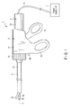
- FIG. 1 is a diagram showing an ultrasonic treatment device (ultrasonic surgical device) 1 according to the present embodiment.
- the ultrasonic treatment device 1 includes an ultrasonic transducer 2, a handle unit 3 to which the ultrasonic transducer 2 is coupled from a proximal direction side, and a treatment unit 5 coupled to the handle unit 3 from a distal direction side.
- One end of a cable 6 is connected to the ultrasonic transducer 2.
- the other end of the cable 6 is connected to a power supply unit 7.
- the handle unit 3 includes a cylindrical case 11, a fixed handle 12 formed integrally with the cylindrical case 11, and a movable handle 13 configured to open/close relative to the fixed handle 12.
- a rotational operation knob 15 is provided to the distal direction side of the cylindrical case 11.
- the rotational operation knob 15 is attached to the cylindrical case 11 rotatably around a longitudinal axis C.
- the ultrasonic transducer 2 is inserted into the handle unit 3 from the proximal direction side, and is coupled to the cylindrical case 11 of the handle unit 3.
- the treatment unit 5 includes a sheath 17 extending along the longitudinal axis C from the inside of the handle unit 3 toward the distal direction.
- the distal end of the sheath 17 is located to the distal direction side of the rotational operation knob 15. That is, the sheath 17 is provided to project from the rotational operation knob 15 toward the distal direction.
- the treatment unit 5 includes a probe 19 configured to be inserted through the sheath 17.
- the probe 19 is supported by the sheath 17 via a support member (not shown).
- a distal end of the probe 19 is located to the distal direction side of the distal end of the sheath 17. That is, the probe 19 is provided to project from the distal end of the sheath 17 toward the distal direction.
- the sheath 17 and the probe 19 are inserted into the handle unit 3. Inside the handle unit 3, the sheath 17 is coupled to the rotational operation knob 15 of the handle unit 3. Inside the handle unit 3, the sheath 17 and the probe 19 are also coupled to the ultrasonic transducer 2.
- a jaw 21 is coupled to a distal end portion of the sheath 17.
- the jaw 21 is rotatable relative to the sheath 17 around a portion coupled to the sheath 17.
- the jaw 21 rotates relative to the sheath 17, and thereby opens/closes relative to a distal end portion of the probe 19.
- a living tissue can be grasped between the distal end portion of the probe 19 and the jaw 21 by the open/close motion of the jaw 21.
- the sheath 17, the probe 19, and the jaw 21 are rotatable relative to the cylindrical case 11 around the longitudinal axis C together with the rotational operation knob 15.
- FIG. 2 is a diagram showing the configurations of the ultrasonic transducer 2, the sheath 17, and the probe 19.
- the ultrasonic transducer 2 includes a vibrator case 23, and an ultrasonic generating device (ultrasound generating device) 25 provided inside the vibrator case 23.
- the proximal end portion of the sheath 17 is fitted into the vibrator case 23 so that the vibrator case 23 is coupled to the sheath 17.
- the ultrasonic generating device 25 is coupled to the probe 19.
- FIG. 3 to FIG. 5 are diagrams showing the configuration of the ultrasonic generating device 25.
- the ultrasonic generating device 25 includes an ultrasonic vibrator (ultrasonic oscillator) 26 configured to generate ultrasonic vibrations when supplied with a current, and a horn 27 provided to the distal direction side of the ultrasonic vibrator 26. The amplitude of ultrasonic vibrations is increased by the horn 27.
- an internal thread portion 28 is formed in a distal end portion of the horn 27.
- An external thread portion 29 is formed in a proximal end portion of the probe 19. The external thread portion 29 is threaded into the internal thread portion 28, and the ultrasound generating device 25 is thereby coupled to the probe 19.
- the ultrasonic vibrations generated in the ultrasonic vibrator 26 are transmitted to the distal end of the probe 19 through (via) the horn 27 and the probe 19. That is, the ultrasonic vibrations are transmitted to the distal end from the proximal end in the probe 19 along the longitudinal axis C.
- the distal end of the probe 19 and the proximal end of the ultrasonic generating device 25 are anti-node positions of the ultrasonic vibrations.
- the ultrasonic vibrations are longitudinal vibrations in which an transmission direction coincides with a vibration direction of the ultrasonic vibrations.
- the transmission direction and vibration direction of the ultrasonic vibration are parallel to the longitudinal axis C.
- Frictional heat is generated between the distal end portion of the probe 19 and a living tissue such as a blood vessel by the ultrasonic vibrations of the probe 19 when the living tissue is grasped between the distal end portion of the probe 19 and the jaw 21.
- the living tissue is cut and coagulated between the distal end portion of the probe 19 and the jaw 21 by the generated frictional heat.
- the distal end portion of the probe 19 is a treatment portion 22 to which the ultrasonic vibrations generated by the ultrasonic generating device 25 are transmitted, and which is configured to conduct a treatment by using the transmitted ultrasonic vibrations.
- the ultrasonic generating device 25 is provided with a columnar portion 31 located to the proximal direction side of the horn 27 along the longitudinal axis C.
- the columnar portion 31 is provided integrally with the horn 27 or provided to be coupled to the proximal direction side of the horn 27.
- the ultrasonic vibrator 26 of the ultrasonic generating device 25 includes a plurality of (six in the present embodiment) ring-shaped piezoelectric elements (mounted piezoelectric elements) 33A to 33F.
- a supplied current is converted to ultrasonic vibrations by piezoelectric elements 33A to 33F.
- the same number of element mounting portions 35A to 35F as piezoelectric elements 33A to 33F are formed in the columnar portion 31.
- Element mounting portions 35A to 35F are located at positions different from one another in a transmission direction of the ultrasonic vibrations.
- Each of the piezoelectric elements 33A to 33F is mounted on a corresponding element mounting portion 35A to 35F.
- piezoelectric element 33A is mounted on the element mounting portion 35A.
- Each piezoelectric element 33A to 33F is mounted in a state that thickness directions are parallel to the transmission direction of the ultrasonic vibrations and in a state that diametrical directions are perpendicular to the transmission direction of the ultrasonic
- a first electrode 37 and a second electrode 38 are mounted on the columnar portion 31.
- the first electrode 37 includes a ring portion 41A located to the distal direction side of piezoelectric element 33A, a ring portion 41B located between piezoelectric element 33B and piezoelectric element 33C, a ring portion 41C located between piezoelectric element 33D and piezoelectric element 33E, and a ring portion 41D located to the proximal direction side of piezoelectric element 33F.
- the first electrode 37 also includes a link portion 42A which electrically connects the ring portion 41A and the ring portion 41B, a link portion 42B which electrically connects the ring portion 41B and the ring portion 41C, and a link portion 42C which electrically connects the ring portion 41C and the ring portion 41D.
- One end of an electrical signal line 43 is connected to the first electrode 37.
- the other end of electrical signal line 43 is connected to the power supply unit 7 through an inside of the cable 6.
- the second electrode 38 includes a ring portion 45A located between piezoelectric element 33A and piezoelectric element 33B, a ring portion 45B located between piezoelectric element 33C and piezoelectric element 33D, and a ring portion 45C located between piezoelectric element 33E and piezoelectric element 33F.
- the second electrode 38 also includes a link portion 46A which electrically connects the ring portion 45A and the ring portion 45B, and a link portion 46B which electrically connects the ring portion 45B and the ring portion 45C.
- One end of an electrical signal line 47 is connected to the second electrode 38.
- the other end of electrical signal line 47 is connected to the power supply unit 7 through the inside of the cable 6.
- a button portion 49 is provided to the fixed handle 12 of the handle unit 3.
- the button portion 49 is electrically connected to the power supply unit 7 via, for example, an electrical signal line (not shown).
- an electrical signal is input to the power supply unit 7.
- a current having a predetermined current value is supplied to piezoelectric elements 33A to 33F from the power supply unit 7 via electrical signal lines 43 and 47, the first electrode 37, and the second electrode 38.
- the supplied current is converted to ultrasonic vibrations in each of piezoelectric elements 33A to 33F. Thereby, ultrasonic vibrations are generated in the ultrasonic vibrator 26.
- a proximal end of the ultrasonic generating device 25 (a proximal end of the columnar portion 31) and a distal end of the ultrasonic generating device 25 (a distal end of the horn 27) are the anti-node positions (loop positions) of the ultrasonic vibrations.
- the dimension of the ultrasonic generating device 25 along the longitudinal axis C (in the transmission direction of the ultrasonic vibrations) is equal to half the wavelength of the ultrasonic vibrations.
- element mounting portion 35A is at the shortest distance from (closest to) the node position of the ultrasonic vibrations in the transmission direction of the ultrasonic vibrations.
- element mounting portion 35F is at the greatest distance from (farthest from) the node position of the ultrasonic vibrations in the transmission direction of the ultrasonic vibrations.
- insulating rings 51A and 51B are mounted on the columnar portion 31.
- the insulating ring 51A is located to the distal direction side of the ring portion 41A of the first electrode 37.
- the insulating ring 51B is located to the proximal direction side of the ring portion 41D of the first electrode 37.
- the insulating ring 51A is provided so that the current supplied from the power supply unit 7 is not transmitted toward the distal direction side from the insulating ring 51A.
- the insulating ring 51B is provided so that the current supplied from the power supply unit 7 is not transmitted toward the proximal direction side from the insulating ring 51B.
- a back-mass 53 is also mounted on the columnar portion 31.
- the back-mass 53 is located to the proximal direction side of the insulating ring 51B.
- Piezoelectric elements 33A to 33F, the first electrode 37, the second electrode 38, and the insulating rings 51A and 51B are pressed toward the distal direction by the back-mass 53.
- piezoelectric elements 33A to 33F, the first electrode 37, the second electrode 38, and the insulating rings 51A and 51B are held between the horn 27 and the back-mass 53. Therefore, piezoelectric elements 33A to 33F, the first electrode 37, the second electrode 38, and the insulating rings 51A and 51B which are firmly fixed between the horn 27 and the back-mass 53 are mounted on the columnar portion 31.
- FIG. 6 is a diagram showing an ultrasonic adjusting device (ultrasound adjusting device) 60 used in the manufacture of the ultrasonic generating device 25.
- the amplitude of ultrasonic vibrations generated by the ultrasonic generating device 25 is adjusted by the use of the ultrasonic adjusting device 60.
- the ultrasonic adjusting device 60 includes the above-described piezoelectric elements 33A to 33F, and element mounting portions 35A to 35F in each of which a corresponding piezoelectric element 33A to 33F is mounted.
- the ultrasonic adjusting device 60 also includes a plurality of (50 in the present embodiment) existing piezoelectric elements P1 to P50 which are piezoelectric elements that exist during manufacture.
- Each of the piezoelectric elements (mounted piezoelectric elements) 33A to 33F to be mounted on the corresponding element mounting portion 35A to 35F is selected from existing piezoelectric elements P1 to P50.
- Each of existing piezoelectric elements P1 to P50 has a first electromechanical coupling factor Kt in the thickness directions, and a second electromechanical coupling factor Kp in the diametrical directions.
- the first electromechanical coupling factor Kt is a factor indicating the relation between electrical energy and vibrational energy in the thickness directions when a current is supplied to each of existing piezoelectric elements P1 to P50.
- the second electromechanical coupling factor Kp is a factor indicating the relation between electrical energy and vibrational energy in the diametrical directions when a current is supplied to each of existing piezoelectric elements P1 to P50.
- Each of the piezoelectric elements 33A to 33F selected from existing piezoelectric elements P1 to P50 are mounted so that the thickness directions are parallel to the transmission direction of the ultrasonic vibrations and so that the diametrical directions are perpendicular to the transmission direction of the ultrasonic vibrations. Accordingly, the proportionality constant between the current value of the supplied current and the amplitude of the ultrasonic vibrations varies according to a value of the first electromechanical coupling factor Kt and a value of the second electromechanical coupling factor Kp of each of piezoelectric elements 33A to 33F.
- the amplitude of the ultrasonic vibrations when a predetermined current is supplied varies in accordance with the value of the first electromechanical coupling factor Kt and the value of the second electromechanical coupling factor Kp of each of piezoelectric elements 33A to 33F.
- the ultrasonic adjusting device 60 includes a calculating unit 61 such as a computer.
- the calculating unit 61 includes an input section 62, a performance value calculating section 63, and a recording section 65.
- FIG. 7 is a flowchart showing the manufacturing method of the ultrasonic generating device 25. As shown in FIG. 7 , when the ultrasonic generating device 25 is manufactured, the performance value of each of existing piezoelectric elements P1 to P50 is calculated by the performance value calculating section 63 (step S101). At the same time, a performance value based on the first electromechanical coupling factor Kt and the second electromechanical coupling factor Kp is calculated for each of existing piezoelectric elements P1 to P50.
- a performance value Kt/Kp is calculated on the basis of the first electromechanical coupling factor Kt and the second electromechanical coupling factor Kp for each of existing piezoelectric elements P1 to P50.
- or KtxKp may be calculated for each of existing piezoelectric elements P1 to P50.
- the first electromechanical coupling factor Kt in the thickness directions and the second electromechanical coupling factor Kp in the diametrical directions vary by each of the existing piezoelectric elements P1 to P50.
- the performance value Kt/Kp varies by each of the existing piezoelectric elements P1 to P50.
- the first electromechanical coupling factor Kt and the second electromechanical coupling factor Kp of each of existing piezoelectric elements P1 to P50 are input by the input section 62.
- the first electromechanical coupling factor Kt and the second electromechanical coupling factor Kp of each of existing piezoelectric elements P1 to P50 may be recorded in the recording section 65.
- the calculating unit 61 includes a piezoelectric element classification section 67.
- existing piezoelectric elements P1 to P50 are classified according to the performance value Kt/Kp by the piezoelectric element classification section 67 (step S102).
- the existing piezoelectric elements for example, P3 and P33
- having a performance value Kt/Kp that is 0.7875 or more and below 0.7925 are classified into a type having a performance value Kt/Kp of 0.79.
- the existing piezoelectric elements (for example, P10 and P41) having a performance value Kt/Kp that is 0.7925 or more and below 0.7975 are classified into a type having a performance value Kt/Kp of 0.795. In this way, existing piezoelectric elements P1 to P50 are classified into several types according to the performance value Kt/Kp.
- the number of the existing piezoelectric elements (P1 to P50) belonging to each of the types is recorded in the recording section 65. For example, when the performance value Kt/Kp of existing piezoelectric elements P3 and P33 is 0.7875 or more and below 0.7925, the number of the existing piezoelectric elements (P1 to P50) belonging to the type having a performance value Kt/Kp of 0.79 is two.
- the calculating unit 61 includes a target condition setting section (desired condition setting section) 68.
- a target condition in which ultrasonic vibrations having target amplitude (desired amplitude) are generated when a current having a predetermined value is supplied, is set by the target condition setting section 68 (step S103).
- FIG. 8 is a schematic diagram showing element mounting portions 35A to 35F in the target condition, a first temporary condition, and a second temporary condition (details of the target condition, the first temporary condition, and the second temporary condition will be described later).
- a corresponding reference piezoelectric element 81A to 81F having a performance value Kt/Kp equal to a reference value is mounted on each of the element mounting portions 35A to 35F in the target condition.
- the performance value Kt/Kp of each of the reference piezoelectric elements 81A to 81F is a reference value of 0.8.
- the corresponding reference piezoelectric element 81A to 81F having the performance value Kt/Kp equal to the reference value of 0.8 is mounted on each of the element mounting portions 35A to 35F.
- the performance value Kt/Kp (reference value) of corresponding reference piezoelectric element 81A to 81F mounted on each of the element mounting portions 35A to 35F in the target condition is recorded in the recording section 65.
- the performance values Kt/Kp (reference value) of all reference piezoelectric elements 81A to 81F are 0.8 in the present embodiment, but is not limited thereto.
- the target amplitude of ultrasonic vibrations to be generated by the ultrasonic generating device 25 varies, for example, according to the kind of ultrasonic treatment device 1 or its used condition.
- the performance value Kt/Kp (reference value) of each of the reference piezoelectric elements 81A to 81C may be 0.7
- the performance value Kt/Kp (reference value) of each of the reference piezoelectric elements 81D to 81F may be 0.8.
- the reference value of each of reference piezoelectric elements 81A to 81F varies according to the predetermined current supplied from the power supply unit 7. That is, in the present embodiment, a target condition to be set varies in accordance with the performance of the selected power supply unit 7.
- the piezoelectric element (mounted piezoelectric elements) 33A to 33F having the performance value Kt/Kp equal to the reference value (0.8) is not necessarily mounted on each of the element mounting portions 35A to 35F due to the number of the existing piezoelectric elements (P1 to P50) belonging to each of the types.
- the piezoelectric element (33A and 33B) having the performance value Kt/Kp different from the reference value (0.8) is mounted on each of at least one element mounting portion (for example, 35A and 35B).
- the amplitude of the ultrasonic vibrations generated by the ultrasonic generating device 25 is different from the target amplitude.
- the calculating unit 61 includes a temporary influence value calculating section 69. As shown in FIG. 7 , a temporary influence value is calculated by the temporary influence value calculating section 69 for each of temporary conditions (step S104).
- the first temporary condition and the second temporary condition are shown in FIG. 8 as examples of temporary conditions.
- a temporary piezoelectric element 81' A having the performance value Kt/Kp different from the reference value (0.8) is mounted on only element mounting portion 35A instead of reference piezoelectric element 81A as compared with the target condition (desired condition).
- the performance value Kt/Kp of the temporary piezoelectric element 81' A is 0.79.
- the reference piezoelectric element 81B to 81F having the performance value Kt/Kp equal to the reference value (0.8) is mounted on each of the element mounting portions 35B to 35F other than element mounting portion 35A.
- a temporary piezoelectric element 81' / C having the performance value Kt/Kp different from the reference value (0.8) is mounted on only element mounting portion 35C instead of reference piezoelectric element 81C as compared with the target condition.
- the performance value Kt/Kp of the temporary piezoelectric element 81' C is 0.81.
- the reference piezoelectric element 81A, 81B, and 81D to 81F having the performance value Kt/Kp equal to the reference value (0.8) is mounted on each of the element mounting portions 35A, 35B, and 35D to 35F other than element mounting portion 35C.
- a temporary piezoelectric element (for example, 81' A or 81' C) having the performance value Kt/Kp different from the reference value (0.8) is mounted on only one element mounting portion (for example, 35A or 35C) instead of the reference piezoelectric element (81A or 81C) as compared with the target condition. Therefore, in each temporary condition, ultrasonic vibrations having temporary amplitude different from the target amplitude are generated by the supply of the current having the predetermined current value.
- the temporary conditions are set for each of element mounting portions 35A to 35F on which the temporary piezoelectric element is mounted and for each performance value Kt/Kp of the temporary piezoelectric element.
- the temporary influence value calculating section 69 is configured to calculate a temporary influence value for each temporary condition (step S104).
- a temporary influence value is calculated on the basis of a deviation of the temporary amplitude of the ultrasonic vibrations generated by the supply of the current having the predetermined current value from (with respect to) the target amplitude in the target condition.
- the temporary influence value E1 (%) in the first temporary condition is as follow.
- E ⁇ 1 A ⁇ 1 - A ⁇ 0 A ⁇ 0 ⁇ 100
- A1 is the temporary amplitude of the ultrasonic vibrations generated in, for example, the first temporary condition
- A0 is the target amplitude in the target condition.
- the temporary influence value Ek in each of the temporary conditions other than the first temporary condition is calculated by the substitution of Ak for A1 in Equation (1).
- FIG. 9 is a diagram showing a table in which the temporary influence value in each of the temporary conditions is arranged.
- the temporary piezoelectric element 81' A having a performance value Kt/Kp of 0.79 is mounted on only element mounting portion 35A instead of reference piezoelectric element 81A as compared with the target condition. Therefore, as shown in FIG. 9 , the temporary influence value in the first temporary condition is -0.514(%).
- the temporary piezoelectric element 81' C having a performance value Kt/Kp of 0.81 is mounted on only element mounting portion 35C instead of reference piezoelectric element 81C as compared with the target condition. Therefore, as shown in FIG. 9 , the temporary influence value in the second temporary condition is 0.447(%).
- the change of the temporary influence value with respect to the change of the performance value Kt/Kp of the temporary piezoelectric element from the reference value is greater when the temporary piezoelectric element is mounted on element mounting portion 35A rather than on element mounting portion 35C.
- the temporary influence value is -1.028(%) in the temporary condition in which the temporary piezoelectric element having a performance value Kt/Kp of 0.78 is mounted on element mounting portion 35A, whereas the temporary influence value is -0.894(%) in the temporary condition in which the temporary piezoelectric element having a performance value Kt/Kp of 0.78 is mounted on element mounting portion 35C.
- element mounting portion 35A is less distant from the node position of the ultrasonic vibrations in the transmission direction of the ultrasonic vibrations than element mounting portion 35C. That is, the change of the temporary influence value is greater as the distance from the node position of the ultrasonic vibrations to each of element mounting portions 35A to 35F in the transmission direction of the ultrasonic vibrations is shorter.
- the change of the performance values of piezoelectric elements 33A to 33F to be mounted has a greater influence on the amplitude of the ultrasonic vibrations as the distance from the node position of the ultrasonic vibrations to each of element mounting portions 35A to 35F in the transmission direction of the ultrasonic vibrations is shorter.
- the calculating unit 61 includes a piezoelectric element selection section 71.
- the piezoelectric element selection section 71 is configured to each of select piezoelectric elements (mounted piezoelectric elements) 33A to 33F to be mounted on the corresponding element mounting portion 35A to 35F from existing piezoelectric elements P1 to P50 (step S105).
- the temporary influence value in the temporary condition in which the temporary piezoelectric element having the same performance value Kt/Kp as the corresponding piezoelectric element 33A to 33F to be actually mounted, is used as an actual influence value.
- a temporary influence value of -0.514% in the first temporary condition is the actual influence value of the element mounting portion 35A.
- the piezoelectric element selection section 71 selects the corresponding piezoelectric element 33A to 33F to be mounted on each of the element mounting portions 35A to 35F so that the sum of the actual influence values (real influence values) of all element mounting portions 35A to 35F is within a predetermined range with respect to (for) the target amplitude.
- the corresponding piezoelectric element 33A to 33F to be mounted on each of the element mounting portion 35A to 35F is selected so that the sum of the actual influence values of all element mounting portions 35A to 35F is within a predetermined range from -2% to +2%. If the sum of the actual influence values of all element mounting portions 35A to 35F is within the range from -2% to +2%, there will be no great difference between the actual amplitude (real amplitude) of the ultrasonic vibrations and the target amplitude when a current having a predetermined value is supplied. As a result, the amplitude of ultrasonic vibrations to be generated is stable in each of the manufactured ultrasonic generating devices 25. This effectively prevents the variation of treatment performance among the ultrasonic treatment devices 1 each of which includes corresponding ultrasonic generating devices 25.
- the piezoelectric element selection section 71 selects piezoelectric elements 33A and 33B having a performance value Kt/Kp of 0.84, piezoelectric element 33C having a performance value Kt/Kp of 0.8, and piezoelectric elements 33D, 33E, and 33F having a performance value Kt/Kp of 0.765.
- the actual influence value of element mounting portion 35A is 2.056(%)
- the actual influence value of element mounting portion 35B is 1.922(%)
- the actual influence value of element mounting portion 35C is 0(%)
- the actual influence value of element mounting portion 35D is -1.448(%)
- the actual influence value of element mounting portion 35E is -1.331(%)
- the actual influence value of element mounting portion 35F is -1.214(%).
- the target condition to be set varies according to the performance of the selected power supply unit 7.
- the actual influence value of each of the element mounting portions 35A to 35F is then calculated on the basis of the set target condition, and each of piezoelectric elements 33A to 33F is selected on the basis of the sum of the actual influence values of all element mounting portions 35A to 35F. Therefore, each of piezoelectric elements (mounted piezoelectric elements) 33A to 33F is selected in accordance with the performance of the selected power supply unit 7, for example, the predetermined current value of the current to be supplied to the ultrasonic generating device 25, and the performance of the ultrasonic generating device 25 is set.
- the performance of the power supply unit 7 and the performance of the treatment portion 22 are not set in accordance with the performance of the ultrasonic generating device 25.
- the piezoelectric element selection section 71 selects each of piezoelectric elements (mounted piezoelectric elements) 33A to 33F preferential from a type including more existing piezoelectric elements among existing piezoelectric elements P1 to P50 classified into types by the piezoelectric element classification section 67 based on to the performance value Kt/Kp. For example, there are a plurality of combinations of piezoelectric elements 33A to 33F such that the sum of the actual influence values of all element mounting portions 35A to 35F is within a predetermined range with respect to the target amplitude.
- the existing number of existing piezoelectric elements in the type (for example, P20 and P29) having a performance value Kt/Kp of 0.76 is a greater than other types among existing piezoelectric elements P1 to P50.
- a combination in which the number of existing piezoelectric elements, which belong the type having a performance value Kt/Kp of 0.76, is greater in the piezoelectric elements 33A to 33F to be mounted is selected from a plurality of combinations.
- the piezoelectric elements are selected as each of piezoelectric elements 33A to 33F preferential from a type including more existing piezoelectric elements among existing piezoelectric elements P1 to P50 classified into types according to the performance value Kt/Kp on the condition that the sum of the actual influence values of all element mounting portions 35A to 35F is within a predetermined range with respect to the target amplitude. Consequently, piezoelectric elements (mounted piezoelectric elements) 33A to 33F are efficiently selected from existing piezoelectric elements P1 to P50 in which the existing number of existing piezoelectric elements in each of the types is different from other types.
- the ultrasonic generating device 25 when the ultrasonic generating device 25 is manufactured, components such as the columnar portion 31 and the back-mass 53 are cleaned in parallel with steps S101 to S105 (step S106). Cleaning of the components prevents the performance deterioration of the ultrasonic generating device 25 and the ultrasonic treatment device 1 caused by, for example, dirt.
- the first electrode 37 and the second electrode 38 are formed by bending (step S107). As a modification, it is possible to provide no link portions 42A to 42C in the first electrode 37, and connect a corresponding electrical signal line (not shown) to each of the ring portions 41A to 41D. In this case, the first electrode 37 is not formed by bending. Similarly, it is possible to provide no link portions 46A and 46B in the second electrode 38, and connect a corresponding electrical signal line (not shown) to each of the ring portions 45A to 45C. In this case, the second electrode 38 is not formed by bending.
- step S108 An adhesive material is then applied (coated) between the components (step S108).
- Components such as piezoelectric elements 33A to 33F selected in step S105 are then mounted on the columnar portion 31 (step S109). At this time, each of the piezoelectric elements 33A to 33F is mounted on the corresponding element mounting portion 35A to 35F. Each of the piezoelectric elements 33A to 33F is mounted so that the thickness directions are parallel to the transmission direction of the ultrasonic vibrations and so that the diametrical directions are perpendicular to the transmission direction of the ultrasonic vibrations.
- the back-mass 53 is then mounted (step S110). Components such as piezoelectric elements 33A to 33F are pressed toward the distal direction by the back-mass 53.
- step S108 The adhesive material applied in step S108 is then cured (step S111), and parts between the components are firmly bonded. Bonding may be only performed between the horn 27 and the back-mass 53 to only prevent unfastening after production.
- the ultrasonic generating device 25 is manufactured as described above in steps S101 to S111.
- the power supply unit 7 is electrically connected to piezoelectric elements 33A to 33F via, for example, electrical signal lines 43 and 47.
- the probe 19 is then coupled to the horn 27 of the ultrasonic generating device 25.
- the treatment portion 22, to which the ultrasonic vibrations generated by the ultrasonic generating device 25 are transmitted and which is configured to conduct a treatment by using the transmitted ultrasonic vibrations, is formed.
- the ultrasonic generating device 25 having the configuration described above and the manufacturing method of the ultrasonic generating device 25 provide the following advantageous effects. That is, when the ultrasonic generating device 25 is manufactured, the actual influence value of each of element mounting portions 35A to 35F is found by the use of temporary influence value in the corresponding temporary condition.
- the piezoelectric element selection section 71 selects each of piezoelectric elements 33A to 33F to be mounted on the corresponding element mounting portion 35A to 35F so that the sum of the actual influence values of all element mounting portions 35A to 35F is within a predetermined range (for example, -2% to +2%) with respect to the target amplitude.
- the amplitude of ultrasonic vibrations to be generated is stable in each of the manufactured ultrasonic generating devices 25. That is, the variation of the amplitude of the ultrasonic vibrations generated in each ultrasonic generating device 25 can be reduced. This effectively prevents the difference (variation) of treatment performance among each of the ultrasonic treatment device 1 which use the corresponding ultrasonic generating devices 25.
- the target condition which is set when the ultrasound generating device 25 is manufactured, varies according to the performance of the selected power supply unit 7.
- the actual influence value of each of the element mounting portions 35A to 35F is then calculated on the basis of the set target condition, and each of piezoelectric elements 33A to 33F is selected on the basis of the sum of the actual influence values of all element mounting portions 35A to 35F. Therefore, each of piezoelectric elements (mounted piezoelectric elements) 33A to 33F is selected in accordance with the performance of the power supply unit 7, for example, a predetermined current value of the current to be supplied to the ultrasonic generating device 25, and the performance of the ultrasonic generating device 25 is set.
- the performance of the power supply unit 7 and the performance of the treatment portion 22 are not set in accordance with the performance of the ultrasonic generating device 25.
- the power supply unit 7 it is not necessary to provide the power supply unit 7 with a control system which is configured to adjust the current value of the current to be supplied to the ultrasonic generating device 25 in accordance with the performance of the ultrasonic generating device 25.
- a change of the temporary influence value with respect to the change of the performance value Kt/Kp from the reference value (0.8) is calculated greater as the distance from the node position of the ultrasonic vibrations to each of element mounting portions 35A to 35F in the transmission direction of the ultrasonic vibrations is shorter.
- the change of the performance value of each of piezoelectric elements 33A to 33F to be mounted has a greater influence on the amplitude of the ultrasonic vibrations as the distance from the node position of the ultrasonic vibrations to each of element mounting portions 35A to 35F in the transmission direction of the ultrasonic vibrations is shorter. Therefore, the accuracy of a temporary influence value to be calculated can be enhanced.
- the piezoelectric elements 33A to 33F are selected preferential from a type including more existing piezoelectric elements among existing piezoelectric elements P1 to P50 classified into types according to the performance value Kt/Kp, as long as the sum of the actual influence values of all element mounting portions 35A to 35F is within the predetermined range with respect to the target amplitude. Consequently, each of piezoelectric elements (mounted piezoelectric elements) 33A to 33F can be efficiently selected from existing piezoelectric elements P1 to P50 in which the existing number in each of types is different (varies) from other types.
- the proximal end of the ultrasonic generating device 25 (the proximal end of the columnar portion 31) and the distal end of the ultrasonic generating device 25 (the distal end of the horn 27) are the anti-node positions of the ultrasonic vibrations in the first embodiment
- the distal end of the ultrasonic generating device 25 (the distal end of the horn 27) does not have to be the anti-node position of the ultrasonic vibrations.
- the proximal end of the ultrasonic generating device 25 (the proximal end of the columnar portion 31) and the distal end of the probe 19 are the anti-node positions of the ultrasonic vibrations.
- the dimension of the ultrasonic generating device 25 in the transmission direction of the ultrasonic vibrations is equal to half the wavelength of the ultrasonic vibrations in the first embodiment, this is not a limitation.
- the position of each of element mounting portions 35A to 35F in the transmission direction of the ultrasonic vibrations is not limited to the position in the first embodiment.
- the dimension of the ultrasonic generating device 25 in the transmission direction of the ultrasonic vibrations may be equal to one wavelength of the ultrasonic vibrations.
- element mounting portions 82A to 82F are provided instead of element mounting portions 35A to 35F.
- a corresponding piezoelectric element 33A to 33F is mounted on each of the element mounting portions 82A to 82F.
- a columnar portion 83 having a larger diameter than the columnar portion 31 is formed between element mounting portion 82A and the horn 27.
- Each of piezoelectric elements 33A to 33F is mounted to be fixed between the back-mass 53 and the columnar portion 83.
- the temporary influence value calculating section 69 is configured to calculate each temporary influence value so that the change of the temporary influence value with respect to the change of the performance value Kt/Kp from the reference value is greater as the distance from the node position of the ultrasonic vibrations to each of element mounting portions 82A to 82F in the transmission direction of the ultrasonic vibrations is shorter.
- the distance from the node position of the ultrasonic vibrations to each of element mounting portions 82B and 82E in the transmission direction of the ultrasonic vibrations substantially coincides with the distance from the node position of the ultrasonic vibrations to element mounting portion 35A in the transmission direction of the ultrasonic vibrations in the first embodiment.
- the change of the temporary influence value in each of element mounting portions 82B and 82E with respect to the change of the performance value Kt/Kp from the reference value show substantially the same characteristics as the change of the temporary influence value in element mounting portion 35A in response to the change of the performance value Kt/Kp from the reference value (see FIG. 9 ).
- the dimension of the ultrasonic generating device 25 in the transmission direction of the ultrasonic vibrations may be equal to one wavelength of the ultrasonic vibrations, and element mounting portions 85A to 85F may be provided instead of element mounting portions 35A to 35F.
- a cylindrical member 86 is provided (mounted) between element mounting portion 85B and element mounting portion 85C.
- Each of piezoelectric elements 33A to 33F and the cylindrical member 86 are mounted to be fixed between the back-mass 53 and the horn 27.
- the temporary influence value calculating section 69 is configured to calculate each temporary influence value so that the change of the temporary influence value with respect to the change of the performance value Kt/Kp from the reference value is greater as the distance from the node position of the ultrasonic vibrations to each of element mounting portions 85A to 85F in the transmission direction of the ultrasonic vibrations is shorter.
- the distance from the node position of the ultrasonic vibrations to each of element mounting portions 85A, 85C, and 85F in the transmission direction of the ultrasonic vibrations substantially coincide with the distance from the node position of the ultrasonic vibrations to element mounting portion 35A in the transmission direction of the ultrasonic vibrations in the first embodiment.
- the change of the temporary influence value in each of element mounting portions 85A, 85C, and 85F with respect to the change of the performance value Kt/Kp from the reference value show substantially the same characteristics as the change of the temporary influence value in element mounting portion 35A with respect to the change of the performance value Kt/Kp from the reference value (see FIG. 9 ).
- the dimension of the ultrasonic generating device 25 in the transmission direction of the ultrasonic vibrations may be equal to 1.5 wavelengths of the ultrasonic vibrations.
- eight element mounting portions 91A to 91H are provided instead of element mounting portions 35A to 35F.
- a corresponding piezoelectric element (mounted piezoelectric element) 33A to 33H is mounted on each of the element mounting portions 91A to 91H.
- a columnar portion 92 having a larger diameter than the columnar portion 31 is formed between element mounting portion 91A and the horn 27.
- a cylindrical member 93 is mounted between element mounting portion 91D and element mounting portion 91E.
- Each of piezoelectric elements 33A to 33H and the cylindrical member 93 are mounted to be fixed between the back-mass 53 and the columnar portion 92.
- the temporary influence value calculating section 69 is configured to calculate each temporary influence value so that the change of the temporary influence value with respect to the change of the performance value Kt/Kp from the reference value is greater as the distance from the node position of the ultrasonic vibrations to each of element mounting portions 91A to 91H in the transmission direction of the ultrasonic vibrations is shorter.
- the distance from the node position of the ultrasonic vibrations to each of element mounting portions 91A, 91D, 91E, and 91H in the transmission direction of the ultrasonic vibrations substantially coincides with the distance from the node position of the ultrasonic vibrations to element mounting portion 35A in the transmission direction of the ultrasonic vibrations in the first embodiment.
- the change of the temporary influence value in each of element mounting portions 91A, 91D, 91E, and 91H with respect to the change of the performance value Kt/Kp from the reference value show substantially the same characteristics as the change of the temporary influence value in element mounting portion 35A with respect to the change of the performance value Kt/Kp from the reference value (see FIG. 9 ).
- the ultrasonic generating device 25 is provided inside the vibrator case 23 in the ultrasonic treatment device 1 according to the first embodiment, this is not a limitation.
- the ultrasonic generating device 25 is provided inside the cylindrical case 11 of the handle unit 3.
- One end of the cable 6 is connected to the cylindrical case 11.
- Electrical signal lines 43 and 47 each of which has one end connected to the ultrasonic generating device 25, and the other end connected to the power supply unit 7 through an inside of the cylindrical case 11 and an inside of the cable 6.
- An ultrasonic adjusting device comprising:
- the ultrasonic adjusting device is configured to calculate the temporary influence value so that a change of the temporary influence value with respect to a change of the performance value from the reference value is greater as a distance from a node position of the ultrasonic vibrations to each of the element mounting portions in the transmission direction of the ultrasonic vibrations is shorter.
- the ultrasonic adjusting device according to additional note 1, wherein the piezoelectric element selection section is configured to select the mounted piezoelectric elements preferential from a type including more existing piezoelectric elements among the existing piezoelectric elements classified into types according to the performance value on the condition that the sum of the actual influence values of all the element mounting portions is within the predetermined range with respect to the target amplitude.
Landscapes
- Engineering & Computer Science (AREA)
- Health & Medical Sciences (AREA)
- Manufacturing & Machinery (AREA)
- Life Sciences & Earth Sciences (AREA)
- General Health & Medical Sciences (AREA)
- Veterinary Medicine (AREA)
- Nuclear Medicine, Radiotherapy & Molecular Imaging (AREA)
- Animal Behavior & Ethology (AREA)
- Biomedical Technology (AREA)
- Public Health (AREA)
- Mechanical Engineering (AREA)
- Radiology & Medical Imaging (AREA)
- Surgical Instruments (AREA)
- Apparatuses For Generation Of Mechanical Vibrations (AREA)
- Surgery (AREA)
- Dentistry (AREA)
- Heart & Thoracic Surgery (AREA)
- Medical Informatics (AREA)
- Molecular Biology (AREA)
Abstract
Description
- The present invention relates to an ultrasonic generating device configured to generate ultrasonic vibrations when supplied with a current, and an ultrasonic treatment device including the ultrasonic generating device. The present invention also relates to a manufacturing method of the ultrasonic generating device and a manufacturing method of the ultrasonic treatment device.
- An ultrasonic surgery device (ultrasonic treatment device) disclosed in Patent Literature includes an ultrasonic generating device (ultrasonic vibrator unit) including an ultrasonic vibrator which formed from a plurality of piezoelectric elements, and a probe which is connected to the ultrasonic vibrator unit and which is configured to transmit ultrasonic vibrations generated in the ultrasonic vibrator (ultrasonic oscillator), the probe being configured to treat a living tissue by a treatment portion formed at a distal end portion thereof. When a predetermined constant current is supplied to the ultrasonic vibrator from a power supply unit, this ultrasonic surgery device is configured to ultrasonically vibrate the probe (treatment portion) with constant amplitude. That is, the ultrasonic vibrator is driven by constant current control, and the constant amplitude of the ultrasonic vibrations in the probe (treatment portion) is maintained.
- Patent Literature 1: Jpn. Pat. Appln. KOKAI Publication No.
2010-000336 - In the ultrasonic generating device shown in
Patent Literature 1, the amplitude of the generated ultrasonic vibrations is proportional to a current value of the supplied current. The proportionality constant between the current value and the amplitude of the ultrasonic vibrations changes with at least a first electromechanical coupling factor of each piezoelectric element in thickness directions and a second electromechanical coupling factor of each piezoelectric element in diametrical directions. Here, when each piezoelectric element is manufactured, it is not possible to set the first electromechanical coupling factor in the thickness directions and the second electromechanical coupling factor in the diametrical directions to desired values. Therefore, the first electromechanical coupling factor in the thickness directions and the second electromechanical coupling factor in the diametrical directions vary by each of the manufactured piezoelectric elements. - Accordingly, the proportionality constant between the current value and the amplitude of the ultrasonic vibrations varies according to the ultrasonic generating devices (ultrasound generating devices). Therefore, when a current having a predetermined current value is supplied from the power supply unit, the amplitude of ultrasonic vibrations to be generated varies according to the ultrasonic generating devices. In an ultrasonic treatment device such as a medical apparatus including a treatment portion configured to conduct an ultrasonic treatment (ultrasonic surgery) by using ultrasonic vibrations generated by the ultrasonic generating device, the amplitude of the ultrasonic vibrations has a great influence on the treatment performance. Thus, the variation of the amplitude of the ultrasonic vibrations to be generated according to the ultrasonic generating devices leads to the variation of the treatment performance of the ultrasonic treatment device according to the ultrasound generating device to be used.
- The present invention has been made in view of the problems described above. An object of the present invention is to provide an ultrasonic generating device and a manufacturing method of the ultrasonic generating device configured to stabilize the amplitude of ultrasonic vibrations to be generated. Another object of the present invention is to provide an ultrasonic treatment device which includes the ultrasonic generating device and a manufacturing method of the ultrasonic treatment device.
- To solve above mentioned problems, according to one aspect of the invention, a manufacturing method of an ultrasonic generating device, the manufacturing method includes that: calculating performance value based on a first electromechanical coupling factor in thickness directions and a second electromechanical coupling factor in diametrical directions for each of existing piezoelectric elements; setting a target condition where ultrasonic vibrations having target amplitude are generated when a corresponding reference piezoelectric element having the performance value equal to a reference value is mounted on each of a plurality of element mounting portions located at positions different from one another in a transmission direction of the ultrasonic vibrations and when a current having a predetermined current value is supplied; calculating, for each of temporary conditions, a temporary influence value on the basis of a deviation of temporary amplitude of the ultrasonic vibrations, generated by the supply of the current having the predetermined current value, from the target amplitude in the target condition, a temporary piezoelectric element having the performance value different from the reference value being mounted on only one element mounting portion instead of the reference piezoelectric element in each of the temporary conditions as compared with the target condition, the temporary conditions being set for each of the element mounting portions on which the temporary piezoelectric element is mounted and for each of the performance values of the temporary piezoelectric elements; selecting the corresponding mounted piezoelectric element to be mounted on each of the element mounting portions from the existing piezoelectric elements so that the sum of actual influence values of all the element mounting portions is within a predetermined range with respect to the target amplitude, when the temporary influence value in the corresponding temporary condition, in which the temporary piezoelectric element having the same performance value as the mounted piezoelectric element to be actually mounted is mounted, is used as the actual influence value in each of the element mounting portions; and mounting the selected corresponding mounted piezoelectric elements on each of the element mounting portions so that the thickness directions thereof are parallel to the transmission direction of the ultrasonic vibrations and so that the diametrical directions thereof are perpendicular to the transmission direction of the ultrasonic vibrations.
- Further, according to one another aspect of the invention, an ultrasonic generating device includes that: a plurality of element mounting portions located at positions different from one another in a transmission direction of ultrasonic vibrations; and a plurality of mounted piezoelectric elements each of which has a performance value based on a first electromechanical coupling factor in the thickness directions and a second electromechanical coupling factor in the diametrical directions, each of the mounted piezoelectric elements being mounted on the corresponding element mounting portion so that the thickness directions are parallel to the transmission direction of the ultrasonic vibrations and so that the diametrical directions are perpendicular to the transmission direction of the ultrasonic vibrations, wherein each of the mounted piezoelectric elements is selected from existing piezoelectric elements so that a sum of actual influence values of all the element mounting portions is within a predetermined range with respect to the target amplitude, in a case of being set a target condition where the ultrasonic vibrations having the target amplitude are generated when a corresponding reference piezoelectric element having the performance value equal to a reference value is mounted on each of the element mounting portions and when a current having a predetermined current value is supplied, in a case of calculating, for each of temporary conditions, a temporary influence value on the basis of a deviation of temporary amplitude of the ultrasonic vibrations, generated by the supply of the current having the predetermined current value, from the target amplitude in the target condition, a temporary piezoelectric element having the performance value different from the reference value is mounted on only one element mounting portion instead of the reference piezoelectric element in each of the temporary conditions as compared with the target condition, the temporary conditions being set for each of the element mounting portions on which the temporary piezoelectric element is mounted and for each of the performance values of the temporary piezoelectric elements, and in a case of using the temporary influence value in the corresponding temporary condition, in which the temporary piezoelectric element having the same performance value as the mounted piezoelectric element is mounted, as the actual influence value in each of the element mounting portions.
- According to the present invention, a an ultrasonic generating device and a manufacturing method of the ultrasonic generating device, configured to stabilize the amplitude of ultrasonic vibrations to be generated regardless of an initial setting of the power supply unit to be combine and without the complicated configuration of the power supply unit, can be provided. An ultrasonic treatment device which includes the ultrasonic generating device and a manufacturing method of the ultrasonic treatment device can be provided.
-
-
FIG. 1 is a schematic diagram showing an ultrasonic treatment device according to a first embodiment of the present invention; -
FIG. 2 is a schematic sectional view showing the configurations of an ultrasonic transducer, a sheath, and a probe of the ultrasonic treatment device according to the first embodiment; -
FIG. 3 is a schematic perspective view showing an ultrasonic generating device according to the first embodiment; -
FIG. 4 is a schematic perspective view showing the ultrasonic generating device according to the first embodiment which is disassembled into components; -
FIG. 5 is a schematic diagram showing the ultrasonic generating device according to the first embodiment; -
FIG. 6 is a schematic diagram showing an ultrasonic adjusting device used in the manufacture of the ultrasonic generating device according to the first embodiment; -
FIG. 7 is a flowchart showing a manufacturing method of the ultrasonic generating device according to the first embodiment; -
FIG. 8 is a schematic diagram showing a target condition, a first temporary condition, and a second temporary condition of each element mounting portion of the ultrasonic generating device according to the first embodiment; -
FIG. 9 is a schematic diagram showing temporary influence value in each of the temporary conditions of the ultrasonic generating device according to the first embodiment; -
FIG. 10 is a schematic diagram showing an ultrasonic generating device according to a first modification of the first embodiment; -
FIG. 11 is a schematic diagram showing an ultrasonic generating device according to a second modification of the first embodiment; -
FIG. 12 is a schematic diagram showing an ultrasonic generating device according to a third modification of the first embodiment; -
FIG. 13 is a schematic diagram showing an ultrasonic generating device according to a fourth modification of the first embodiment; and -
FIG. 14 is a schematic sectional view showing the internal configuration of a handle unit of an ultrasonic treatment device according to a fifth modification of the first embodiment. - A first embodiment of the present invention is described with reference to
FIG. 1 to FIG. 9 .FIG. 1 is a diagram showing an ultrasonic treatment device (ultrasonic surgical device) 1 according to the present embodiment. As shown inFIG. 1 , theultrasonic treatment device 1 includes anultrasonic transducer 2, ahandle unit 3 to which theultrasonic transducer 2 is coupled from a proximal direction side, and atreatment unit 5 coupled to thehandle unit 3 from a distal direction side. One end of acable 6 is connected to theultrasonic transducer 2. The other end of thecable 6 is connected to apower supply unit 7. - The
handle unit 3 includes acylindrical case 11, afixed handle 12 formed integrally with thecylindrical case 11, and amovable handle 13 configured to open/close relative to thefixed handle 12. Arotational operation knob 15 is provided to the distal direction side of thecylindrical case 11. Therotational operation knob 15 is attached to thecylindrical case 11 rotatably around a longitudinal axis C. - The
ultrasonic transducer 2 is inserted into thehandle unit 3 from the proximal direction side, and is coupled to thecylindrical case 11 of thehandle unit 3. Thetreatment unit 5 includes asheath 17 extending along the longitudinal axis C from the inside of thehandle unit 3 toward the distal direction. The distal end of thesheath 17 is located to the distal direction side of therotational operation knob 15. That is, thesheath 17 is provided to project from therotational operation knob 15 toward the distal direction. - The
treatment unit 5 includes aprobe 19 configured to be inserted through thesheath 17. Theprobe 19 is supported by thesheath 17 via a support member (not shown). A distal end of theprobe 19 is located to the distal direction side of the distal end of thesheath 17. That is, theprobe 19 is provided to project from the distal end of thesheath 17 toward the distal direction. Thesheath 17 and theprobe 19 are inserted into thehandle unit 3. Inside thehandle unit 3, thesheath 17 is coupled to therotational operation knob 15 of thehandle unit 3. Inside thehandle unit 3, thesheath 17 and theprobe 19 are also coupled to theultrasonic transducer 2. - A
jaw 21 is coupled to a distal end portion of thesheath 17. Thejaw 21 is rotatable relative to thesheath 17 around a portion coupled to thesheath 17. Thejaw 21 rotates relative to thesheath 17, and thereby opens/closes relative to a distal end portion of theprobe 19. A living tissue can be grasped between the distal end portion of theprobe 19 and thejaw 21 by the open/close motion of thejaw 21. Thesheath 17, theprobe 19, and thejaw 21 are rotatable relative to thecylindrical case 11 around the longitudinal axis C together with therotational operation knob 15. -
FIG. 2 is a diagram showing the configurations of theultrasonic transducer 2, thesheath 17, and theprobe 19. As shown inFIG. 2 , theultrasonic transducer 2 includes avibrator case 23, and an ultrasonic generating device (ultrasound generating device) 25 provided inside thevibrator case 23. The proximal end portion of thesheath 17 is fitted into thevibrator case 23 so that thevibrator case 23 is coupled to thesheath 17. Theultrasonic generating device 25 is coupled to theprobe 19. -
FIG. 3 to FIG. 5 are diagrams showing the configuration of theultrasonic generating device 25. As shown inFIG. 3 to FIG. 5 , theultrasonic generating device 25 includes an ultrasonic vibrator (ultrasonic oscillator) 26 configured to generate ultrasonic vibrations when supplied with a current, and ahorn 27 provided to the distal direction side of theultrasonic vibrator 26. The amplitude of ultrasonic vibrations is increased by thehorn 27. As shown inFIG. 2 , aninternal thread portion 28 is formed in a distal end portion of thehorn 27. Anexternal thread portion 29 is formed in a proximal end portion of theprobe 19. Theexternal thread portion 29 is threaded into theinternal thread portion 28, and theultrasound generating device 25 is thereby coupled to theprobe 19. - When the
probe 19 is coupled to thehorn 27 of theultrasonic generating device 25, the ultrasonic vibrations generated in theultrasonic vibrator 26 are transmitted to the distal end of theprobe 19 through (via) thehorn 27 and theprobe 19. That is, the ultrasonic vibrations are transmitted to the distal end from the proximal end in theprobe 19 along the longitudinal axis C. At the same time, the distal end of theprobe 19 and the proximal end of theultrasonic generating device 25 are anti-node positions of the ultrasonic vibrations. The ultrasonic vibrations are longitudinal vibrations in which an transmission direction coincides with a vibration direction of the ultrasonic vibrations. The transmission direction and vibration direction of the ultrasonic vibration are parallel to the longitudinal axis C. - Frictional heat is generated between the distal end portion of the
probe 19 and a living tissue such as a blood vessel by the ultrasonic vibrations of theprobe 19 when the living tissue is grasped between the distal end portion of theprobe 19 and thejaw 21. The living tissue is cut and coagulated between the distal end portion of theprobe 19 and thejaw 21 by the generated frictional heat. As described above, the distal end portion of theprobe 19 is a treatment portion 22 to which the ultrasonic vibrations generated by theultrasonic generating device 25 are transmitted, and which is configured to conduct a treatment by using the transmitted ultrasonic vibrations. - As shown in
FIG. 3 to FIG. 5 , theultrasonic generating device 25 is provided with acolumnar portion 31 located to the proximal direction side of thehorn 27 along the longitudinal axis C. Thecolumnar portion 31 is provided integrally with thehorn 27 or provided to be coupled to the proximal direction side of thehorn 27. - The
ultrasonic vibrator 26 of theultrasonic generating device 25 includes a plurality of (six in the present embodiment) ring-shaped piezoelectric elements (mounted piezoelectric elements) 33A to 33F. A supplied current is converted to ultrasonic vibrations bypiezoelectric elements 33A to 33F. The same number ofelement mounting portions 35A to 35F aspiezoelectric elements 33A to 33F are formed in thecolumnar portion 31.Element mounting portions 35A to 35F are located at positions different from one another in a transmission direction of the ultrasonic vibrations. Each of thepiezoelectric elements 33A to 33F is mounted on a correspondingelement mounting portion 35A to 35F. For example,piezoelectric element 33A is mounted on theelement mounting portion 35A. Eachpiezoelectric element 33A to 33F is mounted in a state that thickness directions are parallel to the transmission direction of the ultrasonic vibrations and in a state that diametrical directions are perpendicular to the transmission direction of the ultrasonic vibrations. - A
first electrode 37 and asecond electrode 38 are mounted on thecolumnar portion 31. Thefirst electrode 37 includes aring portion 41A located to the distal direction side ofpiezoelectric element 33A, aring portion 41B located betweenpiezoelectric element 33B andpiezoelectric element 33C, aring portion 41C located betweenpiezoelectric element 33D andpiezoelectric element 33E, and aring portion 41D located to the proximal direction side ofpiezoelectric element 33F. Thefirst electrode 37 also includes alink portion 42A which electrically connects thering portion 41A and thering portion 41B, alink portion 42B which electrically connects thering portion 41B and thering portion 41C, and alink portion 42C which electrically connects thering portion 41C and thering portion 41D. One end of anelectrical signal line 43 is connected to thefirst electrode 37. The other end ofelectrical signal line 43 is connected to thepower supply unit 7 through an inside of thecable 6. - The
second electrode 38 includes aring portion 45A located betweenpiezoelectric element 33A andpiezoelectric element 33B, aring portion 45B located betweenpiezoelectric element 33C andpiezoelectric element 33D, and aring portion 45C located betweenpiezoelectric element 33E andpiezoelectric element 33F. Thesecond electrode 38 also includes alink portion 46A which electrically connects thering portion 45A and thering portion 45B, and alink portion 46B which electrically connects thering portion 45B and thering portion 45C. One end of anelectrical signal line 47 is connected to thesecond electrode 38. The other end ofelectrical signal line 47 is connected to thepower supply unit 7 through the inside of thecable 6. - As shown in
FIG. 1 , abutton portion 49 is provided to the fixedhandle 12 of thehandle unit 3. Thebutton portion 49 is electrically connected to thepower supply unit 7 via, for example, an electrical signal line (not shown). When thebutton portion 49 is pressed, an electrical signal is input to thepower supply unit 7. As a result, a current having a predetermined current value is supplied topiezoelectric elements 33A to 33F from thepower supply unit 7 viaelectrical signal lines first electrode 37, and thesecond electrode 38. At the same time, the supplied current is converted to ultrasonic vibrations in each ofpiezoelectric elements 33A to 33F. Thereby, ultrasonic vibrations are generated in theultrasonic vibrator 26. - When the ultrasonic vibrations are generated, a proximal end of the ultrasonic generating device 25 (a proximal end of the columnar portion 31) and a distal end of the ultrasonic generating device 25 (a distal end of the horn 27) are the anti-node positions (loop positions) of the ultrasonic vibrations. The dimension of the
ultrasonic generating device 25 along the longitudinal axis C (in the transmission direction of the ultrasonic vibrations) is equal to half the wavelength of the ultrasonic vibrations. Amongelement mounting portions 35A to 35F,element mounting portion 35A is at the shortest distance from (closest to) the node position of the ultrasonic vibrations in the transmission direction of the ultrasonic vibrations. Amongelement mounting portions 35A to 35F,element mounting portion 35F is at the greatest distance from (farthest from) the node position of the ultrasonic vibrations in the transmission direction of the ultrasonic vibrations. - As shown in
FIG. 3 to FIG. 5 , insulatingrings columnar portion 31. The insulatingring 51A is located to the distal direction side of thering portion 41A of thefirst electrode 37. The insulatingring 51B is located to the proximal direction side of thering portion 41D of thefirst electrode 37. The insulatingring 51A is provided so that the current supplied from thepower supply unit 7 is not transmitted toward the distal direction side from the insulatingring 51A. The insulatingring 51B is provided so that the current supplied from thepower supply unit 7 is not transmitted toward the proximal direction side from the insulatingring 51B. - A back-
mass 53 is also mounted on thecolumnar portion 31. The back-mass 53 is located to the proximal direction side of the insulatingring 51B.Piezoelectric elements 33A to 33F, thefirst electrode 37, thesecond electrode 38, and the insulatingrings mass 53. As a result,piezoelectric elements 33A to 33F, thefirst electrode 37, thesecond electrode 38, and the insulatingrings horn 27 and the back-mass 53. Therefore,piezoelectric elements 33A to 33F, thefirst electrode 37, thesecond electrode 38, and the insulatingrings horn 27 and the back-mass 53 are mounted on thecolumnar portion 31. - Now, manufacturing methods of the
ultrasonic generating device 25 and theultrasonic treatment device 1 are described.FIG. 6 is a diagram showing an ultrasonic adjusting device (ultrasound adjusting device) 60 used in the manufacture of theultrasonic generating device 25. The amplitude of ultrasonic vibrations generated by theultrasonic generating device 25 is adjusted by the use of theultrasonic adjusting device 60. As shown inFIG. 6 , theultrasonic adjusting device 60 includes the above-describedpiezoelectric elements 33A to 33F, andelement mounting portions 35A to 35F in each of which a correspondingpiezoelectric element 33A to 33F is mounted. Theultrasonic adjusting device 60 also includes a plurality of (50 in the present embodiment) existing piezoelectric elements P1 to P50 which are piezoelectric elements that exist during manufacture. Each of the piezoelectric elements (mounted piezoelectric elements) 33A to 33F to be mounted on the correspondingelement mounting portion 35A to 35F is selected from existing piezoelectric elements P1 to P50. - Each of existing piezoelectric elements P1 to P50 has a first electromechanical coupling factor Kt in the thickness directions, and a second electromechanical coupling factor Kp in the diametrical directions. Here, the first electromechanical coupling factor Kt is a factor indicating the relation between electrical energy and vibrational energy in the thickness directions when a current is supplied to each of existing piezoelectric elements P1 to P50. The second electromechanical coupling factor Kp is a factor indicating the relation between electrical energy and vibrational energy in the diametrical directions when a current is supplied to each of existing piezoelectric elements P1 to P50.
- Each of the
piezoelectric elements 33A to 33F selected from existing piezoelectric elements P1 to P50 are mounted so that the thickness directions are parallel to the transmission direction of the ultrasonic vibrations and so that the diametrical directions are perpendicular to the transmission direction of the ultrasonic vibrations. Accordingly, the proportionality constant between the current value of the supplied current and the amplitude of the ultrasonic vibrations varies according to a value of the first electromechanical coupling factor Kt and a value of the second electromechanical coupling factor Kp of each ofpiezoelectric elements 33A to 33F. That is, the amplitude of the ultrasonic vibrations when a predetermined current is supplied varies in accordance with the value of the first electromechanical coupling factor Kt and the value of the second electromechanical coupling factor Kp of each ofpiezoelectric elements 33A to 33F. - As shown in
FIG. 6 , theultrasonic adjusting device 60 includes a calculatingunit 61 such as a computer. The calculatingunit 61 includes aninput section 62, a performancevalue calculating section 63, and arecording section 65.FIG. 7 is a flowchart showing the manufacturing method of theultrasonic generating device 25. As shown inFIG. 7 , when theultrasonic generating device 25 is manufactured, the performance value of each of existing piezoelectric elements P1 to P50 is calculated by the performance value calculating section 63 (step S101). At the same time, a performance value based on the first electromechanical coupling factor Kt and the second electromechanical coupling factor Kp is calculated for each of existing piezoelectric elements P1 to P50. In the present embodiment, a performance value Kt/Kp is calculated on the basis of the first electromechanical coupling factor Kt and the second electromechanical coupling factor Kp for each of existing piezoelectric elements P1 to P50. As a modification, a performance value |Kt-Kp| or |Kt+Kp|or KtxKp may be calculated for each of existing piezoelectric elements P1 to P50. - When each of existing piezoelectric elements P1 to P50 is manufactured, it is not possible to set the first electromechanical coupling factor Kt in the thickness directions and the second electromechanical coupling factor Kp in the diametrical directions to desired values. Therefore, the first electromechanical coupling factor Kt in the thickness directions and the second electromechanical coupling factor Kp in the diametrical directions vary by each of the existing piezoelectric elements P1 to P50. Thus, the performance value Kt/Kp varies by each of the existing piezoelectric elements P1 to P50.
- The first electromechanical coupling factor Kt and the second electromechanical coupling factor Kp of each of existing piezoelectric elements P1 to P50 are input by the
input section 62. As a modification, the first electromechanical coupling factor Kt and the second electromechanical coupling factor Kp of each of existing piezoelectric elements P1 to P50 may be recorded in therecording section 65. - As shown in
FIG. 6 , the calculatingunit 61 includes a piezoelectricelement classification section 67. As shown inFIG. 7 , existing piezoelectric elements P1 to P50 are classified according to the performance value Kt/Kp by the piezoelectric element classification section 67 (step S102). For example, the existing piezoelectric elements (for example, P3 and P33) having a performance value Kt/Kp that is 0.7875 or more and below 0.7925 are classified into a type having a performance value Kt/Kp of 0.79. The existing piezoelectric elements (for example, P10 and P41) having a performance value Kt/Kp that is 0.7925 or more and below 0.7975 are classified into a type having a performance value Kt/Kp of 0.795. In this way, existing piezoelectric elements P1 to P50 are classified into several types according to the performance value Kt/Kp. - The number of the existing piezoelectric elements (P1 to P50) belonging to each of the types is recorded in the
recording section 65. For example, when the performance value Kt/Kp of existing piezoelectric elements P3 and P33 is 0.7875 or more and below 0.7925, the number of the existing piezoelectric elements (P1 to P50) belonging to the type having a performance value Kt/Kp of 0.79 is two. - As shown in
FIG. 6 , the calculatingunit 61 includes a target condition setting section (desired condition setting section) 68. As shown inFIG. 7 , a target condition (desired condition), in which ultrasonic vibrations having target amplitude (desired amplitude) are generated when a current having a predetermined value is supplied, is set by the target condition setting section 68 (step S103). -
FIG. 8 is a schematic diagram showingelement mounting portions 35A to 35F in the target condition, a first temporary condition, and a second temporary condition (details of the target condition, the first temporary condition, and the second temporary condition will be described later). As shown inFIG. 8 , a corresponding referencepiezoelectric element 81A to 81F having a performance value Kt/Kp equal to a reference value is mounted on each of theelement mounting portions 35A to 35F in the target condition. In the present embodiment, the performance value Kt/Kp of each of the referencepiezoelectric elements 81A to 81F is a reference value of 0.8. The corresponding referencepiezoelectric element 81A to 81F having the performance value Kt/Kp equal to the reference value of 0.8 is mounted on each of theelement mounting portions 35A to 35F. As a result, ultrasonic vibrations having target amplitude are generated in theultrasonic generating device 25 when the current having the predetermined current value is supplied. Here, the performance value Kt/Kp (reference value) of corresponding referencepiezoelectric element 81A to 81F mounted on each of theelement mounting portions 35A to 35F in the target condition is recorded in therecording section 65. - The performance values Kt/Kp (reference value) of all reference
piezoelectric elements 81A to 81F are 0.8 in the present embodiment, but is not limited thereto. The target amplitude of ultrasonic vibrations to be generated by theultrasonic generating device 25 varies, for example, according to the kind ofultrasonic treatment device 1 or its used condition. As a modification, the performance value Kt/Kp (reference value) of each of the referencepiezoelectric elements 81A to 81C may be 0.7, and the performance value Kt/Kp (reference value) of each of the referencepiezoelectric elements 81D to 81F may be 0.8. That is, in the target condition, it is only necessary that a corresponding referencepiezoelectric element 81A to 81F having the performance value Kt/Kp equal to the reference value is mounted on each of theelement mounting portions 35A to 35F and that ultrasonic vibrations having target amplitude be generated by the supply of a current having the predetermined current value. - Even when the target amplitude is the same, the reference value of each of reference
piezoelectric elements 81A to 81F varies according to the predetermined current supplied from thepower supply unit 7. That is, in the present embodiment, a target condition to be set varies in accordance with the performance of the selectedpower supply unit 7. - Here, it is considered that ultrasonic vibrations having target amplitude are generated if the performance value Kt/Kp of the corresponding piezoelectric element (mounted piezoelectric element) 33A to 33F mounted on each of the
element mounting portions 35A to 35F is set at the reference value (0.8). However, when each of existing piezoelectric elements P1 to P50 is manufactured, it is not possible to set the first electromechanical coupling factor Kt in the thickness directions and the second electromechanical coupling factor Kp in the diametrical directions to desired values. Therefore, the piezoelectric element (mounted piezoelectric elements) 33A to 33F having the performance value Kt/Kp equal to the reference value (0.8) is not necessarily mounted on each of theelement mounting portions 35A to 35F due to the number of the existing piezoelectric elements (P1 to P50) belonging to each of the types. For example, when the number of the existing piezoelectric elements (P1 to P50) belonging to the type having a performance value Kt/Kp of 0.8 is five or less, the piezoelectric element (33A and 33B) having the performance value Kt/Kp different from the reference value (0.8) is mounted on each of at least one element mounting portion (for example, 35A and 35B). In this case, the amplitude of the ultrasonic vibrations generated by theultrasonic generating device 25 is different from the target amplitude. - When the
ultrasonic generating device 25 is manufactured, the following processing is necessary. If the following processing is performed, the difference between the amplitude of the ultrasonic vibrations generated in each of the manufacturedultrasonic generating devices 25 and the desired amplitude is reduced. As shown inFIG. 6 , the calculatingunit 61 includes a temporary influencevalue calculating section 69. As shown inFIG. 7 , a temporary influence value is calculated by the temporary influencevalue calculating section 69 for each of temporary conditions (step S104). - The first temporary condition and the second temporary condition are shown in
FIG. 8 as examples of temporary conditions. As shown inFIG. 8 , in the first temporary condition, a temporary piezoelectric element 81' A having the performance value Kt/Kp different from the reference value (0.8) is mounted on onlyelement mounting portion 35A instead of referencepiezoelectric element 81A as compared with the target condition (desired condition). The performance value Kt/Kp of the temporary piezoelectric element 81' A is 0.79. The referencepiezoelectric element 81B to 81F having the performance value Kt/Kp equal to the reference value (0.8) is mounted on each of theelement mounting portions 35B to 35F other thanelement mounting portion 35A. - In the second temporary condition different from the first temporary condition, a temporary piezoelectric element 81' / C having the performance value Kt/Kp different from the reference value (0.8) is mounted on only
element mounting portion 35C instead of referencepiezoelectric element 81C as compared with the target condition. The performance value Kt/Kp of the temporary piezoelectric element 81' C is 0.81. The referencepiezoelectric element element mounting portions element mounting portion 35C. - As described above, in each of the temporary conditions, a temporary piezoelectric element (for example, 81' A or 81' C) having the performance value Kt/Kp different from the reference value (0.8) is mounted on only one element mounting portion (for example, 35A or 35C) instead of the reference piezoelectric element (81A or 81C) as compared with the target condition. Therefore, in each temporary condition, ultrasonic vibrations having temporary amplitude different from the target amplitude are generated by the supply of the current having the predetermined current value. The temporary conditions are set for each of
element mounting portions 35A to 35F on which the temporary piezoelectric element is mounted and for each performance value Kt/Kp of the temporary piezoelectric element. - The temporary influence
value calculating section 69 is configured to calculate a temporary influence value for each temporary condition (step S104). In each temporary condition, a temporary influence value is calculated on the basis of a deviation of the temporary amplitude of the ultrasonic vibrations generated by the supply of the current having the predetermined current value from (with respect to) the target amplitude in the target condition. The temporary influence value E1 (%) in the first temporary condition is as follow.
Here, A1 is the temporary amplitude of the ultrasonic vibrations generated in, for example, the first temporary condition, and A0 is the target amplitude in the target condition. Moreover, the temporary amplitude of the ultrasonic vibrations generated in each of the temporary conditions other than the first temporary condition is Ak (k=2, 3, 4, ...). The temporary influence value Ek in each of the temporary conditions other than the first temporary condition is calculated by the substitution of Ak for A1 in Equation (1). -
FIG. 9 is a diagram showing a table in which the temporary influence value in each of the temporary conditions is arranged. In the first temporary condition, the temporary piezoelectric element 81' A having a performance value Kt/Kp of 0.79 is mounted on onlyelement mounting portion 35A instead of referencepiezoelectric element 81A as compared with the target condition. Therefore, as shown inFIG. 9 , the temporary influence value in the first temporary condition is -0.514(%). In the second temporary condition, the temporary piezoelectric element 81' C having a performance value Kt/Kp of 0.81 is mounted on onlyelement mounting portion 35C instead of referencepiezoelectric element 81C as compared with the target condition. Therefore, as shown inFIG. 9 , the temporary influence value in the second temporary condition is 0.447(%). - As shown in
FIG. 9 , the change of the temporary influence value with respect to the change of the performance value Kt/Kp of the temporary piezoelectric element from the reference value is greater when the temporary piezoelectric element is mounted onelement mounting portion 35A rather than onelement mounting portion 35C. For example, the temporary influence value is -1.028(%) in the temporary condition in which the temporary piezoelectric element having a performance value Kt/Kp of 0.78 is mounted onelement mounting portion 35A, whereas the temporary influence value is -0.894(%) in the temporary condition in which the temporary piezoelectric element having a performance value Kt/Kp of 0.78 is mounted onelement mounting portion 35C. Here,element mounting portion 35A is less distant from the node position of the ultrasonic vibrations in the transmission direction of the ultrasonic vibrations thanelement mounting portion 35C. That is, the change of the temporary influence value is greater as the distance from the node position of the ultrasonic vibrations to each ofelement mounting portions 35A to 35F in the transmission direction of the ultrasonic vibrations is shorter. - Actually, the change of the performance values of
piezoelectric elements 33A to 33F to be mounted has a greater influence on the amplitude of the ultrasonic vibrations as the distance from the node position of the ultrasonic vibrations to each ofelement mounting portions 35A to 35F in the transmission direction of the ultrasonic vibrations is shorter. - As shown in
FIG. 6 , the calculatingunit 61 includes a piezoelectricelement selection section 71. As shown inFIG. 7 , the piezoelectricelement selection section 71 is configured to each of select piezoelectric elements (mounted piezoelectric elements) 33A to 33F to be mounted on the correspondingelement mounting portion 35A to 35F from existing piezoelectric elements P1 to P50 (step S105). When piezoelectric elements (mounted piezoelectric elements) 33A to 33F are selected from existing piezoelectric elements P1 to P50, in each ofelement mounting portions 35A to 35F, the temporary influence value in the temporary condition, in which the temporary piezoelectric element having the same performance value Kt/Kp as the correspondingpiezoelectric element 33A to 33F to be actually mounted, is used as an actual influence value. For example, when piezoelectric element (mounted piezoelectric element) 33A having a performance value Kt/Kp of 0.79 is mounted onelement mounting portion 35A, a temporary influence value of -0.514% in the first temporary condition (seeFIG. 8 ) is the actual influence value of theelement mounting portion 35A. When piezoelectric element (mounted piezoelectric element) 33C having a performance value Kt/Kp of 0.81 is mounted onelement mounting portion 35C, a temporary influence value of 0.447% in the second temporary condition (seeFIG. 8 ) is the actual influence value of theelement mounting portion 35C. - In this way, an actual influence value of each of
element mounting portions 35A to 35F is found. The piezoelectricelement selection section 71 selects the correspondingpiezoelectric element 33A to 33F to be mounted on each of theelement mounting portions 35A to 35F so that the sum of the actual influence values (real influence values) of allelement mounting portions 35A to 35F is within a predetermined range with respect to (for) the target amplitude. - For example, the corresponding
piezoelectric element 33A to 33F to be mounted on each of theelement mounting portion 35A to 35F is selected so that the sum of the actual influence values of allelement mounting portions 35A to 35F is within a predetermined range from -2% to +2%. If the sum of the actual influence values of allelement mounting portions 35A to 35F is within the range from -2% to +2%, there will be no great difference between the actual amplitude (real amplitude) of the ultrasonic vibrations and the target amplitude when a current having a predetermined value is supplied. As a result, the amplitude of ultrasonic vibrations to be generated is stable in each of the manufacturedultrasonic generating devices 25. This effectively prevents the variation of treatment performance among theultrasonic treatment devices 1 each of which includes correspondingultrasonic generating devices 25. - Here, the piezoelectric
element selection section 71 selectspiezoelectric elements piezoelectric element 33C having a performance value Kt/Kp of 0.8, andpiezoelectric elements element mounting portion 35A is 2.056(%), the actual influence value ofelement mounting portion 35B is 1.922(%), the actual influence value ofelement mounting portion 35C is 0(%), the actual influence value ofelement mounting portion 35D is -1.448(%), the actual influence value ofelement mounting portion 35E is -1.331(%), and the actual influence value ofelement mounting portion 35F is -1.214(%). Thus, the sum of the actual influence values of allelement mounting portions 35A to 35F is as follow.
As the sum of the actual influence values of allelement mounting portions 35A to 35F is -0.015%, ultrasonic vibrations having actual amplitude hardly different from the target amplitude are generated when the predetermined value current is supplied. - The target condition to be set varies according to the performance of the selected
power supply unit 7. The actual influence value of each of theelement mounting portions 35A to 35F is then calculated on the basis of the set target condition, and each ofpiezoelectric elements 33A to 33F is selected on the basis of the sum of the actual influence values of allelement mounting portions 35A to 35F. Therefore, each of piezoelectric elements (mounted piezoelectric elements) 33A to 33F is selected in accordance with the performance of the selectedpower supply unit 7, for example, the predetermined current value of the current to be supplied to theultrasonic generating device 25, and the performance of theultrasonic generating device 25 is set. That is, the performance of thepower supply unit 7 and the performance of the treatment portion 22 are not set in accordance with the performance of theultrasonic generating device 25. Thus, it is not necessary to provide thepower supply unit 7 with a control system which is configured to adjust the current value of current to be supplied to theultrasonic generating device 25 in accordance with the performance of theultrasonic generating device 25. Moreover, it is not necessary to select thepower supply unit 7 and the treatment portion 22 which are initially set to adapt to the performance of theultrasonic generating device 25. - The piezoelectric
element selection section 71 selects each of piezoelectric elements (mounted piezoelectric elements) 33A to 33F preferential from a type including more existing piezoelectric elements among existing piezoelectric elements P1 to P50 classified into types by the piezoelectricelement classification section 67 based on to the performance value Kt/Kp. For example, there are a plurality of combinations ofpiezoelectric elements 33A to 33F such that the sum of the actual influence values of allelement mounting portions 35A to 35F is within a predetermined range with respect to the target amplitude. Moreover, the existing number of existing piezoelectric elements in the type (for example, P20 and P29) having a performance value Kt/Kp of 0.76 is a greater than other types among existing piezoelectric elements P1 to P50. In this case, a combination in which the number of existing piezoelectric elements, which belong the type having a performance value Kt/Kp of 0.76, is greater in thepiezoelectric elements 33A to 33F to be mounted is selected from a plurality of combinations. That is, the piezoelectric elements are selected as each ofpiezoelectric elements 33A to 33F preferential from a type including more existing piezoelectric elements among existing piezoelectric elements P1 to P50 classified into types according to the performance value Kt/Kp on the condition that the sum of the actual influence values of allelement mounting portions 35A to 35F is within a predetermined range with respect to the target amplitude. Consequently, piezoelectric elements (mounted piezoelectric elements) 33A to 33F are efficiently selected from existing piezoelectric elements P1 to P50 in which the existing number of existing piezoelectric elements in each of the types is different from other types. - As shown in
FIG. 7 , when theultrasonic generating device 25 is manufactured, components such as thecolumnar portion 31 and the back-mass 53 are cleaned in parallel with steps S101 to S105 (step S106). Cleaning of the components prevents the performance deterioration of theultrasonic generating device 25 and theultrasonic treatment device 1 caused by, for example, dirt. Thefirst electrode 37 and thesecond electrode 38 are formed by bending (step S107). As a modification, it is possible to provide nolink portions 42A to 42C in thefirst electrode 37, and connect a corresponding electrical signal line (not shown) to each of thering portions 41A to 41D. In this case, thefirst electrode 37 is not formed by bending. Similarly, it is possible to provide nolink portions second electrode 38, and connect a corresponding electrical signal line (not shown) to each of thering portions 45A to 45C. In this case, thesecond electrode 38 is not formed by bending. - An adhesive material is then applied (coated) between the components (step S108). Components such as
piezoelectric elements 33A to 33F selected in step S105 are then mounted on the columnar portion 31 (step S109). At this time, each of thepiezoelectric elements 33A to 33F is mounted on the correspondingelement mounting portion 35A to 35F. Each of thepiezoelectric elements 33A to 33F is mounted so that the thickness directions are parallel to the transmission direction of the ultrasonic vibrations and so that the diametrical directions are perpendicular to the transmission direction of the ultrasonic vibrations. The back-mass 53 is then mounted (step S110). Components such aspiezoelectric elements 33A to 33F are pressed toward the distal direction by the back-mass 53. As a result,piezoelectric elements 33A to 33F which are firmly fixed between thehorn 27 and the back-mass 53 are mounted. The adhesive material applied in step S108 is then cured (step S111), and parts between the components are firmly bonded. Bonding may be only performed between thehorn 27 and the back-mass 53 to only prevent unfastening after production. - The
ultrasonic generating device 25 is manufactured as described above in steps S101 to S111. When theultrasonic treatment device 1 is manufactured, thepower supply unit 7 is electrically connected topiezoelectric elements 33A to 33F via, for example,electrical signal lines probe 19 is then coupled to thehorn 27 of theultrasonic generating device 25. As a result, the treatment portion 22, to which the ultrasonic vibrations generated by theultrasonic generating device 25 are transmitted and which is configured to conduct a treatment by using the transmitted ultrasonic vibrations, is formed. - Accordingly, the
ultrasonic generating device 25 having the configuration described above and the manufacturing method of theultrasonic generating device 25 provide the following advantageous effects. That is, when theultrasonic generating device 25 is manufactured, the actual influence value of each ofelement mounting portions 35A to 35F is found by the use of temporary influence value in the corresponding temporary condition. The piezoelectricelement selection section 71 then selects each ofpiezoelectric elements 33A to 33F to be mounted on the correspondingelement mounting portion 35A to 35F so that the sum of the actual influence values of allelement mounting portions 35A to 35F is within a predetermined range (for example, -2% to +2%) with respect to the target amplitude. If the sum of the actual influence values of allelement mounting portions 35A to 35F is within a predetermined range with respect to the target amplitude, there will be no great difference between the actual amplitude of the ultrasonic vibrations and the target amplitude when the current having the predetermined current value is supplied. As a result, the amplitude of ultrasonic vibrations to be generated is stable in each of the manufacturedultrasonic generating devices 25. That is, the variation of the amplitude of the ultrasonic vibrations generated in eachultrasonic generating device 25 can be reduced. This effectively prevents the difference (variation) of treatment performance among each of theultrasonic treatment device 1 which use the correspondingultrasonic generating devices 25. - The target condition, which is set when the
ultrasound generating device 25 is manufactured, varies according to the performance of the selectedpower supply unit 7. The actual influence value of each of theelement mounting portions 35A to 35F is then calculated on the basis of the set target condition, and each ofpiezoelectric elements 33A to 33F is selected on the basis of the sum of the actual influence values of allelement mounting portions 35A to 35F. Therefore, each of piezoelectric elements (mounted piezoelectric elements) 33A to 33F is selected in accordance with the performance of thepower supply unit 7, for example, a predetermined current value of the current to be supplied to theultrasonic generating device 25, and the performance of theultrasonic generating device 25 is set. That is, the performance of thepower supply unit 7 and the performance of the treatment portion 22 are not set in accordance with the performance of theultrasonic generating device 25. Thus, it is not necessary to provide thepower supply unit 7 with a control system which is configured to adjust the current value of the current to be supplied to theultrasonic generating device 25 in accordance with the performance of theultrasonic generating device 25. Moreover, it is not necessary to select thepower supply unit 7 and the treatment portion 22 which are initially set to adapt to the performance of theultrasonic generating device 25. Therefore, the amplitude of ultrasonic vibrations to be generated can be stable regardless of the initial setting of thepower supply unit 7 and the treatment portion 22 to be combined and without the complicated configuration of thepower supply unit 7. - When the
ultrasonic generating device 25 is manufactured, a change of the temporary influence value with respect to the change of the performance value Kt/Kp from the reference value (0.8) is calculated greater as the distance from the node position of the ultrasonic vibrations to each ofelement mounting portions 35A to 35F in the transmission direction of the ultrasonic vibrations is shorter. Actually, the change of the performance value of each ofpiezoelectric elements 33A to 33F to be mounted has a greater influence on the amplitude of the ultrasonic vibrations as the distance from the node position of the ultrasonic vibrations to each ofelement mounting portions 35A to 35F in the transmission direction of the ultrasonic vibrations is shorter. Therefore, the accuracy of a temporary influence value to be calculated can be enhanced. - Furthermore, when the
ultrasonic generating device 25 is manufactured, thepiezoelectric elements 33A to 33F are selected preferential from a type including more existing piezoelectric elements among existing piezoelectric elements P1 to P50 classified into types according to the performance value Kt/Kp, as long as the sum of the actual influence values of allelement mounting portions 35A to 35F is within the predetermined range with respect to the target amplitude. Consequently, each of piezoelectric elements (mounted piezoelectric elements) 33A to 33F can be efficiently selected from existing piezoelectric elements P1 to P50 in which the existing number in each of types is different (varies) from other types. - Although the proximal end of the ultrasonic generating device 25 (the proximal end of the columnar portion 31) and the distal end of the ultrasonic generating device 25 (the distal end of the horn 27) are the anti-node positions of the ultrasonic vibrations in the first embodiment, this is not a limitation. For example, as in a first modification shown in
FIG. 10 , the distal end of the ultrasonic generating device 25 (the distal end of the horn 27) does not have to be the anti-node position of the ultrasonic vibrations. However, in the present modification as well, the proximal end of the ultrasonic generating device 25 (the proximal end of the columnar portion 31) and the distal end of theprobe 19 are the anti-node positions of the ultrasonic vibrations. - Although the dimension of the
ultrasonic generating device 25 in the transmission direction of the ultrasonic vibrations is equal to half the wavelength of the ultrasonic vibrations in the first embodiment, this is not a limitation. Moreover, the position of each ofelement mounting portions 35A to 35F in the transmission direction of the ultrasonic vibrations is not limited to the position in the first embodiment. For example, as in a second modification shown inFIG. 11 , the dimension of theultrasonic generating device 25 in the transmission direction of the ultrasonic vibrations may be equal to one wavelength of the ultrasonic vibrations. In the present modification,element mounting portions 82A to 82F are provided instead ofelement mounting portions 35A to 35F. A correspondingpiezoelectric element 33A to 33F is mounted on each of theelement mounting portions 82A to 82F. - In the present modification, a
columnar portion 83 having a larger diameter than thecolumnar portion 31 is formed betweenelement mounting portion 82A and thehorn 27. Each ofpiezoelectric elements 33A to 33F is mounted to be fixed between the back-mass 53 and thecolumnar portion 83. - In the present modification as well, the temporary influence
value calculating section 69 is configured to calculate each temporary influence value so that the change of the temporary influence value with respect to the change of the performance value Kt/Kp from the reference value is greater as the distance from the node position of the ultrasonic vibrations to each ofelement mounting portions 82A to 82F in the transmission direction of the ultrasonic vibrations is shorter. For example, the distance from the node position of the ultrasonic vibrations to each ofelement mounting portions 82B and 82E in the transmission direction of the ultrasonic vibrations substantially coincides with the distance from the node position of the ultrasonic vibrations toelement mounting portion 35A in the transmission direction of the ultrasonic vibrations in the first embodiment. Thus, the change of the temporary influence value in each ofelement mounting portions 82B and 82E with respect to the change of the performance value Kt/Kp from the reference value show substantially the same characteristics as the change of the temporary influence value inelement mounting portion 35A in response to the change of the performance value Kt/Kp from the reference value (seeFIG. 9 ). - For example, as in a third modification shown in
FIG. 12 , the dimension of theultrasonic generating device 25 in the transmission direction of the ultrasonic vibrations may be equal to one wavelength of the ultrasonic vibrations, andelement mounting portions 85A to 85F may be provided instead ofelement mounting portions 35A to 35F. In the present modification, a cylindrical member 86 is provided (mounted) betweenelement mounting portion 85B andelement mounting portion 85C. Each ofpiezoelectric elements 33A to 33F and the cylindrical member 86 are mounted to be fixed between the back-mass 53 and thehorn 27. - In the present modification as well, the temporary influence
value calculating section 69 is configured to calculate each temporary influence value so that the change of the temporary influence value with respect to the change of the performance value Kt/Kp from the reference value is greater as the distance from the node position of the ultrasonic vibrations to each ofelement mounting portions 85A to 85F in the transmission direction of the ultrasonic vibrations is shorter. For example, the distance from the node position of the ultrasonic vibrations to each ofelement mounting portions element mounting portion 35A in the transmission direction of the ultrasonic vibrations in the first embodiment. Thus, the change of the temporary influence value in each ofelement mounting portions element mounting portion 35A with respect to the change of the performance value Kt/Kp from the reference value (seeFIG. 9 ). - For example, as in a fourth modification shown in
FIG. 13 , the dimension of theultrasonic generating device 25 in the transmission direction of the ultrasonic vibrations may be equal to 1.5 wavelengths of the ultrasonic vibrations. In the present modification, eightelement mounting portions 91A to 91H are provided instead ofelement mounting portions 35A to 35F. A corresponding piezoelectric element (mounted piezoelectric element) 33A to 33H is mounted on each of theelement mounting portions 91A to 91H. In the present modification, acolumnar portion 92 having a larger diameter than thecolumnar portion 31 is formed betweenelement mounting portion 91A and thehorn 27. Acylindrical member 93 is mounted betweenelement mounting portion 91D andelement mounting portion 91E. Each ofpiezoelectric elements 33A to 33H and thecylindrical member 93 are mounted to be fixed between the back-mass 53 and thecolumnar portion 92. - In the present modification as well, the temporary influence
value calculating section 69 is configured to calculate each temporary influence value so that the change of the temporary influence value with respect to the change of the performance value Kt/Kp from the reference value is greater as the distance from the node position of the ultrasonic vibrations to each ofelement mounting portions 91A to 91H in the transmission direction of the ultrasonic vibrations is shorter. For example, the distance from the node position of the ultrasonic vibrations to each ofelement mounting portions element mounting portion 35A in the transmission direction of the ultrasonic vibrations in the first embodiment. Thus, the change of the temporary influence value in each ofelement mounting portions element mounting portion 35A with respect to the change of the performance value Kt/Kp from the reference value (seeFIG. 9 ). - Although the
ultrasonic generating device 25 is provided inside thevibrator case 23 in theultrasonic treatment device 1 according to the first embodiment, this is not a limitation. For example, as in a fifth modification shown inFIG. 14 , novibrator case 23 may be provided. In the present modification, theultrasonic generating device 25 is provided inside thecylindrical case 11 of thehandle unit 3. One end of thecable 6 is connected to thecylindrical case 11. Electrical signal lines 43 and 47 each of which has one end connected to theultrasonic generating device 25, and the other end connected to thepower supply unit 7 through an inside of thecylindrical case 11 and an inside of thecable 6. - Incidentally, the present invention is not limited to the above embodiments and various modifications can naturally be made without deviating from the spirit and scope of the present invention.
- Other characteristic technical matters according to the present invention are additionally set forth below.
- An ultrasonic adjusting device comprising:
- a plurality of element mounting portions located at positions different from one another in a transmission direction of ultrasonic vibrations;
- a plurality of existing piezoelectric elements including mounted piezoelectric elements each of which is mounted on a corresponding element mounting portion so that thickness directions thereof are parallel to the transmission direction of the ultrasonic vibrations and so that diametrical directions thereof are perpendicular to the transmission direction of the ultrasonic vibrations;
- a performance value calculating section which is configured to calculate a performance value based on a first electromechanical coupling factor in the thickness directions and a second electromechanical coupling factor in the diametrical directions for each of the existing piezoelectric elements;
- a target condition setting section which is configured to set a target condition where the ultrasonic vibrations having target amplitude are generated when a corresponding reference piezoelectric element having the performance value equal to a reference value is mounted on each of the element mounting portions and when a current having a predetermined current value is supplied;
- a temporary influence value calculating section which is configured to calculate, for each of temporary conditions, a temporary influence value on the basis of a deviation of temporary amplitude of the ultrasonic vibrations, generated by the supply of the current having the predetermined current value, from the target amplitude in the target condition, a temporary piezoelectric element having the performance value different from the reference value being mounted on only one element mounting portion instead of the reference piezoelectric element in each of the temporary conditions as compared with the target condition, and the temporary conditions being set for each of the element mounting portions on which the temporary piezoelectric element is mounted and for each of the performance values of the temporary piezoelectric elements; and
- a piezoelectric element selection section which is configured to select the corresponding mounted piezoelectric elements to be mounted on each of the element mounting portions from the existing piezoelectric elements so that a sum of an actual influence values of all the element mounting portions is within a predetermined range with respect to the target amplitude, when the temporary influence value in the corresponding temporary condition, in which the temporary piezoelectric element having the same performance value as the mounted piezoelectric element to be actually mounted is mounted, is used as the actual influence value in each of the element mounting portions.
- The ultrasonic adjusting device according to
additional note 1, wherein the temporary influence value calculating section is configured to calculate the temporary influence value so that a change of the temporary influence value with respect to a change of the performance value from the reference value is greater as a distance from a node position of the ultrasonic vibrations to each of the element mounting portions in the transmission direction of the ultrasonic vibrations is shorter. - The ultrasonic adjusting device according to
additional note 1, wherein the piezoelectric element selection section is configured to select the mounted piezoelectric elements preferential from a type including more existing piezoelectric elements among the existing piezoelectric elements classified into types according to the performance value on the condition that the sum of the actual influence values of all the element mounting portions is within the predetermined range with respect to the target amplitude. - A manufacturing method of an ultrasonic generating device formed by mounting each of a plurality of piezoelectric elements at corresponding mounting position, the manufacturing method comprising:
- calculating performance value for each of the piezoelectric elements on a basis of an electromechanical coupling factor in thickness directions and an electromechanical coupling factor in a spreading direction;
- calculating, for each of the performance values, an influence value with respect to target amplitude at each of the mounting positions of the piezoelectric elements; and
- selecting the piezoelectric elements so that a total of the influence values is within a predetermined range, and mounting the piezoelectric elements.
Claims (6)
- A manufacturing method of an ultrasonic generating device, the manufacturing method comprising:calculating performance value based on a first electromechanical coupling factor in thickness directions and a second electromechanical coupling factor in diametrical directions for each of existing piezoelectric elements;setting a target condition where ultrasonic vibrations having target amplitude are generated when a corresponding reference piezoelectric element having the performance value equal to a reference value is mounted on each of a plurality of element mounting portions located at positions different from one another in a transmission direction of the ultrasonic vibrations and when a current having a predetermined current value is supplied;calculating, for each of temporary conditions, a temporary influence value on the basis of a deviation of temporary amplitude of the ultrasonic vibrations, generated by the supply of the current having the predetermined current value, from the target amplitude in the target condition, a temporary piezoelectric element having the performance value different from the reference value being mounted on only one element mounting portion instead of the reference piezoelectric element in each of the temporary conditions as compared with the target condition, the temporary conditions being set for each of the element mounting portions on which the temporary piezoelectric element is mounted and for each of the performance values of the temporary piezoelectric elements;selecting the corresponding mounted piezoelectric element to be mounted on each of the element mounting portions from the existing piezoelectric elements so that the sum of actual influence values of all the element mounting portions is within a predetermined range with respect to the target amplitude, when the temporary influence value in the corresponding temporary condition, in which the temporary piezoelectric element having the same performance value as the mounted piezoelectric element to be actually mounted is mounted, is used as the actual influence value in each of the element mounting portions; andmounting the selected corresponding mounted piezoelectric elements on each of the element mounting portions so that the thickness directions thereof are parallel to the transmission direction of the ultrasonic vibrations and so that the diametrical directions thereof are perpendicular to the transmission direction of the ultrasonic vibrations.
- The manufacturing method of the ultrasonic generating device according to claim 1, wherein the calculating the temporary influence value for each of the temporary conditions includes calculating the temporary influence value so that a change of the temporary influence value with respect to a change of the performance value from the reference value is greater as a distance from a node position of the ultrasonic vibrations to each of the element mounting portions in the transmission direction of the ultrasonic vibrations is shorter.
- The manufacturing method of the ultrasonic generating device according to claim 1, wherein the selecting the corresponding mounted piezoelectric element to be mounted on each of the element mounting portions includes selecting the mounted piezoelectric elements preferential from a type including more existing piezoelectric elements among the existing piezoelectric elements classified into types according to the performance value on the condition that the sum of the actual influence values of all the element mounting portions is within the predetermined range with respect to the target amplitude.
- A manufacturing method of an ultrasonic treatment device, the manufacturing method comprising:forming the ultrasonic generating device by the manufacturing method according to claim 1;electrically connecting a power supply unit, configured to supply the current having the predetermined current value to the ultrasonic generating device, to the mounted piezoelectric elements; andforming a treatment portion to which the ultrasonic vibrations generated by the ultrasonic generating device are transmitted, and which is configured to conduct a treatment by using the transmitted ultrasonic vibrations.
- An ultrasonic generating device comprising:a plurality of element mounting portions located at positions different from one another in a transmission direction of ultrasonic vibrations; anda plurality of mounted piezoelectric elements each of which has a performance value based on a first electromechanical coupling factor in the thickness directions and a second electromechanical coupling factor in the diametrical directions, each of the mounted piezoelectric elements being mounted on the corresponding element mounting portion so that the thickness directions are parallel to the transmission direction of the ultrasonic vibrations and so that the diametrical directions are perpendicular to the transmission direction of the ultrasonic vibrations,wherein each of the mounted piezoelectric elements is selected from existing piezoelectric elements so that a sum of actual influence values of all the element mounting portions is within a predetermined range with respect to the target amplitude,in a case of being set a target condition where the ultrasonic vibrations having the target amplitude are generated when a corresponding reference piezoelectric element having the performance value equal to a reference value is mounted on each of the element mounting portions and when a current having a predetermined current value is supplied,in a case of calculating, for each of temporary conditions, a temporary influence value on the basis of a deviation of temporary amplitude of the ultrasonic vibrations, generated by the supply of the current having the predetermined current value, from the target amplitude in the target condition, a temporary piezoelectric element having the performance value different from the reference value is mounted on only one element mounting portion instead of the reference piezoelectric element in each of the temporary conditions as compared with the target condition, the temporary conditions being set for each of the element mounting portions on which the temporary piezoelectric element is mounted and for each of the performance values of the temporary piezoelectric elements, andin a case of using the temporary influence value in the corresponding temporary condition, in which the temporary piezoelectric element having the same performance value as the mounted piezoelectric element is mounted, as the actual influence value in each of the element mounting portions.
- An ultrasonic treatment device comprising:the ultrasonic generating device according to claim 5;a power supply unit which is configured to supply the current having the predetermined current value to the ultrasonic generating device; anda treatment portion to which the ultrasonic vibrations generated by the ultrasonic generating device are transmitted, and which is configured to conduct a treatment by using the transmitted ultrasonic vibrations.
Applications Claiming Priority (2)
| Application Number | Priority Date | Filing Date | Title |
|---|---|---|---|
| US201161525502P | 2011-08-19 | 2011-08-19 | |
| PCT/JP2012/070555 WO2013027614A1 (en) | 2011-08-19 | 2012-08-10 | Method of manufacturing ultrasonic wave-generating device, method of manufacturing ultrasonic wave-processing device, ultrasonic wave-generating device and ultrasonic wave-processing device |
Publications (3)
| Publication Number | Publication Date |
|---|---|
| EP2695681A1 true EP2695681A1 (en) | 2014-02-12 |
| EP2695681A4 EP2695681A4 (en) | 2015-02-18 |
| EP2695681B1 EP2695681B1 (en) | 2016-03-02 |
Family
ID=47746361
Family Applications (1)
| Application Number | Title | Priority Date | Filing Date |
|---|---|---|---|
| EP12826343.1A Active EP2695681B1 (en) | 2011-08-19 | 2012-08-10 | Manufacturing method of ultrasonic generating device and manufacturing method of ultrasonic treatment device |
Country Status (5)
| Country | Link |
|---|---|
| US (1) | US9184373B2 (en) |
| EP (1) | EP2695681B1 (en) |
| JP (1) | JP5363682B2 (en) |
| CN (1) | CN103547380B (en) |
| WO (1) | WO2013027614A1 (en) |
Families Citing this family (7)
| Publication number | Priority date | Publication date | Assignee | Title |
|---|---|---|---|---|
| EP2840806B1 (en) * | 2012-04-19 | 2018-02-28 | Olympus Corporation | Ultrasonic generator manufacturing method and ultrasonic generator assembly system |
| JP5865558B2 (en) | 2013-11-15 | 2016-02-17 | オリンパス株式会社 | Vibration generating unit, vibrating body unit, and ultrasonic treatment apparatus |
| CN104994967B (en) * | 2013-12-27 | 2018-05-01 | 英特尔梅迪股份有限公司 | Piezoelectric device and circuit |
| US9283113B2 (en) * | 2014-05-22 | 2016-03-15 | Novartis Ag | Ultrasonic hand piece |
| WO2016047241A1 (en) | 2014-09-22 | 2016-03-31 | オリンパス株式会社 | Vibration-generating unit, vibration component unit, and ultrasonic wave processing implement |
| JP6192886B1 (en) | 2016-01-19 | 2017-09-06 | オリンパス株式会社 | Vibration transmitting member, ultrasonic treatment instrument, and vibrator unit |
| JP7278097B2 (en) * | 2019-02-21 | 2023-05-19 | 三菱ケミカルエンジニアリング株式会社 | Microorganism culture device equipped with ultrasonic defoaming means, and microorganism culture method using this microorganism culture device |
Citations (3)
| Publication number | Priority date | Publication date | Assignee | Title |
|---|---|---|---|---|
| US5371429A (en) * | 1993-09-28 | 1994-12-06 | Misonix, Inc. | Electromechanical transducer device |
| EP0875301A2 (en) * | 1997-04-28 | 1998-11-04 | Ethicon Endo-Surgery, Inc. | Methods and devices for controlling the vibration of ultrasonic transmission components |
| US20100010395A1 (en) * | 2006-09-27 | 2010-01-14 | Gagnepain Cedric | Ultrasound emitting system and ultrasound treatment machine comprising said system |
Family Cites Families (12)
| Publication number | Priority date | Publication date | Assignee | Title |
|---|---|---|---|---|
| JP3514506B2 (en) * | 1994-05-11 | 2004-03-31 | アロカ株式会社 | Bolted ultrasonic vibrator |
| AU774545B2 (en) | 1999-04-15 | 2004-07-01 | Ethicon Endo-Surgery, Inc. | Ultrasonic transducer with improved compressive loading |
| US7273483B2 (en) * | 2000-10-20 | 2007-09-25 | Ethicon Endo-Surgery, Inc. | Apparatus and method for alerting generator functions in an ultrasonic surgical system |
| JP3693115B2 (en) | 2002-05-13 | 2005-09-07 | セイコーエプソン株式会社 | Actuator device, liquid jet head, and inspection method thereof |
| JP2007227534A (en) * | 2006-02-22 | 2007-09-06 | Juki Corp | Component supplying apparatus of taping system |
| WO2009008282A1 (en) * | 2007-07-11 | 2009-01-15 | Hitachi Medical Corporation | Ultrasonic probe, and ultrasonic diagnosing device |
| JP2009227534A (en) * | 2008-03-25 | 2009-10-08 | Panasonic Corp | Piezoelectric ceramic composition |
| CN101259465B (en) * | 2008-04-15 | 2010-06-30 | 北京航空航天大学 | Bending mode conversion type ultrasound wave torsional vibration energy converter |
| JP5430161B2 (en) | 2008-06-19 | 2014-02-26 | オリンパスメディカルシステムズ株式会社 | Ultrasonic surgical device |
| US8663220B2 (en) * | 2009-07-15 | 2014-03-04 | Ethicon Endo-Surgery, Inc. | Ultrasonic surgical instruments |
| CN101628283B (en) * | 2009-08-12 | 2011-01-05 | 北京航空航天大学 | Tangential telescopic ultrasonic torsional transducer |
| US8531064B2 (en) * | 2010-02-11 | 2013-09-10 | Ethicon Endo-Surgery, Inc. | Ultrasonically powered surgical instruments with rotating cutting implement |
-
2012
- 2012-08-10 WO PCT/JP2012/070555 patent/WO2013027614A1/en active Application Filing
- 2012-08-10 JP JP2013512677A patent/JP5363682B2/en active Active
- 2012-08-10 CN CN201280024308.9A patent/CN103547380B/en active Active
- 2012-08-10 EP EP12826343.1A patent/EP2695681B1/en active Active
-
2013
- 2013-03-15 US US13/837,681 patent/US9184373B2/en active Active
Patent Citations (3)
| Publication number | Priority date | Publication date | Assignee | Title |
|---|---|---|---|---|
| US5371429A (en) * | 1993-09-28 | 1994-12-06 | Misonix, Inc. | Electromechanical transducer device |
| EP0875301A2 (en) * | 1997-04-28 | 1998-11-04 | Ethicon Endo-Surgery, Inc. | Methods and devices for controlling the vibration of ultrasonic transmission components |
| US20100010395A1 (en) * | 2006-09-27 | 2010-01-14 | Gagnepain Cedric | Ultrasound emitting system and ultrasound treatment machine comprising said system |
Non-Patent Citations (1)
| Title |
|---|
| See also references of WO2013027614A1 * |
Also Published As
| Publication number | Publication date |
|---|---|
| EP2695681B1 (en) | 2016-03-02 |
| CN103547380A (en) | 2014-01-29 |
| CN103547380B (en) | 2015-10-07 |
| JP5363682B2 (en) | 2013-12-11 |
| US20130274637A1 (en) | 2013-10-17 |
| WO2013027614A1 (en) | 2013-02-28 |
| EP2695681A4 (en) | 2015-02-18 |
| JPWO2013027614A1 (en) | 2015-03-19 |
| US9184373B2 (en) | 2015-11-10 |
Similar Documents
| Publication | Publication Date | Title |
|---|---|---|
| EP2695681B1 (en) | Manufacturing method of ultrasonic generating device and manufacturing method of ultrasonic treatment device | |
| JP7169259B2 (en) | Ultrasonic Surgical Tool Capable of Vibrating in Multiple Modes and Drive System Producing Nonlinear Vibration of Tool Tip | |
| KR102278174B1 (en) | System and method for driving an ultrasonic handpiece as a function of the mechanical impedance of the handpiece | |
| JP2015521888A (en) | Dental tool with multi-purpose tip | |
| CN108697433B (en) | Ultrasonic surgical tool system | |
| US9199099B2 (en) | Ultrasonic transmitting unit and manufacturing method of ultrasonic transmitting unit | |
| JP5485481B1 (en) | Ultrasonic probe | |
| JP6745347B2 (en) | Ultrasonic transducer and ultrasonic treatment system | |
| JP2021533842A (en) | Ultrasound system and method | |
| KR102658766B1 (en) | System and method for driving an ultrasonic handpiece as a function of the mechanical impedance of the handpiece |
Legal Events
| Date | Code | Title | Description |
|---|---|---|---|
| PUAI | Public reference made under article 153(3) epc to a published international application that has entered the european phase |
Free format text: ORIGINAL CODE: 0009012 |
|
| 17P | Request for examination filed |
Effective date: 20131105 |
|
| AK | Designated contracting states |
Kind code of ref document: A1 Designated state(s): AL AT BE BG CH CY CZ DE DK EE ES FI FR GB GR HR HU IE IS IT LI LT LU LV MC MK MT NL NO PL PT RO RS SE SI SK SM TR |
|
| DAX | Request for extension of the european patent (deleted) | ||
| REG | Reference to a national code |
Ref country code: DE Ref legal event code: R079 Ref document number: 602012015312 Country of ref document: DE Free format text: PREVIOUS MAIN CLASS: B06B0001060000 Ipc: A61B0017320000 |
|
| A4 | Supplementary search report drawn up and despatched |
Effective date: 20150115 |
|
| RIC1 | Information provided on ipc code assigned before grant |
Ipc: H01L 41/277 20130101ALI20150109BHEP Ipc: A61B 17/32 20060101AFI20150109BHEP Ipc: B06B 1/06 20060101ALI20150109BHEP Ipc: H01L 41/25 20130101ALI20150109BHEP |
|
| RIN1 | Information on inventor provided before grant (corrected) |
Inventor name: AKAGANE, TSUNETAKA |
|
| 17Q | First examination report despatched |
Effective date: 20150626 |
|
| GRAP | Despatch of communication of intention to grant a patent |
Free format text: ORIGINAL CODE: EPIDOSNIGR1 |
|
| INTG | Intention to grant announced |
Effective date: 20150909 |
|
| RIN1 | Information on inventor provided before grant (corrected) |
Inventor name: AKAGANE, TSUNETAKA |
|
| RAP1 | Party data changed (applicant data changed or rights of an application transferred) |
Owner name: OLYMPUS CORPORATION |
|
| GRAS | Grant fee paid |
Free format text: ORIGINAL CODE: EPIDOSNIGR3 |
|
| RIN1 | Information on inventor provided before grant (corrected) |
Inventor name: AKAGANE, TSUNETAKA |
|
| GRAA | (expected) grant |
Free format text: ORIGINAL CODE: 0009210 |
|
| AK | Designated contracting states |
Kind code of ref document: B1 Designated state(s): AL AT BE BG CH CY CZ DE DK EE ES FI FR GB GR HR HU IE IS IT LI LT LU LV MC MK MT NL NO PL PT RO RS SE SI SK SM TR |
|
| REG | Reference to a national code |
Ref country code: GB Ref legal event code: FG4D |
|
| REG | Reference to a national code |
Ref country code: AT Ref legal event code: REF Ref document number: 777418 Country of ref document: AT Kind code of ref document: T Effective date: 20160315 Ref country code: CH Ref legal event code: EP |
|
| REG | Reference to a national code |
Ref country code: IE Ref legal event code: FG4D |
|
| REG | Reference to a national code |
Ref country code: DE Ref legal event code: R096 Ref document number: 602012015312 Country of ref document: DE |
|
| REG | Reference to a national code |
Ref country code: NL Ref legal event code: MP Effective date: 20160302 |
|
| REG | Reference to a national code |
Ref country code: LT Ref legal event code: MG4D |
|
| REG | Reference to a national code |
Ref country code: AT Ref legal event code: MK05 Ref document number: 777418 Country of ref document: AT Kind code of ref document: T Effective date: 20160302 |
|
| PG25 | Lapsed in a contracting state [announced via postgrant information from national office to epo] |
Ref country code: GR Free format text: LAPSE BECAUSE OF FAILURE TO SUBMIT A TRANSLATION OF THE DESCRIPTION OR TO PAY THE FEE WITHIN THE PRESCRIBED TIME-LIMIT Effective date: 20160603 Ref country code: HR Free format text: LAPSE BECAUSE OF FAILURE TO SUBMIT A TRANSLATION OF THE DESCRIPTION OR TO PAY THE FEE WITHIN THE PRESCRIBED TIME-LIMIT Effective date: 20160302 Ref country code: FI Free format text: LAPSE BECAUSE OF FAILURE TO SUBMIT A TRANSLATION OF THE DESCRIPTION OR TO PAY THE FEE WITHIN THE PRESCRIBED TIME-LIMIT Effective date: 20160302 Ref country code: NO Free format text: LAPSE BECAUSE OF FAILURE TO SUBMIT A TRANSLATION OF THE DESCRIPTION OR TO PAY THE FEE WITHIN THE PRESCRIBED TIME-LIMIT Effective date: 20160602 Ref country code: ES Free format text: LAPSE BECAUSE OF FAILURE TO SUBMIT A TRANSLATION OF THE DESCRIPTION OR TO PAY THE FEE WITHIN THE PRESCRIBED TIME-LIMIT Effective date: 20160302 |
|
| PG25 | Lapsed in a contracting state [announced via postgrant information from national office to epo] |
Ref country code: NL Free format text: LAPSE BECAUSE OF FAILURE TO SUBMIT A TRANSLATION OF THE DESCRIPTION OR TO PAY THE FEE WITHIN THE PRESCRIBED TIME-LIMIT Effective date: 20160302 Ref country code: SE Free format text: LAPSE BECAUSE OF FAILURE TO SUBMIT A TRANSLATION OF THE DESCRIPTION OR TO PAY THE FEE WITHIN THE PRESCRIBED TIME-LIMIT Effective date: 20160302 Ref country code: RS Free format text: LAPSE BECAUSE OF FAILURE TO SUBMIT A TRANSLATION OF THE DESCRIPTION OR TO PAY THE FEE WITHIN THE PRESCRIBED TIME-LIMIT Effective date: 20160302 Ref country code: LV Free format text: LAPSE BECAUSE OF FAILURE TO SUBMIT A TRANSLATION OF THE DESCRIPTION OR TO PAY THE FEE WITHIN THE PRESCRIBED TIME-LIMIT Effective date: 20160302 Ref country code: AT Free format text: LAPSE BECAUSE OF FAILURE TO SUBMIT A TRANSLATION OF THE DESCRIPTION OR TO PAY THE FEE WITHIN THE PRESCRIBED TIME-LIMIT Effective date: 20160302 Ref country code: LT Free format text: LAPSE BECAUSE OF FAILURE TO SUBMIT A TRANSLATION OF THE DESCRIPTION OR TO PAY THE FEE WITHIN THE PRESCRIBED TIME-LIMIT Effective date: 20160302 Ref country code: PL Free format text: LAPSE BECAUSE OF FAILURE TO SUBMIT A TRANSLATION OF THE DESCRIPTION OR TO PAY THE FEE WITHIN THE PRESCRIBED TIME-LIMIT Effective date: 20160302 |
|
| RAP2 | Party data changed (patent owner data changed or rights of a patent transferred) |
Owner name: OLYMPUS CORPORATION |
|
| RAP2 | Party data changed (patent owner data changed or rights of a patent transferred) |
Owner name: OLYMPUS CORPORATION |
|
| PG25 | Lapsed in a contracting state [announced via postgrant information from national office to epo] |
Ref country code: EE Free format text: LAPSE BECAUSE OF FAILURE TO SUBMIT A TRANSLATION OF THE DESCRIPTION OR TO PAY THE FEE WITHIN THE PRESCRIBED TIME-LIMIT Effective date: 20160302 Ref country code: IS Free format text: LAPSE BECAUSE OF FAILURE TO SUBMIT A TRANSLATION OF THE DESCRIPTION OR TO PAY THE FEE WITHIN THE PRESCRIBED TIME-LIMIT Effective date: 20160702 |
|
| RIN2 | Information on inventor provided after grant (corrected) |
Inventor name: AKAGANE, TSUNETAKA |
|
| PG25 | Lapsed in a contracting state [announced via postgrant information from national office to epo] |
Ref country code: CZ Free format text: LAPSE BECAUSE OF FAILURE TO SUBMIT A TRANSLATION OF THE DESCRIPTION OR TO PAY THE FEE WITHIN THE PRESCRIBED TIME-LIMIT Effective date: 20160302 Ref country code: RO Free format text: LAPSE BECAUSE OF FAILURE TO SUBMIT A TRANSLATION OF THE DESCRIPTION OR TO PAY THE FEE WITHIN THE PRESCRIBED TIME-LIMIT Effective date: 20160302 Ref country code: SM Free format text: LAPSE BECAUSE OF FAILURE TO SUBMIT A TRANSLATION OF THE DESCRIPTION OR TO PAY THE FEE WITHIN THE PRESCRIBED TIME-LIMIT Effective date: 20160302 Ref country code: SK Free format text: LAPSE BECAUSE OF FAILURE TO SUBMIT A TRANSLATION OF THE DESCRIPTION OR TO PAY THE FEE WITHIN THE PRESCRIBED TIME-LIMIT Effective date: 20160302 Ref country code: PT Free format text: LAPSE BECAUSE OF FAILURE TO SUBMIT A TRANSLATION OF THE DESCRIPTION OR TO PAY THE FEE WITHIN THE PRESCRIBED TIME-LIMIT Effective date: 20160704 |
|
| REG | Reference to a national code |
Ref country code: DE Ref legal event code: R097 Ref document number: 602012015312 Country of ref document: DE |
|
| PG25 | Lapsed in a contracting state [announced via postgrant information from national office to epo] |
Ref country code: BE Free format text: LAPSE BECAUSE OF FAILURE TO SUBMIT A TRANSLATION OF THE DESCRIPTION OR TO PAY THE FEE WITHIN THE PRESCRIBED TIME-LIMIT Effective date: 20160302 Ref country code: IT Free format text: LAPSE BECAUSE OF FAILURE TO SUBMIT A TRANSLATION OF THE DESCRIPTION OR TO PAY THE FEE WITHIN THE PRESCRIBED TIME-LIMIT Effective date: 20160302 |
|
| PLBE | No opposition filed within time limit |
Free format text: ORIGINAL CODE: 0009261 |
|
| STAA | Information on the status of an ep patent application or granted ep patent |
Free format text: STATUS: NO OPPOSITION FILED WITHIN TIME LIMIT |
|
| PG25 | Lapsed in a contracting state [announced via postgrant information from national office to epo] |
Ref country code: DK Free format text: LAPSE BECAUSE OF FAILURE TO SUBMIT A TRANSLATION OF THE DESCRIPTION OR TO PAY THE FEE WITHIN THE PRESCRIBED TIME-LIMIT Effective date: 20160302 |
|
| 26N | No opposition filed |
Effective date: 20161205 |
|
| PG25 | Lapsed in a contracting state [announced via postgrant information from national office to epo] |
Ref country code: BG Free format text: LAPSE BECAUSE OF FAILURE TO SUBMIT A TRANSLATION OF THE DESCRIPTION OR TO PAY THE FEE WITHIN THE PRESCRIBED TIME-LIMIT Effective date: 20160602 Ref country code: SI Free format text: LAPSE BECAUSE OF FAILURE TO SUBMIT A TRANSLATION OF THE DESCRIPTION OR TO PAY THE FEE WITHIN THE PRESCRIBED TIME-LIMIT Effective date: 20160302 |
|
| PG25 | Lapsed in a contracting state [announced via postgrant information from national office to epo] |
Ref country code: MC Free format text: LAPSE BECAUSE OF FAILURE TO SUBMIT A TRANSLATION OF THE DESCRIPTION OR TO PAY THE FEE WITHIN THE PRESCRIBED TIME-LIMIT Effective date: 20160302 |
|
| REG | Reference to a national code |
Ref country code: CH Ref legal event code: PL |
|
| GBPC | Gb: european patent ceased through non-payment of renewal fee |
Effective date: 20160810 |
|
| PG25 | Lapsed in a contracting state [announced via postgrant information from national office to epo] |
Ref country code: LI Free format text: LAPSE BECAUSE OF NON-PAYMENT OF DUE FEES Effective date: 20160831 Ref country code: CH Free format text: LAPSE BECAUSE OF NON-PAYMENT OF DUE FEES Effective date: 20160831 |
|
| REG | Reference to a national code |
Ref country code: FR Ref legal event code: ST Effective date: 20170428 |
|
| REG | Reference to a national code |
Ref country code: IE Ref legal event code: MM4A |
|
| PG25 | Lapsed in a contracting state [announced via postgrant information from national office to epo] |
Ref country code: IE Free format text: LAPSE BECAUSE OF NON-PAYMENT OF DUE FEES Effective date: 20160810 Ref country code: GB Free format text: LAPSE BECAUSE OF NON-PAYMENT OF DUE FEES Effective date: 20160810 Ref country code: FR Free format text: LAPSE BECAUSE OF NON-PAYMENT OF DUE FEES Effective date: 20160831 |
|
| PG25 | Lapsed in a contracting state [announced via postgrant information from national office to epo] |
Ref country code: LU Free format text: LAPSE BECAUSE OF NON-PAYMENT OF DUE FEES Effective date: 20160810 |
|
| PG25 | Lapsed in a contracting state [announced via postgrant information from national office to epo] |
Ref country code: HU Free format text: LAPSE BECAUSE OF FAILURE TO SUBMIT A TRANSLATION OF THE DESCRIPTION OR TO PAY THE FEE WITHIN THE PRESCRIBED TIME-LIMIT; INVALID AB INITIO Effective date: 20120810 Ref country code: CY Free format text: LAPSE BECAUSE OF FAILURE TO SUBMIT A TRANSLATION OF THE DESCRIPTION OR TO PAY THE FEE WITHIN THE PRESCRIBED TIME-LIMIT Effective date: 20160302 |
|
| PG25 | Lapsed in a contracting state [announced via postgrant information from national office to epo] |
Ref country code: MK Free format text: LAPSE BECAUSE OF FAILURE TO SUBMIT A TRANSLATION OF THE DESCRIPTION OR TO PAY THE FEE WITHIN THE PRESCRIBED TIME-LIMIT Effective date: 20160302 Ref country code: MT Free format text: LAPSE BECAUSE OF NON-PAYMENT OF DUE FEES Effective date: 20160831 Ref country code: TR Free format text: LAPSE BECAUSE OF FAILURE TO SUBMIT A TRANSLATION OF THE DESCRIPTION OR TO PAY THE FEE WITHIN THE PRESCRIBED TIME-LIMIT Effective date: 20160302 |
|
| PG25 | Lapsed in a contracting state [announced via postgrant information from national office to epo] |
Ref country code: AL Free format text: LAPSE BECAUSE OF FAILURE TO SUBMIT A TRANSLATION OF THE DESCRIPTION OR TO PAY THE FEE WITHIN THE PRESCRIBED TIME-LIMIT Effective date: 20160302 |
|
| P01 | Opt-out of the competence of the unified patent court (upc) registered |
Effective date: 20230528 |
|
| PGFP | Annual fee paid to national office [announced via postgrant information from national office to epo] |
Ref country code: DE Payment date: 20230821 Year of fee payment: 12 |