EP2698119A1 - Apparatus and methods for clot disruption and evacuation - Google Patents
Apparatus and methods for clot disruption and evacuation Download PDFInfo
- Publication number
- EP2698119A1 EP2698119A1 EP13180183.9A EP13180183A EP2698119A1 EP 2698119 A1 EP2698119 A1 EP 2698119A1 EP 13180183 A EP13180183 A EP 13180183A EP 2698119 A1 EP2698119 A1 EP 2698119A1
- Authority
- EP
- European Patent Office
- Prior art keywords
- lumen
- infusion
- aspiration
- opening
- catheter
- Prior art date
- Legal status (The legal status is an assumption and is not a legal conclusion. Google has not performed a legal analysis and makes no representation as to the accuracy of the status listed.)
- Granted
Links
- 238000000034 method Methods 0.000 title description 28
- 238000001802 infusion Methods 0.000 claims abstract description 174
- 239000012530 fluid Substances 0.000 claims description 56
- 238000004891 communication Methods 0.000 claims description 36
- 239000003527 fibrinolytic agent Substances 0.000 claims description 28
- 229960000103 thrombolytic agent Drugs 0.000 claims description 28
- 210000004204 blood vessel Anatomy 0.000 claims description 22
- 210000005166 vasculature Anatomy 0.000 abstract description 23
- 239000000463 material Substances 0.000 abstract description 19
- 208000007536 Thrombosis Diseases 0.000 description 21
- 230000002101 lytic effect Effects 0.000 description 19
- 238000013519 translation Methods 0.000 description 16
- 229920002614 Polyether block amide Polymers 0.000 description 12
- 239000003795 chemical substances by application Substances 0.000 description 10
- 239000007787 solid Substances 0.000 description 10
- 210000003462 vein Anatomy 0.000 description 10
- 239000004696 Poly ether ether ketone Substances 0.000 description 9
- 230000008901 benefit Effects 0.000 description 9
- 229920002530 polyetherether ketone Polymers 0.000 description 9
- 238000010438 heat treatment Methods 0.000 description 8
- 229920001343 polytetrafluoroethylene Polymers 0.000 description 7
- 239000004810 polytetrafluoroethylene Substances 0.000 description 7
- 230000017531 blood circulation Effects 0.000 description 6
- 238000002955 isolation Methods 0.000 description 6
- 210000004369 blood Anatomy 0.000 description 5
- 239000008280 blood Substances 0.000 description 5
- 230000007246 mechanism Effects 0.000 description 5
- 230000002093 peripheral effect Effects 0.000 description 5
- 229920006124 polyolefin elastomer Polymers 0.000 description 5
- 230000002537 thrombolytic effect Effects 0.000 description 5
- 201000001320 Atherosclerosis Diseases 0.000 description 4
- 206010016717 Fistula Diseases 0.000 description 4
- FAPWRFPIFSIZLT-UHFFFAOYSA-M Sodium chloride Chemical compound [Na+].[Cl-] FAPWRFPIFSIZLT-UHFFFAOYSA-M 0.000 description 4
- 108090000373 Tissue Plasminogen Activator Proteins 0.000 description 4
- 102000003978 Tissue Plasminogen Activator Human genes 0.000 description 4
- GWEVSGVZZGPLCZ-UHFFFAOYSA-N Titan oxide Chemical compound O=[Ti]=O GWEVSGVZZGPLCZ-UHFFFAOYSA-N 0.000 description 4
- 239000003146 anticoagulant agent Substances 0.000 description 4
- 210000001367 artery Anatomy 0.000 description 4
- TZCXTZWJZNENPQ-UHFFFAOYSA-L barium sulfate Chemical compound [Ba+2].[O-]S([O-])(=O)=O TZCXTZWJZNENPQ-UHFFFAOYSA-L 0.000 description 4
- 230000003890 fistula Effects 0.000 description 4
- 210000001503 joint Anatomy 0.000 description 4
- 230000010355 oscillation Effects 0.000 description 4
- 239000011780 sodium chloride Substances 0.000 description 4
- 238000010561 standard procedure Methods 0.000 description 4
- 229960000187 tissue plasminogen activator Drugs 0.000 description 4
- 239000011248 coating agent Substances 0.000 description 3
- 238000000576 coating method Methods 0.000 description 3
- 210000004351 coronary vessel Anatomy 0.000 description 3
- 230000003247 decreasing effect Effects 0.000 description 3
- 230000000881 depressing effect Effects 0.000 description 3
- 238000004090 dissolution Methods 0.000 description 3
- 238000002594 fluoroscopy Methods 0.000 description 3
- 210000003111 iliac vein Anatomy 0.000 description 3
- 230000000670 limiting effect Effects 0.000 description 3
- 239000002184 metal Substances 0.000 description 3
- 229910052751 metal Inorganic materials 0.000 description 3
- -1 polyethylene Polymers 0.000 description 3
- 229920000642 polymer Polymers 0.000 description 3
- 230000008569 process Effects 0.000 description 3
- 230000002829 reductive effect Effects 0.000 description 3
- 208000037803 restenosis Diseases 0.000 description 3
- 229910001220 stainless steel Inorganic materials 0.000 description 3
- 239000010935 stainless steel Substances 0.000 description 3
- 230000002792 vascular Effects 0.000 description 3
- 206010051055 Deep vein thrombosis Diseases 0.000 description 2
- JOYRKODLDBILNP-UHFFFAOYSA-N Ethyl urethane Chemical compound CCOC(N)=O JOYRKODLDBILNP-UHFFFAOYSA-N 0.000 description 2
- 206010047249 Venous thrombosis Diseases 0.000 description 2
- 230000015572 biosynthetic process Effects 0.000 description 2
- 150000001875 compounds Chemical class 0.000 description 2
- 238000010276 construction Methods 0.000 description 2
- 238000000502 dialysis Methods 0.000 description 2
- 201000010099 disease Diseases 0.000 description 2
- 208000037265 diseases, disorders, signs and symptoms Diseases 0.000 description 2
- 238000001125 extrusion Methods 0.000 description 2
- 210000001105 femoral artery Anatomy 0.000 description 2
- 210000003191 femoral vein Anatomy 0.000 description 2
- 238000011049 filling Methods 0.000 description 2
- 210000003090 iliac artery Anatomy 0.000 description 2
- 238000003384 imaging method Methods 0.000 description 2
- 239000000203 mixture Substances 0.000 description 2
- 238000012986 modification Methods 0.000 description 2
- 230000004048 modification Effects 0.000 description 2
- 238000004806 packaging method and process Methods 0.000 description 2
- 210000003513 popliteal vein Anatomy 0.000 description 2
- 230000002441 reversible effect Effects 0.000 description 2
- 239000000126 substance Substances 0.000 description 2
- 229920001169 thermoplastic Polymers 0.000 description 2
- 238000002604 ultrasonography Methods 0.000 description 2
- 208000037260 Atherosclerotic Plaque Diseases 0.000 description 1
- 102000009123 Fibrin Human genes 0.000 description 1
- 108010073385 Fibrin Proteins 0.000 description 1
- BWGVNKXGVNDBDI-UHFFFAOYSA-N Fibrin monomer Chemical compound CNC(=O)CNC(=O)CN BWGVNKXGVNDBDI-UHFFFAOYSA-N 0.000 description 1
- 108010049003 Fibrinogen Proteins 0.000 description 1
- 102000008946 Fibrinogen Human genes 0.000 description 1
- 206010028980 Neoplasm Diseases 0.000 description 1
- 239000004677 Nylon Substances 0.000 description 1
- 102000013566 Plasminogen Human genes 0.000 description 1
- 108010051456 Plasminogen Proteins 0.000 description 1
- 239000004697 Polyetherimide Substances 0.000 description 1
- 239000004698 Polyethylene Substances 0.000 description 1
- 108010023197 Streptokinase Proteins 0.000 description 1
- 108090000435 Urokinase-type plasminogen activator Proteins 0.000 description 1
- 102000003990 Urokinase-type plasminogen activator Human genes 0.000 description 1
- 208000027418 Wounds and injury Diseases 0.000 description 1
- 230000003213 activating effect Effects 0.000 description 1
- 239000000853 adhesive Substances 0.000 description 1
- 230000001070 adhesive effect Effects 0.000 description 1
- 238000013019 agitation Methods 0.000 description 1
- WYTGDNHDOZPMIW-RCBQFDQVSA-N alstonine Natural products C1=CC2=C3C=CC=CC3=NC2=C2N1C[C@H]1[C@H](C)OC=C(C(=O)OC)[C@H]1C2 WYTGDNHDOZPMIW-RCBQFDQVSA-N 0.000 description 1
- 230000033115 angiogenesis Effects 0.000 description 1
- 238000002399 angioplasty Methods 0.000 description 1
- 239000002246 antineoplastic agent Substances 0.000 description 1
- 229940127218 antiplatelet drug Drugs 0.000 description 1
- 239000004019 antithrombin Substances 0.000 description 1
- 238000013459 approach Methods 0.000 description 1
- 239000002473 artificial blood Substances 0.000 description 1
- 230000004323 axial length Effects 0.000 description 1
- 230000009286 beneficial effect Effects 0.000 description 1
- 210000002302 brachial artery Anatomy 0.000 description 1
- 230000015556 catabolic process Effects 0.000 description 1
- 230000002490 cerebral effect Effects 0.000 description 1
- 230000008859 change Effects 0.000 description 1
- 230000004087 circulation Effects 0.000 description 1
- 230000015271 coagulation Effects 0.000 description 1
- 238000005345 coagulation Methods 0.000 description 1
- 230000001010 compromised effect Effects 0.000 description 1
- 229940127089 cytotoxic agent Drugs 0.000 description 1
- 230000032798 delamination Effects 0.000 description 1
- 230000008021 deposition Effects 0.000 description 1
- 238000003618 dip coating Methods 0.000 description 1
- 239000003814 drug Substances 0.000 description 1
- 230000000694 effects Effects 0.000 description 1
- 230000002255 enzymatic effect Effects 0.000 description 1
- 239000005038 ethylene vinyl acetate Substances 0.000 description 1
- 210000003414 extremity Anatomy 0.000 description 1
- 229950003499 fibrin Drugs 0.000 description 1
- 229940012952 fibrinogen Drugs 0.000 description 1
- 238000011010 flushing procedure Methods 0.000 description 1
- 239000012634 fragment Substances 0.000 description 1
- 210000004013 groin Anatomy 0.000 description 1
- 230000036541 health Effects 0.000 description 1
- 229920001477 hydrophilic polymer Polymers 0.000 description 1
- 206010020718 hyperplasia Diseases 0.000 description 1
- 239000003112 inhibitor Substances 0.000 description 1
- 230000002401 inhibitory effect Effects 0.000 description 1
- 208000014674 injury Diseases 0.000 description 1
- 238000003780 insertion Methods 0.000 description 1
- 230000037431 insertion Effects 0.000 description 1
- 230000003993 interaction Effects 0.000 description 1
- 230000002452 interceptive effect Effects 0.000 description 1
- 210000003734 kidney Anatomy 0.000 description 1
- 210000003127 knee Anatomy 0.000 description 1
- 230000036210 malignancy Effects 0.000 description 1
- 239000003550 marker Substances 0.000 description 1
- 239000011159 matrix material Substances 0.000 description 1
- 239000012528 membrane Substances 0.000 description 1
- 150000002739 metals Chemical class 0.000 description 1
- 238000013508 migration Methods 0.000 description 1
- 230000005012 migration Effects 0.000 description 1
- 238000002324 minimally invasive surgery Methods 0.000 description 1
- 229920001778 nylon Polymers 0.000 description 1
- 239000002245 particle Substances 0.000 description 1
- 210000005259 peripheral blood Anatomy 0.000 description 1
- 239000011886 peripheral blood Substances 0.000 description 1
- 239000000106 platelet aggregation inhibitor Substances 0.000 description 1
- 229920001200 poly(ethylene-vinyl acetate) Polymers 0.000 description 1
- 229920001601 polyetherimide Polymers 0.000 description 1
- 229920000573 polyethylene Polymers 0.000 description 1
- 210000003137 popliteal artery Anatomy 0.000 description 1
- 230000002265 prevention Effects 0.000 description 1
- 230000035755 proliferation Effects 0.000 description 1
- 230000001737 promoting effect Effects 0.000 description 1
- 108090000623 proteins and genes Proteins 0.000 description 1
- 230000000250 revascularization Effects 0.000 description 1
- 238000007789 sealing Methods 0.000 description 1
- 238000004904 shortening Methods 0.000 description 1
- 210000002460 smooth muscle Anatomy 0.000 description 1
- 229960005202 streptokinase Drugs 0.000 description 1
- 210000001321 subclavian vein Anatomy 0.000 description 1
- 238000001356 surgical procedure Methods 0.000 description 1
- 229940124597 therapeutic agent Drugs 0.000 description 1
- 229920002725 thermoplastic elastomer Polymers 0.000 description 1
- 239000004416 thermosoftening plastic Substances 0.000 description 1
- 238000013151 thrombectomy Methods 0.000 description 1
- 210000003813 thumb Anatomy 0.000 description 1
- 230000008733 trauma Effects 0.000 description 1
- 238000011144 upstream manufacturing Methods 0.000 description 1
- 229960005356 urokinase Drugs 0.000 description 1
- 210000001631 vena cava inferior Anatomy 0.000 description 1
- 230000000007 visual effect Effects 0.000 description 1
- 238000012800 visualization Methods 0.000 description 1
- 238000007794 visualization technique Methods 0.000 description 1
Images


Classifications
-
- A—HUMAN NECESSITIES
- A61—MEDICAL OR VETERINARY SCIENCE; HYGIENE
- A61M—DEVICES FOR INTRODUCING MEDIA INTO, OR ONTO, THE BODY; DEVICES FOR TRANSDUCING BODY MEDIA OR FOR TAKING MEDIA FROM THE BODY; DEVICES FOR PRODUCING OR ENDING SLEEP OR STUPOR
- A61M25/00—Catheters; Hollow probes
- A61M25/01—Introducing, guiding, advancing, emplacing or holding catheters
-
- A—HUMAN NECESSITIES
- A61—MEDICAL OR VETERINARY SCIENCE; HYGIENE
- A61B—DIAGNOSIS; SURGERY; IDENTIFICATION
- A61B17/00—Surgical instruments, devices or methods, e.g. tourniquets
- A61B17/22—Implements for squeezing-off ulcers or the like on the inside of inner organs of the body; Implements for scraping-out cavities of body organs, e.g. bones; Calculus removers; Calculus smashing apparatus; Apparatus for removing obstructions in blood vessels, not otherwise provided for
- A61B17/22004—Implements for squeezing-off ulcers or the like on the inside of inner organs of the body; Implements for scraping-out cavities of body organs, e.g. bones; Calculus removers; Calculus smashing apparatus; Apparatus for removing obstructions in blood vessels, not otherwise provided for using mechanical vibrations, e.g. ultrasonic shock waves
- A61B17/22012—Implements for squeezing-off ulcers or the like on the inside of inner organs of the body; Implements for scraping-out cavities of body organs, e.g. bones; Calculus removers; Calculus smashing apparatus; Apparatus for removing obstructions in blood vessels, not otherwise provided for using mechanical vibrations, e.g. ultrasonic shock waves in direct contact with, or very close to, the obstruction or concrement
-
- A—HUMAN NECESSITIES
- A61—MEDICAL OR VETERINARY SCIENCE; HYGIENE
- A61B—DIAGNOSIS; SURGERY; IDENTIFICATION
- A61B17/00—Surgical instruments, devices or methods, e.g. tourniquets
- A61B17/32—Surgical cutting instruments
- A61B17/3205—Excision instruments
- A61B17/3207—Atherectomy devices working by cutting or abrading; Similar devices specially adapted for non-vascular obstructions
-
- A—HUMAN NECESSITIES
- A61—MEDICAL OR VETERINARY SCIENCE; HYGIENE
- A61M—DEVICES FOR INTRODUCING MEDIA INTO, OR ONTO, THE BODY; DEVICES FOR TRANSDUCING BODY MEDIA OR FOR TAKING MEDIA FROM THE BODY; DEVICES FOR PRODUCING OR ENDING SLEEP OR STUPOR
- A61M25/00—Catheters; Hollow probes
-
- A—HUMAN NECESSITIES
- A61—MEDICAL OR VETERINARY SCIENCE; HYGIENE
- A61M—DEVICES FOR INTRODUCING MEDIA INTO, OR ONTO, THE BODY; DEVICES FOR TRANSDUCING BODY MEDIA OR FOR TAKING MEDIA FROM THE BODY; DEVICES FOR PRODUCING OR ENDING SLEEP OR STUPOR
- A61M25/00—Catheters; Hollow probes
- A61M25/0009—Making of catheters or other medical or surgical tubes
- A61M25/0013—Weakening parts of a catheter tubing, e.g. by making cuts in the tube or reducing thickness of a layer at one point to adjust the flexibility
-
- A—HUMAN NECESSITIES
- A61—MEDICAL OR VETERINARY SCIENCE; HYGIENE
- A61M—DEVICES FOR INTRODUCING MEDIA INTO, OR ONTO, THE BODY; DEVICES FOR TRANSDUCING BODY MEDIA OR FOR TAKING MEDIA FROM THE BODY; DEVICES FOR PRODUCING OR ENDING SLEEP OR STUPOR
- A61M25/00—Catheters; Hollow probes
- A61M25/0021—Catheters; Hollow probes characterised by the form of the tubing
- A61M25/0023—Catheters; Hollow probes characterised by the form of the tubing by the form of the lumen, e.g. cross-section, variable diameter
- A61M25/0026—Multi-lumen catheters with stationary elements
- A61M25/0032—Multi-lumen catheters with stationary elements characterized by at least one unconventionally shaped lumen, e.g. polygons, ellipsoids, wedges or shapes comprising concave and convex parts
-
- A—HUMAN NECESSITIES
- A61—MEDICAL OR VETERINARY SCIENCE; HYGIENE
- A61M—DEVICES FOR INTRODUCING MEDIA INTO, OR ONTO, THE BODY; DEVICES FOR TRANSDUCING BODY MEDIA OR FOR TAKING MEDIA FROM THE BODY; DEVICES FOR PRODUCING OR ENDING SLEEP OR STUPOR
- A61M25/00—Catheters; Hollow probes
- A61M25/0067—Catheters; Hollow probes characterised by the distal end, e.g. tips
- A61M25/0068—Static characteristics of the catheter tip, e.g. shape, atraumatic tip, curved tip or tip structure
- A61M25/007—Side holes, e.g. their profiles or arrangements; Provisions to keep side holes unblocked
-
- A—HUMAN NECESSITIES
- A61—MEDICAL OR VETERINARY SCIENCE; HYGIENE
- A61M—DEVICES FOR INTRODUCING MEDIA INTO, OR ONTO, THE BODY; DEVICES FOR TRANSDUCING BODY MEDIA OR FOR TAKING MEDIA FROM THE BODY; DEVICES FOR PRODUCING OR ENDING SLEEP OR STUPOR
- A61M25/00—Catheters; Hollow probes
- A61M25/0067—Catheters; Hollow probes characterised by the distal end, e.g. tips
- A61M25/0074—Dynamic characteristics of the catheter tip, e.g. openable, closable, expandable or deformable
- A61M25/0075—Valve means
-
- A—HUMAN NECESSITIES
- A61—MEDICAL OR VETERINARY SCIENCE; HYGIENE
- A61B—DIAGNOSIS; SURGERY; IDENTIFICATION
- A61B17/00—Surgical instruments, devices or methods, e.g. tourniquets
- A61B17/22—Implements for squeezing-off ulcers or the like on the inside of inner organs of the body; Implements for scraping-out cavities of body organs, e.g. bones; Calculus removers; Calculus smashing apparatus; Apparatus for removing obstructions in blood vessels, not otherwise provided for
- A61B2017/22001—Angioplasty, e.g. PCTA
-
- A—HUMAN NECESSITIES
- A61—MEDICAL OR VETERINARY SCIENCE; HYGIENE
- A61B—DIAGNOSIS; SURGERY; IDENTIFICATION
- A61B17/00—Surgical instruments, devices or methods, e.g. tourniquets
- A61B17/22—Implements for squeezing-off ulcers or the like on the inside of inner organs of the body; Implements for scraping-out cavities of body organs, e.g. bones; Calculus removers; Calculus smashing apparatus; Apparatus for removing obstructions in blood vessels, not otherwise provided for
- A61B17/22031—Gripping instruments, e.g. forceps, for removing or smashing calculi
- A61B2017/22034—Gripping instruments, e.g. forceps, for removing or smashing calculi for gripping the obstruction or the tissue part from inside
-
- A—HUMAN NECESSITIES
- A61—MEDICAL OR VETERINARY SCIENCE; HYGIENE
- A61B—DIAGNOSIS; SURGERY; IDENTIFICATION
- A61B17/00—Surgical instruments, devices or methods, e.g. tourniquets
- A61B17/22—Implements for squeezing-off ulcers or the like on the inside of inner organs of the body; Implements for scraping-out cavities of body organs, e.g. bones; Calculus removers; Calculus smashing apparatus; Apparatus for removing obstructions in blood vessels, not otherwise provided for
- A61B2017/22051—Implements for squeezing-off ulcers or the like on the inside of inner organs of the body; Implements for scraping-out cavities of body organs, e.g. bones; Calculus removers; Calculus smashing apparatus; Apparatus for removing obstructions in blood vessels, not otherwise provided for with an inflatable part, e.g. balloon, for positioning, blocking, or immobilisation
- A61B2017/22054—Implements for squeezing-off ulcers or the like on the inside of inner organs of the body; Implements for scraping-out cavities of body organs, e.g. bones; Calculus removers; Calculus smashing apparatus; Apparatus for removing obstructions in blood vessels, not otherwise provided for with an inflatable part, e.g. balloon, for positioning, blocking, or immobilisation with two balloons
-
- A—HUMAN NECESSITIES
- A61—MEDICAL OR VETERINARY SCIENCE; HYGIENE
- A61B—DIAGNOSIS; SURGERY; IDENTIFICATION
- A61B17/00—Surgical instruments, devices or methods, e.g. tourniquets
- A61B17/22—Implements for squeezing-off ulcers or the like on the inside of inner organs of the body; Implements for scraping-out cavities of body organs, e.g. bones; Calculus removers; Calculus smashing apparatus; Apparatus for removing obstructions in blood vessels, not otherwise provided for
- A61B2017/22051—Implements for squeezing-off ulcers or the like on the inside of inner organs of the body; Implements for scraping-out cavities of body organs, e.g. bones; Calculus removers; Calculus smashing apparatus; Apparatus for removing obstructions in blood vessels, not otherwise provided for with an inflatable part, e.g. balloon, for positioning, blocking, or immobilisation
- A61B2017/22065—Functions of balloons
- A61B2017/22067—Blocking; Occlusion
-
- A—HUMAN NECESSITIES
- A61—MEDICAL OR VETERINARY SCIENCE; HYGIENE
- A61B—DIAGNOSIS; SURGERY; IDENTIFICATION
- A61B17/00—Surgical instruments, devices or methods, e.g. tourniquets
- A61B17/22—Implements for squeezing-off ulcers or the like on the inside of inner organs of the body; Implements for scraping-out cavities of body organs, e.g. bones; Calculus removers; Calculus smashing apparatus; Apparatus for removing obstructions in blood vessels, not otherwise provided for
- A61B2017/22079—Implements for squeezing-off ulcers or the like on the inside of inner organs of the body; Implements for scraping-out cavities of body organs, e.g. bones; Calculus removers; Calculus smashing apparatus; Apparatus for removing obstructions in blood vessels, not otherwise provided for with suction of debris
-
- A—HUMAN NECESSITIES
- A61—MEDICAL OR VETERINARY SCIENCE; HYGIENE
- A61B—DIAGNOSIS; SURGERY; IDENTIFICATION
- A61B17/00—Surgical instruments, devices or methods, e.g. tourniquets
- A61B17/22—Implements for squeezing-off ulcers or the like on the inside of inner organs of the body; Implements for scraping-out cavities of body organs, e.g. bones; Calculus removers; Calculus smashing apparatus; Apparatus for removing obstructions in blood vessels, not otherwise provided for
- A61B2017/22082—Implements for squeezing-off ulcers or the like on the inside of inner organs of the body; Implements for scraping-out cavities of body organs, e.g. bones; Calculus removers; Calculus smashing apparatus; Apparatus for removing obstructions in blood vessels, not otherwise provided for after introduction of a substance
- A61B2017/22084—Implements for squeezing-off ulcers or the like on the inside of inner organs of the body; Implements for scraping-out cavities of body organs, e.g. bones; Calculus removers; Calculus smashing apparatus; Apparatus for removing obstructions in blood vessels, not otherwise provided for after introduction of a substance stone- or thrombus-dissolving
-
- A—HUMAN NECESSITIES
- A61—MEDICAL OR VETERINARY SCIENCE; HYGIENE
- A61B—DIAGNOSIS; SURGERY; IDENTIFICATION
- A61B17/00—Surgical instruments, devices or methods, e.g. tourniquets
- A61B17/32—Surgical cutting instruments
- A61B17/3205—Excision instruments
- A61B17/3207—Atherectomy devices working by cutting or abrading; Similar devices specially adapted for non-vascular obstructions
- A61B2017/320716—Atherectomy devices working by cutting or abrading; Similar devices specially adapted for non-vascular obstructions comprising means for preventing embolism by dislodged material
-
- A—HUMAN NECESSITIES
- A61—MEDICAL OR VETERINARY SCIENCE; HYGIENE
- A61B—DIAGNOSIS; SURGERY; IDENTIFICATION
- A61B2217/00—General characteristics of surgical instruments
- A61B2217/002—Auxiliary appliance
- A61B2217/005—Auxiliary appliance with suction drainage system
-
- A—HUMAN NECESSITIES
- A61—MEDICAL OR VETERINARY SCIENCE; HYGIENE
- A61B—DIAGNOSIS; SURGERY; IDENTIFICATION
- A61B2217/00—General characteristics of surgical instruments
- A61B2217/002—Auxiliary appliance
- A61B2217/007—Auxiliary appliance with irrigation system
-
- A—HUMAN NECESSITIES
- A61—MEDICAL OR VETERINARY SCIENCE; HYGIENE
- A61M—DEVICES FOR INTRODUCING MEDIA INTO, OR ONTO, THE BODY; DEVICES FOR TRANSDUCING BODY MEDIA OR FOR TAKING MEDIA FROM THE BODY; DEVICES FOR PRODUCING OR ENDING SLEEP OR STUPOR
- A61M1/00—Suction or pumping devices for medical purposes; Devices for carrying-off, for treatment of, or for carrying-over, body-liquids; Drainage systems
- A61M1/71—Suction drainage systems
- A61M1/77—Suction-irrigation systems
-
- A—HUMAN NECESSITIES
- A61—MEDICAL OR VETERINARY SCIENCE; HYGIENE
- A61M—DEVICES FOR INTRODUCING MEDIA INTO, OR ONTO, THE BODY; DEVICES FOR TRANSDUCING BODY MEDIA OR FOR TAKING MEDIA FROM THE BODY; DEVICES FOR PRODUCING OR ENDING SLEEP OR STUPOR
- A61M25/00—Catheters; Hollow probes
- A61M2025/0018—Catheters; Hollow probes having a plug, e.g. an inflatable plug for closing catheter lumens
-
- A—HUMAN NECESSITIES
- A61—MEDICAL OR VETERINARY SCIENCE; HYGIENE
- A61M—DEVICES FOR INTRODUCING MEDIA INTO, OR ONTO, THE BODY; DEVICES FOR TRANSDUCING BODY MEDIA OR FOR TAKING MEDIA FROM THE BODY; DEVICES FOR PRODUCING OR ENDING SLEEP OR STUPOR
- A61M25/00—Catheters; Hollow probes
- A61M25/0067—Catheters; Hollow probes characterised by the distal end, e.g. tips
- A61M25/0074—Dynamic characteristics of the catheter tip, e.g. openable, closable, expandable or deformable
- A61M2025/0079—Separate user-activated means, e.g. guidewires, guide tubes, balloon catheters or sheaths, for sealing off an orifice, e.g. a lumen or side holes, of a catheter
-
- A—HUMAN NECESSITIES
- A61—MEDICAL OR VETERINARY SCIENCE; HYGIENE
- A61M—DEVICES FOR INTRODUCING MEDIA INTO, OR ONTO, THE BODY; DEVICES FOR TRANSDUCING BODY MEDIA OR FOR TAKING MEDIA FROM THE BODY; DEVICES FOR PRODUCING OR ENDING SLEEP OR STUPOR
- A61M25/00—Catheters; Hollow probes
- A61M25/10—Balloon catheters
- A61M2025/1043—Balloon catheters with special features or adapted for special applications
- A61M2025/1052—Balloon catheters with special features or adapted for special applications for temporarily occluding a vessel for isolating a sector
-
- A—HUMAN NECESSITIES
- A61—MEDICAL OR VETERINARY SCIENCE; HYGIENE
- A61M—DEVICES FOR INTRODUCING MEDIA INTO, OR ONTO, THE BODY; DEVICES FOR TRANSDUCING BODY MEDIA OR FOR TAKING MEDIA FROM THE BODY; DEVICES FOR PRODUCING OR ENDING SLEEP OR STUPOR
- A61M25/00—Catheters; Hollow probes
- A61M25/0021—Catheters; Hollow probes characterised by the form of the tubing
- A61M25/0023—Catheters; Hollow probes characterised by the form of the tubing by the form of the lumen, e.g. cross-section, variable diameter
-
- A—HUMAN NECESSITIES
- A61—MEDICAL OR VETERINARY SCIENCE; HYGIENE
- A61M—DEVICES FOR INTRODUCING MEDIA INTO, OR ONTO, THE BODY; DEVICES FOR TRANSDUCING BODY MEDIA OR FOR TAKING MEDIA FROM THE BODY; DEVICES FOR PRODUCING OR ENDING SLEEP OR STUPOR
- A61M25/00—Catheters; Hollow probes
- A61M25/0043—Catheters; Hollow probes characterised by structural features
- A61M25/0054—Catheters; Hollow probes characterised by structural features with regions for increasing flexibility
-
- A—HUMAN NECESSITIES
- A61—MEDICAL OR VETERINARY SCIENCE; HYGIENE
- A61M—DEVICES FOR INTRODUCING MEDIA INTO, OR ONTO, THE BODY; DEVICES FOR TRANSDUCING BODY MEDIA OR FOR TAKING MEDIA FROM THE BODY; DEVICES FOR PRODUCING OR ENDING SLEEP OR STUPOR
- A61M25/00—Catheters; Hollow probes
- A61M25/0067—Catheters; Hollow probes characterised by the distal end, e.g. tips
- A61M25/0068—Static characteristics of the catheter tip, e.g. shape, atraumatic tip, curved tip or tip structure
- A61M25/0069—Tip not integral with tube
-
- A—HUMAN NECESSITIES
- A61—MEDICAL OR VETERINARY SCIENCE; HYGIENE
- A61M—DEVICES FOR INTRODUCING MEDIA INTO, OR ONTO, THE BODY; DEVICES FOR TRANSDUCING BODY MEDIA OR FOR TAKING MEDIA FROM THE BODY; DEVICES FOR PRODUCING OR ENDING SLEEP OR STUPOR
- A61M25/00—Catheters; Hollow probes
- A61M25/10—Balloon catheters
- A61M25/1011—Multiple balloon catheters
Definitions
- the present embodiments relate to apparatus for disrupting and evacuating occlusive material from blood vessels.
- Thrombosis and atherosclerosis are ailments that result from deposition of thrombus or atheromas, respectively, in the luminal walls of blood vessels. When hardened, such deposits typically result in vascular obstruction and reduced blood flow through the lumens of affected blood vessels. Thrombosis and atherosclerosis are most common in the peripheral blood vessels that feed the limbs of the human body, and the coronary arteries, which feed the heart. Stasis, incompetent valves, and trauma in the venous circulation cause thrombosis, particularly occurring as a deep vein thrombosis in the peripheral vasculature. When such deposits accumulate in localized regions of the blood vessel, they can restrict blood flow and cause a serious health risk.
- thrombosis is a serious problem in "artificial" blood vessels or autologous blood vessel grafts, particularly in peripheral femoral-popliteal and coronary bypass grafts and dialysis access grafts and fistulas.
- the creation of such artificial blood vessels requires anastomotic attachment at at least one, and usually at at least two, locations in the vasculature.
- Such sites of an anastomotic attachment are particularly susceptible to thrombus formation due to narrowing caused by intimal hyperplasia, and thrombus formation at these sites is a frequent cause of failure of the implanted graft or fistula.
- arterio-venous grafts and fistulas that are used for dialysis access are significantly compromised by thrombosis at the sites of anastomotic attachment and elsewhere. Thrombosis often occurs to such an extent that the graft needs to be replaced within a few years or, in the worst cases, a few months.
- a variety of methods have been developed for treating thrombosis and atherosclerosis in the coronary and peripheral vasculature, as well as in implanted grafts and fistulas.
- Such techniques include surgical procedures, such as coronary artery bypass grafting, and minimally invasive procedures, such as angioplasty, atherectomy, thrombectomy, thrombolysis, transmyocardial revascularization, etc.
- Some techniques for treating thrombosis and atherosclerosis include dissolving clots using thrombolytic agents.
- thrombolytic agents include tissue plasminogen activator (tPA), streptokinase, urokinase, etc.
- tPA tissue plasminogen activator
- streptokinase streptokinase
- urokinase urokinase
- Such thrombolytic agents may be delivered systemically or locally. When delivered locally, the treatment may be coupled with mechanical disruption of the clot and evacuation from the vessel lumen.
- the present embodiments provide apparatus, and kits for disrupting and dissolving thrombus present in a patient's vasculature.
- the thrombus also referred to as clot, may be present in both the arterial and venous vasculature, as well as the peripheral venous vasculature, and grafts.
- the present embodiments are particularly suited for treating thrombotic disease within the venous vasculature, such as thrombosis in the superficial veins, the central veins, the femoral-popliteal veins, the iliofemoral vein, etc.
- the present embodiments are also particularly suited for treating arterial thrombotic disease, such as thrombosis in the iliofemoral artery, the superficial femoral artery, etc.
- the present embodiments provide apparatus for infusing thrombolytic agents, aspirating dissolved clot, and any solid clot that may be present, and passing a guide wire, all through a common catheter lumen.
- Other embodiments may provide for separate lumens for infusing, aspirating and/or passing a guide wire.
- Embodiments with fewer lumens may provide the additional advantage of having a relatively small diameter compared to other devices.
- apparatus for disrupting clot over a luminal length of a blood vessel comprises a catheter body having a proximal end, a distal end and at least one lumen. At least one opening along a treatment length of the catheter body allows infusion of a thrombolytic agent and/or aspiration of dissolved clot, and any solid clot that may be present.
- the catheter body further includes at least one radially expandable body for inhibiting flow of clot beyond the luminal length of the blood vessel.
- the dimensions and materials of the catheter body may be selected according to characteristics of a treatment site within the vasculature to be treated.
- the catheter may be sized to be introduced percutaneously or via a cut down to the vasculature at an entry, and then be intravascularly advanced, typically over a guide wire, to the treatment site.
- Treatment sites in the peripheral, coronary, and cerebral vasculature may generally be approached through different access sites, and may require catheters having different lengths, diameters, and flexibilities.
- the luminal length of the blood vessel to be treated may be at least 3 cm, at least 10 cm, in the range from 3 cm to 100 cm, and usually from 5 cm to 55 cm.
- the length of thrombotic disease being treated may vary depending on the location of the disease within the vasculature. For example, deep vein thrombosis is often spread over a length in the range from 5 cm to 100 cm.
- the apparatus and methods of the present embodiments are capable of treating disease spread over these lengths as described in more detail below.
- the apparatus of the present embodiments need not be adapted to treat the entire length of the diseased region at once. It will often be possible and in some cases desirable to treat discrete lengths within the entire diseased region separately. Such discrete lengths may be treated successively, e.g., by axially translating the treatment device within the blood vessel being treated. Alternatively, the segments could be treated using different devices, optionally introduced from different introduction sites in the vasculature.
- the target site may be selected from the vena cava, the iliac vein, the femoral vein, the popliteal vein, the common iliac vein, the external iliac vein, the brachial vein, the subclavian vein, or any other vein.
- the target site may be selected from the internal iliac artery, the external iliac artery, the popliteal artery, the coronary arteries, the superficial femoral artery, the brachial artery, or any other artery.
- the at least one opening in the treatment length of the catheter may include one opening in a side wall of the lumen of the catheter body, multiple smaller spaced-apart openings in the lumen, a combination of multiple smaller openings and one larger opening, etc.
- the at least one opening may have any suitable configuration for infusing an agent and/or aspirating dissolved clot, and any solid clot that may be present.
- Some of the present embodiments further include a mechanical agitator along the treatment length of the catheter body for mechanically agitating clot at the treatment site and/or for dispersing lytic at the treatment site.
- the mechanical agitator may have a wide variety of specific configurations.
- the mechanical agitator may comprise a radially expansible agitator that is rotatable and/or axially translatable within the catheter body.
- the radially expansible agitator may be self-expanding.
- it may comprise a resilient element that may be radially constrained to have a low profile (small diameter) and may be freed from radial constraint to have an enlarged profile (large diameter) with a non-linear geometry.
- Radial constraint may be provided by a sleeve or sheath that may be axially advanced and retracted relative to the catheter body to cover and uncover the radially expansible agitator.
- the catheter may be introduced to a treatment site within the vasculature with the expansible agitator covered (and thus radially constrained).
- the sheath or sleeve may be axially retracted to release the radially expansible agitator so that it expands to engage the clot in the blood vessel.
- the agitator may then be rotated and/or axially translated to engage and disrupt the clot in combination with the release of a thrombolytic agent, as described in more detail below.
- Such rotation, oscillation, and/or translation may be performed using a motor drive unit operatively connected to the agitator, or may be performed manually in whole or in part.
- the radially expansible agitator may comprise a resilient element that may be axially shortened to assume an enlarged profile having a non-linear geometry.
- a self-expanding resilient element may be straightened (tensioned) by initially positioning a rod or stylet therein in order to lengthen the element and cause it to straighten to a low profile diameter.
- the agitator may then be expanded by retracting the rod or stylet to release the agitator from tension and permit the agitator to radially expand as a result of the agitator's inherent spring force.
- the agitator may be formed to have a generally straight, low profile configuration and be actively caused to radially expand by pulling on a rod or wire to cause axial shortening.
- the agitator may have a variety of specific geometries, such as a helical geometry, a spiral geometry, a serpentine geometry, a zig-zag geometry, an alternating helix geometry (e.g., two or more helical geometries in tandem where successive helixes are wound in opposite directions), and/or a variety of other random geometries.
- the geometries may be such that the resilient element can engage against and penetrate into the clot within a blood vessel as the resilient element is radially expanded. As the resilient element is thereafter rotated and/or axially translated, the element then mechanically engages and disrupts the clot. By simultaneously introducing the thrombolytic agent directly to the region that is being mechanically engaged by the agitator, disruption and dissolution of the clot is significantly enhanced.
- the apparatus may be configured to release the thrombolytic agent along substantially the entire length of the agitator that is in contact with the clot to be disrupted. In this way, the thrombolytic agent may be released at the point of mechanical agitation, resulting in both improved distribution of the thrombolytic agent into the clot as well as improved disruption and dissolution of the clot.
- the agitator may be configured as a tube having a thrombolytic agent delivery lumen therein.
- the tube may have agent delivery ports and/or porous regions to permit the release of the thrombolytic agent at the treatment site. In this way, the thrombolytic agent may be delivered while the agitator is deployed within the catheter.
- the clot disruption and dissolution apparatus of the present embodiments may further comprise means for isolating at least one end of the treatment site to reduce blood flow through the region being treated.
- at least one balloon may be provided on the catheter body distally or proximally of the agitator and thrombolytic agent distribution region. When only a single balloon is used for isolation, it is preferably downstream from the treatment site. This arrangement inhibits the loss of the thrombolytic agent as well as the release of emboli downstream.
- isolation means are provided on both the distal and proximal sides of the agitator and thrombolytic agent distribution region.
- the isolation means may comprise a pair of axially spaced-apart balloons disposed on the catheter body.
- one of the balloons is disposed on a separate, telescoping portion of the catheter body in order to permit length adjustment of the region to be isolated.
- isolation means such as deployable flanges, malecot structures, expansible braids, etc, could also be employed.
- the present embodiments provide an apparatus for disrupting clot over a target region of a blood vessel.
- the apparatus comprises a catheter body having a proximal end and a distal end.
- An agitator is disposed near the distal end for mechanically agitating clot over the target region.
- a port near the distal end is in fluid communication with an agent supply source for distributing an agent along the target region.
- the agent will comprise a thrombolytic agent, which may provide an enzymatic action to break down fibrin clot matrix.
- thrombolytic agent may provide an enzymatic action to break down fibrin clot matrix.
- agents may also be used, including group IIb/IIIa Inhibitors (to inhibit fibrinogen binding site of platelet membrane), other anti-platelet agents, anti-thrombin agents and agents directed toward prevention of restenosis (which may inhibit coagulation and/or inhibit restenosis by decreasing smooth muscle proliferation and migration), gene therapeutic agents (for preventing restenosis and promoting angiogenesis), chemotherapeutic agents (generally designed to treat malignancies), imaging media, and/or other potential agents.
- the agitator may be driven at different and/or variable speeds.
- the agitator may be rotated and/or oscillated at speeds in the range from 0 rpm to 50,000 rpm, preferably from 50 rpm to 5,000 rpm.
- the speeds may be set and/or adjusted at a wide variety of particular rotational speeds within these ranges.
- the direction of the rotation may be reversed during the course of the procedure.
- the agitator may further be axially advanced or retracted during the course of treatment to enhance the disruption of the clot and introduction of the thrombolytic into the clot.
- the present invention may further comprise aspiration of the disrupted clot from the treatment site.
- Aspiration may be accomplished using a lumen or lumens within the sheath and/or agitator to withdraw the disrupted clot.
- mechanical means such as an Archimedes screw or other pump, may be incorporated into the catheter to enhance the aspiration and removal of the disrupted clot.
- such a pump may be mounted to a separate structure, such as to a sheath removably disposed over the catheter, an inner structure removably disposed within a lumen of the catheter, etc.
- Still further embodiments may rely on an aspiration means that remains outside the patient, such as a syringe, vacuum container, etc.
- blood may be periodically or continuously introduced into the treatment region.
- tPA acts on plasminogen within the vasculature to breakup thrombus. If the treatment region of the present embodiments are isolated, it may be beneficial to introduce fresh blood containing plasma in order to enhance the activity of the thrombolytic agent, particularly tPA. Most simply, fresh blood could be introduced by periodically opening an isolation balloon that isolates the treatment region.
- the present invention can rely on two or more of the treatment catheters to be used simultaneously.
- two treatment catheters according to the present embodiments each of which has a balloon or other occlusion device at its distal end, to an A-V graft at a point near its middle.
- the graft may be isolated very close to the points at which it is anastomosed to the natural vasculature.
- the interior of the A-V graft can then be cleaned out according to the methods of the present embodiments, and preferably the released clot and thrombus may be withdrawn through an access sheath to the A-V graft.
- kits including a catheter having an agitator and a thrombolytic agent delivery means.
- the kits further include instructions for use according to any of the methods set forth above and/or below.
- the kits may further comprise packaging, such a box, pouch, tray, tube, bag, etc. that holds the catheter and the instructions for use.
- the catheter may be maintained sterile within the package, and the instructions for use may be printed on a separate package insert or piece of paper. Alternatively, the instructions for use may be printed in whole or in part on a portion of the packaging.
- One of the present embodiments comprises apparatus for disrupting a clot in a blood vessel, the apparatus comprising: a catheter body having a proximal length and a treatment length; at least one port along the proximal length of the catheter body; at least one infusion opening along the treatment length of the catheter body; at least one aspiration opening along the treatment length of the catheter body; a first lumen within the catheter body in fluid communication with the infusion opening and in fluid communication with the aspiration opening; a valve member along the treatment length of the catheter body, the valve being configured to selectively open and close fluid communication between the port and the aspiration opening; and an agitator that is translatable longitudinally within the first lumen.
- the valve member comprises a body that is translatable longitudinally within the first lumen.
- the body comprises a first position located proximally of the aspiration opening and a second position located distally of the aspiration opening.
- the apparatus when the body is in the first position the apparatus is configured to infuse a thrombolytic agent into the vessel through the first lumen and the infusion opening, and when the body is in the second position the apparatus is configured to aspirate dissolved clot, and any solid clot that may be present, from the vessel through the aspiration opening and the first lumen.
- a further aspect of the present embodiment comprises an aspiration source; wherein when the body is in the first position the body substantially blocks fluid communication within the first lumen between the aspiration opening and the aspiration source, and when the body is in the second position the body does not block fluid communication within the first lumen between the aspiration opening and the aspiration source.
- a further aspect of the present embodiment comprises an infusion source; wherein when the body is in the first position the body substantially blocks fluid communication within the first lumen between the aspiration opening and the infusion source, the body therefore being configured to cause fluid flowing from the infusion source to flow out of the first lumen through the at least one infusion opening.
- the agitator comprises an elongate member having a non-linear portion along the treatment length of the catheter body.
- the body is located in a distal portion of the agitator and is translatable therewith along the first lumen.
- a further aspect of the present embodiment comprises a first expandable member along the treatment length of the catheter body, the first expandable member defining a first expandable internal volume.
- a further aspect of the present embodiment comprises a second lumen within the catheter body in fluid communication with the first expandable internal volume of the first expandable member.
- a further aspect of the present embodiment comprises a second expandable member along the treatment length of the catheter body, the second expandable member defining a second expandable internal volume.
- a further aspect of the present embodiment comprises a third lumen within the catheter body in fluid communication with the second expandable internal volume of the second expandable member.
- the second lumen terminates at the first expandable internal volume of the first expandable member and the third lumen terminates at the second expandable internal volume of the second expandable member.
- the infusion opening and the aspiration opening are located between the first and second expandable members.
- the at least one infusion opening comprises a plurality of infusion openings that are spaced radially around the catheter body, over a radial span of greater than 180° about the longitudinal axis of the catheter body.
- the infusion openings are located on a portion of the catheter body that comprises no lumens other than the first lumen and the second lumen, the first lumen and the second lumen being collectively sufficient to facilitate infusion through the infusion openings, aspiration through the aspiration opening, and expansion of one of the expandable members.
- the catheter body comprises a proximal portion and a distal portion secured to one another at a joint, and the first expandable member surrounds the joint.
- the joint is a butt joint.
- the at least one infusion opening comprises a plurality of infusion openings, and the infusion openings are spaced from one another both radially and longitudinally with respect to the treatment length of the catheter body.
- the infusion openings are grouped in groups of three, with each group of three infusion openings being located at a same position along the treatment length of the catheter body.
- the infusion openings in each group of three infusion openings are uniformly radially spaced 120° from one another.
- the agitator is configured to mechanically disrupt the clot and/or to disperse lytic to facilitate dissolving the clot.
- Another of the present embodiments comprises apparatus for disrupting a clot in a blood vessel, the apparatus comprising: a catheter body having a proximal length and a treatment length; at least one port along the proximal length of the catheter body; at least one infusion opening along the treatment length of the catheter body; at least one aspiration opening along the treatment length of the catheter body; a first lumen within the catheter body in fluid communication with the infusion opening and in fluid communication with the aspiration opening; means for selectively opening and closing fluid communication between the port and the aspiration opening; and an agitator that is translatable longitudinally within the first lumen.
- the means includes a body portion located within the first lumen.
- the body portion is translatable longitudinally between a first position located proximally of the aspiration opening and a second position located distally of the aspiration opening.
- the apparatus when the body portion is in the first position the apparatus is configured to infuse a thrombolytic agent into the vessel through the first lumen and the infusion opening, and when the body portion is in the second position the apparatus is configured to aspirate dissolved clot, and any solid clot that may be present, from the vessel through the aspiration opening and the first lumen.
- a further aspect of the present embodiment comprises an aspiration source; wherein when the body is in the first position the body substantially blocks fluid communication within the first lumen between the aspiration opening and the aspiration source, and when the body is in the second position the body does not block fluid communication within the first lumen between the aspiration opening and the aspiration source.
- a further aspect of the present embodiment comprises an infusion source; wherein when the body is in the first position the body substantially blocks fluid communication within the first lumen between the aspiration opening and the infusion source, the body therefore being configured to cause fluid flowing from the infusion source to flow out of the first lumen through the at least one infusion opening.
- the agitator comprises an elongate member having a non-linear portion along the treatment length of the catheter body.
- the body portion is located in a distal portion of the agitator and is translatable therewith along the first lumen.
- the at least one infusion opening comprises a plurality of infusion openings that are spaced radially around the catheter body, over a radial span of greater than 180° about the longitudinal axis of the catheter body.
- the infusion openings are located on a portion of the catheter body that comprises no lumens other than the first lumen and a second lumen, the first lumen and the second lumen being collectively sufficient to facilitate infusion through the infusion openings, aspiration through the aspiration opening, and expansion of one of the expandable members.
- the agitator is configured to mechanically disrupt the clot and/or to disperse lytic to facilitate dissolving the clot.
- the agitator comprises an elongate member having a non-linear portion along the treatment length of the catheter body.
- the body member is located in a distal portion of the agitator and is translatable therewith along the first lumen.
- a further aspect of the present embodiment comprises at least a second opening along the treatment length of the catheter body.
- the first opening is configured for aspiration of dissolved clot, and any solid clot that may be present, from within the vessel and the second opening is configured for infusion of a thrombolytic agent into the vessel.
- a further aspect of the present embodiment comprises an aspiration source; wherein when the body is in the first position the body substantially blocks fluid communication within the first lumen between the aspiration opening and the aspiration source, and when the body is in the second position the body does not block fluid communication within the first lumen between the aspiration opening and the aspiration source.
- a further aspect of the present embodiment comprises an infusion source; wherein when the body is in the first position the body substantially blocks fluid communication within the first lumen between the aspiration opening and the infusion source, the body therefore being configured to cause fluid flowing from the infusion source to flow out of the first lumen through the at least one infusion opening.
- the agitator is configured to mechanically disrupt the clot and/or to disperse lytic to facilitate dissolving the clot.
- the agitating mechanism comprises an elongate member having a non-linear portion along the treatment length of the catheter body.
- activating the agitating mechanism comprises rotating and/or axially translating the agitating mechanism within the blood vessel and against the clot.
- the occluding body is located in a distal portion of the agitating mechanism, and advancing the occluding body within the first lumen comprises advancing the agitating mechanism.
- positioning the occluding body proximally of the aspiration opening further comprises directing fluid flow from an infusion source through the infusion opening and not through the aspiration opening.
- a further aspect of the present embodiment comprises expanding a first expandable member located along the treatment length of the catheter body until the vessel is occluded by the first expandable member.
- a further aspect of the present embodiment comprises expanding a second expandable member located along the treatment length of the catheter body until the vessel is occluded by the second expandable member, wherein the first and second expandable members are located on either side of the clot.
- expanding the first expandable member comprises introducing fluid into a first expandable internal volume of the first expandable member through a second lumen of the catheter body.
- expanding the second expandable member comprises introducing fluid into a second expandable internal volume of the second expandable member through a third lumen of the catheter body.
- the second lumen terminates at the first expandable internal volume of the first expandable member and the third lumen terminates at the second expandable internal volume of the second expandable member.
- the infusion opening and the aspiration opening are located between the first and second expandable members.
- the catheter body comprises a proximal portion and a distal portion secured to one another at a joint, and the first expandable member surrounds the joint.
- the joint is a butt joint.
- infusing the thrombolytic agent comprises forming a plurality of outflows of the infused agent that are spaced radially around the catheter body, over a radial span of greater than 180° about the longitudinal axis of the catheter body.
- the outflows are formed along a portion of the catheter body that comprises the first lumen and a second lumen; further comprising achieving infusion via the plurality of outflows, aspiration through the aspiration opening, and expansion of an expandable member, all by using no catheter body lumens other than the first lumen and the second lumen.
- the at least one infusion opening comprises a plurality of infusion openings, and the infusion openings are spaced from one another both radially and longitudinally with respect to the treatment length of the catheter body.
- the infusion openings are grouped in groups of three, with each group of three infusion openings being located at a same position along the treatment length of the catheter body. In a further aspect of the present embodiment, the infusion openings in each group of three infusion openings are uniformly radially spaced 120° from one another.
- proximal, distal, upper, lower, clockwise, counterclockwise, etc. are used with reference to the configurations shown in the figures.
- a component that is described as rotating clockwise when viewed from the perspectives shown in the figures may be described as rotating counterclockwise when viewed from the opposite perspective.
- present embodiments may be modified by altering or reversing the positions or directions of movement of various components. Accordingly, directional terms used herein should not be interpreted as limiting.
- Figures 1 and 2 illustrate one embodiment of apparatus for disrupting a clot in a blood vessel.
- the apparatus comprises a catheter body 50 having a proximal length 52 and a treatment length 54.
- a proximal balloon 56 and a distal balloon 58 are located along the treatment length 54, and define proximal and distal ends, respectively, of the treatment length 54.
- the proximal length 52 includes a plurality of ports, including a proximal balloon inflation port 60 and a distal balloon inflation port 62.
- the proximal balloon inflation port 60 is in fluid communication with an interior of the proximal balloon 56 through a proximal balloon inflation lumen 64 that extends through the catheter body 50 between the port 60 and the balloon 56.
- the distal balloon inflation port 62 is in fluid communication with an interior of the distal balloon 58 through a distal balloon inflation lumen 66 that extends through the catheter body 50 between the port 62 and the balloon 58, and which is preferably separate from, and not in fluid communication with, the proximal balloon inflation lumen 64.
- the proximal length 52 further includes an infusion/aspiration port 68 that is in fluid communication with a plurality of infusion openings and an aspiration opening (shown in later figures) located along the treatment length 54 through a combined infusion/aspiration lumen 70 ( Figure 3 ) that extends through the catheter body 50 from the port 68 to the openings.
- each of the ports 60, 62, 68 can include an elongate tubular portion 72 that extends perpendicularly from the catheter body 50.
- the tubular portions 72 may extend from the catheter body 50 at a non-perpendicular angle.
- the balloon inflation ports 60, 62 are located adjacent one another on a first side of the catheter body 50, and the infusion/aspiration port 68 is located on a second, opposite, side of the catheter body 50 and proximally of the balloon inflation ports 60, 62.
- the illustrated arrangement of the ports 60, 62, 68 is just one example, and other arrangements can be employed.
- each port includes a connector 74 configured to receive an infusion/aspiration device, such as a syringe (not shown).
- the connector 74 may comprise a Luer-type connector, such as a LUER-LOK ® connector or a LUER-SLIP ® connector.
- the proximal length 52 of the catheter body 50 can further comprise a substantially rigid tubular section 76 from which each of the ports 60, 62, 68 extends.
- a proximal end of the rigid section includes a connector 78 configured to receive an agitator 80, which is described below and illustrated in Figure 2 .
- the connector 78 may comprise a Luer-type connector, such as a LUER-LOK ® connector.
- the combined infusion/aspiration lumen 70 can extend through the proximal end of the tubular section 76, i.e. the proximal end includes an opening corresponding to the location of the infusion/aspiration lumen 70.
- the balloon inflation lumens 64, 66 need not extend to the proximal end. Rather, these lumens can be closed at their respective proximal ends to facilitate maintaining pressure within the balloons 56, 58 when they are inflated.
- the proximal section 82 may have a greater stiffness than the distal section 84, such that the proximal section 82 is configured for pushability while the distal section 84 is adapted for navigating tortuous vasculature.
- the catheter body 50 is preferably sized and configured to be advanced through a patient's vasculature from a transcutaneous access site to a treatment site within the vasculature.
- Example dimensions for the catheter body 50 include an outside diameter of approximately 8 French, or in the range of 4 French to 12 French, or outside diameters of .095-.097 inches and .085-.087 inches for the proximal and distal sections, respectively; and a length in the range of 50cm-200cm, or about 80cm, or about 120cm.
- Material(s) from which the catheter body 50 is constructed is preferably rigid enough to allow the catheter 50 to be pushed distally, but flexible enough to enable navigation of tortuous vasculature.
- Figure 3 illustrates the cross-sectional configuration of the catheter 50 at the location of the line 3-3 in Figure 4 (see area 4-4 in Figure 1 ).
- the infusion/aspiration lumen 70 can have a circular cross-section, and occupy a majority of the cross-sectional area of the catheter 50 (e.g., 60% or more, or two-thirds or more, or about 69% in the proximal section 82 and/or 67% in the distal section 84).
- Each of the balloon lumens 64, 66 can have a substantially kidney-shaped cross-section, and both lumens 64, 66 can be located adjacent one another on a common side of the infusion/aspiration lumen 70.
- FIG. 4 is a detail view of the portion of the catheter 50 indicated by the circle 4-4 in Figure 1 , which is within the region of the proximal balloon 56.
- the proximal and distal sections 82, 84 can be joined to one another at a joint 86 located beneath the proximal balloon 56.
- the proximal and distal sections 82, 84 may be joined to one another with a butt joint 86, or any other suitable joint.
- the proximal and distal sections 82, 84 of the catheter body 50 may have different cross-sectional configurations.
- the infusion/aspiration lumen 70 extends through the entirety of the catheter body 50
- the distal balloon inflation lumen 66 extends through portions of both the proximal and distal sections 82, 84
- the proximal balloon inflation lumen 64 extends through a portion of only the proximal section 82 (although arrangements other than the foregoing may be employed).
- the cross-sectional configuration of the proximal section 82 of the catheter body 50 can change toward the distal end thereof.
- the proximal section 82 may be heated in a heating zone 88 that extends from the butt joint 86 to a location proximal of the proximal balloon 56.
- the heating causes the material of the catheter body 50 to melt and reflow.
- An outer diameter of the catheter 50 reduces slightly, creating a necked region 90 at a proximal end of the heating zone 88.
- mandrels (not shown) may be inserted through the infusion/aspiration lumen 70, the proximal balloon inflation lumen 64, and the distal balloon inflation lumen 66, so that these lumens do not completely collapse.
- Figure 5 illustrates the cross-sectional configuration of an embodiment of the catheter 50 at the location of the cut line 5-5 in Figure 4 , which is within the heating zone 88 just distal of the necked region 90.
- the diameter of the infusion/aspiration lumen 70 may be decreased in the heating zone 88.
- the sizes of the balloon inflation lumens 64, 66 may also be decreased, and their cross-sectional shapes may be substantially oval as opposed to the kidney shape of Figure 3 .
- This cross-sectional configuration of the catheter body 50 can extend toward the distal end of the proximal section 82, until just proximal of the distal end.
- Figure 6 illustrates the cross-sectional configuration of the catheter 50 at the location of the cut line 6-6 in Figure 4 , which is just proximal of the distal end.
- the mandrel inserted into the proximal balloon inflation lumen 64 during heating may not extend through the distal end of the catheter 50, such that the proximal balloon inflation lumen 64 completely collapses distally of the mandrel.
- constructing the catheter body 50 from separate proximal and distal sections 82, 84 provides numerous advantages.
- the proximal and distal sections 82, 84 may be constructed of different materials.
- a material of the proximal section 82 may have greater rigidity compared to a material of the distal section 84.
- Such a configuration enables the catheter body 50 to be advanced through the body by pushing from the proximal end, while maintaining flexibility along the treatment length 54 so that the treatment length 54 can more easily navigate tortuous vasculature and can accommodate an agitator shaft 110 having a larger amplitude along the treatment length 112.
- Example materials for the proximal and distal sections 82, 84 are discussed above.
- a distal end cap 96 can be employed to close the distal opening 94 of the infusion/aspiration lumen 70.
- the distal end cap 96 is substantially cylindrical with a tapered nose portion 98.
- the cap 96 fits over a reduced diameter distal portion 100 of the catheter.
- a central portion of the cap 96 includes a narrow (relative to the infusion/aspiration lumen 70) opening 102 sized to allow a guide wire (not shown) to pass.
- the guide wire may be used when deploying the catheter 50 according to standard techniques.
- the opening 102 also provides pressure relief in the event that pressure within the infusion/aspiration lumen 70 rises. This pressure relief reduces the likelihood that fluids in the catheter 50 will flow out the proximal end, a phenomenon known as "back bleed.”
- Figure 10 is a detail view of an embodiment of the portion of the catheter 50 indicated by the circle 10-10 in Figure 1 , which is within the region of the distal balloon 58 and the aspiration opening 104.
- the distal balloon 58 has been omitted from Figure 10 for clarity.
- Figure 11 illustrates the cross-sectional configuration of the catheter 50 at the location of the cut line 11-11 in Figure 10 .
- a distal balloon inflation opening 106 in the side wall of the catheter 50 provides a fluid path from the distal balloon inflation lumen 66 to an interior space of the distal balloon 58.
- the distal balloon 58 can thus be inflated by infusing fluid, such as saline, into the distal balloon 58 through the distal balloon inflation lumen 66, through the distal balloon inflation opening 106, and into the interior space of the distal balloon 58.
- the distal balloon 58 can also be deflated by aspirating the fluid along the same path in the reverse order.
- Figure 12 illustrates an embodiment of the cross-sectional configuration of the catheter 50 at the location of the cut line 12-12, which is located between the proximal and distal balloons 56, 58.
- the catheter 50 can include a plurality of infusion openings 108 that extend from the infusion/aspiration lumen 70 radially outward and through the side wall of the catheter 50.
- three infusion openings 108 are provided at the location of the cut line 12-12. Additional such triads (or pairs, singles, etc.) of infusion openings 108 can be provided at axially spaced locations along the infusion/aspiration region.
- the axial spacing between triads may be uniform or variable.
- the three openings 108 can be substantially uniformly spaced from one another at about 120° apart in the circumferential direction.
- the illustrated number and spacing of the infusion openings 108 is advantageous, as it provides the capability to infuse a thrombolytic agent over a radial span of substantially 360° around the outside of the catheter 50.
- Such "360° infusion” enables more uniform application of the thrombolytic agent to clot matter in the region of the treatment length 54 of the catheter 50 to more efficiently break down the clot.
- 360° infusion is facilitated at least in part by termination of the proximal balloon inflation lumen 64 proximally of the locations of the infusion openings 108.
- Reducing the total number of lumens in the catheter 50 in the infusion/aspiration region leaves a larger radial portion of the catheter 50 through which the infusion openings 108 can extend from the infusion/aspiration lumen 70 without interfering with other lumens.
- thrombolytic agent may be infused at a treatment site within a vessel by injecting the lytic at the infusion/aspiration port 68 ( Figure 1 ), where it flows into and through the infusion/aspiration lumen 70 and eventually out the infusion openings 108.
- the infusion openings 108 are distributed along the axial length of the catheter body 50, it is advantageous for a diameter of each infusion opening 108 to be small compared to a diameter of the infusion/aspiration lumen 70.
- Such a configuration facilitates maintaining a substantially uniform infusion pressure at each infusion opening 108, as opposed to more proximal infusion openings 108 having higher infusion pressures than more distal infusion openings 108.
- a diameter of the infusion/aspiration lumen 70 may be in the range .065-.067 inches in the proximal section 82 and .057-.059 inches in the distal section 84, while a diameter of each infusion opening 108 may be in the range .0025-.0055 inches.
- locations of at least some of the triads (or pairs, singles, groups of four, etc.) of infusion openings 108 may be located at peaks 150 of the treatment length 112 of the agitator shaft 110 ( Figure 2 ). Such a configuration locates the infusion openings 108 as close as possible to the wall of the vessel at the treatment site for more effective chemical breakdown of the clot.
- the sidewall of the catheter body 50 can further include an aspiration opening 104 located in the infusion/aspiration region.
- the aspiration opening 104 is just proximal of the distal balloon 58. That is, the aspiration opening 104 is closer to the distal balloon 58 than it is to the proximal balloon 56.
- This configuration provides advantages. For example, during a treatment procedure where the treatment site is accessed from an upstream location (antegrade), an operator may deflate the proximal balloon 56 prior to aspirating dissolved clot, and any solid clot that may be present, from the treatment site.
- Blood will thus flow toward the treatment site and push any fragmented matter toward the aspiration opening 104, making it more likely that all of the fragmented matter will be aspirated out of the vasculature. Processes for using the present embodiments are described in further detail below.
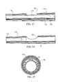
- Figure 13 illustrates the cross-sectional configuration of the catheter 50 at the location of the cut line 13-13 in Figure 10 , which is located at the aspiration opening 104. Note that the scale of Figure 13 is larger than that of the other cross-sectional views to more clearly illustrate the various layers of the apparatus.
- the aspiration opening 104 provides fluid communication between the infusion/aspiration lumen 70 and the vascular space surrounding the catheter body 50. Further, a size of the aspiration opening 104 is preferably adequate to allow the passage of dissolved clot, as well as solid pieces of clot that have been fragmented from the solid clot matter in the vessel at the treatment site.
- the aspiration opening 104 may have a length of about 0.22 inches and a width of about 0.08 inches, although other sizes or configurations may be employed.
- the agitator 80 includes an elongate shaft 110 that is generally straight over its entire length, except along a treatment length 112 thereof, which includes a non-linear curvature.
- the agitator shaft 110 is shown in Figure 2 as having a 180° bend merely for illustration purposes. In an at-rest state, the agitator shaft 110 is generally straight except along the treatment length 112.
- the curvature of the treatment length 112 is sinusoidal, but other forms of curvature could be provided instead.
- the preferred agitator shaft 110 is generally flexible, but includes sufficient rigidity that it may be pushed distally through the infusion/aspiration lumen 70 by force applied at the proximal end of the agitator 80.
- Example materials for the agitator shaft 110 include metals, such as stainless steel or any other metal displaying good fatigue properties, and polymers, such as polytetrafluoroethylene (PTFE), polyether ether ketone (PEEK), or thermoplastic polyetherimide (ULTEMTM), or any other stiff thermoplastic polymer with good fatigue properties.
- the agitator shaft 110 is further sized to be slidably received within the infusion/aspiration lumen 70.
- An outside diameter of the agitator shaft 110 may be in the range .0385-.0425 inches, or about .0410 inches.
- the agitator 80 may include a lubricious coating, such as a PTFE or FEP coating which may be applied via heat-shrink or dip coating.
- the shaft 110 includes a stainless steel core with an outer shell or coating of PTFE and PEEK.
- the PEEK is located along the treatment length 112 only, while the PTFE covers substantially all portions of the shaft 110 and is positioned over the PEEK. Providing PEEK along the treatment length 112 facilitates forming the sinusoidal curvature, because the PEEK can be heat set to permanently assume the curved shape.
- the agitator shaft 110 extends distally from an oscillation drive unit (ODU) 114.
- the ODU 114 comprises a housing 116 that can enclose a powered drive unit (not shown).
- the powered drive unit may comprise, for example, an electric motor, or any other apparatus capable of rotating the agitator shaft 110.
- the powered drive unit may be connected to a power source (not shown), such as a battery, which may also be enclosed in the housing 116.
- An on/off switch 118 on the housing 116 may be activated to start and stop rotation/oscillation of the agitator shaft 110.
- the on/off switch 118 may include an indicator light 120, such as a light-emitting diode (LED), that provides a visual indication when the powered drive unit is activated and the agitator shaft 110 is rotating/oscillating.
- an indicator light 120 such as a light-emitting diode (LED)
- Opposite sides of the housing 116 may include raised ridges 122, or other tactile features, to facilitate gripping of the ODU 114.
- the ODU 114 is sized to be comfortably gripped with one hand.
- a distal edge 124 of the housing 116 includes a connector 126 that is configured to mate with the connector 78 at the proximal end of the catheter 50 ( Figure 1 ).
- the connector 126 may comprise a male Luer-type connector, such as a LUER-LOK ® connector, for sealing engagement with a female LUER-LOK ® connector at the proximal end of the catheter 50.
- a speed of rotation of the agitator shaft 110 may be adjustable.
- the ODU 114 further includes a speed control 128.
- the speed control 128 is a rotatable knob, but in other embodiments could comprise other configurations, such as a sliding member.
- the speed of rotation of the agitator shaft 110 may be adjustable between, for example, 500 RPM (e.g. 400-600 RPM) and 3000 RPM (e.g. 2550-3450 RPM).
- an axial position of the agitator shaft 110 relative to the ODU 114 may be adjustable.
- the ODU 114 further includes a translation bar 130.
- the translation bar 130 is operatively connected to the agitator shaft 110, such that translating the translation bar 130 along the ODU 114 moves the agitator shaft 110 away from and toward the ODU 114.
- the operator may move the translation bar 130 by, for example, cradling the ODU 114 with one hand and sliding the translation bar 130 backward and forward with the thumb of the same hand.
- the ODU 114 and the translation bar 130 may include detents (not shown) such that the agitator shaft 110 is translatable between or among discrete positions, such as three discrete positions, located along the longitudinal range of motion of the agitator shaft 110.
- the agitator shaft 110 may be continuously translatable, in other words without discrete positions.
- FIG 2A illustrates a detail view of the distal end portion of an embodiment of the agitator shaft 110, as indicated by the circle 2A-2A in Figure 2 .
- An outside diameter of the agitator shaft 110 can be substantially constant over its length, except at the distal end portion, which can include an expanded diameter distal tip portion or valve body 132.
- the distal tip portion 132 is sized to substantially correspond to an internal diameter of the infusion/aspiration lumen 70, with a slight clearance, so that the agitator 80 may be slid longitudinally within the infusion/aspiration lumen 70 without substantial difficulty.
- Figure 14 illustrates the agitator 80 engaged with the catheter body 50.
- the connectors 78, 126 on the catheter 50 and the ODU 114 are sealingly engaged to secure the agitator 80 to the catheter body 50.
- the agitator shaft 110 is received within the infusion/aspiration lumen 70, and the treatment length 54 of the catheter 50 assumes the sinusoidal shape of the treatment length 112 of the agitator shaft 110.
- movement of the translation bar 130 longitudinally translates the agitator shaft 110 within the infusion/aspiration lumen 70, as described further below.
- Figures 15 and 16 illustrate side cross-sectional views of the treatment length 54 of the catheter 50 in the region of the aspiration port, as indicated by the circle 15/16-15/16 in Figure 10 .
- the agitator shaft 110 is disposed within the infusion/aspiration lumen 70.
- the distal tip portion 132 substantially blocks fluid flow through the infusion/aspiration lumen 70.
- either of infusion or aspiration may be performed through the lumen 70, as described below.
- the agitator shaft 110 is linearly translatable within the infusion/aspiration lumen 70 under the influence of the translation bar 130.
- the operator may translate the translation bar 130 proximally and distally to adjust the relative positions of the distal tip portion 132 and the aspiration opening 104, as described below.
- Figure 16 illustrates the agitator shaft 110 with the distal tip portion 132 positioned proximally of the aspiration opening 104.
- fluid communication between the infusion/aspiration port 68 ( Figure 1 ) and the aspiration opening 104 is substantially blocked.
- This position of the distal tip portion 132 may thus be referred to as the infusion position, and may correspond to a second, or middle position of the translation bar 130 with respect to the ODU 114.
- Figure 15 illustrates the agitator shaft 110 with the distal tip portion 132 positioned distally of the aspiration opening 104.
- fluid communication between the infusion/aspiration port 68 ( Figure 1 ) and the aspiration opening 104 is open.
- suction is applied at the infusion/aspiration port 68, it creates suction in the infusion/aspiration lumen 70, which in turn creates suction at the aspiration opening 104.
- Disrupted pieces of clot and/or fluid can thus be evacuated from the treatment site through the aspiration opening 104 and the infusion/aspiration lumen 70.
- This position of the distal tip portion 132 may thus be referred to as the aspiration position.
- the interaction of the distal tip portion 132 and the aspiration opening 104 can switch the apparatus between an infusion state and an aspiration state
- at least the distal tip portion 132 and the aspiration opening 104 may be referred to collectively as a valve, or an infusion/aspiration valve.
- the aspiration position of the distal tip portion 132 may correspond to a third, or distal most position of the translation bar 130 with respect to the ODU 114.
- the agitator shaft 110 in certain embodiments may include an inner core 134 and an outer sleeve 136.
- the inner core 134 and outer sleeve 136 may be constructed of different materials.
- the inner core 134 may be constructed of a metal, such as stainless steel
- the outer sleeve 136 may be constructed of a polymer, such as polytetrafluoroethylene (PTFE) and/or polyether ether ketone (PEEK).
- PTFE polytetrafluoroethylene
- PEEK polyether ether ketone
- the proximal balloon 56 can be located around and secured to an outer surface of the catheter 50 at a proximal end of the treatment length 54 thereof.
- the distal balloon 58 can be located around and secured to an outer surface of the catheter 50 at a distal end of the treatment length 54 thereof.
- the distal balloon 58 has been omitted from Figure 10 for clarity.
- the balloons 56, 58 can be secured to the catheter 50 at either end, with an intermediate portion of each balloon 56, 58 being unsecured to the catheter 50, so that upon inflation the balloons 56, 58 assume a spheroid shape or other similar shape suitable for occluding a vessel.
- the shape of the inflated balloons 56, 58 should not be interpreted as limiting. Any expanded shape suitable for occluding a vessel, such as a torus or any other shape, is within the scope of the present disclosure.
- the balloons 56, 58 may be constructed of one or more materials that are preferably durable and elastic.
- the balloons 56, 58 may be constructed of a thermoplastic elastomer, such as ChronoPrene TM , or other compliant polymers such as ChronoFLEX TM , Polyblend TM , or Chronosil TM .
- each balloon 56, 58 may be bonded to the catheter 50.
- each balloon 56, 58 may be heat bonded to the catheter 50.
- the balloons 56, 58 may be constructed of ChronoPrene TM
- the catheter distal section 84 may be constructed of a polyether block amide.
- ChronoPrene and polyether block amide do not heat bond well to one another, and are subject to delamination. The present embodiments solve this incompatibility problem by introducing a tie layer 138 between each balloon and the catheter 50.
- Figure 17 illustrates the cross-sectional configuration of one embodiment of the catheter 50 at the location of the cut line 17-17 in Figure 4 , which is located in the proximal bond region of the proximal balloon 56.
- the tie layer 138 can be interposed between each balloon 56, 58 and the catheter 50, and act as a link between the two.
- the tie layer 138 comprises a material that bonds well with both the material of the balloons 56, 58 and the material of the catheter 50.
- the tie layer 138 may comprise a compound of a polyolefin elastomer and polyether block amide, or a compound of a polyolefin elastomer and urethane.
- the ratio of polyolefin elastomer to polyether block amide or urethane may be 60/40.
- the polyolefin elastomer may be the type sold under the trademark ENGAGE ® , available from Dow Chemical, and the polyether block amide may be the type sold under the trademark PEBAX ® , available from Arkema.
- the tie layer 138 may itself comprise more than one layer.
- the tie layer 138 may comprise two layers, with an inner layer of polyether block amide and an outer layer of polyolefin elastomer.
- the tie layer 138 provides advantages. For example, one prior art method of securing balloons to catheters involves wrapping thread around the ends of each balloon. The thread increases the overall diameter and stiffness of the device as compared to devices that don't include thread. The tie layer 138 thus enables the insertion profile of the catheter 50 to be reduced, enabling it to be used in narrower spaces. The tie layer 138 also provides greater directional specificity, reducing the likelihood of lopsided balloons adjacent to the points where they are bonded to the catheter as compared to thread-wrapped balloons.
- Figures 18-25 illustrate a method of use of the present apparatus and methods for clot disruption and evacuation.
- the operator may begin by preparing the apparatus, for example performing such steps as flushing the infusion/aspiration lumen 70 with saline, filling two balloon inflation syringes with saline and connecting them to the proximal and distal balloon inflation ports 60, 62, and/or filling a syringe with a thrombolytic solution and connecting it to the infusion/aspiration port 68.
- the operator may gain vascular access at an access site (e.g.
- the treatment site e.g., the inferior vena cava, or any of the following veins: isolated iliac, iliofemoral, isolated popliteal, isolated femoral, subclavian, or any other suitable vein or artery.
- the vessel 140 is occluded at the treatment site 142 by a clot 144 or thrombus.
- the vessel 140 may be completely occluded, or only partially occluded.
- the present embodiments are not limited to this direction of approach.
- the catheter 50 is advanced through the clot 144 until the distal balloon 58 is entirely distal of the clot 144. Advancement of the catheter 50 may be aided by a guide wire and/or an introducer sheath using standard techniques. However, for clarity those components have been omitted from the figures. If a guide wire is used, the catheter 50 may be advanced over the guide wire with the guide wire passing through the infusion/aspiration lumen 70 and the opening 102 ( Figure 9 ).
- the catheter 50 may include one or more marker bands 146 to aid in external visualization of the position of the treatment length 54 of the catheter 50.
- the catheter 50 includes a pair of radiopaque bands 146 positioned beneath each of the balloons 56, 58. Using fluoroscopy, the operator may accurately position the treatment length 54 of the catheter 50 at the treatment site 142 using the radiopaque bands 146 as a guide.
- Other external visualization techniques such as ultrasound, may be used instead of fluoroscopy, which is recited here merely as one example technique.
- the distal balloon 58 is inflated by depressing the plunger on the syringe connected to the distal balloon inflation port 62.
- the distal balloon 58 is inflated until it completely occludes the vessel 140 distal of the clot 144. Complete occlusion is advantageous to prevent fragmented pieces of the clot 144 from flowing downstream away from the treatment site 142.
- the agitator 80 is advanced through the infusion/aspiration lumen 70 of the catheter 50 until the sinusoidally curved treatment length 112 of the agitator 80 is positioned between the balloons.
- the operator connects the connectors on the proximal end of the catheter 50 and the distal edge of the ODU 114 housing 116 to secure the agitator 80 to the catheter 50.
- the operator may ensure that the translation bar 130 is in the first or second position, which correspond to infusion positions. Alternatively, the operator may postpone this step until later in the procedure.
- the proximal balloon 56 is inflated by depressing the plunger on the syringe connected to the proximal balloon inflation port 60. Again, the proximal balloon 56 is inflated until it completely occludes the vessel 140 proximal of the clot 144. At this point, the clot 144 is isolated between the inflated balloons.
- the operator next activates the ODU 114 to begin rotation/oscillation of the agitator 80.
- the operator may adjust the rotational speed of the agitator 80 using the speed control 128 ( Figure 2 ) until a desired rotational speed is achieved.
- the treatment length 112 of the agitator 80 acts to mechanically disrupt the clot 144 along the treatment length and/or to disperse lytic at the treatment site to facilitate dissolving of the clot.
- the dimensions of the treatment length 112 are such that it contacts the clot 144 when it rotates, disrupting and tearing away fragments thereof as it rotates.
- the operator While the agitator 80 rotates at the desired speed, the operator infuses a quantity of thrombolytic solution by depressing the plunger on the syringe connected to the infusion/aspiration port 68.
- the lytic travels through the infusion/aspiration lumen 70 and is distributed at the treatment site 142 through the infusion openings 108 in the catheter 50 ( Figure 12 ).
- the lytic acts to chemically break down the clot 144 so that it may be more easily disrupted by the rotating agitator 80.
- the operator may periodically infuse additional discrete quantities of thrombolytic solution as the procedure progresses.
- the operator may infuse additional lytic every thirty seconds, or every sixty seconds, or every ninety seconds, etc., until all of the lytic in the infusion/aspiration syringe has been infused.
- the operator may infuse the same quantity of lytic each time, or may vary the infused quantity from one infusion to another.
- the operator may inject a first quantity and a last quantity having the same volume, with one or more intermediate quantities having half of the volume of lytic as the first and last quantities.
- the operator may follow an infusion schedule under which the operator infuses 2cc of lytic at the beginning of the run, and an additional 1cc of lytic at the end of each of the first through ninth minutes of the run.
- the operator may adjust the longitudinal position of the treatment length 112 of the agitator 80.
- the translation bar 130 may include three discrete positions. Two of these positions have been described above with respect to Figures 15 and 16 .
- a third position, or proximal most position, may also correspond to an infusion position, in which the expanded diameter distal tip portion or valve body 132 of the agitator 80 is located proximally of the aspiration opening 104 in the sidewall of the catheter body 50.
- the clot 144 can be more effectively disrupted, because the sinusoidal curvature of the treatment length 112 is brought to bear against a greater proportion of the length of the clot 144, and because the lytic is better dispersed.
- the operator may, for example, adjust the position of the agitator 80 each time he or she infuses lytic.
- the procedure may continue with the agitator 80 rotating for a desired amount of time, such as 5-15 minutes.
- the operator may verify the effectiveness of clot 144 disruption using any desired imaging technique, such as ultrasound, fluoroscopy, etc. If the results are not satisfactory, the steps described above may be repeated. However, if the results are satisfactory, the operator may begin aspirating dissolved clot, and any fragmented pieces 146 of clot 144 that may be present, from the treatment site 142.
- Figure 23 illustrates the treatment site 142 after clot 144 disruption, with fragmented pieces 146 of the clot 144.
- the agitator 80 is not shown in Figure 23 for clarity.
- the operator may first reduce the rotational speed of the agitator 80.
- the proximal balloon 56 may then be deflated if the procedure is being performed antegrade (i.e. blood flow at the treatment site 142 is in the proximal-to-distal direction with reference to the catheter 50).
- the distal balloon 58 is deflated while the proximal balloon 56 remains inflated (not shown).
- the advantage of deflating the proximal balloon 56 for antegrade procedures and deflating the distal balloon 58 for retrogrades is that blood flow entering the treatment area pushes the disrupted clot 144 particles downstream where they are trapped by the still inflated downstream balloon.
- this direction of flow has the additional advantage of pushing the fragmented clot pieces 146 toward the aspiration opening 104 in the catheter 50, which is located closer to the distal balloon 58 than the proximal balloon 56.
- the operator next moves the translation bar 130, and hence the agitator 80, to the aspiration position in which the expanded diameter distal tip portion 132 of the agitator 80 is located distally of the aspiration opening 104 in the sidewall of the catheter body 50, as shown in Figure 15 .
- the operator then aspirates the dissolved clot, and any fragmented clot pieces 146 that may be present, from the treatment site 142 by drawing back on the plunger of the infusion/aspiration syringe.
- the operator may exchange an infusion syringe for a separate and larger aspiration syringe prior to beginning aspiration.
- the dissolved clot, fragmented clot pieces 146, along with remnants of any infused fluids and/or blood, are aspirated through the aspiration opening 104 ( Figure 25 ), and flow proximally through the infusion/aspiration lumen 70 and into the infusion/aspiration syringe.
- the operator may need to perform this step more than once to ensure that all fragmented clot pieces 146 are aspirated.
- the operator When aspiration is complete, the operator halts rotation of the agitator 80, and removes the agitator 80 from the catheter 50. The operator may then optionally reinsert a guide wire through the infusion/aspiration lumen 70. The operator then deflates the second balloon and withdraws the catheter 50.
- the catheter 50 can include only three lumens in its proximal section 82, and/or only two lumens in its distal section 84. Reducing the number of lumens enables the infusion/aspiration lumen 70 to be made larger. A larger infusion/aspiration lumen 70 enables larger fragmented clot pieces 146 to pass, making it less likely that the infusion/aspiration lumen 70 will get clogged. Reducing the number of lumens also enables "360° infusion," which is discussed above.
Abstract

Description
- The present embodiments relate to apparatus for disrupting and evacuating occlusive material from blood vessels.
- Thrombosis and atherosclerosis are ailments that result from deposition of thrombus or atheromas, respectively, in the luminal walls of blood vessels. When hardened, such deposits typically result in vascular obstruction and reduced blood flow through the lumens of affected blood vessels. Thrombosis and atherosclerosis are most common in the peripheral blood vessels that feed the limbs of the human body, and the coronary arteries, which feed the heart. Stasis, incompetent valves, and trauma in the venous circulation cause thrombosis, particularly occurring as a deep vein thrombosis in the peripheral vasculature. When such deposits accumulate in localized regions of the blood vessel, they can restrict blood flow and cause a serious health risk.
- In addition to forming in the natural vasculature, thrombosis is a serious problem in "artificial" blood vessels or autologous blood vessel grafts, particularly in peripheral femoral-popliteal and coronary bypass grafts and dialysis access grafts and fistulas. The creation of such artificial blood vessels requires anastomotic attachment at at least one, and usually at at least two, locations in the vasculature. Such sites of an anastomotic attachment are particularly susceptible to thrombus formation due to narrowing caused by intimal hyperplasia, and thrombus formation at these sites is a frequent cause of failure of the implanted graft or fistula. The arterio-venous grafts and fistulas that are used for dialysis access are significantly compromised by thrombosis at the sites of anastomotic attachment and elsewhere. Thrombosis often occurs to such an extent that the graft needs to be replaced within a few years or, in the worst cases, a few months.
- A variety of methods have been developed for treating thrombosis and atherosclerosis in the coronary and peripheral vasculature, as well as in implanted grafts and fistulas. Such techniques include surgical procedures, such as coronary artery bypass grafting, and minimally invasive procedures, such as angioplasty, atherectomy, thrombectomy, thrombolysis, transmyocardial revascularization, etc.
- Some techniques for treating thrombosis and atherosclerosis include dissolving clots using thrombolytic agents. Examples of thrombolytic agents include tissue plasminogen activator (tPA), streptokinase, urokinase, etc. Such thrombolytic agents may be delivered systemically or locally. When delivered locally, the treatment may be coupled with mechanical disruption of the clot and evacuation from the vessel lumen.
- The various embodiments of the present apparatus for clot disruption and evacuation have several features, no single one of which is solely responsible for their desirable attributes. Without limiting the scope of the present embodiments as expressed by the claims that follow, their more prominent features now may be discussed briefly. After considering this discussion, and particularly after reading the section entitled "Detailed Description," one will understand how the features of the present embodiments provide the advantages described herein.
- Many of the present embodiments are described as including various combinations of features and/or components. It should be understood that these combinations are merely examples. Additional embodiments may comprise combinations of features and/or components different from those described here. For example, certain features and/or components may be omitted from various embodiments and/or combined with features and/or components shown in other combinations herein.
- The present embodiments provide apparatus, and kits for disrupting and dissolving thrombus present in a patient's vasculature. The thrombus, also referred to as clot, may be present in both the arterial and venous vasculature, as well as the peripheral venous vasculature, and grafts. The present embodiments are particularly suited for treating thrombotic disease within the venous vasculature, such as thrombosis in the superficial veins, the central veins, the femoral-popliteal veins, the iliofemoral vein, etc. The present embodiments are also particularly suited for treating arterial thrombotic disease, such as thrombosis in the iliofemoral artery, the superficial femoral artery, etc.
- The present embodiments provide apparatus for infusing thrombolytic agents, aspirating dissolved clot, and any solid clot that may be present, and passing a guide wire, all through a common catheter lumen. Other embodiments may provide for separate lumens for infusing, aspirating and/or passing a guide wire. Embodiments with fewer lumens may provide the additional advantage of having a relatively small diameter compared to other devices.
- In a first aspect, apparatus for disrupting clot over a luminal length of a blood vessel according to the present embodiments comprises a catheter body having a proximal end, a distal end and at least one lumen. At least one opening along a treatment length of the catheter body allows infusion of a thrombolytic agent and/or aspiration of dissolved clot, and any solid clot that may be present. The catheter body further includes at least one radially expandable body for inhibiting flow of clot beyond the luminal length of the blood vessel.
- The dimensions and materials of the catheter body may be selected according to characteristics of a treatment site within the vasculature to be treated. For example, the catheter may be sized to be introduced percutaneously or via a cut down to the vasculature at an entry, and then be intravascularly advanced, typically over a guide wire, to the treatment site. Treatment sites in the peripheral, coronary, and cerebral vasculature may generally be approached through different access sites, and may require catheters having different lengths, diameters, and flexibilities.
- The luminal length of the blood vessel to be treated may be at least 3 cm, at least 10 cm, in the range from 3 cm to 100 cm, and usually from 5 cm to 55 cm. The length of thrombotic disease being treated may vary depending on the location of the disease within the vasculature. For example, deep vein thrombosis is often spread over a length in the range from 5 cm to 100 cm. The apparatus and methods of the present embodiments are capable of treating disease spread over these lengths as described in more detail below.
- The apparatus of the present embodiments need not be adapted to treat the entire length of the diseased region at once. It will often be possible and in some cases desirable to treat discrete lengths within the entire diseased region separately. Such discrete lengths may be treated successively, e.g., by axially translating the treatment device within the blood vessel being treated. Alternatively, the segments could be treated using different devices, optionally introduced from different introduction sites in the vasculature.
- When the blood vessel is a vein, the target site may be selected from the vena cava, the iliac vein, the femoral vein, the popliteal vein, the common iliac vein, the external iliac vein, the brachial vein, the subclavian vein, or any other vein. When the target blood vessel is an artery, the target site may be selected from the internal iliac artery, the external iliac artery, the popliteal artery, the coronary arteries, the superficial femoral artery, the brachial artery, or any other artery.
- In various embodiments, the at least one opening in the treatment length of the catheter may include one opening in a side wall of the lumen of the catheter body, multiple smaller spaced-apart openings in the lumen, a combination of multiple smaller openings and one larger opening, etc. Generally, the at least one opening may have any suitable configuration for infusing an agent and/or aspirating dissolved clot, and any solid clot that may be present.
- Some of the present embodiments further include a mechanical agitator along the treatment length of the catheter body for mechanically agitating clot at the treatment site and/or for dispersing lytic at the treatment site. The mechanical agitator may have a wide variety of specific configurations. For example, the mechanical agitator may comprise a radially expansible agitator that is rotatable and/or axially translatable within the catheter body. In certain embodiments, the radially expansible agitator may be self-expanding. For example, it may comprise a resilient element that may be radially constrained to have a low profile (small diameter) and may be freed from radial constraint to have an enlarged profile (large diameter) with a non-linear geometry. Radial constraint may be provided by a sleeve or sheath that may be axially advanced and retracted relative to the catheter body to cover and uncover the radially expansible agitator. In this way, the catheter may be introduced to a treatment site within the vasculature with the expansible agitator covered (and thus radially constrained). After the desired treatment site is reached, the sheath or sleeve may be axially retracted to release the radially expansible agitator so that it expands to engage the clot in the blood vessel. The agitator may then be rotated and/or axially translated to engage and disrupt the clot in combination with the release of a thrombolytic agent, as described in more detail below. Such rotation, oscillation, and/or translation may be performed using a motor drive unit operatively connected to the agitator, or may be performed manually in whole or in part.
- In an alternative embodiment, the radially expansible agitator may comprise a resilient element that may be axially shortened to assume an enlarged profile having a non-linear geometry. For example, a self-expanding resilient element may be straightened (tensioned) by initially positioning a rod or stylet therein in order to lengthen the element and cause it to straighten to a low profile diameter. The agitator may then be expanded by retracting the rod or stylet to release the agitator from tension and permit the agitator to radially expand as a result of the agitator's inherent spring force. Alternatively, the agitator may be formed to have a generally straight, low profile configuration and be actively caused to radially expand by pulling on a rod or wire to cause axial shortening.
- The agitator may have a variety of specific geometries, such as a helical geometry, a spiral geometry, a serpentine geometry, a zig-zag geometry, an alternating helix geometry (e.g., two or more helical geometries in tandem where successive helixes are wound in opposite directions), and/or a variety of other random geometries. The geometries may be such that the resilient element can engage against and penetrate into the clot within a blood vessel as the resilient element is radially expanded. As the resilient element is thereafter rotated and/or axially translated, the element then mechanically engages and disrupts the clot. By simultaneously introducing the thrombolytic agent directly to the region that is being mechanically engaged by the agitator, disruption and dissolution of the clot is significantly enhanced.
- In the present embodiments that include a mechanical agitator, the apparatus may be configured to release the thrombolytic agent along substantially the entire length of the agitator that is in contact with the clot to be disrupted. In this way, the thrombolytic agent may be released at the point of mechanical agitation, resulting in both improved distribution of the thrombolytic agent into the clot as well as improved disruption and dissolution of the clot.
- In certain embodiments, the agitator may be configured as a tube having a thrombolytic agent delivery lumen therein. The tube may have agent delivery ports and/or porous regions to permit the release of the thrombolytic agent at the treatment site. In this way, the thrombolytic agent may be delivered while the agitator is deployed within the catheter.
- The clot disruption and dissolution apparatus of the present embodiments may further comprise means for isolating at least one end of the treatment site to reduce blood flow through the region being treated. For example, at least one balloon may be provided on the catheter body distally or proximally of the agitator and thrombolytic agent distribution region. When only a single balloon is used for isolation, it is preferably downstream from the treatment site. This arrangement inhibits the loss of the thrombolytic agent as well as the release of emboli downstream. Preferably, isolation means are provided on both the distal and proximal sides of the agitator and thrombolytic agent distribution region. The isolation means may comprise a pair of axially spaced-apart balloons disposed on the catheter body. Optionally, one of the balloons is disposed on a separate, telescoping portion of the catheter body in order to permit length adjustment of the region to be isolated. Alternatively, a variety of other isolation means, such as deployable flanges, malecot structures, expansible braids, etc, could also be employed.
- In another apparatus aspect, the present embodiments provide an apparatus for disrupting clot over a target region of a blood vessel. The apparatus comprises a catheter body having a proximal end and a distal end. An agitator is disposed near the distal end for mechanically agitating clot over the target region. A port near the distal end is in fluid communication with an agent supply source for distributing an agent along the target region.
- In many embodiments, the agent will comprise a thrombolytic agent, which may provide an enzymatic action to break down fibrin clot matrix. A variety of other agents may also be used, including group IIb/IIIa Inhibitors (to inhibit fibrinogen binding site of platelet membrane), other anti-platelet agents, anti-thrombin agents and agents directed toward prevention of restenosis (which may inhibit coagulation and/or inhibit restenosis by decreasing smooth muscle proliferation and migration), gene therapeutic agents (for preventing restenosis and promoting angiogenesis), chemotherapeutic agents (generally designed to treat malignancies), imaging media, and/or other potential agents.
- The present invention allows for a wide variety of particular treatment protocols. For example, the agitator may be driven at different and/or variable speeds. The agitator may be rotated and/or oscillated at speeds in the range from 0 rpm to 50,000 rpm, preferably from 50 rpm to 5,000 rpm. The speeds may be set and/or adjusted at a wide variety of particular rotational speeds within these ranges. In some cases, the direction of the rotation may be reversed during the course of the procedure. The agitator may further be axially advanced or retracted during the course of treatment to enhance the disruption of the clot and introduction of the thrombolytic into the clot.
- The present invention may further comprise aspiration of the disrupted clot from the treatment site. Aspiration may be accomplished using a lumen or lumens within the sheath and/or agitator to withdraw the disrupted clot. Optionally, mechanical means, such as an Archimedes screw or other pump, may be incorporated into the catheter to enhance the aspiration and removal of the disrupted clot. In other embodiments, such a pump may be mounted to a separate structure, such as to a sheath removably disposed over the catheter, an inner structure removably disposed within a lumen of the catheter, etc. Still further embodiments may rely on an aspiration means that remains outside the patient, such as a syringe, vacuum container, etc.
- In some embodiments, blood may be periodically or continuously introduced into the treatment region. tPA acts on plasminogen within the vasculature to breakup thrombus. If the treatment region of the present embodiments are isolated, it may be beneficial to introduce fresh blood containing plasma in order to enhance the activity of the thrombolytic agent, particularly tPA. Most simply, fresh blood could be introduced by periodically opening an isolation balloon that isolates the treatment region.
- The present invention can rely on two or more of the treatment catheters to be used simultaneously. For example, in the treatment of arterio-venous grafts, it is possible to introduce two treatment catheters according to the present embodiments, each of which has a balloon or other occlusion device at its distal end, to an A-V graft at a point near its middle. By introducing the two treatment catheters in opposite directions, the graft may be isolated very close to the points at which it is anastomosed to the natural vasculature. After such isolation is achieved, the interior of the A-V graft can then be cleaned out according to the methods of the present embodiments, and preferably the released clot and thrombus may be withdrawn through an access sheath to the A-V graft.
- The present embodiments still further comprise kits, including a catheter having an agitator and a thrombolytic agent delivery means. The kits further include instructions for use according to any of the methods set forth above and/or below. In addition to the catheter and the instructions for use, the kits may further comprise packaging, such a box, pouch, tray, tube, bag, etc. that holds the catheter and the instructions for use. The catheter may be maintained sterile within the package, and the instructions for use may be printed on a separate package insert or piece of paper. Alternatively, the instructions for use may be printed in whole or in part on a portion of the packaging.
- One of the present embodiments comprises apparatus for disrupting a clot in a blood vessel, the apparatus comprising: a catheter body having a proximal length and a treatment length; at least one port along the proximal length of the catheter body; at least one infusion opening along the treatment length of the catheter body; at least one aspiration opening along the treatment length of the catheter body; a first lumen within the catheter body in fluid communication with the infusion opening and in fluid communication with the aspiration opening; a valve member along the treatment length of the catheter body, the valve being configured to selectively open and close fluid communication between the port and the aspiration opening; and an agitator that is translatable longitudinally within the first lumen. In a further aspect of the present embodiment, the valve member comprises a body that is translatable longitudinally within the first lumen. In a further aspect of the present embodiment, the body comprises a first position located proximally of the aspiration opening and a second position located distally of the aspiration opening. In a further aspect of the present embodiment, when the body is in the first position the apparatus is configured to infuse a thrombolytic agent into the vessel through the first lumen and the infusion opening, and when the body is in the second position the apparatus is configured to aspirate dissolved clot, and any solid clot that may be present, from the vessel through the aspiration opening and the first lumen. A further aspect of the present embodiment comprises an aspiration source; wherein when the body is in the first position the body substantially blocks fluid communication within the first lumen between the aspiration opening and the aspiration source, and when the body is in the second position the body does not block fluid communication within the first lumen between the aspiration opening and the aspiration source. A further aspect of the present embodiment comprises an infusion source; wherein when the body is in the first position the body substantially blocks fluid communication within the first lumen between the aspiration opening and the infusion source, the body therefore being configured to cause fluid flowing from the infusion source to flow out of the first lumen through the at least one infusion opening. In a further aspect of the present embodiment, the agitator comprises an elongate member having a non-linear portion along the treatment length of the catheter body. In a further aspect of the present embodiment, the body is located in a distal portion of the agitator and is translatable therewith along the first lumen. A further aspect of the present embodiment comprises a first expandable member along the treatment length of the catheter body, the first expandable member defining a first expandable internal volume. A further aspect of the present embodiment comprises a second lumen within the catheter body in fluid communication with the first expandable internal volume of the first expandable member. A further aspect of the present embodiment comprises a second expandable member along the treatment length of the catheter body, the second expandable member defining a second expandable internal volume. A further aspect of the present embodiment comprises a third lumen within the catheter body in fluid communication with the second expandable internal volume of the second expandable member. In a further aspect of the present embodiment, the second lumen terminates at the first expandable internal volume of the first expandable member and the third lumen terminates at the second expandable internal volume of the second expandable member. In a further aspect of the present embodiment, the infusion opening and the aspiration opening are located between the first and second expandable members. In a further aspect of the present embodiment, the at least one infusion opening comprises a plurality of infusion openings that are spaced radially around the catheter body, over a radial span of greater than 180° about the longitudinal axis of the catheter body. In a further aspect of the present embodiment, the infusion openings are located on a portion of the catheter body that comprises no lumens other than the first lumen and the second lumen, the first lumen and the second lumen being collectively sufficient to facilitate infusion through the infusion openings, aspiration through the aspiration opening, and expansion of one of the expandable members. In a further aspect of the present embodiment, the catheter body comprises a proximal portion and a distal portion secured to one another at a joint, and the first expandable member surrounds the joint. In a further aspect of the present embodiment, the joint is a butt joint. In a further aspect of the present embodiment, the at least one infusion opening comprises a plurality of infusion openings, and the infusion openings are spaced from one another both radially and longitudinally with respect to the treatment length of the catheter body. In a further aspect of the present embodiment, the infusion openings are grouped in groups of three, with each group of three infusion openings being located at a same position along the treatment length of the catheter body. In a further aspect of the present embodiment, the infusion openings in each group of three infusion openings are uniformly radially spaced 120° from one another. In a further aspect of the present embodiment, the agitator is configured to mechanically disrupt the clot and/or to disperse lytic to facilitate dissolving the clot.
- Another of the present embodiments comprises apparatus for disrupting a clot in a blood vessel, the apparatus comprising: a catheter body having a proximal length and a treatment length; at least one port along the proximal length of the catheter body; at least one infusion opening along the treatment length of the catheter body; at least one aspiration opening along the treatment length of the catheter body; a first lumen within the catheter body in fluid communication with the infusion opening and in fluid communication with the aspiration opening; means for selectively opening and closing fluid communication between the port and the aspiration opening; and an agitator that is translatable longitudinally within the first lumen. In a further aspect of the present embodiment, the means includes a body portion located within the first lumen. In a further aspect of the present embodiment, the body portion is translatable longitudinally between a first position located proximally of the aspiration opening and a second position located distally of the aspiration opening. In a further aspect of the present embodiment, when the body portion is in the first position the apparatus is configured to infuse a thrombolytic agent into the vessel through the first lumen and the infusion opening, and when the body portion is in the second position the apparatus is configured to aspirate dissolved clot, and any solid clot that may be present, from the vessel through the aspiration opening and the first lumen. A further aspect of the present embodiment comprises an aspiration source; wherein when the body is in the first position the body substantially blocks fluid communication within the first lumen between the aspiration opening and the aspiration source, and when the body is in the second position the body does not block fluid communication within the first lumen between the aspiration opening and the aspiration source. A further aspect of the present embodiment comprises an infusion source; wherein when the body is in the first position the body substantially blocks fluid communication within the first lumen between the aspiration opening and the infusion source, the body therefore being configured to cause fluid flowing from the infusion source to flow out of the first lumen through the at least one infusion opening. In a further aspect of the present embodiment, the agitator comprises an elongate member having a non-linear portion along the treatment length of the catheter body. In a further aspect of the present embodiment, the body portion is located in a distal portion of the agitator and is translatable therewith along the first lumen. In a further aspect of the present embodiment, the at least one infusion opening comprises a plurality of infusion openings that are spaced radially around the catheter body, over a radial span of greater than 180° about the longitudinal axis of the catheter body. In a further aspect of the present embodiment, the infusion openings are located on a portion of the catheter body that comprises no lumens other than the first lumen and a second lumen, the first lumen and the second lumen being collectively sufficient to facilitate infusion through the infusion openings, aspiration through the aspiration opening, and expansion of one of the expandable members. In a further aspect of the present embodiment, the agitator is configured to mechanically disrupt the clot and/or to disperse lytic to facilitate dissolving the clot.
- Another of the present embodiments comprises apparatus for disrupting a clot in a blood vessel, the apparatus comprising: a catheter body having a proximal length and a treatment length; at least one port along the proximal length of the catheter body; at least a first opening along the treatment length of the catheter body; a first lumen within the catheter body in fluid communication with the opening; a body member axially translatable within the first lumen between a first position located proximally of the opening and a second position located distally of the opening; and an agitator that is translatable longitudinally within the first lumen. In a further aspect of the present embodiment, when the body member is in the first position fluid communication between the port and the opening is closed, and when the body member is in the second position fluid communication between the port and the opening is open. In a further aspect of the present embodiment, the agitator comprises an elongate member having a non-linear portion along the treatment length of the catheter body. In a further aspect of the present embodiment, the body member is located in a distal portion of the agitator and is translatable therewith along the first lumen. A further aspect of the present embodiment comprises at least a second opening along the treatment length of the catheter body. In a further aspect of the present embodiment, the first opening is configured for aspiration of dissolved clot, and any solid clot that may be present, from within the vessel and the second opening is configured for infusion of a thrombolytic agent into the vessel. A further aspect of the present embodiment comprises an aspiration source; wherein when the body is in the first position the body substantially blocks fluid communication within the first lumen between the aspiration opening and the aspiration source, and when the body is in the second position the body does not block fluid communication within the first lumen between the aspiration opening and the aspiration source. A further aspect of the present embodiment comprises an infusion source; wherein when the body is in the first position the body substantially blocks fluid communication within the first lumen between the aspiration opening and the infusion source, the body therefore being configured to cause fluid flowing from the infusion source to flow out of the first lumen through the at least one infusion opening. In a further aspect of the present embodiment, the agitator is configured to mechanically disrupt the clot and/or to disperse lytic to facilitate dissolving the clot.
- In a further aspect of the present embodiment, the agitating mechanism comprises an elongate member having a non-linear portion along the treatment length of the catheter body. In a further aspect of the present embodiment, activating the agitating mechanism comprises rotating and/or axially translating the agitating mechanism within the blood vessel and against the clot. In a further aspect of the present embodiment, the occluding body is located in a distal portion of the agitating mechanism, and advancing the occluding body within the first lumen comprises advancing the agitating mechanism. In a further aspect of the present embodiment, wherein positioning the occluding body proximally of the aspiration opening further comprises directing fluid flow from an infusion source through the infusion opening and not through the aspiration opening. A further aspect of the present embodiment comprises expanding a first expandable member located along the treatment length of the catheter body until the vessel is occluded by the first expandable member. A further aspect of the present embodiment comprises expanding a second expandable member located along the treatment length of the catheter body until the vessel is occluded by the second expandable member, wherein the first and second expandable members are located on either side of the clot. In a further aspect of the present embodiment, expanding the first expandable member comprises introducing fluid into a first expandable internal volume of the first expandable member through a second lumen of the catheter body. In a further aspect of the present embodiment, expanding the second expandable member comprises introducing fluid into a second expandable internal volume of the second expandable member through a third lumen of the catheter body. In a further aspect of the present embodiment, the second lumen terminates at the first expandable internal volume of the first expandable member and the third lumen terminates at the second expandable internal volume of the second expandable member. In a further aspect of the present embodiment, the infusion opening and the aspiration opening are located between the first and second expandable members. In a further aspect of the present embodiment, the catheter body comprises a proximal portion and a distal portion secured to one another at a joint, and the first expandable member surrounds the joint. In a further aspect of the present embodiment, the joint is a butt joint. In a further aspect of the present embodiment, infusing the thrombolytic agent comprises forming a plurality of outflows of the infused agent that are spaced radially around the catheter body, over a radial span of greater than 180° about the longitudinal axis of the catheter body. In a further aspect of the present embodiment, the outflows are formed along a portion of the catheter body that comprises the first lumen and a second lumen; further comprising achieving infusion via the plurality of outflows, aspiration through the aspiration opening, and expansion of an expandable member, all by using no catheter body lumens other than the first lumen and the second lumen. In a further aspect of the present embodiment, the at least one infusion opening comprises a plurality of infusion openings, and the infusion openings are spaced from one another both radially and longitudinally with respect to the treatment length of the catheter body. In a further aspect of the present embodiment, the infusion openings are grouped in groups of three, with each group of three infusion openings being located at a same position along the treatment length of the catheter body. In a further aspect of the present embodiment, the infusion openings in each group of three infusion openings are uniformly radially spaced 120° from one another.
- The various embodiments of the present apparatus for clot disruption and evacuation now may be discussed in detail with an emphasis on highlighting the advantageous features. These embodiments depict the novel and non-obvious apparatus and methods shown in the accompanying drawings, which are for illustrative purposes only. These drawings include the following figures, in which like numerals indicate like parts:
-
Figure 1 is a top plan view of a catheter for use in an apparatus for clot disruption and evacuation, and lytic distribution, according to one of the present embodiments; -
Figure 2 is a top plan view of an agitator for use in an apparatus for clot disruption and evacuation, and lytic distribution, according to one of the present embodiments; -
Figure 2A is a detail view of the portion ofFigure 2 indicated by thecircle 2A-2A; -
Figure 3 is a cross-sectional view of the apparatus ofFigure 3 taken along the line 3-3; -
Figure 4 is a detail view of the portion ofFigure 1 indicated by the circle 4-4; -
Figures 5-8 are cross-sectional views of the apparatus ofFigure 4 taken along the lines 5-5, 6-6, 7-7, 8-8, respectively; -
Figure 9 is a side cross-sectional detail view of a distal end of the catheter ofFigure 1 ; -
Figure 10 is a detail view of the portion ofFigure 1 indicated by the circle 10-10; -
Figure 11 is a cross-sectional view of the apparatus ofFigure 10 taken along the line 11-11; -
Figure 12 is a cross-sectional view of the apparatus ofFigure 4 taken along the line 12-12; -
Figure 13 is a cross-sectional view of the apparatus ofFigure 10 taken along the line 13-13; -
Figure 14 is a top plan view of the catheter ofFigure 1 coupled with the agitator ofFigure 2 ; -
Figures 15 and 16 are side cross-sectional detail views of the portion ofFigure 10 indicated by the circle 15/16-15/16; -
Figure 17 is a cross-sectional view of the apparatus ofFigure 4 taken along the line 17-17; and -
Figures 18-25 are side elevation views of a method for clot disruption and evacuation according to one of the present embodiments. - The following detailed description describes the present embodiments with reference to the drawings. In the drawings, reference numbers label elements of the present embodiments. These reference numbers are reproduced below in connection with the discussion of the corresponding drawing features.
- The embodiments of the present apparatus for clot disruption and evacuation are described below with reference to the figures. These figures, and their written descriptions, indicate that certain components of the apparatus are formed integrally, and certain other components are formed as separate pieces. Components shown and described herein as being formed integrally may in alternative embodiments be formed as separate pieces. Components shown and described herein as being formed as separate pieces may in alternative embodiments be formed integrally. Further, as used herein the term integral describes a single unitary piece.
- Directional terms used herein, such as proximal, distal, upper, lower, clockwise, counterclockwise, etc., are used with reference to the configurations shown in the figures. For example, a component that is described as rotating clockwise when viewed from the perspectives shown in the figures may be described as rotating counterclockwise when viewed from the opposite perspective. Furthermore, the present embodiments may be modified by altering or reversing the positions or directions of movement of various components. Accordingly, directional terms used herein should not be interpreted as limiting.
-
Figures 1 and 2 illustrate one embodiment of apparatus for disrupting a clot in a blood vessel. With reference toFigure 1 , the apparatus comprises acatheter body 50 having aproximal length 52 and atreatment length 54. Aproximal balloon 56 and adistal balloon 58 are located along thetreatment length 54, and define proximal and distal ends, respectively, of thetreatment length 54. Theproximal length 52 includes a plurality of ports, including a proximalballoon inflation port 60 and a distalballoon inflation port 62. With reference toFigure 3 , the proximalballoon inflation port 60 is in fluid communication with an interior of theproximal balloon 56 through a proximalballoon inflation lumen 64 that extends through thecatheter body 50 between theport 60 and theballoon 56. The distalballoon inflation port 62 is in fluid communication with an interior of thedistal balloon 58 through a distalballoon inflation lumen 66 that extends through thecatheter body 50 between theport 62 and theballoon 58, and which is preferably separate from, and not in fluid communication with, the proximalballoon inflation lumen 64. With reference toFigure 1 , theproximal length 52 further includes an infusion/aspiration port 68 that is in fluid communication with a plurality of infusion openings and an aspiration opening (shown in later figures) located along thetreatment length 54 through a combined infusion/aspiration lumen 70 (Figure 3 ) that extends through thecatheter body 50 from theport 68 to the openings. - With continued reference to
Figure 1 , each of theports tubular portion 72 that extends perpendicularly from thecatheter body 50. In alternative embodiments, thetubular portions 72 may extend from thecatheter body 50 at a non-perpendicular angle. Theballoon inflation ports catheter body 50, and the infusion/aspiration port 68 is located on a second, opposite, side of thecatheter body 50 and proximally of theballoon inflation ports ports tubular portions 72 spaced from thecatheter body 50, each port includes aconnector 74 configured to receive an infusion/aspiration device, such as a syringe (not shown). For example, theconnector 74 may comprise a Luer-type connector, such as a LUER-LOK® connector or a LUER-SLIP® connector. - The
proximal length 52 of thecatheter body 50 can further comprise a substantially rigidtubular section 76 from which each of theports connector 78 configured to receive anagitator 80, which is described below and illustrated inFigure 2 . For example, theconnector 78 may comprise a Luer-type connector, such as a LUER-LOK® connector. The combined infusion/aspiration lumen 70 can extend through the proximal end of thetubular section 76, i.e. the proximal end includes an opening corresponding to the location of the infusion/aspiration lumen 70. However, theballoon inflation lumens balloons - With continued reference to
Figure 1 , and as described in further detail below, thecatheter body 50 comprises aproximal section 82 and adistal section 84. Theproximal section 82 extends from the proximal end to a location beneath the proximal balloon 56 (illustrated in further detail below). Thedistal section 84 is joined to a distal end of theproximal section 82, and extends to a distal end of thecatheter body 50. As detailed further below, the proximal anddistal sections proximal section 82 may have a greater stiffness than thedistal section 84, such that theproximal section 82 is configured for pushability while thedistal section 84 is adapted for navigating tortuous vasculature. - The
catheter body 50 is preferably sized and configured to be advanced through a patient's vasculature from a transcutaneous access site to a treatment site within the vasculature. Example dimensions for thecatheter body 50 include an outside diameter of approximately 8 French, or in the range of 4 French to 12 French, or outside diameters of .095-.097 inches and .085-.087 inches for the proximal and distal sections, respectively; and a length in the range of 50cm-200cm, or about 80cm, or about 120cm. Material(s) from which thecatheter body 50 is constructed is preferably rigid enough to allow thecatheter 50 to be pushed distally, but flexible enough to enable navigation of tortuous vasculature. Example materials for theproximal section 82 include polyether block amide (PEBAX™), or any lubricious and/or hydrophilic polymer such as nylon, polyethylene or EVA. One suitable composition comprises 39% Pebax 63D, 39% Pebax 72D, 20% BaSO4, and 2% TiO2. Similar materials may be used for thedistal section 84; however, the material of thedistal section 84 can be softer than that of theproximal section 82 so that it is more easily deflected by theagitator 80. One suitable composition comprises 78% Pebax 63D, 20% BaSO4, and 2% TiO2. -
Figure 3 illustrates the cross-sectional configuration of thecatheter 50 at the location of the line 3-3 inFigure 4 (see area 4-4 inFigure 1 ). The infusion/aspiration lumen 70 can have a circular cross-section, and occupy a majority of the cross-sectional area of the catheter 50 (e.g., 60% or more, or two-thirds or more, or about 69% in theproximal section 82 and/or 67% in the distal section 84). Each of theballoon lumens lumens aspiration lumen 70. A cross-sectional area of each of theballoon lumens aspiration lumen 70. For example, the cross-sectional area of the balloon lumen(s) can be about .0003 square inches in theproximal section 82 and about .0005 square inches in thedistal section 84, while the infusion/aspiration lumen can have a cross-sectional area of about .0034 square inches in theproximal section 82 and about .0026 square inches in thedistal section 84. - All three of the
lumens catheter 50 from theproximal length 52 to at least the location of theproximal balloon 56.Figure 4 is a detail view of the portion of thecatheter 50 indicated by the circle 4-4 inFigure 1 , which is within the region of theproximal balloon 56. The proximal anddistal sections proximal balloon 56. For example, the proximal anddistal sections - As discussed above, the proximal and
distal sections catheter body 50 may have different cross-sectional configurations. However, the infusion/aspiration lumen 70 extends through the entirety of thecatheter body 50, while the distalballoon inflation lumen 66 extends through portions of both the proximal anddistal sections balloon inflation lumen 64 extends through a portion of only the proximal section 82 (although arrangements other than the foregoing may be employed). Thus, the cross-sectional configuration of theproximal section 82 of thecatheter body 50 can change toward the distal end thereof. With reference toFigure 4 , theproximal section 82 may be heated in aheating zone 88 that extends from the butt joint 86 to a location proximal of theproximal balloon 56. The heating causes the material of thecatheter body 50 to melt and reflow. An outer diameter of thecatheter 50 reduces slightly, creating anecked region 90 at a proximal end of theheating zone 88. During the heating process, mandrels (not shown) may be inserted through the infusion/aspiration lumen 70, the proximalballoon inflation lumen 64, and the distalballoon inflation lumen 66, so that these lumens do not completely collapse. -
Figure 5 illustrates the cross-sectional configuration of an embodiment of thecatheter 50 at the location of the cut line 5-5 inFigure 4 , which is within theheating zone 88 just distal of thenecked region 90. ComparingFigures 3 and5 , the diameter of the infusion/aspiration lumen 70 may be decreased in theheating zone 88. The sizes of theballoon inflation lumens Figure 3 . This cross-sectional configuration of thecatheter body 50 can extend toward the distal end of theproximal section 82, until just proximal of the distal end.Figure 6 illustrates the cross-sectional configuration of thecatheter 50 at the location of the cut line 6-6 inFigure 4 , which is just proximal of the distal end. The mandrel inserted into the proximalballoon inflation lumen 64 during heating may not extend through the distal end of thecatheter 50, such that the proximalballoon inflation lumen 64 completely collapses distally of the mandrel. This configuration seals the proximalballoon inflation lumen 64 so that fluid injected into the proximalballoon inflation lumen 64 cannot flow past the distal end of theproximal section 82 of thecatheter 50, and is instead forced into theproximal balloon 56 through a proximal balloon inflation opening 92 (Figure 7 ) in the side wall of thecatheter 50, as described further below. Instead of or in addition to the heating procedure described herein, other techniques (such as the use of a plug and/or adhesive) may be used to seal the distal end of the proximalballoon inflation lumen 64. -
Figure 7 illustrates an embodiment of the cross-sectional configuration of thecatheter 50 at the location of the cut line 7-7 inFigure 4 , which is at the location of the proximalballoon inflation opening 92. The proximalballoon inflation opening 92 provides a fluid path from the proximalballoon inflation lumen 64 to an interior space of theproximal balloon 56. Theproximal balloon 56 can thus be inflated by infusing fluid, such as saline, into theproximal balloon 56 through the proximalballoon inflation lumen 64, through the proximalballoon inflation opening 92, and into the interior space of theproximal balloon 56. Theproximal balloon 56 can also be deflated by aspirating the fluid along the same path in the reverse order. - As discussed above, constructing the
catheter body 50 from separate proximal anddistal sections distal sections proximal section 82 may have greater rigidity compared to a material of thedistal section 84. Such a configuration enables thecatheter body 50 to be advanced through the body by pushing from the proximal end, while maintaining flexibility along thetreatment length 54 so that thetreatment length 54 can more easily navigate tortuous vasculature and can accommodate anagitator shaft 110 having a larger amplitude along thetreatment length 112. Example materials for the proximal anddistal sections - Another advantage of constructing the
catheter body 50 from separate proximal anddistal sections Figure 8 illustrates the cross-sectional configuration of thedistal section 84 of thecatheter 50, at the location of the cut line 8-8 inFigure 4 , which is just distal to the joint 86. Thedistal section 84 of thecatheter 50 can include the infusion/aspiration lumen 70 and the distalballoon inflation lumen 66, but not the proximalballoon inflation lumen 64. Thedistal section 84, lacking the proximalballoon inflation lumen 64 that theproximal section 82 includes, can thus be made separately from theproximal section 82, and the two sections can then be secured to one another at the joint 86. Both sections can be made using standard techniques, such as extrusion, or any other processe(s). Alternatively, both sections can be made as a single piece or a single extrusion, without the joint 86. - With continued reference to
Figure 8 , the combined infusion/aspiration lumen 70 and the distalballoon inflation lumen 66 continue through thedistal section 84 of thecatheter 50 in the distal direction.Figure 9 illustrates a side cross-sectional view of an embodiment of the distal end of thecatheter 50. The distalballoon inflation lumen 66 terminates proximally of the distal end of thecatheter 50. This configuration facilitates maintaining pressure in thedistal balloon 58 when it is inflated. The combined infusion/aspiration lumen 70 extends through the distal end of thecatheter 50 such that there is anopening 94 in the distal end of thecatheter 50 corresponding to thelumen 70. However, adistal end cap 96 can be employed to close thedistal opening 94 of the infusion/aspiration lumen 70. Thedistal end cap 96 is substantially cylindrical with atapered nose portion 98. Thecap 96 fits over a reduced diameterdistal portion 100 of the catheter. A central portion of thecap 96 includes a narrow (relative to the infusion/aspiration lumen 70) opening 102 sized to allow a guide wire (not shown) to pass. The guide wire may be used when deploying thecatheter 50 according to standard techniques. Theopening 102 also provides pressure relief in the event that pressure within the infusion/aspiration lumen 70 rises. This pressure relief reduces the likelihood that fluids in thecatheter 50 will flow out the proximal end, a phenomenon known as "back bleed." -
Figure 10 is a detail view of an embodiment of the portion of thecatheter 50 indicated by the circle 10-10 inFigure 1 , which is within the region of thedistal balloon 58 and theaspiration opening 104. Thedistal balloon 58 has been omitted fromFigure 10 for clarity.Figure 11 illustrates the cross-sectional configuration of thecatheter 50 at the location of the cut line 11-11 inFigure 10 . At the location ofFigure 11 , a distalballoon inflation opening 106 in the side wall of thecatheter 50 provides a fluid path from the distalballoon inflation lumen 66 to an interior space of thedistal balloon 58. Thedistal balloon 58 can thus be inflated by infusing fluid, such as saline, into thedistal balloon 58 through the distalballoon inflation lumen 66, through the distalballoon inflation opening 106, and into the interior space of thedistal balloon 58. Thedistal balloon 58 can also be deflated by aspirating the fluid along the same path in the reverse order. - Referring back to
Figure 4 ,Figure 12 illustrates an embodiment of the cross-sectional configuration of thecatheter 50 at the location of the cut line 12-12, which is located between the proximal anddistal balloons catheter 50 can include a plurality ofinfusion openings 108 that extend from the infusion/aspiration lumen 70 radially outward and through the side wall of thecatheter 50. In the illustrated embodiment, threeinfusion openings 108 are provided at the location of the cut line 12-12. Additional such triads (or pairs, singles, etc.) ofinfusion openings 108 can be provided at axially spaced locations along the infusion/aspiration region. The axial spacing between triads may be uniform or variable. - At the location of each triad of
infusion openings 108, the threeopenings 108 can be substantially uniformly spaced from one another at about 120° apart in the circumferential direction. The illustrated number and spacing of theinfusion openings 108 is advantageous, as it provides the capability to infuse a thrombolytic agent over a radial span of substantially 360° around the outside of thecatheter 50. Such "360° infusion" enables more uniform application of the thrombolytic agent to clot matter in the region of thetreatment length 54 of thecatheter 50 to more efficiently break down the clot. 360° infusion is facilitated at least in part by termination of the proximalballoon inflation lumen 64 proximally of the locations of theinfusion openings 108. Reducing the total number of lumens in thecatheter 50 in the infusion/aspiration region leaves a larger radial portion of thecatheter 50 through which theinfusion openings 108 can extend from the infusion/aspiration lumen 70 without interfering with other lumens. - As described in further detail below, thrombolytic agent may be infused at a treatment site within a vessel by injecting the lytic at the infusion/aspiration port 68 (
Figure 1 ), where it flows into and through the infusion/aspiration lumen 70 and eventually out theinfusion openings 108. Because theinfusion openings 108 are distributed along the axial length of thecatheter body 50, it is advantageous for a diameter of each infusion opening 108 to be small compared to a diameter of the infusion/aspiration lumen 70. Such a configuration facilitates maintaining a substantially uniform infusion pressure at each infusion opening 108, as opposed to moreproximal infusion openings 108 having higher infusion pressures than moredistal infusion openings 108. For example, in certain of the present embodiments a diameter of the infusion/aspiration lumen 70 may be in the range .065-.067 inches in theproximal section 82 and .057-.059 inches in thedistal section 84, while a diameter of each infusion opening 108 may be in the range .0025-.0055 inches. - In certain embodiments, locations of at least some of the triads (or pairs, singles, groups of four, etc.) of
infusion openings 108 may be located atpeaks 150 of thetreatment length 112 of the agitator shaft 110 (Figure 2 ). Such a configuration locates theinfusion openings 108 as close as possible to the wall of the vessel at the treatment site for more effective chemical breakdown of the clot. - With reference to
Figure 10 , the sidewall of thecatheter body 50 can further include anaspiration opening 104 located in the infusion/aspiration region. In the illustrated embodiment, the aspiration opening 104 is just proximal of thedistal balloon 58. That is, the aspiration opening 104 is closer to thedistal balloon 58 than it is to theproximal balloon 56. This configuration provides advantages. For example, during a treatment procedure where the treatment site is accessed from an upstream location (antegrade), an operator may deflate theproximal balloon 56 prior to aspirating dissolved clot, and any solid clot that may be present, from the treatment site. Blood will thus flow toward the treatment site and push any fragmented matter toward the aspiration opening 104, making it more likely that all of the fragmented matter will be aspirated out of the vasculature. Processes for using the present embodiments are described in further detail below. -
Figure 13 illustrates the cross-sectional configuration of thecatheter 50 at the location of the cut line 13-13 inFigure 10 , which is located at theaspiration opening 104. Note that the scale ofFigure 13 is larger than that of the other cross-sectional views to more clearly illustrate the various layers of the apparatus. With reference toFigure 13 , the aspiration opening 104 provides fluid communication between the infusion/aspiration lumen 70 and the vascular space surrounding thecatheter body 50. Further, a size of the aspiration opening 104 is preferably adequate to allow the passage of dissolved clot, as well as solid pieces of clot that have been fragmented from the solid clot matter in the vessel at the treatment site. These dislodged pieces can thus be drawn into the infusion/aspiration lumen 70 through theaspiration opening 104 and evacuated from the vessel, as described in detail below. For example, the aspiration opening 104 may have a length of about 0.22 inches and a width of about 0.08 inches, although other sizes or configurations may be employed. - Certain disclosed embodiments advantageously enable infusion of thrombolytic agent and aspiration of dissolved clot, and any solid clot that may be present, to be performed through the same lumen (the infusion/aspiration lumen 70) in the
catheter 50. Infusion and aspiration can be achieved with the aid of the agitator 80 (Figure 2 ), which can be slidably received within the infusion/aspiration lumen 70, as described below. With reference toFigure 2 , theagitator 80 includes anelongate shaft 110 that is generally straight over its entire length, except along atreatment length 112 thereof, which includes a non-linear curvature. (Theagitator shaft 110 is shown inFigure 2 as having a 180° bend merely for illustration purposes. In an at-rest state, theagitator shaft 110 is generally straight except along thetreatment length 112.) In the illustrated embodiment, the curvature of thetreatment length 112 is sinusoidal, but other forms of curvature could be provided instead. - The
preferred agitator shaft 110 is generally flexible, but includes sufficient rigidity that it may be pushed distally through the infusion/aspiration lumen 70 by force applied at the proximal end of theagitator 80. Example materials for theagitator shaft 110 include metals, such as stainless steel or any other metal displaying good fatigue properties, and polymers, such as polytetrafluoroethylene (PTFE), polyether ether ketone (PEEK), or thermoplastic polyetherimide (ULTEM™), or any other stiff thermoplastic polymer with good fatigue properties. Theagitator shaft 110 is further sized to be slidably received within the infusion/aspiration lumen 70. An outside diameter of theagitator shaft 110 may be in the range .0385-.0425 inches, or about .0410 inches. Theagitator 80 may include a lubricious coating, such as a PTFE or FEP coating which may be applied via heat-shrink or dip coating. - In one embodiment, the
shaft 110 includes a stainless steel core with an outer shell or coating of PTFE and PEEK. The PEEK is located along thetreatment length 112 only, while the PTFE covers substantially all portions of theshaft 110 and is positioned over the PEEK. Providing PEEK along thetreatment length 112 facilitates forming the sinusoidal curvature, because the PEEK can be heat set to permanently assume the curved shape. - With reference to
Figure 2 , theagitator shaft 110 extends distally from an oscillation drive unit (ODU) 114. TheODU 114 comprises ahousing 116 that can enclose a powered drive unit (not shown). The powered drive unit may comprise, for example, an electric motor, or any other apparatus capable of rotating theagitator shaft 110. The powered drive unit may be connected to a power source (not shown), such as a battery, which may also be enclosed in thehousing 116. An on/offswitch 118 on thehousing 116 may be activated to start and stop rotation/oscillation of theagitator shaft 110. The on/offswitch 118 may include anindicator light 120, such as a light-emitting diode (LED), that provides a visual indication when the powered drive unit is activated and theagitator shaft 110 is rotating/oscillating. Opposite sides of thehousing 116 may include raisedridges 122, or other tactile features, to facilitate gripping of theODU 114. Preferably, theODU 114 is sized to be comfortably gripped with one hand. Adistal edge 124 of thehousing 116 includes aconnector 126 that is configured to mate with theconnector 78 at the proximal end of the catheter 50 (Figure 1 ). For example, theconnector 126 may comprise a male Luer-type connector, such as a LUER-LOK® connector, for sealing engagement with a female LUER-LOK® connector at the proximal end of thecatheter 50. In certain embodiments, a speed of rotation of theagitator shaft 110 may be adjustable. Thus, with continued reference toFigure 2 , theODU 114 further includes aspeed control 128. In the illustrated embodiment, thespeed control 128 is a rotatable knob, but in other embodiments could comprise other configurations, such as a sliding member. When theagitator shaft 110 is activated to rotate, adjustment of thespeed control 128 adjusts a speed of rotation of theagitator shaft 110. The speed of rotation of theagitator shaft 110 may be adjustable between, for example, 500 RPM (e.g. 400-600 RPM) and 3000 RPM (e.g. 2550-3450 RPM). - Also in certain embodiments, an axial position of the
agitator shaft 110 relative to theODU 114 may be adjustable. Thus, with continued reference toFigure 2 , theODU 114 further includes atranslation bar 130. Thetranslation bar 130 is operatively connected to theagitator shaft 110, such that translating thetranslation bar 130 along theODU 114 moves theagitator shaft 110 away from and toward theODU 114. The operator may move thetranslation bar 130 by, for example, cradling theODU 114 with one hand and sliding thetranslation bar 130 backward and forward with the thumb of the same hand. In certain embodiments, theODU 114 and thetranslation bar 130 may include detents (not shown) such that theagitator shaft 110 is translatable between or among discrete positions, such as three discrete positions, located along the longitudinal range of motion of theagitator shaft 110. In other embodiments, theagitator shaft 110 may be continuously translatable, in other words without discrete positions. -
Figure 2A illustrates a detail view of the distal end portion of an embodiment of theagitator shaft 110, as indicated by thecircle 2A-2A inFigure 2 . An outside diameter of theagitator shaft 110 can be substantially constant over its length, except at the distal end portion, which can include an expanded diameter distal tip portion orvalve body 132. As described below, thedistal tip portion 132 is sized to substantially correspond to an internal diameter of the infusion/aspiration lumen 70, with a slight clearance, so that theagitator 80 may be slid longitudinally within the infusion/aspiration lumen 70 without substantial difficulty. -
Figure 14 illustrates theagitator 80 engaged with thecatheter body 50. Theconnectors catheter 50 and theODU 114 are sealingly engaged to secure theagitator 80 to thecatheter body 50. Theagitator shaft 110 is received within the infusion/aspiration lumen 70, and thetreatment length 54 of thecatheter 50 assumes the sinusoidal shape of thetreatment length 112 of theagitator shaft 110. When theagitator 80 is engaged with thecatheter body 50, movement of thetranslation bar 130 longitudinally translates theagitator shaft 110 within the infusion/aspiration lumen 70, as described further below. -
Figures 15 and 16 illustrate side cross-sectional views of thetreatment length 54 of thecatheter 50 in the region of the aspiration port, as indicated by the circle 15/16-15/16 inFigure 10 . With reference toFigure 15 , theagitator shaft 110 is disposed within the infusion/aspiration lumen 70. Thedistal tip portion 132 substantially blocks fluid flow through the infusion/aspiration lumen 70. Depending upon whether thedistal tip portion 132 is positioned proximally or distally of the aspiration opening 104, either of infusion or aspiration may be performed through thelumen 70, as described below. As discussed above, theagitator shaft 110 is linearly translatable within the infusion/aspiration lumen 70 under the influence of thetranslation bar 130. Thus, to switch between infusion and aspiration, the operator may translate thetranslation bar 130 proximally and distally to adjust the relative positions of thedistal tip portion 132 and the aspiration opening 104, as described below. - For example,
Figure 16 illustrates theagitator shaft 110 with thedistal tip portion 132 positioned proximally of theaspiration opening 104. In this position, fluid communication between the infusion/aspiration port 68 (Figure 1 ) and the aspiration opening 104 is substantially blocked. Thus, if fluid is infused through the infusion/aspiration port 68 it flows through the infusion/aspiration lumen 70 before being forced out of the infusion openings 108 (Figure 12 ) proximal of the distal tip portion 132 (which itself is proximal of the aspiration opening 104). This position of thedistal tip portion 132 may thus be referred to as the infusion position, and may correspond to a second, or middle position of thetranslation bar 130 with respect to theODU 114. - By contrast,
Figure 15 illustrates theagitator shaft 110 with thedistal tip portion 132 positioned distally of theaspiration opening 104. In this position, fluid communication between the infusion/aspiration port 68 (Figure 1 ) and the aspiration opening 104 is open. Thus, if suction is applied at the infusion/aspiration port 68, it creates suction in the infusion/aspiration lumen 70, which in turn creates suction at theaspiration opening 104. Disrupted pieces of clot and/or fluid can thus be evacuated from the treatment site through theaspiration opening 104 and the infusion/aspiration lumen 70. This position of thedistal tip portion 132 may thus be referred to as the aspiration position. Further, because the interaction of thedistal tip portion 132 and the aspiration opening 104 can switch the apparatus between an infusion state and an aspiration state, at least thedistal tip portion 132 and the aspiration opening 104 may be referred to collectively as a valve, or an infusion/aspiration valve. The aspiration position of thedistal tip portion 132 may correspond to a third, or distal most position of thetranslation bar 130 with respect to theODU 114. - With further reference to
Figure 15 , and as discussed above, theagitator shaft 110 in certain embodiments may include aninner core 134 and anouter sleeve 136. Theinner core 134 andouter sleeve 136 may be constructed of different materials. For example, theinner core 134 may be constructed of a metal, such as stainless steel, and theouter sleeve 136 may be constructed of a polymer, such as polytetrafluoroethylene (PTFE) and/or polyether ether ketone (PEEK). - With reference back to
Figure 4 , theproximal balloon 56 can be located around and secured to an outer surface of thecatheter 50 at a proximal end of thetreatment length 54 thereof. Similarly, with reference toFigure 10 , thedistal balloon 58 can be located around and secured to an outer surface of thecatheter 50 at a distal end of thetreatment length 54 thereof. Thedistal balloon 58 has been omitted fromFigure 10 for clarity. Theballoons catheter 50 at either end, with an intermediate portion of eachballoon catheter 50, so that upon inflation theballoons inflated balloons - The
balloons balloons - In certain embodiments, the opposite ends of each
balloon catheter 50. For example, eachballoon catheter 50. However, in certain embodiments theballoons distal section 84 may be constructed of a polyether block amide. ChronoPrene and polyether block amide do not heat bond well to one another, and are subject to delamination. The present embodiments solve this incompatibility problem by introducing atie layer 138 between each balloon and thecatheter 50. -
Figure 17 illustrates the cross-sectional configuration of one embodiment of thecatheter 50 at the location of the cut line 17-17 inFigure 4 , which is located in the proximal bond region of theproximal balloon 56. With reference toFigure 17 , thetie layer 138 can be interposed between eachballoon catheter 50, and act as a link between the two. Thetie layer 138 comprises a material that bonds well with both the material of theballoons catheter 50. In embodiments in which theballoons distal section 84 is a polyether block amide, thetie layer 138 may comprise a compound of a polyolefin elastomer and polyether block amide, or a compound of a polyolefin elastomer and urethane. In certain embodiments, the ratio of polyolefin elastomer to polyether block amide or urethane may be 60/40. Also in certain embodiments, the polyolefin elastomer may be the type sold under the trademark ENGAGE®, available from Dow Chemical, and the polyether block amide may be the type sold under the trademark PEBAX®, available from Arkema. In alternative embodiments, thetie layer 138 may itself comprise more than one layer. For example, thetie layer 138 may comprise two layers, with an inner layer of polyether block amide and an outer layer of polyolefin elastomer. - Where employed, the
tie layer 138 provides advantages. For example, one prior art method of securing balloons to catheters involves wrapping thread around the ends of each balloon. The thread increases the overall diameter and stiffness of the device as compared to devices that don't include thread. Thetie layer 138 thus enables the insertion profile of thecatheter 50 to be reduced, enabling it to be used in narrower spaces. Thetie layer 138 also provides greater directional specificity, reducing the likelihood of lopsided balloons adjacent to the points where they are bonded to the catheter as compared to thread-wrapped balloons. -
Figures 18-25 illustrate a method of use of the present apparatus and methods for clot disruption and evacuation. The operator may begin by preparing the apparatus, for example performing such steps as flushing the infusion/aspiration lumen 70 with saline, filling two balloon inflation syringes with saline and connecting them to the proximal and distalballoon inflation ports aspiration port 68. Then, using standard techniques the operator may gain vascular access at an access site (e.g. the popliteal vein behind the knee, the femoral vein at the groin, or in the brachial vein in the arm) remote from a treatment site, and advance thecatheter 50 toward the treatment site (e.g., the inferior vena cava, or any of the following veins: isolated iliac, iliofemoral, isolated popliteal, isolated femoral, subclavian, or any other suitable vein or artery). - With reference to
Figure 18 , thevessel 140 is occluded at thetreatment site 142 by aclot 144 or thrombus. In various embodiments, thevessel 140 may be completely occluded, or only partially occluded. As discussed further below, it is advantageous for thecatheter 50 to be advanced toward thetreatment site 142 in the downstream direction, as indicated by the arrows showing the direction of blood flow. However, the present embodiments are not limited to this direction of approach. - With reference to
Figure 19 , thecatheter 50 is advanced through theclot 144 until thedistal balloon 58 is entirely distal of theclot 144. Advancement of thecatheter 50 may be aided by a guide wire and/or an introducer sheath using standard techniques. However, for clarity those components have been omitted from the figures. If a guide wire is used, thecatheter 50 may be advanced over the guide wire with the guide wire passing through the infusion/aspiration lumen 70 and the opening 102 (Figure 9 ). - With reference back to
Figures 4 and10 , thecatheter 50 may include one ormore marker bands 146 to aid in external visualization of the position of thetreatment length 54 of thecatheter 50. In the illustrated embodiment, thecatheter 50 includes a pair ofradiopaque bands 146 positioned beneath each of theballoons treatment length 54 of thecatheter 50 at thetreatment site 142 using theradiopaque bands 146 as a guide. Other external visualization techniques, such as ultrasound, may be used instead of fluoroscopy, which is recited here merely as one example technique. - With reference to
Figure 20 , thedistal balloon 58 is inflated by depressing the plunger on the syringe connected to the distalballoon inflation port 62. Thedistal balloon 58 is inflated until it completely occludes thevessel 140 distal of theclot 144. Complete occlusion is advantageous to prevent fragmented pieces of theclot 144 from flowing downstream away from thetreatment site 142. - With reference to
Figure 21 , theagitator 80 is advanced through the infusion/aspiration lumen 70 of thecatheter 50 until the sinusoidallycurved treatment length 112 of theagitator 80 is positioned between the balloons. At this point, the operator connects the connectors on the proximal end of thecatheter 50 and the distal edge of theODU 114housing 116 to secure theagitator 80 to thecatheter 50. The operator may ensure that thetranslation bar 130 is in the first or second position, which correspond to infusion positions. Alternatively, the operator may postpone this step until later in the procedure. - With reference to
Figure 22 , theproximal balloon 56 is inflated by depressing the plunger on the syringe connected to the proximalballoon inflation port 60. Again, theproximal balloon 56 is inflated until it completely occludes thevessel 140 proximal of theclot 144. At this point, theclot 144 is isolated between the inflated balloons. - With the
translation bar 130 in the first or second position, the operator next activates theODU 114 to begin rotation/oscillation of theagitator 80. The operator may adjust the rotational speed of theagitator 80 using the speed control 128 (Figure 2 ) until a desired rotational speed is achieved. Thetreatment length 112 of theagitator 80, with its sinusoidal curvature, acts to mechanically disrupt theclot 144 along the treatment length and/or to disperse lytic at the treatment site to facilitate dissolving of the clot. The dimensions of thetreatment length 112 are such that it contacts theclot 144 when it rotates, disrupting and tearing away fragments thereof as it rotates. - While the
agitator 80 rotates at the desired speed, the operator infuses a quantity of thrombolytic solution by depressing the plunger on the syringe connected to the infusion/aspiration port 68. The lytic travels through the infusion/aspiration lumen 70 and is distributed at thetreatment site 142 through theinfusion openings 108 in the catheter 50 (Figure 12 ). The lytic acts to chemically break down theclot 144 so that it may be more easily disrupted by the rotatingagitator 80. The operator may periodically infuse additional discrete quantities of thrombolytic solution as the procedure progresses. For example, the operator may infuse additional lytic every thirty seconds, or every sixty seconds, or every ninety seconds, etc., until all of the lytic in the infusion/aspiration syringe has been infused. The operator may infuse the same quantity of lytic each time, or may vary the infused quantity from one infusion to another. For example, the operator may inject a first quantity and a last quantity having the same volume, with one or more intermediate quantities having half of the volume of lytic as the first and last quantities. For example, during a ten minute run time, the operator may follow an infusion schedule under which the operator infuses 2cc of lytic at the beginning of the run, and an additional 1cc of lytic at the end of each of the first through ninth minutes of the run. - Periodically while the
agitator 80 is rotating the operator may adjust the longitudinal position of thetreatment length 112 of theagitator 80. As described above, thetranslation bar 130 may include three discrete positions. Two of these positions have been described above with respect toFigures 15 and 16 . A third position, or proximal most position, may also correspond to an infusion position, in which the expanded diameter distal tip portion orvalve body 132 of theagitator 80 is located proximally of the aspiration opening 104 in the sidewall of thecatheter body 50. By alternating theagitator treatment length 112 between the two infusion positions, theclot 144 can be more effectively disrupted, because the sinusoidal curvature of thetreatment length 112 is brought to bear against a greater proportion of the length of theclot 144, and because the lytic is better dispersed. The operator may, for example, adjust the position of theagitator 80 each time he or she infuses lytic. - After the operator has infused the last quantity of lytic, the procedure may continue with the
agitator 80 rotating for a desired amount of time, such as 5-15 minutes. At this time, the operator may verify the effectiveness ofclot 144 disruption using any desired imaging technique, such as ultrasound, fluoroscopy, etc. If the results are not satisfactory, the steps described above may be repeated. However, if the results are satisfactory, the operator may begin aspirating dissolved clot, and anyfragmented pieces 146 ofclot 144 that may be present, from thetreatment site 142.Figure 23 illustrates thetreatment site 142 afterclot 144 disruption, withfragmented pieces 146 of theclot 144. Theagitator 80 is not shown inFigure 23 for clarity. - To aspirate, the operator may first reduce the rotational speed of the
agitator 80. With reference toFigure 24 , theproximal balloon 56 may then be deflated if the procedure is being performed antegrade (i.e. blood flow at thetreatment site 142 is in the proximal-to-distal direction with reference to the catheter 50). If the procedure is being performed retrograde, thedistal balloon 58 is deflated while theproximal balloon 56 remains inflated (not shown). The advantage of deflating theproximal balloon 56 for antegrade procedures and deflating thedistal balloon 58 for retrogrades is that blood flow entering the treatment area pushes the disruptedclot 144 particles downstream where they are trapped by the still inflated downstream balloon. When performed antegrade, this direction of flow has the additional advantage of pushing thefragmented clot pieces 146 toward the aspiration opening 104 in thecatheter 50, which is located closer to thedistal balloon 58 than theproximal balloon 56. - The operator next moves the
translation bar 130, and hence theagitator 80, to the aspiration position in which the expanded diameterdistal tip portion 132 of theagitator 80 is located distally of the aspiration opening 104 in the sidewall of thecatheter body 50, as shown inFigure 15 . The operator then aspirates the dissolved clot, and anyfragmented clot pieces 146 that may be present, from thetreatment site 142 by drawing back on the plunger of the infusion/aspiration syringe. In certain embodiments, the operator may exchange an infusion syringe for a separate and larger aspiration syringe prior to beginning aspiration. The dissolved clot,fragmented clot pieces 146, along with remnants of any infused fluids and/or blood, are aspirated through the aspiration opening 104 (Figure 25 ), and flow proximally through the infusion/aspiration lumen 70 and into the infusion/aspiration syringe. The operator may need to perform this step more than once to ensure that allfragmented clot pieces 146 are aspirated. - When aspiration is complete, the operator halts rotation of the
agitator 80, and removes theagitator 80 from thecatheter 50. The operator may then optionally reinsert a guide wire through the infusion/aspiration lumen 70. The operator then deflates the second balloon and withdraws thecatheter 50. - The embodiments described herein may provide numerous advantages. For example, the
catheter 50 can include only three lumens in itsproximal section 82, and/or only two lumens in itsdistal section 84. Reducing the number of lumens enables the infusion/aspiration lumen 70 to be made larger. A larger infusion/aspiration lumen 70 enables largerfragmented clot pieces 146 to pass, making it less likely that the infusion/aspiration lumen 70 will get clogged. Reducing the number of lumens also enables "360° infusion," which is discussed above. - One reason the present embodiments are capable of functioning with so few lumens in the
catheter 50 is because infusion and aspiration are performed through the same lumen. There is thus no need for two separate lumens for infusion and aspiration. This functionality is at least partially enabled by the infusion/aspiration valve, which is discussed above. - The above description presents the best mode contemplated for carrying out the present apparatus for clot disruption and evacuation, and of the manner and process of making and using them, in such full, clear, concise, and exact terms as to enable any person skilled in the art to which they pertain to make and use the present embodiments. The present embodiments are, however, susceptible to modifications and alternate constructions from that discussed above that are fully equivalent. Consequently, the present apparatus and methods are not limited to the particular embodiments disclosed. On the contrary, the present embodiments cover all modifications and alternate constructions coming within the spirit and scope of the present embodiments as generally expressed by the following claims, which particularly point out and distinctly claim the subject matter of the present embodiments.
Claims (18)
- Apparatus for disrupting a clot (146) in a blood vessel (140), the apparatus comprising:a catheter body (50) having a proximal length (52) and a treatment length (54);at least one port (60,62) along the proximal length (52) of the catheter body (50);at least one infusion opening (108) along the treatment length (54) of the catheter body (50);at least one aspiration opening (104) along the treatment length of the catheter body (50);a first lumen (70) within the catheter body (50) in fluid communication with the infusion opening (108) and in fluid communication with the aspiration opening (104);means for selectively opening and closing fluid communication between the port (60,62) and the aspiration opening (104); andan agitator (80) that is translatable longitudinally within the first lumen (70).
- The apparatus of Claim 1, wherein the means includes a body portion (132) located within the first lumen (70).
- The apparatus of Claim 2, wherein the body portion (132) is located in a distal portion of the agitator (80) and is translatable therewith along the first lumen (70).
- The apparatus of Claim 2, wherein the body portion (132) is translatable longitudinally between a first position located proximally of the aspiration opening (104) and a second position located distally of the aspiration opening (104).
- The apparatus of Claim 4, wherein when the body portion (132) is in the first position the apparatus is configured to infuse a thrombolytic agent into the vessel (140) through the first lumen (70) and the infusion opening (108), and when the body portion (132) is in the second position the apparatus is configured to aspirate fluid and portions of the clot (146) from the vessel (140) through the aspiration opening (104) and the first lumen (70).
- The apparatus of Claim 4, further comprising an aspiration source; wherein when the body (132) is in the first position the body (132) substantially blocks fluid communication within the first lumen (70) between the aspiration opening (104) and the aspiration source, and when the body (132) is in the second position the body (132) does not block fluid communication within the first lumen (70) between the aspiration opening (104) and the aspiration source.
- The apparatus of Claim 6, further comprising an infusion source; wherein when the body (132) is in the first position the body (132) substantially blocks fluid communication within the first lumen (70) between the aspiration opening (104) and the infusion source, the body (132) therefore being configured to cause fluid flowing from the infusion source to flow out of the first lumen (70) through the at least one infusion opening (108).
- The apparatus of any preceding claim, wherein the agitator (80) comprises an elongate member (110) having a non-linear portion (112) along the treatment length (54) of the catheter body (50).
- The apparatus of any preceding claim, wherein the at least one infusion opening (108) comprises a plurality of infusion openings (108) that are spaced radially around the catheter body (50), over a radial span of greater than 180° about the longitudinal axis of the catheter body (50).
- The apparatus of Claim 9, wherein the infusion openings (108) are located on a portion of the catheter body (50) that comprises no lumens other than the first lumen (70) and a second lumen (64), the first lumen (70) and the second lumen (64) being collectively sufficient to facilitate infusion through the infusion openings (108), aspiration through the aspiration opening (104), and expansion of an expandable member.
- The apparatus of any claims 1 to 9, further comprising a first expandable member (56) along the treatment length (54) of the catheter body, the first expandable member (56) defining a first expandable internal volume.
- The apparatus of Claim 11, further comprising a second lumen (64) within the catheter body (50) in fluid communication with the first expandable internal volume of the first expandable member (56).
- The apparatus of Claim 12, further comprising a second expandable member (58) along the treatment length of the catheter body (50), the second expandable member (58) defining a second expandable internal volume.
- The apparatus of Claim 13, further comprising a third lumen (66) within the catheter body (50) in fluid communication with the second expandable internal volume of the second expandable member (58).
- The apparatus of Claim 14, wherein the second lumen (64) terminates at the first expandable internal volume of the first expandable member (56) and the third lumen (66) terminates at the second expandable internal volume of the second expandable member (58).
- The apparatus of Claim 13, wherein the at least one infusion opening (108) and the at least one aspiration opening (104) are located between the first and second expandable members (56,58).
- The apparatus of Claim 16, wherein the at least one infusion opening (108) comprises a plurality of infusion openings (108) that are spaced radially around the catheter body (50), over a radial span of greater than 180° about the longitudinal axis of the catheter body (50).
- The apparatus of Claim 17, wherein the infusion openings (108) are located on a portion of the catheter body (50) that comprises no lumens other than the first lumen (70) and the second lumen (64), the first lumen (70) and the second lumen (64) being collectively sufficient to facilitate infusion through the infusion openings (108), aspiration through the aspiration opening (104), and expansion of one of the expandable members (56,58).
Applications Claiming Priority (2)
| Application Number | Priority Date | Filing Date | Title |
|---|---|---|---|
| US201261682478P | 2012-08-13 | 2012-08-13 | |
| US13/835,324 US9332998B2 (en) | 2012-08-13 | 2013-03-15 | Apparatus and methods for clot disruption and evacuation |
Publications (2)
| Publication Number | Publication Date |
|---|---|
| EP2698119A1 true EP2698119A1 (en) | 2014-02-19 |
| EP2698119B1 EP2698119B1 (en) | 2019-02-27 |
Family
ID=48979614
Family Applications (1)
| Application Number | Title | Priority Date | Filing Date |
|---|---|---|---|
| EP13180183.9A Active EP2698119B1 (en) | 2012-08-13 | 2013-08-13 | Apparatus for clot disruption and evacuation |
Country Status (8)
| Country | Link |
|---|---|
| US (2) | US9332998B2 (en) |
| EP (1) | EP2698119B1 (en) |
| JP (1) | JP5629809B2 (en) |
| KR (1) | KR101539142B1 (en) |
| CN (1) | CN103767760B (en) |
| AU (2) | AU2013216570B2 (en) |
| BR (1) | BR102013020470A2 (en) |
| IL (1) | IL227902B (en) |
Cited By (2)
| Publication number | Priority date | Publication date | Assignee | Title |
|---|---|---|---|---|
| EP3646806A4 (en) * | 2017-06-30 | 2020-05-06 | Shanghai Microport Endovascular Medtech Co., Ltd. | Mechanical thrombus removal device |
| WO2022146414A1 (en) * | 2020-12-29 | 2022-07-07 | Bard Peripheral Vascular, Inc. | Thrombi removal system having a thrombi removal catheter |
Families Citing this family (54)
| Publication number | Priority date | Publication date | Assignee | Title |
|---|---|---|---|---|
| WO2005094283A2 (en) | 2004-03-25 | 2005-10-13 | Hauser David L | Vascular filter device |
| WO2008097993A2 (en) | 2007-02-05 | 2008-08-14 | Boston Scientific Limited | Thrombectomy apparatus and method |
| US9510854B2 (en) | 2008-10-13 | 2016-12-06 | Boston Scientific Scimed, Inc. | Thrombectomy catheter with control box having pressure/vacuum valve for synchronous aspiration and fluid irrigation |
| US9750517B2 (en) * | 2011-04-25 | 2017-09-05 | Cook Medical Technologies Llc | Method of aspirating a thrombus accumulation between a venous valve and a vein wall |
| US9332998B2 (en) | 2012-08-13 | 2016-05-10 | Covidien Lp | Apparatus and methods for clot disruption and evacuation |
| EP3821830A1 (en) | 2012-09-24 | 2021-05-19 | Inari Medical, Inc. | Device for treating vascular occlusion |
| US8784434B2 (en) | 2012-11-20 | 2014-07-22 | Inceptus Medical, Inc. | Methods and apparatus for treating embolism |
| WO2015061365A1 (en) | 2013-10-21 | 2015-04-30 | Inceptus Medical, Llc | Methods and apparatus for treating embolism |
| US9883877B2 (en) | 2014-05-19 | 2018-02-06 | Walk Vascular, Llc | Systems and methods for removal of blood and thrombotic material |
| US9526864B2 (en) | 2014-06-09 | 2016-12-27 | Inceptus Medical, Llc | Retraction and aspiration device for treating embolism and associated systems and methods |
| KR102399286B1 (en) * | 2014-09-15 | 2022-05-17 | 엠보 메디칼 리미티드 | An embolisation device |
| JP6282209B2 (en) * | 2014-10-08 | 2018-02-21 | 日本ライフライン株式会社 | Chemical ablation device and chemical ablation system |
| CN104323823B (en) * | 2014-11-20 | 2017-06-06 | 河南亚都实业有限公司 | A kind of thrombus suction catheter system |
| US11166729B2 (en) * | 2015-12-22 | 2021-11-09 | Basis Medical, Llc | Method and device for secluding a body vessel |
| US10561440B2 (en) | 2015-09-03 | 2020-02-18 | Vesatek, Llc | Systems and methods for manipulating medical devices |
| US10342571B2 (en) | 2015-10-23 | 2019-07-09 | Inari Medical, Inc. | Intravascular treatment of vascular occlusion and associated devices, systems, and methods |
| CN113796927A (en) | 2015-10-23 | 2021-12-17 | 伊纳里医疗公司 | Intravascular treatment of vascular occlusions and related devices, systems, and methods |
| US9700332B2 (en) * | 2015-10-23 | 2017-07-11 | Inari Medical, Inc. | Intravascular treatment of vascular occlusion and associated devices, systems, and methods |
| US10716915B2 (en) * | 2015-11-23 | 2020-07-21 | Mivi Neuroscience, Inc. | Catheter systems for applying effective suction in remote vessels and thrombectomy procedures facilitated by catheter systems |
| CN105395238B (en) * | 2015-12-14 | 2017-10-10 | 天津大学 | A kind of plaque within blood vessels remove device |
| US11571217B2 (en) | 2015-12-22 | 2023-02-07 | Basis Medical, Llc | Method and device for secluding a body vessel |
| CN113350655B (en) * | 2016-02-24 | 2024-03-19 | 禾木(中国)生物工程有限公司 | Nerve vascular catheter with enhanced flexibility |
| US10492805B2 (en) | 2016-04-06 | 2019-12-03 | Walk Vascular, Llc | Systems and methods for thrombolysis and delivery of an agent |
| EP3458123A4 (en) * | 2016-05-16 | 2020-02-12 | Teleflex Life Sciences Unlimited Company | Catheter dynamic tip occlusion |
| CN105852932B (en) * | 2016-06-23 | 2018-01-19 | 天津大学 | A kind of fluid-operated plaque within blood vessels remove device |
| WO2018080590A1 (en) | 2016-10-24 | 2018-05-03 | Inari Medical | Devices and methods for treating vascular occlusion |
| US20180207397A1 (en) * | 2017-01-23 | 2018-07-26 | Walk Vascular, Llc | Systems and methods for removal of blood and thrombotic material |
| CN107397575B (en) * | 2017-08-25 | 2021-04-09 | 江西理工大学 | Sheath tube for thrombus disruption system |
| CN107510491B (en) * | 2017-08-25 | 2019-12-20 | 江西理工大学 | Thrombus crushing device |
| CN107348990B (en) | 2017-08-25 | 2020-04-07 | 蔡改贫 | Ultrasonic bolt removing system |
| AU2018328011B2 (en) | 2017-09-06 | 2022-09-15 | Inari Medical, Inc. | Hemostasis valves and methods of use |
| JP7280831B2 (en) * | 2017-10-04 | 2023-05-24 | テルモ株式会社 | Medical device, rotation control method and rotation control device for medical device |
| US11154314B2 (en) | 2018-01-26 | 2021-10-26 | Inari Medical, Inc. | Single insertion delivery system for treating embolism and associated systems and methods |
| CN108904006B (en) * | 2018-05-24 | 2021-08-20 | 湖南埃普特医疗器械有限公司 | Suction catheter |
| US11471582B2 (en) | 2018-07-06 | 2022-10-18 | Incept, Llc | Vacuum transfer tool for extendable catheter |
| US11678905B2 (en) | 2018-07-19 | 2023-06-20 | Walk Vascular, Llc | Systems and methods for removal of blood and thrombotic material |
| US11272954B2 (en) | 2018-08-07 | 2022-03-15 | Cardio Flow, Inc. | Atherectomy devices and methods |
| AU2019321256B2 (en) | 2018-08-13 | 2023-06-22 | Inari Medical, Inc. | System for treating embolism and associated devices and methods |
| CA3113064A1 (en) * | 2018-09-26 | 2020-04-02 | Washington University | Balloon encapsulation and isovolumetric suction thrombectomy catheter and methods thereof |
| CN109330661A (en) * | 2018-10-17 | 2019-02-15 | 深圳达芬奇创新科技有限公司 | A kind of blood vessel depths blood lipid rubbish medical treatment cleaning mechanism |
| CN109350178A (en) * | 2018-12-05 | 2019-02-19 | 上海微创心脉医疗科技股份有限公司 | Take pin device |
| US11766539B2 (en) | 2019-03-29 | 2023-09-26 | Incept, Llc | Enhanced flexibility neurovascular catheter |
| JP2022551992A (en) | 2019-10-16 | 2022-12-14 | イナリ メディカル, インコーポレイテッド | Systems, devices and methods for treating vascular occlusions |
| CA3162704A1 (en) | 2019-12-18 | 2021-06-24 | Imperative Care, Inc. | Methods and systems for treating venous thromboembolic disease |
| US11553935B2 (en) | 2019-12-18 | 2023-01-17 | Imperative Care, Inc. | Sterile field clot capture module for use in thrombectomy system |
| US11666744B2 (en) | 2020-05-29 | 2023-06-06 | Basis Medical, Llc | Multi-lumen manifold and method of operating a multi-lumen manifold |
| KR20230135606A (en) | 2021-01-29 | 2023-09-25 | 크라운 이큅먼트 코포레이션 | Work assistance systems for industrial vehicles |
| US20220287729A1 (en) * | 2021-03-10 | 2022-09-15 | Covidien Lp | Thrombus removal device |
| CN113243969B (en) * | 2021-03-12 | 2022-09-23 | 苏州恒瑞宏远医疗科技有限公司 | Thrombus removing system |
| US11376028B1 (en) | 2021-04-17 | 2022-07-05 | Inquis Medical, Inc. | Devices, systems, and methods for removing obstructive material from body lumens |
| US11679195B2 (en) | 2021-04-27 | 2023-06-20 | Contego Medical, Inc. | Thrombus aspiration system and methods for controlling blood loss |
| WO2023278495A2 (en) | 2021-06-28 | 2023-01-05 | Inquis Medical, Inc. | Apparatuses and methods for controlling removal of obstructive material |
| WO2023139434A1 (en) * | 2022-01-19 | 2023-07-27 | Patrick Gooi | Surgical systems and methods for treatment of glaucoma |
| WO2024036071A1 (en) * | 2022-08-08 | 2024-02-15 | Crossfire Medical Inc | Segmental vascular ablation |
Citations (7)
| Publication number | Priority date | Publication date | Assignee | Title |
|---|---|---|---|---|
| US5279546A (en) * | 1990-06-27 | 1994-01-18 | Lake Region Manufacturing Company, Inc. | Thrombolysis catheter system |
| WO1998043531A1 (en) * | 1997-04-01 | 1998-10-08 | Vilos George A | Debris aspirating resectoscope |
| WO1999019016A1 (en) * | 1997-10-14 | 1999-04-22 | Merit Medical Systems, Inc. | Catheter with improved spray pattern for pharmaco-mechanical thrombolysis therapy |
| WO2001054754A1 (en) * | 2000-01-25 | 2001-08-02 | Bacchus Vascular, Inc. | Systems and methods for clot dissolution |
| US20030139751A1 (en) * | 2000-01-25 | 2003-07-24 | Bacchus Vascular Inc. | Apparatus and methods for clot dissolution |
| US20090270807A1 (en) * | 2008-04-23 | 2009-10-29 | Medtronic Vascular, Inc. | Aspiration Catheter Having An Internal Vacuum Accumulator |
| GB2484598A (en) * | 2011-10-20 | 2012-04-18 | Howard Shapland | Drainage catheter with sliding closure member |
Family Cites Families (175)
| Publication number | Priority date | Publication date | Assignee | Title |
|---|---|---|---|---|
| US1671390A (en) | 1927-03-14 | 1928-05-29 | Clum Mfg Company | Friction detent |
| US1920006A (en) | 1932-07-26 | 1933-07-25 | Edward A Arnim Jr | Prostatic catheter |
| US3503400A (en) | 1967-07-12 | 1970-03-31 | Sven M Osthagen | Urethral valve |
| US4180068A (en) | 1978-04-13 | 1979-12-25 | Motion Control, Incorporated | Bi-directional flow catheter with retractable trocar/valve structure |
| DE3309918C2 (en) | 1982-03-29 | 1994-09-01 | Barry Oliver Weightman | Suction and flushing device |
| US4490289A (en) | 1982-09-16 | 1984-12-25 | Hoffmann-La Roche Inc. | Homogeneous human interleukin 2 |
| US4563181A (en) | 1983-02-18 | 1986-01-07 | Mallinckrodt, Inc. | Fused flexible tip catheter |
| US4979939A (en) | 1984-05-14 | 1990-12-25 | Surgical Systems & Instruments, Inc. | Atherectomy system with a guide wire |
| US4758235A (en) | 1987-05-26 | 1988-07-19 | Tu Ho C | Cardiopulmonary resuscitation medication assembly |
| JP2631671B2 (en) | 1987-07-30 | 1997-07-16 | 大成プラス 株式会社 | Thermoplastic elastomer composition with excellent heat fusion property |
| US4850240A (en) | 1988-04-04 | 1989-07-25 | Outboard Marine Corporation | Detented slide control assembly |
| JPH0255064A (en) | 1988-08-03 | 1990-02-23 | Toa O | Skin removal for throm bus in blood vessel using catheter and throm bus removing system in blood vessel using catheter |
| US5069662A (en) | 1988-10-21 | 1991-12-03 | Delcath Systems, Inc. | Cancer treatment |
| US5019042A (en) | 1988-11-23 | 1991-05-28 | Harvinder Sahota | Balloon catheters |
| US5147377A (en) | 1988-11-23 | 1992-09-15 | Harvinder Sahota | Balloon catheters |
| US5160321A (en) | 1988-11-23 | 1992-11-03 | Harvinder Sahota | Balloon catheters |
| US4927418A (en) | 1989-01-09 | 1990-05-22 | Advanced Cardiovascular Systems, Inc. | Catheter for uniform distribution of therapeutic fluids |
| US5021044A (en) | 1989-01-30 | 1991-06-04 | Advanced Cardiovascular Systems, Inc. | Catheter for even distribution of therapeutic fluids |
| US5034000A (en) | 1989-03-28 | 1991-07-23 | Dexide, Incorporated | Medical evacuation and irrigation device |
| US5019054A (en) | 1989-11-06 | 1991-05-28 | Mectra Labs, Inc. | Medical device valving mechanism |
| US5203769A (en) | 1989-11-06 | 1993-04-20 | Mectra Labs, Inc. | Medical device valving mechanism |
| US5516336A (en) | 1990-02-07 | 1996-05-14 | Advanced Cardiovascular Systems, Inc. | Readily exchangeable perfusion dilatation catheter |
| US5160559A (en) | 1990-10-31 | 1992-11-03 | Scimed Life Systems, Inc. | Method for forming a guide catheter tip bond |
| US5224929A (en) | 1990-12-21 | 1993-07-06 | C. R. Bard, Inc. | Irrigation/aspiration cannula and valve assembly |
| US5125910A (en) | 1991-02-19 | 1992-06-30 | Dexide, Inc. | Surgical endoscopic suction/irrigation cannula assembly |
| DE69224636T2 (en) | 1991-04-24 | 1998-11-05 | Advanced Cardiovascular System | INTERCHANGEABLE BALLOON CATHETER WITH INTEGRATED GUIDE WIRE |
| US5743875A (en) | 1991-05-15 | 1998-04-28 | Advanced Cardiovascular Systems, Inc. | Catheter shaft with an oblong transverse cross-section |
| CA2068483A1 (en) | 1991-05-15 | 1992-11-16 | Motasim Mahmoud Sirhan | Low profile dilatation catheter |
| CA2074304C (en) | 1991-08-02 | 1996-11-26 | Cyril J. Schweich, Jr. | Drug delivery catheter |
| AU656628B2 (en) | 1991-10-18 | 1995-02-09 | United States Surgical Corporation | Endoscopic surgical instrument for aspiration and irrigation |
| US5439454A (en) | 1992-05-14 | 1995-08-08 | Baxter International Inc. | Coextruded medical grade port tubing |
| US5186714A (en) | 1992-05-18 | 1993-02-16 | Yab Revo-Tech Inc. | Multifunctional surgical instrument |
| US5380273A (en) | 1992-05-19 | 1995-01-10 | Dubrul; Will R. | Vibrating catheter |
| US5344399A (en) | 1992-05-26 | 1994-09-06 | Dlp, Inc. | Dual flexible introducer and cannula |
| US5312327A (en) | 1992-10-09 | 1994-05-17 | Symbiosis Corporation | Cautery override safety systems endoscopic electrosurgical suction-irrigation instrument |
| US5256141A (en) | 1992-12-22 | 1993-10-26 | Nelson Gencheff | Biological material deployment method and apparatus |
| US5347992A (en) | 1993-01-22 | 1994-09-20 | Karl Storz Endoscopy America, Inc. | Single axis three way selector valve for endoscopes |
| US5476450A (en) | 1993-11-04 | 1995-12-19 | Ruggio; Joseph M. | Apparatus and method for aspirating intravascular, pulmonary and cardiac obstructions |
| ES2077519B1 (en) | 1993-11-22 | 1996-07-01 | Fernandez De Lomana Euge Anaya | INTRAAORTIC CATHETER FOR RENAL PERFUSION AND CONSERVATION. |
| US5397307A (en) | 1993-12-07 | 1995-03-14 | Schneider (Usa) Inc. | Drug delivery PTCA catheter and method for drug delivery |
| US5425723A (en) | 1993-12-30 | 1995-06-20 | Boston Scientific Corporation | Infusion catheter with uniform distribution of fluids |
| US5387226A (en) | 1994-01-14 | 1995-02-07 | Baxter International Inc. | Rapid exchange catheter |
| SG64349A1 (en) | 1994-03-08 | 1999-04-27 | Canon Kk | Recording paper ink-jet recording process and recording system making use of the recording paper |
| US5474533A (en) | 1994-04-11 | 1995-12-12 | The Ohio State University | Intrathoracic mechanical, electrical and temperature adjunct to cardiopulmonary cerebral resuscitation, shock, head injury, hypothermia and hyperthermia |
| US5484412A (en) | 1994-04-19 | 1996-01-16 | Pierpont; Brien E. | Angioplasty method and means for performing angioplasty |
| US5665063A (en) | 1994-06-24 | 1997-09-09 | Focal, Inc. | Methods for application of intraluminal photopolymerized gels |
| NL9401184A (en) | 1994-07-19 | 1996-03-01 | Cordis Europ | Suction catheter. |
| US5569197A (en) | 1994-12-21 | 1996-10-29 | Schneider (Usa) Inc | Drug delivery guidewire |
| US5919570A (en) | 1995-02-01 | 1999-07-06 | Schneider Inc. | Slippery, tenaciously adhering hydrogel coatings containing a polyurethane-urea polymer hydrogel commingled with a poly(N-vinylpyrrolidone) polymer hydrogel, coated polymer and metal substrate materials, and coated medical devices |
| EP0836499A1 (en) | 1995-06-07 | 1998-04-22 | Cardima, Inc. | Guiding catheter for coronary sinus |
| US5674198A (en) | 1995-06-23 | 1997-10-07 | Cordis Corporation | Tandem balloon catheter |
| US5779673A (en) | 1995-06-26 | 1998-07-14 | Focal, Inc. | Devices and methods for application of intraluminal photopolymerized gels |
| US6103037A (en) | 1995-12-12 | 2000-08-15 | Medi-Dyne Inc. | Method for making a catheter having overlapping welds |
| US5609573A (en) | 1996-02-28 | 1997-03-11 | Conmed Corporation | Electrosurgical suction/irrigation instrument |
| US6042578A (en) | 1996-05-13 | 2000-03-28 | Schneider (Usa) Inc. | Catheter reinforcing braids |
| US6022336A (en) | 1996-05-20 | 2000-02-08 | Percusurge, Inc. | Catheter system for emboli containment |
| US20050245894A1 (en) | 1996-05-20 | 2005-11-03 | Medtronic Vascular, Inc. | Methods and apparatuses for drug delivery to an intravascular occlusion |
| US5833644A (en) | 1996-05-20 | 1998-11-10 | Percusurge, Inc. | Method for emboli containment |
| ITFI960154A1 (en) | 1996-06-27 | 1997-12-29 | Giglio Mauro Del | METHOD AND SYSTEM FOR THERAPY OF ATRIAL HYPERKINETIC ARRHYTHMIA |
| US5718677A (en) | 1997-02-14 | 1998-02-17 | Alcon Laboratories, Inc. | Soft aspriation tip |
| US6849068B1 (en) | 1997-03-06 | 2005-02-01 | Medtronic Ave, Inc. | Aspiration catheter |
| US5925013A (en) | 1997-03-26 | 1999-07-20 | Exline; Donald D. | Irrigation and evacuation cannula |
| US6017323A (en) | 1997-04-08 | 2000-01-25 | Target Therapeutics, Inc. | Balloon catheter with distal infusion section |
| US6524296B1 (en) | 1997-04-17 | 2003-02-25 | Medtronic, Inc. | Vessel cannula having properties varying along the axial length |
| US6165166A (en) | 1997-04-25 | 2000-12-26 | Schneider (Usa) Inc. | Trilayer, extruded medical tubing and medical devices incorporating such tubing |
| US6063069A (en) | 1997-05-19 | 2000-05-16 | Micro Therapeutics Inc. | Method and apparatus for power lysis of a thrombus |
| US5938653A (en) | 1997-06-09 | 1999-08-17 | Scimed Life Systems, Inc. | Catheter having controlled flexibility and method of manufacture |
| ATE267625T1 (en) | 1997-06-23 | 2004-06-15 | Schneider Europ Gmbh | CATHETER ARRANGEMENT |
| US5919163A (en) | 1997-07-14 | 1999-07-06 | Delcath Systems, Inc. | Catheter with slidable balloon |
| US5928192A (en) | 1997-07-24 | 1999-07-27 | Embol-X, Inc. | Arterial aspiration |
| US5908407A (en) | 1997-07-25 | 1999-06-01 | Neuroperfusion, Inc. | Retroperfusion catheter apparatus and method |
| US5902299A (en) | 1997-07-29 | 1999-05-11 | Jayaraman; Swaminathan | Cryotherapy method for reducing tissue injury after balloon angioplasty or stent implantation |
| US20020077595A1 (en) | 1998-06-15 | 2002-06-20 | Ronald R Hundertmark | Endovascular coronary sinus catheter and method of use |
| DE19734685A1 (en) | 1997-08-11 | 1999-02-18 | Sram De Gmbh | Latch switch, in particular twist grip switch for controlling a bicycle transmission |
| US20010041862A1 (en) | 1997-09-02 | 2001-11-15 | Morton G. Glickman | Novel apparatus and method of treating a tumor in the extremity of a patient |
| WO1999013924A2 (en) | 1997-09-17 | 1999-03-25 | Advanced Cardiovascular Systems, Inc. | Polyether block amide catheter balloons |
| US5928203A (en) | 1997-10-01 | 1999-07-27 | Boston Scientific Corporation | Medical fluid infusion and aspiration |
| WO2009117663A2 (en) | 2008-03-20 | 2009-09-24 | Medrad, Inc. | Direct stream hydrodynamic catheter system |
| CA2353096C (en) | 1998-12-22 | 2011-03-22 | Novoste Corporation | Automated system for the radiation treatment of a desired area within the body of a patient |
| US6165199A (en) | 1999-01-12 | 2000-12-26 | Coaxia, Inc. | Medical device for removing thromboembolic material from cerebral arteries and methods of use |
| US6719724B1 (en) | 1999-02-19 | 2004-04-13 | Alsius Corporation | Central venous line catheter having multiple heat exchange elements and multiple infusion lumens |
| US6743196B2 (en) | 1999-03-01 | 2004-06-01 | Coaxia, Inc. | Partial aortic occlusion devices and methods for cerebral perfusion augmentation |
| US6319244B2 (en) | 1999-03-16 | 2001-11-20 | Chase Medical, L.P. | Catheter with flexible and rigid reinforcements |
| US6676650B1 (en) | 1999-09-22 | 2004-01-13 | Cardiacassist, Inc. | Perfusion cannula, method and system |
| WO2001023022A1 (en) | 1999-09-24 | 2001-04-05 | Omnisonics Medical Technologies, Inc. | Variable stiffness medical device |
| US6596235B2 (en) | 1999-09-30 | 2003-07-22 | Therox, Inc. | Method for blood oxygenation |
| US6679861B2 (en) | 1999-10-04 | 2004-01-20 | K.K. Vayu | Occlusion catheter for the ascending aorta |
| AU2614901A (en) | 1999-10-22 | 2001-04-30 | Boston Scientific Corporation | Double balloon thrombectomy catheter |
| US6533763B1 (en) | 1999-12-06 | 2003-03-18 | James A. Schneiter | Harmonic flow catheter |
| US6485500B1 (en) | 2000-03-21 | 2002-11-26 | Advanced Cardiovascular Systems, Inc. | Emboli protection system |
| US6569146B1 (en) | 2000-08-18 | 2003-05-27 | Scimed Life Systems, Inc. | Method and apparatus for treating saphenous vein graft lesions |
| US6623452B2 (en) | 2000-12-19 | 2003-09-23 | Scimed Life Systems, Inc. | Drug delivery catheter having a highly compliant balloon with infusion holes |
| US6544220B2 (en) | 2001-02-14 | 2003-04-08 | Scimed Life Systems, Inc. | Fluid jet PMR |
| US6652491B1 (en) | 2001-05-03 | 2003-11-25 | Catheter Research, Inc. | Steerable stylet |
| US20030130713A1 (en) | 2001-05-21 | 2003-07-10 | Stewart Mark T. | Trans-septal catheter with retention mechanism |
| US6638245B2 (en) | 2001-06-26 | 2003-10-28 | Concentric Medical, Inc. | Balloon catheter |
| US20030032921A1 (en) | 2001-08-07 | 2003-02-13 | Advanced Cardiovascular Systems, Inc. | Catheter having a tapered tip |
| US6692461B2 (en) | 2001-08-07 | 2004-02-17 | Advanced Cardiovascular Systems, Inc. | Catheter tip |
| US20030050603A1 (en) | 2001-09-12 | 2003-03-13 | Todd Erik F. | Cannula that provides bi-directional fluid flow that is regulated by a single valve |
| US6979342B2 (en) | 2001-09-19 | 2005-12-27 | Advanced Cardiovascular Systems, Incc | Catheter with a polyimide distal tip |
| EP1429683B1 (en) | 2001-09-28 | 2014-12-24 | Boston Scientific Limited | Medical devices comprising nanomaterials and therapeutic methods utilizing the same |
| US7172572B2 (en) | 2001-10-04 | 2007-02-06 | Boston Scientific Scimed, Inc. | Manifold system for a medical device |
| US7094245B2 (en) | 2001-10-05 | 2006-08-22 | Scimed Life Systems, Inc. | Device and method for through the scope endoscopic hemostatic clipping |
| US6918920B1 (en) * | 2001-11-01 | 2005-07-19 | Advanced Cardiovascular Systems, Inc. | Catheter having an improved distal tip |
| US6749619B2 (en) | 2001-11-20 | 2004-06-15 | The Cleveland Clinic Foundation | Apparatus and method for eliminating dislodged thrombus |
| US6755813B2 (en) | 2001-11-20 | 2004-06-29 | Cleveland Clinic Foundation | Apparatus and method for performing thrombolysis |
| US6960188B2 (en) | 2001-11-30 | 2005-11-01 | Abbott Laboratories Vascular Entities Limited | Catheter having enhanced distal pushability |
| US20040073158A1 (en) | 2001-12-12 | 2004-04-15 | Medtronic, Inc. | Guide catheter |
| US7065394B2 (en) | 2001-12-12 | 2006-06-20 | Medtronic, Inc | Guide catheter |
| US6790196B2 (en) | 2001-12-18 | 2004-09-14 | Scimed Life Systems, Inc. | Aspirating devices for removal of thrombus/lipid from a body lumen |
| US6923787B2 (en) | 2001-12-20 | 2005-08-02 | Scimed Life Systems, Inc. | Catheter having an improved balloon-to-catheter bond |
| US7914486B2 (en) | 2001-12-20 | 2011-03-29 | Boston Scientific Scimed, Inc. | Catheter having an improved balloon-to-catheter bond |
| US6579263B1 (en) | 2002-01-11 | 2003-06-17 | Milton Chernack | Method and apparatus for the delivery of contrast fluid to a patient |
| US7112357B2 (en) | 2002-01-23 | 2006-09-26 | Boston Scientific Scimed, Inc. | Medical devices comprising a multilayer construction |
| US6960189B2 (en) | 2002-03-29 | 2005-11-01 | Gore Enterprise Holdings | Proximal catheter assembly allowing for natural and suction-assisted aspiration |
| US20030199852A1 (en) | 2002-04-23 | 2003-10-23 | Endobionics, Inc. | Attachment joints with polymer encapsulation |
| US7223253B2 (en) | 2002-07-29 | 2007-05-29 | Gore Enterprise Holdings, Inc. | Blood aspiration system and methods of use |
| US7060051B2 (en) | 2002-09-24 | 2006-06-13 | Scimed Life Systems, Inc. | Multi-balloon catheter with hydrogel coating |
| US7326196B2 (en) | 2002-10-14 | 2008-02-05 | Breg, Inc. | Catheter assemblies for controlled movement of fluid |
| US7601141B2 (en) | 2002-11-26 | 2009-10-13 | Nexus Medical, Llc | Pressure actuated flow control valve |
| US7322988B2 (en) | 2003-01-17 | 2008-01-29 | Boston Scientific Scimed, Inc. | Methods of forming catheters with soft distal tips |
| US8256428B2 (en) | 2003-03-12 | 2012-09-04 | Biosense Webster, Inc. | Method for treating tissue |
| US20040197501A1 (en) | 2003-04-01 | 2004-10-07 | Srinivasan Sridharan | Catheter balloon formed of a polyurethane of p-phenylene diisocyanate and polycaprolactone |
| US7367967B2 (en) | 2003-09-17 | 2008-05-06 | Boston Scientific Scimed, Inc. | Catheter with sheathed hypotube |
| DE10347829A1 (en) | 2003-10-10 | 2005-05-25 | Coltène/Whaledent GmbH + Co. KG | Two component suction |
| JP3894224B2 (en) | 2003-11-07 | 2007-03-14 | 株式会社カネカ | Suction catheter |
| US7575568B2 (en) | 2003-12-10 | 2009-08-18 | Boston Scientific Scimed, Inc. | Catheter distal tip |
| US7713233B2 (en) | 2004-04-12 | 2010-05-11 | Boston Scientific Scimed, Inc. | Balloons having a crosslinkable layer |
| US7462175B2 (en) | 2004-04-21 | 2008-12-09 | Acclarent, Inc. | Devices, systems and methods for treating disorders of the ear, nose and throat |
| US7331948B2 (en) | 2004-06-18 | 2008-02-19 | Medtronic, Inc. | Catheter and catheter fabrication method |
| US20060064056A1 (en) | 2004-09-17 | 2006-03-23 | James Coyle | Guiding catheter assembly for embolic protection by proximal occlusion |
| US8414527B2 (en) | 2004-09-21 | 2013-04-09 | Boston Scientific Scimed, Inc. | Rapid exchange catheters having a sealed guidewire lumen and methods of making the same |
| US7815599B2 (en) | 2004-12-10 | 2010-10-19 | Boston Scientific Scimed, Inc. | Catheter having an ultra soft tip and methods for making the same |
| WO2006065913A1 (en) | 2004-12-15 | 2006-06-22 | Wilson-Cook Medical Inc. | Flexible surgical needle device |
| US7678075B2 (en) | 2004-12-30 | 2010-03-16 | Advanced Cardiovascular Systems, Inc. | Infusion catheter and use thereof |
| US7491192B2 (en) | 2004-12-30 | 2009-02-17 | C. R. Bard, Inc. | Cardiovascular access catheter with slit valve |
| US9408964B2 (en) | 2005-01-04 | 2016-08-09 | C. R. Bard, Inc. | Power injection catheters and method of injecting |
| US7515957B2 (en) | 2005-06-23 | 2009-04-07 | Medtronic Vascular, Inc. | Catheter-based, dual balloon photopolymerization system |
| US20070005002A1 (en) | 2005-06-30 | 2007-01-04 | Intuitive Surgical Inc. | Robotic surgical instruments for irrigation, aspiration, and blowing |
| US10548659B2 (en) | 2006-01-17 | 2020-02-04 | Ulthera, Inc. | High pressure pre-burst for improved fluid delivery |
| US8608703B2 (en) | 2007-06-12 | 2013-12-17 | Medrad, Inc. | Infusion flow guidewire system |
| US7550053B2 (en) | 2006-01-26 | 2009-06-23 | Ilh, Llc | Catheters with lubricious linings and methods for making and using them |
| US8292827B2 (en) | 2005-12-12 | 2012-10-23 | Boston Scientific Scimed, Inc. | Micromachined medical devices |
| US7641757B2 (en) | 2006-01-12 | 2010-01-05 | Pacesetter, Inc. | Method of making a tubular body for a catheter, sheath or lead |
| WO2007095031A2 (en) | 2006-02-13 | 2007-08-23 | Bay Street Medical, Inc. | System for delivering a stent |
| US8075520B2 (en) | 2006-04-06 | 2011-12-13 | Reznik Alan M | Arthroscopic fluid control device and method for controlling fluid flow in arthroscopic procedures |
| US7955365B2 (en) | 2006-04-07 | 2011-06-07 | Medtronic Vascular, Inc. | Closed loop catheter photopolymerization system and method of treating a vascular condition |
| US7691080B2 (en) | 2006-09-21 | 2010-04-06 | Mercator Medsystems, Inc. | Dual modulus balloon for interventional procedures |
| CN200951252Y (en) | 2006-09-27 | 2007-09-26 | 微创医疗器械(上海)有限公司 | Balloon expansion catheter having very soft long end |
| US20080114286A1 (en) | 2006-11-10 | 2008-05-15 | Hamel Kory P | Infusion Catheter |
| ITMI20062333A1 (en) | 2006-12-05 | 2008-06-06 | Mario Salerno | DEVICE TO ASSIST THE SCLORESANT TREATMENT OF VARICOSE VEINS |
| US20080215034A1 (en) | 2007-03-02 | 2008-09-04 | Jessica Clayton | Endotracheal cuff and technique for using the same |
| US8764742B2 (en) | 2007-04-04 | 2014-07-01 | St. Jude Medical, Atrial Fibrillation Division, Inc. | Irrigated catheter |
| US7549975B2 (en) | 2007-04-20 | 2009-06-23 | Abbott Cardiovascular Systems, Inc. | Catheter having a readily bondable multilayer soft tip |
| US20090018486A1 (en) | 2007-07-13 | 2009-01-15 | Menachem Goren | Diagnosis and treatment of vericocele and prostate disorders |
| US20090036831A1 (en) | 2007-08-01 | 2009-02-05 | Cook Incorporated | Balloon catheter with delivery ports |
| US20110230823A1 (en) | 2007-08-09 | 2011-09-22 | Lina Medical Aps | Valve mechanism for a suction and irrigation instrument |
| US20110046549A1 (en) | 2007-11-14 | 2011-02-24 | Medivur Ltd. | Endoluminal surgery catheter |
| US20090131827A1 (en) | 2007-11-21 | 2009-05-21 | Stemcor Systems, Inc. | Apparatus and methods for tissue disruption |
| US9827367B2 (en) | 2008-04-29 | 2017-11-28 | Medtronic Xomed, Inc. | Surgical instrument, system, and method for frontal sinus irrigation |
| US9101382B2 (en) * | 2009-02-18 | 2015-08-11 | Hotspur Technologies, Inc. | Apparatus and methods for treating obstructions within body lumens |
| IT1391274B1 (en) | 2008-08-08 | 2011-12-01 | Medica S R L Ab | IRRIGATION AND SUCTION SYSTEM, IN PARTICULAR FOR LAPAROSCOPIC SURGERY |
| US20110208022A1 (en) | 2008-09-16 | 2011-08-25 | Intersect Partners ,LLC a Limited Liability Corporation | Device and methods for sampling prostate fluid |
| US8162879B2 (en) | 2008-09-22 | 2012-04-24 | Tyco Healthcare Group Lp | Double balloon catheter and methods for homogeneous drug delivery using the same |
| US8540667B2 (en) | 2008-11-12 | 2013-09-24 | Sanovas, Inc. | Multi-balloon catheter for extravasated drug delivery |
| US8603049B2 (en) * | 2008-12-15 | 2013-12-10 | Kimberly-Clark Worldwide, Inc. | Atraumatic suction catheter |
| US9289540B2 (en) | 2009-05-08 | 2016-03-22 | Greatbatch Ltd. | Surface modification for coating |
| US8100881B2 (en) | 2009-08-04 | 2012-01-24 | Cook Medical Technologies Llc | Flexible medical device for clot removal from small vessels |
| US8821476B2 (en) | 2009-12-02 | 2014-09-02 | Renovorx, Inc. | Devices, methods and kits for delivery of therapeutic materials to a pancreas |
| US8440090B2 (en) | 2010-04-29 | 2013-05-14 | Abbott Cardiovascular Systems Inc. | Apparatus and method of making a variable stiffness multilayer catheter tubing |
| US20120303011A1 (en) | 2010-11-27 | 2012-11-29 | Cook Medical Technologies Llc | Catheters and Methods for Identification and Treatment of Bodily Passages |
| US9180281B2 (en) | 2011-04-08 | 2015-11-10 | Sanovas, Inc. | Adjustable balloon catheter for extravasated drug delivery |
| US8679058B2 (en) | 2011-04-25 | 2014-03-25 | T. Anthony Don Michael | System for treating arterial obstructions |
| US9332999B2 (en) | 2012-08-13 | 2016-05-10 | Covidien Lp | Apparatus and methods for clot disruption and evacuation |
| US9332998B2 (en) | 2012-08-13 | 2016-05-10 | Covidien Lp | Apparatus and methods for clot disruption and evacuation |
-
2013
- 2013-03-15 US US13/835,324 patent/US9332998B2/en active Active
- 2013-08-11 IL IL227902A patent/IL227902B/en active IP Right Grant
- 2013-08-12 JP JP2013167442A patent/JP5629809B2/en active Active
- 2013-08-12 AU AU2013216570A patent/AU2013216570B2/en not_active Ceased
- 2013-08-12 BR BRBR102013020470-6A patent/BR102013020470A2/en not_active Application Discontinuation
- 2013-08-13 CN CN201310434931.8A patent/CN103767760B/en active Active
- 2013-08-13 KR KR1020130095758A patent/KR101539142B1/en active IP Right Grant
- 2013-08-13 EP EP13180183.9A patent/EP2698119B1/en active Active
-
2016
- 2016-05-09 US US15/149,212 patent/US9808266B2/en active Active
- 2016-10-13 AU AU2016244272A patent/AU2016244272B2/en not_active Ceased
Patent Citations (7)
| Publication number | Priority date | Publication date | Assignee | Title |
|---|---|---|---|---|
| US5279546A (en) * | 1990-06-27 | 1994-01-18 | Lake Region Manufacturing Company, Inc. | Thrombolysis catheter system |
| WO1998043531A1 (en) * | 1997-04-01 | 1998-10-08 | Vilos George A | Debris aspirating resectoscope |
| WO1999019016A1 (en) * | 1997-10-14 | 1999-04-22 | Merit Medical Systems, Inc. | Catheter with improved spray pattern for pharmaco-mechanical thrombolysis therapy |
| WO2001054754A1 (en) * | 2000-01-25 | 2001-08-02 | Bacchus Vascular, Inc. | Systems and methods for clot dissolution |
| US20030139751A1 (en) * | 2000-01-25 | 2003-07-24 | Bacchus Vascular Inc. | Apparatus and methods for clot dissolution |
| US20090270807A1 (en) * | 2008-04-23 | 2009-10-29 | Medtronic Vascular, Inc. | Aspiration Catheter Having An Internal Vacuum Accumulator |
| GB2484598A (en) * | 2011-10-20 | 2012-04-18 | Howard Shapland | Drainage catheter with sliding closure member |
Cited By (2)
| Publication number | Priority date | Publication date | Assignee | Title |
|---|---|---|---|---|
| EP3646806A4 (en) * | 2017-06-30 | 2020-05-06 | Shanghai Microport Endovascular Medtech Co., Ltd. | Mechanical thrombus removal device |
| WO2022146414A1 (en) * | 2020-12-29 | 2022-07-07 | Bard Peripheral Vascular, Inc. | Thrombi removal system having a thrombi removal catheter |
Also Published As
| Publication number | Publication date |
|---|---|
| JP5629809B2 (en) | 2014-11-26 |
| EP2698119B1 (en) | 2019-02-27 |
| AU2016244272B2 (en) | 2018-01-18 |
| US9808266B2 (en) | 2017-11-07 |
| JP2014036856A (en) | 2014-02-27 |
| US20140046243A1 (en) | 2014-02-13 |
| AU2013216570B2 (en) | 2016-07-14 |
| CN103767760B (en) | 2016-03-23 |
| AU2016244272A1 (en) | 2016-10-27 |
| CN103767760A (en) | 2014-05-07 |
| KR101539142B1 (en) | 2015-07-23 |
| US20160249943A1 (en) | 2016-09-01 |
| KR20140021980A (en) | 2014-02-21 |
| AU2013216570A1 (en) | 2014-02-27 |
| BR102013020470A2 (en) | 2014-12-23 |
| US9332998B2 (en) | 2016-05-10 |
| IL227902B (en) | 2018-06-28 |
Similar Documents
| Publication | Publication Date | Title |
|---|---|---|
| AU2016244272B2 (en) | Apparatus and methods for clot disruption and evacuation | |
| US9332999B2 (en) | Apparatus and methods for clot disruption and evacuation | |
| US6398773B1 (en) | Aspiration system and method | |
| US6702830B1 (en) | Mechanical pump for removal of fragmented matter and methods of manufacture and use | |
| AU778076B2 (en) | Mechanical pump for removal of fragmented matter and methods of manufacture and use | |
| US20060200075A1 (en) | Method and apparatus for emboli containment | |
| US20060200191A1 (en) | Method and apparatuses for treating an intravascular occlusion | |
| US20020026145A1 (en) | Method and apparatus for emboli containment | |
| US20020177800A1 (en) | Aspiration catheters and method of use | |
| JP2008510513A (en) | Aspiration catheter with follower | |
| EP1251892A1 (en) | Systems and methods for clot dissolution | |
| WO2013063101A1 (en) | Apparatus and methods for treating obstructions within body lumens | |
| WO2005030291A2 (en) | Method and apparatus for treatment of thrombosed hemodialysis access grafts | |
| US20070060882A1 (en) | Method and apparatus for treatment of thrombosed hemodialysis access grafts | |
| US20070287956A1 (en) | Method and apparatus for treatment of thrombosed hemodialysis access grafts and arterio venous fistulas | |
| WO2014204860A1 (en) | Methods and systems for tretment of acute ischemic stroke | |
| US20230110858A1 (en) | Aspiration system including fluid-infusing inner member | |
| US20230190314A1 (en) | Aspiration system including thrombus-disrupting inner member | |
| WO2023057981A1 (en) | Aspiration system including fluid-infusing inner member | |
| CN116350302A (en) | Thrombolysis catheter | |
| WO2022115254A1 (en) | Vasculature navigation systems and methods | |
| CN115382079A (en) | Aspiration catheter including a mechanical cutter |
Legal Events
| Date | Code | Title | Description |
|---|---|---|---|
| 17P | Request for examination filed |
Effective date: 20130813 |
|
| AK | Designated contracting states |
Kind code of ref document: A1 Designated state(s): AL AT BE BG CH CY CZ DE DK EE ES FI FR GB GR HR HU IE IS IT LI LT LU LV MC MK MT NL NO PL PT RO RS SE SI SK SM TR |
|
| AX | Request for extension of the european patent |
Extension state: BA ME |
|
| PUAI | Public reference made under article 153(3) epc to a published international application that has entered the european phase |
Free format text: ORIGINAL CODE: 0009012 |
|
| STAA | Information on the status of an ep patent application or granted ep patent |
Free format text: STATUS: EXAMINATION IS IN PROGRESS |
|
| 17Q | First examination report despatched |
Effective date: 20170704 |
|
| GRAP | Despatch of communication of intention to grant a patent |
Free format text: ORIGINAL CODE: EPIDOSNIGR1 |
|
| STAA | Information on the status of an ep patent application or granted ep patent |
Free format text: STATUS: GRANT OF PATENT IS INTENDED |
|
| RIC1 | Information provided on ipc code assigned before grant |
Ipc: A61M 1/00 20060101ALN20180803BHEP Ipc: A61B 17/3207 20060101ALI20180803BHEP Ipc: A61B 17/22 20060101AFI20180803BHEP Ipc: A61M 25/00 20060101ALN20180803BHEP |
|
| RIC1 | Information provided on ipc code assigned before grant |
Ipc: A61B 17/22 20060101AFI20180816BHEP Ipc: A61M 25/00 20060101ALN20180816BHEP Ipc: A61B 17/3207 20060101ALI20180816BHEP Ipc: A61M 1/00 20060101ALN20180816BHEP |
|
| INTG | Intention to grant announced |
Effective date: 20180905 |
|
| GRAS | Grant fee paid |
Free format text: ORIGINAL CODE: EPIDOSNIGR3 |
|
| GRAA | (expected) grant |
Free format text: ORIGINAL CODE: 0009210 |
|
| STAA | Information on the status of an ep patent application or granted ep patent |
Free format text: STATUS: THE PATENT HAS BEEN GRANTED |
|
| AK | Designated contracting states |
Kind code of ref document: B1 Designated state(s): AL AT BE BG CH CY CZ DE DK EE ES FI FR GB GR HR HU IE IS IT LI LT LU LV MC MK MT NL NO PL PT RO RS SE SI SK SM TR |
|
| REG | Reference to a national code |
Ref country code: GB Ref legal event code: FG4D |
|
| REG | Reference to a national code |
Ref country code: CH Ref legal event code: EP |
|
| REG | Reference to a national code |
Ref country code: AT Ref legal event code: REF Ref document number: 1100205 Country of ref document: AT Kind code of ref document: T Effective date: 20190315 |
|
| REG | Reference to a national code |
Ref country code: IE Ref legal event code: FG4D |
|
| REG | Reference to a national code |
Ref country code: DE Ref legal event code: R096 Ref document number: 602013051317 Country of ref document: DE |
|
| REG | Reference to a national code |
Ref country code: NL Ref legal event code: MP Effective date: 20190227 |
|
| REG | Reference to a national code |
Ref country code: LT Ref legal event code: MG4D |
|
| PG25 | Lapsed in a contracting state [announced via postgrant information from national office to epo] |
Ref country code: NO Free format text: LAPSE BECAUSE OF FAILURE TO SUBMIT A TRANSLATION OF THE DESCRIPTION OR TO PAY THE FEE WITHIN THE PRESCRIBED TIME-LIMIT Effective date: 20190527 Ref country code: NL Free format text: LAPSE BECAUSE OF FAILURE TO SUBMIT A TRANSLATION OF THE DESCRIPTION OR TO PAY THE FEE WITHIN THE PRESCRIBED TIME-LIMIT Effective date: 20190227 Ref country code: LT Free format text: LAPSE BECAUSE OF FAILURE TO SUBMIT A TRANSLATION OF THE DESCRIPTION OR TO PAY THE FEE WITHIN THE PRESCRIBED TIME-LIMIT Effective date: 20190227 Ref country code: PT Free format text: LAPSE BECAUSE OF FAILURE TO SUBMIT A TRANSLATION OF THE DESCRIPTION OR TO PAY THE FEE WITHIN THE PRESCRIBED TIME-LIMIT Effective date: 20190627 Ref country code: SE Free format text: LAPSE BECAUSE OF FAILURE TO SUBMIT A TRANSLATION OF THE DESCRIPTION OR TO PAY THE FEE WITHIN THE PRESCRIBED TIME-LIMIT Effective date: 20190227 Ref country code: FI Free format text: LAPSE BECAUSE OF FAILURE TO SUBMIT A TRANSLATION OF THE DESCRIPTION OR TO PAY THE FEE WITHIN THE PRESCRIBED TIME-LIMIT Effective date: 20190227 |
|
| PG25 | Lapsed in a contracting state [announced via postgrant information from national office to epo] |
Ref country code: LV Free format text: LAPSE BECAUSE OF FAILURE TO SUBMIT A TRANSLATION OF THE DESCRIPTION OR TO PAY THE FEE WITHIN THE PRESCRIBED TIME-LIMIT Effective date: 20190227 Ref country code: IS Free format text: LAPSE BECAUSE OF FAILURE TO SUBMIT A TRANSLATION OF THE DESCRIPTION OR TO PAY THE FEE WITHIN THE PRESCRIBED TIME-LIMIT Effective date: 20190627 Ref country code: BG Free format text: LAPSE BECAUSE OF FAILURE TO SUBMIT A TRANSLATION OF THE DESCRIPTION OR TO PAY THE FEE WITHIN THE PRESCRIBED TIME-LIMIT Effective date: 20190527 Ref country code: RS Free format text: LAPSE BECAUSE OF FAILURE TO SUBMIT A TRANSLATION OF THE DESCRIPTION OR TO PAY THE FEE WITHIN THE PRESCRIBED TIME-LIMIT Effective date: 20190227 Ref country code: GR Free format text: LAPSE BECAUSE OF FAILURE TO SUBMIT A TRANSLATION OF THE DESCRIPTION OR TO PAY THE FEE WITHIN THE PRESCRIBED TIME-LIMIT Effective date: 20190528 Ref country code: HR Free format text: LAPSE BECAUSE OF FAILURE TO SUBMIT A TRANSLATION OF THE DESCRIPTION OR TO PAY THE FEE WITHIN THE PRESCRIBED TIME-LIMIT Effective date: 20190227 |
|
| REG | Reference to a national code |
Ref country code: AT Ref legal event code: MK05 Ref document number: 1100205 Country of ref document: AT Kind code of ref document: T Effective date: 20190227 |
|
| PG25 | Lapsed in a contracting state [announced via postgrant information from national office to epo] |
Ref country code: AL Free format text: LAPSE BECAUSE OF FAILURE TO SUBMIT A TRANSLATION OF THE DESCRIPTION OR TO PAY THE FEE WITHIN THE PRESCRIBED TIME-LIMIT Effective date: 20190227 Ref country code: DK Free format text: LAPSE BECAUSE OF FAILURE TO SUBMIT A TRANSLATION OF THE DESCRIPTION OR TO PAY THE FEE WITHIN THE PRESCRIBED TIME-LIMIT Effective date: 20190227 Ref country code: ES Free format text: LAPSE BECAUSE OF FAILURE TO SUBMIT A TRANSLATION OF THE DESCRIPTION OR TO PAY THE FEE WITHIN THE PRESCRIBED TIME-LIMIT Effective date: 20190227 Ref country code: SK Free format text: LAPSE BECAUSE OF FAILURE TO SUBMIT A TRANSLATION OF THE DESCRIPTION OR TO PAY THE FEE WITHIN THE PRESCRIBED TIME-LIMIT Effective date: 20190227 Ref country code: IT Free format text: LAPSE BECAUSE OF FAILURE TO SUBMIT A TRANSLATION OF THE DESCRIPTION OR TO PAY THE FEE WITHIN THE PRESCRIBED TIME-LIMIT Effective date: 20190227 Ref country code: RO Free format text: LAPSE BECAUSE OF FAILURE TO SUBMIT A TRANSLATION OF THE DESCRIPTION OR TO PAY THE FEE WITHIN THE PRESCRIBED TIME-LIMIT Effective date: 20190227 Ref country code: CZ Free format text: LAPSE BECAUSE OF FAILURE TO SUBMIT A TRANSLATION OF THE DESCRIPTION OR TO PAY THE FEE WITHIN THE PRESCRIBED TIME-LIMIT Effective date: 20190227 Ref country code: EE Free format text: LAPSE BECAUSE OF FAILURE TO SUBMIT A TRANSLATION OF THE DESCRIPTION OR TO PAY THE FEE WITHIN THE PRESCRIBED TIME-LIMIT Effective date: 20190227 |
|
| REG | Reference to a national code |
Ref country code: DE Ref legal event code: R097 Ref document number: 602013051317 Country of ref document: DE |
|
| PG25 | Lapsed in a contracting state [announced via postgrant information from national office to epo] |
Ref country code: SM Free format text: LAPSE BECAUSE OF FAILURE TO SUBMIT A TRANSLATION OF THE DESCRIPTION OR TO PAY THE FEE WITHIN THE PRESCRIBED TIME-LIMIT Effective date: 20190227 Ref country code: PL Free format text: LAPSE BECAUSE OF FAILURE TO SUBMIT A TRANSLATION OF THE DESCRIPTION OR TO PAY THE FEE WITHIN THE PRESCRIBED TIME-LIMIT Effective date: 20190227 |
|
| PG25 | Lapsed in a contracting state [announced via postgrant information from national office to epo] |
Ref country code: AT Free format text: LAPSE BECAUSE OF FAILURE TO SUBMIT A TRANSLATION OF THE DESCRIPTION OR TO PAY THE FEE WITHIN THE PRESCRIBED TIME-LIMIT Effective date: 20190227 |
|
| PLBE | No opposition filed within time limit |
Free format text: ORIGINAL CODE: 0009261 |
|
| STAA | Information on the status of an ep patent application or granted ep patent |
Free format text: STATUS: NO OPPOSITION FILED WITHIN TIME LIMIT |
|
| 26N | No opposition filed |
Effective date: 20191128 |
|
| PG25 | Lapsed in a contracting state [announced via postgrant information from national office to epo] |
Ref country code: SI Free format text: LAPSE BECAUSE OF FAILURE TO SUBMIT A TRANSLATION OF THE DESCRIPTION OR TO PAY THE FEE WITHIN THE PRESCRIBED TIME-LIMIT Effective date: 20190227 |
|
| PG25 | Lapsed in a contracting state [announced via postgrant information from national office to epo] |
Ref country code: TR Free format text: LAPSE BECAUSE OF FAILURE TO SUBMIT A TRANSLATION OF THE DESCRIPTION OR TO PAY THE FEE WITHIN THE PRESCRIBED TIME-LIMIT Effective date: 20190227 |
|
| PG25 | Lapsed in a contracting state [announced via postgrant information from national office to epo] |
Ref country code: LU Free format text: LAPSE BECAUSE OF NON-PAYMENT OF DUE FEES Effective date: 20190813 Ref country code: CH Free format text: LAPSE BECAUSE OF NON-PAYMENT OF DUE FEES Effective date: 20190831 Ref country code: LI Free format text: LAPSE BECAUSE OF NON-PAYMENT OF DUE FEES Effective date: 20190831 Ref country code: MC Free format text: LAPSE BECAUSE OF FAILURE TO SUBMIT A TRANSLATION OF THE DESCRIPTION OR TO PAY THE FEE WITHIN THE PRESCRIBED TIME-LIMIT Effective date: 20190227 |
|
| REG | Reference to a national code |
Ref country code: BE Ref legal event code: MM Effective date: 20190831 |
|
| PG25 | Lapsed in a contracting state [announced via postgrant information from national office to epo] |
Ref country code: BE Free format text: LAPSE BECAUSE OF NON-PAYMENT OF DUE FEES Effective date: 20190831 |
|
| PG25 | Lapsed in a contracting state [announced via postgrant information from national office to epo] |
Ref country code: CY Free format text: LAPSE BECAUSE OF FAILURE TO SUBMIT A TRANSLATION OF THE DESCRIPTION OR TO PAY THE FEE WITHIN THE PRESCRIBED TIME-LIMIT Effective date: 20190227 |
|
| PG25 | Lapsed in a contracting state [announced via postgrant information from national office to epo] |
Ref country code: HU Free format text: LAPSE BECAUSE OF FAILURE TO SUBMIT A TRANSLATION OF THE DESCRIPTION OR TO PAY THE FEE WITHIN THE PRESCRIBED TIME-LIMIT; INVALID AB INITIO Effective date: 20130813 Ref country code: MT Free format text: LAPSE BECAUSE OF FAILURE TO SUBMIT A TRANSLATION OF THE DESCRIPTION OR TO PAY THE FEE WITHIN THE PRESCRIBED TIME-LIMIT Effective date: 20190227 |
|
| PG25 | Lapsed in a contracting state [announced via postgrant information from national office to epo] |
Ref country code: MK Free format text: LAPSE BECAUSE OF FAILURE TO SUBMIT A TRANSLATION OF THE DESCRIPTION OR TO PAY THE FEE WITHIN THE PRESCRIBED TIME-LIMIT Effective date: 20190227 |
|
| PGFP | Annual fee paid to national office [announced via postgrant information from national office to epo] |
Ref country code: IE Payment date: 20230724 Year of fee payment: 11 Ref country code: GB Payment date: 20230720 Year of fee payment: 11 |
|
| PGFP | Annual fee paid to national office [announced via postgrant information from national office to epo] |
Ref country code: FR Payment date: 20230720 Year of fee payment: 11 Ref country code: DE Payment date: 20230720 Year of fee payment: 11 |