EP2706940B1 - Methods and devices for ablation of tissue - Google Patents
Methods and devices for ablation of tissue Download PDFInfo
- Publication number
- EP2706940B1 EP2706940B1 EP12786391.8A EP12786391A EP2706940B1 EP 2706940 B1 EP2706940 B1 EP 2706940B1 EP 12786391 A EP12786391 A EP 12786391A EP 2706940 B1 EP2706940 B1 EP 2706940B1
- Authority
- EP
- European Patent Office
- Prior art keywords
- electrodes
- elongate instrument
- tissue
- electrode
- tumor
- Prior art date
- Legal status (The legal status is an assumption and is not a legal conclusion. Google has not performed a legal analysis and makes no representation as to the accuracy of the status listed.)
- Active
Links
Images

Classifications
-
- A—HUMAN NECESSITIES
- A61—MEDICAL OR VETERINARY SCIENCE; HYGIENE
- A61B—DIAGNOSIS; SURGERY; IDENTIFICATION
- A61B17/00—Surgical instruments, devices or methods, e.g. tourniquets
- A61B17/22—Implements for squeezing-off ulcers or the like on the inside of inner organs of the body; Implements for scraping-out cavities of body organs, e.g. bones; Calculus removers; Calculus smashing apparatus; Apparatus for removing obstructions in blood vessels, not otherwise provided for
-
- A—HUMAN NECESSITIES
- A61—MEDICAL OR VETERINARY SCIENCE; HYGIENE
- A61B—DIAGNOSIS; SURGERY; IDENTIFICATION
- A61B18/00—Surgical instruments, devices or methods for transferring non-mechanical forms of energy to or from the body
- A61B18/04—Surgical instruments, devices or methods for transferring non-mechanical forms of energy to or from the body by heating
- A61B18/12—Surgical instruments, devices or methods for transferring non-mechanical forms of energy to or from the body by heating by passing a current through the tissue to be heated, e.g. high-frequency current
- A61B18/14—Probes or electrodes therefor
-
- A—HUMAN NECESSITIES
- A61—MEDICAL OR VETERINARY SCIENCE; HYGIENE
- A61B—DIAGNOSIS; SURGERY; IDENTIFICATION
- A61B90/00—Instruments, implements or accessories specially adapted for surgery or diagnosis and not covered by any of the groups A61B1/00 - A61B50/00, e.g. for luxation treatment or for protecting wound edges
- A61B90/10—Instruments, implements or accessories specially adapted for surgery or diagnosis and not covered by any of the groups A61B1/00 - A61B50/00, e.g. for luxation treatment or for protecting wound edges for stereotaxic surgery, e.g. frame-based stereotaxis
- A61B90/11—Instruments, implements or accessories specially adapted for surgery or diagnosis and not covered by any of the groups A61B1/00 - A61B50/00, e.g. for luxation treatment or for protecting wound edges for stereotaxic surgery, e.g. frame-based stereotaxis with guides for needles or instruments, e.g. arcuate slides or ball joints
- A61B90/13—Instruments, implements or accessories specially adapted for surgery or diagnosis and not covered by any of the groups A61B1/00 - A61B50/00, e.g. for luxation treatment or for protecting wound edges for stereotaxic surgery, e.g. frame-based stereotaxis with guides for needles or instruments, e.g. arcuate slides or ball joints guided by light, e.g. laser pointers
-
- A—HUMAN NECESSITIES
- A61—MEDICAL OR VETERINARY SCIENCE; HYGIENE
- A61B—DIAGNOSIS; SURGERY; IDENTIFICATION
- A61B18/00—Surgical instruments, devices or methods for transferring non-mechanical forms of energy to or from the body
- A61B18/04—Surgical instruments, devices or methods for transferring non-mechanical forms of energy to or from the body by heating
- A61B18/08—Surgical instruments, devices or methods for transferring non-mechanical forms of energy to or from the body by heating by means of electrically-heated probes
- A61B18/082—Probes or electrodes therefor
-
- A—HUMAN NECESSITIES
- A61—MEDICAL OR VETERINARY SCIENCE; HYGIENE
- A61B—DIAGNOSIS; SURGERY; IDENTIFICATION
- A61B18/00—Surgical instruments, devices or methods for transferring non-mechanical forms of energy to or from the body
- A61B18/04—Surgical instruments, devices or methods for transferring non-mechanical forms of energy to or from the body by heating
- A61B18/12—Surgical instruments, devices or methods for transferring non-mechanical forms of energy to or from the body by heating by passing a current through the tissue to be heated, e.g. high-frequency current
- A61B18/14—Probes or electrodes therefor
- A61B18/1492—Probes or electrodes therefor having a flexible, catheter-like structure, e.g. for heart ablation
-
- A—HUMAN NECESSITIES
- A61—MEDICAL OR VETERINARY SCIENCE; HYGIENE
- A61B—DIAGNOSIS; SURGERY; IDENTIFICATION
- A61B17/00—Surgical instruments, devices or methods, e.g. tourniquets
- A61B17/22—Implements for squeezing-off ulcers or the like on the inside of inner organs of the body; Implements for scraping-out cavities of body organs, e.g. bones; Calculus removers; Calculus smashing apparatus; Apparatus for removing obstructions in blood vessels, not otherwise provided for
- A61B17/22031—Gripping instruments, e.g. forceps, for removing or smashing calculi
- A61B2017/22034—Gripping instruments, e.g. forceps, for removing or smashing calculi for gripping the obstruction or the tissue part from inside
-
- A—HUMAN NECESSITIES
- A61—MEDICAL OR VETERINARY SCIENCE; HYGIENE
- A61B—DIAGNOSIS; SURGERY; IDENTIFICATION
- A61B18/00—Surgical instruments, devices or methods for transferring non-mechanical forms of energy to or from the body
- A61B2018/00571—Surgical instruments, devices or methods for transferring non-mechanical forms of energy to or from the body for achieving a particular surgical effect
- A61B2018/00577—Ablation
-
- A—HUMAN NECESSITIES
- A61—MEDICAL OR VETERINARY SCIENCE; HYGIENE
- A61B—DIAGNOSIS; SURGERY; IDENTIFICATION
- A61B18/00—Surgical instruments, devices or methods for transferring non-mechanical forms of energy to or from the body
- A61B2018/00571—Surgical instruments, devices or methods for transferring non-mechanical forms of energy to or from the body for achieving a particular surgical effect
- A61B2018/00601—Cutting
-
- A—HUMAN NECESSITIES
- A61—MEDICAL OR VETERINARY SCIENCE; HYGIENE
- A61B—DIAGNOSIS; SURGERY; IDENTIFICATION
- A61B18/00—Surgical instruments, devices or methods for transferring non-mechanical forms of energy to or from the body
- A61B18/04—Surgical instruments, devices or methods for transferring non-mechanical forms of energy to or from the body by heating
- A61B18/12—Surgical instruments, devices or methods for transferring non-mechanical forms of energy to or from the body by heating by passing a current through the tissue to be heated, e.g. high-frequency current
- A61B18/1206—Generators therefor
- A61B2018/1213—Generators therefor creating an arc
-
- A—HUMAN NECESSITIES
- A61—MEDICAL OR VETERINARY SCIENCE; HYGIENE
- A61B—DIAGNOSIS; SURGERY; IDENTIFICATION
- A61B18/00—Surgical instruments, devices or methods for transferring non-mechanical forms of energy to or from the body
- A61B18/04—Surgical instruments, devices or methods for transferring non-mechanical forms of energy to or from the body by heating
- A61B18/12—Surgical instruments, devices or methods for transferring non-mechanical forms of energy to or from the body by heating by passing a current through the tissue to be heated, e.g. high-frequency current
- A61B18/14—Probes or electrodes therefor
- A61B2018/1405—Electrodes having a specific shape
- A61B2018/1425—Needle
-
- A—HUMAN NECESSITIES
- A61—MEDICAL OR VETERINARY SCIENCE; HYGIENE
- A61B—DIAGNOSIS; SURGERY; IDENTIFICATION
- A61B5/00—Measuring for diagnostic purposes; Identification of persons
- A61B5/06—Devices, other than using radiation, for detecting or locating foreign bodies ; determining position of probes within or on the body of the patient
Definitions
- This application is directed to methods and devices for ablating tissue.
- the procedures described herein may be performed in various regions of the body.
- Procedures have involved the insertion of an electrode directly into tumors, with a ground electrode positioned elsewhere on a patient or utilizing a bipolar electrode array.
- RF is sent through the electrode to generate heat in the tumor in an attempt to kill the tumor.
- the problem with these procedures is that generating heat around an electrode within a tumor may cause the tumor to desiccate. This increases impedance within the tumor and reduces current flow such that there isn't enough current flow to heat through and destroy the entire tumor.
- Multiple electrodes have been inserted into a tumor and the electrodes have been multiplexed in an attempt to energize each electrode and generate heat, however, this has shown to be complex and not very effective.
- US 5,919,191 discloses an apparatus for ablating tissue according to the pre-characterising portion of claim 1.
- an apparatus for ablating tissue according to claim 1.
- a disclosed method for ablating tissue may include one or more of the following steps.
- One or more electrodes e.g., a first electrode and a second electrode, may be advanced to or near a target tissue in a subject.
- the electrodes may be energized such that the electrodes create a plasma arc.
- the plasma arc generates heat which desiccates or ablates the target tissue.
- various ablation methods and apparatus described herein may be guided to or near a target tissue or may access a target tissue or tumor by being advanced into and through an airway, through an opening or extra-anatomic opening created in an airway wall and to or near the target tissue or tumor beyond, at, outside or near the created opening.
- the methods and apparatus described herein may be utilized to perform ablation procedures in various regions of the body utilizing various access techniques.
- Ablation may be performed on various types of tissues in various regions of the body, including, e.g., the lung.
- tissue may be ablated, including, e.g., diseased tissue or tumors.
- ablation may be performed on blood vessels supplying blood to a tumor or other diseased or cancerous tissue.
- the procedures described herein may be performed through an opening, port or channel through an airway wall.
- An apparatus for ablating tissue may include a heat source.
- the heat source may generate heat or heated steam to ablate a target tissue.
- a method for ablating tissue may include advancing a heat source to, near or in the proximity of a target tissue.
- the heat source may be left in position, next to or inside the target tissue where the heat source generates heat which desiccates, ablates, chars, vaporizes, and/or destroys the target tissue.
- an apparatus for ablating tissue may include one or more electrodes.
- on apparatus may include two electrodes.
- the distal ends of the electrodes may be spaced apart such that when the electrodes are energized, a plasma or a plasma arc may be formed across the gap or space between the electrodes, creating or generating heat or steam for ablating tissue.
- the electrodes may be energized to generate heat to desiccate or kill target tissue and/or the blood vessels supplying blood to such tissue.
- the electrodes may be positioned within or may extend from an elongate instrument, such as a tube, shaft or other device.
- Figure 1 shows one variation of an apparatus for ablating tissue.
- the apparatus may include an elongate instrument 10, e.g., a rod, tube shaft or sheath.
- the elongate instrument 10 may include one or more lumens, bores or channels.
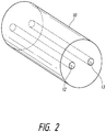
- the elongate instrument 10 may include a first channel 12 and a second channel 13 for holding or enclosing one more electrodes (e.g., as shown in Figure 2 ).
- a first electrode 14 may be positioned in the first channel 12 and a second electrode 15 maybe positioned in the second channel 13.
- the distal ends (or other portion) of the first and second electrodes 14,15 may be spaced apart such that when the electrodes are energized an electrical arc, plasma (ionized gas), or a plasma arc 18 may be formed between the electrodes, across the gap or space between the electrodes, creating or generating heat for ablating, desiccating, and/or killing tissue.
- the heat or plasma may create temperatures ranging from about 1000 to about 6000 degrees C or about 1500 to about 2000 degrees C.
- a heated steam may be created between the electrodes.
- the electrodes or wires may be connected to a generator (e.g., a radiofrequency (RF) generator) as a source of energy, e.g., high frequency energy or electricity.
- the plasma or plasma arc may be bright.
- second electrode 15 may extend along a longitudinal axis of the elongate instrument 10.
- Second electrode 15 may also include an arc 16 or turn, positioned at the distal end of the elongate instrument 10.
- the arc 16 may extend into a cap 17 or tip of the elongate instrument 10.
- the cap 17 or tip may be pointed or cone shaped and may include a conductive material.
- the energized second electrode 15 may transmit energy, e.g., heat or electrical current, through the conductive cap 17, to create a cutter or cutting element.
- the energized conductive cap 17 may be used to cut or create an opening through an airway wall and/or to cut through parenchyma or lung tissue when the conductive cap 17 is advanced through an airway wall and/or into parenchyma or lung tissue to access a target tissue.
- at least a portion of second electrode 15 may extend into a first channel 12 as well.
- the elongate instrument 10 may be in the form of a tube or cylinder made from glass, quartz, ceramic, or similar material or any material having a high melting point, able to withstand high temperatures.
- the tube or cylinder may include one or more channels, lumens or bores.
- One or more electrodes or wires may be positioned in the channels, lumens or bores of the tube or cylinder or otherwise within the elongate instrument.
- the electrodes may include a variety of materials. For example, tungsten, molybdenum, carbon, stainless steel or any other materials having similar properties or materials having a high melting point.
- the electrodes may have a variety of shapes or configurations, e.g., having straight or curved portions.
- the electrodes may be positioned in a channel that is either open to air or sealed. If sealed, the channel could be in a vacuum or filled with an inert gas. Alternatively, the channel may be melted around the electrodes, leaving no space at all.
- the elongate instrument, a tube or cylinder encapsulates the electrodes and traps any released vapor or gas emitted from the electrodes, e.g., tungsten vapor, to prevent or reduce the emission of vapor or gas into a patient's body.
- an elongate instrument may be with or without channels.
- the apparatus or electrodes for ablating tissue may be monopolar or bipolar.
- a ground plate or ground electrode may be utilized.
- the electrodes or wires may be affixed or melted to the elongate instrument to prevent the electrode wires from moving within the elongate instrument.
- a laser welder may be used to administer heat through a glass tube to melt the electrodes or wires to the glass tube.
- an apparatus for ablating tissue may include one or more electrodes or conductive wires or elements for generating heat between the electrodes or wires, and/or creating plasma or a plasma arc between the electrodes, to heat and ablate tissue.
- the electrodes or wires may or may not be encapsulated or positioned within an elongate instrument, e.g., a tube or cylinder.
- the electrodes may extend outside of an elongate instrument to form plasma or otherwise generate heat outside of the elongate instrument.
- the ends of electrodes utilized herein may be melted or shaped to provide an anode or cathode configuration. For this, each tip must be electrified and there may be no grounding plate. The grounding plate could be utilized for cutting a tract or path if the conductive wire or element most distal is one electrode and the grounding plate is the other electrode.
- a method for ablating a target tissue may include one or more of the following steps.
- the elongate instrument may be navigated within the subject.
- the elongate instrument may be advanced within a lumen of an airway in the lung.
- the elongate instrument may be advanced to, near on in proximity to the target tissue.
- One or more electrodes positioned within the elongate instrument may be energized and may transmit energy, e.g., heat or electrical current, through a conductive distal portion or cap of the elongate instrument, providing a cutting or piercing member or tip for cutting or piercing through tissue.
- energy e.g., heat or electrical current
- the energized distal portion or cap may be advanced through an airway wall, creating an opening or port through the airway wall and/or through or into the parenchyma or lung tissue.
- a non-energy based tunneling device such as a blunt dissection probe navigation and access system as described below and in US. Pat. Applications: US. Pat.
- 61/485,621, filed on May 13, 2011 ; 13/107,720, filed on May 13, 2011 ; 13/107,759, filed on May 13, 2011 ; and 61/563,369 filed November 23, 2011 may be employed to create the opening in the airway wall and/or the tunnel to access the target tissue.
- the elongate instrument and electrodes positioned therein may be advanced next to or near the target tissue or tumor or into the target tissue or tumor.
- the electrodes are energized (e.g., an electrical current flows through the electrode) such that a plasma or plasma arc is created between the electrodes.
- the electrodes and/or the plasma may generate heat to desiccate and kill the target tissue, e.g., the tumor or the blood vessels surrounding a target tissue or tumor, thereby cutting off the blood supply to the tumor.
- Ablation may be performed around the tumor to cut off its brood supply, e.g., in a couple of places around the tumor or all around the tumor.
- a crater may be ablated around the target tissue or tumor to kill the target tissue.
- a heated steam may be created between the electrodes.
- the elongate instrument and energized electrodes are allowed to remain in place within or near the target tissue for a certain time interval or until ablation of the target tissue is achieved. Indeed, the elongate instrument and electrodes may be positioned in or near the target tissue for an amount of time sufficient to allow heat to radiate from the electrodes and/or plasma arc, and through the tissue to desiccate, ablate vaporize and/or kill the target tissue. Radiation of heat through the target tissue may improve or increase as the tissue desiccates.
- the plasma arc may remain activated and may deliver heat to the target tissue for about 0 to 5 minutes.
- the plasma arc between the electrodes may generate heat until the electrodes are burned off and the plasma arc dissipates.
- the apparatus may then be disposed.
- the electricity provided to the electrodes may be pulsed to avoid burning off the electrodes or to cool the electrodes such that the electrodes may last for a longer duration.
- a fluid or gas may be circulated, e.g., on, in or around the elongate instrument, to provide active cooling of the electrodes.
- Various imaging technologies may be utilized to monitor the shrinkage of a tumor or target tissue as the tumor or other target tissue or the blood vessels supplying blood to the tumor are ablated using the apparatus and/or methods described herein.
- the light generated by the electrodes and/or the plasma or plasma arc may provide feedback, e.g. rapid feedback, regarding the location of the apparatus or the electrodes and plasma arc in the patient, e.g., when using visualization technology.
- the light may also be visible through the patient's skin, e.g., through the chest wall when the apparatus is positioned in the lung, allowing for localization of the apparatus by transillumination or direct visualization feedback.
- the apparatus and methods described herein may be utilized in a region of the patient's body where one or more or multiple tumors are present.
- tumors present in an upper lobe, lower lobe, and/or right or left side of a lung may be ablated using the apparatus and methods described herein.
- the apparatus may be advanced into tissue of a lung via an opening created through an airway wall, where the apparatus may be used to ablate multiple tumors and/or their corresponding blood vessels while the apparatus is positioned within the lung.
- the tumors or nodules may each be ablated, cooked or killed, e.g., in seconds to a minute or minutes, allowing multiple tumors or nodules to be ablated in a relatively short period of time.
- the apparatus and methods described herein may be used for performing ablation in various regions of a patient's body, e.g., the lung, liver, and/or brain.
- the energized electrodes or the plasma may create a vapor, e.g., a tungsten vapor when tungsten electrodes are utilized.
- a vapor e.g., a tungsten vapor when tungsten electrodes are utilized.
- the electrodes and plasma may be encapsulated within an elongate instrument, e.g., a glass tube (quartz glass or regular glass), which has a space for capturing the tungsten vapor.
- the glass tube may have dual channels in which electrodes may be positioned.
- the vapor may be captured within a channel and/or in a separate space or pocket within the elongate instrument or glass tube.
- a glass tube for encapsulating one or more electrodes or microelectrodes.
- the glass tube may have a diameter ranging from about 1.0 to about 2.0 millimeters, e.g., about 1.4 millimeters.
- the glass tube includes one or more channels or bores having a diameter similar in size or slightly larger than the size of the electrode or wire (e.g., tungsten) to be positioned therein and an outside diameter having a size sufficient to allow the apparatus to be fed down the working channel of common endoscopes or bronchoscopes.
- a method for creating a dual channel glass (or similar material) tube for encapsulating energized tungsten electrodes and the resulting tungsten vapor includes one or more of the following steps.
- a glass tube is heated such that the glass may melt around one or more tungsten electrodes.
- a balloon e.g., a nylon balloon
- the electrodes may be energized or activated, burning away the balloon which leaves a space between the electrodes that was previously occupied by the balloon.
- the energized electrodes create a plasma or plasma arc across that space.
- the glass tube surrounds, encapsulates or encloses the electrodes and the plasma arc and may capture any released gasses or vapor, e.g., tungsten vapor. Tubes for encapsulated other types of electrodes and their resulting vapor may also be created in accordance with the above manner.
- Electrodes encapsulated or enclosed in a glass tube or other elongate instrument may not oxidize or may experience minimal oxidation, allowing the electrodes to remain energized and/or burn for an extended amount of time, avoiding a rapid bum off.
- the encapsulated electrodes have strong conduction and generate heat sufficient for ablating tissue. Over time, the heat may melt the tube, and once the tube is melted around and/or between the electrodes to a point where the plasma arc and/or electrical arc and/or heat or heated steam is no longer generated, the apparatus may be disposed.
- an elongate instrument or glass tube may be reusable where the electrodes may be replaced after use with new electrodes.
- a tungsten wire may be bonded to molybdenum either mechanically or by laser wielding and a glass tube may be melted and/or bonded to the molybdenum for a stronger or improved bonding or connection between the glass and the electrodes.
- air/inert gas can be blown into the center of the glass tube or the formed pocket may later be filled with argon or other material.
- the tungsten can also be released, marking the area with a radio-opaque and MRI visible material.
- a nose cone or cap of various configurations or pointed tip may be fused or attached to the distal end of the elongate instrument over an electrode.
- This provides a cover or distal end to the apparatus or elongate instrument, which may have a variety of shapes or configurations depending on the particular use.
- the cap may conduct energy (e.g., electricity or heat) and act as a piercing member or cutter.
- the cap may have sharpened or pointed end to allow for mechanical piercing or cutting.
- glass utilized in any of the apparatus described herein may be metalilzed by inserting metal particles in the glass.
- a sheath e.g., a metal sheath
- a glass tube which provides a differing profile for temperature or delivery.
- a thick metal may maintain a high temperature for a longer duration.
- thermocouple or temperature gauge may be positioned in an elongate instrument, e.g., in a channel or bore within the elongate instrument.
- the thermocouple or temperature gauge may measure the temperature of the tissue and provide feedback regarding whether or not the ablation treatment is completed or not.
- a table may be utilized which provides parameters for how long tissue should be heated based on the size of a tumor or target tissue mass and/or distance of the device from the tumor.
- An MRI signature may also be used to determine the temperature of the tissue as it is heated.
- a reflector may be utilized to direct heat in a certain direction.
- a metalized reflector may be positioned on one side of the apparatus such that all of the heat is directed to the opposite side of the apparatus.
- the elongate instrument may be parabolic and/or radiopaque to facilitate proper orientation of the elongate instrument and the electrodes during use.
- the various ablating apparatus described herein may be guided or navigated to the target tissue or tumor and/or the target tissue or tumor may be located using one or more imaging technologies, such as, x-ray, CT, MRI, fluoroscopy
- various ablation methods and apparatus described herein may be guided to or may access a target tissue or tumor by being advanced into and through an airway, through an opening or extra anatomic opening created in an airway wall and to the target tissue or tumor beyond, at or near the created opening, where the target tissue is located in the lung, outside the lung or in another area of the body.
- methods or platforms for accessing target tissues e.g., diseased tissue, tumors, parenchyma or other tissues or structures
- target tissues e.g., diseased tissue, tumors, parenchyma or other tissues or structures
- the target tissue may be located outside of the airway in which the opening is created or beyond the airway wall, e.g., in the parenchyma of the lung.
- Access to the central airways may be achieved by using a standard bronchoscope or other scope or elongate instrument.
- a target site or point in a larger airway or central airway or smaller airway may be determined or selected, which may allow a straight or substantially straight tunnel, channel or path to be created leading directly to the target tissue.
- an opening is created through the airway wall at the target site on the wall by advancing a piercing member or needle to the target site and through the airway wall at the target site.
- the created opening may be dilated with a balloon catheter or other expandable device.
- a sheath or other elongate instrument may be fed through the hole or opening and into the lung tissue.
- the sheath may contain a dissecting catheter and the tip of the dissecting catheter may be sharp to tunnel through tissue or it may be blunt or rounded to allow it to tunnel without perforating blood vessels or other structures.
- the tip may tunnel or advance through the lung tissue in a substantially straight path where turns are minimized or eliminated.
- Imaging techniques may be utilized to guide the bronchoscope and piercing member and to guide the sheath, dissecting catheter, and/or ablation apparatus through the airway to the target site on the airway wall and/or to the target tissue for removal.
- Imaging techniques may include fluoroscopy, computed tomography, positron emission technology, magnetic resonance imaging, or ultrasound.
- the multiple steps of the above procedure i.e., creating an opening in the airway wall, going through the opening to dilate it and/or extending an instrument or apparatus through the opening to access a target tissue for ablation
- a multi purpose device e.g., a variation of an ablation apparatus as described herein, may create an opening with an energized piercing tip, and be advanced through the opening to dilate the opening and/or access a target tissue to perform ablation.
- the above procedure may be performed with more than one device, e.g., utilizing separate devices to create an opening, to dilate the opening and/or access a target tissue via the created opening with an ablation apparatus (as described herein) to ablate tissue.
- more than one device e.g., utilizing separate devices to create an opening, to dilate the opening and/or access a target tissue via the created opening with an ablation apparatus (as described herein) to ablate tissue.
- the various ablation methods or apparatus described herein may also be guided or navigated to or may access a target tissue or tumor using any of the various devices or methods for creating an extra-anatomic opening in an airway will and/or accessing tissue through an extra-anatomic opening through an airway wall as described in the hollowing: US. Pat. Applications: 61/485,621, filed on May 13, 2011 ; 13/107,720, filed on May 13, 2011 ; 13/107,759, filed on May 13, 2011 ; 61/563,369 filed November 23,2011 ; 11/538,950 filed October 5,2006 ; 12/939,968 filed November 4,2010 ; 12/939,961 filed November 4,2010 ; and 12/939,956 filed November 4, 2010 .
- any of the imaging technologies described above may be incorporated into an ablation apparatus or may be performed through an elongate instrument of the apparatus such that navigation or tracking, tissue cutting, and tissue ablation may be performed by a single device or, alternatively, by multiple devices provided via the elongate instrument or other instrument.
- any of the variations described herein may be used for cutting or ablating tissue in any region of the body, e.g., the lung, liver, or brain via various access points, utilizing minimally invasive or open surgery techniques.
Description
- This application is directed to methods and devices for ablating tissue. The procedures described herein may be performed in various regions of the body.
- Procedures have involved the insertion of an electrode directly into tumors, with a ground electrode positioned elsewhere on a patient or utilizing a bipolar electrode array. RF is sent through the electrode to generate heat in the tumor in an attempt to kill the tumor. The problem with these procedures is that generating heat around an electrode within a tumor may cause the tumor to desiccate. This increases impedance within the tumor and reduces current flow such that there isn't enough current flow to heat through and destroy the entire tumor. Multiple electrodes have been inserted into a tumor and the electrodes have been multiplexed in an attempt to energize each electrode and generate heat, however, this has shown to be complex and not very effective.
- Therefore, there remains a need for a more effective and efficient apparatus and method for ablating tissue in a minimally invasive manner.
-
US 5,919,191 discloses an apparatus for ablating tissue according to the pre-characterising portion ofclaim 1. - Various apparatus and methods for ablating tissue are described therein.
- According to the invention there is provided an apparatus for ablating tissue according to
claim 1. - A disclosed method for ablating tissue may include one or more of
the following steps. One or more electrodes, e.g., a first electrode and a second electrode, may be advanced to or near a target tissue in a subject. The electrodes may be energized
such that the electrodes create a plasma arc. The plasma arc generates heat which desiccates or ablates the target tissue. - In certain variations, various ablation methods and apparatus described herein
may be guided to or near a target tissue or may access a target tissue or tumor by being advanced into and through an airway, through an opening or extra-anatomic opening created in an airway wall and to or near the target tissue or tumor beyond, at, outside or near the created opening. In other variations, the methods and apparatus described herein may be utilized to perform ablation procedures in various regions of the body utilizing various access techniques. -
-
Figure 1 illustrates a variation of an apparatus for ablating tissue. -
Figure 2 illustrates a cross section of a variation of an elongate instrument of an apparatus for ablating tissue. - Various apparatus and methods for ablating tissue in a subject are described herein. Ablation may be performed on various types of tissues in various regions of the body, including, e.g., the lung. Various types of tissue may be ablated, including, e.g., diseased tissue or tumors. In certain variations, ablation may be performed
on blood vessels supplying blood to a tumor or other diseased or cancerous tissue. In certain variations, the procedures described herein may be performed through an opening, port or channel through an airway wall. - An apparatus for ablating tissue may include a heat source. The heat source may generate heat or heated steam to ablate a target tissue. A method for ablating tissue may include advancing a heat source to, near or in the proximity of a target tissue. The heat source may be left in position, next to or inside the target tissue where the heat source generates heat which desiccates, ablates, chars, vaporizes, and/or destroys the target tissue.
- Various heat sources may be utilized to ablate tissue. In one variation, an apparatus for ablating tissue may include one or more electrodes. For example, on apparatus may include two electrodes. The distal ends of the electrodes may be spaced apart such that when the electrodes are energized, a plasma or a plasma arc may be formed across the gap or space between the electrodes, creating or generating heat or steam for ablating tissue. The electrodes may be energized to generate heat to desiccate or kill target tissue and/or the blood vessels supplying blood to such tissue. The electrodes may be positioned within or may extend from an elongate instrument, such as a tube, shaft or other device.
-
Figure 1 shows one variation of an apparatus for ablating tissue. The apparatus may include anelongate instrument 10, e.g., a rod, tube shaft or sheath. Theelongate instrument 10 may include one or more lumens, bores or channels. For example, theelongate instrument 10 may include afirst channel 12 and asecond channel 13 for holding or enclosing one more electrodes (e.g., as shown inFigure 2 ). Afirst electrode 14 may be positioned in thefirst channel 12 and asecond electrode 15 maybe positioned in thesecond channel 13. The distal ends (or other portion) of the first andsecond electrodes plasma arc 18 may be formed between the electrodes, across the gap or space between the electrodes, creating or generating heat for ablating, desiccating, and/or killing tissue. The heat or plasma may create temperatures ranging from about 1000 to about 6000 degrees C or about 1500 to about 2000 degrees C. A heated steam may be created between the electrodes. The electrodes or wires may be connected to a generator (e.g., a radiofrequency (RF) generator) as a source of energy, e.g., high frequency energy or electricity. The plasma or plasma arc may be bright. - As shown in
Figure 1 ,second electrode 15 may extend along a longitudinal axis of theelongate instrument 10.Second electrode 15 may also include anarc 16 or turn, positioned at the distal end of theelongate instrument 10. Thearc 16 may extend into acap 17 or tip of theelongate instrument 10. Thecap 17 or tip may be pointed or cone shaped and may include a conductive material. The energizedsecond electrode 15 may transmit energy, e.g., heat or electrical current, through theconductive cap 17, to create a cutter or cutting element. For example, the energizedconductive cap 17 may be used to cut or create an opening through an airway wall and/or to cut through parenchyma or lung tissue when theconductive cap 17 is advanced through an airway wall and/or into parenchyma or lung tissue to access a target tissue. Optionally, at least a portion ofsecond electrode 15 may extend into afirst channel 12 as well. - The
elongate instrument 10 may be in the form of a tube or cylinder made from glass, quartz, ceramic, or similar material or any material having a high melting point, able to withstand high temperatures. The tube or cylinder may include one or more channels, lumens or bores. One or more electrodes or wires may be positioned in the channels, lumens or bores of the tube or cylinder or otherwise within the elongate instrument. The electrodes may include a variety of materials. For example, tungsten, molybdenum, carbon, stainless steel or any other materials having similar properties or materials having a high melting point. The electrodes may have a variety of shapes or configurations, e.g., having straight or curved portions. The electrodes may be positioned in a channel that is either open to air or sealed. If sealed, the channel could be in a vacuum or filled with an inert gas. Alternatively, the channel may be melted around the electrodes, leaving no space at all. The elongate instrument, a tube or cylinder encapsulates the electrodes and traps any released vapor or gas emitted from the electrodes, e.g., tungsten vapor, to prevent or reduce the emission of vapor or gas into a patient's body. In certain variations, an elongate instrument may be with or without channels. - The apparatus or electrodes for ablating tissue may be monopolar or bipolar.
For example, in certain variations, a ground plate or ground electrode may be utilized. The electrodes or wires may be affixed or melted to the elongate instrument to prevent the electrode wires from moving within the elongate instrument. For example, a laser welder may be used to administer heat through a glass tube to melt the electrodes or wires to the glass tube. - In certain variations, an apparatus for ablating tissue may include one or more electrodes or conductive wires or elements for generating heat between the electrodes or wires, and/or creating plasma or a plasma arc between the electrodes, to heat and ablate tissue. The electrodes or wires may or may not be encapsulated or positioned within an elongate instrument, e.g., a tube or cylinder. In certain variations, the electrodes may extend outside of an elongate instrument to form plasma or otherwise generate heat outside of the elongate instrument. Optionally, the ends of electrodes utilized herein may be melted or shaped to provide an anode or cathode configuration. For this, each tip must be electrified and there may be no grounding plate. The grounding plate could be utilized for cutting a tract or path if the conductive wire or element most distal is one electrode and the grounding plate is the other electrode.
- In one variation, a method for ablating a target tissue, e.g., a tumor, (lung or other), tissue surrounding a tumor, or blood vessels supplying blood to a tumor, may include one or more of the following steps. The elongate instrument may be navigated within the subject. For example, in the lung, the elongate instrument may be advanced within a lumen of an airway in the lung. The elongate instrument may be advanced to, near on in proximity to the target tissue. One or more electrodes positioned within the elongate instrument may be energized and may transmit energy, e.g., heat or electrical current, through a conductive distal portion or cap of the elongate instrument, providing a cutting or piercing member or tip for cutting or piercing through tissue. For example, for procedures in the lung, the energized distal portion or cap may be advanced through an airway wall, creating an opening or port through the airway wall and/or through or into the parenchyma or lung tissue. Alternately, a non-energy based tunneling device, such as a blunt dissection probe navigation and access system as described below and in
US. Pat. Applications: US. Pat. Applications: 61/485,621, filed on May 13, 2011 13/107,720, filed on May 13, 2011 13/107,759, filed on May 13, 2011 61/563,369 filed November 23, 2011 - The elongate instrument and electrodes positioned therein may be advanced next to or near the target tissue or tumor or into the target tissue or tumor. The electrodes are energized (e.g., an electrical current flows through the electrode) such that a plasma or plasma arc is created between the electrodes. The electrodes and/or the plasma may generate heat to desiccate and kill the target tissue, e.g., the tumor or the blood vessels surrounding a target tissue or tumor, thereby cutting off the blood supply to the tumor. Ablation may be performed around the tumor to cut off its brood supply, e.g., in a couple of places around the tumor or all around the tumor. A crater may be ablated around the target tissue or tumor to kill the target tissue. A heated steam may be created between the electrodes. The elongate instrument and energized electrodes are allowed to remain in place within or near the target tissue for a certain time interval or until ablation of the target tissue is achieved. Indeed, the elongate instrument and electrodes may be positioned in or near the target tissue for an amount of time sufficient to allow heat to radiate from the electrodes and/or plasma arc, and through the tissue to desiccate, ablate vaporize and/or kill the target tissue. Radiation of heat through the target tissue may improve or increase as the tissue desiccates.
- In one variation, the plasma arc may remain activated and may deliver heat
to the target tissue for about 0 to 5 minutes. In certain variations, the plasma arc between the electrodes may generate heat until the electrodes are burned off and the plasma arc dissipates. The apparatus may then be disposed. In certain variations, the electricity provided to the electrodes may be pulsed to avoid burning off the electrodes or to cool the electrodes such that the electrodes may last for a longer duration. In certain variations a fluid or gas may be circulated, e.g., on, in or around the elongate instrument, to provide active cooling of the electrodes. - Various imaging technologies (e.g. MRI, CT, PET, fluoroscopy, etc) may be utilized
to monitor the shrinkage of a tumor or target tissue as the tumor or other target tissue or the blood vessels supplying blood to the tumor are ablated using the apparatus and/or methods described herein. Alternatively, the light generated by the electrodes and/or the plasma or plasma arc may provide feedback, e.g. rapid feedback, regarding the location of the apparatus or the electrodes and plasma arc in the patient, e.g., when using visualization technology. The light may also be visible through the patient's skin, e.g., through the chest wall when the apparatus is positioned in the lung, allowing for localization of the apparatus by transillumination or direct visualization feedback. - In certain variations, the apparatus and methods described herein may be utilized in a region of the patient's body where one or more or multiple tumors are present. For example, tumors present in an upper lobe, lower lobe, and/or right or left side of a lung may be ablated using the apparatus and methods described herein. The apparatus may be advanced into tissue of a lung via an opening created through an airway wall, where the apparatus may be used to ablate multiple tumors and/or their corresponding blood vessels while the apparatus is positioned within the lung. The tumors or nodules may each be ablated, cooked or killed, e.g., in seconds to a minute or minutes, allowing multiple tumors or nodules to be ablated in a relatively short period of time. The apparatus and methods described herein may be used for performing ablation in various regions of a patient's body, e.g., the lung, liver, and/or brain.
- The energized electrodes or the plasma may create a vapor, e.g., a tungsten vapor when tungsten electrodes are utilized. Various devices for encapsulating the vapor such that the vapor is not released into a patient's body are provided. As described supra, the electrodes and plasma may be encapsulated within an elongate instrument, e.g., a glass tube (quartz glass or regular glass), which has a space for capturing the tungsten vapor. The glass tube may have dual channels in which electrodes may be positioned. The vapor may be captured within a channel and/or in a separate space or pocket within the elongate instrument or glass tube.
- In one variation, a glass tube is provided for encapsulating one or more electrodes or microelectrodes. The glass tube may have a diameter ranging from about 1.0 to about 2.0 millimeters, e.g., about 1.4 millimeters. The glass tube includes one or more channels or bores having a diameter similar in size or slightly larger than the size of the electrode or wire (e.g., tungsten) to be positioned therein and an outside diameter having a size sufficient to allow the apparatus to be fed down the working channel of common endoscopes or bronchoscopes.
- In one variation, a method for creating a dual channel glass (or similar material) tube for encapsulating energized tungsten electrodes and the resulting tungsten vapor includes one or more of the following steps. A glass tube is heated such that the glass may melt around one or more tungsten electrodes. A balloon (e.g., a nylon balloon) may be positioned between the electrodes, and may remain in between the electrodes as the glass is melted around the electrodes and the balloon, creating a bubble between the electrodes. Once the melting is complete and the tube having tungsten electrodes secured therein is complete, the electrodes may be energized or activated, burning away the balloon which leaves a space between the electrodes that was previously occupied by the balloon. The energized electrodes create a plasma or plasma arc across that space. The glass tube surrounds, encapsulates or encloses the electrodes and the plasma arc and may capture any released gasses or vapor, e.g., tungsten vapor. Tubes for encapsulated other types of electrodes and their resulting vapor may also be created in accordance with the above manner.
- Electrodes encapsulated or enclosed in a glass tube or other elongate instrument may not oxidize or may experience minimal oxidation, allowing the electrodes to remain energized and/or burn for an extended amount of time, avoiding a rapid bum off. The encapsulated electrodes have strong conduction and generate heat sufficient for ablating tissue. Over time, the heat may melt the tube, and once the tube is melted around and/or between the electrodes to a point where the plasma arc and/or electrical arc and/or heat or heated steam is no longer generated, the apparatus may be disposed. In other variations, an elongate instrument or glass tube may be reusable where the electrodes may be replaced after use with new electrodes.
- In another variation, a tungsten wire may be bonded to molybdenum either mechanically or by laser wielding and a glass tube may be melted and/or bonded to the molybdenum for a stronger or improved bonding or connection between the glass and the electrodes. During melting of the glass, air/inert gas can be blown into the center of the glass tube or the formed pocket may later be filled with argon or other material. The tungsten can also be released, marking the area with a radio-opaque and MRI visible material.
- In any of the above variations, a nose cone or cap of various configurations
or pointed tip may be fused or attached to the distal end of the elongate instrument over an electrode. This provides a cover or distal end to the apparatus or elongate instrument, which may have a variety of shapes or configurations depending on the particular use. The cap may conduct energy (e.g., electricity or heat) and act as a piercing member or cutter. Alternatively or in addition, the cap may have sharpened or pointed end to allow for mechanical piercing or cutting. - In certain variations, glass utilized in any of the apparatus described herein may be metalilzed by inserting metal particles in the glass. Optionally, a sheath (e.g., a metal sheath) may be positioned around a glass tube, which provides a differing profile for temperature or delivery. For example, a thick metal may maintain a high temperature for a longer duration.
- In any of the above variations, a thermocouple or temperature gauge may be positioned in an elongate instrument, e.g., in a channel or bore within the elongate instrument. The thermocouple or temperature gauge may measure the temperature of the tissue and provide feedback regarding whether or not the ablation treatment is completed or not. In certain variations, a table may be utilized which provides parameters for how long tissue should be heated based on the size of a tumor or target tissue mass and/or distance of the device from the tumor. An MRI signature may also be used to determine the temperature of the tissue as it is heated.
- In certain variations, a reflector may be utilized to direct heat in a certain direction. For example, a metalized reflector may be positioned on one side of the apparatus such that all of the heat is directed to the opposite side of the apparatus. In certain variations, the elongate instrument may be parabolic and/or radiopaque to facilitate proper orientation of the elongate instrument and the electrodes during use.
- The various ablating apparatus described herein, may be guided or navigated to the target tissue or tumor and/or the target tissue or tumor may be located using one or more imaging technologies, such as, x-ray, CT, MRI, fluoroscopy
- In certain variations, various ablation methods and apparatus described herein may be
guided to or may access a target tissue or tumor by being advanced into and through an airway, through an opening or extra anatomic opening created in an airway wall and to the target tissue or tumor beyond, at or near the created opening, where the target tissue is located in the lung, outside the lung or in another area of the body. - In certain variations, methods or platforms for accessing target tissues (e.g., diseased
tissue, tumors, parenchyma or other tissues or structures) in a lung or other area of the body, through an opening, extra-anatomic opening or port through the airway wall may be utilized to access a target tissue with any of the ablation apparatus or methods described herein. The target tissue may be located outside of the airway in which the opening is created or beyond the airway wall, e.g., in the parenchyma of the lung. - Access to the central airways may be achieved by using a standard bronchoscope or
other scope or elongate instrument. A target site or point in a larger airway or central airway or smaller airway may be determined or selected, which may allow a straight or substantially straight tunnel, channel or path to be created leading directly to the target tissue. Once the target site on the airway wall is located an opening is created through the airway wall at the target site on the wall by advancing a piercing member or needle to the target site and through the airway wall at the target site. The created opening may be dilated with a balloon catheter or other expandable device. - Once the opening has been dilated, a sheath or other elongate instrument may be fed
through the hole or opening and into the lung tissue. The sheath may contain a dissecting catheter and the tip of the dissecting catheter may be sharp to tunnel through tissue or it may be blunt or rounded to allow it to tunnel without perforating blood vessels or other structures. The tip may tunnel or advance through the lung tissue in a substantially straight path where turns are minimized or eliminated. Once the sheath and dissecting catheter are fed to or near the target tissue or tumor, the dissecting catheter may be removed, with the sheath remaining in position to be used to access the target tissue or tumor and to deliver any of the various ablation apparatus described herein to or near the target tissue or tumor to perform ablation. Various imaging techniques may be utilized to guide the bronchoscope and piercing member and to guide the sheath, dissecting catheter, and/or ablation apparatus through the airway to the target site on the airway wall and/or to the target tissue for removal. Imaging techniques may include fluoroscopy, computed tomography, positron emission technology, magnetic resonance imaging, or ultrasound. - In certain variations, the multiple steps of the above procedure, i.e., creating an opening in the airway wall, going through the opening to dilate it and/or extending an instrument or apparatus through the opening to access a target tissue for ablation, may be performed with a single device or with more than one device. For example, a multi purpose device, e.g., a variation of an ablation apparatus as described herein, may create an opening with an energized piercing tip, and be advanced through the opening to dilate the opening and/or access a target tissue to perform ablation. Alternatively, the above procedure may be performed with more than one device, e.g., utilizing separate devices to create an opening, to dilate the opening and/or access a target tissue via the created opening with an ablation apparatus (as described herein) to ablate tissue.
- The various ablation methods or apparatus described herein may also be guided or
navigated to or may access a target tissue or tumor using any of the various devices or methods for creating an extra-anatomic opening in an airway will and/or accessing tissue through an extra-anatomic opening through an airway wall as described in the hollowing:US. Pat. Applications: 61/485,621, filed on May 13, 2011 13/107,720, filed on May 13, 2011 13/107,759, filed on May 13, 2011 61/563,369 filed November 23,2011 11/538,950 filed October 5,2006 12/939,968 filed November 4,2010 12/939,961 filed November 4,2010 12/939,956 filed November 4, 2010 - In certain variations, any of the imaging technologies described above may be incorporated into an ablation apparatus or may be performed through an elongate instrument of the apparatus such that navigation or tracking, tissue cutting, and tissue ablation may be performed by a single device or, alternatively, by multiple devices provided via the elongate instrument or other instrument.
- Any of the variations described herein may used for cutting or ablating tissue
in any region of the body, e.g., the lung, liver, or brain via various access points, utilizing minimally invasive or open surgery techniques. - All publications, patent applications, patents, and other references mentioned herein are incorporated by reference in their entirety. To the extent there is a conflict in a meaning of a term, or otherwise, the present application will control. Although variations of the foregoing invention has been described in some detail by way of illustration and example for purposes of clarity of understanding, it will be readily apparent to those of ordinary skill in the art in light of the teachings of this invention that certain changes and modifications may be made thereto without departing from the scope of the appended claims. It is also contemplated that combinations of the above described embodiments/variations or combination of the specific aspects of the above described embodiments/variations are within the scope of this disclosure.
- Each of the individual variations described and illustrated herein has discrete components and features which may be readily separated from or combined with the features of any of the other variations. Modifications may be made to adapt a particular situation, material, composition of matter, process, process act(s) or step(s) to the objective(s), scope of the present invention.
- Methods recited herein may be carried out in any order of the recited events which is logically possible, as well as the recited order of events. Furthermore, where a range of values is provided, every intervening value between the upper and lower limit of that range and any other stated or intervening value in that stated range is encompassed within the invention. Also, any optional feature of the inventive variations described may be set forth and claimed independently, or in combination with any one or more of the features described herein.
- All existing subject matter mentioned herein (e.g., publications, patents, patent applications and hardware) is incorporated by reference herein in its entirety except insofar as the subject matter may conflict with that of the present invention (in which case what is present herein shall prevail). The referenced items are provided solely for their disclosure prior to the filing date of the present application. Nothing herein is to be construed as an admission that the present invention is not entitled to antedate such material by virtue of prior invention.
- Reference to a singular item, includes the possibility that there are plural of the same items present. More specifically, as used herein and in the appended claims, the singular forms "a," "an," "said" and "the" include plural referents unless the context clearly dictates otherwise. It is further noted that the claims may be drafted to exclude any optional element. As such, this statement is intended to serve as antecedent basis for use of such exclusive terminology as "solely," "only" and the like in connection with the recitation of claim elements, or use of a "negative" limitation. Unless defined otherwise, all technical and scientific terms used herein have the same meaning as commonly understood by one of ordinary skill in the art to which this invention belongs.
Claims (10)
- An apparatus for ablating tissue comprising:an elongate instrument (10);a first electrode (14) and a second electrode (15) positioned in the elongate instrument, wherein the electrodes are configured to create a plasma arc (18) for generating heat;characterized in that:the elongate instrument is configured to encapsulate the electrodes and trap vapor released from the electrodes.
- The apparatus of claim 1, wherein the elongate instrument comprises a tube having a first channel (12) and a second channel (13), wherein at least a portion of the first electrode is positioned within the first channel and at least a portion of the second electrode is positioned in the second channel.
- The apparatus of claim 1 or 2, wherein a space is provided between the electrode and a plasma arc is created in the space.
- The apparatus as claimed in any one of the preceding claims, wherein the electrodes are configured to burn off after a period of time.
- The apparatus as claimed in any one of the preceding claims, wherein the electrodes are made from tungsten or molybdenum.
- The apparatus as claimed in any one of the preceding claims, wherein the elongate instrument comprises a conductive cap (17) positioned at the distal end of the elongate instrument, wherein a portion of an electrode is positioned within the cap, such that the cap functions as an electrical cutter.
- The apparatus as claimed in any one of the preceding claims, further comprising an imaging mechanism for guiding or tracking the apparatus.
- The apparatus as claimed in any one of the preceding claims, wherein light generated by the plasma arc provides feedback regarding the localization of the plasma arc in the patient using.
- The apparatus as claimed in any one of the preceding claims, wherein the heat or plasma may create temperatures ranging from about 1000 to about 6000 degrees C.
- The apparatus as claimed in any one of the preceding claims, wherein the elongate instrument is configured to be advanced through an opening through an airway wall to position the plasma arc next to a target tissue or tumor in the lung.
Applications Claiming Priority (5)
| Application Number | Priority Date | Filing Date | Title |
|---|---|---|---|
| US201161485621P | 2011-05-13 | 2011-05-13 | |
| US201161486206P | 2011-05-13 | 2011-05-13 | |
| US13/107,720 US8709034B2 (en) | 2011-05-13 | 2011-05-13 | Methods and devices for diagnosing, monitoring, or treating medical conditions through an opening through an airway wall |
| US13/107,759 US20120289815A1 (en) | 2011-05-13 | 2011-05-13 | Methods and devices for diagnosing, monitoring, or treating medical conditions through an opening through an airway wall |
| PCT/US2012/037551 WO2012158530A1 (en) | 2011-05-13 | 2012-05-11 | Methods and devices for ablation of tissue |
Publications (3)
| Publication Number | Publication Date |
|---|---|
| EP2706940A1 EP2706940A1 (en) | 2014-03-19 |
| EP2706940A4 EP2706940A4 (en) | 2015-01-28 |
| EP2706940B1 true EP2706940B1 (en) | 2016-12-14 |
Family
ID=47177280
Family Applications (1)
| Application Number | Title | Priority Date | Filing Date |
|---|---|---|---|
| EP12786391.8A Active EP2706940B1 (en) | 2011-05-13 | 2012-05-11 | Methods and devices for ablation of tissue |
Country Status (4)
| Country | Link |
|---|---|
| US (2) | US9486229B2 (en) |
| EP (1) | EP2706940B1 (en) |
| JP (1) | JP2014521381A (en) |
| WO (2) | WO2012158553A2 (en) |
Families Citing this family (22)
| Publication number | Priority date | Publication date | Assignee | Title |
|---|---|---|---|---|
| US20110306997A9 (en) * | 2002-02-21 | 2011-12-15 | Roschak Edmund J | Devices for creating passages and sensing for blood vessels |
| US8308682B2 (en) | 2003-07-18 | 2012-11-13 | Broncus Medical Inc. | Devices for maintaining patency of surgically created channels in tissue |
| US8409167B2 (en) | 2004-07-19 | 2013-04-02 | Broncus Medical Inc | Devices for delivering substances through an extra-anatomic opening created in an airway |
| JP2014521381A (en) | 2011-05-13 | 2014-08-28 | ブロンカス テクノロジーズ, インコーポレイテッド | Methods and devices for tissue ablation |
| US8709034B2 (en) | 2011-05-13 | 2014-04-29 | Broncus Medical Inc. | Methods and devices for diagnosing, monitoring, or treating medical conditions through an opening through an airway wall |
| WO2013078235A1 (en) | 2011-11-23 | 2013-05-30 | Broncus Medical Inc | Methods and devices for diagnosing, monitoring, or treating medical conditions through an opening through an airway wall |
| KR101356607B1 (en) * | 2012-06-26 | 2014-02-03 | 신경민 | High-frequency treatment device |
| US9788858B2 (en) | 2013-04-15 | 2017-10-17 | Transseptal Solutions Ltd. | Fossa ovalis penetration using probing elements |
| US10772678B2 (en) | 2013-09-30 | 2020-09-15 | Michael D. Laufer | Methods and devices for diastolic assist |
| CA2925933A1 (en) | 2013-09-30 | 2015-04-02 | Cordynamix, Inc. | Methods and devices for diastolic assist |
| KR20240013275A (en) | 2014-07-22 | 2024-01-30 | 엑시미스 서지컬 인코포레이티드 | Large volume tissue reduction and removal system and method |
| EP3206603B1 (en) | 2014-10-14 | 2019-10-02 | Transseptal Solutions Ltd. | Fossa ovalis penetration apparatus |
| EP3349677A1 (en) | 2015-09-17 | 2018-07-25 | Eximis Surgical LLC | Electrosurgical device and methods |
| US10398503B2 (en) | 2015-10-14 | 2019-09-03 | Transseptal Soulutions Ltd. | Fossa ovalis penetration |
| CN105748111A (en) * | 2016-03-09 | 2016-07-13 | 中国人民解放军成都军区总医院 | Rib fretsaw locator for thoracoscope |
| CN106388898B (en) * | 2016-03-09 | 2019-02-12 | 中国人民解放军成都军区总医院 | A kind of thoracoscope rib cage scroll saw guiding positioning suit |
| US11832877B2 (en) | 2017-04-03 | 2023-12-05 | Broncus Medical Inc. | Electrosurgical access sheath |
| CN109464186B (en) | 2017-09-08 | 2023-12-22 | 泽丹医疗股份有限公司 | Device and method for treating lung tumors |
| CN111989061A (en) | 2018-04-13 | 2020-11-24 | 卡尔史托斯两合公司 | Guidance system, method and device thereof |
| EP3931221A1 (en) | 2019-03-01 | 2022-01-05 | Rampart Health, L.L.C. | Pharmaceutical composition combining immunologic and chemotherapeutic method for the treatment of cancer |
| US10980402B2 (en) | 2019-04-03 | 2021-04-20 | Olympus Corporation | Diathermic endotherapeutic device |
| WO2022174064A2 (en) | 2021-02-12 | 2022-08-18 | Rampart Health, L.L.C. | Therapeutic composition and method combining multiplex immunotherapy with cancer vaccine for the treatment of cancer |
Family Cites Families (631)
| Publication number | Priority date | Publication date | Assignee | Title |
|---|---|---|---|---|
| US2127903A (en) | 1936-05-05 | 1938-08-23 | Davis & Geck Inc | Tube for surgical purposes and method of preparing and using the same |
| US3174851A (en) | 1961-12-01 | 1965-03-23 | William J Buehler | Nickel-base alloys |
| US3406685A (en) | 1963-07-23 | 1968-10-22 | Becton Dickinson Co | Catheter needle and method for its manufacture |
| US3433226A (en) | 1965-07-21 | 1969-03-18 | Aeroprojects Inc | Vibratory catheterization apparatus and method of using |
| US3351463A (en) | 1965-08-20 | 1967-11-07 | Alexander G Rozner | High strength nickel-base alloys |
| US3490457A (en) | 1967-02-06 | 1970-01-20 | Roy A Petersen | Catheter |
| US3617060A (en) | 1967-04-10 | 1971-11-02 | Warren Iezzi | Pneumothorox-inducing hunting arrow |
| US3556079A (en) | 1967-05-16 | 1971-01-19 | Haruo Omizo | Method of puncturing a medical instrument under guidance of ultrasound |
| US3565062A (en) | 1968-06-13 | 1971-02-23 | Ultrasonic Systems | Ultrasonic method and apparatus for removing cholesterol and other deposits from blood vessels and the like |
| US3753700A (en) | 1970-07-02 | 1973-08-21 | Raychem Corp | Heat recoverable alloy |
| US3707151A (en) | 1971-02-16 | 1972-12-26 | Richard Robert Jackson | Self-inflating endotracheal tube |
| US3779234A (en) | 1971-06-30 | 1973-12-18 | Intersc Res Inst | Ultrasonic catheter with rotating transducers |
| DE2219790C3 (en) | 1972-04-22 | 1974-11-07 | R Pohlman | Device for generating brittle fractures in hard stones |
| US3874388A (en) | 1973-02-12 | 1975-04-01 | Ochsner Med Found Alton | Shunt defect closure system |
| US3828790A (en) * | 1973-02-28 | 1974-08-13 | American Cystoscope Makers Inc | Surgical snare |
| DK131541B (en) | 1973-09-03 | 1975-08-04 | Akad Tekn Videnskaber | Prostate rectoscope. |
| US3889688A (en) | 1973-12-19 | 1975-06-17 | Precha Eamkaow | Tracheostomy tube with novel retaining means |
| US4281669A (en) | 1975-05-09 | 1981-08-04 | Macgregor David C | Pacemaker electrode with porous system |
| US4249539A (en) | 1979-02-09 | 1981-02-10 | Technicare Corporation | Ultrasound needle tip localization system |
| DE2911258C2 (en) | 1979-03-22 | 1982-09-23 | Chmiel, Horst, Prof. Dr.-Ing., 7250 Leonberg | Device for the non-invasive measurement of blood flow velocity using the ultrasonic Doppler effect method |
| US4249541A (en) | 1979-04-26 | 1981-02-10 | David S. Pratt | Biopsy device |
| US4319580A (en) | 1979-08-28 | 1982-03-16 | The Board Of Regents Of The University Of Washington | Method for detecting air emboli in the blood in an intracorporeal blood vessel |
| US4324235A (en) | 1980-03-24 | 1982-04-13 | Beran Anthony V | Endotracheal tube |
| US4469142A (en) | 1980-09-30 | 1984-09-04 | Scapa Inc. | Papermakers belt having smooth surfaces and enlarged seam loops |
| US4332254A (en) | 1980-11-17 | 1982-06-01 | Advanced Catheter Systems, Inc. | System for filling and inflating and deflating a vascular dilating cathether assembly |
| US4534761A (en) | 1981-08-14 | 1985-08-13 | Bentley Laboratories, Inc. | Implant device |
| US4407294A (en) | 1982-01-07 | 1983-10-04 | Technicare Corporation | Ultrasound tissue probe localization system |
| US4431006A (en) | 1982-01-07 | 1984-02-14 | Technicare Corporation | Passive ultrasound needle probe locator |
| US4493320A (en) | 1982-04-02 | 1985-01-15 | Treat Michael R | Bipolar electrocautery surgical snare |
| SE445884B (en) | 1982-04-30 | 1986-07-28 | Medinvent Sa | DEVICE FOR IMPLANTATION OF A RODFORM PROTECTION |
| US5370675A (en) | 1992-08-12 | 1994-12-06 | Vidamed, Inc. | Medical probe device and method |
| US4538606A (en) | 1982-12-10 | 1985-09-03 | Whited Robert E | Endotracheal tube |
| US4582067A (en) | 1983-02-14 | 1986-04-15 | Washington Research Foundation | Method for endoscopic blood flow detection by the use of ultrasonic energy |
| US4770185A (en) | 1983-02-14 | 1988-09-13 | The Board Of Regents Of The University Of Washington | Method and apparatus for endoscopic blood flow detection by the use of ultrasonic energy |
| US4503569A (en) | 1983-03-03 | 1985-03-12 | Dotter Charles T | Transluminally placed expandable graft prosthesis |
| IL68115A (en) | 1983-03-14 | 1987-03-31 | Rosenberg Lior | Fluid flow detector particularly useful for microvascular monitoring |
| CA1230278A (en) | 1983-04-13 | 1987-12-15 | Peter Persson | Instrument for the treatment of respiratory obstruction |
| US4773413A (en) | 1983-06-13 | 1988-09-27 | Trimedyne Laser Systems, Inc. | Localized heat applying medical device |
| EP0148250A1 (en) | 1983-07-06 | 1985-07-17 | STASZ, Peter | Electro cautery surgical blade |
| US4702252A (en) | 1983-10-13 | 1987-10-27 | Smiths Industries Public Limited Company | Catheters |
| US4687482A (en) | 1984-04-27 | 1987-08-18 | Scripps Clinic And Research Foundation | Vascular prosthesis |
| US4682596A (en) | 1984-05-22 | 1987-07-28 | Cordis Corporation | Electrosurgical catheter and method for vascular applications |
| US4583969A (en) | 1984-06-26 | 1986-04-22 | Mortensen J D | Apparatus and method for in vivo extrapulmonary blood gas exchange |
| EP0177124A3 (en) | 1984-07-18 | 1987-01-21 | Sumitomo Electric Industries Limited | Catheter |
| CA1245931A (en) | 1984-09-21 | 1988-12-06 | Sophia Pesotchinsky | Positionable tissue interfacing device for the management of percutaneous conduits |
| IT1199942B (en) | 1985-02-07 | 1989-01-05 | Biotronix Srl | DETECTION INSTRUMENT OF THE CIRCULAR SECTION EQUIVALENT IN THE AREA TO THE SECTION OF A BLOOD VESSEL |
| US4658817A (en) | 1985-04-01 | 1987-04-21 | Children's Hospital Medical Center | Method and apparatus for transmyocardial revascularization using a laser |
| US4767627A (en) | 1985-05-29 | 1988-08-30 | Merck & Co., Inc. | Drug delivery device which can be retained in the stomach for a controlled period of time |
| US4892098A (en) | 1985-06-26 | 1990-01-09 | Sauer Jude S | Tubular tissue welding device without moving parts |
| US4750488A (en) | 1986-05-19 | 1988-06-14 | Sonomed Technology, Inc. | Vibration apparatus preferably for endoscopic ultrasonic aspirator |
| US4750902A (en) | 1985-08-28 | 1988-06-14 | Sonomed Technology, Inc. | Endoscopic ultrasonic aspirators |
| US4706689A (en) | 1985-10-30 | 1987-11-17 | Daniel Man | Implantable homing device |
| JPH0824678B2 (en) | 1985-11-02 | 1996-03-13 | 株式会社東芝 | Ultrasonic diagnostic equipment |
| US5102417A (en) | 1985-11-07 | 1992-04-07 | Expandable Grafts Partnership | Expandable intraluminal graft, and method and apparatus for implanting an expandable intraluminal graft |
| US4921483A (en) | 1985-12-19 | 1990-05-01 | Leocor, Inc. | Angioplasty catheter |
| US4807634A (en) | 1986-02-04 | 1989-02-28 | Kabushiki Kaisha Toshiba | Mechanical type ultrasonic scanner |
| FR2595860A1 (en) | 1986-03-17 | 1987-09-18 | Kodak Pathe | COMPENSATION FILTER FOR RADIOGRAPHY |
| US4753236A (en) | 1986-04-08 | 1988-06-28 | Healey Maureen A | Temporary anastomotic device |
| SE453258B (en) | 1986-04-21 | 1988-01-25 | Medinvent Sa | ELASTIC, SELF-EXPANDING PROTEST AND PROCEDURE FOR ITS MANUFACTURING |
| US5002058A (en) | 1986-04-25 | 1991-03-26 | Intra-Sonix, Inc. | Ultrasonic transducer |
| ES8800028A1 (en) | 1986-06-25 | 1987-11-01 | Fuchelman Sa | Contour type electrosurgical dispersive electrode. |
| US4769031A (en) | 1986-06-25 | 1988-09-06 | Mcgough Edwin C | Ventricular access device and method |
| US4771788A (en) | 1986-07-18 | 1988-09-20 | Pfizer Hospital Products Group, Inc. | Doppler tip wire guide |
| WO1988001218A1 (en) * | 1986-08-11 | 1988-02-25 | 2-I Moskovsky Gosudarstvenny Meditsinsky Institut | Device for plasma-arc cutting of biological tissues |
| US4887606A (en) | 1986-09-18 | 1989-12-19 | Yock Paul G | Apparatus for use in cannulation of blood vessels |
| US5263992A (en) | 1986-10-17 | 1993-11-23 | Bio-Metric Systems, Inc. | Biocompatible device with covalently bonded biocompatible agent |
| JPH0763489B2 (en) | 1986-10-31 | 1995-07-12 | 宇部興産株式会社 | Medical tube |
| US4757821A (en) | 1986-11-12 | 1988-07-19 | Corazonix Corporation | Omnidirectional ultrasonic probe |
| US4808153A (en) | 1986-11-17 | 1989-02-28 | Ultramed Corporation | Device for removing plaque from arteries |
| US4781676A (en) | 1987-02-20 | 1988-11-01 | Air Products And Chemicals, Inc. | Interstitial administration of perfluorochemical emulsions for reoxygenation of hypoxic tumor cells |
| US4967753A (en) | 1987-04-10 | 1990-11-06 | Cardiometrics, Inc. | Apparatus, system and method for measuring spatial average velocity and/or volumetric flow of blood in a vessel |
| US4869268A (en) | 1987-05-14 | 1989-09-26 | Inbae Yoon | Multi-functional instruments and stretchable ligating and occluding devices |
| US4795465A (en) | 1987-05-14 | 1989-01-03 | Hood Laboratories | Tracheobronchial stent |
| US4802476A (en) | 1987-06-01 | 1989-02-07 | Everest Medical Corporation | Electro-surgical instrument |
| DE3719250A1 (en) | 1987-06-10 | 1988-12-22 | Kellner Hans Joerg Dr Med | ENDOSCOPE |
| US4917097A (en) | 1987-10-27 | 1990-04-17 | Endosonics Corporation | Apparatus and method for imaging small cavities |
| GB2212267B (en) | 1987-11-11 | 1992-07-29 | Circulation Res Ltd | Methods and apparatus for the examination and treatment of internal organs |
| US4870953A (en) | 1987-11-13 | 1989-10-03 | Donmicheal T Anthony | Intravascular ultrasonic catheter/probe and method for treating intravascular blockage |
| DE3738797A1 (en) | 1987-11-14 | 1989-05-24 | Rentrop Hubbert & Wagner | LINEAR ADJUSTABLE FORCE TRANSMISSION ELEMENT WITH CONTINUOUS, INACCESSIVE SENSITIVITY BLOCKING |
| CA1325458C (en) | 1988-01-22 | 1993-12-21 | Jonathan Bernstein | Vivo ultrasonic system for angioplasty and ultrasonic contrast imaging |
| US4899757A (en) | 1988-02-22 | 1990-02-13 | Intertherapy, Inc. | Ultrasound imaging probe with zero dead space |
| US4834102A (en) | 1988-02-25 | 1989-05-30 | Jack Schwarzchild | Endoscope for transesophageal echocardiography |
| US4977898A (en) | 1988-02-25 | 1990-12-18 | Hoffrel Instruments, Inc. | Miniaturized encapsulated ultrasonic transducer |
| US5372138A (en) | 1988-03-21 | 1994-12-13 | Boston Scientific Corporation | Acousting imaging catheters and the like |
| US5368035A (en) | 1988-03-21 | 1994-11-29 | Boston Scientific Corporation | Ultrasound imaging guidewire |
| US5588432A (en) | 1988-03-21 | 1996-12-31 | Boston Scientific Corporation | Catheters for imaging, sensing electrical potentials, and ablating tissue |
| US4924863A (en) | 1988-05-04 | 1990-05-15 | Mmtc, Inc. | Angioplastic method for removing plaque from a vas |
| US5002772A (en) | 1988-05-31 | 1991-03-26 | Pfizer Inc. | Gastric retention system for controlled drug release |
| JPH01310648A (en) | 1988-06-08 | 1989-12-14 | Toshiba Corp | Ultrasonic blood circulation imaging device |
| EP0347098B1 (en) | 1988-06-13 | 1996-02-28 | Samuel Shiber | Atherectomy system with a guide-wire |
| US5514091A (en) | 1988-07-22 | 1996-05-07 | Yoon; Inbae | Expandable multifunctional manipulating instruments for various medical procedures |
| US4920954A (en) | 1988-08-05 | 1990-05-01 | Sonic Needle Corporation | Ultrasonic device for applying cavitation forces |
| US5575815A (en) | 1988-08-24 | 1996-11-19 | Endoluminal Therapeutics, Inc. | Local polymeric gel therapy |
| US4955377A (en) | 1988-10-28 | 1990-09-11 | Lennox Charles D | Device and method for heating tissue in a patient's body |
| AU4945490A (en) | 1989-01-06 | 1990-08-01 | Angioplasty Systems Inc. | Electrosurgical catheter for resolving atherosclerotic plaque |
| US4966162A (en) | 1989-01-25 | 1990-10-30 | Wang Ko P | Flexible encoscope assembly |
| US5054483A (en) | 1989-03-06 | 1991-10-08 | Hood Laboratories | Tracheal cannulas and stents |
| US5425739A (en) | 1989-03-09 | 1995-06-20 | Avatar Design And Development, Inc. | Anastomosis stent and stent selection system |
| US4930525A (en) | 1989-03-28 | 1990-06-05 | Palestrant Aubrey M | Method for performing C.T. guided drainage and biopsy procedures |
| US4936281A (en) | 1989-04-13 | 1990-06-26 | Everest Medical Corporation | Ultrasonically enhanced RF ablation catheter |
| JP2754493B2 (en) | 1989-05-20 | 1998-05-20 | 富士通株式会社 | Blood flow visualization method |
| ATE134492T1 (en) | 1989-06-01 | 1996-03-15 | Schneider Europ Ag | CATHETER ARRANGEMENT WITH A GUIDE WIRE AND METHOD FOR PRODUCING SUCH A GUIDE WIRE |
| US4991602A (en) | 1989-06-27 | 1991-02-12 | Flexmedics Corporation | Flexible guide wire with safety tip |
| US4973301A (en) | 1989-07-11 | 1990-11-27 | Israel Nissenkorn | Catheter and method of using same |
| US4976690A (en) | 1989-08-10 | 1990-12-11 | Scimed Life Systems, Inc. | Variable stiffness angioplasty catheter |
| US6344053B1 (en) | 1993-12-22 | 2002-02-05 | Medtronic Ave, Inc. | Endovascular support device and method |
| US5220924A (en) | 1989-09-28 | 1993-06-22 | Frazin Leon J | Doppler-guided retrograde catheterization using transducer equipped guide wire |
| US5047026A (en) | 1989-09-29 | 1991-09-10 | Everest Medical Corporation | Electrosurgical implement for tunneling through tissue |
| US5240003A (en) | 1989-10-16 | 1993-08-31 | Du-Med B.V. | Ultrasonic instrument with a micro motor having stator coils on a flexible circuit board |
| US5030201A (en) | 1989-11-24 | 1991-07-09 | Aubrey Palestrant | Expandable atherectomy catheter device |
| GB8928533D0 (en) | 1989-12-18 | 1990-02-21 | Lesny Jan | Ultrasonic instrument |
| IL93141A0 (en) | 1990-01-23 | 1990-11-05 | Urcan Medical Ltd | Ultrasonic recanalization system |
| US5069664A (en) | 1990-01-25 | 1991-12-03 | Inter Therapy, Inc. | Intravascular ultrasonic angioplasty probe |
| JP2791165B2 (en) | 1990-02-07 | 1998-08-27 | 株式会社東芝 | Intravascular ultrasound probe |
| US5148809A (en) | 1990-02-28 | 1992-09-22 | Asgard Medical Systems, Inc. | Method and apparatus for detecting blood vessels and displaying an enhanced video image from an ultrasound scan |
| US5545208A (en) | 1990-02-28 | 1996-08-13 | Medtronic, Inc. | Intralumenal drug eluting prosthesis |
| US5413601A (en) | 1990-03-26 | 1995-05-09 | Keshelava; Viktor V. | Tubular organ prosthesis |
| US5131394A (en) | 1990-03-28 | 1992-07-21 | Gehlbach Steve M | Ultrasonic guided needle |
| US5123917A (en) | 1990-04-27 | 1992-06-23 | Lee Peter Y | Expandable intraluminal vascular graft |
| US5148838A (en) | 1990-06-06 | 1992-09-22 | Asten Group, Inc. | Papermakers fabric with orthogonal machine direction yarn seaming loops |
| US5064435A (en) | 1990-06-28 | 1991-11-12 | Schneider (Usa) Inc. | Self-expanding prosthesis having stable axial length |
| US5201741A (en) | 1990-07-24 | 1993-04-13 | Andrew Surgical, Inc. | Surgical snare with shape memory effect wire |
| NL9001755A (en) | 1990-08-02 | 1992-03-02 | Optische Ind De Oude Delft Nv | ENDOSCOPIC SCANNER. |
| US5100423A (en) | 1990-08-21 | 1992-03-31 | Medical Engineering & Development Institute, Inc. | Ablation catheter |
| US5282799A (en) | 1990-08-24 | 1994-02-01 | Everest Medical Corporation | Bipolar electrosurgical scalpel with paired loop electrodes |
| US5234447A (en) | 1990-08-28 | 1993-08-10 | Robert L. Kaster | Side-to-end vascular anastomotic staple apparatus |
| EP0474957A3 (en) | 1990-09-11 | 1992-06-24 | Bozidar Ferek-Petric | Ultrasonic doppler synchronized cardiac electrotherapy device |
| US5125926A (en) | 1990-09-24 | 1992-06-30 | Laser Engineering, Inc. | Heart-synchronized pulsed laser system |
| DK0480667T3 (en) | 1990-10-09 | 1996-06-10 | Cook Inc | Percutaneous stent construction |
| JPH0717314Y2 (en) | 1990-10-18 | 1995-04-26 | ソン ホーヨン | Self-expanding intravascular stent |
| US5190528A (en) | 1990-10-19 | 1993-03-02 | Boston University | Percutaneous transseptal left atrial cannulation system |
| US5254112A (en) | 1990-10-29 | 1993-10-19 | C. R. Bard, Inc. | Device for use in laser angioplasty |
| US5527292A (en) | 1990-10-29 | 1996-06-18 | Scimed Life Systems, Inc. | Intravascular device for coronary heart treatment |
| US5389096A (en) | 1990-12-18 | 1995-02-14 | Advanced Cardiovascular Systems | System and method for percutaneous myocardial revascularization |
| JP2555298B2 (en) | 1990-11-10 | 1996-11-20 | テルモ株式会社 | CATHETER BALLOON, CATHETER BALLOON MANUFACTURING METHOD, AND BALLOON CATHETER |
| US5380316A (en) | 1990-12-18 | 1995-01-10 | Advanced Cardiovascular Systems, Inc. | Method for intra-operative myocardial device revascularization |
| US5145684A (en) | 1991-01-25 | 1992-09-08 | Sterling Drug Inc. | Surface modified drug nanoparticles |
| ATE183935T1 (en) | 1991-02-13 | 1999-09-15 | Applied Med Resources | SURGICAL TROCAR |
| US5152754A (en) | 1991-02-15 | 1992-10-06 | Minnesota Mining And Manufacturing Company | Trocar |
| US5762638A (en) | 1991-02-27 | 1998-06-09 | Shikani; Alain H. | Anti-infective and anti-inflammatory releasing systems for medical devices |
| US5201316A (en) | 1991-03-18 | 1993-04-13 | Cardiovascular Imaging Systems, Inc. | Guide wire receptacle for catheters having rigid housings |
| US5554118A (en) | 1991-05-24 | 1996-09-10 | Jang; G. David | Universal mode vascular catheter system |
| US5261409A (en) | 1991-05-27 | 1993-11-16 | Sulzer Brothers Limited | Puncturing device for blood vessels |
| US5304200A (en) | 1991-05-29 | 1994-04-19 | Cordis Corporation | Welded radially expandable endoprosthesis and the like |
| US5452733A (en) | 1993-02-22 | 1995-09-26 | Stanford Surgical Technologies, Inc. | Methods for performing thoracoscopic coronary artery bypass |
| US5795325A (en) | 1991-07-16 | 1998-08-18 | Heartport, Inc. | Methods and apparatus for anchoring an occluding member |
| US5155435A (en) | 1991-08-08 | 1992-10-13 | The Regents Of The University Of California | Method and apparatus for performing interventional medical procedures using MR imaging of interventional device superimposed with ghost patient image |
| US5377682A (en) | 1991-09-05 | 1995-01-03 | Matsushita Electric Industrial Co., Ltd. | Ultrasonic probe for transmission and reception of ultrasonic wave and ultrasonic diagnostic apparatus including ultrasonic probe |
| US5302168A (en) | 1991-09-05 | 1994-04-12 | Hess Robert L | Method and apparatus for restenosis treatment |
| US5443498A (en) | 1991-10-01 | 1995-08-22 | Cook Incorporated | Vascular stent and method of making and implanting a vacsular stent |
| US5500013A (en) | 1991-10-04 | 1996-03-19 | Scimed Life Systems, Inc. | Biodegradable drug delivery vascular stent |
| US5697281A (en) | 1991-10-09 | 1997-12-16 | Arthrocare Corporation | System and method for electrosurgical cutting and ablation |
| US5366504A (en) | 1992-05-20 | 1994-11-22 | Boston Scientific Corporation | Tubular medical prosthesis |
| US5876445A (en) | 1991-10-09 | 1999-03-02 | Boston Scientific Corporation | Medical stents for body lumens exhibiting peristaltic motion |
| US5354309A (en) | 1991-10-11 | 1994-10-11 | Angiomed Ag | Apparatus for widening a stenosis in a body cavity |
| US7549424B2 (en) | 1991-10-18 | 2009-06-23 | Pro Surg, Inc. | Method and apparatus for tissue treatment with laser and electromagnetic radiation |
| US5269326A (en) | 1991-10-24 | 1993-12-14 | Georgetown University | Method for transvenously accessing the pericardial space via the right auricle for medical procedures |
| CA2079417C (en) | 1991-10-28 | 2003-01-07 | Lilip Lau | Expandable stents and method of making same |
| US5997547A (en) * | 1991-11-05 | 1999-12-07 | Nakao; Naomi L. | Surgical retrieval assembly and associated method |
| US5246014A (en) | 1991-11-08 | 1993-09-21 | Medtronic, Inc. | Implantable lead system |
| DE69226371T2 (en) | 1991-11-08 | 1999-04-22 | Baxter Int | TRANSPORT CATHETER AND ULTRASONIC PROBE FOR USE WITH THE SAME |
| US5704361A (en) | 1991-11-08 | 1998-01-06 | Mayo Foundation For Medical Education And Research | Volumetric image ultrasound transducer underfluid catheter system |
| US5325860A (en) | 1991-11-08 | 1994-07-05 | Mayo Foundation For Medical Education And Research | Ultrasonic and interventional catheter and method |
| US5259385A (en) | 1991-12-23 | 1993-11-09 | Advanced Cardiovascular Systems, Inc. | Apparatus for the cannulation of blood vessels |
| US5683366A (en) | 1992-01-07 | 1997-11-04 | Arthrocare Corporation | System and method for electrosurgical tissue canalization |
| US5300119A (en) | 1992-01-10 | 1994-04-05 | Hansa Medical Products, Inc. | Delivery system |
| US5246011A (en) | 1992-01-30 | 1993-09-21 | Caillouette James C | Fine needle aspiration syringe |
| GB2263974B (en) | 1992-01-30 | 1995-11-08 | Intravascular Res Ltd | Ultrasound imaging and catheters for use therein |
| US5209721A (en) | 1992-01-31 | 1993-05-11 | Wilk Peter J | Laparoscopic surgical device and related method |
| JP2727536B2 (en) | 1992-02-20 | 1998-03-11 | 富士写真光機株式会社 | In-vivo diagnostic device |
| US5257990A (en) | 1992-02-24 | 1993-11-02 | Kensey Nash Corporation | Electrosurgical catheter instrument with impacting working head and method of use |
| US5313950A (en) | 1992-02-25 | 1994-05-24 | Fujitsu Limited | Ultrasonic probe |
| US5509900A (en) | 1992-03-02 | 1996-04-23 | Kirkman; Thomas R. | Apparatus and method for retaining a catheter in a blood vessel in a fixed position |
| US5226421A (en) | 1992-03-06 | 1993-07-13 | Cardiometrics, Inc. | Doppler elongate flexible member having an inflatable balloon mounted thereon |
| FR2688401B1 (en) | 1992-03-12 | 1998-02-27 | Thierry Richard | EXPANDABLE STENT FOR HUMAN OR ANIMAL TUBULAR MEMBER, AND IMPLEMENTATION TOOL. |
| US5318564A (en) | 1992-05-01 | 1994-06-07 | Hemostatic Surgery Corporation | Bipolar surgical snare and methods of use |
| US5178635A (en) | 1992-05-04 | 1993-01-12 | Allergan, Inc. | Method for determining amount of medication in an implantable device |
| ATE247435T1 (en) | 1992-05-08 | 2003-09-15 | Schneider Usa Inc | STENT FOR THE OESOPHAGUS |
| US5295484A (en) | 1992-05-19 | 1994-03-22 | Arizona Board Of Regents For And On Behalf Of The University Of Arizona | Apparatus and method for intra-cardiac ablation of arrhythmias |
| US5339289A (en) | 1992-06-08 | 1994-08-16 | Erickson Jon W | Acoustic and ultrasound sensor with optical amplification |
| US5259386A (en) | 1992-06-19 | 1993-11-09 | Advanced Cardiovascular Systems, Inc. | Flow monitor and vascular access system with continuously variable frequency control |
| GR930100244A (en) | 1992-06-30 | 1994-02-28 | Ethicon Inc | Flexible endoscopic surgical port |
| WO1994002077A2 (en) | 1992-07-15 | 1994-02-03 | Angelase, Inc. | Ablation catheter system |
| US5470308A (en) | 1992-08-12 | 1995-11-28 | Vidamed, Inc. | Medical probe with biopsy stylet |
| US5447533A (en) | 1992-09-03 | 1995-09-05 | Pacesetter, Inc. | Implantable stimulation lead having an advanceable therapeutic drug delivery system |
| US5772597A (en) | 1992-09-14 | 1998-06-30 | Sextant Medical Corporation | Surgical tool end effector |
| US5383460A (en) | 1992-10-05 | 1995-01-24 | Cardiovascular Imaging Systems, Inc. | Method and apparatus for ultrasound imaging and atherectomy |
| US5382259A (en) | 1992-10-26 | 1995-01-17 | Target Therapeutics, Inc. | Vasoocclusion coil with attached tubular woven or braided fibrous covering |
| DE4236210C1 (en) | 1992-10-27 | 1994-04-14 | Olympus Optical Europ | Tubular implant for use in percutaneous feeding |
| US5429144A (en) | 1992-10-30 | 1995-07-04 | Wilk; Peter J. | Coronary artery by-pass method |
| US5409019A (en) | 1992-10-30 | 1995-04-25 | Wilk; Peter J. | Coronary artery by-pass method |
| US5287861A (en) | 1992-10-30 | 1994-02-22 | Wilk Peter J | Coronary artery by-pass method and associated catheter |
| US5336178A (en) | 1992-11-02 | 1994-08-09 | Localmed, Inc. | Intravascular catheter with infusion array |
| US5275166A (en) | 1992-11-16 | 1994-01-04 | Ethicon, Inc. | Method and apparatus for performing ultrasonic assisted surgical procedures |
| US5381795A (en) | 1993-11-19 | 1995-01-17 | Advanced Technology Laboratories, Inc. | Intraoperative ultrasound probe |
| US5273529A (en) | 1992-12-04 | 1993-12-28 | Olajire Idowu | Gastrostomy tube with expandable insertion tip |
| FR2699809B1 (en) | 1992-12-28 | 1995-02-17 | Celsa Lg | Device which can selectively constitute a temporary blood filter. |
| US5311871A (en) | 1993-01-12 | 1994-05-17 | Yock Paul G | Syringe with ultrasound emitting transducer for flow-directed cannulation of arteries and veins |
| WO1994021308A1 (en) | 1993-03-18 | 1994-09-29 | Cedars-Sinai Medical Center | Drug incorporating and releasing polymeric coating for bioprosthesis |
| JPH06285106A (en) | 1993-03-30 | 1994-10-11 | Shimadzu Corp | Ultrasonic therapeutic device |
| US5334210A (en) | 1993-04-09 | 1994-08-02 | Cook Incorporated | Vascular occlusion assembly |
| US5441515A (en) | 1993-04-23 | 1995-08-15 | Advanced Cardiovascular Systems, Inc. | Ratcheting stent |
| US5824048A (en) | 1993-04-26 | 1998-10-20 | Medtronic, Inc. | Method for delivering a therapeutic substance to a body lumen |
| US5417687A (en) | 1993-04-30 | 1995-05-23 | Medical Scientific, Inc. | Bipolar electrosurgical trocar |
| US5474543A (en) | 1993-05-17 | 1995-12-12 | Mckay; Hunter A. | Single needle apparatus and method for performing retropublic urethropexy |
| WO1994027501A1 (en) | 1993-05-24 | 1994-12-08 | Boston Scientific Corporation | Medical acoustic imaging catheter and guidewire |
| US5309915A (en) | 1993-06-07 | 1994-05-10 | Mte, Inc. | Apparatus for locating veins and arteries |
| AU693098B2 (en) | 1993-06-09 | 1998-06-25 | Connaught Laboratories Limited | Tandem synthetic HIV-1 peptides |
| AU686173B2 (en) | 1993-06-10 | 1998-02-05 | Mir A. Imran | Transurethral radio frequency ablation apparatus |
| DE69432148T2 (en) | 1993-07-01 | 2003-10-16 | Boston Scient Ltd | CATHETER FOR IMAGE DISPLAY, DISPLAY OF ELECTRICAL SIGNALS AND ABLATION |
| US5630837A (en) | 1993-07-01 | 1997-05-20 | Boston Scientific Corporation | Acoustic ablation |
| US5417697A (en) * | 1993-07-07 | 1995-05-23 | Wilk; Peter J. | Polyp retrieval assembly with cauterization loop and suction web |
| WO1995002361A1 (en) | 1993-07-15 | 1995-01-26 | Zimmer Stevan D | Doppler ultrasound trigger for use with mr |
| EP0711158B2 (en) | 1993-07-29 | 2008-07-23 | THE GOVERNMENT OF THE UNITED STATES OF AMERICA, as represented by THE SECRETARY, DEPARTMENT OF HEALTH AND HUMAN SERVICES | Method of treating atherosclerosis or restenosis using microtubule stabilizing agent |
| US5385148A (en) | 1993-07-30 | 1995-01-31 | The Regents Of The University Of California | Cardiac imaging and ablation catheter |
| US5484416A (en) | 1993-08-05 | 1996-01-16 | Advanced Cardiovascular Systems, Inc. | Coaxial cable vascular access system for use in various needles |
| WO1995005212A2 (en) | 1993-08-11 | 1995-02-23 | Electro-Catheter Corporation | Improved ablation electrode |
| US5505088A (en) | 1993-08-27 | 1996-04-09 | Stellartech Research Corp. | Ultrasound microscope for imaging living tissues |
| US5545209A (en) | 1993-09-30 | 1996-08-13 | Texas Petrodet, Inc. | Controlled deployment of a medical device |
| DE4334140C2 (en) | 1993-10-07 | 1996-04-18 | Angiomed Ag | Stent and device with stent |
| US5673695A (en) | 1995-08-02 | 1997-10-07 | Ep Technologies, Inc. | Methods for locating and ablating accessory pathways in the heart |
| US5855598A (en) | 1993-10-21 | 1999-01-05 | Corvita Corporation | Expandable supportive branched endoluminal grafts |
| US5474075A (en) | 1993-11-24 | 1995-12-12 | Thomas Jefferson University | Brush-tipped catheter for ultrasound imaging |
| US5607444A (en) | 1993-12-02 | 1997-03-04 | Advanced Cardiovascular Systems, Inc. | Ostial stent for bifurcations |
| US5427107A (en) | 1993-12-07 | 1995-06-27 | Devices For Vascular Intervention, Inc. | Optical encoder for catheter device |
| US5458120A (en) | 1993-12-08 | 1995-10-17 | General Electric Company | Ultrasonic transducer with magnetostrictive lens for dynamically focussing and steering a beam of ultrasound energy |
| JPH07171150A (en) | 1993-12-20 | 1995-07-11 | Fuji Photo Optical Co Ltd | Internally inserting type ultrasonic inspecting device |
| RU2089131C1 (en) | 1993-12-28 | 1997-09-10 | Сергей Апполонович Пульнев | Stent-expander |
| JPH07184898A (en) | 1993-12-28 | 1995-07-25 | Olympus Optical Co Ltd | Ultrasonic probe |
| US5409012A (en) | 1993-12-30 | 1995-04-25 | Boston Scientific Corporation | Sample collection using catheter with expandable member |
| US6120465A (en) | 1994-01-24 | 2000-09-19 | Radionics Software Applications, Inc. | Virtual probe for a stereotactic digitizer for use in surgery |
| EP0666065A1 (en) | 1994-02-02 | 1995-08-09 | Katsushi Mori | Stent for biliary, urinary or vascular system |
| US5582167A (en) | 1994-03-02 | 1996-12-10 | Thomas Jefferson University | Methods and apparatus for reducing tracheal infection using subglottic irrigation, drainage and servoregulation of endotracheal tube cuff pressure |
| US5653746A (en) | 1994-03-08 | 1997-08-05 | Meadox Medicals, Inc. | Radially expandable tubular prosthesis |
| US5449373A (en) | 1994-03-17 | 1995-09-12 | Medinol Ltd. | Articulated stent |
| US5435314A (en) | 1994-03-25 | 1995-07-25 | Hewlett Packard Company | Intravascular imaging catheter tip having a dynamic radius |
| JPH07265329A (en) | 1994-03-31 | 1995-10-17 | Fuji Photo Optical Co Ltd | Puncture high frequency treatment device |
| DE4412876C2 (en) | 1994-04-14 | 1996-03-14 | Borsi Kg F | Process for coating a transparent carrier plate, preferably in regions |
| JP2825452B2 (en) | 1994-04-25 | 1998-11-18 | アドヴァンスド カーディオヴァスキュラー システムズ インコーポレーテッド | Radiopak stent marker |
| ATE310839T1 (en) | 1994-04-29 | 2005-12-15 | Scimed Life Systems Inc | STENT WITH COLLAGEN |
| US5554181A (en) | 1994-05-04 | 1996-09-10 | Regents Of The University Of Minnesota | Stent |
| DE4418336A1 (en) | 1994-05-26 | 1995-11-30 | Angiomed Ag | Stent for widening and holding open receptacles |
| US5478309A (en) | 1994-05-27 | 1995-12-26 | William P. Sweezer, Jr. | Catheter system and method for providing cardiopulmonary bypass pump support during heart surgery |
| US5728068A (en) | 1994-06-14 | 1998-03-17 | Cordis Corporation | Multi-purpose balloon catheter |
| EP1051953A3 (en) | 1994-06-17 | 2001-02-28 | Terumo Kabushiki Kaisha | Indwelling stent and the method for manufacturing the same |
| US5573531A (en) | 1994-06-20 | 1996-11-12 | Gregory; Kenton W. | Fluid core laser angioscope |
| US5672172A (en) | 1994-06-23 | 1997-09-30 | Vros Corporation | Surgical instrument with ultrasound pulse generator |
| US5454373A (en) | 1994-07-20 | 1995-10-03 | Boston Scientific Corporation | Medical acoustic imaging |
| US5545195A (en) | 1994-08-01 | 1996-08-13 | Boston Scientific Corporation | Interstitial heating of tissue |
| ES2207640T3 (en) | 1994-08-29 | 2004-06-01 | Plasma Surgical Investments Limited | DEVICE TO STOP THE HEMORRAGIES OF THE LIVING FABRICS OF HUMAN BEINGS AND ANIMALS. |
| US5629687A (en) | 1994-08-29 | 1997-05-13 | Emergency Technologies, Inc. | Universal interface for remotely-monitored security systems |
| US5527324A (en) | 1994-09-07 | 1996-06-18 | Krantz; Kermit E. | Surgical stent |
| US5545210A (en) | 1994-09-22 | 1996-08-13 | Advanced Coronary Technology, Inc. | Method of implanting a permanent shape memory alloy stent |
| US5876336A (en) | 1994-10-11 | 1999-03-02 | Ep Technologies, Inc. | Systems and methods for guiding movable electrode elements within multiple-electrode structure |
| US5674298A (en) | 1994-10-21 | 1997-10-07 | The Board Of Regents Of The University Of Michigan | Calcification-resistant bioprosthetic tissue and methods of making same |
| US5601595A (en) | 1994-10-25 | 1997-02-11 | Scimed Life Systems, Inc. | Remobable thrombus filter |
| US5782762A (en) | 1994-10-27 | 1998-07-21 | Wake Forest University | Method and system for producing interactive, three-dimensional renderings of selected body organs having hollow lumens to enable simulated movement through the lumen |
| US6694163B1 (en) | 1994-10-27 | 2004-02-17 | Wake Forest University Health Sciences | Method and system for producing interactive, three-dimensional renderings of selected body organs having hollow lumens to enable simulated movement through the lumen |
| US5920319A (en) | 1994-10-27 | 1999-07-06 | Wake Forest University | Automatic analysis in virtual endoscopy |
| US6013093A (en) | 1995-11-28 | 2000-01-11 | Boston Scientific Corporation | Blood clot filtering |
| WO1996016600A1 (en) | 1994-11-30 | 1996-06-06 | Boston Scientific Corporation | Acoustic imaging and doppler catheters and guidewires |
| US5879366A (en) | 1996-12-20 | 1999-03-09 | W.L. Gore & Associates, Inc. | Self-expanding defect closure device and method of making and using |
| US5674277A (en) | 1994-12-23 | 1997-10-07 | Willy Rusch Ag | Stent for placement in a body tube |
| USD380266S (en) | 1994-12-30 | 1997-06-24 | Cook Incorporated | Implantable, actively expandable stent |
| US5629678A (en) | 1995-01-10 | 1997-05-13 | Paul A. Gargano | Personal tracking and recovery system |
| US6030392A (en) | 1995-01-18 | 2000-02-29 | Motorola, Inc. | Connector for hollow anatomical structures and methods of use |
| JP2002503969A (en) | 1995-01-30 | 2002-02-05 | ボストン・サイエンティフィック・コーポレーション | Electrosurgical tissue removal |
| FR2729845B1 (en) | 1995-02-01 | 1997-07-25 | Centre Nat Rech Scient | ENDOCAVITY ECHOGRAPHIC IMAGING CATHETER |
| JP3406106B2 (en) | 1995-02-06 | 2003-05-12 | ジーイー横河メディカルシステム株式会社 | Ultrasonic image display method and ultrasonic diagnostic apparatus |
| US5634936A (en) | 1995-02-06 | 1997-06-03 | Scimed Life Systems, Inc. | Device for closing a septal defect |
| US5485841A (en) | 1995-02-14 | 1996-01-23 | Univ Mcgill | Ultrasonic lung tissue assessment |
| US5575818A (en) | 1995-02-14 | 1996-11-19 | Corvita Corporation | Endovascular stent with locking ring |
| EP0810845A2 (en) | 1995-02-22 | 1997-12-10 | Menlo Care Inc. | Covered expanding mesh stent |
| US5869127A (en) | 1995-02-22 | 1999-02-09 | Boston Scientific Corporation | Method of providing a substrate with a bio-active/biocompatible coating |
| DE19506484C2 (en) | 1995-02-24 | 1999-09-16 | Stiftung Fuer Lasertechnologie | Method and device for selective non-invasive laser myography (LMG) |
| US5695504A (en) | 1995-02-24 | 1997-12-09 | Heartport, Inc. | Devices and methods for performing a vascular anastomosis |
| US5564434A (en) | 1995-02-27 | 1996-10-15 | Medtronic, Inc. | Implantable capacitive absolute pressure and temperature sensor |
| US6124523A (en) | 1995-03-10 | 2000-09-26 | Impra, Inc. | Encapsulated stent |
| US6579314B1 (en) | 1995-03-10 | 2003-06-17 | C.R. Bard, Inc. | Covered stent with encapsulated ends |
| US5647871A (en) | 1995-03-10 | 1997-07-15 | Microsurge, Inc. | Electrosurgery with cooled electrodes |
| BE1009278A3 (en) | 1995-04-12 | 1997-01-07 | Corvita Europ | Guardian self-expandable medical device introduced in cavite body, and medical device with a stake as. |
| BE1009277A3 (en) | 1995-04-12 | 1997-01-07 | Corvita Europ | Guardian self-expandable medical device introduced in cavite body, and method of preparation. |
| US5837313A (en) | 1995-04-19 | 1998-11-17 | Schneider (Usa) Inc | Drug release stent coating process |
| DE29624503U1 (en) | 1995-04-19 | 2004-09-16 | Boston Scientific Scimed, Inc. | Drug-releasing coated stent |
| US20020091433A1 (en) | 1995-04-19 | 2002-07-11 | Ni Ding | Drug release coated stent |
| EP0957792A4 (en) | 1995-05-02 | 2000-09-20 | Heart Rhythm Tech Inc | System for controlling the energy delivered to a patient for ablation |
| US6575969B1 (en) | 1995-05-04 | 2003-06-10 | Sherwood Services Ag | Cool-tip radiofrequency thermosurgery electrode system for tumor ablation |
| US5658280A (en) | 1995-05-22 | 1997-08-19 | Issa; Muta M. | Resectoscope electrode assembly with simultaneous cutting and coagulation |
| US5593442A (en) | 1995-06-05 | 1997-01-14 | Localmed, Inc. | Radially expansible and articulated vessel scaffold |
| US5674242A (en) | 1995-06-06 | 1997-10-07 | Quanam Medical Corporation | Endoprosthetic device with therapeutic compound |
| AU716005B2 (en) | 1995-06-07 | 2000-02-17 | Cook Medical Technologies Llc | Implantable medical device |
| KR100463935B1 (en) | 1995-06-23 | 2005-05-16 | 자이러스 메디칼 리미티드 | An electrosurgical instrument |
| US6176872B1 (en) | 1995-08-15 | 2001-01-23 | Ethicon, Inc. | Radial strength stent |
| US5824005A (en) | 1995-08-22 | 1998-10-20 | Board Of Regents, The University Of Texas System | Maneuverable electrophysiology catheter for percutaneous or intraoperative ablation of cardiac arrhythmias |
| US5638819A (en) | 1995-08-29 | 1997-06-17 | Manwaring; Kim H. | Method and apparatus for guiding an instrument to a target |
| US5702418A (en) | 1995-09-12 | 1997-12-30 | Boston Scientific Corporation | Stent delivery system |
| US5555886A (en) | 1995-09-28 | 1996-09-17 | Siemens Medical Systems, Inc. | Apparatus and method for detecting blood vessel size and direction for doppler flow measurement system |
| US5935135A (en) | 1995-09-29 | 1999-08-10 | United States Surgical Corporation | Balloon delivery system for deploying stents |
| WO1997012548A1 (en) | 1995-10-06 | 1997-04-10 | Cordis Webster, Inc. | Split tip electrode catheter |
| IL151563A0 (en) | 1995-10-13 | 2003-04-10 | Transvascular Inc | A longitudinal compression apparatus for compressing tissue |
| US6283983B1 (en) | 1995-10-13 | 2001-09-04 | Transvascular, Inc. | Percutaneous in-situ coronary bypass method and apparatus |
| US5830222A (en) | 1995-10-13 | 1998-11-03 | Transvascular, Inc. | Device, system and method for intersititial transvascular intervention |
| US6283951B1 (en) | 1996-10-11 | 2001-09-04 | Transvascular, Inc. | Systems and methods for delivering drugs to selected locations within the body |
| US6616675B1 (en) | 1996-02-02 | 2003-09-09 | Transvascular, Inc. | Methods and apparatus for connecting openings formed in adjacent blood vessels or other anatomical structures |
| WO1997014375A1 (en) | 1995-10-20 | 1997-04-24 | Bandula Wijay | Vascular stent |
| US5591195A (en) | 1995-10-30 | 1997-01-07 | Taheri; Syde | Apparatus and method for engrafting a blood vessel |
| US5979453A (en) | 1995-11-09 | 1999-11-09 | Femrx, Inc. | Needle myolysis system for uterine fibriods |
| NO954552D0 (en) | 1995-11-10 | 1995-11-10 | Nyfotek As | Surgical instrument |
| US5749848A (en) | 1995-11-13 | 1998-05-12 | Cardiovascular Imaging Systems, Inc. | Catheter system having imaging, balloon angioplasty, and stent deployment capabilities, and method of use for guided stent deployment |
| US5707355A (en) | 1995-11-15 | 1998-01-13 | Zimmon Science Corporation | Apparatus and method for the treatment of esophageal varices and mucosal neoplasms |
| EP0775471B1 (en) | 1995-11-27 | 2002-05-29 | Schneider (Europe) GmbH | A stent for use in a body passage way |
| US5593417A (en) | 1995-11-27 | 1997-01-14 | Rhodes; Valentine J. | Intravascular stent with secure mounting means |
| US5725547A (en) | 1996-01-04 | 1998-03-10 | Chuter; Timothy A. M. | Corrugated stent |
| US5843158A (en) | 1996-01-05 | 1998-12-01 | Medtronic, Inc. | Limited expansion endoluminal prostheses and methods for their use |
| US5733301A (en) | 1996-01-11 | 1998-03-31 | Schneider (Usa) Inc. | Laser ablation of angioplasty catheters and balloons |
| US5779642A (en) | 1996-01-16 | 1998-07-14 | Nightengale; Christopher | Interrogation device and method |
| US6749576B2 (en) | 1996-01-26 | 2004-06-15 | Allegiance Corporation | Biopsy device with adjustable sampling |
| US5810836A (en) | 1996-03-04 | 1998-09-22 | Myocardial Stents, Inc. | Device and method for trans myocardial revascularization (TMR) |
| US6139527A (en) | 1996-03-05 | 2000-10-31 | Vnus Medical Technologies, Inc. | Method and apparatus for treating hemorrhoids |
| US5853422A (en) | 1996-03-22 | 1998-12-29 | Scimed Life Systems, Inc. | Apparatus and method for closing a septal defect |
| US5725521A (en) | 1996-03-29 | 1998-03-10 | Eclipse Surgical Technologies, Inc. | Depth stop apparatus and method for laser-assisted transmyocardial revascularization and other surgical applications |
| US5713949A (en) | 1996-08-06 | 1998-02-03 | Jayaraman; Swaminathan | Microporous covered stents and method of coating |
| US5678555A (en) | 1996-04-08 | 1997-10-21 | O'connell; Peter | Method of locating and marking veins |
| US6096053A (en) | 1996-05-03 | 2000-08-01 | Scimed Life Systems, Inc. | Medical retrieval basket |
| US5906621A (en) * | 1996-05-14 | 1999-05-25 | United States Endoscopy Group, Inc. | Endoscopic surgical device |
| US6007544A (en) | 1996-06-14 | 1999-12-28 | Beth Israel Deaconess Medical Center | Catheter apparatus having an improved shape-memory alloy cuff and inflatable on-demand balloon for creating a bypass graft in-vivo |
| US5797920A (en) | 1996-06-14 | 1998-08-25 | Beth Israel Deaconess Medical Center | Catheter apparatus and method using a shape-memory alloy cuff for creating a bypass graft in-vivo |
| US5741234A (en) | 1996-07-16 | 1998-04-21 | Aboul-Hosn; Walid Nagib | Anatomical cavity access sealing condit |
| US5682880A (en) | 1996-07-26 | 1997-11-04 | Brain; Archibald Ian Jeremy | Laryngeal-mask airway with guide element, stiffener, and fiberoptic access |
| US6024718A (en) | 1996-09-04 | 2000-02-15 | The Regents Of The University Of California | Intraluminal directed ultrasound delivery device |
| US5868763A (en) | 1996-09-16 | 1999-02-09 | Guidant Corporation | Means and methods for performing an anastomosis |
| US6331116B1 (en) | 1996-09-16 | 2001-12-18 | The Research Foundation Of State University Of New York | System and method for performing a three-dimensional virtual segmentation and examination |
| US5971767A (en) | 1996-09-16 | 1999-10-26 | The Research Foundation Of State University Of New York | System and method for performing a three-dimensional virtual examination |
| US6343936B1 (en) | 1996-09-16 | 2002-02-05 | The Research Foundation Of State University Of New York | System and method for performing a three-dimensional virtual examination, navigation and visualization |
| US5655548A (en) | 1996-09-16 | 1997-08-12 | Circulation, Inc. | Method for treatment of ischemic heart disease by providing transvenous myocardial perfusion |
| US5989276A (en) | 1996-11-08 | 1999-11-23 | Advanced Bypass Technologies, Inc. | Percutaneous bypass graft and securing system |
| US5824046A (en) | 1996-09-27 | 1998-10-20 | Scimed Life Systems, Inc. | Covered stent |
| AU1275997A (en) | 1996-10-11 | 1998-05-11 | Transvascular, Inc. | Methods and apparatus for bypassing arterial obstructions and/or performing other transvascular procedures |
| US5755778A (en) | 1996-10-16 | 1998-05-26 | Nitinol Medical Technologies, Inc. | Anastomosis device |
| US5868781A (en) | 1996-10-22 | 1999-02-09 | Scimed Life Systems, Inc. | Locking stent |
| US5843119A (en) | 1996-10-23 | 1998-12-01 | United States Surgical Corporation | Apparatus and method for dilatation of a body lumen and delivery of a prothesis therein |
| US5752518A (en) | 1996-10-28 | 1998-05-19 | Ep Technologies, Inc. | Systems and methods for visualizing interior regions of the body |
| US5972017A (en) | 1997-04-23 | 1999-10-26 | Vascular Science Inc. | Method of installing tubular medical graft connectors |
| US6036702A (en) | 1997-04-23 | 2000-03-14 | Vascular Science Inc. | Medical grafting connectors and fasteners |
| US5976178A (en) | 1996-11-07 | 1999-11-02 | Vascular Science Inc. | Medical grafting methods |
| US6120432A (en) | 1997-04-23 | 2000-09-19 | Vascular Science Inc. | Medical grafting methods and apparatus |
| US6002955A (en) | 1996-11-08 | 1999-12-14 | Medtronic, Inc. | Stabilized electrophysiology catheter and method for use |
| US6091995A (en) | 1996-11-08 | 2000-07-18 | Surx, Inc. | Devices, methods, and systems for shrinking tissues |
| WO1998020810A1 (en) | 1996-11-12 | 1998-05-22 | Medtronic, Inc. | Flexible, radially expansible luminal prostheses |
| US6495579B1 (en) | 1996-12-02 | 2002-12-17 | Angiotech Pharmaceuticals, Inc. | Method for treating multiple sclerosis |
| US6010529A (en) | 1996-12-03 | 2000-01-04 | Atrium Medical Corporation | Expandable shielded vessel support |
| US5810008A (en) | 1996-12-03 | 1998-09-22 | Isg Technologies Inc. | Apparatus and method for visualizing ultrasonic images |
| CA2194023C (en) | 1996-12-24 | 2002-04-02 | Murray C. Baker | Channel hopping protocol |
| US5868782A (en) | 1996-12-24 | 1999-02-09 | Global Therapeutics, Inc. | Radially expandable axially non-contracting surgical stent |
| US5736642A (en) | 1997-01-08 | 1998-04-07 | The United States Of America As Represented By The Administrator Of The National Aeronautics And Space Administration | Nonlinear ultrasonic scanning to detect material defects |
| US5957974A (en) | 1997-01-23 | 1999-09-28 | Schneider (Usa) Inc | Stent graft with braided polymeric sleeve |
| US5759174A (en) | 1997-01-29 | 1998-06-02 | Cathco, Inc. | Angioplasty balloon with an expandable external radiopaque marker band |
| US5968053A (en) | 1997-01-31 | 1999-10-19 | Cardiac Assist Technologies, Inc. | Method and apparatus for implanting a graft in a vessel of a patient |
| US5846205A (en) | 1997-01-31 | 1998-12-08 | Acuson Corporation | Catheter-mounted, phased-array ultrasound transducer with improved imaging |
| US5720735A (en) | 1997-02-12 | 1998-02-24 | Dorros; Gerald | Bifurcated endovascular catheter |
| US6466687B1 (en) | 1997-02-12 | 2002-10-15 | The University Of Iowa Research Foundation | Method and apparatus for analyzing CT images to determine the presence of pulmonary tissue pathology |
| US6380732B1 (en) | 1997-02-13 | 2002-04-30 | Super Dimension Ltd. | Six-degree of freedom tracking system having a passive transponder on the object being tracked |
| US5876345A (en) | 1997-02-27 | 1999-03-02 | Acuson Corporation | Ultrasonic catheter, system and method for two dimensional imaging or three-dimensional reconstruction |
| US6346940B1 (en) | 1997-02-27 | 2002-02-12 | Kabushiki Kaisha Toshiba | Virtualized endoscope system |
| US5851210A (en) | 1997-03-21 | 1998-12-22 | Torossian; Richard | Stent delivery system and method |
| US6411852B1 (en) | 1997-04-07 | 2002-06-25 | Broncus Technologies, Inc. | Modification of airways by application of energy |
| US6273907B1 (en) | 1997-04-07 | 2001-08-14 | Broncus Technologies, Inc. | Bronchial stenter |
| US6634363B1 (en) | 1997-04-07 | 2003-10-21 | Broncus Technologies, Inc. | Methods of treating lungs having reversible obstructive pulmonary disease |
| US6488673B1 (en) | 1997-04-07 | 2002-12-03 | Broncus Technologies, Inc. | Method of increasing gas exchange of a lung |
| US6283988B1 (en) | 1997-04-07 | 2001-09-04 | Broncus Technologies, Inc. | Bronchial stenter having expandable electrodes |
| WO1998046258A2 (en) | 1997-04-11 | 1998-10-22 | Beth Israel Deaconess Medical Center, Inc. | Use of chondroitinase in the manufacture of a medicament in the treatment and prevention of mucoid secretions |
| DE19717023C2 (en) | 1997-04-23 | 2003-02-06 | Micronas Gmbh | Device for treating malignant, tumorous tissue areas |
| WO1998047447A1 (en) | 1997-04-23 | 1998-10-29 | Dubrul William R | Bifurcated stent and distal protection system |
| GB2324729B (en) | 1997-04-30 | 2002-01-02 | Bradford Hospitals Nhs Trust | Lung treatment device |
| US5957949A (en) | 1997-05-01 | 1999-09-28 | World Medical Manufacturing Corp. | Percutaneous placement valve stent |
| US6024703A (en) | 1997-05-07 | 2000-02-15 | Eclipse Surgical Technologies, Inc. | Ultrasound device for axial ranging |
| US6162245A (en) | 1997-05-07 | 2000-12-19 | Iowa-India Investments Company Limited | Stent valve and stent graft |
| US5855597A (en) | 1997-05-07 | 1999-01-05 | Iowa-India Investments Co. Limited | Stent valve and stent graft for percutaneous surgery |
| US6245102B1 (en) | 1997-05-07 | 2001-06-12 | Iowa-India Investments Company Ltd. | Stent, stent graft and stent valve |
| US5843175A (en) | 1997-06-13 | 1998-12-01 | Global Therapeutics, Inc. | Enhanced flexibility surgical stent |
| US6213126B1 (en) | 1997-06-19 | 2001-04-10 | Scimed Life Systems, Inc. | Percutaneous artery to artery bypass using heart tissue as a portion of a bypass conduit |
| US5957849A (en) | 1997-06-30 | 1999-09-28 | The Regents Of The University Of California | Endoluminal ultrasound-guided resectoscope |
| US5957919A (en) | 1997-07-02 | 1999-09-28 | Laufer; Michael D. | Bleb reducer |
| US6117101A (en) | 1997-07-08 | 2000-09-12 | The Regents Of The University Of California | Circumferential ablation device assembly |
| US6514249B1 (en) | 1997-07-08 | 2003-02-04 | Atrionix, Inc. | Positioning system and method for orienting an ablation element within a pulmonary vein ostium |
| IL121316A (en) | 1997-07-15 | 2001-07-24 | Litana Ltd | Implantable medical device of shape memory alloy |
| US5954636A (en) | 1997-07-15 | 1999-09-21 | Schwartz; Roy E. | Pediatric endotracheal tube with bronchial blocker and method for selectively blocking respiratory airflow to a pediatric patient's lung |
| ATE286687T1 (en) | 1997-07-17 | 2005-01-15 | Schneider Europ Gmbh | STENT AND PRODUCTION METHOD THEREOF |
| US5951567A (en) | 1997-07-24 | 1999-09-14 | Cardiogenesis Corporation | Introducer for channel forming device |
| JP4255208B2 (en) | 1997-07-24 | 2009-04-15 | レックス メディカル リミテッド パートナーシップ | Device for resecting subcutaneous target tissue mass |
| US6490474B1 (en) | 1997-08-01 | 2002-12-03 | Cardiac Pathways Corporation | System and method for electrode localization using ultrasound |
| US5980564A (en) | 1997-08-01 | 1999-11-09 | Schneider (Usa) Inc. | Bioabsorbable implantable endoprosthesis with reservoir |
| ES2234139T3 (en) | 1997-08-11 | 2005-06-16 | Alza Corporation | DOSAGE FORM OF AN ACTIVE PROLONGED RELEASE AGENT ADAPTED FOR GASTRIC RETENTION. |
| US5984871A (en) | 1997-08-12 | 1999-11-16 | Boston Scientific Technologies, Inc. | Ultrasound transducer with extended focus |
| US6246784B1 (en) | 1997-08-19 | 2001-06-12 | The United States Of America As Represented By The Department Of Health And Human Services | Method for segmenting medical images and detecting surface anomalies in anatomical structures |
| IN186245B (en) | 1997-09-19 | 2001-07-14 | Ranbaxy Lab Ltd | |
| JPH1189843A (en) | 1997-09-22 | 1999-04-06 | Fuji Photo Optical Co Ltd | Ultrasonograph to be inserted in manner of via-endoscope |
| US6181348B1 (en) | 1997-09-22 | 2001-01-30 | Siemens Corporate Research, Inc. | Method for selective volume visualization via texture mapping |
| DE69838256T2 (en) | 1997-09-24 | 2008-05-15 | Med Institute, Inc., West Lafayette | RADIAL EXPANDABLE STENT |
| US6183444B1 (en) | 1998-05-16 | 2001-02-06 | Microheart, Inc. | Drug delivery module |
| JPH11221229A (en) | 1997-09-24 | 1999-08-17 | Eclipse Surgical Technol Inc | Catheter |
| US6042606A (en) | 1997-09-29 | 2000-03-28 | Cook Incorporated | Radially expandable non-axially contracting surgical stent |
| US6074416A (en) | 1997-10-09 | 2000-06-13 | St. Jude Medical Cardiovascular Group, Inc. | Wire connector structures for tubular grafts |
| US6001124A (en) | 1997-10-09 | 1999-12-14 | Vascular Science, Inc. | Oblique-angle graft connectors |
| US5954649A (en) | 1997-10-20 | 1999-09-21 | Irvine Biomedical, Inc. | Catheter system having ultrasound locating capabilities |
| US6120534A (en) | 1997-10-29 | 2000-09-19 | Ruiz; Carlos E. | Endoluminal prosthesis having adjustable constriction |
| US5911702A (en) | 1997-11-06 | 1999-06-15 | Heartport, Inc. | Methods and devices for cannulating a patient's blood vessel |
| US5935108A (en) | 1997-11-14 | 1999-08-10 | Reflow, Inc. | Recanalization apparatus and devices for use therein and method |
| US5876344A (en) | 1997-12-09 | 1999-03-02 | Endosonics Corporation | Modular imaging/treatment catheter assembly and method |
| FR2772162B1 (en) | 1997-12-10 | 2000-02-25 | Ge Medical Syst Sa | SEMI-AUTOMATIC SEGMENTATION PROCESS FOR THE ESTIMATION OF THREE-DIMENSIONAL VOLUMES |
| IL122578A (en) | 1997-12-12 | 2000-08-13 | Super Dimension Ltd | Wireless six-degree-of-freedom locator |
| US6240231B1 (en) | 1997-12-22 | 2001-05-29 | Micrus Corporation | Variable stiffness fiber optic shaft |
| US6011995A (en) | 1997-12-29 | 2000-01-04 | The Regents Of The University Of California | Endovascular device for hyperthermia and angioplasty and method for using the same |
| US6048362A (en) | 1998-01-12 | 2000-04-11 | St. Jude Medical Cardiovascular Group, Inc. | Fluoroscopically-visible flexible graft structures |
| US6015405A (en) | 1998-01-20 | 2000-01-18 | Tricardia, L.L.C. | Device for forming holes in tissue |
| JP4373605B2 (en) | 1998-01-26 | 2009-11-25 | ボストン サイエンティフィック リミテッド | Catheter assembly with remote inductive coupler and embedded transmission path |
| AU1923999A (en) | 1998-01-30 | 1999-08-16 | Vascular Science Inc. | Medical graft connector or plug structures, and methods of making and installingsame |
| US6994713B2 (en) | 1998-01-30 | 2006-02-07 | St. Jude Medical Atg, Inc. | Medical graft connector or plug structures, and methods of making and installing same |
| US6651670B2 (en) | 1998-02-13 | 2003-11-25 | Ventrica, Inc. | Delivering a conduit into a heart wall to place a coronary vessel in communication with a heart chamber and removing tissue from the vessel or heart wall to facilitate such communication |
| US6045532A (en) | 1998-02-20 | 2000-04-04 | Arthrocare Corporation | Systems and methods for electrosurgical treatment of tissue in the brain and spinal cord |
| WO1999042561A1 (en) | 1998-02-20 | 1999-08-26 | Pharmacia & Upjohn S.P.A. | Paclitaxel production by actinomycetes |
| US6235054B1 (en) | 1998-02-27 | 2001-05-22 | St. Jude Medical Cardiovascular Group, Inc. | Grafts with suture connectors |
| US5938697A (en) | 1998-03-04 | 1999-08-17 | Scimed Life Systems, Inc. | Stent having variable properties |
| CA2265136C (en) | 1998-03-13 | 2008-09-09 | Juan Carlos Parodi | Endovascular device for application of prostheses with sutures |
| US6063111A (en) | 1998-03-31 | 2000-05-16 | Cordis Corporation | Stent aneurysm treatment system and method |
| US6019789A (en) | 1998-04-01 | 2000-02-01 | Quanam Medical Corporation | Expandable unit cell and intraluminal stent |
| US6064902A (en) | 1998-04-16 | 2000-05-16 | C.R. Bard, Inc. | Pulmonary vein ablation catheter |
| WO1999055396A1 (en) | 1998-04-27 | 1999-11-04 | Surmodics, Inc. | Bioactive agent release coating |
| US6003517A (en) | 1998-04-30 | 1999-12-21 | Ethicon Endo-Surgery, Inc. | Method for using an electrosurgical device on lung tissue |
| US6493589B1 (en) | 1998-05-07 | 2002-12-10 | Medtronic, Inc. | Methods and apparatus for treatment of pulmonary conditions |
| US6168621B1 (en) | 1998-05-29 | 2001-01-02 | Scimed Life Systems, Inc. | Balloon expandable stent with a self-expanding portion |
| US6066169A (en) | 1998-06-02 | 2000-05-23 | Ave Connaught | Expandable stent having articulated connecting rods |
| US6174323B1 (en) | 1998-06-05 | 2001-01-16 | Broncus Technologies, Inc. | Method and assembly for lung volume reduction |
| US6599311B1 (en) | 1998-06-05 | 2003-07-29 | Broncus Technologies, Inc. | Method and assembly for lung volume reduction |
| US6997189B2 (en) | 1998-06-05 | 2006-02-14 | Broncus Technologies, Inc. | Method for lung volume reduction |
| US6241746B1 (en) | 1998-06-29 | 2001-06-05 | Cordis Corporation | Vascular filter convertible to a stent and method |
| US6112123A (en) | 1998-07-28 | 2000-08-29 | Endonetics, Inc. | Device and method for ablation of tissue |
| US6593884B1 (en) | 1998-08-02 | 2003-07-15 | Super Dimension Ltd. | Intrabody navigation system for medical applications |
| US6102887A (en) | 1998-08-11 | 2000-08-15 | Biocardia, Inc. | Catheter drug delivery system and method for use |
| US5967990A (en) | 1998-08-13 | 1999-10-19 | President And Fellows Of Harvard College | Surgical probe comprising visible markings on an elastic membrane |
| JP3244660B2 (en) | 1998-08-17 | 2002-01-07 | 旭光学工業株式会社 | Endoscope treatment tool |
| US6059731A (en) | 1998-08-19 | 2000-05-09 | Mayo Foundation For Medical Education And Research | Simultaneous side-and-end viewing underfluid catheter |
| JP4898991B2 (en) | 1998-08-20 | 2012-03-21 | クック メディカル テクノロジーズ エルエルシー | Sheathed medical device |
| US6335029B1 (en) | 1998-08-28 | 2002-01-01 | Scimed Life Systems, Inc. | Polymeric coatings for controlled delivery of active agents |
| DE19839646A1 (en) | 1998-08-31 | 2000-03-09 | Jomed Implantate Gmbh | Stent |
| US6290728B1 (en) | 1998-09-10 | 2001-09-18 | Percardia, Inc. | Designs for left ventricular conduit |
| US6342591B1 (en) | 1998-09-22 | 2002-01-29 | Biosurface Engineering Technologies, Inc. | Amphipathic coating for modulating cellular adhesion composition and methods |
| IL126333A0 (en) | 1998-09-24 | 1999-05-09 | Super Dimension Ltd | System and method of recording and displaying in context of an image a location of at least one point-of-interest in body during an intra-body medical procedure |
| EP1115328A4 (en) | 1998-09-24 | 2004-11-10 | Super Dimension Ltd | System and method for determining the location of a catheter during an intra-body medical procedure |
| JP2000107178A (en) | 1998-09-30 | 2000-04-18 | Olympus Optical Co Ltd | Ultrasonic-guided paracentesis system |
| US6007546A (en) | 1998-10-26 | 1999-12-28 | Boston Scientific Ltd. | Injection snare |
| EP1126795A2 (en) | 1998-11-06 | 2001-08-29 | St. Jude Medical Cardiovascular Group, Inc. | Medical graft connector component and methods of making and installing same |
| US6508252B1 (en) | 1998-11-06 | 2003-01-21 | St. Jude Medical Atg, Inc. | Medical grafting methods and apparatus |
| US6152937A (en) | 1998-11-06 | 2000-11-28 | St. Jude Medical Cardiovascular Group, Inc. | Medical graft connector and methods of making and installing same |
| US6113612A (en) | 1998-11-06 | 2000-09-05 | St. Jude Medical Cardiovascular Group, Inc. | Medical anastomosis apparatus |
| US6635281B2 (en) | 1998-12-23 | 2003-10-21 | Alza Corporation | Gastric retaining oral liquid dosage form |
| US6206831B1 (en) | 1999-01-06 | 2001-03-27 | Scimed Life Systems, Inc. | Ultrasound-guided ablation catheter and methods of use |
| US6355057B1 (en) | 1999-01-14 | 2002-03-12 | Medtronic, Inc. | Staggered endoluminal stent |
| AU3729400A (en) | 1999-03-09 | 2000-09-28 | St. Jude Medical Cardiovascular Group, Inc. | Medical grafting methods and apparatus |
| US6015415A (en) * | 1999-03-09 | 2000-01-18 | General Science And Technology | Polypectomy snare instrument |
| US6695859B1 (en) | 1999-04-05 | 2004-02-24 | Coalescent Surgical, Inc. | Apparatus and methods for anastomosis |
| US6325825B1 (en) | 1999-04-08 | 2001-12-04 | Cordis Corporation | Stent with variable wall thickness |
| US6730349B2 (en) | 1999-04-19 | 2004-05-04 | Scimed Life Systems, Inc. | Mechanical and acoustical suspension coating of medical implants |
| WO2000067825A1 (en) | 1999-05-07 | 2000-11-16 | Microheart, Inc. | Apparatus and method for delivering therapeutic and diagnostic agents |
| US6394093B1 (en) | 1999-05-13 | 2002-05-28 | Scott Lethi | Nasopharyngeal airway with inflatable cuff |
| US6428550B1 (en) | 1999-05-18 | 2002-08-06 | Cardica, Inc. | Sutureless closure and deployment system for connecting blood vessels |
| AU5143000A (en) | 1999-05-18 | 2000-12-05 | Vascular Innovations, Inc. | Implantable medical device such as an anastomosis device |
| WO2000073399A1 (en) | 1999-05-28 | 2000-12-07 | Providence Health System-Oregon | Methods for producing laminated elastin, elastin-based materials and tropoelastin products for repairing and/or replacing tissue |
| ATE342089T1 (en) | 1999-06-02 | 2006-11-15 | Boston Scient Ltd | DRUG DELIVERY DEVICES |
| US6699256B1 (en) | 1999-06-04 | 2004-03-02 | St. Jude Medical Atg, Inc. | Medical grafting apparatus and methods |
| EP1187566A2 (en) | 1999-06-04 | 2002-03-20 | St. Jude Medical Cardiovascular Group, Inc. | Surgical grafting apparatus and methods |
| US6280457B1 (en) | 1999-06-04 | 2001-08-28 | Scimed Life Systems, Inc. | Polymer covered vaso-occlusive devices and methods of producing such devices |
| US6306097B1 (en) | 1999-06-17 | 2001-10-23 | Acuson Corporation | Ultrasound imaging catheter guiding assembly with catheter working port |
| US20010007940A1 (en) | 1999-06-21 | 2001-07-12 | Hosheng Tu | Medical device having ultrasound imaging and therapeutic means |
| US6235024B1 (en) | 1999-06-21 | 2001-05-22 | Hosheng Tu | Catheters system having dual ablation capability |
| US6287290B1 (en) | 1999-07-02 | 2001-09-11 | Pulmonx | Methods, systems, and kits for lung volume reduction |
| AU1607600A (en) | 1999-07-26 | 2001-02-13 | Super Dimension Ltd. | Linking of an intra-body tracking system to external reference coordinates |
| US7422563B2 (en) | 1999-08-05 | 2008-09-09 | Broncus Technologies, Inc. | Multifunctional tip catheter for applying energy to tissue and detecting the presence of blood flow |
| US7422584B2 (en) | 2002-07-05 | 2008-09-09 | Broncus Technologies, Inc. | Extrapleural airway device and method |
| US20040073155A1 (en) | 2000-01-14 | 2004-04-15 | Broncus Technologies, Inc. | Methods and devices for maintaining patency of surgically created channels in tissue |
| US20050177144A1 (en) | 1999-08-05 | 2005-08-11 | Broncus Technologies, Inc. | Methods and devices for maintaining patency of surgically created channels in a body organ |
| US20050060044A1 (en) | 1999-08-05 | 2005-03-17 | Ed Roschak | Methods and devices for maintaining patency of surgically created channels in a body organ |
| US7815590B2 (en) | 1999-08-05 | 2010-10-19 | Broncus Technologies, Inc. | Devices for maintaining patency of surgically created channels in tissue |
| US7175644B2 (en) | 2001-02-14 | 2007-02-13 | Broncus Technologies, Inc. | Devices and methods for maintaining collateral channels in tissue |
| US20030070676A1 (en) | 1999-08-05 | 2003-04-17 | Cooper Joel D. | Conduits having distal cage structure for maintaining collateral channels in tissue and related methods |
| US7022088B2 (en) | 1999-08-05 | 2006-04-04 | Broncus Technologies, Inc. | Devices for applying energy to tissue |
| US6712812B2 (en) | 1999-08-05 | 2004-03-30 | Broncus Technologies, Inc. | Devices for creating collateral channels |
| US6749606B2 (en) | 1999-08-05 | 2004-06-15 | Thomas Keast | Devices for creating collateral channels |
| US20050137715A1 (en) | 1999-08-05 | 2005-06-23 | Broncus Technologies, Inc. | Methods and devices for maintaining patency of surgically created channels in a body organ |
| US6692494B1 (en) | 1999-08-05 | 2004-02-17 | Broncus Technologies, Inc. | Methods and devices for creating collateral channels in the lungs |
| US20030130657A1 (en) | 1999-08-05 | 2003-07-10 | Tom Curtis P. | Devices for applying energy to tissue |
| US7462162B2 (en) | 2001-09-04 | 2008-12-09 | Broncus Technologies, Inc. | Antiproliferative devices for maintaining patency of surgically created channels in a body organ |
| BR0013268A (en) | 1999-08-09 | 2002-07-02 | Univ Wake Forest | Process implemented by computer to create a database that belongs to the analysis of an image and system to create a database that belongs to the analysis of an image |
| US6785410B2 (en) | 1999-08-09 | 2004-08-31 | Wake Forest University Health Sciences | Image reporting method and system |
| US6996430B1 (en) | 1999-08-16 | 2006-02-07 | Super Dimension Ltd | Method and system for displaying cross-sectional images of a body |
| US6293951B1 (en) | 1999-08-24 | 2001-09-25 | Spiration, Inc. | Lung reduction device, system, and method |
| US6328689B1 (en) | 2000-03-23 | 2001-12-11 | Spiration, Inc., | Lung constriction apparatus and method |
| US6516213B1 (en) | 1999-09-03 | 2003-02-04 | Robin Medical, Inc. | Method and apparatus to estimate location and orientation of objects during magnetic resonance imaging |
| US6790228B2 (en) | 1999-12-23 | 2004-09-14 | Advanced Cardiovascular Systems, Inc. | Coating for implantable devices and a method of forming the same |
| US6702780B1 (en) | 1999-09-08 | 2004-03-09 | Super Dimension Ltd. | Steering configuration for catheter with rigid distal device |
| US6231561B1 (en) | 1999-09-20 | 2001-05-15 | Appriva Medical, Inc. | Method and apparatus for closing a body lumen |
| JP4363719B2 (en) | 1999-10-08 | 2009-11-11 | オリンパス株式会社 | Ultrasound-guided puncture system device |
| US6402754B1 (en) | 1999-10-20 | 2002-06-11 | Spiration, Inc. | Apparatus for expanding the thorax |
| US6505065B1 (en) | 1999-10-29 | 2003-01-07 | Koninklijke Philips Electronics, N.V. | Methods and apparatus for planning and executing minimally invasive procedures for in-vivo placement of objects |
| CA2389863A1 (en) | 1999-11-05 | 2001-05-10 | U. Hiram Chee | Method and apparatus for demand injury in stimulating angiogenesis |
| ES2299447T3 (en) | 1999-11-10 | 2008-06-01 | Cytyc Surgical Products | SYSTEM TO DETECT PERFORATIONS IN A BODY CAVITY. |
| US6458153B1 (en) | 1999-12-31 | 2002-10-01 | Abps Venture One, Ltd. | Endoluminal cardiac and venous valve prostheses and methods of manufacture and delivery thereof |
| US6537310B1 (en) | 1999-11-19 | 2003-03-25 | Advanced Bio Prosthetic Surfaces, Ltd. | Endoluminal implantable devices and method of making same |
| US6602263B1 (en) | 1999-11-30 | 2003-08-05 | St. Jude Medical Atg, Inc. | Medical grafting methods and apparatus |
| US6899731B2 (en) | 1999-12-30 | 2005-05-31 | Boston Scientific Scimed, Inc. | Controlled delivery of therapeutic agents by insertable medical devices |
| US6197042B1 (en) * | 2000-01-05 | 2001-03-06 | Medical Technology Group, Inc. | Vascular sheath with puncture site closure apparatus and methods of use |
| US6394956B1 (en) | 2000-02-29 | 2002-05-28 | Scimed Life Systems, Inc. | RF ablation and ultrasound catheter for crossing chronic total occlusions |
| US6615155B2 (en) | 2000-03-09 | 2003-09-02 | Super Dimension Ltd. | Object tracking using a single sensor or a pair of sensors |
| US6379382B1 (en) | 2000-03-13 | 2002-04-30 | Jun Yang | Stent having cover with drug delivery capability |
| US6770070B1 (en) | 2000-03-17 | 2004-08-03 | Rita Medical Systems, Inc. | Lung treatment apparatus and method |
| WO2001070117A2 (en) | 2000-03-23 | 2001-09-27 | Microheart, Inc. | Pressure sensor for therapeutic delivery device and method |
| DE10014588A1 (en) | 2000-03-27 | 2001-10-04 | Basf Ag | Sustained-release oral dosage form that floats in gastric fluid includes a blend of polyvinyl acetate and polyvinylpyrrolidone |
| US8251070B2 (en) | 2000-03-27 | 2012-08-28 | Asthmatx, Inc. | Methods for treating airways |
| US6514290B1 (en) | 2000-03-31 | 2003-02-04 | Broncus Technologies, Inc. | Lung elastic recoil restoring or tissue compressing device and method |
| US6650923B1 (en) | 2000-04-13 | 2003-11-18 | Ev3 Sunnyvale, Inc. | Method for accessing the left atrium of the heart by locating the fossa ovalis |
| US6239705B1 (en) | 2000-04-19 | 2001-05-29 | Jeffrey Glen | Intra oral electronic tracking device |
| AU6321301A (en) | 2000-05-16 | 2001-11-26 | Atrionix Inc | Apparatus and method incorporating an ultrasound transducer onto a delivery member |
| US6554848B2 (en) | 2000-06-02 | 2003-04-29 | Advanced Cardiovascular Systems, Inc. | Marker device for rotationally orienting a stent delivery system prior to deploying a curved self-expanding stent |
| AU2001268217A1 (en) | 2000-06-06 | 2001-12-17 | The Research Foundation Of State University Of New York | Computer aided visualization, fusion and treatment planning |
| AU2001267097A1 (en) | 2000-06-16 | 2001-12-24 | Rajiv Doshi | Methods and devices for improving breathing in patients with pulmonary disease |
| WO2002000278A2 (en) | 2000-06-26 | 2002-01-03 | Microheart, Inc. | Method and apparatus for treating ischemic tissue |
| US6695878B2 (en) | 2000-06-26 | 2004-02-24 | Rex Medical, L.P. | Vascular device for valve leaflet apposition |
| US6676698B2 (en) | 2000-06-26 | 2004-01-13 | Rex Medicol, L.P. | Vascular device with valve for approximating vessel wall |
| US6506408B1 (en) | 2000-07-13 | 2003-01-14 | Scimed Life Systems, Inc. | Implantable or insertable therapeutic agent delivery device |
| US6944330B2 (en) | 2000-09-07 | 2005-09-13 | Siemens Corporate Research, Inc. | Interactive computer-aided diagnosis method and system for assisting diagnosis of lung nodules in digital volumetric medical images |
| US20020028008A1 (en) | 2000-09-07 | 2002-03-07 | Li Fan | Automatic detection of lung nodules from high resolution CT images |
| US20020147462A1 (en) | 2000-09-11 | 2002-10-10 | Closure Medical Corporation | Bronchial occlusion method and apparatus |
| CA2423360A1 (en) | 2000-09-21 | 2002-03-28 | Atritech, Inc. | Apparatus for implanting devices in atrial appendages |
| US6254632B1 (en) | 2000-09-28 | 2001-07-03 | Advanced Cardiovascular Systems, Inc. | Implantable medical device having protruding surface structures for drug delivery and cover attachment |
| EP1339312B1 (en) | 2000-10-10 | 2006-01-04 | Microchips, Inc. | Microchip reservoir devices using wireless transmission of power and data |
| US7803149B2 (en) | 2002-07-12 | 2010-09-28 | Cook Incorporated | Coated medical device |
| JP4583756B2 (en) | 2000-10-31 | 2010-11-17 | クック インコーポレイテッド | Medical instruments |
| US6829379B1 (en) | 2000-11-27 | 2004-12-07 | Ge Medical Systems Global Technology Company, Llc | Methods and apparatus to assist and facilitate vessel analysis |
| US6663662B2 (en) | 2000-12-28 | 2003-12-16 | Advanced Cardiovascular Systems, Inc. | Diffusion barrier layer for implantable devices |
| US20060183973A1 (en) | 2001-01-12 | 2006-08-17 | Kamrava Michael M | Endoscopic devices and method of use |
| US20010044650A1 (en) | 2001-01-12 | 2001-11-22 | Simso Eric J. | Stent for in-stent restenosis |
| US7179220B2 (en) | 2001-02-07 | 2007-02-20 | Siemens Corporate Research, Inc. | Method for guiding flexible instrument procedures |
| WO2002066092A2 (en) | 2001-02-23 | 2002-08-29 | Angiogene Inc. | Drug eluting device for treating vascular diseases |
| US7011094B2 (en) | 2001-03-02 | 2006-03-14 | Emphasys Medical, Inc. | Bronchial flow control devices and methods of use |
| US7798147B2 (en) | 2001-03-02 | 2010-09-21 | Pulmonx Corporation | Bronchial flow control devices with membrane seal |
| US20020123786A1 (en) | 2001-03-02 | 2002-09-05 | Ventrica, Inc. | Methods and devices for bypassing an obstructed target vessel by placing the vessel in communication with a heart chamber containing blood |
| AU2002254234A1 (en) | 2001-03-14 | 2002-09-24 | Centocor, Inc. | Chronic obstructive pulmonary disease-related immunglobulin derived proteins, compositions, methods and uses |
| ATE272369T1 (en) | 2001-03-27 | 2004-08-15 | Cook William Europ | VESSEL TRANSPLANT FOR THE AORTA |
| US6623448B2 (en) | 2001-03-30 | 2003-09-23 | Advanced Cardiovascular Systems, Inc. | Steerable drug delivery device |
| US6712845B2 (en) | 2001-04-24 | 2004-03-30 | Advanced Cardiovascular Systems, Inc. | Coating for a stent and a method of forming the same |
| US6837901B2 (en) | 2001-04-27 | 2005-01-04 | Intek Technology L.L.C. | Methods for delivering, repositioning and/or retrieving self-expanding stents |
| US7115136B2 (en) | 2001-06-20 | 2006-10-03 | Park Medical Llc | Anastomotic device |
| US6719698B2 (en) | 2001-07-18 | 2004-04-13 | Cardiosonix Ltd. | Ultrasonic transducer probe and a measurement device utilizing the same |
| US6623437B2 (en) | 2001-08-28 | 2003-09-23 | Rex Medical, L.P. | Tissue biopsy apparatus |
| US20050137611A1 (en) | 2001-09-04 | 2005-06-23 | Broncus Technologies, Inc. | Methods and devices for maintaining surgically created channels in a body organ |
| WO2006014731A2 (en) | 2001-09-04 | 2006-02-09 | Broncus Technologies, Inc. | Methods and devices for maintaining surgically created channels in a body organ |
| US7708712B2 (en) | 2001-09-04 | 2010-05-04 | Broncus Technologies, Inc. | Methods and devices for maintaining patency of surgically created channels in a body organ |
| EP1436022A4 (en) | 2001-09-04 | 2008-06-11 | Broncus Tech Inc | Conduits having distal cage structure for maintaining collateral channels in tissue and related methods |
| US20050060042A1 (en) | 2001-09-04 | 2005-03-17 | Broncus Technologies, Inc. | Methods and devices for maintaining surgically created channels in a body organ |
| US20050060041A1 (en) | 2001-09-04 | 2005-03-17 | Broncus Technologies, Inc. | Methods and devices for maintaining surgically created channels in a body organ |
| AU2002347900B8 (en) | 2001-10-11 | 2006-01-12 | Emphasys Medical, Inc. | Bronchial flow control devices and methods of use |
| US7014654B2 (en) | 2001-11-30 | 2006-03-21 | Scimed Life Systems, Inc. | Stent designed for the delivery of therapeutic substance or other agents |
| US6695791B2 (en) * | 2002-01-04 | 2004-02-24 | Spiration, Inc. | System and method for capturing body tissue samples |
| US6961600B2 (en) | 2002-02-13 | 2005-11-01 | Trustees Of The University Of Pennsylvania | Transbronchial reflectance oximetric measurement of mixed venous oxygen saturation, and device therefor |
| US20030153971A1 (en) | 2002-02-14 | 2003-08-14 | Chandru Chandrasekaran | Metal reinforced biodegradable intraluminal stents |
| US20110306997A9 (en) | 2002-02-21 | 2011-12-15 | Roschak Edmund J | Devices for creating passages and sensing for blood vessels |
| US6929637B2 (en) | 2002-02-21 | 2005-08-16 | Spiration, Inc. | Device and method for intra-bronchial provision of a therapeutic agent |
| US6942633B2 (en) | 2002-03-22 | 2005-09-13 | Twin Star Medical, Inc. | System for treating tissue swelling |
| US6852111B1 (en) | 2002-04-11 | 2005-02-08 | David Lieber | Laparoscopic electrotome |
| AU2003221744A1 (en) | 2002-04-19 | 2003-11-03 | Broncus Technologies, Inc. | Devices for maintaining surgically created openings |
| US7503904B2 (en) | 2002-04-25 | 2009-03-17 | Cardiac Pacemakers, Inc. | Dual balloon telescoping guiding catheter |
| US7351256B2 (en) | 2002-05-10 | 2008-04-01 | Cordis Corporation | Frame based unidirectional flow prosthetic implant |
| DE60303705T2 (en) | 2002-05-14 | 2006-10-19 | Terumo K.K. | Coated stent for the release of active substances |
| AU2003231778A1 (en) | 2002-05-16 | 2003-12-02 | Broncus Technologies, Inc. | Conduits for maintaining openings in tissue |
| AU2003243465A1 (en) | 2002-06-07 | 2003-12-22 | Broncus Technologies, Inc. | Method and devices for maintaining patency of surgically created channels in tissue |
| US7236620B1 (en) | 2002-06-24 | 2007-06-26 | Icad, Inc. | Computer-aided detection methods in volumetric imagery |
| US7086398B2 (en) | 2002-07-31 | 2006-08-08 | Cordis Corporation | Long term oxygen therapy system |
| US6886558B2 (en) | 2002-08-28 | 2005-05-03 | Cordis Corporation | Collateral ventilation bypass trap system |
| US7260250B2 (en) | 2002-09-30 | 2007-08-21 | The United States Of America As Represented By The Secretary Of The Department Of Health And Human Services | Computer-aided classification of anomalies in anatomical structures |
| US7226472B2 (en) | 2002-10-15 | 2007-06-05 | Boston Scientific Scimed, Inc. | Catheter balloon with advantageous cone design |
| US6918869B2 (en) | 2002-12-02 | 2005-07-19 | Scimed Life Systems | System for administering a combination of therapies to a body lumen |
| US7409741B2 (en) | 2003-06-24 | 2008-08-12 | Dworzan William S | Toothbrush with tuned vibrating head |
| US20050016530A1 (en) | 2003-07-09 | 2005-01-27 | Mccutcheon John | Treatment planning with implantable bronchial isolation devices |
| US7822461B2 (en) | 2003-07-11 | 2010-10-26 | Siemens Medical Solutions Usa, Inc. | System and method for endoscopic path planning |
| US8308682B2 (en) | 2003-07-18 | 2012-11-13 | Broncus Medical Inc. | Devices for maintaining patency of surgically created channels in tissue |
| EP1648283A4 (en) | 2003-07-18 | 2011-12-21 | Broncus Tech Inc | Devices for maintaining patency of surgically created channels in tissue |
| US8002740B2 (en) | 2003-07-18 | 2011-08-23 | Broncus Technologies, Inc. | Devices for maintaining patency of surgically created channels in tissue |
| US7554452B2 (en) | 2003-07-18 | 2009-06-30 | Cary Cole | Ingestible tracking and locating device |
| EP1670390B1 (en) | 2003-09-02 | 2008-12-24 | Abbott Laboratories | Delivery system for a medical device |
| US7232409B2 (en) | 2003-11-20 | 2007-06-19 | Karl Storz Development Corp. | Method and apparatus for displaying endoscopic images |
| US7901348B2 (en) | 2003-12-12 | 2011-03-08 | University Of Washington | Catheterscope 3D guidance and interface system |
| US20050251189A1 (en) | 2004-05-07 | 2005-11-10 | Usgi Medical Inc. | Multi-position tissue manipulation assembly |
| WO2005065563A1 (en) | 2003-12-31 | 2005-07-21 | Biosense Webster, Inc | Circumferential ablation device assembly with an expandable member |
| JP4343723B2 (en) | 2004-01-30 | 2009-10-14 | オリンパス株式会社 | Insertion support system |
| US7670282B2 (en) | 2004-06-14 | 2010-03-02 | Pneumrx, Inc. | Lung access device |
| EP1786499A2 (en) | 2004-07-19 | 2007-05-23 | Broncus Technologies, Inc. | Methods and devices for maintaining patency of surgically created channels in a body organ |
| US8409167B2 (en) | 2004-07-19 | 2013-04-02 | Broncus Medical Inc | Devices for delivering substances through an extra-anatomic opening created in an airway |
| EP1802365A4 (en) | 2004-07-19 | 2010-01-20 | Broncus Tech Inc | Methods and devices for maintaining surgically created channels in a body organ |
| US20060069385A1 (en) | 2004-09-28 | 2006-03-30 | Scimed Life Systems, Inc. | Methods and apparatus for tissue cryotherapy |
| US20080039715A1 (en) | 2004-11-04 | 2008-02-14 | Wilson David F | Three-dimensional optical guidance for catheter placement |
| US20060167529A1 (en) | 2005-01-26 | 2006-07-27 | Schecter Stuart O | Method and algorithm for defining the pathologic state from a plurality of intrinsically and extrinsically derived signals |
| US20060200041A1 (en) | 2005-03-04 | 2006-09-07 | Ethicon Endo-Surgery, Inc. | Biopsy device incorporating an adjustable probe sleeve |
| EP2474268B1 (en) | 2005-05-06 | 2013-07-10 | Vasonova, Inc. | Apparatus for endovascular device guiding and positioning |
| WO2006130873A2 (en) | 2005-06-01 | 2006-12-07 | Broncus Technologies, Inc. | Methods and devices for maintaining surgically created channels in a body organ |
| US20070010438A1 (en) | 2005-07-08 | 2007-01-11 | Mayo Kevin H | Tumor treatment using beta-sheet peptides and radiotherapy |
| US8734362B2 (en) * | 2005-07-26 | 2014-05-27 | Edward M. Boyle, JR. | Minimally invasive methods and apparatus |
| JP2009507617A (en) | 2005-09-14 | 2009-02-26 | ネオガイド システムズ, インコーポレイテッド | Method and apparatus for performing transluminal and other operations |
| US20070092864A1 (en) | 2005-09-30 | 2007-04-26 | The University Of Iowa Research Foundation | Treatment planning methods, devices and systems |
| WO2007062406A2 (en) | 2005-11-22 | 2007-05-31 | Broncus Technologies, Inc. | Devices for creating passages and sensing for blood vessels |
| US8211114B2 (en) * | 2006-04-24 | 2012-07-03 | Ethicon Endo-Surgery, Inc. | Medical instrument having a medical snare |
| EP2032059A4 (en) | 2006-06-05 | 2009-09-16 | Broncus Tech Inc | Devices for creating passages and sensing blood vessels |
| WO2008005953A2 (en) | 2006-06-30 | 2008-01-10 | Broncus Technologies, Inc. | Airway bypass site selection and treatment planning |
| US20080097139A1 (en) | 2006-07-14 | 2008-04-24 | Boston Scientific Scimed, Inc. | Systems and methods for treating lung tissue |
| US8480557B2 (en) | 2006-07-27 | 2013-07-09 | Refine, Llc | Nonaugmentive mastopexy |
| WO2008063935A2 (en) | 2006-11-22 | 2008-05-29 | Broncus Technologies, Inc. | Devices for creating passages and sensing for blood vessels |
| US8778377B2 (en) | 2007-03-01 | 2014-07-15 | Doxa Ab | Drug implant carrier for drug delivery |
| WO2008109760A2 (en) | 2007-03-06 | 2008-09-12 | Broncus Technologies, Inc. | Blood vessel sensing catheter having working lumen for medical appliances |
| WO2008111070A2 (en) | 2007-03-12 | 2008-09-18 | David Tolkowsky | Devices and methods for performing medical procedures in tree-like luminal structures |
| US20080312543A1 (en) | 2007-06-18 | 2008-12-18 | Broncus Technologies, Inc. | Measurement of pulmonary hypertension from within the airways |
| US8246617B2 (en) * | 2007-09-12 | 2012-08-21 | Transenterix, Inc. | Surgical snare with electrosurgical tip and method of use |
| US20090076491A1 (en) | 2007-09-19 | 2009-03-19 | Broncus Technologies, Inc. | Methods for maintaining the patency of collateral channels in the lungs using cryo-energy |
| US8070762B2 (en) | 2007-10-22 | 2011-12-06 | Atheromed Inc. | Atherectomy devices and methods |
| US8323202B2 (en) | 2007-11-16 | 2012-12-04 | Pneumrx, Inc. | Method and system for measuring pulmonary artery circulation information |
| US8038634B2 (en) | 2007-12-21 | 2011-10-18 | Rolnick Michael A | Sternotomy splinting assembly, kit and method for use |
| US20090204005A1 (en) | 2008-02-07 | 2009-08-13 | Broncus Technologies, Inc. | Puncture resistant catheter for sensing vessels and for creating passages in tissue |
| US9072534B2 (en) * | 2008-06-13 | 2015-07-07 | Shockwave Medical, Inc. | Non-cavitation shockwave balloon catheter system |
| AU2010239605B2 (en) | 2009-04-20 | 2014-06-26 | Rox Medical, Inc. | Device and method for establishing an artificial arterio-venous fistula |
| US8517955B2 (en) | 2009-05-08 | 2013-08-27 | Broncus Medical Inc. | Tissue sampling devices, systems and methods |
| JP2014521381A (en) | 2011-05-13 | 2014-08-28 | ブロンカス テクノロジーズ, インコーポレイテッド | Methods and devices for tissue ablation |
| US20120289815A1 (en) | 2011-05-13 | 2012-11-15 | Broncus Technologies, Inc. | Methods and devices for diagnosing, monitoring, or treating medical conditions through an opening through an airway wall |
| US8709034B2 (en) | 2011-05-13 | 2014-04-29 | Broncus Medical Inc. | Methods and devices for diagnosing, monitoring, or treating medical conditions through an opening through an airway wall |
-
2012
- 2012-05-11 JP JP2014511419A patent/JP2014521381A/en active Pending
- 2012-05-11 WO PCT/US2012/037614 patent/WO2012158553A2/en active Application Filing
- 2012-05-11 US US13/470,069 patent/US9486229B2/en active Active
- 2012-05-11 EP EP12786391.8A patent/EP2706940B1/en active Active
- 2012-05-11 US US13/469,805 patent/US9345532B2/en active Active
- 2012-05-11 WO PCT/US2012/037551 patent/WO2012158530A1/en active Application Filing
Non-Patent Citations (1)
| Title |
|---|
| None * |
Also Published As
| Publication number | Publication date |
|---|---|
| WO2012158553A2 (en) | 2012-11-22 |
| US20130041373A1 (en) | 2013-02-14 |
| US9345532B2 (en) | 2016-05-24 |
| WO2012158553A8 (en) | 2013-06-20 |
| WO2012158530A1 (en) | 2012-11-22 |
| EP2706940A1 (en) | 2014-03-19 |
| JP2014521381A (en) | 2014-08-28 |
| EP2706940A4 (en) | 2015-01-28 |
| US9486229B2 (en) | 2016-11-08 |
| WO2012158553A3 (en) | 2014-05-08 |
| US20130046296A1 (en) | 2013-02-21 |
Similar Documents
| Publication | Publication Date | Title |
|---|---|---|
| EP2706940B1 (en) | Methods and devices for ablation of tissue | |
| US9827033B2 (en) | Instruments and methods for thermal tissue treatment | |
| JP5318581B2 (en) | Radiation applicator and method for irradiating tissue | |
| US11272971B2 (en) | Electromagnetic tissue ablation device | |
| US9675411B2 (en) | Catheter with perforated tip | |
| US8414580B2 (en) | Co-access bipolar ablation probe | |
| JP5107726B2 (en) | Electrosurgical needle device | |
| US8251990B2 (en) | Apparatus and method of performing radiofrequency cauterization and tissue removal | |
| CN109069201A (en) | For delivering the electrosurgical probe of RF and microwave energy | |
| JP2009521967A5 (en) | ||
| US20120029498A1 (en) | Bipolar Radio Frequency Ablation Instrument | |
| WO2018094848A1 (en) | Radio frequency ablation catheter and system | |
| JPH11501555A (en) | Electrosurgical cutting and resection system and method | |
| JPH10211209A (en) | Medical treatment device | |
| EP2851026B1 (en) | Overlapping bipolar electrode for high-frequency heat treatment | |
| ES2931298T3 (en) | Electrosurgical device for delivering RF and/or microwave energy to biological tissue | |
| CN110121305A (en) | Attachment for Electrosurgical system | |
| US20190099216A1 (en) | Electrosurgical instrument | |
| AU2014262259A1 (en) | Catheter with perforated tip |
Legal Events
| Date | Code | Title | Description |
|---|---|---|---|
| PUAI | Public reference made under article 153(3) epc to a published international application that has entered the european phase |
Free format text: ORIGINAL CODE: 0009012 |
|
| 17P | Request for examination filed |
Effective date: 20131211 |
|
| AK | Designated contracting states |
Kind code of ref document: A1 Designated state(s): AL AT BE BG CH CY CZ DE DK EE ES FI FR GB GR HR HU IE IS IT LI LT LU LV MC MK MT NL NO PL PT RO RS SE SI SK SM TR |
|
| DAX | Request for extension of the european patent (deleted) | ||
| REG | Reference to a national code |
Ref country code: DE Ref legal event code: R079 Ref document number: 602012026665 Country of ref document: DE Free format text: PREVIOUS MAIN CLASS: A61B0018180000 Ipc: A61B0018080000 |
|
| A4 | Supplementary search report drawn up and despatched |
Effective date: 20150107 |
|
| RIC1 | Information provided on ipc code assigned before grant |
Ipc: A61B 17/34 20060101ALI20141219BHEP Ipc: A61B 18/08 20060101AFI20141219BHEP Ipc: A61B 5/06 20060101ALI20141219BHEP Ipc: A61M 31/00 20060101ALI20141219BHEP |
|
| RAP1 | Party data changed (applicant data changed or rights of an application transferred) |
Owner name: BRONCUS MEDICAL INC. |
|
| GRAP | Despatch of communication of intention to grant a patent |
Free format text: ORIGINAL CODE: EPIDOSNIGR1 |
|
| INTG | Intention to grant announced |
Effective date: 20160624 |
|
| STAA | Information on the status of an ep patent application or granted ep patent |
Free format text: STATUS: GRANT OF PATENT IS INTENDED |
|
| GRAS | Grant fee paid |
Free format text: ORIGINAL CODE: EPIDOSNIGR3 |
|
| GRAA | (expected) grant |
Free format text: ORIGINAL CODE: 0009210 |
|
| STAA | Information on the status of an ep patent application or granted ep patent |
Free format text: STATUS: THE PATENT HAS BEEN GRANTED |
|
| AK | Designated contracting states |
Kind code of ref document: B1 Designated state(s): AL AT BE BG CH CY CZ DE DK EE ES FI FR GB GR HR HU IE IS IT LI LT LU LV MC MK MT NL NO PL PT RO RS SE SI SK SM TR |
|
| REG | Reference to a national code |
Ref country code: GB Ref legal event code: FG4D |
|
| REG | Reference to a national code |
Ref country code: CH Ref legal event code: EP |
|
| REG | Reference to a national code |
Ref country code: IE Ref legal event code: FG4D |
|
| REG | Reference to a national code |
Ref country code: AT Ref legal event code: REF Ref document number: 852861 Country of ref document: AT Kind code of ref document: T Effective date: 20170115 |
|
| REG | Reference to a national code |
Ref country code: DE Ref legal event code: R096 Ref document number: 602012026665 Country of ref document: DE |
|
| PG25 | Lapsed in a contracting state [announced via postgrant information from national office to epo] |
Ref country code: LV Free format text: LAPSE BECAUSE OF FAILURE TO SUBMIT A TRANSLATION OF THE DESCRIPTION OR TO PAY THE FEE WITHIN THE PRESCRIBED TIME-LIMIT Effective date: 20161214 |
|
| REG | Reference to a national code |
Ref country code: LT Ref legal event code: MG4D |
|
| REG | Reference to a national code |
Ref country code: NL Ref legal event code: MP Effective date: 20161214 |
|
| PG25 | Lapsed in a contracting state [announced via postgrant information from national office to epo] |
Ref country code: NO Free format text: LAPSE BECAUSE OF FAILURE TO SUBMIT A TRANSLATION OF THE DESCRIPTION OR TO PAY THE FEE WITHIN THE PRESCRIBED TIME-LIMIT Effective date: 20170314 Ref country code: LT Free format text: LAPSE BECAUSE OF FAILURE TO SUBMIT A TRANSLATION OF THE DESCRIPTION OR TO PAY THE FEE WITHIN THE PRESCRIBED TIME-LIMIT Effective date: 20161214 Ref country code: SE Free format text: LAPSE BECAUSE OF FAILURE TO SUBMIT A TRANSLATION OF THE DESCRIPTION OR TO PAY THE FEE WITHIN THE PRESCRIBED TIME-LIMIT Effective date: 20161214 Ref country code: GR Free format text: LAPSE BECAUSE OF FAILURE TO SUBMIT A TRANSLATION OF THE DESCRIPTION OR TO PAY THE FEE WITHIN THE PRESCRIBED TIME-LIMIT Effective date: 20170315 |
|
| REG | Reference to a national code |
Ref country code: AT Ref legal event code: MK05 Ref document number: 852861 Country of ref document: AT Kind code of ref document: T Effective date: 20161214 |
|
| REG | Reference to a national code |
Ref country code: FR Ref legal event code: PLFP Year of fee payment: 6 |
|
| PG25 | Lapsed in a contracting state [announced via postgrant information from national office to epo] |
Ref country code: FI Free format text: LAPSE BECAUSE OF FAILURE TO SUBMIT A TRANSLATION OF THE DESCRIPTION OR TO PAY THE FEE WITHIN THE PRESCRIBED TIME-LIMIT Effective date: 20161214 Ref country code: HR Free format text: LAPSE BECAUSE OF FAILURE TO SUBMIT A TRANSLATION OF THE DESCRIPTION OR TO PAY THE FEE WITHIN THE PRESCRIBED TIME-LIMIT Effective date: 20161214 Ref country code: RS Free format text: LAPSE BECAUSE OF FAILURE TO SUBMIT A TRANSLATION OF THE DESCRIPTION OR TO PAY THE FEE WITHIN THE PRESCRIBED TIME-LIMIT Effective date: 20161214 |
|
| PG25 | Lapsed in a contracting state [announced via postgrant information from national office to epo] |
Ref country code: NL Free format text: LAPSE BECAUSE OF FAILURE TO SUBMIT A TRANSLATION OF THE DESCRIPTION OR TO PAY THE FEE WITHIN THE PRESCRIBED TIME-LIMIT Effective date: 20161214 |
|
| PG25 | Lapsed in a contracting state [announced via postgrant information from national office to epo] |
Ref country code: EE Free format text: LAPSE BECAUSE OF FAILURE TO SUBMIT A TRANSLATION OF THE DESCRIPTION OR TO PAY THE FEE WITHIN THE PRESCRIBED TIME-LIMIT Effective date: 20161214 Ref country code: SK Free format text: LAPSE BECAUSE OF FAILURE TO SUBMIT A TRANSLATION OF THE DESCRIPTION OR TO PAY THE FEE WITHIN THE PRESCRIBED TIME-LIMIT Effective date: 20161214 Ref country code: IS Free format text: LAPSE BECAUSE OF FAILURE TO SUBMIT A TRANSLATION OF THE DESCRIPTION OR TO PAY THE FEE WITHIN THE PRESCRIBED TIME-LIMIT Effective date: 20170414 Ref country code: CZ Free format text: LAPSE BECAUSE OF FAILURE TO SUBMIT A TRANSLATION OF THE DESCRIPTION OR TO PAY THE FEE WITHIN THE PRESCRIBED TIME-LIMIT Effective date: 20161214 Ref country code: RO Free format text: LAPSE BECAUSE OF FAILURE TO SUBMIT A TRANSLATION OF THE DESCRIPTION OR TO PAY THE FEE WITHIN THE PRESCRIBED TIME-LIMIT Effective date: 20161214 |
|
| PG25 | Lapsed in a contracting state [announced via postgrant information from national office to epo] |
Ref country code: BE Free format text: LAPSE BECAUSE OF FAILURE TO SUBMIT A TRANSLATION OF THE DESCRIPTION OR TO PAY THE FEE WITHIN THE PRESCRIBED TIME-LIMIT Effective date: 20161214 Ref country code: LU Free format text: LAPSE BECAUSE OF NON-PAYMENT OF DUE FEES Effective date: 20170531 Ref country code: ES Free format text: LAPSE BECAUSE OF FAILURE TO SUBMIT A TRANSLATION OF THE DESCRIPTION OR TO PAY THE FEE WITHIN THE PRESCRIBED TIME-LIMIT Effective date: 20161214 Ref country code: AT Free format text: LAPSE BECAUSE OF FAILURE TO SUBMIT A TRANSLATION OF THE DESCRIPTION OR TO PAY THE FEE WITHIN THE PRESCRIBED TIME-LIMIT Effective date: 20161214 Ref country code: SM Free format text: LAPSE BECAUSE OF FAILURE TO SUBMIT A TRANSLATION OF THE DESCRIPTION OR TO PAY THE FEE WITHIN THE PRESCRIBED TIME-LIMIT Effective date: 20161214 Ref country code: IT Free format text: LAPSE BECAUSE OF FAILURE TO SUBMIT A TRANSLATION OF THE DESCRIPTION OR TO PAY THE FEE WITHIN THE PRESCRIBED TIME-LIMIT Effective date: 20161214 Ref country code: PT Free format text: LAPSE BECAUSE OF FAILURE TO SUBMIT A TRANSLATION OF THE DESCRIPTION OR TO PAY THE FEE WITHIN THE PRESCRIBED TIME-LIMIT Effective date: 20170414 Ref country code: PL Free format text: LAPSE BECAUSE OF FAILURE TO SUBMIT A TRANSLATION OF THE DESCRIPTION OR TO PAY THE FEE WITHIN THE PRESCRIBED TIME-LIMIT Effective date: 20161214 Ref country code: BG Free format text: LAPSE BECAUSE OF FAILURE TO SUBMIT A TRANSLATION OF THE DESCRIPTION OR TO PAY THE FEE WITHIN THE PRESCRIBED TIME-LIMIT Effective date: 20170314 |
|
| REG | Reference to a national code |
Ref country code: DE Ref legal event code: R097 Ref document number: 602012026665 Country of ref document: DE |
|
| PLBE | No opposition filed within time limit |
Free format text: ORIGINAL CODE: 0009261 |
|
| STAA | Information on the status of an ep patent application or granted ep patent |
Free format text: STATUS: NO OPPOSITION FILED WITHIN TIME LIMIT |
|
| 26N | No opposition filed |
Effective date: 20170915 |
|
| PG25 | Lapsed in a contracting state [announced via postgrant information from national office to epo] |
Ref country code: DK Free format text: LAPSE BECAUSE OF FAILURE TO SUBMIT A TRANSLATION OF THE DESCRIPTION OR TO PAY THE FEE WITHIN THE PRESCRIBED TIME-LIMIT Effective date: 20161214 |
|
| REG | Reference to a national code |
Ref country code: CH Ref legal event code: PL |
|
| PG25 | Lapsed in a contracting state [announced via postgrant information from national office to epo] |
Ref country code: MC Free format text: LAPSE BECAUSE OF FAILURE TO SUBMIT A TRANSLATION OF THE DESCRIPTION OR TO PAY THE FEE WITHIN THE PRESCRIBED TIME-LIMIT Effective date: 20161214 |
|
| REG | Reference to a national code |
Ref country code: IE Ref legal event code: MM4A |
|
| PG25 | Lapsed in a contracting state [announced via postgrant information from national office to epo] |
Ref country code: SI Free format text: LAPSE BECAUSE OF FAILURE TO SUBMIT A TRANSLATION OF THE DESCRIPTION OR TO PAY THE FEE WITHIN THE PRESCRIBED TIME-LIMIT Effective date: 20161214 Ref country code: CH Free format text: LAPSE BECAUSE OF NON-PAYMENT OF DUE FEES Effective date: 20170531 Ref country code: LI Free format text: LAPSE BECAUSE OF NON-PAYMENT OF DUE FEES Effective date: 20170531 |
|
| PG25 | Lapsed in a contracting state [announced via postgrant information from national office to epo] |
Ref country code: LU Free format text: LAPSE BECAUSE OF NON-PAYMENT OF DUE FEES Effective date: 20170511 |
|
| PG25 | Lapsed in a contracting state [announced via postgrant information from national office to epo] |
Ref country code: IE Free format text: LAPSE BECAUSE OF NON-PAYMENT OF DUE FEES Effective date: 20170511 |
|
| REG | Reference to a national code |
Ref country code: FR Ref legal event code: PLFP Year of fee payment: 7 |
|
| PG25 | Lapsed in a contracting state [announced via postgrant information from national office to epo] |
Ref country code: MT Free format text: LAPSE BECAUSE OF NON-PAYMENT OF DUE FEES Effective date: 20170511 |
|
| PG25 | Lapsed in a contracting state [announced via postgrant information from national office to epo] |
Ref country code: HU Free format text: LAPSE BECAUSE OF FAILURE TO SUBMIT A TRANSLATION OF THE DESCRIPTION OR TO PAY THE FEE WITHIN THE PRESCRIBED TIME-LIMIT; INVALID AB INITIO Effective date: 20120511 |
|
| PG25 | Lapsed in a contracting state [announced via postgrant information from national office to epo] |
Ref country code: CY Free format text: LAPSE BECAUSE OF NON-PAYMENT OF DUE FEES Effective date: 20161214 |
|
| PG25 | Lapsed in a contracting state [announced via postgrant information from national office to epo] |
Ref country code: MK Free format text: LAPSE BECAUSE OF FAILURE TO SUBMIT A TRANSLATION OF THE DESCRIPTION OR TO PAY THE FEE WITHIN THE PRESCRIBED TIME-LIMIT Effective date: 20161214 |
|
| PG25 | Lapsed in a contracting state [announced via postgrant information from national office to epo] |
Ref country code: TR Free format text: LAPSE BECAUSE OF FAILURE TO SUBMIT A TRANSLATION OF THE DESCRIPTION OR TO PAY THE FEE WITHIN THE PRESCRIBED TIME-LIMIT Effective date: 20161214 |
|
| PG25 | Lapsed in a contracting state [announced via postgrant information from national office to epo] |
Ref country code: AL Free format text: LAPSE BECAUSE OF FAILURE TO SUBMIT A TRANSLATION OF THE DESCRIPTION OR TO PAY THE FEE WITHIN THE PRESCRIBED TIME-LIMIT Effective date: 20161214 |
|
| PGFP | Annual fee paid to national office [announced via postgrant information from national office to epo] |
Ref country code: FR Payment date: 20230420 Year of fee payment: 12 Ref country code: DE Payment date: 20230419 Year of fee payment: 12 |
|
| PGFP | Annual fee paid to national office [announced via postgrant information from national office to epo] |
Ref country code: GB Payment date: 20230420 Year of fee payment: 12 |