EP2719425A1 - Implantable cardiac stimulation probe along the ventricular septal wall and/or the left ventricle free wall - Google Patents
Implantable cardiac stimulation probe along the ventricular septal wall and/or the left ventricle free wall Download PDFInfo
- Publication number
- EP2719425A1 EP2719425A1 EP13172889.1A EP13172889A EP2719425A1 EP 2719425 A1 EP2719425 A1 EP 2719425A1 EP 13172889 A EP13172889 A EP 13172889A EP 2719425 A1 EP2719425 A1 EP 2719425A1
- Authority
- EP
- European Patent Office
- Prior art keywords
- microcable
- needle
- assembly
- wall
- probe
- Prior art date
- Legal status (The legal status is an assumption and is not a legal conclusion. Google has not performed a legal analysis and makes no representation as to the accuracy of the status listed.)
- Granted
Links
Images


Classifications
-
- A—HUMAN NECESSITIES
- A61—MEDICAL OR VETERINARY SCIENCE; HYGIENE
- A61N—ELECTROTHERAPY; MAGNETOTHERAPY; RADIATION THERAPY; ULTRASOUND THERAPY
- A61N1/00—Electrotherapy; Circuits therefor
- A61N1/18—Applying electric currents by contact electrodes
- A61N1/32—Applying electric currents by contact electrodes alternating or intermittent currents
- A61N1/36—Applying electric currents by contact electrodes alternating or intermittent currents for stimulation
- A61N1/362—Heart stimulators
-
- A—HUMAN NECESSITIES
- A61—MEDICAL OR VETERINARY SCIENCE; HYGIENE
- A61N—ELECTROTHERAPY; MAGNETOTHERAPY; RADIATION THERAPY; ULTRASOUND THERAPY
- A61N1/00—Electrotherapy; Circuits therefor
- A61N1/02—Details
- A61N1/04—Electrodes
- A61N1/05—Electrodes for implantation or insertion into the body, e.g. heart electrode
- A61N1/0587—Epicardial electrode systems; Endocardial electrodes piercing the pericardium
- A61N1/059—Anchoring means
-
- A—HUMAN NECESSITIES
- A61—MEDICAL OR VETERINARY SCIENCE; HYGIENE
- A61N—ELECTROTHERAPY; MAGNETOTHERAPY; RADIATION THERAPY; ULTRASOUND THERAPY
- A61N1/00—Electrotherapy; Circuits therefor
- A61N1/02—Details
- A61N1/04—Electrodes
- A61N1/05—Electrodes for implantation or insertion into the body, e.g. heart electrode
- A61N1/0587—Epicardial electrode systems; Endocardial electrodes piercing the pericardium
- A61N1/0592—Introducing the lead through the pericardium with a needle
Landscapes
- Health & Medical Sciences (AREA)
- Heart & Thoracic Surgery (AREA)
- Radiology & Medical Imaging (AREA)
- Engineering & Computer Science (AREA)
- Biomedical Technology (AREA)
- Nuclear Medicine, Radiotherapy & Molecular Imaging (AREA)
- Life Sciences & Earth Sciences (AREA)
- Animal Behavior & Ethology (AREA)
- General Health & Medical Sciences (AREA)
- Public Health (AREA)
- Veterinary Medicine (AREA)
- Cardiology (AREA)
- Electrotherapy Devices (AREA)
Abstract
Description
L'invention concerne les sondes intracardiaques de stimulation du ventricule gauche.The invention relates to intracardiac probes for the stimulation of the left ventricle.
L'invention se situe dans le contexte général des "dispositifs médicaux implantables actifs" tels que définis par la directive 90/385/CEE du 20 juin 1990 du Conseil des communautés européennes, notamment les implants permettant de surveiller en continu le rythme cardiaque et délivrer si nécessaire au coeur des impulsions électriques de stimulation, de resynchronisation ou de défibrillation.The invention is in the general context of "active implantable medical devices" as defined by the Council of European Communities Directive 90/385 / EEC of 20 June 1990, in particular implants for continuously monitoring the heart rate and delivering if necessary in the heart of electrical pulses of stimulation, resynchronization or defibrillation.
On fera principalement référence dans la présente description à des sondes intracardiaques "de stimulation", c'est-à-dire destinées à la délivrance d'impulsions à basse énergie utilisées pour les thérapies antibradycardiques ou de resynchronisation. Mais l'invention s'applique également aux sondes intracardiaques de cardioversion/défibrillation destinées à délivrer au coeur des chocs électriques de haute énergie pour tenter de mettre fin à une tachyarythmie. Sauf indication contraire, les termes génériques de "sonde (ou électrode) de stimulation", ou "de stimulation/défibrillation" viseront tout type de sonde utilisable à ces fins, quels que soient le type et le niveau d'énergie électrique délivré.In the present description, reference will be made mainly to "stimulation" intracardiac probes, that is to say intended for the delivery of low energy pulses used for bradycardia or resynchronization therapies. However, the invention also applies to intracardiac cardioversion / defibrillation probes intended to deliver high energy electrical shocks to the heart in an attempt to terminate a tachyarrhythmia. Unless indicated otherwise, the generic terms "stimulation probe (or electrode)" or "stimulation / defibrillation" will refer to any type of probe that can be used for these purposes, regardless of the type and level of electrical energy delivered.
Pour la stimulation du ventricule droit, il suffit d'implanter une sonde endocavitaire par le réseau veineux périphérique droit. En revanche, pour stimuler le ventricule gauche, la situation est plus complexe.For stimulation of the right ventricle, it is sufficient to implant an endocavity probe by the right peripheral venous network. On the other hand, to stimulate the left ventricle, the situation is more complex.
Des solutions très diverses ont été proposées à cet effet : sonde introduite dans le réseau coronarien via l'oreillette droite puis l'ostium du sinus coronaire, sonde introduite dans le ventricule droit et positionnée contre la paroi du septum interventriculaire, ou encore perçage du septum puis introduction d'une sonde traversant ce septum jusqu'à ce que cette dernière vienne en contact direct avec une paroi interne du ventricule gauche.Various solutions have been proposed for this purpose: a probe introduced into the coronary network via the right atrium and then the ostia of the coronary sinus, a probe introduced into the right ventricle and positioned against the septum of the interventricular septum, or septum piercing. then introducing a probe passing through the septum until the latter comes into direct contact with an inner wall of the left ventricle.
Une autre technique, plus difficile à mettre en oeuvre et présentant un caractère beaucoup plus invasif, consiste à implanter des électrodes épicardiques sur la paroi externe du myocarde, en un ou plusieurs sites appropriés disposés face à la cavité du ventricule gauche. La mise en place d'une telle sonde est cependant une opération très lourde, nécessitant généralement une anesthésie générale et le recours à des techniques chirurgicales très invasives. Pour cette raison, cette solution est souvent considérée comme une solution de dernier recours, en cas d'échec d'implantation via le sinus coronaire. En outre, les performances électriques sont souvent médiocres, et il est très difficile de modifier le site d'implantation initialement choisi et si besoin d'explanter ultérieurement la sonde. L'invention repose sur un autre principe, dont l'idée de base consiste à injecter un ou plusieurs microcâbles dans l'épaisseur de la paroi du septum interventriculaire, et/ou respectivement dans l'épaisseur de la paroi libre du ventricule gauche, sous la surface de cette paroi et sur la longueur de celle-ci s'étendant entre la région de l'apex et la région auriculaire, c'est-à-dire sur la majeure partie de la longueur de ces parois. Le microcâble est en principe destiné à rester sous la surface de la paroi, sans déboucher à l'intérieur de la cavité, ni non plus à l'extérieur du myocarde si ce n'est au point de liaison à un corps de sonde relié au générateur d'impulsions.Another technique, more difficult to implement and having a much more invasive character, consists in implanting epicardial electrodes on the outer wall of the myocardium, in one or more appropriate sites arranged facing the cavity of the left ventricle. The setting up of such a probe is however a very heavy operation, generally requiring a general anesthesia and the use of very invasive surgical techniques. For this reason, this solution is often considered as a solution of last resort, in case of implantation failure. via the coronary sinus. In addition, the electrical performance is often poor, and it is very difficult to modify the implantation site initially selected and if necessary to explter later the probe. The invention is based on another principle, whose basic idea is to inject one or more microcables in the thickness of the interventricular septum wall, and / or respectively in the thickness of the free wall of the left ventricle, under the surface of this wall and the length thereof extending between the region of the apex and the atrial region, that is to say, the major part of the length of these walls. The microcable is in principle intended to remain under the surface of the wall, without opening into the cavity, nor outside the myocardium except at the point of connection to a probe body connected to the pulse generator.
Les microcâbles suivront ainsi approximativement le trajet de la branche gauche du faisceau de His, qui est une ligne de conduction électrique rapide interne du myocarde s'étendant le long du septum interventriculaire au voisinage du ventricule gauche, puis remontant le long de la paroi libre de ce même ventricule gauche.The microcables will thus approximately follow the path of the left branch of the His bundle, which is an internal fast electrical conduction line of the myocardium extending along the interventricular septum in the vicinity of the left ventricle, then ascending along the free wall of the this same left ventricle.
La branche gauche du faisceau de His joue un rôle prépondérant dans le mécanisme de resynchronisation du ventricule gauche, en constituant une voie de conduction rapide (de l'ordre de 4 m/s) à partir de laquelle la conduction de l'onde de dépolarisation s'amorce, et se propage de proche en proche à une vitesse sensiblement plus lente (0,4 m/s) dans le reste des tissus du myocarde. Préserver, restaurer ou améliorer cette fonction a pour effet de contribuer sensiblement à l'amélioration des performances hémodynamiques.The left branch of the His bundle plays a preponderant role in the resynchronization mechanism of the left ventricle, constituting a fast conduction path (of the order of 4 m / s) from which the conduction of the depolarization wave initiates, and spreads step by step at a noticeably slower rate (0.4 m / s) in the rest of the myocardial tissues. Preserving, restoring or improving this function has the effect of contributing significantly to improving hemodynamic performance.
L'implantation d'un microcâble à cet endroit permet de rétablir une ligne de conduction complète, proche du trajet naturel au sein du myocarde. Cette ligne de conduction sera dotée d'un ou plusieurs points de stimulation à partir desquels pourra s'amorcer une conduction naturelle, et sans délai même par exemple en cas de bloc gauche local.The implantation of a microcable at this location restores a complete conduction line, close to the natural pathway in the myocardium. This conduction line will be provided with one or more stimulation points from which natural conduction can begin, and without delay even for example in case of local left block.
Cette approche selon l'invention, consistant à reconstituer artificiellement la branche gauche du faisceau de His et à y appliquer une stimulation électrique en de multiples points, s'oppose aux systèmes classiques de stimulation, qui visent tous à cibler quelques points de stimulation dont l'efficacité peut être vite altérée si les tissus environnants ne sont pas viables.This approach according to the invention, consisting in artificially reconstituting the left branch of the His bundle and in applying an electrical stimulation to it at multiple points, is opposed to conventional stimulation systems, all of which aim at targeting a few stimulation points of which the effectiveness can be quickly altered if the surrounding tissues are not viable.
De plus, comme on le verra, du point de vue du geste chirurgical les microcâbles peuvent être injectés par une approche conventionnelle de type sub-xiphoïdienne (passage d'une aiguille sous la région inférieure du sternum), peu invasive et ne nécessitant que des instruments simples.Moreover, as will be seen, from the point of view of the surgical procedure the microcables can be injected by a conventional sub-xiphoid approach (passage of a needle under the lower region of the sternum), minimally invasive and requiring only simple instruments.
Le
Le
Plus précisément, l'invention propose un ensemble de sonde intracardiaque de stimulation du ventricule gauche, apte à être combiné avec un générateur d'un dispositif médical implantable actif pour la délivrance d'impulsions de stimulation et/ou de resynchronisation et/ou de défibrillation cardiaque.More specifically, the invention provides a set of intracardiac left ventricular stimulation probe, capable of being combined with a generator of an active implantable medical device for delivering pacing and / or resynchronization and / or defibrillation pulses. heart.
Cet ensemble comporte une sonde intracardiaque et un accessoire d'implantation de la sonde dans les tissus d'une région interne du myocarde.This set includes an intracardiac probe and an accessory for implanting the probe into the tissues of an internal region of the myocardium.
D'une manière connue, notamment d'après le
De façon caractéristique, le diamètre du microcâble est d'au plus 1 French (0,33 mm), et son extrémité distale libre est repliée sur elle-même. Par ailleurs, l'accessoire d'implantation comporte une aiguille avec une extrémité libre pointue de ponction et une extrémité opposée montée sur un embout de préhension, cette aiguille étant au moins dans sa partie distale une aiguille creuse comportant une lumière interne débouchante. La partie repliée de l'extrémité distale du microcâble est insérée dans la lumière interne de l'aiguille, et la partie non repliée du microcâble s'étend contre la surface extérieure de l'aiguille le long de celle-ci jusqu'à l'embout de préhension. L'accessoire d'implantation comporte en outre des moyens libérables de maintien du microcâble, pour le support et la rétention du microcâble sur la longueur de l'aiguille entre l'extrémité de ponction et l'embout de préhension.Typically, the diameter of the microcable is at most 1 French (0.33 mm), and its free distal end is folded back on itself. Otherwise, the implantation accessory comprises a needle with a pointed free end of puncture and an opposite end mounted on a gripping tip, this needle being at least in its distal portion a hollow needle having an internal lumen opening. The folded portion of the distal end of the microcable is inserted into the inner lumen of the needle, and the unfolded portion of the microcable extends against the outer surface of the needle along it to the grasping tip. The implantation accessory further comprises releasable means for holding the microcable, for the support and the retention of the microcable over the length of the needle between the puncture end and the gripping tip.
De cette manière, il est possible d'implanter la microsonde par pénétration simultanée de l'aiguille et du microcâble porté par cette aiguille, dans l'épaisseur de la paroi du septum interventriculaire ou de la paroi libre du ventricule gauche.In this way, it is possible to implant the microprobe by simultaneous penetration of the needle and the microcable carried by this needle, in the thickness of the wall of the interventricular septum or the free wall of the left ventricle.
Selon diverses caractéristiques subsidiaires avantageuses :
- la partie distale de l'aiguille comporte un canal prolongeant la lumière interne et apte à permettre la mise en place et le retrait de l'extrémité repliée du microcâble ;
- à l'endroit du bord proximal du canal, le débouché de la lumière centrale de l'aiguille n'est pas affuté, de manière à éviter tout endommagement de la partie repliée du microcâble à l'endroit de la commissure de celle-ci ;
- la longueur de la partie active du microcâble comprenant la série de zones dénudées formant électrodes est comprise entre 50 et 150 mm ;
- la longueur de la partie repliée de l'extrémité distale du microcâble est comprise entre 2 et 5 mm ;
- l'embout comprend un plot élastique, notamment un plot de matériau silicone comportant une fente longitudinale de clipsage du microcâble, formant moyen libérable de maintien du microcâble, de manière à permettre le maintien de celui-ci à l'état tendu entre le plot et le débouché de la lumière interne de l'aiguille ;
- le coeur électriquement conducteur du microcâble comprend une structure composite avec une pluralité de brins toronnés ensemble, dont au moins certains sont des brins incorporant une âme en matériau radio-opaque de type platine-iridium ou tantale enveloppée dans une gaine en matériau mécaniquement endurant de type NiTi ou alliage de type MP35NLT, ou inversement ;
- le diamètre externe de l'aiguille est compris entre 0,2 et 0,5 mm ;
- l'ensemble comprend en outre des moyens d'ancrage du microcâble à une surface du myocarde ;
- ces moyens d'ancrage comprennent une capsule à vis hélicoïdale, pourvue de moyens de solidarisation au microcâble dans une région axiale de la capsule ;
- la surface extérieure de la capsule à vis peut être conformée en un tambour d'enroulement apte à recevoir une longueur excédentaire du microcâble, ou bien la capsule comprend un organe élastique avec un perçage axial apte à recevoir l'aiguille pourvue du microcâble à proximité de l'embout de préhension ;
- les moyens d'ancrage peuvent également comprendre un point de colle d'un adhésif chirurgical biocompatible ;
- la surface totale exposée des zones dénudées de la microsonde est d'au plus 6 mm2.
- the distal portion of the needle comprises a channel extending the internal lumen and adapted to allow the introduction and removal of the folded end of the microcable;
- at the proximal edge of the channel, the opening of the central lumen of the needle is not sharpened, so as to avoid any damage to the folded portion of the microcable at the place of the commissure thereof;
- the length of the active part of the microcable comprising the series of stripped regions forming electrodes is between 50 and 150 mm;
- the length of the folded portion of the distal end of the microcable is between 2 and 5 mm;
- the tip comprises an elastic stud, in particular a pad of silicone material comprising a longitudinal slot for clipping the microcable, forming a releasable means for holding the microcable, so as to allow it to be held in the stretched state between the pad and the opening of the internal lumen of the needle;
- the electrically conductive core of the microcable comprises a composite structure with a plurality of strands stranded together, at least some of which are strands incorporating a core of radiopaque material platinum-iridium or tantalum type wrapped in a sheath of NiTi type mechanical material or type of alloy MP35NLT or vice versa;
- the outer diameter of the needle is between 0.2 and 0.5 mm;
- the assembly further comprises means for anchoring the microcable to a surface of the myocardium;
- these anchoring means comprise a helical screw cap, provided with microcable fastening means in an axial region of the capsule;
- the outer surface of the screw cap may be shaped into a winding drum adapted to receive an excess length of the microcable, or the capsule comprises an elastic member with an axial bore adapted to receive the needle provided with the microcable in the vicinity of the grip tip;
- the anchoring means may also comprise an adhesive point of a biocompatible surgical adhesive;
- the total exposed area of the stripped areas of the microprobe is not more than 6 mm 2 .
On va maintenant décrire un exemple de mise en oeuvre de l'invention, en référence aux dessins annexés où les mêmes références numériques désignent d'une figure à l'autre des éléments identiques ou fonctionnellement semblables.
- La
Figure 1 est une vue en coupe schématique du myocarde, montrant les différentes cavités ainsi que les principales voies de conduction électrique. - La
Figure 2 illustre un ensemble de sonde selon l'invention, dans une configuration prête à l'implantation des microcâbles. - La
Figure 3 illustre, isolément, l'aiguille d'implantation de l'ensemble de laFigure 2 . - La
Figure 4 montre le détail de la pointe de l'aiguille de laFigure 3 . - La
Figure 5 montre des détails de la pointe et du corps de l'aiguille de laFigure 2 , avec le microcâble en configuration prête à l'implantation. - La
Figure 6 est une vue en coupe de l'extrémité distale de l'aiguille et du microcâble illustrésFigures 2 et 5 . - La
Figure 7 illustre, isolément, une capsule d'ancrage à visser sur l'épicarde au débouché du microcâble. - La
Figure 8 illustre la capsule d'ancrage de laFigure 7 , mise en position sur l'aiguille de l'ensemble prêt à l'implantation illustréFigure 2 . - La
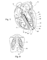
Figure 9 est un schéma de la cage thoracique et du coeur, illustrant la voie d'accès pour l'injection des microcâbles.
- The
Figure 1 is a schematic sectional view of the myocardium, showing the different cavities as well as the main pathways of electrical conduction. - The
Figure 2 illustrates a probe assembly according to the invention, in a configuration ready for implantation of the microcables. - The
Figure 3 illustrates, in isolation, the implantation needle of the entireFigure 2 . - The
Figure 4 shows the detail of the tip of the needle of theFigure 3 . - The
Figure 5 shows details of the tip and body of the needle of theFigure 2 , with the microcable in configuration ready for implantation. - The
Figure 6 is a sectional view of the distal end of the illustrated needle and microcableFigures 2 and 5 . - The
Figure 7 illustrates, in isolation, an anchoring cap to be screwed on the epicardium at the outlet of the microcable. - The
Figure 8 illustrates the anchor capsule of theFigure 7 , set in position on the needle of the set ready for implantation illustratedFigure 2 . - The
Figure 9 is a diagram of the rib cage and the heart, illustrating the access route for the injection of microcables.
La
Les ondes de dépolarisation qui prennent naissance dans le noeud sinoatrial 18 sont transmises au noeud atrioventriculaire 20 puis au faisceau de His 22 qui se divise en deux branches s'étendant le long du septum 16, avec une branche droite 24 dans la région de la paroi septale droite et une branche gauche 26 dans la région de la paroi septale gauche 28.The depolarization waves that originate in the
En particulier, la branche gauche 26 constitue une ligne de conduction électrique longitudinale rapide, avec une vitesse de l'ordre de 4 m/s. Cette branche gauche s'étend le long de la paroi gauche 28 du septum interventriculaire 16 le long de celle-ci jusqu'à la région de l'apex, puis remonte en 30 le long de la paroi libre 32 du ventricule gauche, approximativement jusqu'à la région de l'oreillette.In particular, the
L'idée de base de l'invention consiste à implanter une ou, très préférentiellement, plusieurs microsondes 34, 34', dont les extrémités actives respectives sont constituées de microcâbles 36, 36' pourvus chacun d'une ou plusieurs d'électrodes de stimulation 38, 38', de préférence un très grand nombre d'électrodes de très petite dimension chacune.The basic idea of the invention consists in implanting one or, more preferably,
L'invention n'est d'ailleurs pas limitée à la configuration décrite où l'on a illustré un ensemble à deux microsondes : en effet, il est possible d'envisager l'implantation non plus d'une, mais de plusieurs microsondes dans la paroi du septum interventriculaire et/ou dans la paroi libre du ventricule gauche. Une telle multiplication des microsondes conduira à former autour du ventricule gauche un "maillage" distribuant dans le muscle cardiaque un réseau de microélectrodes elles-mêmes portées par une pluralité de microcâbles rayonnant à partir de l'apex.The invention is also not limited to the described configuration where there is illustrated a set with two microbes: in fact, it is possible to envisage the implantation of not one, but several microbes in the wall of the interventricular septum and / or in the free wall of the ventricle left. Such multiplication of microworlds will lead to forming around the left ventricle a "mesh" distributing in the heart muscle a network of microelectrodes themselves carried by a plurality of microcables radiating from the apex.
Les microcâbles avec leurs électrodes permettent de reconstituer artificiellement une ligne de conduction parallèlement à la branche gauche du faisceau de His et d'exciter en une multiplicité de points le ventricule gauche tant du côté de la paroi septale que du côté de la paroi libre.The microcables with their electrodes make it possible to artificially reconstitute a conduction line parallel to the left branch of the His bundle and to excite in a multiplicity of points the left ventricle both on the side of the septal wall and on the side of the free wall.
De préférence, la surface totale des électrodes d'une microsonde ne dépasse pas 6 mm2, valeur du même ordre que la surface active d'une sonde endocavitaire standard. Le très faible diamètre du microcâble (typiquement 0,1 mm) permet de réaliser des électrodes sur une longueur cumulée de 20 mm sans dépasser la valeur précitée de 6 mm2 de surface dénudée : si l'on réduit la longueur d'une électrode individuelle à 0,5 mm, ceci laisse un potentiel de quarante électrodes réparties le long d'un même microcâble, donc une multiplication très importante des points de stimulation, qui en outre sont directement en contact avec les tissus, donc avec une excellente qualité de transmission de l'impulsion de stimulation de l'électrode aux tissus.Preferably, the total area of the electrodes of a microprobe does not exceed 6 mm 2 , a value of the same order as the active surface of a standard endocavity probe. The very small diameter of the microcable (typically 0.1 mm) makes it possible to produce electrodes over a cumulative length of 20 mm without exceeding the aforementioned value of 6 mm 2 of stripped surface: if the length of an individual electrode is reduced at 0.5 mm, this leaves a potential of forty electrodes distributed along the same microcable, thus a very important multiplication of the stimulation points, which moreover are directly in contact with the tissues, thus with an excellent quality of transmission the stimulating pulse of the electrode to the tissues.
Dans une variante, le microcâble peut toutefois être complètement dénudé dans sa partie active distale, configuration correspondant donc à une électrode unique de grande longueur.In a variant, however, the microcable can be completely stripped in its distal active portion, thus a configuration corresponding to a single electrode of great length.
Le microcâble peut comprendre un coeur constitué d'une pluralité de brins composites toronnés ensemble, avec par exemple un brin central entouré de six brins périphériques. Chaque brin composite est lui-même constitué d'un fil d'âme central en alliage de type MP35NLT, enveloppé d'une gaine en platine iridié (pour la radio-opacité et la biostabilité). Ces différents fils sont disponibles dans le commerce, par exemple auprès de la société Fort Wayne Metals Inc., Fort Wayne, USA, et sont utilisés dans le domaine médical.The microcable can comprise a core consisting of a plurality of composite strands stranded together, with for example a central strand surrounded by six peripheral strands. Each composite strand is itself made of an alloy center core wire type MP35NLT, wrapped with a platinum iridium sheath (for radio-opacity and biostability). These different yarns are commercially available, for example from Fort Wayne Metals Inc., Fort Wayne, USA, and are used in the medical field.
Le microcâble est revêtu d'une fine couche d'isolement, de l'ordre de 25 µm d'épaisseur. Les caractéristiques requises pour cette couche sont : résistance à la fatigue ; isolement électrique ; biocompatibilité à long terme ; biostabilité ; et possibilité de transformation et mise en oeuvre compatible avec le conducteur du câble de coeur. Pour réaliser cette couche d'isolement, on privilégiera les matériaux à forte inertie chimique comme les polymères fluorés, qui présentent également une très bonne qualité d'isolation. Parmi ces composés, on peut citer en particulier l'ETFE (éthylène tétrafluoroéthylène). Les procédés de réalisation de la couche d'isolement sur le câble de coeur sont, par exemple, la co-extrusion sur le conducteur ou l'échauffement d'un tube thermorétractable.The microcable is coated with a thin layer of insulation, of the order of 25 microns thick. The characteristics required for this layer are: resistance to fatigue; electrical isolation; long-term biocompatibility; biostability; and possibility of transformation and implementation compatible with the conductor of the heart cable. To achieve this insulation layer, preference will be given to materials with high chemical inertia such as fluoropolymers, which also have a very good quality of insulation. Among these compounds, mention may in particular be made of ETFE (ethylene tetrafluoroethylene). The processes for producing the insulation layer on the core cable are, for example, the coextrusion on the conductor or the heating of a heat-shrinkable tube.
La partie active du microcâble comporte dans l'exemple illustré une pluralité de parties dénudées formant une succession d'électrodes individuelles, constituant ensemble un réseau d'électrodes reliées en série permettant de multiplier les points de stimulation. Ceci permet de multiplier les possibilités de points de contact avec les tissus et d'assurer ainsi une diffusion multizone de l'énergie de stimulation en plusieurs points du ventricule gauche. Les électrodes sont formées par exemple par ablation plasma de la couche de parylène. Pour améliorer les performances électriques, ces zones peuvent être en outre revêtues par exemple de nitrure de titane.The active part of the microcable comprises in the illustrated example a plurality of stripped portions forming a succession of individual electrodes, together constituting an array of electrodes connected in series to multiply the stimulation points. This makes it possible to multiply the possibilities of points of contact with the tissues and thus to ensure a multizone diffusion of the stimulation energy at several points of the left ventricle. The electrodes are formed for example by plasma ablation of the parylene layer. To improve the electrical performance, these areas can be further coated for example with titanium nitride.
Du fait de la faible surface active cumulée, on bénéficie ainsi des avantages d'une sonde dite à "haute densité de courant", en termes à la fois d'efficacité physiologique de la stimulation et de moindre consommation d'énergie - ceci tout en maximisant l'étendue de la zone de contact physique, donc électrique, avec les tissus excitables. Par ailleurs, la localisation myocardique des électrodes limite les risques de stimulations phréniques.Due to the low cumulative active surface area, the advantages of a so-called "high current density" probe, in terms of both the physiological efficiency of the stimulation and the lower energy consumption, are also beneficial. maximizing the extent of the physical contact area, therefore electrical, with the excitable tissues. Moreover, the myocardial localization of the electrodes limits the risks of phrenic stimulations.
On va maintenant exposer, en référence aux
L'accessoire d'implantation, référencé 40, comprend une aiguille creuse 42 comportant une extrémité distale pointue 44, et montée à son extrémité proximale opposée sur un embout de préhension 46. L'embout de préhension 46 est avantageusement un embout de connexion de type Luer lock à verrou permettant le montage direct sur une seringue qui fera office de poignée de manipulation du système avec, en outre, possibilité d'injecter un produit de contraste ou du sérum physiologique.The implantation accessory, referenced 40, comprises a
L'aiguille présente un diamètre typique de 0,2 à 0,5 mm et peut être réalisée en un matériau superélastique tel que le nitinol, pour augmenter sa résistance à la plicature.The needle has a typical diameter of 0.2 to 0.5 mm and can be made of a superelastic material such as nitinol, to increase its resistance to plication.
Cette aiguille 42 a pour fonction d'assurer un support mécanique au microcâble 36 qui, du fait de son extrême finesse (typiquement 0,1 mm, de l'ordre de l'épaisseur d'un cheveu), ne pourrait pas être directement implanté dans la paroi du myocarde. L'extrémité du microcâble 36 ou 36' est repliée sur elle-même respectivement en 50, 50' sur environ 2 à 5 mm de manière à former un crochet de fixation introduit, comme on peut le voir sur les
La partie distale 44 de l'aiguille 42 présente une extrémité affutée 52 pour permettre une découpe fine des tissus sans les déchirer, minimisant ainsi leur endommagement et garantissant une cicatrisation rapide. Cette région comporte également un canal 54 prolongeant la lumière interne 48 pour permettre la mise en place et le retrait de l'extrémité repliée 50 du microcâble 36. Le bord proximal 56 de cette découpe n'est, en revanche, pas affuté pour éviter tout endommagement de la commissure 58 du microcâble.The
Le corps de l'aiguille est conformable manuellement par le médecin afin de s'adapter à la morphologie des parois à ponctionner.The body of the needle is manually adjustable by the doctor to adapt to the morphology of the walls to be punctured.
Le microcâble 36, accroché à l'aiguille à son extrémité distale par l'extrémité repliée 50, est maintenu légèrement sous tension le long de cette aiguille, étant bloqué en translation par clipsage dans un plot élastique 60 prévu sur l'embout de préhension 46. Le plot élastique 60 est par exemple un plot de silicone comprenant une fente longitudinale 62 dans laquelle le microcâble 36 est clipsé en force. Afin de renforcer la liaison temporaire entre aiguille et microcâble, ce dernier peut être enroulé autour du corps de l'aiguille avant d'être clipsé dans la fente 62 du plot silicone 60. Comme illustré
Il est important de noter que la méthode et l'outil d'implantation précédemment décrits permettent de disposer d'une sonde "prête à l'emploi" et "d'emploi facile" ne nécessitant :
- ni une intervention du médecin pour établir une connexion microcâble/corps de sonde,
- ni un pelage de l'aiguille de ponction.
- nor a doctor's intervention to establish a microcable connection / probe body,
- nor a peeling of the puncture needle.
Du point de vue électrique, les deux microcâbles 36, 36' peuvent être soit reliés ensemble, soit reliés à des pôles distincts du générateur, permettant dans ce dernier cas de programmer un délai entre la stimulation des deux parois (septale et libre) du ventricule gauche. Dans le cas d'un grand nombre de microcâbles, l'extrémité du corps de sonde peut être dotée d'un multiplexeur électronique permettant de contrôler la distribution d'énergie (séquencement, type de signal, niveau d'énergie) sur les différents microcâbles.From the electrical point of view, the two
Par ailleurs, il est possible d'envisager l'utilisation non seulement de microcâbles monopolaires comme ceux que l'on vient de décrire (c'est-à-dire dont toutes les électrodes sont électriquement reliées ensemble), mais également de microcâbles multipolaires, par exemple constitués par une pluralité de microcâbles élémentaires isolés individuellement et toronnés ensemble, afin de pouvoir polariser certaines électrodes (ou groupes d'électrodes) indépendamment les unes des autres. Une telle multipolarité permet notamment de disposer d'une fonction de "repositionnement électronique", laquelle offre de nombreuses possibilités de stimulation des tissus à travers le choix et la polarisation de certaines lignes de conduction parmi plusieurs incluses dans la microsonde, et de programmer spécifiquement des zones de stimulation ou de défibrillation en fonction de la thérapie.Moreover, it is possible to envisage the use not only of monopolar microcables such as those just described (that is to say of which all the electrodes are electrically connected together), but also of multipolar microcables, for example constituted by a plurality of elementary microcables individually isolated and stranded together, in order to be able to bias some electrodes (or groups of electrodes) independently of each other. Such multipolarity notably makes it possible to have an "electronic repositioning" function, which offers numerous possibilities for tissue stimulation through the choice and polarization of some of the conduction lines among several included in the microprobe, and to specifically program areas of stimulation or defibrillation depending on the therapy.
Les
Le rôle de cette capsule d'ancrage est double :
- dissocier la partie du microcâble implantée dans le myocarde du reste de la sonde, notamment pour éviter après implantation et avant la fin de l'intervention un déplacement du microcâble consécutif à une traction accidentelle exercée sur le corps de sonde ;
- gérer l'angulation de sortie (typiquement à angle droit) du microcâble à proximité du point d'émergence, en évitant les mouvements de forte amplitude autour de cette zone fortement courbée, donc contrainte (même si des boucles de compliance sont prévues dans la partie émergée de la microsonde pour absorber les contraintes et les mouvements entre le point d'émergence et le corps de sonde proprement dit).
- dissociating the portion of the microcable implanted in the myocardium from the remainder of the probe, in particular to avoid, after implantation and before the end of the procedure, a displacement of the microcable subsequent to an accidental traction exerted on the probe body;
- manage the output angulation (typically at right angles) of the microcable near the emergence point, avoiding high amplitude movements around this strongly curved area, therefore constrained (even if compliance loops are provided in the part emerged from the microprobe to absorb the stresses and movements between the point of emergence and the probe body itself).
La capsule d'ancrage 60 illustrée
D'autres moyens de maintien en place du microcâble à son point d'émergence peuvent être envisagés, parmi lesquels on peut notamment citer le dépôt d'un point de colle d'un adhésif chirurgical biocompatible tel que Bioglue (marque déposée) de la société Cryolife Inc., USA.Other means of holding the microcable in place at its point of emergence can be envisaged, among which there may be mentioned the deposition of a glue point of a biocompatible surgical adhesive such as Bioglue (registered trademark) of the company. Cryolife Inc., USA.
L'un des avantages majeurs de l'invention est la possibilité d'injecter les microcâbles par une manoeuvre chirurgicale peu invasive, typiquement une approche de type sub-xiphoïdienne, et en n'utilisant que des accessoires conventionnels.One of the major advantages of the invention is the possibility of injecting the microcables by a minimally invasive surgical maneuver, typically a sub-xiphoid type approach, and using only conventional accessories.
Comme illustré
L'extrémité de l'aiguille peut être dotée de moyens de repérage (marqueur radio-opaque, échographique, etc.) permettant de guider l'opérateur pendant la manoeuvre, afin notamment de s'assurer que la trajectoire choisie reste majoritairement dans le muscle. Il est également possible d'injecter du produit de contraste par la seringue à travers l'aiguille, dans le même but.The end of the needle may be provided with means of identification (radio-opaque marker, ultrasound, etc.) to guide the operator during the maneuver, in particular to ensure that the chosen path remains predominantly in the muscle . It is also possible to inject contrast material through the syringe through the needle for the same purpose.
L'aiguille ayant atteint sa position finale, l'opérateur libère le microcâble du plot élastique 60 qui le clipsait, et tire l'aiguille. Le corps du microcâble s'oppose au mouvement de retour sous l'effet de la compression des tissus, libérant ainsi l'extrémité repliée 50 qui fixe alors, par effet de crochet, le microcâble de façon définitive.The needle having reached its final position, the operator releases the microcable of the
La présence des crochets 50, 50' formés par la partie repliée de l'extrémité distale des microcâbles 36, 36' procure une bonne résistance à l'extraction au moment de la manoeuvre d'injection, puis sous l'effet des contraintes internes sous l'effet des battements cardiaques.The presence of the
Si toutefois l'on souhaite extraire complètement le microcâble, un effort soutenu de traction externe aura pour effet de redresser la plicature, permettant ainsi le retrait du microcâble. Le système de l'invention peut donc être explanté aisément et sans dommages majeurs pour les tissus, contrairement à la quasi-totalité des systèmes connus de stimulation du ventricule gauche.If, however, it is desired to fully extract the microcable, a sustained external tensile force will have the effect of straightening the plication, thereby allowing the microcable to be removed. The system of the invention can therefore be explanted easily and without major damage to tissues, unlike almost all known left ventricular stimulation systems.
Claims (15)
cette sonde (34, 34') étant une microsonde constituée dans sa partie active, distale par un microcâble (36, 36') comportant un coeur électriquement conducteur revêtu d'une couche électriquement isolante, la partie active comprenant une série de zones dénudées (38, 38') du microcâble formant électrodes de stimulation électriquement reliées ensemble ; et
caractérisé en ce que :
de manière à permettre l'implantation de la microsonde par pénétration simultanée de l'aiguille et du microcâble porté par cette aiguille, dans ladite épaisseur de la paroi du septum interventriculaire (16) ou de la paroi libre (32) du ventricule gauche,.
this probe (34, 34 ') being a microprobe formed in its active part, distal by a microcable (36, 36') having an electrically conductive core coated with an electrically insulating layer, the active part comprising a series of stripped zones ( 38, 38 ') of the microcable forming stimulation electrodes electrically connected together; and
characterized in that
so as to allow implantation of the microprobe by simultaneous penetration of the needle and the microcable carried by this needle, in said thickness of the wall of the interventricular septum (16) or the free wall (32) of the left ventricle ,.
Applications Claiming Priority (1)
| Application Number | Priority Date | Filing Date | Title |
|---|---|---|---|
| FR1259761 | 2012-10-12 |
Publications (2)
| Publication Number | Publication Date |
|---|---|
| EP2719425A1 true EP2719425A1 (en) | 2014-04-16 |
| EP2719425B1 EP2719425B1 (en) | 2015-04-08 |
Family
ID=47428710
Family Applications (1)
| Application Number | Title | Priority Date | Filing Date |
|---|---|---|---|
| EP13172889.1A Active EP2719425B1 (en) | 2012-10-12 | 2013-06-19 | Implantable cardiac stimulation probe along the ventricular septal wall and/or the left ventricle free wall |
Country Status (2)
| Country | Link |
|---|---|
| US (1) | US9101758B2 (en) |
| EP (1) | EP2719425B1 (en) |
Cited By (1)
| Publication number | Priority date | Publication date | Assignee | Title |
|---|---|---|---|---|
| WO2020207118A1 (en) * | 2019-04-08 | 2020-10-15 | 中国石油大学(北京) | Puncture needle device for entering left ventricle through peripheral artery to puncture interventricular septum and preparation method |
Families Citing this family (1)
| Publication number | Priority date | Publication date | Assignee | Title |
|---|---|---|---|---|
| FR3115212A1 (en) * | 2020-10-15 | 2022-04-22 | Sorin Crm Sas | Set of an implantation accessory and a flexible implantable stimulation probe |
Citations (10)
| Publication number | Priority date | Publication date | Assignee | Title |
|---|---|---|---|---|
| US6718206B2 (en) * | 2001-10-23 | 2004-04-06 | Medtronic, Inc. | Permanent atrial-his-ventricular sequential pacing |
| US20050080470A1 (en) * | 2003-10-09 | 2005-04-14 | Randy Westlund | Intramyocardial lead implantation system and method |
| US20050209668A1 (en) * | 2004-03-09 | 2005-09-22 | Friedman Paul A | Novel sheath and electrical lead |
| US7027876B2 (en) * | 2001-10-12 | 2006-04-11 | Medtronic, Inc. | Lead system for providing electrical stimulation to the Bundle of His |
| US20060106442A1 (en) * | 2004-05-19 | 2006-05-18 | The Board Of Trustees Of The Leland Stanford Junior University | Devices and methods for treating cardiac pathologies |
| US20060258978A1 (en) * | 2003-07-02 | 2006-11-16 | St. Jude Medical, Atrial Fibrillation Division, Inc. | Steerable and shapable catheter employing fluid force |
| US20080294229A1 (en) * | 2006-10-17 | 2008-11-27 | Friedman Paul A | Helical Electrodes for Intramyocardial Pacing and Sensing |
| US20110066057A1 (en) * | 2005-10-31 | 2011-03-17 | Zdeblick Mark J | Electrical Angle Gauge |
| EP2384784A1 (en) * | 2010-05-05 | 2011-11-09 | Sorin CRM SAS | Assembly for endocavitary stimulation/defibrillation of the left ventricle |
| US20120136423A1 (en) * | 2010-11-29 | 2012-05-31 | Sorin Crm Sas | System for Stimulation and/or Defibrillation of the Left Ventricle Endocardially or From a Vein In the Coronary System |
Family Cites Families (3)
| Publication number | Priority date | Publication date | Assignee | Title |
|---|---|---|---|---|
| US7317950B2 (en) | 2002-11-16 | 2008-01-08 | The Regents Of The University Of California | Cardiac stimulation system with delivery of conductive agent |
| US8121687B2 (en) | 2004-11-01 | 2012-02-21 | Proteus Biomedical, Inc. | Cardiac motion characterization by strain measurement |
| US7515971B1 (en) | 2005-09-09 | 2009-04-07 | Pacesetter, Inc. | Left atrial pressure sensor lead |
-
2013
- 2013-06-19 EP EP13172889.1A patent/EP2719425B1/en active Active
- 2013-10-11 US US14/052,459 patent/US9101758B2/en active Active
Patent Citations (10)
| Publication number | Priority date | Publication date | Assignee | Title |
|---|---|---|---|---|
| US7027876B2 (en) * | 2001-10-12 | 2006-04-11 | Medtronic, Inc. | Lead system for providing electrical stimulation to the Bundle of His |
| US6718206B2 (en) * | 2001-10-23 | 2004-04-06 | Medtronic, Inc. | Permanent atrial-his-ventricular sequential pacing |
| US20060258978A1 (en) * | 2003-07-02 | 2006-11-16 | St. Jude Medical, Atrial Fibrillation Division, Inc. | Steerable and shapable catheter employing fluid force |
| US20050080470A1 (en) * | 2003-10-09 | 2005-04-14 | Randy Westlund | Intramyocardial lead implantation system and method |
| US20050209668A1 (en) * | 2004-03-09 | 2005-09-22 | Friedman Paul A | Novel sheath and electrical lead |
| US20060106442A1 (en) * | 2004-05-19 | 2006-05-18 | The Board Of Trustees Of The Leland Stanford Junior University | Devices and methods for treating cardiac pathologies |
| US20110066057A1 (en) * | 2005-10-31 | 2011-03-17 | Zdeblick Mark J | Electrical Angle Gauge |
| US20080294229A1 (en) * | 2006-10-17 | 2008-11-27 | Friedman Paul A | Helical Electrodes for Intramyocardial Pacing and Sensing |
| EP2384784A1 (en) * | 2010-05-05 | 2011-11-09 | Sorin CRM SAS | Assembly for endocavitary stimulation/defibrillation of the left ventricle |
| US20120136423A1 (en) * | 2010-11-29 | 2012-05-31 | Sorin Crm Sas | System for Stimulation and/or Defibrillation of the Left Ventricle Endocardially or From a Vein In the Coronary System |
Cited By (1)
| Publication number | Priority date | Publication date | Assignee | Title |
|---|---|---|---|---|
| WO2020207118A1 (en) * | 2019-04-08 | 2020-10-15 | 中国石油大学(北京) | Puncture needle device for entering left ventricle through peripheral artery to puncture interventricular septum and preparation method |
Also Published As
| Publication number | Publication date |
|---|---|
| US20140107756A1 (en) | 2014-04-17 |
| US9101758B2 (en) | 2015-08-11 |
| EP2719425B1 (en) | 2015-04-08 |
Similar Documents
| Publication | Publication Date | Title |
|---|---|---|
| EP2384784B1 (en) | Assembly for endocavitary stimulation/defibrillation of the left ventricle | |
| EP2719424B1 (en) | Intraseptal probe for left ventricular stimulation | |
| EP2457612B1 (en) | Unit for stimulation/defibrillation of the left ventricle via the endocavity or from a vein of the coronary network | |
| EP2574368B1 (en) | Multizone epicardial stimulation probe | |
| EP2455131B1 (en) | Probe for stimulating a left cavity of the heart which can be implanted in the coronary network | |
| EP2881141B1 (en) | Implantable intracardiac capsule on a thin wall, in particular the septal wall | |
| US5871530A (en) | Intracardiac defibrillation leads | |
| EP2929910B1 (en) | Intracardiac capsule and accessory for explanting same | |
| BE1004208A5 (en) | Flat electrode in cardiac defibrillation /cardioversion coil | |
| CH667395A5 (en) | APPARATUS FOR DETECTING HEART RATE DISORDERS AND FOR EMITTING DEFIBRILLATION, CARDIOVERSION OR STIMULATION PULSES. | |
| EP0614677B1 (en) | Electrocatheter for sequential heart pacing (DDD) with a single head positioned through the coronary sinus | |
| EP2878332B1 (en) | Detection/stimulation microprobe implantable in a vessel of the venous, lymphatic or arterial network | |
| EP2719422B1 (en) | Implantable multipolar detection/stimulation microprobe | |
| FR2786701A1 (en) | Electrical heart stimulator or defibrillator has conductor, electrode(s) and atrium branch | |
| EP2246091B1 (en) | Endocardiac stimulation or defibrillation probe with a retractable screw | |
| EP2572751B1 (en) | Probe for stimulation in an extended region of a cardiac chamber, which can be implanted by wire guidance in the deep coronary network | |
| EP3058983B1 (en) | Detection/stimulation microprobe, in particular for multipoint neuromodulation of the central nervous system | |
| FR2801510A1 (en) | Electrical conductor comprises electrical body with proximal and distal sections, electrode, a proximal section comprising an electrical connector, distal extremity and electrical conductor useful for stimulating cardiac defibrillation | |
| FR2801509A1 (en) | Electrical stimulation probe, used for heart stimulation and/or defibrillation, has probe body of varying rigidity, and inserted into coronary vein until it reaches coronary sinus | |
| EP2275170B1 (en) | Assembly suitable for implantation in the coronary sinus, including a stimulation probe with anchoring screw | |
| EP2308550B1 (en) | Epicardial stimulation/defibrillation probe with screw, suitable for implantation via a catheter-guide inserted in the pericardial cavity | |
| EP2559453B1 (en) | Lead implantable in the coronary vessels for multi-zone stimulation of a left heart chamber | |
| EP2719425B1 (en) | Implantable cardiac stimulation probe along the ventricular septal wall and/or the left ventricle free wall | |
| FR2757773A1 (en) | Human heart implanted device for auricular and ventricular stimulation and detection of heart | |
| EP2719423B1 (en) | Atraumatic detection/stimulation microprobe |
Legal Events
| Date | Code | Title | Description |
|---|---|---|---|
| PUAI | Public reference made under article 153(3) epc to a published international application that has entered the european phase |
Free format text: ORIGINAL CODE: 0009012 |
|
| AK | Designated contracting states |
Kind code of ref document: A1 Designated state(s): AL AT BE BG CH CY CZ DE DK EE ES FI FR GB GR HR HU IE IS IT LI LT LU LV MC MK MT NL NO PL PT RO RS SE SI SK SM TR |
|
| AX | Request for extension of the european patent |
Extension state: BA ME |
|
| 17P | Request for examination filed |
Effective date: 20140827 |
|
| RBV | Designated contracting states (corrected) |
Designated state(s): AL AT BE BG CH CY CZ DE DK EE ES FI FR GB GR HR HU IE IS IT LI LT LU LV MC MK MT NL NO PL PT RO RS SE SI SK SM TR |
|
| RIC1 | Information provided on ipc code assigned before grant |
Ipc: A61N 1/375 20060101ALI20141002BHEP Ipc: A61N 1/05 20060101ALI20141002BHEP Ipc: A61N 1/362 20060101AFI20141002BHEP |
|
| GRAP | Despatch of communication of intention to grant a patent |
Free format text: ORIGINAL CODE: EPIDOSNIGR1 |
|
| INTG | Intention to grant announced |
Effective date: 20141119 |
|
| GRAS | Grant fee paid |
Free format text: ORIGINAL CODE: EPIDOSNIGR3 |
|
| GRAA | (expected) grant |
Free format text: ORIGINAL CODE: 0009210 |
|
| AK | Designated contracting states |
Kind code of ref document: B1 Designated state(s): AL AT BE BG CH CY CZ DE DK EE ES FI FR GB GR HR HU IE IS IT LI LT LU LV MC MK MT NL NO PL PT RO RS SE SI SK SM TR |
|
| REG | Reference to a national code |
Ref country code: GB Ref legal event code: FG4D Free format text: NOT ENGLISH |
|
| REG | Reference to a national code |
Ref country code: CH Ref legal event code: EP |
|
| REG | Reference to a national code |
Ref country code: IE Ref legal event code: FG4D Free format text: LANGUAGE OF EP DOCUMENT: FRENCH |
|
| REG | Reference to a national code |
Ref country code: AT Ref legal event code: REF Ref document number: 720065 Country of ref document: AT Kind code of ref document: T Effective date: 20150515 |
|
| REG | Reference to a national code |
Ref country code: DE Ref legal event code: R096 Ref document number: 602013001443 Country of ref document: DE Effective date: 20150521 |
|
| REG | Reference to a national code |
Ref country code: FR Ref legal event code: PLFP Year of fee payment: 3 |
|
| REG | Reference to a national code |
Ref country code: AT Ref legal event code: MK05 Ref document number: 720065 Country of ref document: AT Kind code of ref document: T Effective date: 20150408 |
|
| REG | Reference to a national code |
Ref country code: NL Ref legal event code: VDEP Effective date: 20150408 |
|
| REG | Reference to a national code |
Ref country code: LT Ref legal event code: MG4D |
|
| PG25 | Lapsed in a contracting state [announced via postgrant information from national office to epo] |
Ref country code: NL Free format text: LAPSE BECAUSE OF FAILURE TO SUBMIT A TRANSLATION OF THE DESCRIPTION OR TO PAY THE FEE WITHIN THE PRESCRIBED TIME-LIMIT Effective date: 20150408 |
|
| PG25 | Lapsed in a contracting state [announced via postgrant information from national office to epo] |
Ref country code: LT Free format text: LAPSE BECAUSE OF FAILURE TO SUBMIT A TRANSLATION OF THE DESCRIPTION OR TO PAY THE FEE WITHIN THE PRESCRIBED TIME-LIMIT Effective date: 20150408 Ref country code: HR Free format text: LAPSE BECAUSE OF FAILURE TO SUBMIT A TRANSLATION OF THE DESCRIPTION OR TO PAY THE FEE WITHIN THE PRESCRIBED TIME-LIMIT Effective date: 20150408 Ref country code: ES Free format text: LAPSE BECAUSE OF FAILURE TO SUBMIT A TRANSLATION OF THE DESCRIPTION OR TO PAY THE FEE WITHIN THE PRESCRIBED TIME-LIMIT Effective date: 20150408 Ref country code: NO Free format text: LAPSE BECAUSE OF FAILURE TO SUBMIT A TRANSLATION OF THE DESCRIPTION OR TO PAY THE FEE WITHIN THE PRESCRIBED TIME-LIMIT Effective date: 20150708 Ref country code: FI Free format text: LAPSE BECAUSE OF FAILURE TO SUBMIT A TRANSLATION OF THE DESCRIPTION OR TO PAY THE FEE WITHIN THE PRESCRIBED TIME-LIMIT Effective date: 20150408 Ref country code: PT Free format text: LAPSE BECAUSE OF FAILURE TO SUBMIT A TRANSLATION OF THE DESCRIPTION OR TO PAY THE FEE WITHIN THE PRESCRIBED TIME-LIMIT Effective date: 20150810 |
|
| PG25 | Lapsed in a contracting state [announced via postgrant information from national office to epo] |
Ref country code: IS Free format text: LAPSE BECAUSE OF FAILURE TO SUBMIT A TRANSLATION OF THE DESCRIPTION OR TO PAY THE FEE WITHIN THE PRESCRIBED TIME-LIMIT Effective date: 20150808 Ref country code: RS Free format text: LAPSE BECAUSE OF FAILURE TO SUBMIT A TRANSLATION OF THE DESCRIPTION OR TO PAY THE FEE WITHIN THE PRESCRIBED TIME-LIMIT Effective date: 20150408 Ref country code: AT Free format text: LAPSE BECAUSE OF FAILURE TO SUBMIT A TRANSLATION OF THE DESCRIPTION OR TO PAY THE FEE WITHIN THE PRESCRIBED TIME-LIMIT Effective date: 20150408 Ref country code: GR Free format text: LAPSE BECAUSE OF FAILURE TO SUBMIT A TRANSLATION OF THE DESCRIPTION OR TO PAY THE FEE WITHIN THE PRESCRIBED TIME-LIMIT Effective date: 20150709 Ref country code: LV Free format text: LAPSE BECAUSE OF FAILURE TO SUBMIT A TRANSLATION OF THE DESCRIPTION OR TO PAY THE FEE WITHIN THE PRESCRIBED TIME-LIMIT Effective date: 20150408 |
|
| REG | Reference to a national code |
Ref country code: DE Ref legal event code: R097 Ref document number: 602013001443 Country of ref document: DE |
|
| PG25 | Lapsed in a contracting state [announced via postgrant information from national office to epo] |
Ref country code: DK Free format text: LAPSE BECAUSE OF FAILURE TO SUBMIT A TRANSLATION OF THE DESCRIPTION OR TO PAY THE FEE WITHIN THE PRESCRIBED TIME-LIMIT Effective date: 20150408 Ref country code: EE Free format text: LAPSE BECAUSE OF FAILURE TO SUBMIT A TRANSLATION OF THE DESCRIPTION OR TO PAY THE FEE WITHIN THE PRESCRIBED TIME-LIMIT Effective date: 20150408 Ref country code: MC Free format text: LAPSE BECAUSE OF FAILURE TO SUBMIT A TRANSLATION OF THE DESCRIPTION OR TO PAY THE FEE WITHIN THE PRESCRIBED TIME-LIMIT Effective date: 20150408 |
|
| PLBE | No opposition filed within time limit |
Free format text: ORIGINAL CODE: 0009261 |
|
| STAA | Information on the status of an ep patent application or granted ep patent |
Free format text: STATUS: NO OPPOSITION FILED WITHIN TIME LIMIT |
|
| PG25 | Lapsed in a contracting state [announced via postgrant information from national office to epo] |
Ref country code: SK Free format text: LAPSE BECAUSE OF FAILURE TO SUBMIT A TRANSLATION OF THE DESCRIPTION OR TO PAY THE FEE WITHIN THE PRESCRIBED TIME-LIMIT Effective date: 20150408 Ref country code: RO Free format text: LAPSE BECAUSE OF NON-PAYMENT OF DUE FEES Effective date: 20150408 Ref country code: PL Free format text: LAPSE BECAUSE OF FAILURE TO SUBMIT A TRANSLATION OF THE DESCRIPTION OR TO PAY THE FEE WITHIN THE PRESCRIBED TIME-LIMIT Effective date: 20150408 Ref country code: LU Free format text: LAPSE BECAUSE OF FAILURE TO SUBMIT A TRANSLATION OF THE DESCRIPTION OR TO PAY THE FEE WITHIN THE PRESCRIBED TIME-LIMIT Effective date: 20150619 Ref country code: CZ Free format text: LAPSE BECAUSE OF FAILURE TO SUBMIT A TRANSLATION OF THE DESCRIPTION OR TO PAY THE FEE WITHIN THE PRESCRIBED TIME-LIMIT Effective date: 20150408 |
|
| 26N | No opposition filed |
Effective date: 20160111 |
|
| REG | Reference to a national code |
Ref country code: IE Ref legal event code: MM4A |
|
| PG25 | Lapsed in a contracting state [announced via postgrant information from national office to epo] |
Ref country code: IE Free format text: LAPSE BECAUSE OF NON-PAYMENT OF DUE FEES Effective date: 20150619 |
|
| REG | Reference to a national code |
Ref country code: FR Ref legal event code: PLFP Year of fee payment: 4 |
|
| PG25 | Lapsed in a contracting state [announced via postgrant information from national office to epo] |
Ref country code: SI Free format text: LAPSE BECAUSE OF FAILURE TO SUBMIT A TRANSLATION OF THE DESCRIPTION OR TO PAY THE FEE WITHIN THE PRESCRIBED TIME-LIMIT Effective date: 20150408 |
|
| PG25 | Lapsed in a contracting state [announced via postgrant information from national office to epo] |
Ref country code: MT Free format text: LAPSE BECAUSE OF FAILURE TO SUBMIT A TRANSLATION OF THE DESCRIPTION OR TO PAY THE FEE WITHIN THE PRESCRIBED TIME-LIMIT Effective date: 20150408 |
|
| REG | Reference to a national code |
Ref country code: CH Ref legal event code: PL |
|
| PG25 | Lapsed in a contracting state [announced via postgrant information from national office to epo] |
Ref country code: LI Free format text: LAPSE BECAUSE OF NON-PAYMENT OF DUE FEES Effective date: 20160630 Ref country code: CH Free format text: LAPSE BECAUSE OF NON-PAYMENT OF DUE FEES Effective date: 20160630 |
|
| REG | Reference to a national code |
Ref country code: FR Ref legal event code: PLFP Year of fee payment: 5 |
|
| PG25 | Lapsed in a contracting state [announced via postgrant information from national office to epo] |
Ref country code: HU Free format text: LAPSE BECAUSE OF FAILURE TO SUBMIT A TRANSLATION OF THE DESCRIPTION OR TO PAY THE FEE WITHIN THE PRESCRIBED TIME-LIMIT; INVALID AB INITIO Effective date: 20130619 Ref country code: BG Free format text: LAPSE BECAUSE OF FAILURE TO SUBMIT A TRANSLATION OF THE DESCRIPTION OR TO PAY THE FEE WITHIN THE PRESCRIBED TIME-LIMIT Effective date: 20150408 |
|
| PG25 | Lapsed in a contracting state [announced via postgrant information from national office to epo] |
Ref country code: CY Free format text: LAPSE BECAUSE OF FAILURE TO SUBMIT A TRANSLATION OF THE DESCRIPTION OR TO PAY THE FEE WITHIN THE PRESCRIBED TIME-LIMIT Effective date: 20150408 Ref country code: SE Free format text: LAPSE BECAUSE OF FAILURE TO SUBMIT A TRANSLATION OF THE DESCRIPTION OR TO PAY THE FEE WITHIN THE PRESCRIBED TIME-LIMIT Effective date: 20150408 |
|
| PG25 | Lapsed in a contracting state [announced via postgrant information from national office to epo] |
Ref country code: BE Free format text: LAPSE BECAUSE OF NON-PAYMENT OF DUE FEES Effective date: 20150630 |
|
| PG25 | Lapsed in a contracting state [announced via postgrant information from national office to epo] |
Ref country code: TR Free format text: LAPSE BECAUSE OF FAILURE TO SUBMIT A TRANSLATION OF THE DESCRIPTION OR TO PAY THE FEE WITHIN THE PRESCRIBED TIME-LIMIT Effective date: 20150408 |
|
| REG | Reference to a national code |
Ref country code: FR Ref legal event code: PLFP Year of fee payment: 6 |
|
| PG25 | Lapsed in a contracting state [announced via postgrant information from national office to epo] |
Ref country code: SM Free format text: LAPSE BECAUSE OF FAILURE TO SUBMIT A TRANSLATION OF THE DESCRIPTION OR TO PAY THE FEE WITHIN THE PRESCRIBED TIME-LIMIT Effective date: 20150408 |
|
| PG25 | Lapsed in a contracting state [announced via postgrant information from national office to epo] |
Ref country code: MK Free format text: LAPSE BECAUSE OF FAILURE TO SUBMIT A TRANSLATION OF THE DESCRIPTION OR TO PAY THE FEE WITHIN THE PRESCRIBED TIME-LIMIT Effective date: 20150408 |
|
| PG25 | Lapsed in a contracting state [announced via postgrant information from national office to epo] |
Ref country code: AL Free format text: LAPSE BECAUSE OF FAILURE TO SUBMIT A TRANSLATION OF THE DESCRIPTION OR TO PAY THE FEE WITHIN THE PRESCRIBED TIME-LIMIT Effective date: 20150408 |
|
| PGFP | Annual fee paid to national office [announced via postgrant information from national office to epo] |
Ref country code: IT Payment date: 20230608 Year of fee payment: 11 Ref country code: FR Payment date: 20230622 Year of fee payment: 11 Ref country code: DE Payment date: 20230613 Year of fee payment: 11 |
|
| P01 | Opt-out of the competence of the unified patent court (upc) registered |
Effective date: 20230714 |
|
| PGFP | Annual fee paid to national office [announced via postgrant information from national office to epo] |
Ref country code: GB Payment date: 20230620 Year of fee payment: 11 |