EP2722663A1 - Sensor chip used in specimen detection device and specimen detection device using sensor chip - Google Patents
Sensor chip used in specimen detection device and specimen detection device using sensor chip Download PDFInfo
- Publication number
- EP2722663A1 EP2722663A1 EP12801279.6A EP12801279A EP2722663A1 EP 2722663 A1 EP2722663 A1 EP 2722663A1 EP 12801279 A EP12801279 A EP 12801279A EP 2722663 A1 EP2722663 A1 EP 2722663A1
- Authority
- EP
- European Patent Office
- Prior art keywords
- flow passage
- solution
- outflow hole
- inflow
- inflow outflow
- Prior art date
- Legal status (The legal status is an assumption and is not a legal conclusion. Google has not performed a legal analysis and makes no representation as to the accuracy of the status listed.)
- Granted
Links
Images


Classifications
-
- G—PHYSICS
- G01—MEASURING; TESTING
- G01N—INVESTIGATING OR ANALYSING MATERIALS BY DETERMINING THEIR CHEMICAL OR PHYSICAL PROPERTIES
- G01N21/00—Investigating or analysing materials by the use of optical means, i.e. using sub-millimetre waves, infrared, visible or ultraviolet light
- G01N21/01—Arrangements or apparatus for facilitating the optical investigation
- G01N21/03—Cuvette constructions
- G01N21/05—Flow-through cuvettes
-
- G—PHYSICS
- G01—MEASURING; TESTING
- G01N—INVESTIGATING OR ANALYSING MATERIALS BY DETERMINING THEIR CHEMICAL OR PHYSICAL PROPERTIES
- G01N21/00—Investigating or analysing materials by the use of optical means, i.e. using sub-millimetre waves, infrared, visible or ultraviolet light
- G01N21/17—Systems in which incident light is modified in accordance with the properties of the material investigated
- G01N21/55—Specular reflectivity
- G01N21/552—Attenuated total reflection
- G01N21/553—Attenuated total reflection and using surface plasmons
-
- G—PHYSICS
- G01—MEASURING; TESTING
- G01N—INVESTIGATING OR ANALYSING MATERIALS BY DETERMINING THEIR CHEMICAL OR PHYSICAL PROPERTIES
- G01N21/00—Investigating or analysing materials by the use of optical means, i.e. using sub-millimetre waves, infrared, visible or ultraviolet light
- G01N21/62—Systems in which the material investigated is excited whereby it emits light or causes a change in wavelength of the incident light
- G01N21/63—Systems in which the material investigated is excited whereby it emits light or causes a change in wavelength of the incident light optically excited
- G01N21/64—Fluorescence; Phosphorescence
- G01N21/645—Specially adapted constructive features of fluorimeters
- G01N21/648—Specially adapted constructive features of fluorimeters using evanescent coupling or surface plasmon coupling for the excitation of fluorescence
-
- G—PHYSICS
- G01—MEASURING; TESTING
- G01N—INVESTIGATING OR ANALYSING MATERIALS BY DETERMINING THEIR CHEMICAL OR PHYSICAL PROPERTIES
- G01N21/00—Investigating or analysing materials by the use of optical means, i.e. using sub-millimetre waves, infrared, visible or ultraviolet light
- G01N21/01—Arrangements or apparatus for facilitating the optical investigation
- G01N21/03—Cuvette constructions
- G01N2021/0325—Cells for testing reactions, e.g. containing reagents
-
- G—PHYSICS
- G01—MEASURING; TESTING
- G01N—INVESTIGATING OR ANALYSING MATERIALS BY DETERMINING THEIR CHEMICAL OR PHYSICAL PROPERTIES
- G01N21/00—Investigating or analysing materials by the use of optical means, i.e. using sub-millimetre waves, infrared, visible or ultraviolet light
- G01N21/01—Arrangements or apparatus for facilitating the optical investigation
- G01N21/03—Cuvette constructions
- G01N2021/0346—Capillary cells; Microcells
Definitions
- the present invention relates to a sensor chip that is used in a specimen material detection device and a specimen material detection device using a sensor chip for a surface plasmon resonance device (hereafter referred to as an SPR device) using a phenomenon of a surface plasmon resonance (SPR: Surface Plasmon Resonance) and a surface plasmon-field enhanced fluorescence spectroscopy measurement device (hereafter referred to as an SPFS device) using a principle of a surface plasmon excitation enhanced fluorescence spectroscopy (SPFS: Surface Plasmon-field enhanced Fluorescence Spectroscopy) for the fields of a medical care and biotechnology for instance.
- SPR Surface Plasmon Resonance
- SPFS device surface plasmon-field enhanced fluorescence spectroscopy measurement device
- an SPR device in which a phenomenon for obtaining a high optical output by a resonance of an electron and a light in a minute region of a nanometer level or the like (a surface plasmon resonance (SPR: Surface Plasmon Resonance) phenomenon) is put to practical use and an extremely fine analyte in a biological body is detected for instance.
- SPR Surface Plasmon Resonance
- an SPFS device in which the analyte detection can be carried out with a higher degree of accuracy as compared with the SPR device based on a principle of a surface plasmon excitation enhanced fluorescence spectroscopy (SPFS) for putting a surface plasmon resonance phenomenon to practical use.
- SPFS surface plasmon excitation enhanced fluorescence spectroscopy
- SPFS surface plasmon excitation enhanced fluorescence spectroscopy
- ATR attenuated total reflectance
- a specimen material detection device such as an SPR device and an SPFS device
- a specimen material solution that contains an analyte (antigen) that is a detection target is prepared in advance, the specimen material solution is sent to a fine flow passage, and an analyte (antigen) is captured with a ligand (antibody) that is fixed to a detection region (a reaction field) that is disposed in the fine flow passage.
- a solution sending of a ligand solution, a specimen material solution, and a cleaning solution is carried out in a fine flow passage by ordinary.
- a specimen material detection device that is called a circulation type in which a specimen material solution is circulated and passes through a detection region in a repetitive manner
- Patent Literature 1 Japanese Patent Application Laid-Open Publication No. 2006-90985 discloses a specimen material detection device that is called a reciprocation type as described above.
- the measurement device that is disclosed in the Patent Literature 1 is provided with a first sending and discharge means such as a pipette capable of performing a discharge of an analyte solution to and the suction of an analyte solution from a flow passage.
- a first sending and discharge means such as a pipette capable of performing a discharge of an analyte solution to and the suction of an analyte solution from a flow passage.
- Any one of the specimen material detection devices of a one pass type, a circulation type, and a reciprocation type as described above has the following problem.
- Fig. 23 is a schematic view for showing a specimen material detection device 100 of a reciprocation type for instance.
- the specimen material detection device 100 is provided with a fine flow passage 102 and a solution sending pump 106 that is configured to send a solution 104 such as a ligand solution, a specimen material solution, and a cleaning solution.
- a solution 104 such as a ligand solution, a specimen material solution, and a cleaning solution.
- the fine flow passage 102 is provided with an inflow outflow hole 108 that is an inflow outflow hole that is configured to make a solution 104 inflow to and outflow from the fine flow passage 102 on an edge part of one side in a direction of the flow passage, and an outlet hole 110 that is an outlet of a solution 104 that outflows from the inflow outflow hole 108 on an edge part of the other side in a direction of the flow passage.
- a detection region (a reaction field) 112 to which an antibody (a ligand) that reacts with a specific antigen is fixed is disposed on a bottom surface in the fine flow passage 102.
- a solution 104 that includes a specific antigen (analyte) is sent by a solution sending pump 106, the solution 104 passes through the detection region 112 of the fine flow passage 102 in a repetitive manner.
- a pipette 114 that has held the solution 104 is connected to the side of a top surface of the inflow outflow hole 108.
- the pipette 114 is configured so as to be used attachably to and detachably from the inflow outflow hole 108 of the fine flow passage 102.
- a solution sending pump 106 is attached to the upper part of the pipette 114.
- the solution sending pump 106 is communicated with a control part 116.
- the control part 116 By the control of the control part 116, the solution 104 that has been held in the pipette 114 can be discharged to the fine flow passage 102, or the solution 104 that has been stored in the fine flow passage 102 and a mixing part 118 can be sucked to the pipette 114.
- a first solution 104 such as a specimen material solution is made inflow from the inflow outflow hole 108 and the first solution 104 is removed from the inflow outflow hole 108 for instance
- another second solution is made inflow into a flow passage, or after a first solution 104 is made inflow into the fine flow passage 102, another second solution is made inflow into a flow passage via a driving gas such as an air.
- a shape of a flow passage has a deep relationship with a fluctuation of a measurement.
- any one of the specimen material detection devices of a one pass type, a circulation type, and a reciprocation type of a conventional configuration has a similar problem.
- the present invention was made in consideration of such a condition, and an object of the present invention is to provide a sensor chip that is used in a specimen material detection device and a specimen material detection device using a sensor chip, in which the first solution can be prevented from remaining at the both ends in a direction of a width near a contact point of the inflow outflow hole and the fine flow passage, whereby a residue of a solution can be prevented, and an irregularity can be prevented from occurring in a concentration and a fluctuation of a signal can be prevented from occurring during a detection, whereby an inspection can be carried out in a precise manner, in the case in which after a first solution such as a specimen material solution is made inflow from the inflow outflow hole and the first solution is removed from the inflow outflow hole, a second solution is made inflow into a flow passage, or after a first solution is made inflow into the flow passage, a second solution is made inflow into a flow passage via an air that is a driving gas.
- a first solution such as a specimen
- the present invention was made in order to solve the problems of the conventional art described above and achieve the purpose.
- the present invention is configured in such a manner that the relationship between the maximum width (a) of the inflow outflow hole and the width (b) of the flow passage is a > b, and an angle ⁇ that is formed between a wall surface of the flow passage and the tangent line of the inflow outflow hole at a contact point of the inflow outflow hole and the flow passage is in the range of 90° ⁇ ⁇ ⁇ 135°.
- the first solution can be prevented from remaining at the both ends in a direction of a width near a contact point of the inflow outflow hole and the fine flow passage, whereby a residue of a solution can be prevented, and an irregularity can be prevented from occurring in a concentration and a fluctuation of a signal can be prevented from occurring during a detection, whereby an inspection can be carried out in a precise manner.
- an average flow rate is calculated by a time from a start of a movement of a solution by a solution sending to a stop of a movement of a solution and an amount of a solution that has been moved.
- an amount of a solution that has been moved can be calculated from an amount of a movement of a solution by the image analysis.
- a flow rate instrument can also be used.
- a time from a start of a movement of a solution to a stop of a movement of a solution can also be obtained by the image analysis for instance.
- a location of the detection region in the flow passage is set apart by a constant distance from the inflow outflow hole and a measurement is carried out at a location in which a flow of a solution is stable.
- the relationship between the maximum width (a) of the inflow outflow hole and the width (b) of the flow passage is a > b and a flow passage height is small as described above. Consequently, in the case in which a distance L is set to be long, a resistance of the flow passage becomes large. Therefore, in the case in which a resistance of the flow passage becomes large, a pressure that is applied during a solution sending becomes large. As a result, a leakage of a solution occurs from the inflow outflow hole or a junction part of the inflow outflow hole and the flow passage.
- a movement of a plunger and an amount of a solution that is sent do not keep pace with each other and a speed of a plunger and a rate of a solution sending vary more greatly in the case in which a resistance in the flow passage is larger.
- a desired amount of a solution cannot be sent, a sensitivity of a measurement is degraded, and a fluctuation of a measurement becomes larger.
- a distance L is too long from the aspect of the performance of a solution sending and a fluctuation of a measurement. Moreover, it is also not preferable that a distance L is too short from the aspect of a fluctuation of a measurement caused by a turbulence of a solution. As a result, like the configuration of the present invention, it is preferable that:
- a solution that flows in the flow passage is in the range of a laminar flow region, a turbulent flow does not occur in the flow passage, and a laminar flow causes a uniform flow. Consequently, a stagnation of a solution does not occur in the flow passage.
- the detection region in the flow passage is not provided with a disturbance of the index of refraction, and a fluctuation of a signal can be prevented from occurring during a detection, whereby an inspection can be carried out in a precise manner.
- the sensor chip in accordance with the present invention is characterized in that a distance L from an end part on a side of the flow passage of the inflow outflow hole to a center of the detection region is set to be in the range of 1 to 50 mm.
- a distance L from an end part on a side of the flow passage of the inflow outflow hole to a center of the detection region is set to be in the range of 1 to 50 mm as described above, a turbulent flow does not occur in the flow passage, and a laminar flow causes a uniform flow. Consequently, a stagnation of a solution does not occur in the flow passage.
- the detection region in the flow passage is not provided with a disturbance of the index of refraction, and a fluctuation of a signal can be prevented from occurring during a detection, whereby an inspection can be carried out in a precise manner.
- the sensor chip in accordance with the present invention is characterized in that a solution that is made inflow into the flow passage is reciprocated and passes through the detection region.
- the first solution can be prevented from remaining at the both ends in a direction of a width near a contact point of the inflow outflow hole and the fine flow passage, whereby a residue of a solution can be prevented, as shown in Table 1 that will be described later, and an irregularity can be prevented from occurring in a concentration and a fluctuation of a signal can be prevented from occurring during a detection, whereby an inspection can be carried out in a precise manner.
- the first solution can be prevented from remaining at the both ends in a direction of a width near a contact point of the second inflow outflow hole and the fine flow passage, whereby a residue of a solution can be prevented, as shown in Table 1 that will be described later, and an irregularity can be prevented from occurring in a concentration and a fluctuation of a signal can be prevented from occurring during a detection, whereby an inspection can be carried out in a precise manner.
- a solution that flows in the flow passage is in the range of a laminar flow region, a turbulent flow does not occur in the flow passage, and a laminar flow causes a uniform flow. Consequently, a stagnation of a solution does not occur in the flow passage.
- the detection region in the flow passage is not provided with a disturbance of the index of refraction, and a fluctuation of a signal can be prevented from occurring during a detection, whereby an inspection can be carried out in a precise manner.
- the sensor chip in accordance with the present invention is characterized in that a distance L from an end part on a side of the flow passage of the second inflow outflow hole to a center of the detection region is set to be in the range of 1 to 50 mm.
- a distance L from an end part on a side of the flow passage of the second inflow outflow hole to a center of the detection region is set to be in the range of 1 to 50 mm as described above, a turbulent flow does not occur in the flow passage, and a laminar flow causes a uniform flow. Consequently, a stagnation of a solution does not occur in the flow passage.
- the detection region in the flow passage is not provided with a disturbance of the index of refraction, and a fluctuation of a signal can be prevented from occurring during a detection, whereby an inspection can be carried out in a precise manner.
- the sensor chip in accordance with the present invention is characterized by further comprising a mixing part at the second inflow outflow hole in such a manner that the mixing part is configured to store a solution that has passed through the detection region of the flow passage on a temporary basis and to stir the solution that has been stored.
- a reaction efficiency can be prevented from being degraded, and a solution can be sent in a repetitive manner.
- a specimen material detection device in accordance with the present invention is characterized by comprising a sensor chip as defined in any one of the above descriptions.
- the first solution can be prevented from remaining at the both ends in a direction of a width near a contact point of the inflow outflow hole and the fine flow passage, whereby a residue of a solution can be prevented, as shown in Table 1 that will be described later, and an irregularity can be prevented from occurring in a concentration and a fluctuation of a signal can be prevented from occurring during a detection, whereby an inspection can be carried out in a precise manner.
- the specimen material detection device in accordance with the present invention is characterized in that the specimen material detection device is a surface plasmon resonance device (an SPR device) or a surface plasmon field enhanced fluorescence spectroscopic measurement device (an SPFS device).
- the specimen material detection device is a surface plasmon resonance device (an SPR device) or a surface plasmon field enhanced fluorescence spectroscopic measurement device (an SPFS device).
- the specimen material detection device is a surface plasmon resonance device (an SPR device) or a surface plasmon field enhanced fluorescence spectroscopic measurement device (an SPFS device) as described above
- the specimen material detection device is suitable as a detection device of an extremely fine analyte in particular, a reaction efficiency can be improved as compared with a conventional SPR device or a conventional SPFS device, and an SPR device and an SPFS device that are provided with a small variation among individual pieces and a high degree of precision can be implemented.
- the present invention is configured in such a manner that the relationship between the maximum width (a) of the inflow outflow hole and the width (b) of the flow passage is a > b, and an angle ⁇ that is formed between a wall surface of the flow passage and the tangent line of the inflow outflow hole at a contact point of the inflow outflow hole and the flow passage is in the range of 90° ⁇ ⁇ ⁇ 135°.
- the first solution can be prevented from remaining at the both ends in a direction of a width near a contact point of the inflow outflow hole and the fine flow passage, whereby a residue of a solution can be prevented, as shown in Table 1 that will be described later, and an irregularity can be prevented from occurring in a concentration and a fluctuation of a signal can be prevented from occurring during a detection, whereby an inspection can be carried out in a precise manner.
- the present invention is configured in such a manner that:
- a solution that flows in the flow passage is in the range of a laminar flow region, a turbulent flow does not occur in the flow passage, and a laminar flow causes a uniform flow. Consequently, a stagnation of a solution does not occur in the flow passage.
- the detection region in the flow passage is not provided with a disturbance of the index of refraction, and a fluctuation of a signal can be prevented from occurring during a detection, whereby an inspection can be carried out in a precise manner.
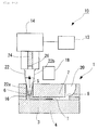
- Fig. 1 is a cross sectional view for illustrating a specimen material detection device using a sensor chip in accordance with the present invention.
- Fig. 2 is an arrow view diagram viewed from a direction of an arrow and taken along the line A-A of Fig. 1 .
- Fig. 3 is an arrow view diagram viewed from a direction of an arrow and taken along the line B-B of Fig. 2 .
- a symbol 10 represents a specimen material detection device 10 using a sensor chip 1 in accordance with the present invention.
- the specimen material detection device 10 is provided with the sensor chip 1.
- the sensor chip 1 is provided with a fine flow passage 2. Inside the fine flow passage 2, a detection region (a reaction field) 4 in a rectangular shape viewed from the top surface is disposed on the bottom surface in the fine flow passage 2 for instance. An antibody of a predetermined amount that reacts with a specific antigen is fixed to the detection region (the reaction field) 4.
- the sensor chip 1 is provided with a dielectric member 3 that configures a prism.
- a metallic thin film that is not shown is formed on a horizontal top surface of the dielectric member 3, and a detection region 4 is also formed.
- the sensor chip 1 is provided with a dielectric member 3 that configures a prism.
- a metallic thin film that is not shown is formed on a horizontal top surface of the dielectric member 3, and a detection region 4 is also formed in the present embodiment.
- a metallic thin film is formed on a substrate, a detection region 4 is formed, and a dielectric member that configures a prism is disposed on the under surface of a substrate so as to be fixed or attached detachably.
- the sensor chip 1 means a sensor chip that includes a prism or a sensor chip that does not include a prism.
- a shape of the detection region 4 is a rectangular shape viewed from the top surface.
- a shape of the detection region 4 can also be a wide variety of shapes such as a circular shape and an ellipse shape.
- the sensor chip 1 of the present embodiment is used for a surface plasmon measurement device such as an SPR device and an SPFS device for instance.
- the fine flow passage 2 is provided with a first inflow outflow hole 6 that is an inflow outflow hole that is configured to make a solution 16 inflow to and outflow from the fine flow passage 2 on an edge part of one side in a direction of the flow passage, and a second inflow outflow hole 8 that is an inflow outflow hole that is configured to make a solution 16 that has been flown from the first inflow outflow hole 6 inflow to and outflow from the fine flow passage 2 on an edge part of the other side in a direction of the flow passage of the fine flow passage 2.
- a mixing part 20 is connected to the side of a top surface of the second inflow outflow hole 8.
- the mixing part 20 is formed in a cross sectional shape that is larger than that of the second inflow outflow hole 8, such as a circular shape and a rectangular shape.
- a pipette 22 that has held the solution 16 is connected to the side of a top surface of the first inflow outflow hole 6.
- the pipette 22 is configured so as to be used attachably to and detachably from the first inflow outflow hole 6 of the fine flow passage 2.
- a diameter of a base end part 22b of the pipette 22 is larger than that of a leading end 22a of the pipette 22.
- a solution sending pump 14 is attached to the upper part of the pipette 22.
- the solution sending pump 14 is communicated with a control part 12.
- the solution 16 that has been held in the pipette 22 can be discharged to the fine flow passage 2 by an operation of a plunger 24 of the solution sending pump 14 via an air (an air damper) 26 that is a driving gas, or the solution 16 that has been stored in the fine flow passage 2 and a mixing part 20 can be sucked to the pipette 22.
- the mixing part 20 is provided with a cross sectional shape that is larger than that of the flow passage of the fine flow passage 2.
- a symbol 18 in Fig. 1 represents a light detection means such as a photomultiplier tube (PMT) and a CCD.
- PMT photomultiplier tube
- CCD CCD
- Figs. 4 to 9 are the schematic views for illustrating a flow of the solution 16 for the specimen material detection device 10 in accordance with the present invention.
- FIG. 4 to 9 indicate a solution sending direction of the solution 16.
- a symbol S represents an interfacial boundary surface on the side of a back end in a direction of a solution sending between the solution 16 and an air, that is, an air liquid interface
- a symbol T represents an interfacial boundary surface on the side of a front end in a direction of a solution sending between the solution 16 and an air, that is, an air liquid interface.
- Fig. 4 shows the state in which the pipette 22 that holds the solution 16 is mounted to the first inflow outflow hole 6 of the fine flow passage 2 and the solution sending pump 14 is attached to the pipette 22.
- the solution sending pump 14 further discharges the solution 16 that has been held in the pipette 22 from this state
- the most of the solution 16 in the pipette 22 is made inflow into the fine flow passage 2 via the first inflow outflow hole 6 and an air liquid interface S is located between the first inflow outflow hole 6 of the fine flow passage 2 and the detection region 4 as shown in Fig. 6-1 .
- the solution 16 that has passed over the detection region 4 is flown into the mixing part 20 via the second inflow outflow hole 8, and an air liquid interface T in the mixing part 20 moves upward.
- the solution sending pump 14 is then driven in order to suck the solution 16 in this state.
- a solution sending direction of the solution 16 is then reversed as shown by the arrow in Fig. 7-1 .
- the solution 16 in the mixing part 20 is then made inflow into the fine flow passage 2 via the second inflow outflow hole 8, passes over the detection region 4 again, and is made inflow into the pipette 22 via the first inflow outflow hole 6.
- An air liquid interface S in the pipette 22 moves upward, and an air liquid interface T in the fine flow passage 2 is located near the detection region 4 as shown in Fig. 8-1 .
- the solution sending pump 14 is then driven in order to discharge the solution 16 again in the state shown in Fig. 8-1 .
- a solution sending direction of the solution 16 is then reversed again.
- the solution 16 in the pipette 22 is then made inflow into the fine flow passage 2 via the first inflow outflow hole 6, and the solution 16 that has passed over the detection region 4 is made inflow into the mixing part 20 via the second inflow outflow hole 8 in the state shown in Fig. 6-1 .
- the states of Fig. 6-1 , Fig. 7-1 , Fig. 8-1 , and Fig. 6-1 are transferred in a repetitive manner by operating the discharge and the suction using the solution sending pump 14 in a repetitive manner, whereby the solution 16 passes over the detection region 4 in the fine flow passage 2 in a repetitive manner.
- a method of a solution sending can also be adopted for sending a solution in a state in which an interfacial boundary surface (the air liquid interface S) on the side of a back end in a direction of a solution sending between the solution 16 and an air and an interfacial boundary surface (the air liquid interface T) on the side of a front end in a direction of a solution sending between the solution 16 and an air are located in the pipette 22 and in the mixing part 20 on a constant basis.
- an interfacial boundary surface (the air liquid interface S) on the side of a back end in a direction of a solution sending between the solution 16 and an air is located in the pipette 22 on a constant basis.
- the solution 16 is made inflow into the fine flow passage 2 via the first inflow outflow hole 6 and an air liquid interface S is located near a leading end in the pipette 22 as shown in Fig. 6-2 .
- the solution 16 that has passed over the detection region 4 is flown into the mixing part 20 via the second inflow outflow hole 8, and an air liquid interface T in the mixing part 20 moves upward.
- an interfacial boundary surface (the air liquid interface S) on the side of a back end in a direction of a solution sending between the solution 16 and an air is located in the pipette 22 on a constant basis.
- an interfacial boundary surface (the air liquid interface T) on the side of a front end in a direction of a solution sending between the solution 16 and an air is located in the mixing part 20 on a constant basis.
- the solution sending pump 14 is then driven in order to suck the solution 16 in this state.
- a solution sending direction of the solution 16 is then reversed as shown by the arrow in Fig. 7-2 .
- the solution 16 in the mixing part 20 is then made inflow into the fine flow passage 2 via the second inflow outflow hole 8, passes over the detection region 4 again, and is made inflow into the pipette 22 via the first inflow outflow hole 6.
- An air liquid interface S in the pipette 22 then moves upward, and an air liquid interface T is located near the lower end in the mixing part 20 as shown in Fig. 8-2 .
- an interfacial boundary surface (the air liquid interface S) on the side of a back end in a direction of a solution sending between the solution 16 and an air is located in the pipette 22 on a constant basis.
- an interfacial boundary surface (the air liquid interface T) on the side of a front end in a direction of a solution sending between the solution 16 and an air is located in the mixing part 20 on a constant basis.
- the solution sending pump 14 is then driven in order to discharge the solution 16 again in the state shown in Fig. 8-2 .
- a solution sending direction of the solution 16 is then reversed again.
- the solution 16 in the pipette 22 is then made inflow into the fine flow passage 2 via the first inflow outflow hole 6, and the solution 16 that has passed over the detection region 4 is made inflow into the mixing part 20 via the second inflow outflow hole 8 in the state shown in Fig. 6-2 .
- the states of Fig. 6-2 , Fig. 7-2 , Fig. 8-2 , and Fig. 6-2 are transferred in a repetitive manner by operating the discharge and the suction using the solution sending pump 14 in a repetitive manner, whereby the solution 16 passes over the detection region 4 in the fine flow passage 2 in a repetitive manner.
- an interfacial boundary surface (the air liquid interface S) on the side of a back end in a direction of a solution sending between the solution 16 and an air and an interfacial boundary surface (the air liquid interface T) on the side of a front end in a direction of a solution sending between the solution 16 and an air are located in the pipette 22 or in the mixing part 20 on a constant basis.
- a solution back end 120 at the center part in a direction of a width of the first solution 104 in the fine flow passage 102 reaches the inflow outflow hole 108 at first, and the first solution 104 remains at the both ends in a direction of a width near a contact point of the inflow outflow hole 108 and the fine flow passage 102, thereby causing a residue of a solution.
- a shape of a flow passage has a deep relationship with a fluctuation of a measurement.
- the present invention is configured in such a manner that the relationship between the maximum width (a) of the first inflow outflow hole 6 and the width (b) of the fine flow passage 2 is a > b, where the maximum width (a) is the maximum length in a direction that is equivalent to a direction of a width of a flow passage.
- the present invention is configured in such a manner that an angle ⁇ that is formed between a wall surface 2a of the fine flow passage 2 and the tangent line A of the first inflow outflow hole 6 at a contact point 28 of the first inflow outflow hole 6 and the fine flow passage 2 is in the range of 90° ⁇ ⁇ ⁇ 135°.
- a cross sectional shape of the first inflow outflow hole 6 is a circular shape.
- a width (b) of the fine flow passage 2 is constant.
- a detection area region width (d) of a detection region (a reaction field) 4 is formed so as to be larger than the width (b) of the fine flow passage 2 as shown in Fig. 11-2 .
- the first solution 16 can be prevented from remaining at the both ends in a direction of a width near a contact point 28 of the first inflow outflow hole 6 and the fine flow passage 2, whereby a residue of a solution can be prevented, and an irregularity can be prevented from occurring in a concentration and a fluctuation of a signal can be prevented from occurring during a detection, whereby an inspection can be carried out in a precise manner.
- an angle ⁇ that is formed between a wall surface 2a of the fine flow passage 2 and the tangent line A of the first inflow outflow hole 6 is in the range of 90° ⁇ ⁇ ⁇ 135° as shown in Table 1, it can be found that a residual amount of a solution is small and a fluctuation of a signal can be prevented from occurring during a detection (a variation coefficient CV value is small).
- Table 1 shows the case in which an inspection has been carried out using a sample of 100 ml five times under each condition.
- an average flow rate is calculated by a time from a start of a movement of a solution by a solution sending to a stop of a movement of a solution and an amount of a solution that has been moved.
- an amount of a solution that has been moved can be calculated from an amount of a movement of a solution by the image analysis.
- a flow rate instrument can also be used.
- a time from a start of a movement of a solution to a stop of a movement of a solution can also be obtained by the image analysis for instance.
- a location of the detection region 4 in the fine flow passage 2 is set apart by a constant distance from the first inflow outflow hole 6 and a measurement is carried out at a location in which a flow of a solution 16 is stable.
- the relationship between the maximum width (a) of the first inflow outflow hole 6 and the width (b) of the fine flow passage 2 is a > b and a flow passage height is small as described above. Consequently, in the case in which a distance L is set to be long, a resistance of the flow passage becomes large. Therefore, in the case in which a resistance of the flow passage becomes large, a pressure that is applied during a solution sending becomes large. As a result, a leakage of a solution occurs from the first inflow outflow hole 6 or a junction part 28 of the first inflow outflow hole 6 and the fine flow passage 2.
- a movement of a plunger 24 and an amount of a solution that is sent do not keep pace with each other and a speed of the plunger 24 and a rate of a solution sending vary more greatly in the case in which a resistance in the fine flow passage 2 is larger.
- a desired amount of a solution cannot be sent, a sensitivity of a measurement is degraded, and a fluctuation of a measurement becomes larger.
- a distance L is too long from the aspect of the performance of a solution sending and a fluctuation of a measurement. Moreover, it is also not preferable that a distance L is too short from the aspect of a fluctuation of a measurement caused by a turbulence of a solution.
- a solution that flows in the flow passage is in the range of a laminar flow region, a turbulent flow does not occur in the flow passage, and a laminar flow causes a uniform flow. Consequently, a stagnation of a solution does not occur in the flow passage.
- the detection region in the flow passage is not provided with a disturbance of the index of refraction, and a fluctuation of a signal can be prevented from occurring during a detection, whereby an inspection can be carried out in a precise manner.
- a pressure of the solution sending that is applied to a flow passage is decided depending on a degree of viscosity of a solution and a speed of the solution sending to a certain shape of a flow passage.
- a pressure ( kPa resistance of the flow passage ⁇ flow rate / 60
- a solution in which a degree of viscosity at 20°C is in the range of mPa*s is sent at an average flow rate in the range of 1 to 5000 ⁇ l/min.
- variable A 8 ⁇ [(flow passage height h + flow passage width b) 2 ⁇ 10 3 / ⁇ (flow passage height h ⁇ flow passage width b) 3 ⁇ 60 ⁇ ].
- the units are ⁇ l/min for a flow rate, ⁇ m for a flow passage height, ⁇ m for a flow passage width, ⁇ m for a flow passage length, and mPa*s for a degree of viscosity.
- a distance L from an end part on a side of the flow passage of the first inflow outflow hole 6 to a center of the detection region 4 is set to be in the range of 1 to 50 mm.
- a distance L from an end part on a side of the flow passage of the first inflow outflow hole 6 to a center of the detection region 4 is set to be in the range of 1 to 50 mm as described above, a turbulent flow does not occur in the fine flow passage 2, and a laminar flow causes a uniform flow. Consequently, a stagnation of a solution 16 does not occur in the fine flow passage 2.
- the detection region in the fine flow passage 2 is not provided with a disturbance of the index of refraction, and a fluctuation of a signal can be prevented from occurring during a detection, whereby an inspection can be carried out in a precise manner.
- a pressure depends on a degree of viscosity of a solution
- a distance L is 60 mm and a degree of viscosity of a solution is larger than 0.001 kg/m*s
- a pressure is further increased and a leakage of a solution has the higher potential to occur. Consequently, it is preferable that a distance L is set to be in the range of 1 to 50 mm.
- the descriptions have been made for the relationship between the maximum width (a) of the first inflow outflow hole 6 and the width (b) of the fine flow passage 2 and a distance L from an end part on a side of the flow passage of the first inflow outflow hole 6 to a center of the detection region 4.
- the configuration similar to the above is set for the relationship between the maximum width (a) of the second inflow outflow hole 8 and the width (b) of the fine flow passage 2 and a distance L from an end part on a side of the flow passage of the second inflow outflow hole 8 to a center of the detection region 4.
- a value of L/b*h is set to be in the range of 10 to 500.
- a distance L from an end part on a side of the flow passage of the second inflow outflow hole 8 to a center of the detection region 4 is set to be in the range of 1 to 50 mm.
- the present invention is not restricted to the embodiments described above. While a specimen material detection device that is called the reciprocation type has been described as the specimen material detection device 10 in the above embodiments, the specimen material detection device 10 in accordance with the present invention is not restricted to the embodiments described above.
- the present invention can also be applied to any one of the specimen material detection devices of a one pass type not shown, a circulation type not shown, and a reciprocation type.
- an air (an air damper) 26 is used as a driving gas for the specimen material detection device 10 in accordance with the present embodiment
- an inert gas such as nitrogen and argon can also be used as a driving gas.
- the present invention can be applied to a sensor chip and a specimen material detection device using a sensor chip for a surface plasmon resonance device (hereafter referred to as an SPR device) using a phenomenon of a surface plasmon resonance (SPR: Surface Plasmon Resonance) and a surface plasmon-field enhanced fluorescence spectroscopy measurement device (hereafter referred to as an SPFS device) using a principle of a surface plasmon excitation enhanced fluorescence spectroscopy (SPFS: Surface Plasmon-field enhanced Fluorescence Spectroscopy) for the fields of a medical care and biotechnology for instance.
- SPR Surface Plasmon Resonance
- SPFS device surface plasmon-field enhanced fluorescence spectroscopy measurement device
- SPFS Surface Plasmon-field enhanced Fluorescence Spectroscopy
Abstract
Description
- The present invention relates to a sensor chip that is used in a specimen material detection device and a specimen material detection device using a sensor chip for a surface plasmon resonance device (hereafter referred to as an SPR device) using a phenomenon of a surface plasmon resonance (SPR: Surface Plasmon Resonance) and a surface plasmon-field enhanced fluorescence spectroscopy measurement device (hereafter referred to as an SPFS device) using a principle of a surface plasmon excitation enhanced fluorescence spectroscopy (SPFS: Surface Plasmon-field enhanced Fluorescence Spectroscopy) for the fields of a medical care and biotechnology for instance.
- In the case in which a detection of an extremely fine substance is carried out, a wide variety of specimen material detection device has been used for enabling an inspection of such a substance by putting a physical phenomenon of a substance to practical use from the past.
- As one of such specimen material detection devices, there can be mentioned for instance an SPR device in which a phenomenon for obtaining a high optical output by a resonance of an electron and a light in a minute region of a nanometer level or the like (a surface plasmon resonance (SPR: Surface Plasmon Resonance) phenomenon) is put to practical use and an extremely fine analyte in a biological body is detected for instance.
- As one of such specimen material detection devices, there also can be mentioned for instance an SPFS device in which the analyte detection can be carried out with a higher degree of accuracy as compared with the SPR device based on a principle of a surface plasmon excitation enhanced fluorescence spectroscopy (SPFS) for putting a surface plasmon resonance phenomenon to practical use.
- For the surface plasmon excitation enhanced fluorescence spectroscopy (SPFS), under the condition of the attenuated total reflectance (ATR) of an excitation light such as a laser light that has been applied from the light source on a surface of a metallic thin film, by generating a surface plasmon light (a crude density wave) on a surface of a metallic thin film, a photon amount that is included in an excitation light that has been applied from the light source is increased by several ten times to several hundred times to obtain an electric field enhancement effect of a surface plasmon light.
- By the electric field enhancement effect, a fluorescence substance that has been coupled (labeled) with an analyte that has been captured near a surface of a metallic thin film is excited in an efficient manner. By observing the fluorescence, an analyte of an infinitesimal quantity and/or an extremely low concentration is detected in the above method.
- For such a specimen material detection device such as an SPR device and an SPFS device, a specimen material solution that contains an analyte (antigen) that is a detection target is prepared in advance, the specimen material solution is sent to a fine flow passage, and an analyte (antigen) is captured with a ligand (antibody) that is fixed to a detection region (a reaction field) that is disposed in the fine flow passage.
- For such a specimen material detection device, a solution sending of a ligand solution, a specimen material solution, and a cleaning solution is carried out in a fine flow passage by ordinary.
- In this case, there can be mentioned for instance a specimen material detection device that is called a circulation type in which a specimen material solution is circulated and passes through a detection region in a repetitive manner and a system that is called a reciprocation type in which a specimen material solution is reciprocated and passes through a detection region in a repetitive manner in addition to a system that is called a one pass type in which a specimen material solution passes through a detection region only one time.
- For instance, the Patent Literature 1 (Japanese Patent Application Laid-Open Publication No.
2006-90985 - More specifically, the measurement device that is disclosed in the
Patent Literature 1 is provided with a first sending and discharge means such as a pipette capable of performing a discharge of an analyte solution to and the suction of an analyte solution from a flow passage. In the description of thePatent Literature 1, by sending an analyte solution to a sensor face by the discharge and then carrying out a reverse flow by a suction of the analyte solution by using the first sending and discharge means, an analyte solution is reciprocated on a sensor face at least once, and the analyte solution is sent to the sensor face again after that. - Japanese Patent Application Laid-Open Publication No.
2006-90985 - Any one of the specimen material detection devices of a one pass type, a circulation type, and a reciprocation type as described above has the following problem.
-
Fig. 23 is a schematic view for showing a specimenmaterial detection device 100 of a reciprocation type for instance. - As shown in
Fig. 23 , the specimenmaterial detection device 100 is provided with afine flow passage 102 and asolution sending pump 106 that is configured to send asolution 104 such as a ligand solution, a specimen material solution, and a cleaning solution. - As shown in
Figs. 23 and24 moreover, thefine flow passage 102 is provided with aninflow outflow hole 108 that is an inflow outflow hole that is configured to make asolution 104 inflow to and outflow from thefine flow passage 102 on an edge part of one side in a direction of the flow passage, and anoutlet hole 110 that is an outlet of asolution 104 that outflows from theinflow outflow hole 108 on an edge part of the other side in a direction of the flow passage. - A detection region (a reaction field) 112 to which an antibody (a ligand) that reacts with a specific antigen is fixed is disposed on a bottom surface in the
fine flow passage 102. In the case in which asolution 104 that includes a specific antigen (analyte) is sent by asolution sending pump 106, thesolution 104 passes through thedetection region 112 of thefine flow passage 102 in a repetitive manner. - As shown in
Fig. 23 moreover, apipette 114 that has held thesolution 104 is connected to the side of a top surface of theinflow outflow hole 108. Thepipette 114 is configured so as to be used attachably to and detachably from theinflow outflow hole 108 of thefine flow passage 102. - A
solution sending pump 106 is attached to the upper part of thepipette 114. Thesolution sending pump 106 is communicated with acontrol part 116. By the control of thecontrol part 116, thesolution 104 that has been held in thepipette 114 can be discharged to thefine flow passage 102, or thesolution 104 that has been stored in thefine flow passage 102 and amixing part 118 can be sucked to thepipette 114. - For the specimen
material detection device 100 that is configured as described above, after afirst solution 104 such as a specimen material solution is made inflow from theinflow outflow hole 108 and thefirst solution 104 is removed from theinflow outflow hole 108 for instance, another second solution is made inflow into a flow passage, or after afirst solution 104 is made inflow into thefine flow passage 102, another second solution is made inflow into a flow passage via a driving gas such as an air. The above described cases are provided with the following problem. - In other words, as shown in
Fig. 24 , in the case in which a width b of thefine flow passage 102 that comes into contact with theinflow outflow hole 108 is equal to or larger than the maximum width a of the inflow outflow hole 108 (a diameter a of theinflow outflow hole 108 in this case), the following problem takes its rise. - In this case, in the case in which the
first solution 104 is discharged from theinflow outflow hole 108, a flow rate is low at a wall surface of thefine flow passage 102 and a flow rate is high at the center part in a direction of a width of thefirst solution 104 in thefine flow passage 102 unfortunately. Consequently, as shown inFig. 25 , a solution backend 120 at the center part in a direction of a width of thefirst solution 104 in thefine flow passage 102 reaches theinflow outflow hole 108 at first, and thefirst solution 104 remains at the both ends in a direction of a width near a contact point of theinflow outflow hole 108 and thefine flow passage 102, thereby causing a residue of a solution. - In particular, in the case of a sandwich assay in which a cleaning solution, a specimen material solution, a cleaning solution, and a reaction test reagent are made inflow in this order into the
fine flow passage 102, in the case in which the previous solution remains, the next test reagent is diluted. As a result, an irregularity occurs in a concentration and a fluctuation of a signal occurs during a detection, whereby the detection accuracy is deteriorated. - Consequently, for a mechanism that is configured to carry out an assay in a flow passage with a minute sample as described above, a shape of a flow passage has a deep relationship with a fluctuation of a measurement.
- For such a problem, any one of the specimen material detection devices of a one pass type, a circulation type, and a reciprocation type of a conventional configuration has a similar problem.
- On the other hand, for the
Patent Literature 1, the maximum width (diameter) of the inflow outflow hole and a width of a flow passage are equivalent to each other, and the maximum width (diameter) of the inflow outflow hole and a width of a flow passage are not considered, whereby it is clarified that the above described problem occurs unfortunately. - The present invention was made in consideration of such a condition, and an object of the present invention is to provide a sensor chip that is used in a specimen material detection device and a specimen material detection device using a sensor chip, in which the first solution can be prevented from remaining at the both ends in a direction of a width near a contact point of the inflow outflow hole and the fine flow passage, whereby a residue of a solution can be prevented, and an irregularity can be prevented from occurring in a concentration and a fluctuation of a signal can be prevented from occurring during a detection, whereby an inspection can be carried out in a precise manner, in the case in which after a first solution such as a specimen material solution is made inflow from the inflow outflow hole and the first solution is removed from the inflow outflow hole, a second solution is made inflow into a flow passage, or after a first solution is made inflow into the flow passage, a second solution is made inflow into a flow passage via an air that is a driving gas.
- The present invention was made in order to solve the problems of the conventional art described above and achieve the purpose.
- A sensor chip that is used in a specimen material detection device in accordance with the present invention is characterized by comprising:
- a flow passage that is provided with a detection region; and
- an inflow outflow hole that is connected to an edge part of one side of the flow passage and that is configured to be able to make a solution inflow to and outflow from the flow passage, wherein:
- after a first solution is made inflow from the inflow outflow hole and the first solution is removed from the flow passage, a second solution is made inflow into the flow passage from the inflow outflow hole, or after a first solution is made inflow into the flow passage from the inflow outflow hole, a second solution is made inflow into a flow passage from the inflow outflow hole via a driving gas, and
- the sensor chip is configured in such a manner that the relationship between the maximum width (a) of the inflow outflow hole and the width (b) of the flow passage is a > b, and an angle θ that is formed between a wall surface of the flow passage and the tangent line of the inflow outflow hole at a contact point of the inflow outflow hole and the flow passage is in the range of 90° ≤ θ ≤ 135°.
- As described above, the present invention is configured in such a manner that the relationship between the maximum width (a) of the inflow outflow hole and the width (b) of the flow passage is a > b, and an angle θ that is formed between a wall surface of the flow passage and the tangent line of the inflow outflow hole at a contact point of the inflow outflow hole and the flow passage is in the range of 90° ≤ θ ≤ 135°.
- By this configuration, in the case in which after a first solution such as a specimen material solution is made inflow from the inflow outflow hole and the first solution is removed from the inflow outflow hole, a second solution is made inflow into a flow passage, or after a first solution is made inflow into the flow passage, a second solution is made inflow into a flow passage via an air that is a driving gas for instance, as shown in Table 1 that will be described later, the first solution can be prevented from remaining at the both ends in a direction of a width near a contact point of the inflow outflow hole and the fine flow passage, whereby a residue of a solution can be prevented, and an irregularity can be prevented from occurring in a concentration and a fluctuation of a signal can be prevented from occurring during a detection, whereby an inspection can be carried out in a precise manner.
- The sensor chip in accordance with the present invention is characterized in that:
- for a system in which a distance L from an end part on a side of the flow passage of the inflow outflow hole to a center of the detection region is at least 1 mm, and a solution in which a degree of viscosity at 20°C is in the range of 1 to 3 mPa*s is sent at an average flow rate in the range of 1 to 5000 µl/min,

where the variable A = 8 × [(flow passage height h + flow passage width b)2 × 10³ / {(flow passage height h × flow passage width b)3 × 60}], and - the units are µl/min for a flow rate, µm for a flow passage height, µm for a flow passage width, µm for a flow passage length, and mPa*s for a degree of viscosity.
- Here, an average flow rate is calculated by a time from a start of a movement of a solution by a solution sending to a stop of a movement of a solution and an amount of a solution that has been moved. In the case in which a cross sectional area of a flow passage is constant, "an amount of a solution that has been moved" can be calculated from an amount of a movement of a solution by the image analysis. Moreover, a flow rate instrument can also be used. Furthermore, "a time from a start of a movement of a solution to a stop of a movement of a solution" can also be obtained by the image analysis for instance.
- In other words, in the case in which a distance L from an end part on a side of the flow passage of the inflow outflow hole to a center of the detection region is too short for the flow passage that comes into contact with the inflow outflow hole, a flow of a solution that has just flown from the inflow outflow hole is turbulent. In addition, in the case in which a solution that is measured stagnates, a disturbance occurs for the index of refraction. Consequently, for the SPR device and the SPFS device in which the index of refraction has a huge effect on the accuracy of an inspection, the large variations have a huge effect on the accuracy of a measurement in the case in which a measurement is carried out.
- Consequently, it is necessary that a location of the detection region in the flow passage is set apart by a constant distance from the inflow outflow hole and a measurement is carried out at a location in which a flow of a solution is stable.
- However, even in the case in which a distance L from an end part on a side of the flow passage of the inflow outflow hole to a center of the detection region is too long, the configuration creates an adverse result.
- In other words, the relationship between the maximum width (a) of the inflow outflow hole and the width (b) of the flow passage is a > b and a flow passage height is small as described above. Consequently, in the case in which a distance L is set to be long, a resistance of the flow passage becomes large. Therefore, in the case in which a resistance of the flow passage becomes large, a pressure that is applied during a solution sending becomes large. As a result, a leakage of a solution occurs from the inflow outflow hole or a junction part of the inflow outflow hole and the flow passage.
- In particular, for the configuration of a solution sending that is provided with an air damper in a solution sending system, in addition to a leakage of a solution, a movement of a plunger and an amount of a solution that is sent do not keep pace with each other and a speed of a plunger and a rate of a solution sending vary more greatly in the case in which a resistance in the flow passage is larger. As a result, a desired amount of a solution cannot be sent, a sensitivity of a measurement is degraded, and a fluctuation of a measurement becomes larger.
- Consequently, it is not preferable that a distance L is too long from the aspect of the performance of a solution sending and a fluctuation of a measurement. Moreover, it is also not preferable that a distance L is too short from the aspect of a fluctuation of a measurement caused by a turbulence of a solution. As a result, like the configuration of the present invention, it is preferable that:
- for a system in which a distance L from an end part on a side of the flow passage of the inflow outflow hole to a center of the detection region is at least 1 mm, and a solution in which a degree of viscosity at 20°C is in the range of 1 to 3 mPa*s is sent at an average flow rate in the range of 1 to 5000 µl/min,

where the variable A = 8 × [(flow passage height h + flow passage width b)2 × 10³ / {(flow passage height h × flow passage width b)3 × 60}], and - the units are µl/min for a flow rate, µm for a flow passage height, µm for a flow passage width, µm for a flow passage length, and mPa*s for a degree of viscosity.
- By this configuration, as shown in Table 2 that will be described later and
Fig. 12 , a solution that flows in the flow passage is in the range of a laminar flow region, a turbulent flow does not occur in the flow passage, and a laminar flow causes a uniform flow. Consequently, a stagnation of a solution does not occur in the flow passage. As a result, the detection region in the flow passage is not provided with a disturbance of the index of refraction, and a fluctuation of a signal can be prevented from occurring during a detection, whereby an inspection can be carried out in a precise manner. - The sensor chip in accordance with the present invention is characterized in that a distance L from an end part on a side of the flow passage of the inflow outflow hole to a center of the detection region is set to be in the range of 1 to 50 mm.
- In the case in which a distance L from an end part on a side of the flow passage of the inflow outflow hole to a center of the detection region is set to be in the range of 1 to 50 mm as described above, a turbulent flow does not occur in the flow passage, and a laminar flow causes a uniform flow. Consequently, a stagnation of a solution does not occur in the flow passage. As a result, the detection region in the flow passage is not provided with a disturbance of the index of refraction, and a fluctuation of a signal can be prevented from occurring during a detection, whereby an inspection can be carried out in a precise manner.
- The sensor chip in accordance with the present invention is characterized in that a solution that is made inflow into the flow passage is reciprocated and passes through the detection region.
- For a specimen material detection device that is called a reciprocation type in which a solution that is made inflow into the flow passage is reciprocated and passes through the detection region, the first solution can be prevented from remaining at the both ends in a direction of a width near a contact point of the inflow outflow hole and the fine flow passage, whereby a residue of a solution can be prevented, as shown in Table 1 that will be described later, and an irregularity can be prevented from occurring in a concentration and a fluctuation of a signal can be prevented from occurring during a detection, whereby an inspection can be carried out in a precise manner.
- The sensor chip in accordance with the present invention is characterized in that:
- a second inflow outflow hole is connected to the other end side of the flow passage,
- the relationship between the maximum width (a) of the second inflow outflow hole and the width (b) of the flow passage is a > b, and
- an angle θ that is formed between a wall surface of the flow passage and the tangent line of the second inflow outflow hole at a contact point of the second inflow outflow hole and the flow passage is in the range of 90° ≤ θ ≤ 135°.
- By this configuration, the first solution can be prevented from remaining at the both ends in a direction of a width near a contact point of the second inflow outflow hole and the fine flow passage, whereby a residue of a solution can be prevented, as shown in Table 1 that will be described later, and an irregularity can be prevented from occurring in a concentration and a fluctuation of a signal can be prevented from occurring during a detection, whereby an inspection can be carried out in a precise manner.
- The sensor chip in accordance with the present invention is characterized in that:
- for a system in which a distance L from an end part on a side of the flow passage of the second inflow outflow hole to a center of the detection region is at least 1 mm for the second inflow outflow hole, and a solution in which a degree of viscosity at 20°C is in the range of 1 to 3 mPa*s is sent at an average flow rate in the range of 1 to 5000 µl/min,

- where the variable A = 8 × [(flow passage height h + flow passage width b)2 × 10³ / {(flow passage height h × flow passage width b)3 × 60}], and
- the units are µl/min for a flow rate, µm for a flow passage height, µm for a flow passage width, µm for a flow passage length, and mPa*s for a degree of viscosity.
- By this configuration, a solution that flows in the flow passage is in the range of a laminar flow region, a turbulent flow does not occur in the flow passage, and a laminar flow causes a uniform flow. Consequently, a stagnation of a solution does not occur in the flow passage. As a result, the detection region in the flow passage is not provided with a disturbance of the index of refraction, and a fluctuation of a signal can be prevented from occurring during a detection, whereby an inspection can be carried out in a precise manner.
- The sensor chip in accordance with the present invention is characterized in that a distance L from an end part on a side of the flow passage of the second inflow outflow hole to a center of the detection region is set to be in the range of 1 to 50 mm.
- In the case in which a distance L from an end part on a side of the flow passage of the second inflow outflow hole to a center of the detection region is set to be in the range of 1 to 50 mm as described above, a turbulent flow does not occur in the flow passage, and a laminar flow causes a uniform flow. Consequently, a stagnation of a solution does not occur in the flow passage. As a result, the detection region in the flow passage is not provided with a disturbance of the index of refraction, and a fluctuation of a signal can be prevented from occurring during a detection, whereby an inspection can be carried out in a precise manner.
- The sensor chip in accordance with the present invention is characterized by further comprising a mixing part at the second inflow outflow hole in such a manner that the mixing part is configured to store a solution that has passed through the detection region of the flow passage on a temporary basis and to stir the solution that has been stored.
- For any one of the specimen material detection devices of a circulation type and a reciprocation type in which a specimen material solution passes through a reaction field of the fine flow passage in a repetitive manner, in the case in which the specimen material detection device is provided with a mixing part, a reaction efficiency can be prevented from being degraded, and a solution can be sent in a repetitive manner.
- A specimen material detection device in accordance with the present invention is characterized by comprising a sensor chip as defined in any one of the above descriptions.
- By this configuration, the first solution can be prevented from remaining at the both ends in a direction of a width near a contact point of the inflow outflow hole and the fine flow passage, whereby a residue of a solution can be prevented, as shown in Table 1 that will be described later, and an irregularity can be prevented from occurring in a concentration and a fluctuation of a signal can be prevented from occurring during a detection, whereby an inspection can be carried out in a precise manner.
- The specimen material detection device in accordance with the present invention is characterized in that the specimen material detection device is a surface plasmon resonance device (an SPR device) or a surface plasmon field enhanced fluorescence spectroscopic measurement device (an SPFS device).
- In the case in which the specimen material detection device is a surface plasmon resonance device (an SPR device) or a surface plasmon field enhanced fluorescence spectroscopic measurement device (an SPFS device) as described above, the specimen material detection device is suitable as a detection device of an extremely fine analyte in particular, a reaction efficiency can be improved as compared with a conventional SPR device or a conventional SPFS device, and an SPR device and an SPFS device that are provided with a small variation among individual pieces and a high degree of precision can be implemented.
- The present invention is configured in such a manner that the relationship between the maximum width (a) of the inflow outflow hole and the width (b) of the flow passage is a > b, and an angle θ that is formed between a wall surface of the flow passage and the tangent line of the inflow outflow hole at a contact point of the inflow outflow hole and the flow passage is in the range of 90° ≤ θ ≤ 135°.
- By this configuration, in the case in which after a first solution such as a specimen material solution is made inflow from the inflow outflow hole into the flow passage and the first solution is removed from the flow passage, a second solution is made inflow from the inflow outflow hole into a flow passage, or after a first solution is made inflow from the inflow outflow hole into the flow passage, a second solution is made inflow from the inflow outflow hole into a flow passage via an air that is a driving gas for instance, the first solution can be prevented from remaining at the both ends in a direction of a width near a contact point of the inflow outflow hole and the fine flow passage, whereby a residue of a solution can be prevented, as shown in Table 1 that will be described later, and an irregularity can be prevented from occurring in a concentration and a fluctuation of a signal can be prevented from occurring during a detection, whereby an inspection can be carried out in a precise manner.
- The present invention is configured in such a manner that:
- for a system in which a distance L from an end part on a side of the flow passage of the inflow outflow hole to a center of the detection region is at least 1 mm, and a solution in which a degree of viscosity at 20°C is in the range of 1 to 3 mPa*s is sent at an average flow rate in the range of 1 to 5000 µl/min,

where the variable A = 8 × [(flow passage height h + flow passage width b)2 × 10³ / {(flow passage height h × flow passage width b)3 × 60}], and - the units are µl/min for a flow rate, µm for a flow passage height, µm for a flow passage width, µm for a flow passage length, and mPa*s for a degree of viscosity.
- As a result, by this configuration, a solution that flows in the flow passage is in the range of a laminar flow region, a turbulent flow does not occur in the flow passage, and a laminar flow causes a uniform flow. Consequently, a stagnation of a solution does not occur in the flow passage. As a result, the detection region in the flow passage is not provided with a disturbance of the index of refraction, and a fluctuation of a signal can be prevented from occurring during a detection, whereby an inspection can be carried out in a precise manner.
-
- [
Fig. 1 ]
Fig. 1 is a cross sectional view for illustrating a specimen material detection device using a sensor chip in accordance with the present invention. - [
Fig. 2 ]
Fig. 2 is an arrow view diagram viewed from a direction of an arrow and taken along the line A-A ofFig. 1 . - [
Fig. 3 ]
Fig. 3 is an arrow view diagram viewed from a direction of an arrow and taken along the line B-B ofFig. 2 . - [
Fig. 4 ]
Fig. 4 is a schematic view for illustrating a flow of asolution 16 for a specimenmaterial detection device 10 in accordance with the present invention. - [
Fig. 5-1 ]
Fig. 5-1 is a schematic view for illustrating a flow of asolution 16 for a specimenmaterial detection device 10 in accordance with the present invention. - [
Fig. 5-2 ]
Fig. 5-2 is a schematic view for illustrating a flow of asolution 16 for a specimenmaterial detection device 10 in accordance with the present invention. - [
Fig. 6-1 ]
Fig. 6-1 is a schematic view for illustrating a flow of asolution 16 for a specimenmaterial detection device 10 in accordance with the present invention. - [
Fig. 6-2 ]
Fig. 6-2 is a schematic view for illustrating a flow of asolution 16 for a specimenmaterial detection device 10 in accordance with the present invention. - [
Fig. 7-1 ]
Fig. 7-1 is a schematic view for illustrating a flow of asolution 16 for a specimenmaterial detection device 10 in accordance with the present invention. - [
Fig. 7-2 ]
Fig. 7-2 is a schematic view for illustrating a flow of asolution 16 for a specimenmaterial detection device 10 in accordance with the present invention. - [
Fig. 8-1 ]
Fig. 8-1 is a schematic view for illustrating a flow of asolution 16 for a specimenmaterial detection device 10 in accordance with the present invention. - [
Fig. 8-2 ]
Fig. 8-2 is a schematic view for illustrating a flow of asolution 16 for a specimenmaterial detection device 10 in accordance with the present invention. - [
Fig. 9 ]
Fig. 9 is a schematic view for illustrating a flow of asolution 16 for a specimenmaterial detection device 10 in accordance with the present invention. - [
Fig. 10 ]
Fig. 10 is a partially enlarged view similar toFig. 2 . - [
Fig. 11-1 ]
Fig. 11-1 is a partially enlarged view similar toFig. 2 . - [
Fig. 11-2 ]
Fig. 11-2 is a partially enlarged view similar toFig. 2 . - [
Fig. 12 ]
Fig. 12 is a graph for showing the relationship among the dimension of a flow passage, the maximum Reynolds number, a laminar flow region, and a turbulent flow region. - [
Fig. 13 ]
Fig. 13 is a graph for showing the relationship between a length of a flow passage and a pressure of the solution sending. - [
Fig. 14 ]
Fig. 14 is a graph for showing the relationship between a length of a flow passage and a pressure of the solution sending. - [
Fig. 15 ]
Fig. 15 is a graph for showing the relationship between a length of a flow passage and a pressure of the solution sending. - [
Fig. 16 ]
Fig. 16 is a graph for showing the relationship between a length of a flow passage and a pressure of the solution sending. - [
Fig. 17 ]
Fig. 17 is a graph for showing the relationship between a length of a flow passage and a pressure of the solution sending. - [
Fig. 18 ]
Fig. 18 is a graph for showing the relationship between a length of a flow passage and a pressure of the solution sending. - [
Fig. 19 ]
Fig. 19 is a graph for showing the relationship between a length of a flow passage and a pressure of the solution sending. - [
Fig. 20 ]
Fig. 20 is a graph for showing the relationship between a length of a flow passage and a pressure of the solution sending. - [
Fig. 21 ]
Fig. 21 is a graph for showing the relationship between a length of a flow passage and a pressure of the solution sending. - [
Fig. 22 ]
Fig. 22 is a graph for showing the relationship between a length of a flow passage and a pressure of the solution sending. - [
Fig. 23 ]
Fig. 23 is a cross sectional view for illustrating a conventional specimen material detection device. - [
Fig. 24 ]
Fig. 24 is an arrow view diagram viewed from a direction of an arrow and taken along the line A-A ofFig. 23 for illustrating a flow of a solution. - [
Fig. 25 ]
Fig. 25 is an arrow view diagram viewed from a direction of an arrow and taken along the line A-A ofFig. 23 for illustrating a flow of a solution. - An embodiment (an example) of the present invention will be described below in detail with reference to the drawings.
-
Fig. 1 is a cross sectional view for illustrating a specimen material detection device using a sensor chip in accordance with the present invention.Fig. 2 is an arrow view diagram viewed from a direction of an arrow and taken along the line A-A ofFig. 1 .Fig. 3 is an arrow view diagram viewed from a direction of an arrow and taken along the line B-B ofFig. 2 . - As shown in
Fig. 1 , asymbol 10 represents a specimenmaterial detection device 10 using asensor chip 1 in accordance with the present invention. The specimenmaterial detection device 10 is provided with thesensor chip 1. Thesensor chip 1 is provided with afine flow passage 2. Inside thefine flow passage 2, a detection region (a reaction field) 4 in a rectangular shape viewed from the top surface is disposed on the bottom surface in thefine flow passage 2 for instance. An antibody of a predetermined amount that reacts with a specific antigen is fixed to the detection region (the reaction field) 4. - The
sensor chip 1 is provided with adielectric member 3 that configures a prism. In addition, a metallic thin film that is not shown is formed on a horizontal top surface of thedielectric member 3, and adetection region 4 is also formed. - The
sensor chip 1 is provided with adielectric member 3 that configures a prism. In addition, a metallic thin film that is not shown is formed on a horizontal top surface of thedielectric member 3, and adetection region 4 is also formed in the present embodiment. However, although it is not shown, it is also possible that a metallic thin film is formed on a substrate, adetection region 4 is formed, and a dielectric member that configures a prism is disposed on the under surface of a substrate so as to be fixed or attached detachably. In this case, thesensor chip 1 means a sensor chip that includes a prism or a sensor chip that does not include a prism. - In the case of the present embodiment, a shape of the
detection region 4 is a rectangular shape viewed from the top surface. However, a shape of thedetection region 4 can also be a wide variety of shapes such as a circular shape and an ellipse shape. - The
sensor chip 1 of the present embodiment is used for a surface plasmon measurement device such as an SPR device and an SPFS device for instance. - As shown in
Fig. 2 , thefine flow passage 2 is provided with a firstinflow outflow hole 6 that is an inflow outflow hole that is configured to make asolution 16 inflow to and outflow from thefine flow passage 2 on an edge part of one side in a direction of the flow passage, and a secondinflow outflow hole 8 that is an inflow outflow hole that is configured to make asolution 16 that has been flown from the firstinflow outflow hole 6 inflow to and outflow from thefine flow passage 2 on an edge part of the other side in a direction of the flow passage of thefine flow passage 2. - As shown in
Fig. 1 , a mixingpart 20 is connected to the side of a top surface of the secondinflow outflow hole 8. The mixingpart 20 is formed in a cross sectional shape that is larger than that of the secondinflow outflow hole 8, such as a circular shape and a rectangular shape. - As shown in
Fig. 1 moreover, apipette 22 that has held thesolution 16 is connected to the side of a top surface of the firstinflow outflow hole 6. Thepipette 22 is configured so as to be used attachably to and detachably from the firstinflow outflow hole 6 of thefine flow passage 2. A diameter of abase end part 22b of thepipette 22 is larger than that of aleading end 22a of thepipette 22. - A
solution sending pump 14 is attached to the upper part of thepipette 22. Thesolution sending pump 14 is communicated with acontrol part 12. In accordance with a command from thecontrol part 12, thesolution 16 that has been held in thepipette 22 can be discharged to thefine flow passage 2 by an operation of aplunger 24 of thesolution sending pump 14 via an air (an air damper) 26 that is a driving gas, or thesolution 16 that has been stored in thefine flow passage 2 and a mixingpart 20 can be sucked to thepipette 22. - By this configuration, in the case in which a solution (a specimen material solution) 16 that includes a specific antigen (analyte) is sent by the
solution sending pump 14, thesolution 16 passes through thedetection region 4 of thefine flow passage 2 in a repetitive manner. - The mixing
part 20 is provided with a cross sectional shape that is larger than that of the flow passage of thefine flow passage 2. By this configuration, in the case in which thesolution 16 is made inflow into the mixingpart 20, a flow of thesolution 16 that has been flowing in a laminar flow state becomes turbulent, and thesolution 16 that has been stored in the mixingpart 20 is stirred. - As a result, even in the case in which the
solution 16 passes over thedetection region 4 in a repetitive manner, only the same layer does not come into contact with thedetection region 4, and most of thesolution 16 makes a contribution to a reaction at thedetection region 4. Moreover, for thepipette 22, thesolution 16 that has been stored is also stirred similarly. - A
symbol 18 inFig. 1 represents a light detection means such as a photomultiplier tube (PMT) and a CCD. - An example of a flowing operation of the
solution 16 for the specimenmaterial detection device 10 that is configured as described above will be described with reference toFigs. 4 to 9 . -
Figs. 4 to 9 are the schematic views for illustrating a flow of thesolution 16 for the specimenmaterial detection device 10 in accordance with the present invention. - The arrows of
Figs. 4 to 9 indicate a solution sending direction of thesolution 16. A symbol S represents an interfacial boundary surface on the side of a back end in a direction of a solution sending between thesolution 16 and an air, that is, an air liquid interface, and a symbol T represents an interfacial boundary surface on the side of a front end in a direction of a solution sending between thesolution 16 and an air, that is, an air liquid interface. -
Fig. 4 shows the state in which thepipette 22 that holds thesolution 16 is mounted to the firstinflow outflow hole 6 of thefine flow passage 2 and thesolution sending pump 14 is attached to thepipette 22. - In the case in which the
solution sending pump 14 is driven and thesolution 16 that has been held in thepipette 22 is discharged as shown by the arrow in the state shown inFig. 4 , thesolution 16 is made inflow into thefine flow passage 2 via the firstinflow outflow hole 6 and a part of thesolution 16 passes over thedetection region 4 as shown inFig. 5-1 . - In the case in which the
solution sending pump 14 further discharges thesolution 16 that has been held in thepipette 22 from this state, the most of thesolution 16 in thepipette 22 is made inflow into thefine flow passage 2 via the firstinflow outflow hole 6 and an air liquid interface S is located between the firstinflow outflow hole 6 of thefine flow passage 2 and thedetection region 4 as shown inFig. 6-1 . In addition, thesolution 16 that has passed over thedetection region 4 is flown into the mixingpart 20 via the secondinflow outflow hole 8, and an air liquid interface T in the mixingpart 20 moves upward. - The
solution sending pump 14 is then driven in order to suck thesolution 16 in this state. By this operation, a solution sending direction of thesolution 16 is then reversed as shown by the arrow inFig. 7-1 . Thesolution 16 in the mixingpart 20 is then made inflow into thefine flow passage 2 via the secondinflow outflow hole 8, passes over thedetection region 4 again, and is made inflow into thepipette 22 via the firstinflow outflow hole 6. An air liquid interface S in thepipette 22 moves upward, and an air liquid interface T in thefine flow passage 2 is located near thedetection region 4 as shown inFig. 8-1 . - The
solution sending pump 14 is then driven in order to discharge thesolution 16 again in the state shown inFig. 8-1 . By this operation, a solution sending direction of thesolution 16 is then reversed again. Thesolution 16 in thepipette 22 is then made inflow into thefine flow passage 2 via the firstinflow outflow hole 6, and thesolution 16 that has passed over thedetection region 4 is made inflow into the mixingpart 20 via the secondinflow outflow hole 8 in the state shown inFig. 6-1 . - In the case in which the
solution 16 is recovered, after thesolution sending pump 14 performs a suction of thesolution 16 to the state shown inFig. 9 , thepipette 22 that holds thesolution 16 can be detached. - For the specimen
material detection device 10 in accordance with the present embodiment as described above, the states ofFig. 6-1 ,Fig. 7-1 ,Fig. 8-1 , andFig. 6-1 are transferred in a repetitive manner by operating the discharge and the suction using thesolution sending pump 14 in a repetitive manner, whereby thesolution 16 passes over thedetection region 4 in thefine flow passage 2 in a repetitive manner. - In addition to the method of a solution sending for the
solution 16 for the specimenmaterial detection device 10 as described above, the following method of a solution sending can also be carried out as shown inFigs. 5-2 to 8-2 . - In other words, a method of a solution sending can also be adopted for sending a solution in a state in which an interfacial boundary surface (the air liquid interface S) on the side of a back end in a direction of a solution sending between the
solution 16 and an air and an interfacial boundary surface (the air liquid interface T) on the side of a front end in a direction of a solution sending between thesolution 16 and an air are located in thepipette 22 and in the mixingpart 20 on a constant basis. - This is because an accurate measurement cannot be carried out since an air bubble is generated when an air liquid interface passes through a region that becomes narrow in the case in which a solution that includes a protein or a surface activating agent is sent.
- More specifically, it is preferable that the following method of a solution sending is carried out.
- In the case in which the
solution sending pump 14 is driven and thesolution 16 that has been held in thepipette 22 is discharged as shown by the arrow in the state shown inFig. 4 , thesolution 16 is made inflow into thefine flow passage 2 via the firstinflow outflow hole 6 and a part of thesolution 16 passes over thedetection region 4 as shown inFig. 5-2 . - In this case as shown in
Fig. 5-2 , an interfacial boundary surface (the air liquid interface S) on the side of a back end in a direction of a solution sending between thesolution 16 and an air is located in thepipette 22 on a constant basis. - In the case in which the
solution sending pump 14 further discharges thesolution 16 that has been held in thepipette 22 from this state, thesolution 16 is made inflow into thefine flow passage 2 via the firstinflow outflow hole 6 and an air liquid interface S is located near a leading end in thepipette 22 as shown inFig. 6-2 . In addition, thesolution 16 that has passed over thedetection region 4 is flown into the mixingpart 20 via the secondinflow outflow hole 8, and an air liquid interface T in the mixingpart 20 moves upward. - Even in this state as shown in
Fig. 6-2 , an interfacial boundary surface (the air liquid interface S) on the side of a back end in a direction of a solution sending between thesolution 16 and an air is located in thepipette 22 on a constant basis. Moreover, an interfacial boundary surface (the air liquid interface T) on the side of a front end in a direction of a solution sending between thesolution 16 and an air is located in the mixingpart 20 on a constant basis. - The
solution sending pump 14 is then driven in order to suck thesolution 16 in this state. By this operation, a solution sending direction of thesolution 16 is then reversed as shown by the arrow inFig. 7-2 . Thesolution 16 in the mixingpart 20 is then made inflow into thefine flow passage 2 via the secondinflow outflow hole 8, passes over thedetection region 4 again, and is made inflow into thepipette 22 via the firstinflow outflow hole 6. - An air liquid interface S in the
pipette 22 then moves upward, and an air liquid interface T is located near the lower end in the mixingpart 20 as shown inFig. 8-2 . - Even in the state shown in
Figs. 7-2 and8-2 , an interfacial boundary surface (the air liquid interface S) on the side of a back end in a direction of a solution sending between thesolution 16 and an air is located in thepipette 22 on a constant basis. Moreover, an interfacial boundary surface (the air liquid interface T) on the side of a front end in a direction of a solution sending between thesolution 16 and an air is located in the mixingpart 20 on a constant basis. - The
solution sending pump 14 is then driven in order to discharge thesolution 16 again in the state shown inFig. 8-2 . By this operation, a solution sending direction of thesolution 16 is then reversed again. Thesolution 16 in thepipette 22 is then made inflow into thefine flow passage 2 via the firstinflow outflow hole 6, and thesolution 16 that has passed over thedetection region 4 is made inflow into the mixingpart 20 via the secondinflow outflow hole 8 in the state shown inFig. 6-2 . - In the case in which the
solution 16 is recovered, after thesolution sending pump 14 performs a suction of thesolution 16 to the state shown inFig. 9 , thepipette 22 that holds thesolution 16 can be detached. - For the specimen
material detection device 10 in accordance with the present embodiment as described above, the states ofFig. 6-2 ,Fig. 7-2 ,Fig. 8-2 , andFig. 6-2 are transferred in a repetitive manner by operating the discharge and the suction using thesolution sending pump 14 in a repetitive manner, whereby thesolution 16 passes over thedetection region 4 in thefine flow passage 2 in a repetitive manner. - During such a solution sending in a reciprocated manner, an interfacial boundary surface (the air liquid interface S) on the side of a back end in a direction of a solution sending between the
solution 16 and an air and an interfacial boundary surface (the air liquid interface T) on the side of a front end in a direction of a solution sending between thesolution 16 and an air are located in thepipette 22 or in the mixingpart 20 on a constant basis. - An accurate measurement cannot be carried out since an air bubble is generated when an air liquid interface passes through a region that is narrow in the case in which a solution that is easy to foam, such as a solution that includes a protein solution or a surface activating agent, is sent. The above configuration can prevent the above problem.
- By the way, as described for the conventional specimen
material detection device 100, as shown inFig. 24 , in the case in which a width b of thefine flow passage 102 that comes into contact with theinflow outflow hole 108 is equal to or larger than the maximum width a of the inflow outflow hole 108 (a diameter a of theinflow outflow hole 108 in this case), when thefirst solution 104 is discharged from theinflow outflow hole 108, a flow rate is low at a wall surface of thefine flow passage 102 and a flow rate is high at the center part in a direction of a width of thefirst solution 104 in thefine flow passage 102 unfortunately. - Consequently, as shown in
Fig. 25 , a solutionback end 120 at the center part in a direction of a width of thefirst solution 104 in thefine flow passage 102 reaches theinflow outflow hole 108 at first, and thefirst solution 104 remains at the both ends in a direction of a width near a contact point of theinflow outflow hole 108 and thefine flow passage 102, thereby causing a residue of a solution. - In particular, in the case of a sandwich assay in which a cleaning solution, a specimen material solution, a cleaning solution, and a reaction test reagent are made inflow in this order into the
fine flow passage 102, in the case in which the previous solution remains, the next test reagent is diluted. As a result, an irregularity occurs in a concentration and a fluctuation of a signal occurs during a detection, whereby the detection accuracy is deteriorated. - Consequently, for a mechanism that is configured to carry out an assay in a flow passage with a minute sample as described above, a shape of a flow passage has a deep relationship with a fluctuation of a measurement.
- Therefore, as shown in
Fig. 2 , the present invention is configured in such a manner that the relationship between the maximum width (a) of the firstinflow outflow hole 6 and the width (b) of thefine flow passage 2 is a > b, where the maximum width (a) is the maximum length in a direction that is equivalent to a direction of a width of a flow passage. - Moreover, as shown in
Fig. 2 , the present invention is configured in such a manner that an angle θ that is formed between awall surface 2a of thefine flow passage 2 and the tangent line A of the firstinflow outflow hole 6 at acontact point 28 of the firstinflow outflow hole 6 and thefine flow passage 2 is in the range of 90° ≤ θ ≤ 135°. - In the present embodiment, a cross sectional shape of the first
inflow outflow hole 6 is a circular shape. However, a cross sectional shape of the firstinflow outflow hole 6 can also be a semicircular shape (in the case of θ = 90°), a quadrangular shape (in the case of θ = 90°), and a shape of an ellipse as shown inFigs. 10 and11-1 . - In the present embodiment, a width (b) of the
fine flow passage 2 is constant. However, it is also possible that a detection area region width (d) of a detection region (a reaction field) 4 is formed so as to be larger than the width (b) of thefine flow passage 2 as shown inFig. 11-2 . - By this configuration, in the case in which after a
first solution 16 such as a specimen material solution is made inflow from the firstinflow outflow hole 6 and thefirst solution 16 is removed from the firstinflow outflow hole 6, another second solution is made inflow into thefine flow passage 2, or another second solution is made inflow into thefine flow passage 2 via an air (an air damper) 26 that is a driving gas for instance, as shown in Table 1, thefirst solution 16 can be prevented from remaining at the both ends in a direction of a width near acontact point 28 of the firstinflow outflow hole 6 and thefine flow passage 2, whereby a residue of a solution can be prevented, and an irregularity can be prevented from occurring in a concentration and a fluctuation of a signal can be prevented from occurring during a detection, whereby an inspection can be carried out in a precise manner. - In other words, in Table 1, in the case in which the maximum width (a) of the first inflow outflow hole 6 (a diameter (a) of an interface (IF)) and the width (b) of the fine flow passage 2 (a width (b) of a flow passage that comes into contact with an interface (IF)) are equivalent to each other, it can be found that a residual amount of a solution is large and a fluctuation of a signal occurs during a detection (a variation coefficient CV value is large).
- Moreover, even in the case in which the relationship between the maximum width (a) of the first
inflow outflow hole 6 and the width (b) of thefine flow passage 2 is a > b, when an angle θ that is formed between awall surface 2a of thefine flow passage 2 and the tangent line A of the firstinflow outflow hole 6 exceeds 135° as shown in Table 1, a residual amount of a solution is large and a fluctuation of a signal occurs during a detection (a variation coefficient CV value is large). In addition, in the case in which an angle θ that is formed between awall surface 2a of thefine flow passage 2 and the tangent line A of the firstinflow outflow hole 6 is lower than 90°, a residue of a solution occurs near the firstinflow outflow hole 6, a residual amount of a solution is large, and a fluctuation of a signal occurs during a detection (a variation coefficient CV value is large). - On the other hand, an angle θ that is formed between a
wall surface 2a of thefine flow passage 2 and the tangent line A of the firstinflow outflow hole 6 is in the range of 90° ≤ θ ≤ 135° as shown in Table 1, it can be found that a residual amount of a solution is small and a fluctuation of a signal can be prevented from occurring during a detection (a variation coefficient CV value is small).[Table 1] IF diameter Flow passage width b Width of a detection region Angle θ Residual amount of a solution Average value of a signal Standard deviation Variation coefficient CV (mm) (mm) (mm) (°) (µl) (%) 3 3 3 180 4 ∼ 14 425894 16731 3.9 1 1 3 180 1 ∼ 9 436863 14863 3.4 1.2 1 3 146 2 ∼ 11 430460 14537 3.4 1.38 1 3 136 2.7 ∼ 9.3 431503 12837 3.0 1.41 1 3 135 3 ∼ 5.8 437911 4433 1.0 1.5 1 3 132 2.8 ∼ 5.2 440352 4523 1.0 3 1 3 109 2.9 ∼ 4.1 443305 2169 0.5 5 1 3 102 3 ∼ 4.5 441854 2397 0.5 3 1 3 90 2.9 ∼ 4.2 443389 2660 0.6 - Table 1 shows the case in which an inspection has been carried out using a sample of 100 ml five times under each condition.
- For the present invention, it is preferable that:
- for a system in which a distance L from an end part on a side of the flow passage of the first
inflow outflow hole 6 to a center of thedetection region 4 is at least 1 mm, and a solution in which a degree of viscosity at 20°C is in the range of 1 to 3 mPa*s is sent at an average flow rate in the range of 1 to 5000 µl/min,
- where the variable A = 8 × [(flow passage height h + flow passage width b)2 × 10³ / {(flow passage height h × flow passage width b)3 × 60}], and
- the units are µl/min for a flow rate, µm for a flow passage height, µm for a flow passage width, µm for a flow passage length, and mPa*s for a degree of viscosity.
- Here, an average flow rate is calculated by a time from a start of a movement of a solution by a solution sending to a stop of a movement of a solution and an amount of a solution that has been moved. In the case in which a cross sectional area of a flow passage is constant, "an amount of a solution that has been moved" can be calculated from an amount of a movement of a solution by the image analysis. Moreover, a flow rate instrument can also be used. Furthermore, "a time from a start of a movement of a solution to a stop of a movement of a solution" can also be obtained by the image analysis for instance.
- In other words, in the case in which a distance L from an end part on a side of the flow passage of the first
inflow outflow hole 6 to a center of thedetection region 4 is too short for thefine flow passage 2 that comes into contact with the firstinflow outflow hole 6, a flow of a solution that has just flown from the firstinflow outflow hole 6 is turbulent. In addition, in the case in which a solution that is measured stagnates, a disturbance occurs for the index of refraction. Consequently, for the SPR device and the SPFS device in which the index of refraction has a huge effect on the accuracy of an inspection, the large variations have a huge effect on the accuracy of a measurement in the case in which a measurement is carried out. - Consequently, it is necessary that a location of the
detection region 4 in thefine flow passage 2 is set apart by a constant distance from the firstinflow outflow hole 6 and a measurement is carried out at a location in which a flow of asolution 16 is stable. - However, even in the case in which a distance L from an end part on a side of the flow passage of the first
inflow outflow hole 6 to a center of thedetection region 4 is too long, the configuration creates an adverse result. - In other words, the relationship between the maximum width (a) of the first
inflow outflow hole 6 and the width (b) of thefine flow passage 2 is a > b and a flow passage height is small as described above. Consequently, in the case in which a distance L is set to be long, a resistance of the flow passage becomes large. Therefore, in the case in which a resistance of the flow passage becomes large, a pressure that is applied during a solution sending becomes large. As a result, a leakage of a solution occurs from the firstinflow outflow hole 6 or ajunction part 28 of the firstinflow outflow hole 6 and thefine flow passage 2. - In particular, for the configuration of a solution sending that is provided with an air (an air damper) 26 that is a driving gas in a solution sending system, in addition to a leakage of a solution, a movement of a
plunger 24 and an amount of a solution that is sent do not keep pace with each other and a speed of theplunger 24 and a rate of a solution sending vary more greatly in the case in which a resistance in thefine flow passage 2 is larger. As a result, a desired amount of a solution cannot be sent, a sensitivity of a measurement is degraded, and a fluctuation of a measurement becomes larger. - Consequently, it is not preferable that a distance L is too long from the aspect of the performance of a solution sending and a fluctuation of a measurement. Moreover, it is also not preferable that a distance L is too short from the aspect of a fluctuation of a measurement caused by a turbulence of a solution.
- As a result, like the configuration of the present invention, it is preferable that:
- for a system in which a distance L from an end part on a side of the flow passage of the first
inflow outflow hole 6 to a center of thedetection region 4 is at least 1 mm, and a solution in which a degree of viscosity at 20°C is in the range of 1 to 3 mPa*s is sent at an average flow rate in the range of 1 to 5000 µl/min,
where the variable A = 8 × [(flow passage height h + flow passage width b)2 × 10³ / {(flow passage height h × flow passage width b)3 × 60}], and - the units are µl/min for a flow rate, µm for a flow passage height, µm for a flow passage width, µm for a flow passage length, and mPa*s for a degree of viscosity.
- By this configuration, as shown in Table 2 that will be described later and
Fig. 12 , a solution that flows in the flow passage is in the range of a laminar flow region, a turbulent flow does not occur in the flow passage, and a laminar flow causes a uniform flow. Consequently, a stagnation of a solution does not occur in the flow passage. As a result, the detection region in the flow passage is not provided with a disturbance of the index of refraction, and a fluctuation of a signal can be prevented from occurring during a detection, whereby an inspection can be carried out in a precise manner. - More specifically for a pressure (kPa), as shown by the following expression, a pressure of the solution sending that is applied to a flow passage is decided depending on a degree of viscosity of a solution and a speed of the solution sending to a certain shape of a flow passage. In other words:

- A resistance of the flow passage that occurs in the case in which a certain solution is made flow in a flow passage of a certain shape is represented by the following expression:

- That is to say,

- Here, for the system, a solution in which a degree of viscosity at 20°C is in the range of mPa*s is sent at an average flow rate in the range of 1 to 5000 µl/min.
- By the above configuration, it can be set that the variable A = 8 × [(flow passage height h + flow passage width b)2 × 10³ / {(flow passage height h × flow passage width b)3 × 60}].
- About the variable, for the system in which a solution in which a degree of viscosity at 20°C is in the range of mPa*s is sent at an average flow rate in the range of 1 to 5000 µl/min, an experiment has been carried out while the flow passage height h and the flow passage width b are varied (
Figs. 13 to 22 ). As a result, a leakage of a solution has been confirmed at 200 kPa or higher as shown by the graphs shown inFigs. 13 to 15 . - Consequently, it can be found that it is preferable to satisfy a flow passage length L × a variable A < 200 (kPa).
- Here, the units are µl/min for a flow rate, µm for a flow passage height, µm for a flow passage width, µm for a flow passage length, and mPa*s for a degree of viscosity.
- In other words, for the system in which a solution in which a degree of viscosity at 20°C is in the range of mPa*s is sent at an average flow rate in the range of 1 to 5000 µl/min, in the case in which a numerical value that is obtained by multiplying a variable A by a flow passage length L exceeds 200 (kPa), an upper limit of a pressure resistance of a flow passage is exceeded. As a result, a leakage of a solution occurs, a solution sending cannot be carried out, and a correct measurement result cannot be obtained.
- For the above experiment, in the case in which a density was 1000 kg/m3 and a flow passage height h was 50 µm, a degree of viscosity was varied among 1 mPa*s, 2 mPa*s, and 3 mPa*s, and a flow passage width b was varied among 1000 µm, 2000 µm, and 3000 µm, and a flow rate was varied among 5000 µl/min (
Fig. 13 ), 3000 µl/min (Fig. 14 ), 1000 µl/min (Fig. 15 ), 100 µl/min (Fig. 16 ), and1 µl/min (Fig. 17 ).Figs. 13 to 17 show the results of the above experiment. - For the above experiment, in the case in which a density was 1000 kg/m3 and a flow passage height h was 100 µm, a degree of viscosity was varied among 1 mPa*s, 2 mPa*s, and 3 mPa*s, and a flow passage width b was varied among 1000 µm, 2000 µm, and 3000 µm, and a flow rate was varied among 5000 µl/min (
Fig. 18 ), 3000 µl/min (Fig. 19 ), 1000 µl/min (Fig. 20 ), 100 µl/min (Fig. 21 ), and1 µl/min (Fig. 22 ).Figs. 18 to 22 show the results of the above experiment.[Table 2] Flow passage height h IF diameter a Flow passage width b Flow rate Reynolds number Flow passage length L L/b*h Average value of a signal Standard deviation Variation coefficient CV value (mm) (mm) (mm) (µl/min) (Re) (mm) (%) 0.1 3 1 3000 50.0 0.5 5 322333 21126.6 6.6 0.1 3 1 3000 50.0 1 10 325000 6244.98 1.9 0.1 3 1 3000 50.0 10 100 321667 5507.571 1.7 0.1 3 1 3000 50.0 50 500 324667 3214.55 1.0 0.1 3 1 5000 83.3 0.5 5 429000 22605.31 5.3 0.1 3 1 5000 83.3 1 10 428333 7637.626 1.8 0.1 3 1 5000 83.3 10 100 431667 9865.766 2.3 0.1 3 1 5000 83.3 50 500 428667 7767.453 1.8 0.1 3 1 10000 166.7 0.5 5 438667 24583.19 5.6 0.1 3 1 10000 166.7 1 10 439333 5131.601 1.2 0.1 3 1 10000 166.7 10 100 441667 1527.525 0.3 0.1 3 1 10000 166.7 50 500 440667 5131.601 1.2 0.2 3 1 3000 50.0 0.5 2.5 289000 18734.99 6.5 0.2 3 1 3000 50.0 1 5 280667 3785.939 1.3 0.2 3 1 3000 50.0 10 50 276333 4509.25 1.6 0.2 3 1 3000 50.0 50 250 279667 1527.525 0.5 0.2 3 1 5000 83.3 0.5 2.5 325333 17502.38 5.4 0.2 3 1 5000 83.3 1 5 323667 3214.55 1.0 0.2 3 1 5000 83.3 10 50 326333 5131.601 1.6 0.2 3 1 5000 83.3 50 250 325333 3511.885 1.1 - For Table 2, a solution that is provided with a density ρ of 1000 (kg/m3) and a viscosity µ of 0.001 (kg/m*s) has been used.
- Moreover, for the present invention, it is preferable that a distance L from an end part on a side of the flow passage of the first
inflow outflow hole 6 to a center of thedetection region 4 is set to be in the range of 1 to 50 mm. - In the case in which a distance L from an end part on a side of the flow passage of the first
inflow outflow hole 6 to a center of thedetection region 4 is set to be in the range of 1 to 50 mm as described above, a turbulent flow does not occur in thefine flow passage 2, and a laminar flow causes a uniform flow. Consequently, a stagnation of asolution 16 does not occur in thefine flow passage 2. As a result, the detection region in thefine flow passage 2 is not provided with a disturbance of the index of refraction, and a fluctuation of a signal can be prevented from occurring during a detection, whereby an inspection can be carried out in a precise manner. - As shown in Table 3, in the case in which a distance L from an end part on a side of the flow passage of the first
inflow outflow hole 6 to a center of thedetection region 4 exceeds 50 mm and becomes 60 mm, when a solution flows at a high flow rate such as a flow rate of 10000µl/min, a pressure becomes large so as to be 96.8 kPa and a leakage of a solution has the potential to occur. - Although a pressure depends on a degree of viscosity of a solution, in the case in which a distance L is 60 mm and a degree of viscosity of a solution is larger than 0.001 kg/m*s, a pressure is further increased and a leakage of a solution has the higher potential to occur. Consequently, it is preferable that a distance L is set to be in the range of 1 to 50 mm.
[Table 3] Viscosity µ Density ρ Flow passage height h Flow passage width b Flow passage length L Flow rate Pressure (kg/m*s) (kg/m3) (mm) (mm) (mm) (µl/min) (kPa) 0.001 1000 0.1 1 40 3000 19.4 0.001 1000 0.1 1 40 5000 32.3 0.001 1000 0.1 1 40 10000 64.5 0.001 1000 0.1 1 50 3000 24.2 0.001 1000 0.1 1 50 5000 40.3 0.001 1000 0.1 1 50 10000 80.7 0.001 1000 0.1 1 60 3000 29.0 0.001 1000 0.1 1 60 5000 48.4 0.001 1000 0.1 1 60 10000 96.8 - In the present embodiment, the descriptions have been made for the relationship between the maximum width (a) of the first
inflow outflow hole 6 and the width (b) of thefine flow passage 2 and a distance L from an end part on a side of the flow passage of the firstinflow outflow hole 6 to a center of thedetection region 4. Moreover, it is preferable that the configuration similar to the above is set for the relationship between the maximum width (a) of the secondinflow outflow hole 8 and the width (b) of thefine flow passage 2 and a distance L from an end part on a side of the flow passage of the secondinflow outflow hole 8 to a center of thedetection region 4. - In other words, it is preferable that:
- the relationship between the maximum width (a) of the second
inflow outflow hole 8 and the width (b) of thefine flow passage 2 is a > b, and - an angle θ that is formed between a wall surface of the
fine flow passage 2 and the tangent line of the secondinflow outflow hole 8 at a contact point of the secondinflow outflow hole 8 and thefine flow passage 2 is in the range of 90° ≤ θ ≤ 135°. - In the case in which a distance from an end part on a side of the flow passage of the second
inflow outflow hole 8 to a center of thedetection region 4 is set as L and a height of thefine flow passage 2 is set as h, it is preferable that a value of L/b*h is set to be in the range of 10 to 500. - Moreover, it is preferable that a distance L from an end part on a side of the flow passage of the second
inflow outflow hole 8 to a center of thedetection region 4 is set to be in the range of 1 to 50 mm. - By this configuration, residue of a solution can be prevented at the both ends in a direction of a width near a contact point of the second
inflow outflow hole 8 and thefine flow passage 2, and an irregularity can be prevented from occurring in a concentration and a fluctuation of a signal can be prevented from occurring during a detection, whereby an inspection can be carried out in a precise manner. - While the preferred embodiments in accordance with the present invention have been described above, the present invention is not restricted to the embodiments described above. While a specimen material detection device that is called the reciprocation type has been described as the specimen
material detection device 10 in the above embodiments, the specimenmaterial detection device 10 in accordance with the present invention is not restricted to the embodiments described above. The present invention can also be applied to any one of the specimen material detection devices of a one pass type not shown, a circulation type not shown, and a reciprocation type. - While an air (an air damper) 26 is used as a driving gas for the specimen
material detection device 10 in accordance with the present embodiment, an inert gas such as nitrogen and argon can also be used as a driving gas. - An example of a flowing operation of the
solution 16 for the specimenmaterial detection device 10 has been described with reference toFigs. 3 and4 in the above embodiment. However, the above embodiment is just an example consistently. In the above embodiments for instance, an air liquid interface S in thepipette 22 is lowered close to the height of the upper face of the flow passage of thefine flow passage 2. However, a driving can also be carried out in such a manner that an air liquid interface S is moved to a place close to thedetection region 4 although it is not shown. In other words, the various changes, modifications, and functional additions can be thus made without departing from the scope of the present invention. - The present invention can be applied to a sensor chip and a specimen material detection device using a sensor chip for a surface plasmon resonance device (hereafter referred to as an SPR device) using a phenomenon of a surface plasmon resonance (SPR: Surface Plasmon Resonance) and a surface plasmon-field enhanced fluorescence spectroscopy measurement device (hereafter referred to as an SPFS device) using a principle of a surface plasmon excitation enhanced fluorescence spectroscopy (SPFS: Surface Plasmon-field enhanced Fluorescence Spectroscopy) for the fields of a medical care and biotechnology for instance.
-
- 1: Sensor chip
- 2: Fine flow passage
- 2a: Wall surface
- 3: Dielectric member
- 4: Detection region
- 6: First inflow outflow hole
- 8: Second inflow outflow hole
- 10: Specimen material detection device
- 12: Control part
- 14: Solution sending pump
- 16: Solution
- 18: Light detection means
- 20: Mixing part
- 22: Pipette
- 22a: Leading end
- 22b: Base end part
- 24: Plunger
- 26: Air
- 28: Junction part
- 100: Specimen material detection device
- 102: Fine flow passage
- 104: Solution
- 106: Solution sending pump
- 108: Inflow outflow hole
- 110: Outlet hole
- 112: Detection region
- 114: Pipette
- 114a: Leading end
- 116: Control part
- 118: Mixing part
- 120: Solution back end
Claims (10)
Applications Claiming Priority (2)
| Application Number | Priority Date | Filing Date | Title |
|---|---|---|---|
| JP2011132103 | 2011-06-14 | ||
| PCT/JP2012/064147 WO2012172992A1 (en) | 2011-06-14 | 2012-05-31 | Sensor chip used in specimen detection device and specimen detection device using sensor chip |
Publications (3)
| Publication Number | Publication Date |
|---|---|
| EP2722663A1 true EP2722663A1 (en) | 2014-04-23 |
| EP2722663A4 EP2722663A4 (en) | 2014-11-19 |
| EP2722663B1 EP2722663B1 (en) | 2019-05-01 |
Family
ID=47356983
Family Applications (1)
| Application Number | Title | Priority Date | Filing Date |
|---|---|---|---|
| EP12801279.6A Not-in-force EP2722663B1 (en) | 2011-06-14 | 2012-05-31 | Sensor chip used in specimen detection device and specimen detection device using sensor chip |
Country Status (4)
| Country | Link |
|---|---|
| US (1) | US9080940B2 (en) |
| EP (1) | EP2722663B1 (en) |
| JP (1) | JPWO2012172992A1 (en) |
| WO (1) | WO2012172992A1 (en) |
Families Citing this family (6)
| Publication number | Priority date | Publication date | Assignee | Title |
|---|---|---|---|---|
| JP6359348B2 (en) * | 2014-06-06 | 2018-07-18 | キヤノンメディカルシステムズ株式会社 | Sensor chip and liquid supply method to sensor chip |
| EP3321688B1 (en) * | 2015-07-07 | 2019-11-20 | Konica Minolta, Inc. | Detection device and detection method |
| JPWO2017082142A1 (en) * | 2015-11-13 | 2018-08-30 | コニカミノルタ株式会社 | Inspection system |
| US10921340B2 (en) * | 2016-01-28 | 2021-02-16 | Konica Minolta, Inc. | Liquid feeding method, and detection system and detection device for carrying out said method |
| US11045803B2 (en) | 2016-02-02 | 2021-06-29 | Konica Minolta, Inc. | Liquid delivery method, and detection system and detection apparatus for implementation of this method |
| WO2017221775A1 (en) * | 2016-06-21 | 2017-12-28 | コニカミノルタ株式会社 | Reaction method, and reaction system and reaction device implementing same |
Citations (3)
| Publication number | Priority date | Publication date | Assignee | Title |
|---|---|---|---|---|
| US5637469A (en) * | 1992-05-01 | 1997-06-10 | Trustees Of The University Of Pennsylvania | Methods and apparatus for the detection of an analyte utilizing mesoscale flow systems |
| JP2007093266A (en) * | 2005-09-27 | 2007-04-12 | Seiko Instruments Inc | Micro reactor and micro reactor system |
| WO2011027851A1 (en) * | 2009-09-07 | 2011-03-10 | コニカミノルタホールディングス株式会社 | Liquid feeding system for microchip, sample detection device, and liquid feeding method for liquid feeding system for microchip |
Family Cites Families (6)
| Publication number | Priority date | Publication date | Assignee | Title |
|---|---|---|---|---|
| JP4383128B2 (en) * | 2003-08-27 | 2009-12-16 | シャープ株式会社 | Antigen detection device |
| JP2006090985A (en) * | 2004-09-27 | 2006-04-06 | Fuji Photo Film Co Ltd | Measuring apparatus utilizing total reflection attenuation and method therefor |
| JP2006242916A (en) * | 2005-03-07 | 2006-09-14 | Fuji Photo Film Co Ltd | Sensor unit using total reflection attenuation, and measuring method |
| JP2007322284A (en) * | 2006-06-01 | 2007-12-13 | Konica Minolta Medical & Graphic Inc | Microchip and filling method of reagent in microchip |
| WO2009145172A1 (en) * | 2008-05-29 | 2009-12-03 | 日本電信電話株式会社 | Flow cell and liquid delivery method |
| KR101029473B1 (en) * | 2008-11-28 | 2011-04-18 | 한국표준과학연구원 | Surface plasmon resonance sensor using beam profile ellipsometry |
-
2012
- 2012-05-31 WO PCT/JP2012/064147 patent/WO2012172992A1/en active Application Filing
- 2012-05-31 JP JP2013520503A patent/JPWO2012172992A1/en active Pending
- 2012-05-31 EP EP12801279.6A patent/EP2722663B1/en not_active Not-in-force
- 2012-05-31 US US14/125,899 patent/US9080940B2/en not_active Expired - Fee Related
Patent Citations (3)
| Publication number | Priority date | Publication date | Assignee | Title |
|---|---|---|---|---|
| US5637469A (en) * | 1992-05-01 | 1997-06-10 | Trustees Of The University Of Pennsylvania | Methods and apparatus for the detection of an analyte utilizing mesoscale flow systems |
| JP2007093266A (en) * | 2005-09-27 | 2007-04-12 | Seiko Instruments Inc | Micro reactor and micro reactor system |
| WO2011027851A1 (en) * | 2009-09-07 | 2011-03-10 | コニカミノルタホールディングス株式会社 | Liquid feeding system for microchip, sample detection device, and liquid feeding method for liquid feeding system for microchip |
Non-Patent Citations (1)
| Title |
|---|
| See also references of WO2012172992A1 * |
Also Published As
| Publication number | Publication date |
|---|---|
| US9080940B2 (en) | 2015-07-14 |
| EP2722663A4 (en) | 2014-11-19 |
| US20140118747A1 (en) | 2014-05-01 |
| EP2722663B1 (en) | 2019-05-01 |
| WO2012172992A1 (en) | 2012-12-20 |
| JPWO2012172992A1 (en) | 2015-02-23 |
Similar Documents
| Publication | Publication Date | Title |
|---|---|---|
| EP2722663B1 (en) | Sensor chip used in specimen detection device and specimen detection device using sensor chip | |
| US6537501B1 (en) | Disposable hematology cartridge | |
| JP4543986B2 (en) | Micro total analysis system | |
| US6830729B1 (en) | Sample analysis instrument | |
| US6838055B2 (en) | Microchip | |
| EP2226623B1 (en) | Flow cell | |
| JP4413921B2 (en) | Sample analyzer and sample analysis method | |
| EP2477033B1 (en) | Liquid feeding system for microchip, sample detection device, and liquid feeding method for liquid feeding system for microchip | |
| JP4407271B2 (en) | Chip, reaction analyzer, reaction analysis method | |
| EP2299253B1 (en) | Specimen identification and dispensation device and specimen identification and dispensation method | |
| EP3415235A1 (en) | Manipulation of microfluidic droplets | |
| JP2001511520A (en) | Simultaneous analyte measurement and reference equilibrium with reference T-sensor device | |
| US20100288941A1 (en) | Fluorescence-based pipette instrument | |
| EP2708901B1 (en) | Microchip liquid feeding system | |
| EP2395356B1 (en) | Microchip solution sending system | |
| JP5650599B2 (en) | Flow velocity measuring device and flow velocity measuring method | |
| JP2007086035A (en) | Liquid property determining device and method | |
| WO2015178124A1 (en) | Particle analysis device | |
| CN101183102A (en) | Micro total analysis chip and micro total analysis system | |
| KR101048858B1 (en) | Open groove channel chip | |
| EP4306930A1 (en) | Measuring device, and sample liquid feeding method | |
| JP5507991B2 (en) | applicator | |
| JP5483616B2 (en) | Flow cell and flow cell feeding method |
Legal Events
| Date | Code | Title | Description |
|---|---|---|---|
| PUAI | Public reference made under article 153(3) epc to a published international application that has entered the european phase |
Free format text: ORIGINAL CODE: 0009012 |
|
| 17P | Request for examination filed |
Effective date: 20131203 |
|
| AK | Designated contracting states |
Kind code of ref document: A1 Designated state(s): AL AT BE BG CH CY CZ DE DK EE ES FI FR GB GR HR HU IE IS IT LI LT LU LV MC MK MT NL NO PL PT RO RS SE SI SK SM TR |
|
| DAX | Request for extension of the european patent (deleted) | ||
| A4 | Supplementary search report drawn up and despatched |
Effective date: 20141021 |
|
| RIC1 | Information provided on ipc code assigned before grant |
Ipc: G01N 21/27 20060101ALI20141015BHEP Ipc: G01N 21/64 20060101ALI20141015BHEP Ipc: G01N 21/05 20060101AFI20141015BHEP Ipc: G01N 21/55 20140101ALI20141015BHEP Ipc: G01N 21/03 20060101ALN20141015BHEP Ipc: G01N 21/65 20060101ALI20141015BHEP |
|
| STAA | Information on the status of an ep patent application or granted ep patent |
Free format text: STATUS: EXAMINATION IS IN PROGRESS |
|
| 17Q | First examination report despatched |
Effective date: 20171005 |
|
| GRAP | Despatch of communication of intention to grant a patent |
Free format text: ORIGINAL CODE: EPIDOSNIGR1 |
|
| STAA | Information on the status of an ep patent application or granted ep patent |
Free format text: STATUS: GRANT OF PATENT IS INTENDED |
|
| RIC1 | Information provided on ipc code assigned before grant |
Ipc: G01N 21/64 20060101ALI20190206BHEP Ipc: G01N 21/03 20060101ALN20190206BHEP Ipc: G01N 21/27 20060101ALI20190206BHEP Ipc: G01N 21/65 20060101ALI20190206BHEP Ipc: G01N 21/55 20140101ALI20190206BHEP Ipc: G01N 21/05 20060101AFI20190206BHEP |
|
| GRAS | Grant fee paid |
Free format text: ORIGINAL CODE: EPIDOSNIGR3 |
|
| GRAA | (expected) grant |
Free format text: ORIGINAL CODE: 0009210 |
|
| STAA | Information on the status of an ep patent application or granted ep patent |
Free format text: STATUS: THE PATENT HAS BEEN GRANTED |
|
| INTG | Intention to grant announced |
Effective date: 20190304 |
|
| AK | Designated contracting states |
Kind code of ref document: B1 Designated state(s): AL AT BE BG CH CY CZ DE DK EE ES FI FR GB GR HR HU IE IS IT LI LT LU LV MC MK MT NL NO PL PT RO RS SE SI SK SM TR |
|
| REG | Reference to a national code |
Ref country code: GB Ref legal event code: FG4D |
|
| REG | Reference to a national code |
Ref country code: CH Ref legal event code: EP Ref country code: AT Ref legal event code: REF Ref document number: 1127597 Country of ref document: AT Kind code of ref document: T Effective date: 20190515 |
|
| REG | Reference to a national code |
Ref country code: DE Ref legal event code: R096 Ref document number: 602012059655 Country of ref document: DE |
|
| REG | Reference to a national code |
Ref country code: IE Ref legal event code: FG4D |
|
| REG | Reference to a national code |
Ref country code: NL Ref legal event code: MP Effective date: 20190501 |
|
| REG | Reference to a national code |
Ref country code: LT Ref legal event code: MG4D |
|
| PG25 | Lapsed in a contracting state [announced via postgrant information from national office to epo] |
Ref country code: NO Free format text: LAPSE BECAUSE OF FAILURE TO SUBMIT A TRANSLATION OF THE DESCRIPTION OR TO PAY THE FEE WITHIN THE PRESCRIBED TIME-LIMIT Effective date: 20190801 Ref country code: FI Free format text: LAPSE BECAUSE OF FAILURE TO SUBMIT A TRANSLATION OF THE DESCRIPTION OR TO PAY THE FEE WITHIN THE PRESCRIBED TIME-LIMIT Effective date: 20190501 Ref country code: PT Free format text: LAPSE BECAUSE OF FAILURE TO SUBMIT A TRANSLATION OF THE DESCRIPTION OR TO PAY THE FEE WITHIN THE PRESCRIBED TIME-LIMIT Effective date: 20190901 Ref country code: SE Free format text: LAPSE BECAUSE OF FAILURE TO SUBMIT A TRANSLATION OF THE DESCRIPTION OR TO PAY THE FEE WITHIN THE PRESCRIBED TIME-LIMIT Effective date: 20190501 Ref country code: AL Free format text: LAPSE BECAUSE OF FAILURE TO SUBMIT A TRANSLATION OF THE DESCRIPTION OR TO PAY THE FEE WITHIN THE PRESCRIBED TIME-LIMIT Effective date: 20190501 Ref country code: LT Free format text: LAPSE BECAUSE OF FAILURE TO SUBMIT A TRANSLATION OF THE DESCRIPTION OR TO PAY THE FEE WITHIN THE PRESCRIBED TIME-LIMIT Effective date: 20190501 Ref country code: HR Free format text: LAPSE BECAUSE OF FAILURE TO SUBMIT A TRANSLATION OF THE DESCRIPTION OR TO PAY THE FEE WITHIN THE PRESCRIBED TIME-LIMIT Effective date: 20190501 Ref country code: ES Free format text: LAPSE BECAUSE OF FAILURE TO SUBMIT A TRANSLATION OF THE DESCRIPTION OR TO PAY THE FEE WITHIN THE PRESCRIBED TIME-LIMIT Effective date: 20190501 Ref country code: NL Free format text: LAPSE BECAUSE OF FAILURE TO SUBMIT A TRANSLATION OF THE DESCRIPTION OR TO PAY THE FEE WITHIN THE PRESCRIBED TIME-LIMIT Effective date: 20190501 |
|
| PG25 | Lapsed in a contracting state [announced via postgrant information from national office to epo] |
Ref country code: LV Free format text: LAPSE BECAUSE OF FAILURE TO SUBMIT A TRANSLATION OF THE DESCRIPTION OR TO PAY THE FEE WITHIN THE PRESCRIBED TIME-LIMIT Effective date: 20190501 Ref country code: RS Free format text: LAPSE BECAUSE OF FAILURE TO SUBMIT A TRANSLATION OF THE DESCRIPTION OR TO PAY THE FEE WITHIN THE PRESCRIBED TIME-LIMIT Effective date: 20190501 Ref country code: GR Free format text: LAPSE BECAUSE OF FAILURE TO SUBMIT A TRANSLATION OF THE DESCRIPTION OR TO PAY THE FEE WITHIN THE PRESCRIBED TIME-LIMIT Effective date: 20190802 Ref country code: BG Free format text: LAPSE BECAUSE OF FAILURE TO SUBMIT A TRANSLATION OF THE DESCRIPTION OR TO PAY THE FEE WITHIN THE PRESCRIBED TIME-LIMIT Effective date: 20190801 |
|
| REG | Reference to a national code |
Ref country code: AT Ref legal event code: MK05 Ref document number: 1127597 Country of ref document: AT Kind code of ref document: T Effective date: 20190501 |
|
| REG | Reference to a national code |
Ref country code: CH Ref legal event code: PL |
|
| PG25 | Lapsed in a contracting state [announced via postgrant information from national office to epo] |
Ref country code: IS Free format text: LAPSE BECAUSE OF FAILURE TO SUBMIT A TRANSLATION OF THE DESCRIPTION OR TO PAY THE FEE WITHIN THE PRESCRIBED TIME-LIMIT Effective date: 20190901 |
|
| PG25 | Lapsed in a contracting state [announced via postgrant information from national office to epo] |
Ref country code: CZ Free format text: LAPSE BECAUSE OF FAILURE TO SUBMIT A TRANSLATION OF THE DESCRIPTION OR TO PAY THE FEE WITHIN THE PRESCRIBED TIME-LIMIT Effective date: 20190501 Ref country code: RO Free format text: LAPSE BECAUSE OF FAILURE TO SUBMIT A TRANSLATION OF THE DESCRIPTION OR TO PAY THE FEE WITHIN THE PRESCRIBED TIME-LIMIT Effective date: 20190501 Ref country code: MC Free format text: LAPSE BECAUSE OF FAILURE TO SUBMIT A TRANSLATION OF THE DESCRIPTION OR TO PAY THE FEE WITHIN THE PRESCRIBED TIME-LIMIT Effective date: 20190501 Ref country code: SK Free format text: LAPSE BECAUSE OF FAILURE TO SUBMIT A TRANSLATION OF THE DESCRIPTION OR TO PAY THE FEE WITHIN THE PRESCRIBED TIME-LIMIT Effective date: 20190501 Ref country code: CH Free format text: LAPSE BECAUSE OF NON-PAYMENT OF DUE FEES Effective date: 20190531 Ref country code: AT Free format text: LAPSE BECAUSE OF FAILURE TO SUBMIT A TRANSLATION OF THE DESCRIPTION OR TO PAY THE FEE WITHIN THE PRESCRIBED TIME-LIMIT Effective date: 20190501 Ref country code: DK Free format text: LAPSE BECAUSE OF FAILURE TO SUBMIT A TRANSLATION OF THE DESCRIPTION OR TO PAY THE FEE WITHIN THE PRESCRIBED TIME-LIMIT Effective date: 20190501 Ref country code: LI Free format text: LAPSE BECAUSE OF NON-PAYMENT OF DUE FEES Effective date: 20190531 Ref country code: EE Free format text: LAPSE BECAUSE OF FAILURE TO SUBMIT A TRANSLATION OF THE DESCRIPTION OR TO PAY THE FEE WITHIN THE PRESCRIBED TIME-LIMIT Effective date: 20190501 |
|
| REG | Reference to a national code |
Ref country code: DE Ref legal event code: R097 Ref document number: 602012059655 Country of ref document: DE |
|
| REG | Reference to a national code |
Ref country code: BE Ref legal event code: MM Effective date: 20190531 |
|
| PG25 | Lapsed in a contracting state [announced via postgrant information from national office to epo] |
Ref country code: LU Free format text: LAPSE BECAUSE OF NON-PAYMENT OF DUE FEES Effective date: 20190531 Ref country code: IT Free format text: LAPSE BECAUSE OF FAILURE TO SUBMIT A TRANSLATION OF THE DESCRIPTION OR TO PAY THE FEE WITHIN THE PRESCRIBED TIME-LIMIT Effective date: 20190501 Ref country code: SM Free format text: LAPSE BECAUSE OF FAILURE TO SUBMIT A TRANSLATION OF THE DESCRIPTION OR TO PAY THE FEE WITHIN THE PRESCRIBED TIME-LIMIT Effective date: 20190501 |
|
| PLBE | No opposition filed within time limit |
Free format text: ORIGINAL CODE: 0009261 |
|
| STAA | Information on the status of an ep patent application or granted ep patent |
Free format text: STATUS: NO OPPOSITION FILED WITHIN TIME LIMIT |
|
| PG25 | Lapsed in a contracting state [announced via postgrant information from national office to epo] |
Ref country code: TR Free format text: LAPSE BECAUSE OF FAILURE TO SUBMIT A TRANSLATION OF THE DESCRIPTION OR TO PAY THE FEE WITHIN THE PRESCRIBED TIME-LIMIT Effective date: 20190501 |
|
| 26N | No opposition filed |
Effective date: 20200204 |
|
| PG25 | Lapsed in a contracting state [announced via postgrant information from national office to epo] |
Ref country code: PL Free format text: LAPSE BECAUSE OF FAILURE TO SUBMIT A TRANSLATION OF THE DESCRIPTION OR TO PAY THE FEE WITHIN THE PRESCRIBED TIME-LIMIT Effective date: 20190501 Ref country code: IE Free format text: LAPSE BECAUSE OF NON-PAYMENT OF DUE FEES Effective date: 20190531 |
|
| PG25 | Lapsed in a contracting state [announced via postgrant information from national office to epo] |
Ref country code: SI Free format text: LAPSE BECAUSE OF FAILURE TO SUBMIT A TRANSLATION OF THE DESCRIPTION OR TO PAY THE FEE WITHIN THE PRESCRIBED TIME-LIMIT Effective date: 20190501 Ref country code: BE Free format text: LAPSE BECAUSE OF NON-PAYMENT OF DUE FEES Effective date: 20190531 |
|
| PG25 | Lapsed in a contracting state [announced via postgrant information from national office to epo] |
Ref country code: CY Free format text: LAPSE BECAUSE OF FAILURE TO SUBMIT A TRANSLATION OF THE DESCRIPTION OR TO PAY THE FEE WITHIN THE PRESCRIBED TIME-LIMIT Effective date: 20190501 |
|
| PG25 | Lapsed in a contracting state [announced via postgrant information from national office to epo] |
Ref country code: MT Free format text: LAPSE BECAUSE OF FAILURE TO SUBMIT A TRANSLATION OF THE DESCRIPTION OR TO PAY THE FEE WITHIN THE PRESCRIBED TIME-LIMIT Effective date: 20190501 Ref country code: HU Free format text: LAPSE BECAUSE OF FAILURE TO SUBMIT A TRANSLATION OF THE DESCRIPTION OR TO PAY THE FEE WITHIN THE PRESCRIBED TIME-LIMIT; INVALID AB INITIO Effective date: 20120531 |
|
| PGFP | Annual fee paid to national office [announced via postgrant information from national office to epo] |
Ref country code: FR Payment date: 20210412 Year of fee payment: 10 Ref country code: DE Payment date: 20210505 Year of fee payment: 10 |
|
| PGFP | Annual fee paid to national office [announced via postgrant information from national office to epo] |
Ref country code: GB Payment date: 20210505 Year of fee payment: 10 |
|
| PG25 | Lapsed in a contracting state [announced via postgrant information from national office to epo] |
Ref country code: MK Free format text: LAPSE BECAUSE OF FAILURE TO SUBMIT A TRANSLATION OF THE DESCRIPTION OR TO PAY THE FEE WITHIN THE PRESCRIBED TIME-LIMIT Effective date: 20190501 |
|
| REG | Reference to a national code |
Ref country code: DE Ref legal event code: R119 Ref document number: 602012059655 Country of ref document: DE |
|
| GBPC | Gb: european patent ceased through non-payment of renewal fee |
Effective date: 20220531 |
|
| PG25 | Lapsed in a contracting state [announced via postgrant information from national office to epo] |
Ref country code: FR Free format text: LAPSE BECAUSE OF NON-PAYMENT OF DUE FEES Effective date: 20220531 |
|
| PG25 | Lapsed in a contracting state [announced via postgrant information from national office to epo] |
Ref country code: GB Free format text: LAPSE BECAUSE OF NON-PAYMENT OF DUE FEES Effective date: 20220531 Ref country code: DE Free format text: LAPSE BECAUSE OF NON-PAYMENT OF DUE FEES Effective date: 20221201 |