EP2735902A1 - Multi-lens array system and method - Google Patents
Multi-lens array system and method Download PDFInfo
- Publication number
- EP2735902A1 EP2735902A1 EP14156240.5A EP14156240A EP2735902A1 EP 2735902 A1 EP2735902 A1 EP 2735902A1 EP 14156240 A EP14156240 A EP 14156240A EP 2735902 A1 EP2735902 A1 EP 2735902A1
- Authority
- EP
- European Patent Office
- Prior art keywords
- cameras
- image
- images
- lens
- capture system
- Prior art date
- Legal status (The legal status is an assumption and is not a legal conclusion. Google has not performed a legal analysis and makes no representation as to the accuracy of the status listed.)
- Withdrawn
Links
Images


Classifications
-
- G—PHYSICS
- G01—MEASURING; TESTING
- G01C—MEASURING DISTANCES, LEVELS OR BEARINGS; SURVEYING; NAVIGATION; GYROSCOPIC INSTRUMENTS; PHOTOGRAMMETRY OR VIDEOGRAMMETRY
- G01C11/00—Photogrammetry or videogrammetry, e.g. stereogrammetry; Photographic surveying
- G01C11/02—Picture taking arrangements specially adapted for photogrammetry or photographic surveying, e.g. controlling overlapping of pictures
-
- G—PHYSICS
- G01—MEASURING; TESTING
- G01C—MEASURING DISTANCES, LEVELS OR BEARINGS; SURVEYING; NAVIGATION; GYROSCOPIC INSTRUMENTS; PHOTOGRAMMETRY OR VIDEOGRAMMETRY
- G01C11/00—Photogrammetry or videogrammetry, e.g. stereogrammetry; Photographic surveying
- G01C11/04—Interpretation of pictures
- G01C11/06—Interpretation of pictures by comparison of two or more pictures of the same area
-
- G—PHYSICS
- G03—PHOTOGRAPHY; CINEMATOGRAPHY; ANALOGOUS TECHNIQUES USING WAVES OTHER THAN OPTICAL WAVES; ELECTROGRAPHY; HOLOGRAPHY
- G03B—APPARATUS OR ARRANGEMENTS FOR TAKING PHOTOGRAPHS OR FOR PROJECTING OR VIEWING THEM; APPARATUS OR ARRANGEMENTS EMPLOYING ANALOGOUS TECHNIQUES USING WAVES OTHER THAN OPTICAL WAVES; ACCESSORIES THEREFOR
- G03B15/00—Special procedures for taking photographs; Apparatus therefor
- G03B15/006—Apparatus mounted on flying objects
-
- G—PHYSICS
- G03—PHOTOGRAPHY; CINEMATOGRAPHY; ANALOGOUS TECHNIQUES USING WAVES OTHER THAN OPTICAL WAVES; ELECTROGRAPHY; HOLOGRAPHY
- G03B—APPARATUS OR ARRANGEMENTS FOR TAKING PHOTOGRAPHS OR FOR PROJECTING OR VIEWING THEM; APPARATUS OR ARRANGEMENTS EMPLOYING ANALOGOUS TECHNIQUES USING WAVES OTHER THAN OPTICAL WAVES; ACCESSORIES THEREFOR
- G03B37/00—Panoramic or wide-screen photography; Photographing extended surfaces, e.g. for surveying; Photographing internal surfaces, e.g. of pipe
- G03B37/04—Panoramic or wide-screen photography; Photographing extended surfaces, e.g. for surveying; Photographing internal surfaces, e.g. of pipe with cameras or projectors providing touching or overlapping fields of view
-
- G—PHYSICS
- G06—COMPUTING; CALCULATING OR COUNTING
- G06T—IMAGE DATA PROCESSING OR GENERATION, IN GENERAL
- G06T3/00—Geometric image transformation in the plane of the image
- G06T3/40—Scaling the whole image or part thereof
- G06T3/4038—Scaling the whole image or part thereof for image mosaicing, i.e. plane images composed of plane sub-images
-
- G—PHYSICS
- G08—SIGNALLING
- G08B—SIGNALLING OR CALLING SYSTEMS; ORDER TELEGRAPHS; ALARM SYSTEMS
- G08B13/00—Burglar, theft or intruder alarms
- G08B13/18—Actuation by interference with heat, light, or radiation of shorter wavelength; Actuation by intruding sources of heat, light, or radiation of shorter wavelength
- G08B13/189—Actuation by interference with heat, light, or radiation of shorter wavelength; Actuation by intruding sources of heat, light, or radiation of shorter wavelength using passive radiation detection systems
- G08B13/194—Actuation by interference with heat, light, or radiation of shorter wavelength; Actuation by intruding sources of heat, light, or radiation of shorter wavelength using passive radiation detection systems using image scanning and comparing systems
- G08B13/196—Actuation by interference with heat, light, or radiation of shorter wavelength; Actuation by intruding sources of heat, light, or radiation of shorter wavelength using passive radiation detection systems using image scanning and comparing systems using television cameras
- G08B13/19639—Details of the system layout
- G08B13/19641—Multiple cameras having overlapping views on a single scene
-
- G—PHYSICS
- G08—SIGNALLING
- G08B—SIGNALLING OR CALLING SYSTEMS; ORDER TELEGRAPHS; ALARM SYSTEMS
- G08B13/00—Burglar, theft or intruder alarms
- G08B13/18—Actuation by interference with heat, light, or radiation of shorter wavelength; Actuation by intruding sources of heat, light, or radiation of shorter wavelength
- G08B13/189—Actuation by interference with heat, light, or radiation of shorter wavelength; Actuation by intruding sources of heat, light, or radiation of shorter wavelength using passive radiation detection systems
- G08B13/194—Actuation by interference with heat, light, or radiation of shorter wavelength; Actuation by intruding sources of heat, light, or radiation of shorter wavelength using passive radiation detection systems using image scanning and comparing systems
- G08B13/196—Actuation by interference with heat, light, or radiation of shorter wavelength; Actuation by intruding sources of heat, light, or radiation of shorter wavelength using passive radiation detection systems using image scanning and comparing systems using television cameras
- G08B13/19639—Details of the system layout
- G08B13/19647—Systems specially adapted for intrusion detection in or around a vehicle
- G08B13/1965—Systems specially adapted for intrusion detection in or around a vehicle the vehicle being an aircraft
-
- G—PHYSICS
- G08—SIGNALLING
- G08B—SIGNALLING OR CALLING SYSTEMS; ORDER TELEGRAPHS; ALARM SYSTEMS
- G08B13/00—Burglar, theft or intruder alarms
- G08B13/18—Actuation by interference with heat, light, or radiation of shorter wavelength; Actuation by intruding sources of heat, light, or radiation of shorter wavelength
- G08B13/189—Actuation by interference with heat, light, or radiation of shorter wavelength; Actuation by intruding sources of heat, light, or radiation of shorter wavelength using passive radiation detection systems
- G08B13/194—Actuation by interference with heat, light, or radiation of shorter wavelength; Actuation by intruding sources of heat, light, or radiation of shorter wavelength using passive radiation detection systems using image scanning and comparing systems
- G08B13/196—Actuation by interference with heat, light, or radiation of shorter wavelength; Actuation by intruding sources of heat, light, or radiation of shorter wavelength using passive radiation detection systems using image scanning and comparing systems using television cameras
- G08B13/19654—Details concerning communication with a camera
- G08B13/19656—Network used to communicate with a camera, e.g. WAN, LAN, Internet
-
- G—PHYSICS
- G08—SIGNALLING
- G08B—SIGNALLING OR CALLING SYSTEMS; ORDER TELEGRAPHS; ALARM SYSTEMS
- G08B13/00—Burglar, theft or intruder alarms
- G08B13/18—Actuation by interference with heat, light, or radiation of shorter wavelength; Actuation by intruding sources of heat, light, or radiation of shorter wavelength
- G08B13/189—Actuation by interference with heat, light, or radiation of shorter wavelength; Actuation by intruding sources of heat, light, or radiation of shorter wavelength using passive radiation detection systems
- G08B13/194—Actuation by interference with heat, light, or radiation of shorter wavelength; Actuation by intruding sources of heat, light, or radiation of shorter wavelength using passive radiation detection systems using image scanning and comparing systems
- G08B13/196—Actuation by interference with heat, light, or radiation of shorter wavelength; Actuation by intruding sources of heat, light, or radiation of shorter wavelength using passive radiation detection systems using image scanning and comparing systems using television cameras
- G08B13/19678—User interface
- G08B13/19691—Signalling events for better perception by user, e.g. indicating alarms by making display brighter, adding text, creating a sound
- G08B13/19693—Signalling events for better perception by user, e.g. indicating alarms by making display brighter, adding text, creating a sound using multiple video sources viewed on a single or compound screen
-
- H—ELECTRICITY
- H04—ELECTRIC COMMUNICATION TECHNIQUE
- H04N—PICTORIAL COMMUNICATION, e.g. TELEVISION
- H04N21/00—Selective content distribution, e.g. interactive television or video on demand [VOD]
- H04N21/20—Servers specifically adapted for the distribution of content, e.g. VOD servers; Operations thereof
- H04N21/21—Server components or server architectures
- H04N21/214—Specialised server platform, e.g. server located in an airplane, hotel, hospital
- H04N21/2146—Specialised server platform, e.g. server located in an airplane, hotel, hospital located in mass transportation means, e.g. aircraft, train or bus
-
- H—ELECTRICITY
- H04—ELECTRIC COMMUNICATION TECHNIQUE
- H04N—PICTORIAL COMMUNICATION, e.g. TELEVISION
- H04N21/00—Selective content distribution, e.g. interactive television or video on demand [VOD]
- H04N21/20—Servers specifically adapted for the distribution of content, e.g. VOD servers; Operations thereof
- H04N21/23—Processing of content or additional data; Elementary server operations; Server middleware
- H04N21/236—Assembling of a multiplex stream, e.g. transport stream, by combining a video stream with other content or additional data, e.g. inserting a URL [Uniform Resource Locator] into a video stream, multiplexing software data into a video stream; Remultiplexing of multiplex streams; Insertion of stuffing bits into the multiplex stream, e.g. to obtain a constant bit-rate; Assembling of a packetised elementary stream
- H04N21/2365—Multiplexing of several video streams
-
- H—ELECTRICITY
- H04—ELECTRIC COMMUNICATION TECHNIQUE
- H04N—PICTORIAL COMMUNICATION, e.g. TELEVISION
- H04N21/00—Selective content distribution, e.g. interactive television or video on demand [VOD]
- H04N21/20—Servers specifically adapted for the distribution of content, e.g. VOD servers; Operations thereof
- H04N21/25—Management operations performed by the server for facilitating the content distribution or administrating data related to end-users or client devices, e.g. end-user or client device authentication, learning user preferences for recommending movies
- H04N21/266—Channel or content management, e.g. generation and management of keys and entitlement messages in a conditional access system, merging a VOD unicast channel into a multicast channel
- H04N21/2665—Gathering content from different sources, e.g. Internet and satellite
-
- H—ELECTRICITY
- H04—ELECTRIC COMMUNICATION TECHNIQUE
- H04N—PICTORIAL COMMUNICATION, e.g. TELEVISION
- H04N21/00—Selective content distribution, e.g. interactive television or video on demand [VOD]
- H04N21/40—Client devices specifically adapted for the reception of or interaction with content, e.g. set-top-box [STB]; Operations thereof
- H04N21/43—Processing of content or additional data, e.g. demultiplexing additional data from a digital video stream; Elementary client operations, e.g. monitoring of home network or synchronising decoder's clock; Client middleware
- H04N21/431—Generation of visual interfaces for content selection or interaction; Content or additional data rendering
- H04N21/4312—Generation of visual interfaces for content selection or interaction; Content or additional data rendering involving specific graphical features, e.g. screen layout, special fonts or colors, blinking icons, highlights or animations
- H04N21/4314—Generation of visual interfaces for content selection or interaction; Content or additional data rendering involving specific graphical features, e.g. screen layout, special fonts or colors, blinking icons, highlights or animations for fitting data in a restricted space on the screen, e.g. EPG data in a rectangular grid
-
- H—ELECTRICITY
- H04—ELECTRIC COMMUNICATION TECHNIQUE
- H04N—PICTORIAL COMMUNICATION, e.g. TELEVISION
- H04N21/00—Selective content distribution, e.g. interactive television or video on demand [VOD]
- H04N21/40—Client devices specifically adapted for the reception of or interaction with content, e.g. set-top-box [STB]; Operations thereof
- H04N21/43—Processing of content or additional data, e.g. demultiplexing additional data from a digital video stream; Elementary client operations, e.g. monitoring of home network or synchronising decoder's clock; Client middleware
- H04N21/434—Disassembling of a multiplex stream, e.g. demultiplexing audio and video streams, extraction of additional data from a video stream; Remultiplexing of multiplex streams; Extraction or processing of SI; Disassembling of packetised elementary stream
- H04N21/4347—Demultiplexing of several video streams
-
- H—ELECTRICITY
- H04—ELECTRIC COMMUNICATION TECHNIQUE
- H04N—PICTORIAL COMMUNICATION, e.g. TELEVISION
- H04N21/00—Selective content distribution, e.g. interactive television or video on demand [VOD]
- H04N21/40—Client devices specifically adapted for the reception of or interaction with content, e.g. set-top-box [STB]; Operations thereof
- H04N21/43—Processing of content or additional data, e.g. demultiplexing additional data from a digital video stream; Elementary client operations, e.g. monitoring of home network or synchronising decoder's clock; Client middleware
- H04N21/434—Disassembling of a multiplex stream, e.g. demultiplexing audio and video streams, extraction of additional data from a video stream; Remultiplexing of multiplex streams; Extraction or processing of SI; Disassembling of packetised elementary stream
- H04N21/4348—Demultiplexing of additional data and video streams
-
- H—ELECTRICITY
- H04—ELECTRIC COMMUNICATION TECHNIQUE
- H04N—PICTORIAL COMMUNICATION, e.g. TELEVISION
- H04N23/00—Cameras or camera modules comprising electronic image sensors; Control thereof
- H04N23/60—Control of cameras or camera modules
- H04N23/61—Control of cameras or camera modules based on recognised objects
-
- H—ELECTRICITY
- H04—ELECTRIC COMMUNICATION TECHNIQUE
- H04N—PICTORIAL COMMUNICATION, e.g. TELEVISION
- H04N23/00—Cameras or camera modules comprising electronic image sensors; Control thereof
- H04N23/60—Control of cameras or camera modules
- H04N23/62—Control of parameters via user interfaces
-
- H—ELECTRICITY
- H04—ELECTRIC COMMUNICATION TECHNIQUE
- H04N—PICTORIAL COMMUNICATION, e.g. TELEVISION
- H04N23/00—Cameras or camera modules comprising electronic image sensors; Control thereof
- H04N23/60—Control of cameras or camera modules
- H04N23/63—Control of cameras or camera modules by using electronic viewfinders
- H04N23/631—Graphical user interfaces [GUI] specially adapted for controlling image capture or setting capture parameters
- H04N23/632—Graphical user interfaces [GUI] specially adapted for controlling image capture or setting capture parameters for displaying or modifying preview images prior to image capturing, e.g. variety of image resolutions or capturing parameters
-
- H—ELECTRICITY
- H04—ELECTRIC COMMUNICATION TECHNIQUE
- H04N—PICTORIAL COMMUNICATION, e.g. TELEVISION
- H04N23/00—Cameras or camera modules comprising electronic image sensors; Control thereof
- H04N23/60—Control of cameras or camera modules
- H04N23/63—Control of cameras or camera modules by using electronic viewfinders
- H04N23/633—Control of cameras or camera modules by using electronic viewfinders for displaying additional information relating to control or operation of the camera
- H04N23/635—Region indicators; Field of view indicators
-
- H—ELECTRICITY
- H04—ELECTRIC COMMUNICATION TECHNIQUE
- H04N—PICTORIAL COMMUNICATION, e.g. TELEVISION
- H04N23/00—Cameras or camera modules comprising electronic image sensors; Control thereof
- H04N23/60—Control of cameras or camera modules
- H04N23/66—Remote control of cameras or camera parts, e.g. by remote control devices
-
- H—ELECTRICITY
- H04—ELECTRIC COMMUNICATION TECHNIQUE
- H04N—PICTORIAL COMMUNICATION, e.g. TELEVISION
- H04N23/00—Cameras or camera modules comprising electronic image sensors; Control thereof
- H04N23/60—Control of cameras or camera modules
- H04N23/68—Control of cameras or camera modules for stable pick-up of the scene, e.g. compensating for camera body vibrations
- H04N23/682—Vibration or motion blur correction
- H04N23/683—Vibration or motion blur correction performed by a processor, e.g. controlling the readout of an image memory
-
- H—ELECTRICITY
- H04—ELECTRIC COMMUNICATION TECHNIQUE
- H04N—PICTORIAL COMMUNICATION, e.g. TELEVISION
- H04N23/00—Cameras or camera modules comprising electronic image sensors; Control thereof
- H04N23/60—Control of cameras or camera modules
- H04N23/695—Control of camera direction for changing a field of view, e.g. pan, tilt or based on tracking of objects
-
- H—ELECTRICITY
- H04—ELECTRIC COMMUNICATION TECHNIQUE
- H04N—PICTORIAL COMMUNICATION, e.g. TELEVISION
- H04N23/00—Cameras or camera modules comprising electronic image sensors; Control thereof
- H04N23/60—Control of cameras or camera modules
- H04N23/698—Control of cameras or camera modules for achieving an enlarged field of view, e.g. panoramic image capture
-
- H—ELECTRICITY
- H04—ELECTRIC COMMUNICATION TECHNIQUE
- H04N—PICTORIAL COMMUNICATION, e.g. TELEVISION
- H04N23/00—Cameras or camera modules comprising electronic image sensors; Control thereof
- H04N23/90—Arrangement of cameras or camera modules, e.g. multiple cameras in TV studios or sports stadiums
-
- H—ELECTRICITY
- H04—ELECTRIC COMMUNICATION TECHNIQUE
- H04N—PICTORIAL COMMUNICATION, e.g. TELEVISION
- H04N19/00—Methods or arrangements for coding, decoding, compressing or decompressing digital video signals
- H04N19/50—Methods or arrangements for coding, decoding, compressing or decompressing digital video signals using predictive coding
- H04N19/503—Methods or arrangements for coding, decoding, compressing or decompressing digital video signals using predictive coding involving temporal prediction
- H04N19/51—Motion estimation or motion compensation
- H04N19/527—Global motion vector estimation
Definitions
- Image capture systems have existed in a variety of forms since the inception of photography.
- One type of image capture system includes an array of cameras used to capture several images that are stitched together to form a single unitary image or a composite image. While a variety of methods and apparatuses for capturing images have been made and used, it is believed that no one prior to the inventors has made or used the invention described in the appended claims.
- the image capture system of the present example employs the use of an aircraft (10) for the capture of overhead, wide-angle video images of people (12), facilities, cities, or other places or things within the field of view of the image capture system. At least a portion of the captured images are transmitted in approximately real time to a ground station (14). While not depicted, a plurality of ground stations (14) may be provided, with at least one ground station (14) acting as a relay between other ground stations (14) and aircraft (10).
- aircraft (10) depicted in FIG. 1 is an unmanned drone, it will be appreciated that any other type of aircraft (10) may be used, including but not limited to a manned airplane, a helicopter, an airship, a balloon, or another type of aerostat. It will also be appreciated that an image capture system may be used in any other type of vehicle, including but not limited to land vehicles, watercraft, etc. Alternatively, an image capture system may be secured to a structure in a fixed location, such as a tower, building, etc. An image capture system may also include a combination of image capturing portions in an aircraft or other vehicle and image capturing portions secured to a fixed location.
- image capture system being oriented vertically, such that its view is directed generally downward
- image capture systems described herein may also be oriented horizontally or provided in any other suitable orientation.
- Other ways in which an image capture system may be provided and used will be apparent to those of ordinary skill in the art.
- the image capture system of the present example comprises a camera mount (20) or optical bench.
- Camera mount (20) may comprise acrylic, polycarbonate, or any other plastic, aluminum or any other metal, or any other material(s), including combinations thereof.
- camera mount (20) has a dome-like convex portion (22), and a lip (24), which defines a circumference of camera mount (20) and extends radially outward.
- lip (24) may have any suitable angle or other configuration.
- lip (24) may have an inner diameter between approximately 46", inclusive, and approximately 48", inclusive; and an outer diameter between approximately 48", inclusive, and approximately 50", inclusive.
- any other inner or outer diameter may be used.
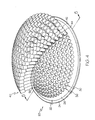
- Convex portion (22) has an outer surface (26) and an inner surface (28), and a plurality of openings (30) formed therethrough.
- convex portion (22) has 271 openings (30), each being configured to receive a camera (40).
- any suitable number of openings (30) may be used, including but not limited to less than 100, more than 100, more than 200, more than 300, or any other suitable number.
- Each opening (30) of the present example has a diameter of approximately 38 mm, though any other diameter may be used.
- convex portion (22) may have an inside radius of curvature between approximately 24", inclusive, and approximately 26", inclusive; and an outside radius of curvature between approximately 24.125", inclusive, and approximately 26.125", inclusive.
- Convex portion (22) of the present example has an inside radius of curvature of approximately 24", and an outside radius of curvature of approximately 24.125". Alternatively, any other inside or outside radius of curvature may be used. In another embodiment, convex portion (22) has a hyperbolic or parabolic curvature. Other suitable configurations will be apparent to those of ordinary skill in the art.
- camera mount (20) is generally flat.
- each camera (40) may be aimed at a common phantom point or may be otherwise oriented.
- the lines of sight of cameras (40) may nevertheless intersect in a manner similar to that described herein with respect to the curved camera mount (20), and such lines of sight may have relative angular relationships similar to those described herein with respect to the curved camera mount.
- cameras (40) are provided in a variety of sizes. For instance, a relatively large camera (40) may be provided in the center of an array of relatively smaller cameras (40). Similarly, several cameras (40) may be provided with different optical properties or other differing properties. It will therefore be appreciated that all cameras (40) mounted to camera mount (20) need not be uniformly the same.
- Each camera (40) of the present example comprises a sensor portion (42) and a lens portion (44), which will be described in greater detail below.
- Cameras (40) are positioned on convex portion (22) of camera mount (20) such that each lens portion (44) is oriented radially inward. It will therefore be appreciated that, where a plurality of cameras (40) are secured to camera mount (20), lens portions (44) of cameras (40) will have intersecting lines of sight.
- Each lens portion (44) of the present example is secured to convex portion (22) by a respective collar (50), an example of which is shown in FIGS. 6 and 7 . As shown, each collar (50) has a sidewall (52), an inner recessed portion (54), and an outer recessed portion (56).
- Each sidewall (52) has a plurality of threaded openings (64) formed therethrough.
- Inner recessed portion (54) has an inner shoulder (58) extending radially inward; while outer recessed portion (56) has an outer shoulder (60) extending radially outward.
- collar (50) comprises an angled portion (62) that defines a frusto-conical aperture. Angled portion (62) is adjacent to inner shoulder (58), and defines an angle of approximately 60° relative to inner shoulder (58). Of course, any other suitable orientation or configuration may be used.
- a pan-tilt-zoom (PTZ) camera (not shown) is used in combination with cameras (40).
- a PTZ camera may be mounted to the same platform as cameras (40).
- a PTZ camera may be located elsewhere.
- a camera system such as one described in U.S. Pub. No. 2006/0028550 , entitled “Surveillance System and Method," the disclosure of which is incorporated by reference herein, is used in combination with cameras.
- a camera system may be generally co-located with cameras (40) and/or may be located elsewhere.
- Other cameras or camera systems that may be suitable for combining with cameras (40) will be apparent to those of ordinary skill in the art.
- collars (50) are secured to camera mount (20) by inserting outer recessed portion (56) of each collar (50) into a respective opening (30), such that outer shoulder (60) is adjacent to outer surface (26) of convex portion (22). It will be appreciated that this may be repeated until every opening (30) has a corresponding collar (50) inserted therein.
- collars (50) are secured to convex portion (22) using an adhesive or epoxy.
- outer recessed portions (56) and openings (30) are threaded, such that collars (50) may be screwed into openings (30).
- collars (50) may be secured to camera mount (20)
- camera mount (20) may be constructed such that collars (50), or structures similar thereto, are integrally formed with camera mount (20).
- collars (50) such as those described herein are merely optional.
- lens portions (44) are inserted into collars (50) and secured thereto.
- a lens portion (44) is inserted into each collar (50) such that the distal or objective end of lens portion (44) is adjacent inner shoulder (58).
- Each lens portion (44) is then secured to its corresponding collar (50) by inserting and tightening a set screw (not shown) into threaded openings (64) formed through sidewall (52) of collar (50).
- a set screw not shown
- lens portion (44) may be any commercial off-the-shelf (COTS) lens assembly, and that each camera (40) may be a COTS camera.
- COTS commercial off-the-shelf
- the use of set screws or other devices may permit collar (50) to accommodate and secure various types of lens portions (44) having various outer diameters.
- lens portion (44) may be screwed into collar (50). Still other suitable structures and techniques for securing lens portion (44) to collar (50) will be apparent to those of ordinary skill in the art.
- lens portion (44) may be configured such that a structure similar to collar (50) is integrally formed therewith. It will therefore be appreciated that collar (50), as a piece separate from lens portion (44), is merely optional, as are other components described herein.
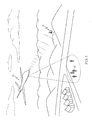
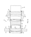
- FIG. 8 shows camera mount (20) secured to the fuselage (80) of aircraft (10) by a fixture (70).
- fixture (70) comprises a "Pictorvision XR" structure by Pictorvision Inc. (formerly Wescam), of Van Nuys, California.
- Pictorvision Inc. formerly Wescam
- any other type of fixture (70) may be used.
- fixture (70) may have any of a variety of properties.
- fixture (70) may be substantially rigid, such that fixture (70) prohibits movement of camera mount (20) relative to fuselage (80).
- fixture (70) may comprise gimbal features or similar features, permitting some degree of movement of camera mount (20) relative to fuselage (80).
- fixture (70) may comprise pads, cushions, resilient members, etc., configured to provide dampening, or other features configured to prevent transfer of vibrations from fuselage (80) to camera mount (20). Still other suitable features and configurations for fixture (70) will be apparent to those of ordinary skill in the art.
- window (82) is provided in fuselage (80), permitting cameras (40) to "see” through fuselage (80).
- each camera (40) is oriented such that all cameras (40) point through a common central aperture provided by window (82). More particularly, cameras (40) of the present example have intersecting lines of sight. As shown in FIG. 8 , the intersecting lines of sight of the outermost cameras (40) form a maximum convergence angle (84). The vertex of this angle (84) may be regarded as a "phantom point.” While the lines of sight of the outermost cameras (40) are shown as converging generally at window (82), it will be appreciated that these lines of sight may converge elsewhere (e.g., above window (82), below window (82), etc.).
- the lines of sight diverge through what may be regarded as a region of divergence.
- subjects e.g., persons, places, objects, events, etc.
- the lines of sight may converge approximately at the subject.
- the subject may be positioned such that the subject is located between cameras (40) and the "phantom point.”
- window (82) is substantially flat on both sides, though it will be appreciated that either or both sides of window (82) may be curved, such that window (82) may be provided as a lens element.
- window (82) of the present example has a diameter of approximately 202.9 mm, it will be appreciated that any other suitable diameter or dimension(s) may be used.
- maximum convergence angle (84) is approximately 92°. In another embodiment, the maximum convergence angle (84) is approximately 81°. Of course, any other suitable maximum convergence angle (84) may be used.
- camera mount (20) may be configured or used such that the lines of sight of the outermost cameras (40) do not converge. It will also be appreciated that maximum convergence angle (84) may vary as a function of the radius of curvature of convex portion (22) of camera mount (20), and/or a variety of other factors.
- the field of view obtained by cameras (40), collectively may be proportional to the maximum convergence angle (84) or have some other relationship with the maximum convergence angle (84). Alternatively, the field of view collectively obtained by cameras (40) may be disproportional to the maximum convergence angle (84).
- a dampening structure or feature may be incorporated into or between cameras (40), camera mount (20), fixture (70), and/or elsewhere.
- a dampening structure or feature may comprise any number of the following: springs, rubber or foam pads, pneumatics, gimbals, etc.
- different components of an image capture system may be dampened in different ways, if at all. Other dampening techniques, as well as alternatives to dampening, will be apparent to those of ordinary skill in the art.
- images captured by cameras (40) may be combined to form a collective, wide angle image, such that an image captured by a single camera (40) may be regarded as a "tile" of the larger image.
- mosaicking techniques may be used to eliminate motion between such tiles (e.g., motion or translation of one tile relative to another tile); while global motion estimation may be used to address motion of the collective, wide angle image. In other words, mosaicking may be used to address motion of cameras (40) relative to each other, while global motion estimation may be used to address collective motion of cameras (40) relative to the ground.
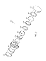
- lens portion (44), described above comprises lens assembly (90).
- lens assembly (90) comprises a housing (92) or barrel, a plurality of lens elements (94, 96, 98), caps (100, 102), spacers (104, 106), and retainers (108, 110).
- a circumferential flange (120) extends radially outward near the objective end of lens assembly (90).
- lens assembly (90) is configured such that front lens element (94) is positioned distally (e.g., at the objective end of lens assembly (90)), rear lens element (98) is positioned proximally, and middle lens element (96) is positioned between front lens element (94) and rear lens element (98).
- lens portion (44) may comprise one or more features providing the option of taking lens portion (44) apart for any purpose.
- housing (92) of lens assembly (90) may be configured in separate parts having complimentary threaded features, such that housing (92) may be taken apart by unscrewing these parts from each other. Other ways in which housing (92) may be varied will be apparent to those of ordinary skill in the art.
- lens assembly (90) is configured such that light (112) passes through front lens element (94) first, then through middle lens element (96), then through rear lens element (98). This provides an image projection (114) to an image plane (116).
- sensor portion (42) is located within image plane (116), such that image projection (114) is received by sensor portion (42).
- lens elements (94, 96, 98) may have any other suitable configurations, and that any number or types of lens elements may be used.
- Front lens element (94) comprises a convex first surface (120) and a substantially flat second surface (122).
- Convex first surface (120) has a radius of curvature of approximately 48.785 mm, though any other suitable radius of curvature may be used.
- second surface (122) need not necessarily be substantially flat, and may have any suitable radius of curvature.
- second surface (122) may be slightly concave.
- front lens element (94) comprises a SCHOTT SK16 glass. Alternatively, any other suitable glass may be used.
- Middle lens element (96) is bi-concave, and comprises a concave first surface (124) and a concave second surface (126).
- Concave first surface (124) has a radius of curvature of approximately 135.35 mm; while concave second surface (126) has a radius of curvature of approximately 41.107 mm.
- middle lens element (96) comprises a SCHOTT F4 glass. Alternatively, any other suitable glass may be used.
- Rear lens element (98) comprises a convex first surface (128) and a convex second surface (130).
- Convex first surface (128) has a radius of curvature of approximately 115.24 mm; while convex second surface (128) has a radius of curvature of approximately 193.241 mm.
- any other suitable radius of curvature may be used for either or both of convex first surface (128) or convex second surface (130).
- rear lens element (98) comprises a SCHOTT SK16 glass. Alternatively, any other suitable glass may be used.
- FIG. 12 depicts a series of alternative lens elements (140, 142, 144, 146, 148, 150).
- first lens element (140) comprises a convex first surface (152) and a concave second surface (154).
- Second lens element (142) comprises a convex first surface (156) and a substantially flat second surface (158).
- Third lens element (144) comprises a convex first surface (160) and a substantially flat second surface (162).
- Fourth lens element (146) comprises a substantially flat first surface (164) and a concave second surface (166).
- third and fourth lens elements (144, 146) are positioned such that substantially flat first surface (164) of fourth lens element (146) is adjacent substantially flat second surface (162) of third lens element (144).
- Fifth lens element (148) comprises a substantially flat first surface (168) and a convex second surface (170).
- Sixth lens element (150) comprises a convex first surface (172) and a concave second surface (174).
- fifth and sixth lens elements (148, 150) are positioned such that convex first surface (168) of sixth lens element (150) is adjacent convex second surface (170) of fifth lens element (148).
- these configurations for lens elements (140, 142, 144, 146, 148, 150) are merely exemplary, and any number of lens elements or lens element configurations may be used.
- FIG. 13 shows an example of how lens assembly (90) may be secured to camera mount (20).
- a portion of the objective end of lens assembly (90) is inserted through camera mount (20), such that the circumferential flange (120) of lens assembly (90) is adjacent outer surface (26) of camera mount (20).
- a securing ring (118) is engaged with the objective end of lens assembly (90), and is adjacent inner surface (28) of camera mount (20). Securing ring (118) and circumferential flange (120) thus “sandwich” camera mount (20), thereby securing lens assembly (90) to camera mount (20) in a clamping fashion.
- Other suitable methods for securing a lens assembly (90) or camera (40) to camera mount (20) will be apparent to those of ordinary skill in the art.
- Each camera (40) of the present example has the following parameters, each being merely approximate in value: an F-number of 6; an effective focal length of 180 mm; an image distance of 124 mm; an image size of 2048x2048 pixels (or 24x24 mm); a spectral range of 450-700 nm; a length of 200 mm; a field of view of 10.8°; an entrance pupil diameter of 30 mm; a depth of field ranging from 1.5 km to infinity; and a pixel pitch of 12 microns.
- each of these listed parameter values is merely exemplary, and any other suitable parameter values may be used.
- cameras (40) may have a spectral range falling anywhere between approximately 300 and approximately 30,000 nm, inclusive.
- an image formed by combining images captured substantially simultaneously with cameras (40) comprises approximately one billion pixels, such that cameras (40) collectively form a single "gigapixel camera.”
- each sensor portion (42) comprises a sensor element (not shown) that is operable to capture visible light (e.g., having a wavelength between approximately 450 nanometers and approximately 700 nanometers).
- Each sensor portion (42) may comprise a CCD sensor (e.g., frame transfer, interline transfer, etc.), a CMOS sensor (e.g., with an electronic rolling shutter), or any other type of sensor.
- sensor portion (42) may comprise a LUPA 4000 sensor by Cypress Semiconductor Corporation of San Jose, California, though any other sensor may be used.
- cameras (40) are configured to obtain monochrome images. In another embodiment, cameras (40) are configured to obtain polychrome images.
- sensor portions (42) comprise infrared imaging components, such that cameras (40) comprise infrared cameras.
- Infrared cameras (40) may comprise passive night vision components, active night vision components, or combinations thereof.
- a cameras (40) is operable to capture both infrared and non-infrared images.
- Sensor portions (42) of the present example are configured to provide a global shutter.
- cameras (40) are configured to all capture images substantially simultaneously and synchronously.
- a global shutter may be provided mechanically and/or electronically.
- a mechanical or electronic global shutter may cause the exposure time for each camera (40) to begin and end at substantially the same time as the other cameras (40).
- Suitable techniques for implementing a global shutter will be apparent to those of ordinary skill in the art.
- a global shutter is not necessary, and that any suitable alternative may be used.
- an algorithm may be used to register pixels to a common time. Suitable methods of implementing such an algorithm will be apparent to those of ordinary skill in the art, as will other alternatives to a global shutter.
- Sensor portions (42) may be secured to corresponding lens portions (44) in any suitable way.
- sensor portions (42) and lens portions (44) may comprise complimentary threaded features, such that a sensor portion (42) may be screwed on to a corresponding lens portion (44).
- sensor portion (42) may be configured to clasp or latch onto a corresponding lens portion (44).
- a sensor portion (42) may be permanently coupled with a corresponding lens portion (44), such as by welding, using adhesives, integral formation, or using other techniques.
- Other suitable structural relationships between lens portion (44) and sensor portion (42) will be apparent to those of ordinary skill in the art.
- sensor portions (42) may be clocked by rotating each sensor portion (42) until the bottom of each sensor portion (42) is the same distance from outer surface (26) of camera mount (20) as the bottom of other sensor portions (42).
- Sensor portions (42) may also be clocked by aligning the respective bottom edges of all sensor portions (42) such that they are all parallel.
- Such clocking methods may be done in the embodiment where housing (92) of lens assembly (90) comprises two portions screwably secured together, such that each sensor portion (42) may be rotated, or in any other suitable embodiment.
- sensor portions (42) are activated, and video captured by sensor portions (42) is viewed.
- clocking may be performed by rotating sensor portions (42) until objects or features within captured images are consistently aligned among views from adjacent sensor portions (42). It will be appreciated that clocking may initialize the search space for a mosaicking algorithm. Other methods for clocking or aligning sensor portions (42) will be apparent to those of ordinary skill in the art.
- cameras (40) when cameras (40) are located approximately 7.6 km, or approximately 25,000 ft, above the ground (e.g., cameras (40) mounted in an aircraft (10)), cameras (40) may collectively view and capture an image of an area (a "footprint") that is approximately 11 km by approximately 11 km. Cameras (40) may be configured such that such an image has a resolution of approximately 0.5 meters. By way of example only, cameras (40) may provide approximately 50% contrast of features larger than 0.5 meters in size within an approximately 11x11 km ground footprint from an altitude of approximately 7.6 km. It will be appreciated that the size of the ground footprint associated with cameras (40) may vary as a function of cameras' (40) altitude, as may resolution.
- cameras (40) may provide a resolution of 0.5 m from an altitude of 7.6 km
- cameras (40) may provide a resolution of 1.2 m from an altitude of 18 km.
- Other suitable degrees of resolution, altitudes, and footprint sizes may be used.
- Cameras (40) of an exemplary image capture system incorporate sensors that are all of the same effective focal length and entrance pupil size thus sampling a scene at a constant angular rate.
- a sensor with a lens well corrected for geometrical distortion each pixel linearly maps a plane onto the respective sensor array.
- the composite scene observed by an image capture system may be uniformly scaled for planes at a constant distance from the respective sensor.
- the change in scale may be proportional to the change in distance to the scene.
- each sensor entrance pupil may be co-located at a common point, and the respective pupil plane is simply rotated about that point to sample the entire image capture system field-of-view.
- This quantity may provide a means for adjacent sensors to sample more or less of a common volume of the image capture system field-of-view.
- Each sensor may sample the image capture system field-of-view and each pixel of the respective sensor array may sample the respective sensor sample. It may also be possible to have each sensor designed to scale the volume of the image capture system field-of-view such that a plane perpendicular to the image capture system boresight direction is sampled by the inverse of the angle.
- a suitable frame rate may be greater than or equal to approximately 5 frames per second.
- any other suitable frame rate may be used, including less than 5 frames per second.
- Each camera (40) may also capture images with an exposure time of approximately 1 ms, with an aperture of approximately f2.8, using an ND4 neutral density filter. Other suitable exposure times, aperture settings, and filter selections will be apparent to those of ordinary skill in the art.
- calibration may be used to detect and/or correct mounting inaccuracies or inconsistencies of sensor portions (42) or lens portions (44).
- calibration may be provided to facilitate adjustment of cameras (40) such that their respective lines of sight all intersect at a single common point to the greatest extent possible.
- Calibration may also be provided to provide a consistent distance from each sensor portion (42) to its respective first lens (94).
- calibration may be used to obtain some corrective factor or factors to be accounted for during image processing. In other words, structural or other imperfections discovered during calibration may be accounted for during image processing, to address adverse effects that would otherwise be caused by such imperfections.
- lens portions (44) are used to project light onto a planar checkerboard pattern (not shown) positioned beneath camera mount (20).
- Checkerboard pattern comprises a plurality of squares, each square being associated with a respective lens portion (44).
- Each lens portion (44) is adjusted relative to camera mount (20) until light shone through lens portion (44) is centered in its corresponding square in the checkerboard pattern.
- a collimator (not shown) is positioned under the center of camera mount (20).
- the collimator is configured to rotate about two axes.
- Light is provided to and by the collimator, and collimator is rotated about the two axes to selectively direct the light into each camera (40).
- each lens portion (44) is adjusted relative to camera mount (20) to ensure that light provided by the collimator reaches sensor portion (42) secured to such lens portion (44) when collimator is directed toward corresponding camera (40).
- Calibration may also be used to account for hardware errors or aberrations (e.g., defects in a lens element (94, 96, 98), defects in a sensor, etc.), certain environmental factors, or other factors that it may be desirable to take into account during image processing.
- any of the following may be determined during calibration: geometrical distortion and/or non-uniform illumination over the field of view, non-uniform response of each pixel in an array, dead pixels in an array, non-uniform gain and/or offset for each pixel in an array, etc.
- errors or factors may be characterized during calibration and corrected or otherwise addressed during image processing.
- images captured by cameras (40) may be combined to form a wide angle image, such as a wide angle video image.
- images captured by cameras (40) could alternatively be combined to form an image having any suitable field of view, such as a narrow field of view.
- images captured by cameras (40) may be processed and presented to a user in an interactive fashion. For instance, referring back to FIG. 1 , images captured from within aircraft (10) may be transmitted to a user at a ground station (14) or elsewhere. Where at least a portion of a wide angle image captured collectively by cameras (40) is presented to a user, the user may be permitted to select a portion if this image to view in greater detail.
- the user may thus be provided with a "virtual pan-tilt-zoom (PTZ) camera," which may effect panning, tilting, and/or zooming within a relatively large, wide angle image for presentation of a selected portion of (or selected view within) that wide angle image to the user via a user interface.
- a "virtual pan-tilt-zoom (PTZ) camera” which may effect panning, tilting, and/or zooming within a relatively large, wide angle image for presentation of a selected portion of (or selected view within) that wide angle image to the user via a user interface.
- PTZ virtual pan-tilt-zoom
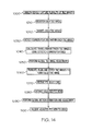
- FIG. 14 illustrates several acts that may be performed as part of a method for processing images captured by cameras (40).
- a plurality of images are captured by cameras (40) substantially simultaneously. For purposes of this example only, each of such images will be referred to as a "tile image.”
- each tile image is then registered. Such registration may comprise associating each image with the particular camera (40) the image was captured with, the time the image was captured, a geographic location within the field of view provided by the image, and/or any other information.
- each tile image is sharpened. Such sharpening may comprise brightness correction, contrast enhancement, fixed pattern noise removal, gamma correction, dead pixel detection and interpolation, white clip, de-warping, vignetting correction, and/or any other suitable processes.
- the sharpened tile images may be subject to corner detection. While the term "comer detection” is used to designate this act, it is not intended to necessarily limit the act to the detection of corners (e.g., corners of a tile image or corners within a tile image) only. Indeed, any suitable features within a tile image may be detected as part of this act. For instance, detected tile image features may comprise image locations having gradients in all directions at a predetermined scale. It will be appreciated that the corner detection may provide a plurality of reference points within an image, and that such reference points may be useful later in processing.
- motion e.g., translation, affine, projective, etc.
- mosaicking techniques may be used to eliminate motion between such tile images (e.g., motion or translation of one tile image relative to another tile image).
- this act comprises comparing the relative locations of detected comers/features within adjacent tile images that have been captured at the same time.
- global motion estimation and adjustment may be performed. In contrast to the mosaicking associated with block (1040), which is focused on adjacent tile image pairs, global motion estimation is focused more on the collection of tile images.
- global motion estimation may include a comprehensive comparison of a plurality of motion or translation findings and/or corrections that were made in block (1040). Such global motion estimation may thus be used to detect and correct any errors that occurred during the motion detection and correction that occurred in block (1040).
- blocks (1040, 1050) may reveal that the tile images captured in block (1000) were appreciably misaligned relative to each other when they were initially captured. It will therefore be apparent to those of ordinary skill in the art that some degree of spatial overlap among the views associated with adjacent tile images may facilitate the process performed in accordance with block (1040), by permitting common comers/features to be detected in more than one tile image during performance of the act corresponding to block (1030). Such overlap may also reduce the likelihood of gaps in image data occurring. Accordingly, in the present example, images obtained by cameras (40) have some degree of overlap. For instance, an image obtained by a given camera (40) may have approximately 42% or 43% overlap with images obtained by cameras (40) adjacent to that particular camera (40). Alternatively, any other suitable degree of overlap may be used.
- a collective image created in accordance with block (1060) need not necessarily include all tile images stitched together.
- a collective image may comprise portions of several tile images, a single tile image, or even a portion of a single tile image.
- stitching in accordance with block (1060) may be performed in substantially real time (e.g., stitching as images are being captured by cameras (40)).
- stitching may be performed at a later time, such as after tile images have been stored for some time.
- tile images may be orthorectified (e.g., such that the center of cameras (40) appears to be at infinity) prior to, during, or after stitching.
- stitching may be performed by correlating features within each tile image with features on a map or model. Such correlation may be used in lieu of (or in addition to) corner detection discussed above with reference to block (1030).
- Other suitable stitching techniques will be apparent to those of ordinary skill in the art.
- a user may be provided with a "virtual pan-tilt-zoom (PTZ) camera," which may effect panning, tilting, and/or zooming within the image created in block (1060).
- the user may thus be permitted to selectively view selected portions of (or selected views within) the wide angle image via a user interface.
- PTZ selections may be received.
- PTZ selections may be indicative of the image region, view perspective, and/or zoom level desired by the user.
- the region of the collective image corresponding to the selected PTZ view may be extracted, as shown in block (1080).
- a PTZ view extracted in accordance with block (1080) may tend to "move" with the platform.
- additional processing may be used to provide the appearance of a static or fixed perspective.
- a global motion estimation and adjustment may be performed. Such a process may account for movement of the platform by essentially cancelling such movement from the extracted PTZ view.
- a global motion estimation method comprises a random sample consensus algorithm (RANSAC).
- RANSAC may be used to provide homography mapping between consecutive frames or images captured by cameras (40). In the present example, this is performed at a global level (e.g., using images captured simultaneously by a plurality of cameras (40)), though it may also be performed at the tile level (e.g., using images captured by a single camera (40)).
- Global motion estimation may also be based, at least in part, on physical parameters, such as the speed and altitude of aircraft (10), by way of example only. Other suitable methods for performing global motion estimation will be apparent to those of ordinary skill in the art.
- the camera (40) source(s) for extracted PTZ images may be changed as the platform moves, thereby providing an appearance of a fixed perspective in the extracted PTZ image.
- an adjusted PTZ view may be provided to the user in accordance with their selections.
- images captured by cameras (40) may be registered with geographical ground coordinates corresponding to a geographical area within the field of view of cameras (40).
- Geo-registration may provide correlation between a view of a particular camera (40), or a portion of such a view, and a corresponding location on a map.
- Geo-registration information may be obtained using any suitable techniques. For instance, information relating to the geographical position of aircraft (10) may be obtained using GPS technology or other technology, and may be correlated with images captured by cameras (40), as a function of time, in order to obtain at least a rough idea of the geographical location being viewed by cameras (40) at such time.
- Resolution or accuracy of geo-registration information may be refined by accounting for additional factors, such as the line-of-sight orientation of the camera(s) (40) associated with selected image portions, together with altitude information, by way of example only.
- Another technique for obtaining geo-registration information may comprise recognizing and correlating objects detected within the field of view of cameras (40) (e.g., using object recognition logic) with objects having a known geographic locations, such as prominent landmarks, etc. Other methods of obtaining geo-registration information will be apparent to those of ordinary skill in the art.
- Geo-registration information may be transmitted with images captured by cameras (40), or may otherwise be obtainable based on data relating to images captured by cameras (40). For instance, geo-registration may be performed within aircraft (10), at ground station (14), and/or elsewhere. To the extent that geo-registration information may be transmitted with images, such geo-registration information may be provided as annotations to images or may be otherwise provided.
- persons or objects of interest may be tracked (e.g., automatically). For instance, such tracking may comprise automatically adjusting the view presented (1100) to the user such that the person/object of interest remains substantially centered within the presented view as the person/object moves.
- a movable platform e.g., an aircraft (10)
- automated tracking may further carry over into movement of the platform (e.g., by automatic control, by providing tracking navigation information to a pilot, etc.), to the extent that the person/object of interest would otherwise leave the collective field of view of cameras (40) mounted to the platform. Tracking may occur at a tile image level and/or at a globally fused image level. Other methods for effecting tracking will be apparent to those of ordinary skill in the art.
- the image processing may include object recognition, facial feature recognition, etc., such that tracking is initiated upon recognition of a particular object, person, event, etc.
- object/facial/event recognition may be used to detect a particular object/person/event within the collective field of view of cameras (40), and may automatically provide a zoomed-in view of the recognized object/person/event.
- Tracking may also be initiated in accordance with a user selection provided through a user interface. For instance, a user may "click on" an object of interest, or provide some other form of input to designate an object of interest, and the designated object may be tracked accordingly.
- Initiation of tracking may also be a combination of automatic and manual.
- a recognition algorithm may recognize a person or object of interest, and present a user, via a user interface, with the option to decide whether the person or object should be tracked.
- the user may zoom in on the person or object for further inspection in order to determine whether tracking is warranted. If tracking is desired, the user may indicate the same through a user interface, and the person or object may be tracked accordingly. It will be appreciated that still other methods for initiating tracking may be used, to the extent that tracking is available.
- a collective image created in block (1060) may consist solely of corrected and stitched tile images corresponding to a user's PTZ selections received per block (1070). It will therefore be appreciated that image processing may be streamlined based on a user's PTZ selections, such that only portions of image data corresponding to the user's indicated area of interest are processed. Alternatively, the tiled images outside the user's indicated area of interest may still be processed, such as for storage or other purposes.
- processing may be executed on hardware at various locations.
- the processing may occur on hardware that is substantially co-located on the platform with cameras (40) (e.g., located within aircraft (10)), such that the adjusted PTZ view is transmitted to the user from the platform.
- registered tile images may be transmitted from the camera (40) platform to a remote location, where hardware performs the acts corresponding to blocks (1020, 1030, 1040, 1050, 1060, 1070, 1080, 1090, 1100).
- blocks (1020, 1030, 1040, 1050, 1060, 1070, 1080, 1090, 1100) Still other ways in which image processing acts may be allocated among hardware at various locations will be apparent to those of ordinary skill in the art.
- a user interface permits users to view at least a portion of one or more images captured by one or more cameras (40), and further permits users to provide PTZ selections, such as those described above, as input.
- a user interface may also incorporate a feature such as an interactive map.
- an interactive map may provide a substantially real time visual indication of the geographical area within the collective field of view of cameras (40).
- An interactive map may also permit the user to select geographical areas of interest, and a PTZ view of such areas may be provided in response to such selections.
- An interactive map may therefore provide an instrument for making PTZ selections as described above.
- An interactive map may thus provide a remote control of aircraft (10) (or other vehicle), in addition to providing an instrument for making PTZ selections.
- An interactive map may have any other suitable features.
- a user interface may comprise or share similarities with any of the user interfaces described in U.S. Application Publication No. 2006/0033813 , entitled “Immersive Surveillance System Interface,” the disclosure of which is incorporated by reference herein.
- a collective image described herein may be presented in a manner similar to the equirectangular image described in that publication; with PTZ selections and views described herein being made and presented in a manner similar to the PTZ selections and views described in that publication, respectively.
- the user interface described in that publication may be modified to suit the present examples, and variations thereof, in any other suitable ways. Still other ways in which a user interface may be provided will be apparent to those of ordinary skill in the art.
- image capture systems described herein may be combined with image capture systems such as those described in U.S. Application Publication No. 2006/0033813, and that views provided by such combined image capture systems may be correlated in a variety of ways, including but not limited to using correlation methods described in that publication.
- camera mount (20) with cameras (40) may be positioned within an aerostat (or other airborne platform), with cameras (40) persistently capturing images of an urban area while the aerostat is floating over the urban area. Images captured by cameras (40) may be stored in a storage device located within the aerostat and/or may be transmitted to a remote location (e.g., ground station (14)), for storage and/or review. If a car bomb or other device explodes, images captured by cameras (40) may be reviewed for details of the explosion. For instance, a user interface may permit a user to zoom in on the region of the image where the explosion occurred, then backtrack through the video to determine the source of the bomb.
- a remote location e.g., ground station (14)
- the user interface may permit the user to "rewind" video captured by cameras (40) to determine the type of car used, the route driven by the car prior to its explosion, the car's origin, the identity of the driver, etc.
- the cameras (40) and user interface may also be used to evaluate activity following the explosion. For instance, video captured by cameras (40) may be monitored to look for and track terrorists fleeing the scene of the explosion.
- an image capture system further includes other cameras (e.g., PTZ cameras, etc.) fixedly located throughout the urban area, views obtained using cameras (40) may be correlated with views obtained by such fixed cameras to provide additional perspectives of people, places, events (e.g., explosions), or things of interest.
- Other ways in which cameras (40) may be used to provide information relating to a bombing incident or similar incident will be apparent to those of ordinary skill in the art.
- cameras (40) on camera mount (20) comprises the provision of a tactical "eye in the sky" view for military reconnaissance or similar purposes.
- camera mount (20) with cameras (40) may be positioned within an aircraft (10), with cameras (40) capturing images while aircraft (10) is flying over enemy territory or unknown territory. Images captured by cameras (40) may be transmitted to military command personnel located at ground station (14) in substantially real time. It will be appreciated that several users (e.g., at different locations) may simultaneously view the same or different portions of a collective image captured by cameras (40).
- Aircraft (10) and cameras (40) may permit commanders to interactively view activity or objects over a hill, for instance, or at other remote locations of interest, without the need to use human scouts, and in substantially real time.
- a user interface may initially provide a wide angle image to the user, then permit the user to select areas of interest for a closer, high resolution view. Information related to the geographical location of the area of interest may also be transmitted to the user via the user interface.
- the user interface may further permit such users to remotely control aircraft (10), in addition to permitting such users to effect a "virtual pan-tilt-zoom camera" within a wide angle video image.
- aircraft (10) may automatically track moving people (12) or objects of interest to provide a persistent high resolution view of such people (12) or objects and/or to provide targeting information relating to the same.
- Other suitable reconnaissance uses or similar uses will be apparent to those of ordinary skill in the art.
- a camera mount (20) with cameras (40) may be positioned within an aircraft (10), which may persistently fly or hover over borders. Images captured by cameras (40) may be processed to automatically detect border crossers (e.g., using motion detection and/or object recognition logic). Where border crossers are automatically or otherwise detected, a portion of the wide angle image occupied by the border crossers may be zoomed in, and the border crossers may be automatically tracked. Such automated tracking may further carry over into control of aircraft (10) flight, to the extent that the border crossers would otherwise leave the collective field of view of cameras (40) within aircraft (10).
- border crossers e.g., using motion detection and/or object recognition logic
- Images of border crossers may be transmitted to ground station (14), along with information related to the geographic location of the border crossers, with an alert of the border crossers' presence.
- an image capture system further includes other cameras (e.g., PTZ cameras, etc.) fixedly located throughout the urban area
- views obtained using cameras (40) may be correlated with views obtained by such fixed cameras to provide additional perspectives of people, places, or things of interest.
- a combination of camera mount (20) and cameras (40) may be used in a border patrol setting in any other suitable way. Similar implementations may include visual security (e.g., surveillance of a premises).
Abstract
Description
- This application claims priority to
U.S. Provisional Patent Application Serial No. 60/772,670 - This invention was made with Government support under DARPA Contract No. NBCHC050090 awarded by the U.S. Department of the Interior - National Business Center on behalf of a Department of Defense Agency - Defense Advanced Research Projects Agency. The Government has certain rights in the invention.
- Image capture systems have existed in a variety of forms since the inception of photography. One type of image capture system includes an array of cameras used to capture several images that are stitched together to form a single unitary image or a composite image. While a variety of methods and apparatuses for capturing images have been made and used, it is believed that no one prior to the inventors has made or used the invention described in the appended claims.
- While the specification concludes with claims which particularly point out and distinctly claim the invention, it is believed the present invention will be better understood from the following description of certain examples taken in conjunction with the accompanying drawings, in which like reference numerals identify the same elements and in which:
-
FIG. 1 depicts an exemplary image capture and transmission system; -
FIG. 2 depicts a perspective view of an exemplary mount for an array of cameras; -
FIG. 3 depicts a cross-sectional view of the mount ofFIG. 2 , taken along line 3-3; -
FIG. 4 depicts a perspective view of the mount ofFIG. 2 with a plurality of cameras mounted thereto; -
FIG. 5 depicts a cross-sectional view of the mount ofFIG. 4 , taken along line 5-5; -
FIG. 6 depicts a perspective view of an exemplary collar suitable for securing a camera to the mount ofFIG. 2 ; -
FIG. 7 depicts a cross-sectional view of the collar ofFIG. 6 ; -
FIG. 8 depicts a cross-sectional view of the mount ofFIG. 2 secured to a fuselage; -
FIG. 9 depicts an exploded view of an exemplary lens assembly; -
FIG. 10 depicts a cross-sectional view of the lens assembly ofFIG. 9 ; -
FIG. 11 depicts light passing through lens elements of the lens assembly ofFIG. 9 ; -
FIG. 12 depicts light passing though exemplary alternative lens elements suitable for use in the lens assembly ofFIG. 9 ; -
FIG. 13 depicts a partial cross-sectional view of the lens assembly ofFIG. 9 mounted to the mount ofFIG. 2 ; and -
FIG. 14 depicts a flow chart showing acts in an exemplary image processing method. - The following description of certain examples of the invention should not be used to limit the scope of the present invention. Other examples, features, aspects, embodiments, and advantages of the invention will become apparent to those skilled in the art from the following description, which is by way of illustration, one of the best modes contemplated for carrying out the invention. As will be realized, the invention is capable of other different and obvious aspects, all without departing from the invention. Accordingly, the drawings and descriptions should be regarded as illustrative in nature and not restrictive.
- As shown in
FIG. 1 , and as will be described in greater detail below, the image capture system of the present example employs the use of an aircraft (10) for the capture of overhead, wide-angle video images of people (12), facilities, cities, or other places or things within the field of view of the image capture system. At least a portion of the captured images are transmitted in approximately real time to a ground station (14). While not depicted, a plurality of ground stations (14) may be provided, with at least one ground station (14) acting as a relay between other ground stations (14) and aircraft (10). - While aircraft (10) depicted in
FIG. 1 is an unmanned drone, it will be appreciated that any other type of aircraft (10) may be used, including but not limited to a manned airplane, a helicopter, an airship, a balloon, or another type of aerostat. It will also be appreciated that an image capture system may be used in any other type of vehicle, including but not limited to land vehicles, watercraft, etc. Alternatively, an image capture system may be secured to a structure in a fixed location, such as a tower, building, etc. An image capture system may also include a combination of image capturing portions in an aircraft or other vehicle and image capturing portions secured to a fixed location. While several examples herein contemplate an image capture system being oriented vertically, such that its view is directed generally downward, it will be appreciated that image capture systems described herein may also be oriented horizontally or provided in any other suitable orientation. Other ways in which an image capture system may be provided and used will be apparent to those of ordinary skill in the art. - As shown in
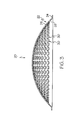
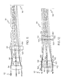
FIGS. 2-5 , the image capture system of the present example comprises a camera mount (20) or optical bench. Camera mount (20) may comprise acrylic, polycarbonate, or any other plastic, aluminum or any other metal, or any other material(s), including combinations thereof. As shown, camera mount (20) has a dome-like convex portion (22), and a lip (24), which defines a circumference of camera mount (20) and extends radially outward. Alternatively, lip (24) may have any suitable angle or other configuration. By way of example only, lip (24) may have an inner diameter between approximately 46", inclusive, and approximately 48", inclusive; and an outer diameter between approximately 48", inclusive, and approximately 50", inclusive. Alternatively, any other inner or outer diameter may be used. - Convex portion (22) has an outer surface (26) and an inner surface (28), and a plurality of openings (30) formed therethrough. In the present example, convex portion (22) has 271 openings (30), each being configured to receive a camera (40). It will be appreciated, however, that any suitable number of openings (30) may be used, including but not limited to less than 100, more than 100, more than 200, more than 300, or any other suitable number. Each opening (30) of the present example has a diameter of approximately 38 mm, though any other diameter may be used. By way of example only, convex portion (22) may have an inside radius of curvature between approximately 24", inclusive, and approximately 26", inclusive; and an outside radius of curvature between approximately 24.125", inclusive, and approximately 26.125", inclusive. Convex portion (22) of the present example has an inside radius of curvature of approximately 24", and an outside radius of curvature of approximately 24.125". Alternatively, any other inside or outside radius of curvature may be used. In another embodiment, convex portion (22) has a hyperbolic or parabolic curvature. Other suitable configurations will be apparent to those of ordinary skill in the art.
- In another embodiment, camera mount (20) is generally flat. In this embodiment, each camera (40) may be aimed at a common phantom point or may be otherwise oriented. In other words, where camera mount (20) is generally flat, the lines of sight of cameras (40) may nevertheless intersect in a manner similar to that described herein with respect to the curved camera mount (20), and such lines of sight may have relative angular relationships similar to those described herein with respect to the curved camera mount. In still another embodiment, cameras (40) are provided in a variety of sizes. For instance, a relatively large camera (40) may be provided in the center of an array of relatively smaller cameras (40). Similarly, several cameras (40) may be provided with different optical properties or other differing properties. It will therefore be appreciated that all cameras (40) mounted to camera mount (20) need not be uniformly the same.
- Each camera (40) of the present example comprises a sensor portion (42) and a lens portion (44), which will be described in greater detail below. Cameras (40) are positioned on convex portion (22) of camera mount (20) such that each lens portion (44) is oriented radially inward. It will therefore be appreciated that, where a plurality of cameras (40) are secured to camera mount (20), lens portions (44) of cameras (40) will have intersecting lines of sight. Each lens portion (44) of the present example is secured to convex portion (22) by a respective collar (50), an example of which is shown in
FIGS. 6 and7 . As shown, each collar (50) has a sidewall (52), an inner recessed portion (54), and an outer recessed portion (56). Each sidewall (52) has a plurality of threaded openings (64) formed therethrough. Inner recessed portion (54) has an inner shoulder (58) extending radially inward; while outer recessed portion (56) has an outer shoulder (60) extending radially outward. As is also shown, collar (50) comprises an angled portion (62) that defines a frusto-conical aperture. Angled portion (62) is adjacent to inner shoulder (58), and defines an angle of approximately 60° relative to inner shoulder (58). Of course, any other suitable orientation or configuration may be used. - In another embodiment, a pan-tilt-zoom (PTZ) camera (not shown) is used in combination with cameras (40). Such a PTZ camera may be mounted to the same platform as cameras (40). In addition, or in the alternative, a PTZ camera may be located elsewhere. As yet another variation, a camera system such as one described in
U.S. Pub. No. 2006/0028550 , entitled "Surveillance System and Method," the disclosure of which is incorporated by reference herein, is used in combination with cameras. As with the PTZ camera described above, such a camera system may be generally co-located with cameras (40) and/or may be located elsewhere. Other cameras or camera systems that may be suitable for combining with cameras (40) will be apparent to those of ordinary skill in the art. - In the present example, collars (50) are secured to camera mount (20) by inserting outer recessed portion (56) of each collar (50) into a respective opening (30), such that outer shoulder (60) is adjacent to outer surface (26) of convex portion (22). It will be appreciated that this may be repeated until every opening (30) has a corresponding collar (50) inserted therein. In one embodiment, collars (50) are secured to convex portion (22) using an adhesive or epoxy. In another embodiment, outer recessed portions (56) and openings (30) are threaded, such that collars (50) may be screwed into openings (30). Still other ways in which collars (50) may be secured to camera mount (20) will be apparent to those of ordinary skill in the art, including but not limited to welding, interference fitting, or any other techniques. Alternatively, camera mount (20) may be constructed such that collars (50), or structures similar thereto, are integrally formed with camera mount (20). Of course, any other techniques or structures for securing cameras (40) to camera mount (20) may be used. In other words, collars (50) such as those described herein are merely optional.
- Before or after collars (50) are secured to camera mount (20), lens portions (44) are inserted into collars (50) and secured thereto. In particular, a lens portion (44) is inserted into each collar (50) such that the distal or objective end of lens portion (44) is adjacent inner shoulder (58). Each lens portion (44) is then secured to its corresponding collar (50) by inserting and tightening a set screw (not shown) into threaded openings (64) formed through sidewall (52) of collar (50). It will be appreciated that lens portion (44) may be any commercial off-the-shelf (COTS) lens assembly, and that each camera (40) may be a COTS camera. The use of set screws or other devices may permit collar (50) to accommodate and secure various types of lens portions (44) having various outer diameters.
- Alternatively, the inside of sidewall (52) may be threaded, such that lens portion (44) may be screwed into collar (50). Still other suitable structures and techniques for securing lens portion (44) to collar (50) will be apparent to those of ordinary skill in the art. Alternatively, lens portion (44) may be configured such that a structure similar to collar (50) is integrally formed therewith. It will therefore be appreciated that collar (50), as a piece separate from lens portion (44), is merely optional, as are other components described herein.
-
FIG. 8 shows camera mount (20) secured to the fuselage (80) of aircraft (10) by a fixture (70). In one embodiment, fixture (70) comprises a "Pictorvision XR" structure by Pictorvision Inc. (formerly Wescam), of Van Nuys, California. Of course, any other type of fixture (70) may be used. It will also be appreciated that fixture (70) may have any of a variety of properties. For instance, fixture (70) may be substantially rigid, such that fixture (70) prohibits movement of camera mount (20) relative to fuselage (80). Alternatively, fixture (70) may comprise gimbal features or similar features, permitting some degree of movement of camera mount (20) relative to fuselage (80). It will also be appreciated that fixture (70) may comprise pads, cushions, resilient members, etc., configured to provide dampening, or other features configured to prevent transfer of vibrations from fuselage (80) to camera mount (20). Still other suitable features and configurations for fixture (70) will be apparent to those of ordinary skill in the art. - In the present example, window (82) is provided in fuselage (80), permitting cameras (40) to "see" through fuselage (80). In other words, each camera (40) is oriented such that all cameras (40) point through a common central aperture provided by window (82). More particularly, cameras (40) of the present example have intersecting lines of sight. As shown in
FIG. 8 , the intersecting lines of sight of the outermost cameras (40) form a maximum convergence angle (84). The vertex of this angle (84) may be regarded as a "phantom point." While the lines of sight of the outermost cameras (40) are shown as converging generally at window (82), it will be appreciated that these lines of sight may converge elsewhere (e.g., above window (82), below window (82), etc.). Beyond the point at which the lines of sight converge, the lines of sight diverge through what may be regarded as a region of divergence. In the present example, subjects (e.g., persons, places, objects, events, etc.), of which images are captured by cameras (40), are located within this region of divergence. In other words, the "phantom point" is positioned between cameras (40) and the subject of which images are being captured. Alternatively, the lines of sight may converge approximately at the subject. As yet another alternative, the subject may be positioned such that the subject is located between cameras (40) and the "phantom point." - In the present example, window (82) is substantially flat on both sides, though it will be appreciated that either or both sides of window (82) may be curved, such that window (82) may be provided as a lens element. Similarly, while window (82) of the present example has a diameter of approximately 202.9 mm, it will be appreciated that any other suitable diameter or dimension(s) may be used.
- In one embodiment, maximum convergence angle (84) is approximately 92°. In another embodiment, the maximum convergence angle (84) is approximately 81°. Of course, any other suitable maximum convergence angle (84) may be used. Alternatively, camera mount (20) may be configured or used such that the lines of sight of the outermost cameras (40) do not converge. It will also be appreciated that maximum convergence angle (84) may vary as a function of the radius of curvature of convex portion (22) of camera mount (20), and/or a variety of other factors. Those of ordinary skill in the art will also recognize that the field of view obtained by cameras (40), collectively, may be proportional to the maximum convergence angle (84) or have some other relationship with the maximum convergence angle (84). Alternatively, the field of view collectively obtained by cameras (40) may be disproportional to the maximum convergence angle (84).
- It will be appreciated that, to the extent that camera mount (20) is secured to a moving platform (e.g., aircraft (10)), images captured by cameras (40) may have a tendency to jitter or may otherwise be affected by motion of the platform. Such effects may addressed by stabilizing camera mount (20) relative to the platform and/or by stabilizing cameras (40) relative to camera mount (20). For instance, a dampening structure or feature may be incorporated into or between cameras (40), camera mount (20), fixture (70), and/or elsewhere. As noted above, such a dampening structure or feature may comprise any number of the following: springs, rubber or foam pads, pneumatics, gimbals, etc. In addition, different components of an image capture system may be dampened in different ways, if at all. Other dampening techniques, as well as alternatives to dampening, will be apparent to those of ordinary skill in the art.
- Alternatively, effects of platform movement, vibration, etc., on images captured by cameras (40) may be addressed through processing of the images. Such "corrective" processing may be performed in addition to or in lieu of the hardware-based techniques described above for addressing similar effects. For instance, as will be described in greater detail below, images captured by cameras (40) may be combined to form a collective, wide angle image, such that an image captured by a single camera (40) may be regarded as a "tile" of the larger image. As will also be described in greater detail below, mosaicking techniques may be used to eliminate motion between such tiles (e.g., motion or translation of one tile relative to another tile); while global motion estimation may be used to address motion of the collective, wide angle image. In other words, mosaicking may be used to address motion of cameras (40) relative to each other, while global motion estimation may be used to address collective motion of cameras (40) relative to the ground.
- An exemplary lens assembly (90) is illustrated in
FIGS. 9-11 . In one embodiment, lens portion (44), described above, comprises lens assembly (90). As shown, and as will be described in greater detail below, lens assembly (90) comprises a housing (92) or barrel, a plurality of lens elements (94, 96, 98), caps (100, 102), spacers (104, 106), and retainers (108, 110). A circumferential flange (120) extends radially outward near the objective end of lens assembly (90). - In this example, lens assembly (90) is configured such that front lens element (94) is positioned distally (e.g., at the objective end of lens assembly (90)), rear lens element (98) is positioned proximally, and middle lens element (96) is positioned between front lens element (94) and rear lens element (98). It will be appreciated that lens portion (44) may comprise one or more features providing the option of taking lens portion (44) apart for any purpose. For instance, housing (92) of lens assembly (90) may be configured in separate parts having complimentary threaded features, such that housing (92) may be taken apart by unscrewing these parts from each other. Other ways in which housing (92) may be varied will be apparent to those of ordinary skill in the art.
- As illustrated in
FIGS. 10 and11 , lens assembly (90) is configured such that light (112) passes through front lens element (94) first, then through middle lens element (96), then through rear lens element (98). This provides an image projection (114) to an image plane (116). In the present example, when lens assembly (90) is coupled with sensor portion (42), sensor portion (42) is located within image plane (116), such that image projection (114) is received by sensor portion (42). While several exemplary features of lens elements (94, 96, 98) will be described below, it will be appreciated that lens elements (94, 96, 98) may have any other suitable configurations, and that any number or types of lens elements may be used. - Front lens element (94) comprises a convex first surface (120) and a substantially flat second surface (122). Convex first surface (120) has a radius of curvature of approximately 48.785 mm, though any other suitable radius of curvature may be used. Similarly, second surface (122) need not necessarily be substantially flat, and may have any suitable radius of curvature. For instance, second surface (122) may be slightly concave. In the present example, front lens element (94) comprises a SCHOTT SK16 glass. Alternatively, any other suitable glass may be used.
- Middle lens element (96) is bi-concave, and comprises a concave first surface (124) and a concave second surface (126). Concave first surface (124) has a radius of curvature of approximately 135.35 mm; while concave second surface (126) has a radius of curvature of approximately 41.107 mm. Of course, any other suitable radius of curvature may be used for either or both of concave first surface (124) or concave second surface (126). In the present example, middle lens element (96) comprises a SCHOTT F4 glass. Alternatively, any other suitable glass may be used.
- Rear lens element (98) comprises a convex first surface (128) and a convex second surface (130). Convex first surface (128) has a radius of curvature of approximately 115.24 mm; while convex second surface (128) has a radius of curvature of approximately 193.241 mm. Of course, any other suitable radius of curvature may be used for either or both of convex first surface (128) or convex second surface (130). In the present example, rear lens element (98) comprises a SCHOTT SK16 glass. Alternatively, any other suitable glass may be used.
-
FIG. 12 depicts a series of alternative lens elements (140, 142, 144, 146, 148, 150). In this example, first lens element (140) comprises a convex first surface (152) and a concave second surface (154). Second lens element (142) comprises a convex first surface (156) and a substantially flat second surface (158). Third lens element (144) comprises a convex first surface (160) and a substantially flat second surface (162). Fourth lens element (146) comprises a substantially flat first surface (164) and a concave second surface (166). In this example, third and fourth lens elements (144, 146) are positioned such that substantially flat first surface (164) of fourth lens element (146) is adjacent substantially flat second surface (162) of third lens element (144). Fifth lens element (148) comprises a substantially flat first surface (168) and a convex second surface (170). Sixth lens element (150) comprises a convex first surface (172) and a concave second surface (174). In this example, fifth and sixth lens elements (148, 150) are positioned such that convex first surface (168) of sixth lens element (150) is adjacent convex second surface (170) of fifth lens element (148). Of course, these configurations for lens elements (140, 142, 144, 146, 148, 150) are merely exemplary, and any number of lens elements or lens element configurations may be used. -
FIG. 13 shows an example of how lens assembly (90) may be secured to camera mount (20). As shown, a portion of the objective end of lens assembly (90) is inserted through camera mount (20), such that the circumferential flange (120) of lens assembly (90) is adjacent outer surface (26) of camera mount (20). A securing ring (118) is engaged with the objective end of lens assembly (90), and is adjacent inner surface (28) of camera mount (20). Securing ring (118) and circumferential flange (120) thus "sandwich" camera mount (20), thereby securing lens assembly (90) to camera mount (20) in a clamping fashion. Other suitable methods for securing a lens assembly (90) or camera (40) to camera mount (20) will be apparent to those of ordinary skill in the art. - Each camera (40) of the present example has the following parameters, each being merely approximate in value: an F-number of 6; an effective focal length of 180 mm; an image distance of 124 mm; an image size of 2048x2048 pixels (or 24x24 mm); a spectral range of 450-700 nm; a length of 200 mm; a field of view of 10.8°; an entrance pupil diameter of 30 mm; a depth of field ranging from 1.5 km to infinity; and a pixel pitch of 12 microns. Of course, each of these listed parameter values is merely exemplary, and any other suitable parameter values may be used. For instance, cameras (40) may have a spectral range falling anywhere between approximately 300 and approximately 30,000 nm, inclusive. In one embodiment, an image formed by combining images captured substantially simultaneously with cameras (40) comprises approximately one billion pixels, such that cameras (40) collectively form a single "gigapixel camera."
- In the present example, each sensor portion (42) comprises a sensor element (not shown) that is operable to capture visible light (e.g., having a wavelength between approximately 450 nanometers and approximately 700 nanometers). Each sensor portion (42) may comprise a CCD sensor (e.g., frame transfer, interline transfer, etc.), a CMOS sensor (e.g., with an electronic rolling shutter), or any other type of sensor. By way of example only, sensor portion (42) may comprise a LUPA 4000 sensor by Cypress Semiconductor Corporation of San Jose, California, though any other sensor may be used. In one embodiment, cameras (40) are configured to obtain monochrome images. In another embodiment, cameras (40) are configured to obtain polychrome images. In yet another variation, sensor portions (42) comprise infrared imaging components, such that cameras (40) comprise infrared cameras. Infrared cameras (40) may comprise passive night vision components, active night vision components, or combinations thereof. In still another variation, a cameras (40) is operable to capture both infrared and non-infrared images.
- Sensor portions (42) of the present example are configured to provide a global shutter. In other words, cameras (40) are configured to all capture images substantially simultaneously and synchronously. It will be appreciated that a global shutter may be provided mechanically and/or electronically. For instance, a mechanical or electronic global shutter may cause the exposure time for each camera (40) to begin and end at substantially the same time as the other cameras (40). Suitable techniques for implementing a global shutter will be apparent to those of ordinary skill in the art. It will also be appreciated that a global shutter is not necessary, and that any suitable alternative may be used. By way of example only, an algorithm may be used to register pixels to a common time. Suitable methods of implementing such an algorithm will be apparent to those of ordinary skill in the art, as will other alternatives to a global shutter.
- Sensor portions (42) may be secured to corresponding lens portions (44) in any suitable way. For instance, sensor portions (42) and lens portions (44) may comprise complimentary threaded features, such that a sensor portion (42) may be screwed on to a corresponding lens portion (44). Alternatively, sensor portion (42) may be configured to clasp or latch onto a corresponding lens portion (44). As yet another alternative, instead of being removably coupled with a corresponding lens portion (44), a sensor portion (42) may be permanently coupled with a corresponding lens portion (44), such as by welding, using adhesives, integral formation, or using other techniques. Other suitable structural relationships between lens portion (44) and sensor portion (42) will be apparent to those of ordinary skill in the art.
- It may be desirable to clock all sensor portions (42), such as by aligning all sensor portions (42). For instance, sensor portions (42) may be clocked by rotating each sensor portion (42) until the bottom of each sensor portion (42) is the same distance from outer surface (26) of camera mount (20) as the bottom of other sensor portions (42). Sensor portions (42) may also be clocked by aligning the respective bottom edges of all sensor portions (42) such that they are all parallel. Such clocking methods may be done in the embodiment where housing (92) of lens assembly (90) comprises two portions screwably secured together, such that each sensor portion (42) may be rotated, or in any other suitable embodiment. In yet another embodiment, sensor portions (42) are activated, and video captured by sensor portions (42) is viewed. In this embodiment, clocking may be performed by rotating sensor portions (42) until objects or features within captured images are consistently aligned among views from adjacent sensor portions (42). It will be appreciated that clocking may initialize the search space for a mosaicking algorithm. Other methods for clocking or aligning sensor portions (42) will be apparent to those of ordinary skill in the art.
- In the present example, when cameras (40) are located approximately 7.6 km, or approximately 25,000 ft, above the ground (e.g., cameras (40) mounted in an aircraft (10)), cameras (40) may collectively view and capture an image of an area (a "footprint") that is approximately 11 km by approximately 11 km. Cameras (40) may be configured such that such an image has a resolution of approximately 0.5 meters. By way of example only, cameras (40) may provide approximately 50% contrast of features larger than 0.5 meters in size within an approximately 11x11 km ground footprint from an altitude of approximately 7.6 km. It will be appreciated that the size of the ground footprint associated with cameras (40) may vary as a function of cameras' (40) altitude, as may resolution. For instance, in one embodiment, where cameras (40) provide a resolution of 0.5 m from an altitude of 7.6 km, cameras (40) may provide a resolution of 1.2 m from an altitude of 18 km. Other suitable degrees of resolution, altitudes, and footprint sizes may be used.
- Cameras (40) of an exemplary image capture system incorporate sensors that are all of the same effective focal length and entrance pupil size thus sampling a scene at a constant angular rate. A sensor with a lens well corrected for geometrical distortion each pixel linearly maps a plane onto the respective sensor array. With uniform angular resolution from sensor to sensor the composite scene observed by an image capture system may be uniformly scaled for planes at a constant distance from the respective sensor. When the scene being sampled is at multiple distances from the image capture system, the change in scale may be proportional to the change in distance to the scene. In principle, it may be as though the origin of the coordinate system for each sensor entrance pupil is co-located at a common point, and the respective pupil plane is simply rotated about that point to sample the entire image capture system field-of-view. This quantity may provide a means for adjacent sensors to sample more or less of a common volume of the image capture system field-of-view. Each sensor may sample the image capture system field-of-view and each pixel of the respective sensor array may sample the respective sensor sample. It may also be possible to have each sensor designed to scale the volume of the image capture system field-of-view such that a plane perpendicular to the image capture system boresight direction is sampled by the inverse of the angle.
- To the extent that cameras (40) are used to capture video images, such video may have any suitable frame rate. For instance, a suitable frame rate may be greater than or equal to approximately 5 frames per second. Alternatively, any other suitable frame rate may be used, including less than 5 frames per second. Each camera (40) may also capture images with an exposure time of approximately 1 ms, with an aperture of approximately f2.8, using an ND4 neutral density filter. Other suitable exposure times, aperture settings, and filter selections will be apparent to those of ordinary skill in the art.
- It may be desirable to provide some degree of calibration of cameras (40) mounted to camera mount (20). Such calibration may be used to detect and/or correct mounting inaccuracies or inconsistencies of sensor portions (42) or lens portions (44). For instance, calibration may be provided to facilitate adjustment of cameras (40) such that their respective lines of sight all intersect at a single common point to the greatest extent possible. Calibration may also be provided to provide a consistent distance from each sensor portion (42) to its respective first lens (94). To the extent that cameras (40) may not be ideally adjusted for whatever reason, calibration may be used to obtain some corrective factor or factors to be accounted for during image processing. In other words, structural or other imperfections discovered during calibration may be accounted for during image processing, to address adverse effects that would otherwise be caused by such imperfections.
- In one exemplary calibration method, lens portions (44) are used to project light onto a planar checkerboard pattern (not shown) positioned beneath camera mount (20). Checkerboard pattern comprises a plurality of squares, each square being associated with a respective lens portion (44). Each lens portion (44) is adjusted relative to camera mount (20) until light shone through lens portion (44) is centered in its corresponding square in the checkerboard pattern.
- In another exemplary calibration method, a collimator (not shown) is positioned under the center of camera mount (20). The collimator is configured to rotate about two axes. Light is provided to and by the collimator, and collimator is rotated about the two axes to selectively direct the light into each camera (40). If needed, each lens portion (44) is adjusted relative to camera mount (20) to ensure that light provided by the collimator reaches sensor portion (42) secured to such lens portion (44) when collimator is directed toward corresponding camera (40). Those of ordinary skill in the art will appreciate that the foregoing calibration structures and methods are merely exemplary, and that any other suitable calibration techniques may be used.
- Calibration may also be used to account for hardware errors or aberrations (e.g., defects in a lens element (94, 96, 98), defects in a sensor, etc.), certain environmental factors, or other factors that it may be desirable to take into account during image processing. By way of example only, any of the following may be determined during calibration: geometrical distortion and/or non-uniform illumination over the field of view, non-uniform response of each pixel in an array, dead pixels in an array, non-uniform gain and/or offset for each pixel in an array, etc. Such errors or factors may be characterized during calibration and corrected or otherwise addressed during image processing.
- It will be appreciated that images captured by cameras (40) (e.g., images captured substantially simultaneously) may be combined to form a wide angle image, such as a wide angle video image. Of course, images captured by cameras (40) could alternatively be combined to form an image having any suitable field of view, such as a narrow field of view. It will further be appreciated that images captured by cameras (40) may be processed and presented to a user in an interactive fashion. For instance, referring back to
FIG. 1 , images captured from within aircraft (10) may be transmitted to a user at a ground station (14) or elsewhere. Where at least a portion of a wide angle image captured collectively by cameras (40) is presented to a user, the user may be permitted to select a portion if this image to view in greater detail. The user may thus be provided with a "virtual pan-tilt-zoom (PTZ) camera," which may effect panning, tilting, and/or zooming within a relatively large, wide angle image for presentation of a selected portion of (or selected view within) that wide angle image to the user via a user interface. Because an array of relatively high resolution cameras (40) are used to collectively capture a wide angle image, zoomed-in portions of such a wide angle image may provide a greater resolution than may otherwise be obtained if a single camera were used to capture the same wide angle image instead of an array of cameras (40). -
FIG. 14 illustrates several acts that may be performed as part of a method for processing images captured by cameras (40). As shown in block (1000), a plurality of images are captured by cameras (40) substantially simultaneously. For purposes of this example only, each of such images will be referred to as a "tile image." As shown in block (1010), each tile image is then registered. Such registration may comprise associating each image with the particular camera (40) the image was captured with, the time the image was captured, a geographic location within the field of view provided by the image, and/or any other information. Next, as shown in block (1020), each tile image is sharpened. Such sharpening may comprise brightness correction, contrast enhancement, fixed pattern noise removal, gamma correction, dead pixel detection and interpolation, white clip, de-warping, vignetting correction, and/or any other suitable processes. - As shown in block (1030), the sharpened tile images may be subject to corner detection. While the term "comer detection" is used to designate this act, it is not intended to necessarily limit the act to the detection of corners (e.g., corners of a tile image or corners within a tile image) only. Indeed, any suitable features within a tile image may be detected as part of this act. For instance, detected tile image features may comprise image locations having gradients in all directions at a predetermined scale. It will be appreciated that the corner detection may provide a plurality of reference points within an image, and that such reference points may be useful later in processing.
- Next, as shown in block (1040), motion (e.g., translation, affine, projective, etc.) between each tile image is detected using the comers/features detected in block (1030). As noted above, mosaicking techniques may be used to eliminate motion between such tile images (e.g., motion or translation of one tile image relative to another tile image). In the present example, this act comprises comparing the relative locations of detected comers/features within adjacent tile images that have been captured at the same time. In addition, as shown in block (1050), global motion estimation and adjustment may be performed. In contrast to the mosaicking associated with block (1040), which is focused on adjacent tile image pairs, global motion estimation is focused more on the collection of tile images. In particular, global motion estimation may include a comprehensive comparison of a plurality of motion or translation findings and/or corrections that were made in block (1040). Such global motion estimation may thus be used to detect and correct any errors that occurred during the motion detection and correction that occurred in block (1040).
- The processing performed in accordance with blocks (1040, 1050) may reveal that the tile images captured in block (1000) were appreciably misaligned relative to each other when they were initially captured. It will therefore be apparent to those of ordinary skill in the art that some degree of spatial overlap among the views associated with adjacent tile images may facilitate the process performed in accordance with block (1040), by permitting common comers/features to be detected in more than one tile image during performance of the act corresponding to block (1030). Such overlap may also reduce the likelihood of gaps in image data occurring. Accordingly, in the present example, images obtained by cameras (40) have some degree of overlap. For instance, an image obtained by a given camera (40) may have approximately 42% or 43% overlap with images obtained by cameras (40) adjacent to that particular camera (40). Alternatively, any other suitable degree of overlap may be used.
- Having determined the proper relative positioning of tile images through the processing described above with reference to blocks (1030, 1040, 1050), the process of the present example proceeds to block (1060), where tile images are truncated, aligned, and stitched together to form a collective image. Of course, a collective image created in accordance with block (1060) need not necessarily include all tile images stitched together. For instance, and as will be better understood after discussion of block (1070), a collective image may comprise portions of several tile images, a single tile image, or even a portion of a single tile image. It will be appreciated that stitching in accordance with block (1060) may be performed in substantially real time (e.g., stitching as images are being captured by cameras (40)). Alternatively, stitching may be performed at a later time, such as after tile images have been stored for some time. It will also be appreciated that tile images may be orthorectified (e.g., such that the center of cameras (40) appears to be at infinity) prior to, during, or after stitching. To the extent that orthorectification or a similar technique is used stitching may be performed by correlating features within each tile image with features on a map or model. Such correlation may be used in lieu of (or in addition to) corner detection discussed above with reference to block (1030). Other suitable stitching techniques will be apparent to those of ordinary skill in the art.
- As previously noted, a user may be provided with a "virtual pan-tilt-zoom (PTZ) camera," which may effect panning, tilting, and/or zooming within the image created in block (1060). The user may thus be permitted to selectively view selected portions of (or selected views within) the wide angle image via a user interface. Accordingly, and as shown in block (1070), a user's PTZ selections may be received. Such PTZ selections may be indicative of the image region, view perspective, and/or zoom level desired by the user. In response to such PTZ selections, the region of the collective image corresponding to the selected PTZ view may be extracted, as shown in block (1080).
- To the extent that cameras (40) are located in a moving platform (e.g., flying aircraft (10)) when tile images are captured in accordance with block (1000), it will be appreciated that a PTZ view extracted in accordance with block (1080) may tend to "move" with the platform. To the extent that such movement is undesirable, and it is desired that the extracted PTZ view appear as if it were being captured by cameras (40) secured to a platform having a fixed location, additional processing may be used to provide the appearance of a static or fixed perspective. Accordingly, as shown in block (1090), a global motion estimation and adjustment may be performed. Such a process may account for movement of the platform by essentially cancelling such movement from the extracted PTZ view.
- The global motion estimation may be performed in a variety of ways. For instance, in one embodiment, a global motion estimation method comprises a random sample consensus algorithm (RANSAC). For instance, RANSAC may be used to provide homography mapping between consecutive frames or images captured by cameras (40). In the present example, this is performed at a global level (e.g., using images captured simultaneously by a plurality of cameras (40)), though it may also be performed at the tile level (e.g., using images captured by a single camera (40)). Global motion estimation may also be based, at least in part, on physical parameters, such as the speed and altitude of aircraft (10), by way of example only. Other suitable methods for performing global motion estimation will be apparent to those of ordinary skill in the art. Similarly, suitable methods for effecting global motion adjustment will be apparent to those of ordinary skill in the art. For instance, the camera (40) source(s) for extracted PTZ images may be changed as the platform moves, thereby providing an appearance of a fixed perspective in the extracted PTZ image.
- Having processed the tile images in accordance with the foregoing exemplary processes, and as shown in block (1100), an adjusted PTZ view may be provided to the user in accordance with their selections.
- As another optional image processing act, images captured by cameras (40) may be registered with geographical ground coordinates corresponding to a geographical area within the field of view of cameras (40). Such "geo-registration" may provide correlation between a view of a particular camera (40), or a portion of such a view, and a corresponding location on a map. Geo-registration information may be obtained using any suitable techniques. For instance, information relating to the geographical position of aircraft (10) may be obtained using GPS technology or other technology, and may be correlated with images captured by cameras (40), as a function of time, in order to obtain at least a rough idea of the geographical location being viewed by cameras (40) at such time. Resolution or accuracy of geo-registration information may be refined by accounting for additional factors, such as the line-of-sight orientation of the camera(s) (40) associated with selected image portions, together with altitude information, by way of example only. Another technique for obtaining geo-registration information may comprise recognizing and correlating objects detected within the field of view of cameras (40) (e.g., using object recognition logic) with objects having a known geographic locations, such as prominent landmarks, etc. Other methods of obtaining geo-registration information will be apparent to those of ordinary skill in the art.
- Geo-registration information may be transmitted with images captured by cameras (40), or may otherwise be obtainable based on data relating to images captured by cameras (40). For instance, geo-registration may be performed within aircraft (10), at ground station (14), and/or elsewhere. To the extent that geo-registration information may be transmitted with images, such geo-registration information may be provided as annotations to images or may be otherwise provided.
- As yet another optional processing act, persons or objects of interest may be tracked (e.g., automatically). For instance, such tracking may comprise automatically adjusting the view presented (1100) to the user such that the person/object of interest remains substantially centered within the presented view as the person/object moves. Where cameras (40) are mounted to a movable platform (e.g., an aircraft (10)), automated tracking may further carry over into movement of the platform (e.g., by automatic control, by providing tracking navigation information to a pilot, etc.), to the extent that the person/object of interest would otherwise leave the collective field of view of cameras (40) mounted to the platform. Tracking may occur at a tile image level and/or at a globally fused image level. Other methods for effecting tracking will be apparent to those of ordinary skill in the art.
- It will also be appreciated that there are several ways in which tracking may be initiated. For instance, the image processing may include object recognition, facial feature recognition, etc., such that tracking is initiated upon recognition of a particular object, person, event, etc. Alternatively, as a variation of tracking, object/facial/event recognition may be used to detect a particular object/person/event within the collective field of view of cameras (40), and may automatically provide a zoomed-in view of the recognized object/person/event. Tracking may also be initiated in accordance with a user selection provided through a user interface. For instance, a user may "click on" an object of interest, or provide some other form of input to designate an object of interest, and the designated object may be tracked accordingly. Initiation of tracking may also be a combination of automatic and manual. For instance, a recognition algorithm may recognize a person or object of interest, and present a user, via a user interface, with the option to decide whether the person or object should be tracked. In this embodiment, the user may zoom in on the person or object for further inspection in order to determine whether tracking is warranted. If tracking is desired, the user may indicate the same through a user interface, and the person or object may be tracked accordingly. It will be appreciated that still other methods for initiating tracking may be used, to the extent that tracking is available.
- It will be appreciated that the foregoing processes are merely exemplary, and that any of the acts may be modified, substituted, supplemented, or omitted. The acts may also be re-ordered, and similarly, the output of one act may be fed back as an input for a second iteration of a prior act. For instance, a collective image created in block (1060) may consist solely of corrected and stitched tile images corresponding to a user's PTZ selections received per block (1070). It will therefore be appreciated that image processing may be streamlined based on a user's PTZ selections, such that only portions of image data corresponding to the user's indicated area of interest are processed. Alternatively, the tiled images outside the user's indicated area of interest may still be processed, such as for storage or other purposes.
- It will also be appreciated that processing may be executed on hardware at various locations. For instance, the processing may occur on hardware that is substantially co-located on the platform with cameras (40) (e.g., located within aircraft (10)), such that the adjusted PTZ view is transmitted to the user from the platform. Alternatively, registered tile images may be transmitted from the camera (40) platform to a remote location, where hardware performs the acts corresponding to blocks (1020, 1030, 1040, 1050, 1060, 1070, 1080, 1090, 1100). Still other ways in which image processing acts may be allocated among hardware at various locations will be apparent to those of ordinary skill in the art.
- In the present example, a user interface permits users to view at least a portion of one or more images captured by one or more cameras (40), and further permits users to provide PTZ selections, such as those described above, as input. A user interface may also incorporate a feature such as an interactive map. To the extent that cameras (40) are secured to a moving platform (e.g., flying aircraft (10)), an interactive map may provide a substantially real time visual indication of the geographical area within the collective field of view of cameras (40). An interactive map may also permit the user to select geographical areas of interest, and a PTZ view of such areas may be provided in response to such selections. An interactive map may therefore provide an instrument for making PTZ selections as described above. To the extent that an area of interest indicated using an interactive map is not currently within the field of view of cameras (40), a user's interaction with such a map to indicate such area of interest may effect transport of aircraft (10) to a position where the indicated area of interest is within field of view of cameras (40). An interactive map may thus provide a remote control of aircraft (10) (or other vehicle), in addition to providing an instrument for making PTZ selections. An interactive map may have any other suitable features.
- As another merely illustrative example, a user interface may comprise or share similarities with any of the user interfaces described in
U.S. Application Publication No. 2006/0033813 , entitled "Immersive Surveillance System Interface," the disclosure of which is incorporated by reference herein. For instance, a collective image described herein may be presented in a manner similar to the equirectangular image described in that publication; with PTZ selections and views described herein being made and presented in a manner similar to the PTZ selections and views described in that publication, respectively. Alternatively, the user interface described in that publication may be modified to suit the present examples, and variations thereof, in any other suitable ways. Still other ways in which a user interface may be provided will be apparent to those of ordinary skill in the art. It will also be appreciated that image capture systems described herein may be combined with image capture systems such as those described in U.S. Application Publication No. 2006/0033813, and that views provided by such combined image capture systems may be correlated in a variety of ways, including but not limited to using correlation methods described in that publication. - Those of ordinary skill in the art will appreciate that an image capture system employing camera mount (20), cameras (40), and image processing such as that described above may be used in a variety of ways. While several exemplary uses will be described below, such examples are not intended to be exhaustive in any way. Indeed, a variety of other uses, including but not limited to variations of those described below, will be apparent to those of ordinary skill in the art.
- One exemplary use comprises a terrorist bombing retrace. For instance, camera mount (20) with cameras (40) may be positioned within an aerostat (or other airborne platform), with cameras (40) persistently capturing images of an urban area while the aerostat is floating over the urban area. Images captured by cameras (40) may be stored in a storage device located within the aerostat and/or may be transmitted to a remote location (e.g., ground station (14)), for storage and/or review. If a car bomb or other device explodes, images captured by cameras (40) may be reviewed for details of the explosion. For instance, a user interface may permit a user to zoom in on the region of the image where the explosion occurred, then backtrack through the video to determine the source of the bomb. In the case of a car bomb, the user interface may permit the user to "rewind" video captured by cameras (40) to determine the type of car used, the route driven by the car prior to its explosion, the car's origin, the identity of the driver, etc. The cameras (40) and user interface may also be used to evaluate activity following the explosion. For instance, video captured by cameras (40) may be monitored to look for and track terrorists fleeing the scene of the explosion. To the extent that an image capture system further includes other cameras (e.g., PTZ cameras, etc.) fixedly located throughout the urban area, views obtained using cameras (40) may be correlated with views obtained by such fixed cameras to provide additional perspectives of people, places, events (e.g., explosions), or things of interest. Other ways in which cameras (40) may be used to provide information relating to a bombing incident or similar incident will be apparent to those of ordinary skill in the art.
- Another exemplary use of cameras (40) on camera mount (20) comprises the provision of a tactical "eye in the sky" view for military reconnaissance or similar purposes. For instance, camera mount (20) with cameras (40) may be positioned within an aircraft (10), with cameras (40) capturing images while aircraft (10) is flying over enemy territory or unknown territory. Images captured by cameras (40) may be transmitted to military command personnel located at ground station (14) in substantially real time. It will be appreciated that several users (e.g., at different locations) may simultaneously view the same or different portions of a collective image captured by cameras (40). Aircraft (10) and cameras (40) may permit commanders to interactively view activity or objects over a hill, for instance, or at other remote locations of interest, without the need to use human scouts, and in substantially real time. A user interface may initially provide a wide angle image to the user, then permit the user to select areas of interest for a closer, high resolution view. Information related to the geographical location of the area of interest may also be transmitted to the user via the user interface. The user interface may further permit such users to remotely control aircraft (10), in addition to permitting such users to effect a "virtual pan-tilt-zoom camera" within a wide angle video image. Alternatively, aircraft (10) may automatically track moving people (12) or objects of interest to provide a persistent high resolution view of such people (12) or objects and/or to provide targeting information relating to the same. Other suitable reconnaissance uses or similar uses will be apparent to those of ordinary skill in the art.
- Yet another exemplary use comprises border patrol. In this example, a camera mount (20) with cameras (40) may be positioned within an aircraft (10), which may persistently fly or hover over borders. Images captured by cameras (40) may be processed to automatically detect border crossers (e.g., using motion detection and/or object recognition logic). Where border crossers are automatically or otherwise detected, a portion of the wide angle image occupied by the border crossers may be zoomed in, and the border crossers may be automatically tracked. Such automated tracking may further carry over into control of aircraft (10) flight, to the extent that the border crossers would otherwise leave the collective field of view of cameras (40) within aircraft (10). Images of border crossers may be transmitted to ground station (14), along with information related to the geographic location of the border crossers, with an alert of the border crossers' presence. As with other exemplary uses, where an image capture system further includes other cameras (e.g., PTZ cameras, etc.) fixedly located throughout the urban area, views obtained using cameras (40) may be correlated with views obtained by such fixed cameras to provide additional perspectives of people, places, or things of interest. Alternatively, a combination of camera mount (20) and cameras (40) may be used in a border patrol setting in any other suitable way. Similar implementations may include visual security (e.g., surveillance of a premises).
- Having shown and described various embodiments of the present invention, further adaptations of the methods and systems described herein may be accomplished by appropriate modifications by one of ordinary in the art without departing from the scope of the present invention. Several of such potential modifications have been mentioned, and other will be apparent to those skilled in the art. For instance, the examples, embodiments, geometrics, materials, dimensions, ratios, steps, and the like discussed above are illustrative and are not required. Accordingly, the scope of the present invention should be considered in terms of the following claims and it is understood not to be limited to the details of structure and operation shown and described in the specification and drawings.
- In summary, the subject matter described in the following sub-paragraphs, which are numbered to allow easy reference, is part of the disclosure of the present application, each of which can be claimed in the present application, and in one or more future divisional applications there from:
- (1) A an image capture system, comprising:
- (a) a camera mount having a curved portion, wherein the curved portion of the camera mount has a plurality of apertures formed therethrough,
wherein, each of the apertures is configured to correspond with a camera of a plurality of cameras, wherein the curved portion has an inner concave surface and an outer convex surface; and - (b) a plurality of cameras, wherein each of the cameras has an objective end and a sensor end, wherein the objective end of each of the cameras is secured to the curved portion of the camera mount, wherein the
cameras have intersecting lines of sight, wherein the lines of sight of the cameras diverge beyond an area of intersection through a region of divergence, wherein the cameras are configured to capture images of one or more subjects within the region of divergence.
- (a) a camera mount having a curved portion, wherein the curved portion of the camera mount has a plurality of apertures formed therethrough,
- (2) The image capture system of sub-paragraph (1) above, wherein a portion of each objective end of each camera passes through the curved portion of the camera mount.
- (3) The image capture system of sub-paragraph (1) above, further comprising a plurality of retaining rings, wherein each of the retaining rings is coupled with the portion of the objective end of a corresponding camera passing through the curved portion of the camera mount.
- (4) The image capture system of sub-paragraph (1) above, further comprising a plurality of collars coupled with the camera mount, wherein each collar is operable to secure a corresponding camera relative to the camera mount.
- (5) The image capture system of sub-paragraph (1) above, wherein the camera mount is secured to a platform, wherein the platform is movable relative to the environment.
- (6) The image capture system of sub-paragraph (1) above, wherein the camera mount is secured to a platform, wherein the platform comprises an aerial vehicle.
- (7) The image capture system of sub-paragraph (6) above, wherein the aerial vehicle has a fuselage, wherein the camera mount is secured within the interior of the fuselage.
- (8) The image capture system of sub-paragraph (7) above, wherein the fuselage has bottom portion and a window provided in the bottom portion.
- (9) The image capture system of sub-paragraph (8) above, wherein the lines of sight of the cameras intersect at a common point proximate to the window.
- (10) The image capture system of sub-paragraph (8) above, wherein the curved portion of the camera mount has a diameter, wherein the window has a diameter, wherein the diameter of the camera mount is greater than the diameter of the window.
- (11) An image capture system, comprising:
- (a) a plurality of cameras, wherein each camera comprises:
- (i) a lens assembly comprising a barrel and one or more lens elements, and
- (ii) a sensor portion secured to the lens assembly, wherein the sensor portion is operable to capture image data representing a view obtained through the lens assembly,
wherein the plurality of cameras are oriented to have intersecting lines of sight, wherein at least a portion of views obtained through adjacent lens assemblies overlap; and
- (b) a processor in communication with the sensor portions, wherein the processor is configured to create a two-dimensional image from image data captured substantially simultaneously with the sensor portions.
- (a) a plurality of cameras, wherein each camera comprises:
- (12) The image capture system of sub-paragraph (11) above, farther comprising a camera mount having a curved portion, wherein the cameras are positioned along the curved portion of the camera mount.
- (13) The image capture system of sub-paragraph (11) above, further comprising a display located remotely relative to the cameras, wherein the display is in communication with the processor, wherein the display is operable to display at least a portion of the created two-dimensional image.
- (14) The image capture system of sub-paragraph (1) above, wherein each of the cameras is associated with a shutter.
- (15) The image capture system of sub-paragraph (14) above, wherein the shutter comprises a control logic in communication with each sensor portion corresponding to a respective camera.
- (16) The image capture system of sub-paragraph (15) above, wherein the shutter comprises a global shutter in communication with the sensor portions, wherein the plurality of cameras are operable to capture images simultaneously in accordance with the global shutter.
- (17) A method of providing an image, the method comprising:
- (a) providing a plurality of cameras, wherein the plurality of cameras are positioned to have intersecting lines of sight, wherein each of the cameras has a respective lens, wherein the lines of sight intersect at a common point of intersection;
- (b) capturing a plurality of images with the plurality of cameras, wherein the captured images represent views of a subject, wherein the common point of intersection is positioned between the plurality of cameras and the subject, wherein the images are captured substantially simultaneously;
- (c) stitching at least a portion of the plurality of images together to form a collective image, wherein the collective image comprises at least portions of images captured by the plurality of cameras at substantially the same time; and
- (d) rendering at least a portion of the collective image on a visual display.
- (18) The method of sub-paragraph (17) above, wherein the rendered at least a portion of the collective image corresponds with views obtained through at least two of the cameras.
- (19) The method of sub-paragraph (17) above, further comprising receiving user input indicative of an image region of interest, wherein the rendered at least a portion of the collective image corresponds with the indicated image region of interest.
- (20) The method of sub-paragraph (19) above, wherein the act of stitching comprises stitching only those images corresponding to the indicated image region of interest.
Claims (12)
- An image capture system, comprising:(a) a plurality of cameras (40), wherein each camera comprises:(i) a lens assembly (90) comprising a barrel and one or more lens elements (94, 96, 98), and(ii) a sensor portion (42) secured to the lens assembly, wherein the sensor portion is operable to capture image data representing a view obtained through the lens assembly (90),
wherein the plurality of cameras (40) are oriented to have intersecting lines of sight, wherein at least a portion of views obtained through adjacent lens assemblies overlap; and(b) a processor in communication with the sensor portions (42), wherein the processor is configured to create a two-dimensional image from image data captured substantially simultaneously with the sensor portions. - The image capture system of claim 1, further comprising a camera mount (20) having a curved portion (22), wherein the cameras (40) are positioned along the curved portion (22) of the camera mount (20).
- The image capture system of claim 1, further comprising a display located remotely relative to the cameras (40), wherein the display is in communication with the processor, wherein the display is operable to display at least a portion of the created two-dimensional image.
- The image capture system of claim 1, wherein each of the cameras (40) is associated with a shutter.
- The image capture system of claim 4, wherein the shutter comprises a control logic in communication with each sensor portion (42) corresponding to a respective camera (40).
- The image capture system of claim 5, wherein the shutter comprises a global shutter in communication with the sensor portions (42), wherein the plurality of cameras (40) are operable to capture images simultaneously in accordance with the global shutter.
- A method of providing an image, especially by using the image capture system of one of claims 1 to 6, the method comprising:(a) providing a plurality of cameras, wherein the plurality of cameras are oriented to have intersecting lines of sight, wherein each of the cameras has a respective lens;(b) capturing a plurality of images with the plurality of cameras, wherein the captured images represent views of a subject, wherein the images are captured substantially simultaneously; and(c) stitching at least a portion of the plurality of images together to form a collective image, wherein the collective image comprises at least portions of images captured by the plurality of cameras at substantially the same time.
- The method of claim 7, wherein the lines of sight of the cameras intersect at a common point of intersection, wherein the common point of intersection is positioned between the plurality of cameras and the subject represented by the captured images.
- The method of claim 7 or 8, further comprising the step of:(d) rendering at least a portion of the collective image on a visual display.
- The method of claim 9, wherein the rendered at least a portion of the collective image corresponds with views obtained through at least two of the cameras.
- The method of claim 10, further comprising:receiving user input indicative of an image region of interest, wherein the rendered at least a portion of the collective image corresponds with the indicated image region of interest.
- The method of claim 11, wherein the act of stitching comprises stitching only those images corresponding to the indicated image region of interest.
Applications Claiming Priority (2)
| Application Number | Priority Date | Filing Date | Title |
|---|---|---|---|
| US77267006P | 2006-02-13 | 2006-02-13 | |
| EP07756929A EP1994445A2 (en) | 2006-02-13 | 2007-02-13 | Multi-lens array system and method |
Related Parent Applications (1)
| Application Number | Title | Priority Date | Filing Date |
|---|---|---|---|
| EP07756929A Division EP1994445A2 (en) | 2006-02-13 | 2007-02-13 | Multi-lens array system and method |
Publications (1)
| Publication Number | Publication Date |
|---|---|
| EP2735902A1 true EP2735902A1 (en) | 2014-05-28 |
Family
ID=38191215
Family Applications (3)
| Application Number | Title | Priority Date | Filing Date |
|---|---|---|---|
| EP07756907A Withdrawn EP1991949A4 (en) | 2006-02-13 | 2007-02-13 | System and method to combine multiple video streams |
| EP14156240.5A Withdrawn EP2735902A1 (en) | 2006-02-13 | 2007-02-13 | Multi-lens array system and method |
| EP07756929A Withdrawn EP1994445A2 (en) | 2006-02-13 | 2007-02-13 | Multi-lens array system and method |
Family Applications Before (1)
| Application Number | Title | Priority Date | Filing Date |
|---|---|---|---|
| EP07756907A Withdrawn EP1991949A4 (en) | 2006-02-13 | 2007-02-13 | System and method to combine multiple video streams |
Family Applications After (1)
| Application Number | Title | Priority Date | Filing Date |
|---|---|---|---|
| EP07756929A Withdrawn EP1994445A2 (en) | 2006-02-13 | 2007-02-13 | Multi-lens array system and method |
Country Status (5)
| Country | Link |
|---|---|
| US (2) | US9182228B2 (en) |
| EP (3) | EP1991949A4 (en) |
| JP (2) | JP5349055B2 (en) |
| CN (3) | CN101473267A (en) |
| WO (2) | WO2007095540A2 (en) |
Cited By (1)
| Publication number | Priority date | Publication date | Assignee | Title |
|---|---|---|---|---|
| CN108810487A (en) * | 2018-07-02 | 2018-11-13 | 重庆电力高等专科学校 | A kind of data docking record system of unmanned plane Image Acquisition information classification |
Families Citing this family (242)
| Publication number | Priority date | Publication date | Assignee | Title |
|---|---|---|---|---|
| US7073158B2 (en) | 2002-05-17 | 2006-07-04 | Pixel Velocity, Inc. | Automated system for designing and developing field programmable gate arrays |
| US20060044451A1 (en) * | 2004-08-30 | 2006-03-02 | Eastman Kodak Company | Wide angle lenslet camera |
| US20060072820A1 (en) * | 2004-10-05 | 2006-04-06 | Nokia Corporation | System and method for checking framing and sharpness of a digital image |
| US8160394B2 (en) * | 2006-05-11 | 2012-04-17 | Intergraph Software Technologies, Company | Real-time capture and transformation of hemispherical video images to images in rectilinear coordinates |
| US7581702B2 (en) * | 2006-06-09 | 2009-09-01 | Insitu, Inc. | Wirelessly controlling unmanned aircraft and accessing associated surveillance data |
| US8442989B2 (en) * | 2006-09-05 | 2013-05-14 | Thomson Licensing | Method for assigning multimedia data to distributed storage devices |
| JP5410977B2 (en) * | 2006-09-20 | 2014-02-05 | オランジュ | How to communicate between several terminals |
| GB2444533B (en) * | 2006-12-06 | 2011-05-04 | Sony Uk Ltd | A method and an apparatus for generating image content |
| US8943410B2 (en) | 2006-12-22 | 2015-01-27 | Apple Inc. | Modified media presentation during scrubbing |
| US7992097B2 (en) | 2006-12-22 | 2011-08-02 | Apple Inc. | Select drag and drop operations on video thumbnails across clip boundaries |
| US8020100B2 (en) * | 2006-12-22 | 2011-09-13 | Apple Inc. | Fast creation of video segments |
| US9826197B2 (en) | 2007-01-12 | 2017-11-21 | Activevideo Networks, Inc. | Providing television broadcasts over a managed network and interactive content over an unmanaged network to a client device |
| GB2459602B (en) * | 2007-02-21 | 2011-09-21 | Pixel Velocity Inc | Scalable system for wide area surveillance |
| DE102007010186A1 (en) * | 2007-03-02 | 2008-09-04 | Robert Bosch Gmbh | Apparatus, method and computer program for image-based tracking of surveillance objects |
| US20080231643A1 (en) * | 2007-03-21 | 2008-09-25 | Nick Fletcher | Method and apparatus for controlling the size or opacity of map elements rendered in an interactive map view |
| US8189061B1 (en) | 2007-03-21 | 2012-05-29 | Ambarella, Inc. | Digital still camera with multiple frames combined into a single frame for digital anti-shake/anti-blur |
| US8117137B2 (en) | 2007-04-19 | 2012-02-14 | Microsoft Corporation | Field-programmable gate array based accelerator system |
| US9037599B1 (en) | 2007-05-29 | 2015-05-19 | Google Inc. | Registering photos in a geographic information system, and applications thereof |
| US20080310707A1 (en) * | 2007-06-15 | 2008-12-18 | Microsoft Corporation | Virtual reality enhancement using real world data |
| US8725712B2 (en) * | 2007-07-16 | 2014-05-13 | Nokia Corporation | Context based media content presentation |
| US7961983B2 (en) * | 2007-07-18 | 2011-06-14 | Microsoft Corporation | Generating gigapixel images |
| US20090031390A1 (en) * | 2007-07-26 | 2009-01-29 | Broadcom Corporation | Method and apparatus for synchronized transmission and reception of audiovisual data and index data in internet protocol television applications for implementing remote network record with instant personal video recorder support |
| CN101803385A (en) * | 2007-09-23 | 2010-08-11 | 霍尼韦尔国际公司 | Dynamic tracking of intruders across a plurality of associated video screens |
| US20090113505A1 (en) * | 2007-10-26 | 2009-04-30 | At&T Bls Intellectual Property, Inc. | Systems, methods and computer products for multi-user access for integrated video |
| US7912879B2 (en) * | 2007-12-04 | 2011-03-22 | TeleAtlas North America Inc | Method for applying clothoid curve values to roadways in a geographic data information system |
| US8264505B2 (en) | 2007-12-28 | 2012-09-11 | Microsoft Corporation | Augmented reality and filtering |
| CN101478660A (en) * | 2008-01-02 | 2009-07-08 | 联发科技(合肥)有限公司 | Method and system for recording multimedia program by signal receiving module |
| US9342206B1 (en) * | 2008-01-11 | 2016-05-17 | Lockheed Martin Corporation | Fingerprint location indicator |
| US8126858B1 (en) | 2008-01-23 | 2012-02-28 | A9.Com, Inc. | System and method for delivering content to a communication device in a content delivery system |
| US8760401B2 (en) * | 2008-04-21 | 2014-06-24 | Ron Kimmel | System and method for user object selection in geographic relation to a video display |
| US8531522B2 (en) * | 2008-05-30 | 2013-09-10 | Verint Systems Ltd. | Systems and methods for video monitoring using linked devices |
| JP4819851B2 (en) * | 2008-07-31 | 2011-11-24 | キヤノン株式会社 | Diagnosis support apparatus and method, program, and recording medium |
| US8189681B1 (en) | 2008-09-24 | 2012-05-29 | Matrox Graphics Inc. | Displaying multiple compressed video streams on display devices |
| US8131659B2 (en) | 2008-09-25 | 2012-03-06 | Microsoft Corporation | Field-programmable gate array based accelerator system |
| US8301638B2 (en) | 2008-09-25 | 2012-10-30 | Microsoft Corporation | Automated feature selection based on rankboost for ranking |
| US8400539B2 (en) | 2008-11-12 | 2013-03-19 | Bae Systems Information And Electronic Systems Integration Inc. | High density composite focal plane array |
| EP2359593B1 (en) * | 2008-11-25 | 2018-06-06 | Tetravue, Inc. | Systems and methods of high resolution three-dimensional imaging |
| US8406507B2 (en) | 2009-01-14 | 2013-03-26 | A9.Com, Inc. | Method and system for representing image patches |
| US9380260B2 (en) * | 2009-01-21 | 2016-06-28 | Texas Instruments Incorporated | Multichannel video port interface using no external memory |
| US8300108B2 (en) | 2009-02-02 | 2012-10-30 | L-3 Communications Cincinnati Electronics Corporation | Multi-channel imaging devices comprising unit cells |
| US8738647B2 (en) * | 2009-02-18 | 2014-05-27 | A9.Com, Inc. | Method and system for image matching |
| RU2525751C2 (en) * | 2009-03-30 | 2014-08-20 | Панасоник Корпорэйшн | Recording medium, playback device and integrated circuit |
| US8937641B1 (en) * | 2009-05-18 | 2015-01-20 | The United States Of America As Represented By The Secretary Of The Navy | Holographic map |
| US20100315328A1 (en) * | 2009-06-11 | 2010-12-16 | Rgb Spectrum | Integrated control system with multiple media sources and corresponding displays |
| EP2478708A2 (en) * | 2009-09-18 | 2012-07-25 | Logos Technologies Inc. | Method for the compression of an aerial image using an image prediction based on a depth model of the terrain |
| US9697746B2 (en) | 2009-09-30 | 2017-07-04 | National Ict Australia Limited | Object tracking for artificial vision |
| KR101359381B1 (en) * | 2009-10-19 | 2014-02-20 | 인터그래프 테크놀로지스 캄파니 | Data search, parser, and synchronization of video and telemetry data |
| FR2953088B1 (en) * | 2009-11-26 | 2012-03-02 | Defiboat Technology | METHOD FOR TRANSMITTING IMAGE DATA AND CORRESPONDING INSTALLATION |
| US8363109B2 (en) * | 2009-12-10 | 2013-01-29 | Harris Corporation | Video processing system providing enhanced tracking features for moving objects outside of a viewable window and related methods |
| US8896715B2 (en) | 2010-02-11 | 2014-11-25 | Microsoft Corporation | Generic platform video image stabilization |
| CN101825840A (en) * | 2010-05-06 | 2010-09-08 | 浙江大学 | Multi-camera real-time omnidirectional imaging system |
| US9183560B2 (en) | 2010-05-28 | 2015-11-10 | Daniel H. Abelow | Reality alternate |
| US9361729B2 (en) | 2010-06-17 | 2016-06-07 | Microsoft Technology Licensing, Llc | Techniques to present location information for social networks using augmented reality |
| KR101734963B1 (en) * | 2010-07-05 | 2017-05-12 | 삼성전자주식회사 | Imaging device including a plurality of imaging modules |
| US8477190B2 (en) * | 2010-07-07 | 2013-07-02 | Pictometry International Corp. | Real-time moving platform management system |
| JP5672862B2 (en) * | 2010-08-27 | 2015-02-18 | ソニー株式会社 | Imaging apparatus, imaging system, and imaging method |
| US8422782B1 (en) | 2010-09-30 | 2013-04-16 | A9.Com, Inc. | Contour detection and image classification |
| US8990199B1 (en) | 2010-09-30 | 2015-03-24 | Amazon Technologies, Inc. | Content search with category-aware visual similarity |
| US8463036B1 (en) | 2010-09-30 | 2013-06-11 | A9.Com, Inc. | Shape-based search of a collection of content |
| EP2442550B1 (en) * | 2010-10-14 | 2015-06-17 | Sony Corporation | Image capturing device, system and method |
| US9473700B2 (en) | 2010-11-03 | 2016-10-18 | The Trustees Of Columbia University In The City Of New York | Camera systems and methods for gigapixel computational imaging |
| TWI514324B (en) * | 2010-11-30 | 2015-12-21 | Ind Tech Res Inst | Tracking system and method for image object region and computer program product thereof |
| US9007432B2 (en) | 2010-12-16 | 2015-04-14 | The Massachusetts Institute Of Technology | Imaging systems and methods for immersive surveillance |
| US9036001B2 (en) | 2010-12-16 | 2015-05-19 | Massachusetts Institute Of Technology | Imaging system for immersive surveillance |
| US9147260B2 (en) * | 2010-12-20 | 2015-09-29 | International Business Machines Corporation | Detection and tracking of moving objects |
| CN102075290B (en) * | 2010-12-23 | 2013-04-24 | 西北工业大学 | Aerial bus data coding and decoding methods |
| TWI417640B (en) * | 2010-12-31 | 2013-12-01 | Altek Corp | A camera lens calibration system |
| CN102137229A (en) * | 2011-03-09 | 2011-07-27 | 上海贝威科技有限公司 | Embedded high-definition panoramic camera and method thereof |
| US9746988B2 (en) | 2011-05-23 | 2017-08-29 | The Boeing Company | Multi-sensor surveillance system with a common operating picture |
| US9965520B2 (en) | 2011-06-17 | 2018-05-08 | Microsoft Corporation | Efficient logical merging over physically divergent streams |
| US9726486B1 (en) * | 2011-07-29 | 2017-08-08 | Rockwell Collins, Inc. | System and method for merging enhanced vision data with a synthetic vision data |
| US9824426B2 (en) * | 2011-08-01 | 2017-11-21 | Microsoft Technology Licensing, Llc | Reduced latency video stabilization |
| US20130070051A1 (en) * | 2011-09-20 | 2013-03-21 | Cheng-Tsai Ho | Video encoding method and apparatus for encoding video data inputs including at least one three-dimensional anaglyph video, and related video decoding method and apparatus |
| US8953044B2 (en) | 2011-10-05 | 2015-02-10 | Xerox Corporation | Multi-resolution video analysis and key feature preserving video reduction strategy for (real-time) vehicle tracking and speed enforcement systems |
| US8873865B2 (en) * | 2011-10-10 | 2014-10-28 | Qualcomm Incorporated | Algorithm for FAST corner detection |
| US8744166B2 (en) * | 2011-11-03 | 2014-06-03 | United Technologies Corporation | System and method for multiple simultaneous automated defect detection |
| EP2815582B1 (en) * | 2012-01-09 | 2019-09-04 | ActiveVideo Networks, Inc. | Rendering of an interactive lean-backward user interface on a television |
| US9159364B1 (en) | 2012-01-30 | 2015-10-13 | Google Inc. | Aggregation of related media content |
| CN102621599B (en) * | 2012-03-26 | 2013-10-30 | 天津大学 | Inner-side curved-surface fly's-eye lens capable of enlarging field angle |
| EP2645701A1 (en) * | 2012-03-29 | 2013-10-02 | Axis AB | Method for calibrating a camera |
| US9800945B2 (en) | 2012-04-03 | 2017-10-24 | Activevideo Networks, Inc. | Class-based intelligent multiplexing over unmanaged networks |
| TWI438728B (en) * | 2012-04-25 | 2014-05-21 | Hon Hai Prec Ind Co Ltd | System and method for controlling traffic flow information |
| KR101939628B1 (en) * | 2012-05-30 | 2019-01-17 | 삼성전자주식회사 | Method of detecting motion and motion detector |
| US9148699B2 (en) * | 2012-06-01 | 2015-09-29 | Texas Instruments Incorporated | Optimized algorithm for construction of composite video from a set of discrete video sources |
| US9373051B2 (en) | 2012-06-14 | 2016-06-21 | Insitu, Inc. | Statistical approach to identifying and tracking targets within captured image data |
| US9628682B2 (en) | 2012-07-13 | 2017-04-18 | Board Of Trustees Of The University Of Alabama, Fo | High-resolution hyper-spectral orthographic imaging spectrometer |
| US9413985B2 (en) * | 2012-09-12 | 2016-08-09 | Lattice Semiconductor Corporation | Combining video and audio streams utilizing pixel repetition bandwidth |
| US9256957B1 (en) | 2012-09-13 | 2016-02-09 | Bae Systems Information And Electronic Systems Integration Inc. | Method for moving-object detection tracking identification cueing of videos |
| US9213781B1 (en) | 2012-09-19 | 2015-12-15 | Placemeter LLC | System and method for processing image data |
| US9036910B1 (en) * | 2012-09-28 | 2015-05-19 | The Boeing Company | Method and system for processing a sequence of images using fingerprints |
| US9172875B2 (en) * | 2012-10-12 | 2015-10-27 | Arcsoft Hangzhou Co., Ltd. | Video processing method and electronic device |
| US9147275B1 (en) | 2012-11-19 | 2015-09-29 | A9.Com, Inc. | Approaches to text editing |
| CN102967297B (en) * | 2012-11-23 | 2014-01-29 | 浙江大学 | Space-movable visual sensor array system and image information fusion method |
| CN116405747A (en) | 2012-11-28 | 2023-07-07 | 核心光电有限公司 | Multi-aperture imaging system and method for acquiring images through multi-aperture imaging system |
| US9043349B1 (en) | 2012-11-29 | 2015-05-26 | A9.Com, Inc. | Image-based character recognition |
| CN102944934B (en) * | 2012-12-12 | 2016-01-20 | 南京迈得特光学有限公司 | Multilayer curve compound eye type 180 ° of Large visual angle imaging systems |
| GB2509102B (en) * | 2012-12-20 | 2015-09-02 | Thales Holdings Uk Plc | Image processor for processing images received from a plurality of image sensors |
| US9342930B1 (en) | 2013-01-25 | 2016-05-17 | A9.Com, Inc. | Information aggregation for recognized locations |
| US9380275B2 (en) | 2013-01-30 | 2016-06-28 | Insitu, Inc. | Augmented video system providing enhanced situational awareness |
| CN104038672B (en) * | 2013-03-07 | 2019-06-25 | 联想(北京)有限公司 | Image forming method and electronic equipment |
| US8881213B2 (en) * | 2013-03-13 | 2014-11-04 | Verizon Patent And Licensing Inc. | Alignment of video frames |
| US9071732B2 (en) | 2013-03-15 | 2015-06-30 | Tolo, Inc. | Distortion correcting sensors for diagonal collection of oblique imagery |
| WO2014145921A1 (en) | 2013-03-15 | 2014-09-18 | Activevideo Networks, Inc. | A multiple-mode system and method for providing user selectable video content |
| KR20140117995A (en) * | 2013-03-27 | 2014-10-08 | 한국전자통신연구원 | Apparatus and method for transmitting video of multi user |
| US9563105B1 (en) * | 2013-04-10 | 2017-02-07 | Ic Real Tech Inc. | Screw coupler enabling direct secure fastening between communicating electronic components |
| CN105393170B (en) * | 2013-04-16 | 2019-06-04 | 弗劳恩霍夫应用研究促进协会 | Calibration, multicamera system and the calibration adminicle of multicamera system |
| JP2016136166A (en) * | 2013-05-09 | 2016-07-28 | パナソニック株式会社 | Imaging device |
| FR3006296B1 (en) * | 2013-05-31 | 2016-11-11 | Airinov | DRONE COMPRISING A MULTISPECTRAL IMAGE DEVICE FOR THE GENERATION OF MAPS REPRESENTING A PLANT STATE OF A CULTURE |
| ITPI20130049A1 (en) * | 2013-06-05 | 2014-12-06 | Nicola Ughi | METHOD AND EQUIPMENT TO OBTAIN PANORAMIC PHOTOGRAPHS |
| EP3005712A1 (en) | 2013-06-06 | 2016-04-13 | ActiveVideo Networks, Inc. | Overlay rendering of user interface onto source video |
| KR101634516B1 (en) | 2013-06-13 | 2016-06-28 | 코어포토닉스 리미티드 | Dual aperture zoom digital camera |
| US10491863B2 (en) * | 2013-06-14 | 2019-11-26 | Hitachi, Ltd. | Video surveillance system and video surveillance device |
| CN103281484A (en) * | 2013-06-17 | 2013-09-04 | 清华大学 | Giga-pixel video collecting device |
| FR3007176B1 (en) * | 2013-06-18 | 2016-10-28 | Airbus Operations Sas | DEVICE, SYSTEM AND METHOD FOR ESCORTING AN AIRCRAFT ON THE GROUND |
| EP3779565A3 (en) | 2013-07-04 | 2021-05-05 | Corephotonics Ltd. | Miniature telephoto lens assembly |
| EP3028443A2 (en) | 2013-08-01 | 2016-06-08 | Corephotonics Ltd. | Thin multi-aperture imaging system with auto-focus and methods for using same |
| US9785231B1 (en) * | 2013-09-26 | 2017-10-10 | Rockwell Collins, Inc. | Head worn display integrity monitor system and methods |
| CN104580869B (en) * | 2013-10-10 | 2018-06-05 | 华为技术有限公司 | A kind of light-field camera |
| US9330171B1 (en) * | 2013-10-17 | 2016-05-03 | Google Inc. | Video annotation using deep network architectures |
| US10523903B2 (en) | 2013-10-30 | 2019-12-31 | Honeywell International Inc. | Computer implemented systems frameworks and methods configured for enabling review of incident data |
| GB2520310A (en) * | 2013-11-15 | 2015-05-20 | Sony Corp | A method, server, client and software |
| US9225888B2 (en) * | 2013-11-19 | 2015-12-29 | Largan Precision Co., Ltd. | Image capturing array system and fingerprint identification device |
| US9424598B1 (en) | 2013-12-02 | 2016-08-23 | A9.Com, Inc. | Visual search in a controlled shopping environment |
| EP2881697A1 (en) * | 2013-12-06 | 2015-06-10 | BAE Systems PLC | Capturing and processing images |
| US9788029B2 (en) | 2014-04-25 | 2017-10-10 | Activevideo Networks, Inc. | Intelligent multiplexing using class-based, multi-dimensioned decision logic for managed networks |
| KR20170009882A (en) | 2014-04-26 | 2017-01-25 | 테트라뷰 인코포레이티드 | Method and system for robust and extended illumination waveforms for depth sensing in 3d imaging |
| WO2015184440A2 (en) * | 2014-05-30 | 2015-12-03 | Placemeter Inc. | System and method for activity monitoring using video data |
| US9536161B1 (en) | 2014-06-17 | 2017-01-03 | Amazon Technologies, Inc. | Visual and audio recognition for scene change events |
| US9524432B1 (en) * | 2014-06-24 | 2016-12-20 | A9.Com, Inc. | Fast interest point extraction for augmented reality |
| US20150381926A1 (en) * | 2014-06-27 | 2015-12-31 | Sport Scope Inc. | Synchronous Capturing, Storing, and/or Providing Data From Multiple Sources |
| CN104063867B (en) * | 2014-06-27 | 2017-02-08 | 浙江宇视科技有限公司 | Multi-camera video synchronization method and multi-camera video synchronization device |
| US9531962B2 (en) * | 2014-07-24 | 2016-12-27 | Samsung Electronics Co., Ltd. | Image set alignment and combination processing |
| WO2016021121A1 (en) * | 2014-08-05 | 2016-02-11 | パナソニック株式会社 | Correcting and verifying method, and correcting and verifying device |
| US9392188B2 (en) | 2014-08-10 | 2016-07-12 | Corephotonics Ltd. | Zoom dual-aperture camera with folded lens |
| CN104309824A (en) * | 2014-09-12 | 2015-01-28 | 上海卫星工程研究所 | Satellite configuration of embedded compound eye camera load |
| US10296098B2 (en) * | 2014-09-30 | 2019-05-21 | Mirama Service Inc. | Input/output device, input/output program, and input/output method |
| US10669042B2 (en) | 2014-10-23 | 2020-06-02 | Wet | Unmanned aerial vehicle with lighting and cooling therefor |
| EP3859669A1 (en) | 2014-11-04 | 2021-08-04 | SZ DJI Technology Co., Ltd. | Camera calibration |
| EP3029942B1 (en) | 2014-12-04 | 2017-08-23 | Axis AB | Method and device for inserting a graphical overlay in a video stream |
| CN104637041B (en) * | 2014-12-31 | 2017-06-23 | 浙江理工大学 | A kind of broad fabrics image based on reference feature is obtained and joining method |
| CN107209404B (en) | 2015-01-03 | 2021-01-15 | 核心光电有限公司 | Miniature telephoto lens module and camera using the same |
| US9788021B2 (en) * | 2015-02-20 | 2017-10-10 | Panasonic Avionics Corporation | Display system for a vehicle entertainment system |
| KR102369792B1 (en) * | 2015-03-05 | 2022-03-03 | 한화테크윈 주식회사 | Photographing apparatus and photographing method |
| US9632846B2 (en) | 2015-04-02 | 2017-04-25 | Microsoft Technology Licensing, Llc | Complex event processor for historic/live/replayed data |
| US10015384B2 (en) | 2015-04-02 | 2018-07-03 | Corephotonics Ltd. | Dual voice coil motor structure in a dual-optical module camera |
| CN111175926B (en) | 2015-04-16 | 2021-08-20 | 核心光电有限公司 | Auto-focus and optical image stabilization in compact folded cameras |
| CN104730688B (en) * | 2015-04-17 | 2017-01-11 | 张家港中贺自动化科技有限公司 | Wide-visual-field and high-resolution optical system |
| US10043078B2 (en) | 2015-04-21 | 2018-08-07 | Placemeter LLC | Virtual turnstile system and method |
| US11334751B2 (en) | 2015-04-21 | 2022-05-17 | Placemeter Inc. | Systems and methods for processing video data for activity monitoring |
| EP3086562B1 (en) * | 2015-04-23 | 2017-05-24 | Axis AB | Method and device for processing a video stream in a video camera |
| US10142609B2 (en) * | 2015-04-29 | 2018-11-27 | Northrop Grumman Systems Corporation | Dynamically adjustable situational awareness interface for control of unmanned vehicles |
| WO2016174524A2 (en) * | 2015-04-29 | 2016-11-03 | Tomtom International B.V. | Data processing systems |
| KR102114595B1 (en) | 2015-05-28 | 2020-05-25 | 코어포토닉스 리미티드 | Bi-directional stiffness for optical image stabilization and auto-focus in a dual-aperture digital camera |
| US10380431B2 (en) | 2015-06-01 | 2019-08-13 | Placemeter LLC | Systems and methods for processing video streams |
| US9563957B1 (en) | 2015-07-02 | 2017-02-07 | Yesvideo, Inc. | 2D/3D image scanning and compositing |
| US20170019585A1 (en) * | 2015-07-15 | 2017-01-19 | AmperVue Incorporated | Camera clustering and tracking system |
| CN204993576U (en) * | 2015-07-21 | 2016-01-20 | 杭州海康威视数字技术股份有限公司 | Camera and integrated circuit board |
| KR102214287B1 (en) | 2015-08-13 | 2021-02-09 | 코어포토닉스 리미티드 | Dual aperture zoom camera with video support and switching/non-switching dynamic control |
| CN107533273B (en) | 2015-09-06 | 2019-04-02 | 核心光电有限公司 | The collapsible camera of auto-focusing and optical image stabilization with roll compensation |
| FR3041136A1 (en) * | 2015-09-14 | 2017-03-17 | Parrot | METHOD FOR DETERMINING EXHIBITION DURATION OF AN ONBOARD CAMERA ON A DRONE, AND ASSOCIATED DRONE |
| US9807288B2 (en) | 2015-09-25 | 2017-10-31 | Intel Corporation | Systems, methods, and apparatuses for implementing multi-lens array cameras and mounts |
| US9959468B2 (en) * | 2015-11-06 | 2018-05-01 | The Boeing Company | Systems and methods for object tracking and classification |
| US9721371B2 (en) * | 2015-12-02 | 2017-08-01 | Caterpillar Inc. | Systems and methods for stitching metallographic and stereoscopic images |
| WO2017096546A1 (en) * | 2015-12-09 | 2017-06-15 | SZ DJI Technology Co., Ltd. | Imaging system and method for unmanned vehicles |
| CN105472247B (en) * | 2015-12-25 | 2019-03-01 | 江勇 | A kind of multiple grapics image processing system and method based on unmanned vehicle |
| CN108604055B (en) * | 2015-12-28 | 2021-05-25 | 球面光学有限公司 | Omnidirectional catadioptric lens with odd-order aspheric profile or multiple lenses |
| US11059601B2 (en) | 2015-12-28 | 2021-07-13 | Dezso Molnar | Water and lighting displays including unmanned aerial system |
| US10745126B2 (en) | 2015-12-28 | 2020-08-18 | Wet | Unmanned aerial system with transportable screen |
| US10696395B2 (en) | 2015-12-28 | 2020-06-30 | Wet | Tethered unmanned aerial system |
| CN108353118B (en) | 2015-12-29 | 2019-04-02 | 核心光电有限公司 | Based on Dual-Aperture zoom digital camera with automatic adjustable focal length visual field |
| US11209664B2 (en) | 2016-02-29 | 2021-12-28 | Nlight, Inc. | 3D imaging system and method |
| US10499016B1 (en) * | 2016-04-21 | 2019-12-03 | Probable Cause Solutions LLC | System and method for synchronizing camera footage from a plurality of cameras in canvassing a scene |
| US10477137B2 (en) | 2016-05-20 | 2019-11-12 | Aqueti Incorporated | Array camera imaging system having distributed memory |
| US9860568B2 (en) | 2016-05-24 | 2018-01-02 | Atti International Services Company, Inc. | World view window |
| KR102002718B1 (en) | 2016-05-30 | 2019-10-18 | 코어포토닉스 리미티드 | Rotary Ball-Guid Voice Coil Motor |
| KR101893722B1 (en) | 2016-06-19 | 2018-08-30 | 코어포토닉스 리미티드 | Frame Synchronization in a Dual Aperture Camera System |
| CN105954536B (en) * | 2016-06-29 | 2019-02-22 | 英华达(上海)科技有限公司 | A kind of light stream speed measuring module and speed-measuring method |
| US10706518B2 (en) | 2016-07-07 | 2020-07-07 | Corephotonics Ltd. | Dual camera system with improved video smooth transition by image blending |
| US10845565B2 (en) | 2016-07-07 | 2020-11-24 | Corephotonics Ltd. | Linear ball guided voice coil motor for folded optic |
| WO2018039646A1 (en) * | 2016-08-26 | 2018-03-01 | Netradyne Inc. | Recording video of an operator and a surrounding visual field |
| DE102016218123A1 (en) | 2016-09-21 | 2018-03-22 | Bayerische Motoren Werke Aktiengesellschaft | Method for image processing in a means of transportation |
| WO2018071979A1 (en) * | 2016-10-20 | 2018-04-26 | Spookfish Innovations Pty Ltd | An aerial camera boresight calibration system |
| CN108021141B (en) * | 2016-10-31 | 2021-07-16 | 武汉众宇动力系统科技有限公司 | Unmanned aerial vehicle control terminal and unmanned aerial vehicle power monitoring system operation interface display method |
| US10198841B2 (en) * | 2016-11-30 | 2019-02-05 | Gopro, Inc. | Map view |
| TWI619960B (en) * | 2016-11-30 | 2018-04-01 | Nat Chung Shan Inst Science & Tech | Optical design of modular laser radar sensor |
| US10250662B1 (en) | 2016-12-15 | 2019-04-02 | EMC IP Holding Company LLC | Aggregating streams matching a query into a single virtual stream |
| CN106791869B (en) * | 2016-12-21 | 2019-08-27 | 中国科学技术大学 | Quick motion search method based on light field sub-aperture image relative positional relationship |
| EP3842853B1 (en) | 2016-12-28 | 2024-03-06 | Corephotonics Ltd. | Folded camera structure with an extended light-folding-element scanning range |
| US10362241B2 (en) | 2016-12-30 | 2019-07-23 | Microsoft Technology Licensing, Llc | Video stream delimiter for combined frame |
| CN113805406A (en) | 2017-01-12 | 2021-12-17 | 核心光电有限公司 | Compact folding camera and method of assembling the same |
| US10560666B2 (en) | 2017-01-21 | 2020-02-11 | Microsoft Technology Licensing, Llc | Low-cost, long-term aerial imagery |
| CN115857135A (en) | 2017-02-23 | 2023-03-28 | 核心光电有限公司 | Folded camera lens design |
| US10390030B2 (en) * | 2017-03-10 | 2019-08-20 | Raytheon Company | Symbology encoding in video data |
| US10412395B2 (en) * | 2017-03-10 | 2019-09-10 | Raytheon Company | Real time frame alignment in video data |
| CN114137791A (en) | 2017-03-15 | 2022-03-04 | 核心光电有限公司 | Camera device and mobile device with panoramic scanning range |
| WO2018175680A1 (en) * | 2017-03-24 | 2018-09-27 | Nxtgen Technology, Inc. | Uhd holographic filming and computer generated video process |
| JP6473188B2 (en) * | 2017-03-28 | 2019-02-20 | エスゼット ディージェイアイ テクノロジー カンパニー リミテッドSz Dji Technology Co.,Ltd | Method, apparatus and program for generating depth map |
| EP3635332A2 (en) * | 2017-05-10 | 2020-04-15 | Mobileye Vision Technologies Ltd. | Cross field of view for autonomous vehicle systems |
| US10453208B2 (en) | 2017-05-19 | 2019-10-22 | Waymo Llc | Camera systems using filters and exposure times to detect flickering illuminated objects |
| US11361640B2 (en) * | 2017-06-30 | 2022-06-14 | Johnson Controls Tyco IP Holdings LLP | Security camera system with multi-directional mount and method of operation |
| US11288937B2 (en) * | 2017-06-30 | 2022-03-29 | Johnson Controls Tyco IP Holdings LLP | Security camera system with multi-directional mount and method of operation |
| DE102017114962B4 (en) * | 2017-07-05 | 2019-08-29 | Dallmeier Electronic Gmbh & Co. Kg | Multi-sensor camera |
| US10904512B2 (en) | 2017-09-06 | 2021-01-26 | Corephotonics Ltd. | Combined stereoscopic and phase detection depth mapping in a dual aperture camera |
| US10523878B2 (en) | 2017-09-11 | 2019-12-31 | Embrionix Design Inc. | Cascaded standardized hot-pluggable transceiving units providing a multiviewer functionality |
| US10951834B2 (en) | 2017-10-03 | 2021-03-16 | Corephotonics Ltd. | Synthetically enlarged camera aperture |
| US10931854B2 (en) | 2017-10-26 | 2021-02-23 | Facebook, Inc. | Aggregating video streams from cameras based on social connections in an online system |
| CN108063976B (en) * | 2017-11-20 | 2021-11-09 | 北京奇艺世纪科技有限公司 | Video processing method and device |
| CN113075837B (en) | 2017-11-23 | 2022-04-12 | 核心光电有限公司 | Camera, manufacturing method thereof, mobile electronic equipment and method for reducing space occupied by bulges |
| US11212512B2 (en) | 2017-12-28 | 2021-12-28 | Nlight, Inc. | System and method of imaging using multiple illumination pulses |
| US10976567B2 (en) | 2018-02-05 | 2021-04-13 | Corephotonics Ltd. | Reduced height penalty for folded camera |
| KR20230019502A (en) | 2018-02-12 | 2023-02-08 | 코어포토닉스 리미티드 | Folded camera with optical image stabilization |
| EP3765816A4 (en) * | 2018-02-15 | 2022-04-06 | Aqueti Incorporated | Monocentric multiscale (mms) camera having enhanced field of view |
| KR102470465B1 (en) * | 2018-02-19 | 2022-11-24 | 한화테크윈 주식회사 | Apparatus and method for image processing |
| US10694168B2 (en) | 2018-04-22 | 2020-06-23 | Corephotonics Ltd. | System and method for mitigating or preventing eye damage from structured light IR/NIR projector systems |
| KR20200135778A (en) | 2018-04-23 | 2020-12-03 | 코어포토닉스 리미티드 | An optical-path folding-element with an extended two degree of freedom rotation range |
| US11115623B2 (en) | 2018-05-07 | 2021-09-07 | Maxim Integrated Products, Inc. | Systems and methods for asymmetric image splitter with line mark memory |
| CN112470472B (en) * | 2018-06-11 | 2023-03-24 | 无锡安科迪智能技术有限公司 | Blind compression sampling method and device and imaging system |
| US10411793B1 (en) | 2018-06-20 | 2019-09-10 | Goodrich Corporation | Data transport and time synchronization for ISR systems |
| JP7028983B2 (en) | 2018-08-04 | 2022-03-02 | コアフォトニクス リミテッド | Switchable continuous display information system on the camera |
| KR102112841B1 (en) * | 2018-08-22 | 2020-05-19 | (주)리플레이 | A photographing apparatus including a camera |
| US11635596B2 (en) | 2018-08-22 | 2023-04-25 | Corephotonics Ltd. | Two-state zoom folded camera |
| TWI690878B (en) * | 2018-11-02 | 2020-04-11 | 緯創資通股份有限公司 | Synchronous playback system and synchronous playback method |
| WO2020144528A1 (en) | 2019-01-07 | 2020-07-16 | Corephotonics Ltd. | Rotation mechanism with sliding joint |
| KR102494006B1 (en) | 2019-03-09 | 2023-01-30 | 코어포토닉스 리미티드 | System and method for dynamic stereoscopic calibration |
| US10965914B2 (en) * | 2019-07-08 | 2021-03-30 | Andrae T. D'Acquisto | Trail camera |
| US20210019545A1 (en) * | 2019-07-16 | 2021-01-21 | Honeywell International Inc. | Method and system to display object locations during a search and rescue operation |
| KR102425865B1 (en) | 2019-07-31 | 2022-07-27 | 코어포토닉스 리미티드 | System and method for creating background blur in camera panning or motion |
| CN110646919B (en) * | 2019-08-22 | 2021-06-25 | 江西联创电子有限公司 | Fisheye lens |
| CN110677623B (en) | 2019-10-15 | 2021-09-10 | 北京百度网讯科技有限公司 | Data processing method, device, equipment and storage medium |
| US11659135B2 (en) | 2019-10-30 | 2023-05-23 | Corephotonics Ltd. | Slow or fast motion video using depth information |
| US11003713B1 (en) * | 2019-11-25 | 2021-05-11 | Sap Se | Automated updating of video content |
| EP4049444A4 (en) | 2019-12-09 | 2022-11-16 | Corephotonics Ltd. | Systems and methods for obtaining a smart panoramic image |
| US11949976B2 (en) | 2019-12-09 | 2024-04-02 | Corephotonics Ltd. | Systems and methods for obtaining a smart panoramic image |
| US20210191774A1 (en) * | 2019-12-18 | 2021-06-24 | Micron Technology, Inc. | Controlling quality-of-service for input/output streams associated with key-value database |
| EP4097773A4 (en) | 2020-04-26 | 2023-11-01 | Corephotonics Ltd. | Temperature control for hall bar sensor correction |
| EP4058978A4 (en) | 2020-05-17 | 2022-12-28 | Corephotonics Ltd. | Image stitching in the presence of a full field of view reference image |
| KR20240001277A (en) | 2020-05-30 | 2024-01-03 | 코어포토닉스 리미티드 | Systems and methods for obtaining a super macro image |
| US11637977B2 (en) | 2020-07-15 | 2023-04-25 | Corephotonics Ltd. | Image sensors and sensing methods to obtain time-of-flight and phase detection information |
| US11910089B2 (en) | 2020-07-15 | 2024-02-20 | Corephotonics Lid. | Point of view aberrations correction in a scanning folded camera |
| EP4065934A4 (en) | 2020-07-31 | 2023-07-26 | Corephotonics Ltd. | Hall sensor-magnet geometry for large stroke linear position sensing |
| CN112463093B (en) * | 2020-11-27 | 2022-06-21 | 威创集团股份有限公司 | Multi-display terminal icon data display method and system and computer storage medium |
| CN113099182B (en) * | 2021-04-08 | 2022-11-22 | 西安应用光学研究所 | Multi-window real-time scaling method based on airborne parallel processing architecture |
Citations (14)
| Publication number | Priority date | Publication date | Assignee | Title |
|---|---|---|---|---|
| US2104976A (en) * | 1936-02-29 | 1938-01-11 | Leon T Eliel | Apparatus for aerial photography |
| US2841063A (en) * | 1955-03-10 | 1958-07-01 | Park Wallace Sidney | Double aerial cameras |
| US3392645A (en) * | 1965-11-29 | 1968-07-16 | Neasham Robert Stevenson | Spectral-zonal photographic system |
| US4219268A (en) * | 1977-12-19 | 1980-08-26 | Konishiroku Photo Industry Co., Ltd. | Device for electronic-flash proximity photography |
| US4797942A (en) * | 1987-03-02 | 1989-01-10 | General Electric | Pyramid processor for building large-area, high-resolution image by parts |
| US5130794A (en) * | 1990-03-29 | 1992-07-14 | Ritchey Kurtis J | Panoramic display system |
| US5200818A (en) * | 1991-03-22 | 1993-04-06 | Inbal Neta | Video imaging system with interactive windowing capability |
| WO1998047291A2 (en) * | 1997-04-16 | 1998-10-22 | Isight Ltd. | Video teleconferencing |
| WO2002006892A2 (en) * | 2000-07-14 | 2002-01-24 | Z/I Imaging Gmbh | Camera system with at least two first and second cameras |
| WO2003021187A2 (en) * | 2001-08-29 | 2003-03-13 | Geovantage, Inc. | Digital imaging system for airborne applications |
| US20040167709A1 (en) * | 2002-09-20 | 2004-08-26 | M7 Visual Intelligence, Lp | Vehicle based data collection and processing system |
| JP2006025340A (en) * | 2004-07-09 | 2006-01-26 | Canon Inc | Wide angle imaging apparatus, imaging system, and control method thereof |
| US20060028550A1 (en) | 2004-08-06 | 2006-02-09 | Palmer Robert G Jr | Surveillance system and method |
| US20060033813A1 (en) | 2004-08-06 | 2006-02-16 | Provinsal Mark S | Immersive surveillance system interface |
Family Cites Families (75)
| Publication number | Priority date | Publication date | Assignee | Title |
|---|---|---|---|---|
| US2433534A (en) * | 1944-04-14 | 1947-12-30 | Chicago Aerial Survey Company | Stereoscopic camera |
| US3518929A (en) * | 1967-03-06 | 1970-07-07 | Gen Electric | Three dimensional camera |
| US3842527A (en) * | 1973-12-03 | 1974-10-22 | G Low | Firearm with exchangeable barrels |
| US3901707A (en) * | 1973-12-07 | 1975-08-26 | Euthenics Systems Corp | Photogrammetric methods for the preparation of anaglyphic, orthophotographs |
| US3893221A (en) * | 1973-12-26 | 1975-07-08 | Polaroid Corp | Lens assembly mounting method and apparatus |
| US3896463A (en) * | 1974-01-02 | 1975-07-22 | Donald M Laskey | Accessory mounting apparatus for camera |
| US4108336A (en) * | 1977-06-20 | 1978-08-22 | Anderson Jr David L | Probe for extracting toxic fluids from an hermetically sealed container |
| US5104217A (en) * | 1986-03-17 | 1992-04-14 | Geospectra Corporation | System for determining and controlling the attitude of a moving airborne or spaceborne platform or the like |
| US4877085A (en) * | 1988-12-27 | 1989-10-31 | Pullig Jr Joe G | Manually operated spear apparatus |
| US5118925A (en) * | 1990-08-13 | 1992-06-02 | Itt Corporation | Electromagnetic interference shielding device for image intensifiers |
| US5276321A (en) * | 1991-04-15 | 1994-01-04 | Geophysical & Environmental Research Corp. | Airborne multiband imaging spectrometer |
| US5317394A (en) * | 1992-04-30 | 1994-05-31 | Westinghouse Electric Corp. | Distributed aperture imaging and tracking system |
| DE69426822T2 (en) * | 1993-08-25 | 2001-09-20 | Australian Nat University Acto | WIDE-ANGLE IMAGING SYSTEM |
| US7010144B1 (en) * | 1994-10-21 | 2006-03-07 | Digimarc Corporation | Associating data with images in imaging systems |
| JPH0896165A (en) * | 1994-09-29 | 1996-04-12 | Fujitsu Ltd | Method and device for image generation |
| US5426476A (en) * | 1994-11-16 | 1995-06-20 | Fussell; James C. | Aircraft video camera mount |
| EP0716370A3 (en) * | 1994-12-06 | 2005-02-16 | International Business Machines Corporation | A disk access method for delivering multimedia and video information on demand over wide area networks |
| US5659323A (en) * | 1994-12-21 | 1997-08-19 | Digital Air, Inc. | System for producing time-independent virtual camera movement in motion pictures and other media |
| US7224819B2 (en) * | 1995-05-08 | 2007-05-29 | Digimarc Corporation | Integrating digital watermarks in multimedia content |
| US5611769A (en) * | 1995-09-22 | 1997-03-18 | Welch Allyn, Inc. | Detachable connector assembly for use with video camera equipped medical instruments |
| US6141034A (en) * | 1995-12-15 | 2000-10-31 | Immersive Media Co. | Immersive imaging method and apparatus |
| US5969760A (en) * | 1996-03-14 | 1999-10-19 | Polaroid Corporation | Electronic still camera having mechanically adjustable CCD to effect focus |
| US5894323A (en) * | 1996-03-22 | 1999-04-13 | Tasc, Inc, | Airborne imaging system using global positioning system (GPS) and inertial measurement unit (IMU) data |
| US6226418B1 (en) * | 1997-11-07 | 2001-05-01 | Washington University | Rapid convolution based large deformation image matching via landmark and volume imagery |
| EP1458187A3 (en) | 1996-10-31 | 2004-11-10 | Sensormatic Electronics Corporation | Intelligent video information management system |
| US6052539A (en) * | 1997-11-12 | 2000-04-18 | Robert Latorre Productions, Inc. | Camera that produces a special effect |
| US7280134B1 (en) | 1998-01-26 | 2007-10-09 | Thales Avionics, Inc. | Landscape camera system with electronic field of view switching |
| US6522325B1 (en) * | 1998-04-02 | 2003-02-18 | Kewazinga Corp. | Navigable telepresence method and system utilizing an array of cameras |
| US6782132B1 (en) * | 1998-08-12 | 2004-08-24 | Pixonics, Inc. | Video coding and reconstruction apparatus and methods |
| WO2000010129A1 (en) * | 1998-08-12 | 2000-02-24 | Pixonics Llc | System and method for using bitstream information to process images for use in digital display systems |
| CN2338769Y (en) * | 1998-09-16 | 1999-09-15 | 苏州市第二电子仪器厂 | Optical interface for microphotographic analysis system |
| JP4170488B2 (en) | 1998-12-24 | 2008-10-22 | 富士重工業株式会社 | Aircraft target search device |
| JP4339524B2 (en) * | 1999-04-16 | 2009-10-07 | ソニー株式会社 | DATA TRANSMISSION METHOD, DATA TRANSMISSION DEVICE, DATA RECEPTION METHOD, DATA RECEPTION DEVICE, DATA RECORDING METHOD, AND DATA RECORDING DEVICE |
| US7015954B1 (en) | 1999-08-09 | 2006-03-21 | Fuji Xerox Co., Ltd. | Automatic video system using multiple cameras |
| GB2359918A (en) | 2000-03-01 | 2001-09-05 | Sony Uk Ltd | Audio and/or video generation apparatus having a metadata generator |
| JP2001145093A (en) | 1999-11-18 | 2001-05-25 | Hitachi Ltd | Supervisory camera system and its controller |
| US7129971B2 (en) * | 2000-02-16 | 2006-10-31 | Immersive Media Company | Rotating scan self-cleaning camera |
| AU2001255502A1 (en) * | 2000-04-21 | 2001-11-26 | Lockheed Martin Corporation | Wide-field extended-depth doubly telecentric catadioptric optical system for digital imaging |
| JP4273636B2 (en) * | 2000-06-30 | 2009-06-03 | ソニー株式会社 | Information recording apparatus and method, and information recording system |
| IL139995A (en) * | 2000-11-29 | 2007-07-24 | Rvc Llc | System and method for spherical stereoscopic photographing |
| JP4131115B2 (en) | 2001-03-07 | 2008-08-13 | ソニー株式会社 | Data transmission method and apparatus |
| JP2002330431A (en) | 2001-04-27 | 2002-11-15 | Sony Corp | Data transmission method and device |
| AU2002308651A1 (en) * | 2001-05-04 | 2002-11-18 | Leberl, Franz, W. | Digital camera for and method of obtaining overlapping images |
| KR100582628B1 (en) * | 2001-05-31 | 2006-05-23 | 캐논 가부시끼가이샤 | Information storing apparatus and method therefor |
| JP2003023553A (en) | 2001-07-06 | 2003-01-24 | Saibuaasu:Kk | Remote operation camera and image providing apparatus |
| US6947059B2 (en) * | 2001-08-10 | 2005-09-20 | Micoy Corporation | Stereoscopic panoramic image capture device |
| JP3975736B2 (en) * | 2001-12-07 | 2007-09-12 | ソニー株式会社 | Image processing apparatus, image processing method, storage medium, and computer program |
| US7048246B2 (en) * | 2001-12-07 | 2006-05-23 | Se-Kure Controls, Inc. | Universal camera mount |
| US6982748B2 (en) * | 2002-02-25 | 2006-01-03 | Koninklijke Philips Electronics N.V. | Automatically switched camera system with indicator for notifying the next subject of the camera system |
| DE60320169T2 (en) | 2002-05-02 | 2009-04-09 | Sony Corp. | Monitoring system and method and associated program and recording medium |
| EP1422946A4 (en) | 2002-07-26 | 2008-04-02 | Matsushita Electric Ind Co Ltd | Moving picture encoding method, moving picture decoding method, and recording medium |
| US7893957B2 (en) * | 2002-08-28 | 2011-02-22 | Visual Intelligence, LP | Retinal array compound camera system |
| US6928194B2 (en) * | 2002-09-19 | 2005-08-09 | M7 Visual Intelligence, Lp | System for mosaicing digital ortho-images |
| US7012523B2 (en) * | 2002-11-05 | 2006-03-14 | Stuart John C | System for surveillance of and communication with residential entryway from remote location using existing telephone lines |
| JP3798747B2 (en) | 2002-12-02 | 2006-07-19 | 中央電子株式会社 | Wide area photographing method and apparatus using a plurality of cameras |
| US7365774B2 (en) * | 2002-12-13 | 2008-04-29 | Pierre Louis | Device with camera modules and flying apparatus provided with such a device |
| MXPA05008405A (en) | 2003-02-18 | 2005-10-05 | Nokia Corp | Picture decoding method. |
| JP2004342252A (en) | 2003-05-16 | 2004-12-02 | Matsushita Electric Ind Co Ltd | Apparatus and method for recording data |
| US8200775B2 (en) * | 2005-02-01 | 2012-06-12 | Newsilike Media Group, Inc | Enhanced syndication |
| JP2005064906A (en) | 2003-08-13 | 2005-03-10 | Zmp:Kk | Imaging device, and computer program |
| JP4903358B2 (en) | 2003-09-01 | 2012-03-28 | ソニー株式会社 | Imaging apparatus and method |
| US6954310B2 (en) * | 2003-09-25 | 2005-10-11 | University Of Florida Research Foundation, Inc. | High resolution multi-lens imaging device |
| US7112774B2 (en) * | 2003-10-09 | 2006-09-26 | Avago Technologies Sensor Ip (Singapore) Pte. Ltd | CMOS stereo imaging system and method |
| JP4478863B2 (en) * | 2003-11-19 | 2010-06-09 | ソニー株式会社 | Display device, bidirectional communication system, and display information utilization method |
| EP1771005B1 (en) | 2004-02-03 | 2012-02-29 | Panasonic Corporation | Detection range adjustment device |
| US7697026B2 (en) * | 2004-03-16 | 2010-04-13 | 3Vr Security, Inc. | Pipeline architecture for analyzing multiple video streams |
| JP2005283756A (en) | 2004-03-29 | 2005-10-13 | Fuji Photo Film Co Ltd | Camera mount cap and head mount cap |
| JP4463151B2 (en) | 2004-05-25 | 2010-05-12 | 富士フイルム株式会社 | Imaging system and imaging method |
| US20050270387A1 (en) * | 2004-05-25 | 2005-12-08 | Fuji Photo Film Co., Ltd. | Photographing system and photographing method |
| JP4526314B2 (en) | 2004-07-07 | 2010-08-18 | シャープ株式会社 | Video playback device |
| US7307663B2 (en) * | 2004-09-16 | 2007-12-11 | Pelco | Video surveillance camera |
| US8789119B2 (en) * | 2004-09-30 | 2014-07-22 | Cisco Technology, Inc. | Statistical remultiplexer performance for video on demand applications by use of metadata |
| JP4541825B2 (en) * | 2004-10-15 | 2010-09-08 | キヤノン株式会社 | Video encoding apparatus and control method thereof |
| DE102005001652A1 (en) * | 2005-01-10 | 2006-07-20 | Arnold & Richter Cine Technik Gmbh & Co. Betriebs Kg | A method of processing film images branched from a film recording beam path of a motion picture camera |
| TWI302629B (en) * | 2005-08-25 | 2008-11-01 | Powergate Optical Inc | A vcm auto-focusing device having position feedback and an auto-focusing method |
-
2006
- 2006-07-11 US US11/456,745 patent/US9182228B2/en not_active Expired - Fee Related
-
2007
- 2007-02-13 US US11/674,561 patent/US8369399B2/en active Active
- 2007-02-13 WO PCT/US2007/062070 patent/WO2007095540A2/en active Application Filing
- 2007-02-13 EP EP07756907A patent/EP1991949A4/en not_active Withdrawn
- 2007-02-13 CN CNA2007800127388A patent/CN101473267A/en active Pending
- 2007-02-13 JP JP2008554546A patent/JP5349055B2/en not_active Expired - Fee Related
- 2007-02-13 JP JP2008554543A patent/JP5584893B2/en not_active Expired - Fee Related
- 2007-02-13 EP EP14156240.5A patent/EP2735902A1/en not_active Withdrawn
- 2007-02-13 WO PCT/US2007/062040 patent/WO2007095526A2/en active Application Filing
- 2007-02-13 CN CN2007800126760A patent/CN101421747B/en not_active Expired - Fee Related
- 2007-02-13 CN CN201410524877.0A patent/CN104317157A/en active Pending
- 2007-02-13 EP EP07756929A patent/EP1994445A2/en not_active Withdrawn
Patent Citations (14)
| Publication number | Priority date | Publication date | Assignee | Title |
|---|---|---|---|---|
| US2104976A (en) * | 1936-02-29 | 1938-01-11 | Leon T Eliel | Apparatus for aerial photography |
| US2841063A (en) * | 1955-03-10 | 1958-07-01 | Park Wallace Sidney | Double aerial cameras |
| US3392645A (en) * | 1965-11-29 | 1968-07-16 | Neasham Robert Stevenson | Spectral-zonal photographic system |
| US4219268A (en) * | 1977-12-19 | 1980-08-26 | Konishiroku Photo Industry Co., Ltd. | Device for electronic-flash proximity photography |
| US4797942A (en) * | 1987-03-02 | 1989-01-10 | General Electric | Pyramid processor for building large-area, high-resolution image by parts |
| US5130794A (en) * | 1990-03-29 | 1992-07-14 | Ritchey Kurtis J | Panoramic display system |
| US5200818A (en) * | 1991-03-22 | 1993-04-06 | Inbal Neta | Video imaging system with interactive windowing capability |
| WO1998047291A2 (en) * | 1997-04-16 | 1998-10-22 | Isight Ltd. | Video teleconferencing |
| WO2002006892A2 (en) * | 2000-07-14 | 2002-01-24 | Z/I Imaging Gmbh | Camera system with at least two first and second cameras |
| WO2003021187A2 (en) * | 2001-08-29 | 2003-03-13 | Geovantage, Inc. | Digital imaging system for airborne applications |
| US20040167709A1 (en) * | 2002-09-20 | 2004-08-26 | M7 Visual Intelligence, Lp | Vehicle based data collection and processing system |
| JP2006025340A (en) * | 2004-07-09 | 2006-01-26 | Canon Inc | Wide angle imaging apparatus, imaging system, and control method thereof |
| US20060028550A1 (en) | 2004-08-06 | 2006-02-09 | Palmer Robert G Jr | Surveillance system and method |
| US20060033813A1 (en) | 2004-08-06 | 2006-02-16 | Provinsal Mark S | Immersive surveillance system interface |
Cited By (1)
| Publication number | Priority date | Publication date | Assignee | Title |
|---|---|---|---|---|
| CN108810487A (en) * | 2018-07-02 | 2018-11-13 | 重庆电力高等专科学校 | A kind of data docking record system of unmanned plane Image Acquisition information classification |
Also Published As
| Publication number | Publication date |
|---|---|
| WO2007095526A2 (en) | 2007-08-23 |
| CN101473267A (en) | 2009-07-01 |
| WO2007095540A8 (en) | 2008-07-31 |
| CN101421747B (en) | 2012-07-11 |
| JP5349055B2 (en) | 2013-11-20 |
| EP1991949A2 (en) | 2008-11-19 |
| US9182228B2 (en) | 2015-11-10 |
| JP2009527150A (en) | 2009-07-23 |
| US8369399B2 (en) | 2013-02-05 |
| CN104317157A (en) | 2015-01-28 |
| CN101421747A (en) | 2009-04-29 |
| US20070188653A1 (en) | 2007-08-16 |
| EP1991949A4 (en) | 2013-02-13 |
| US20080060034A1 (en) | 2008-03-06 |
| WO2007095540A3 (en) | 2008-04-10 |
| EP1994445A2 (en) | 2008-11-26 |
| WO2007095540A2 (en) | 2007-08-23 |
| JP2009527149A (en) | 2009-07-23 |
| JP5584893B2 (en) | 2014-09-10 |
| WO2007095526A3 (en) | 2008-02-14 |
Similar Documents
| Publication | Publication Date | Title |
|---|---|---|
| US9182228B2 (en) | Multi-lens array system and method | |
| JP6321077B2 (en) | System and method for capturing large area images in detail including cascaded cameras and / or calibration features | |
| US9706117B2 (en) | Wide-area aerial camera systems | |
| US9762795B2 (en) | Method and apparatus for obtaining rectilinear images using rotationally symmetric wide-angle lens | |
| US8553069B2 (en) | Method and apparatus for obtaining panoramic and rectilinear images using rotationally symmetric wide-angle lens | |
| KR101596060B1 (en) | Systems and methods of capturing large area images in detail including cascaded cameras and/or calibration features | |
| US8798451B1 (en) | Methods of obtaining panoramic images using rotationally symmetric wide-angle lenses and devices thereof | |
| JP6282275B2 (en) | Infrastructure mapping system and method | |
| US9544488B2 (en) | Star tracker with steerable field-of-view baffle coupled to wide field-of-view camera | |
| AU2016201867B2 (en) | Method and system to avoid plant shadows for vegetation and soil imaging | |
| US20120098926A1 (en) | Method for obtaining a composite image using rotationally symmetrical wide-angle lenses, imaging system for same, and cmos image sensor for image-processing using hardware | |
| JP2016522768A (en) | Distortion correction sensor for collecting tilt images diagonally | |
| US11131549B2 (en) | Navigation system with monocentric lens and curved focal plane sensor | |
| US9210403B2 (en) | System for space-based imaging in three dimensions | |
| CN105956081B (en) | Ground station map updating method and device | |
| CN108734655B (en) | Method and system for detecting multiple nodes in air in real time | |
| WO2009017332A1 (en) | Methods of obtaining panoramic images using rotationally symmetric wide-angle lenses and devices thereof | |
| US20120307003A1 (en) | Image searching and capturing system and control method thereof | |
| Kweon et al. | Image-processing based panoramic camera employing single fisheye lens | |
| US11415990B2 (en) | Optical object tracking on focal plane with dynamic focal length | |
| WO2013102943A1 (en) | Environment monitoring device | |
| US20150022662A1 (en) | Method and apparatus for aerial surveillance | |
| Broekaert et al. | Image processing for tactical UAV | |
| Nicks et al. | Flash ladar flight testing and pathway to UAV deployment | |
| JP2014511155A (en) | Self-calibrating remote imaging and data processing system |
Legal Events
| Date | Code | Title | Description |
|---|---|---|---|
| PUAI | Public reference made under article 153(3) epc to a published international application that has entered the european phase |
Free format text: ORIGINAL CODE: 0009012 |
|
| 17P | Request for examination filed |
Effective date: 20140221 |
|
| AC | Divisional application: reference to earlier application |
Ref document number: 1994445 Country of ref document: EP Kind code of ref document: P |
|
| AK | Designated contracting states |
Kind code of ref document: A1 Designated state(s): AT BE BG CH CY CZ DE DK EE ES FI FR GB GR HU IE IS IT LI LT LU LV MC NL PL PT RO SE SI SK TR |
|
| STAA | Information on the status of an ep patent application or granted ep patent |
Free format text: STATUS: THE APPLICATION IS DEEMED TO BE WITHDRAWN |
|
| 18D | Application deemed to be withdrawn |
Effective date: 20160901 |