EP2740887A1 - A downhole fluid injection assembly and a downhole casing system - Google Patents
A downhole fluid injection assembly and a downhole casing system Download PDFInfo
- Publication number
- EP2740887A1 EP2740887A1 EP12196093.4A EP12196093A EP2740887A1 EP 2740887 A1 EP2740887 A1 EP 2740887A1 EP 12196093 A EP12196093 A EP 12196093A EP 2740887 A1 EP2740887 A1 EP 2740887A1
- Authority
- EP
- European Patent Office
- Prior art keywords
- sleeve
- injection assembly
- fluid injection
- downhole
- space
- Prior art date
- Legal status (The legal status is an assumption and is not a legal conclusion. Google has not performed a legal analysis and makes no representation as to the accuracy of the status listed.)
- Withdrawn
Links
- 239000012530 fluid Substances 0.000 title claims abstract description 108
- 238000002347 injection Methods 0.000 title claims abstract description 57
- 239000007924 injection Substances 0.000 title claims abstract description 57
- 238000004891 communication Methods 0.000 claims abstract description 8
- 230000004888 barrier function Effects 0.000 claims description 10
- 238000000034 method Methods 0.000 claims description 9
- 230000007423 decrease Effects 0.000 claims description 5
- 239000000463 material Substances 0.000 claims description 4
- 239000003921 oil Substances 0.000 description 11
- 239000002253 acid Substances 0.000 description 9
- 230000015572 biosynthetic process Effects 0.000 description 8
- 239000007789 gas Substances 0.000 description 7
- 239000004215 Carbon black (E152) Substances 0.000 description 4
- 229930195733 hydrocarbon Natural products 0.000 description 4
- 150000002430 hydrocarbons Chemical class 0.000 description 4
- VNWKTOKETHGBQD-UHFFFAOYSA-N methane Chemical compound C VNWKTOKETHGBQD-UHFFFAOYSA-N 0.000 description 4
- 238000004519 manufacturing process Methods 0.000 description 3
- 239000000203 mixture Substances 0.000 description 3
- XLYOFNOQVPJJNP-UHFFFAOYSA-N water Substances O XLYOFNOQVPJJNP-UHFFFAOYSA-N 0.000 description 3
- 239000010779 crude oil Substances 0.000 description 2
- 229910052751 metal Inorganic materials 0.000 description 2
- 239000002184 metal Substances 0.000 description 2
- 239000003345 natural gas Substances 0.000 description 2
- 230000008569 process Effects 0.000 description 2
- QAOWNCQODCNURD-UHFFFAOYSA-N Sulfuric acid Chemical compound OS(O)(=O)=O QAOWNCQODCNURD-UHFFFAOYSA-N 0.000 description 1
- 150000007513 acids Chemical class 0.000 description 1
- 239000004411 aluminium Substances 0.000 description 1
- 229910052782 aluminium Inorganic materials 0.000 description 1
- XAGFODPZIPBFFR-UHFFFAOYSA-N aluminium Chemical compound [Al] XAGFODPZIPBFFR-UHFFFAOYSA-N 0.000 description 1
- 229910010293 ceramic material Inorganic materials 0.000 description 1
- 230000003247 decreasing effect Effects 0.000 description 1
- 238000001914 filtration Methods 0.000 description 1
- 230000000977 initiatory effect Effects 0.000 description 1
- 238000003780 insertion Methods 0.000 description 1
- 230000037431 insertion Effects 0.000 description 1
- 238000009434 installation Methods 0.000 description 1
- 239000011499 joint compound Substances 0.000 description 1
- 238000012986 modification Methods 0.000 description 1
- 230000004048 modification Effects 0.000 description 1
- 239000000243 solution Substances 0.000 description 1
- 239000000126 substance Substances 0.000 description 1
Images

Classifications
-
- E—FIXED CONSTRUCTIONS
- E21—EARTH DRILLING; MINING
- E21B—EARTH DRILLING, e.g. DEEP DRILLING; OBTAINING OIL, GAS, WATER, SOLUBLE OR MELTABLE MATERIALS OR A SLURRY OF MINERALS FROM WELLS
- E21B43/00—Methods or apparatus for obtaining oil, gas, water, soluble or meltable materials or a slurry of minerals from wells
- E21B43/02—Subsoil filtering
- E21B43/04—Gravelling of wells
-
- E—FIXED CONSTRUCTIONS
- E21—EARTH DRILLING; MINING
- E21B—EARTH DRILLING, e.g. DEEP DRILLING; OBTAINING OIL, GAS, WATER, SOLUBLE OR MELTABLE MATERIALS OR A SLURRY OF MINERALS FROM WELLS
- E21B43/00—Methods or apparatus for obtaining oil, gas, water, soluble or meltable materials or a slurry of minerals from wells
- E21B43/02—Subsoil filtering
- E21B43/08—Screens or liners
- E21B43/086—Screens with preformed openings, e.g. slotted liners
-
- E—FIXED CONSTRUCTIONS
- E21—EARTH DRILLING; MINING
- E21B—EARTH DRILLING, e.g. DEEP DRILLING; OBTAINING OIL, GAS, WATER, SOLUBLE OR MELTABLE MATERIALS OR A SLURRY OF MINERALS FROM WELLS
- E21B43/00—Methods or apparatus for obtaining oil, gas, water, soluble or meltable materials or a slurry of minerals from wells
- E21B43/25—Methods for stimulating production
- E21B43/26—Methods for stimulating production by forming crevices or fractures
- E21B43/27—Methods for stimulating production by forming crevices or fractures by use of eroding chemicals, e.g. acids
Definitions
- the present invention relates to a downhole fluid injection assembly for injecting a treatment fluid into an annulus surrounding a well casing.
- the invention furthermore relates to a downhole casing system and a method for treating an annulus by means of the fluid injection assembly.
- the hydrocarbon-containing fluid in the reservoir does not always flow out of the reservoir at a sufficiently high volume rate, and the formation is therefore treated to increase the volume rate of the fluid.
- One way of treating the formation is by injecting acid through the openings in the casing at a high velocity. However, this is not always sufficient to obtain the desired flow, and there is therefore a need for a more efficient way of treating the formation.
- a downhole fluid injection assembly for injecting a treatment fluid into an annulus surrounding a well casing, the downhole fluid injection assembly having a longitudinal axis and comprising:
- the sleeve may comprise a first opening and a second opening, the first opening being arranged closest to one of the ends and being larger than the second opening.
- the sleeve may comprise a sleeve section arranged between two adjacent openings, and the aperture may be arranged opposite the sleeve section.
- the sleeve section may taper radially towards the aperture.
- the sleeve section may have at least one flow channel.
- the downhole fluid injection assembly may further comprise a spacing element arranged in the space.
- the spacing element is arranged in the space to minimise the risk of the sleeve being pressed up against the tubular part so as to ensure that the space stays intact to enable the treatment fluid to flow in the space.
- the spacing element may taper towards at least one of the ends of the sleeve.
- a plurality of spacing elements may be arranged along the first axis.
- a plurality of spacing elements may be arranged in the space around a circumferential extension thereof.
- the spacing element may comprise a helical string or rod wound around the tubular part within the space.
- the spacing elements may be a plurality of balls arranged in the space.
- the spacing elements and/or the balls may be made of a corrodible material.
- the openings may be arranged in a predetermined pattern.
- the openings may be arranged with a mutual distance along the longitudinal axis.
- the mutual distance may decrease towards at least one of the ends of the sleeve.
- the distance between the openings may decrease towards at least one of the ends of the sleeve.
- each opening may have a size which increases towards at least one of the ends of the sleeve.
- the opening closest to one of the ends may be at least 20% larger than the opening closest to the aperture, preferably at least 30%, and more preferably at least 40%.
- a plurality of apertures may be arranged opposite the sleeve.
- the apertures may have a mutual distance along the longitudinal axis.
- the aperture may be closable.
- the treatment fluid may be an acid or a mixture of acids.
- the sleeve may be made of an acid-resistant metal.
- the present relation further relates to a downhole casing system comprising:
- the downhole casing system may further comprise an inflow section mounted as part of the casing string between the first and second annular barriers.
- the present invention relates to a method for treating an annulus by means of the fluid injection assembly as described above, the method comprising the steps of:
- the method may further comprise the step of corroding the corrodible spacing element or balls in the space.
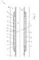
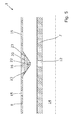
- Fig. 1 shows a downhole fluid injection assembly 1 for injecting a treatment fluid 5, illustrated by arrows, into an annulus 3 surrounding a well casing 2.
- the downhole fluid injection assembly comprises a tubular part 7 for mounting as part of the well casing and a sleeve 8 surrounding the tubular part.
- the sleeve has a first end 9 and a second end 10 and is at its ends connected with the tubular part, thereby defining an annular space 11 between the sleeve and the tubular part.
- the annular space is brought into fluid communication with an inside 14 of the tubular part by means of the aperture 12 arranged in the tubular part.
- the sleeve has openings 15 arranged in the sleeve for bringing the annular space into fluid communication with the annulus.
- the aperture 12 is arranged opposite the sleeve 8, and the space 11 and the openings 15 in the sleeve distribute the treatment fluid 5 in such a way that only part of the treatment fluid is injected directly into the annulus 3 opposite the aperture, corroding merely one large hole in the formation 21.
- the treatment fluid 5 is distributed along a longitudinal axis of the assembly and along a circumference of the sleeve 8.
- the fluid 5 is distributed over a wider range than in prior art injection systems, thereby corroding a wider area of the formation 21.
- the sleeve 8 has an increased thickness at its ends 9, 10 for fastening the sleeve to an outside the tubular part 7 while providing the annular space 11 opposite the thinner part of the sleeve.
- the ends 9, 10 of the sleeve 8 may be welded onto the tubular part 7 or tightly fitted around the tubular part.
- the annular space 11 functions as a distributing channel distributing the treatment fluid in such a way that it flows through all the openings 15 in the sleeve 8, as illustrated by arrows in Fig. 1 .
- the treatment fluid 5 is thus distributed along the longitudinal axis and along the circumference of the sleeve 8.
- the sleeve 8 comprises a sleeve section 16 arranged between two adjacent openings 15, and the aperture 12 is arranged opposite the sleeve section so as to ensure that the treatment fluid 5 is not distributed directly into an opening but is forced towards both ends 9, 10 of the sleeve.
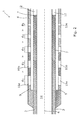
- a first opening 15a of the sleeve 8 arranged closest to one of the ends is larger than a second opening 15b of the sleeve to be able to distribute the treatment fluid even better than the sleeve of Fig. 1 .
- the pressure drops across the annular space, and by providing the sleeve 8 with larger openings near its ends, more treatment fluid is let out of the first opening.
- the pressure of the treatment fluid near he ends of the sleeve 8 is lower than that of the fluid injected through the openings closer to the aperture 12.
- each opening 15a, 15b has a size d which increases towards at least one of the ends of the sleeve 8.
- the opening 15 closest to one of the ends may be at least 20% larger than the opening closest to the aperture 12, preferably at least 30%, and more preferably at least 40%.
- the openings 15 arranged between the opening closest to the one end and the opening closest to the aperture vary in size between the size of the first opening 15a and the opening 15e closest to the aperture.
- the openings 15 are arranged with a mutual distance x along the longitudinal axis 6.
- the distance between the openings 15 decreases towards at least one of the ends of the sleeve 8 so that the openings are arranged more closely near the ends of the sleeve than near the aperture 12 of the tubular part 7.
- the distance between a couple of adjacent openings may be the same, e.g. near the ends of the sleeve, while the distance between the next openings increases towards the aperture 12.
- the sleeve section 16 of Fig. 4 tapers radially towards the aperture 12, and the sleeve 8 is thus thicker opposite the aperture.
- the treatment fluid is diverted from flowing radially to flowing axially towards the ends of the sleeve 8.
- the sleeve section 16 may be pushed radially inwards during installation of the downhole fluid injection assembly 1 so that the sleeve section 16 covers the aperture 12.
- the sleeve section 16 is therefore provided with flow channels 20 enabling the treatment fluid to push the sleeve section radially outwards and to initiate distribution of the treatment fluid along the annular space 11.
- the sleeve section 16 has a round shape when seen in cross-section, and in Fig. 5 showing another embodiment of the sleeve section, the sleeve section has a more triangular cross-sectional shape.
- the flow channel 20 in the embodiments of Figs. 4 and 5 has an inlet 22 arranged opposite the aperture 12 and outlets 23 facing the ends of the sleeve 8.
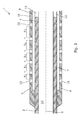
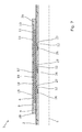
- the downhole fluid injection assembly further comprises a spacing element 17 arranged in the annular space 11, as shown in Fig. 6 .
- the spacing element 17 is arranged in the annular space 11 to minimise the risk of the sleeve being pressed up against the tubular part 7 and to ensure that the annular space stays intact to enable the treatment fluid to flow in the annular space.
- the downhole fluid injection assembly 1 is shown with the sleeve 8 partly removed to make the spacing elements 17 visible.
- the sleeve covers the spacing elements 17 and the apertures 12, and the spacing elements 17 is fastened to an outer face 24 of the tubular part 7 extending along the longitudinal axis of the downhole fluid injection assembly 1.
- the sleeve comprises a plurality of openings 15 arranged in a predetermined pattern.
- the spacing element 17 may taper towards at least one of the ends of the sleeve, and one spacing element extends from the sleeve section 16 towards the one end of the sleeve while another spacing element extends from the sleeve section 16 towards the other end of the sleeve.
- the spacing element 17 may also be a helical string or rod wound around the tubular part 7 within the space 11.
- the downhole fluid injection assembly 1 comprises a plurality of balls 18 arranged in the annular space 11.
- the balls 18 function as spacing elements in that they prevent the sleeve 8 from bulging radially inwards.
- the spacing elements 17 and/or the balls 18 are made of a corrodible material, such as aluminium, but may also be made of a ceramic material.
- the acid corrodes the spacing elements 17 and/or the balls 18, allowing the fluid to flow freely in the space 11.
- the pressure is no longer decreased as much as when the spacing elements 17 and/or the balls 18 are still in the space 11.
- the tubular part 7 comprises a plurality of apertures 12 arranged opposite the sleeve 8.
- the apertures 12 have a mutual distance along the longitudinal axis 6.
- the apertures are closable by means of a sliding sleeve 26 sliding in a groove 27 in the tubular part 7.
- the downhole fluid injection assembly 1 can be closed off, e.g. while pressurising the casing for inflating/expanding other components, such as a packer or an annular barrier.
- the sleeve 8 is fastened to the tubular part 7 by means of two connection parts 28.
- the sleeve 8 may be fastened in the connection parts 28 by means of a threaded or welded connection.
- the sleeve 8 and the tubular part 7 may be made of an acid-resistant metal.
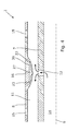
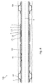
- Fig. 8 shows a downhole casing system 100 comprising a casing string 2, the downhole fluid injection assembly 1 described above and a first and a second annular barrier 50 each mounted as part of the casing string on opposite sides of the fluid injection assembly enclosing a production zone.
- the downhole casing system 100 further comprises an inflow section 60 mounted as part of the casing string between the first and second annular barriers for letting hydrocarbon-containing fluid into the casing after the treatment of the formation has ended.
- the inflow section 60 comprises a screen or a filtering element ensuring that only oil and gas is let into the casing. After passing the screen or filter, the hydrocarbon-containing fluid is let into inflow channels, out through a valve 61 and into the casing.
- the annular barriers comprise en expandable sleeve which, prior to injection of treatment fluid, is expanded, thereby isolating the annulus surrounding the fluid injection assembly 1. Then, the treatment fluid is let into the annular space of the downhole fluid injection assembly 1 via the aperture 12 in the tubular part 7 and is distributed along the longitudinal axis of the fluid injection assembly and let out through the openings 15 to treat the annulus.
- well fluid any kind of fluid that may be present in oil or gas wells downhole, such as natural gas, oil, oil mud, crude oil, water, etc.
- gas any kind of gas composition present in a well, completion, or open hole
- oil any kind of oil composition, such as crude oil, an oil-containing fluid, etc.
- Gas, oil, and water fluids may thus all comprise other elements or substances than gas, oil, and/or water, respectively.
- treatment fluid any kind of fluid for treating the formation or reservoir to help the hydrocarbon-containing fluid, such as oil or gas, flow easier.
- the treament fluid may be any kind of acid, such as HCl, H 2 S or H 2 SO 4 or any combination thereof.
- the treatment fluid may also comprise proppants.
- a casing any kind of pipe, tubing, tubular, liner, string etc. used downhole in relation to oil or natural gas production.
Abstract
A downhole fluid injection assembly (1) for injecting a treatment fluid (5) into an annulus (3) surrounding a well casing (2), the downhole fluid injection assembly having a longitudinal axis (6) and comprising: - a tubular part (7) for mounting as part of the well casing, - a sleeve (8) having a first end (9) and a second end (10), the sleeve surrounding the tubular part, and the first and second ends being connected with the tubular part and defining a space (11), - an aperture (12) arranged in the tubular part for bringing an inside (14) of the tubular part into fluid communication with the space, and - openings (15) arranged in the sleeve for bringing the space into fluid communication with the annulus, wherein the aperture is arranged opposite the sleeve.
Description
- The present invention relates to a downhole fluid injection assembly for injecting a treatment fluid into an annulus surrounding a well casing. The invention furthermore relates to a downhole casing system and a method for treating an annulus by means of the fluid injection assembly.
- After completing a well, the hydrocarbon-containing fluid in the reservoir does not always flow out of the reservoir at a sufficiently high volume rate, and the formation is therefore treated to increase the volume rate of the fluid. One way of treating the formation is by injecting acid through the openings in the casing at a high velocity. However, this is not always sufficient to obtain the desired flow, and there is therefore a need for a more efficient way of treating the formation.
- It is an object of the present invention to wholly or partly overcome the above disadvantages and drawbacks of the prior art. More specifically, it is an object to provide an improved fluid injection system which provides a more efficient way of treating a formation.
- The above objects, together with numerous other objects, advantages, and features, which will become evident from the below description, are accomplished by a solution in accordance with the present invention by a downhole fluid injection assembly for injecting a treatment fluid into an annulus surrounding a well casing, the downhole fluid injection assembly having a longitudinal axis and comprising:
- a tubular part for mounting as part of the well casing,
- a sleeve having a first end and a second end, the sleeve surrounding the tubular part, and the first and second ends being connected with the tubular part and defining a space,
- an aperture arranged in the tubular part for bringing an inside of the tubular part into fluid communication with the space, and
- openings arranged in the sleeve for bringing the space into fluid communication with the annulus,
- In an embodiment, the sleeve may comprise a first opening and a second opening, the first opening being arranged closest to one of the ends and being larger than the second opening.
- Furthermore, the sleeve may comprise a sleeve section arranged between two adjacent openings, and the aperture may be arranged opposite the sleeve section.
- Moreover, the sleeve section may taper radially towards the aperture.
- Also, the sleeve section may have at least one flow channel.
- The downhole fluid injection assembly may further comprise a spacing element arranged in the space.
- The spacing element is arranged in the space to minimise the risk of the sleeve being pressed up against the tubular part so as to ensure that the space stays intact to enable the treatment fluid to flow in the space.
- In one embodiment, the spacing element may taper towards at least one of the ends of the sleeve.
- Further, a plurality of spacing elements may be arranged along the first axis.
- Additionally, a plurality of spacing elements may be arranged in the space around a circumferential extension thereof.
- Moreover, the spacing element may comprise a helical string or rod wound around the tubular part within the space.
- Also, the spacing elements may be a plurality of balls arranged in the space.
- In addition, the spacing elements and/or the balls may be made of a corrodible material.
- Furthermore, the openings may be arranged in a predetermined pattern.
- Moreover, the openings may be arranged with a mutual distance along the longitudinal axis.
- Additionally, the mutual distance may decrease towards at least one of the ends of the sleeve.
- In an embodiment, the distance between the openings may decrease towards at least one of the ends of the sleeve.
- In another embodiment, each opening may have a size which increases towards at least one of the ends of the sleeve.
- In yet another embodiment, the opening closest to one of the ends may be at least 20% larger than the opening closest to the aperture, preferably at least 30%, and more preferably at least 40%.
- Furthermore, a plurality of apertures may be arranged opposite the sleeve.
- Also, the apertures may have a mutual distance along the longitudinal axis.
- In addition, the aperture may be closable.
- Further, the treatment fluid may be an acid or a mixture of acids.
- Additionally, the sleeve may be made of an acid-resistant metal.
- The present relation further relates to a downhole casing system comprising:
- a casing string,
- a fluid injection assembly according to any of the preceding claims, the tubular part thereof being mounted as part of the casing string, and
- a first and a second annular barrier each mounted as part of the casing string on opposite sides of the fluid injection assembly.
- The downhole casing system may further comprise an inflow section mounted as part of the casing string between the first and second annular barriers.
- Finally, the present invention relates to a method for treating an annulus by means of the fluid injection assembly as described above, the method comprising the steps of:
- isolating the annulus surrounding the fluid injection assembly by means of the annular barriers,
- letting treatment fluid into the space via the aperture,
- distributing the treatment fluid along the longitudinal axis of the fluid injection assembly, and
- letting the treatment fluid out through the openings in order to treat the annulus.
- The method may further comprise the step of corroding the corrodible spacing element or balls in the space.
- The invention and its many advantages will be described in more detail below with reference to the accompanying schematic drawings, which for the purpose of illustration show some non-limiting embodiments and in which
-
Fig. 1 shows a cross-sectional view of a downhole fluid injection assembly according to the present invention, -
Fig. 2 shows a cross-sectional view of part of another downhole fluid injection assembly, -
Fig. 3 shows a cross-sectional view of part of yet another downhole fluid injection assembly, -
Fig. 4 shows a cross-sectional view of part of a sleeve section of another downhole fluid injection assembly, -
Fig. 5 shows a cross-sectional view of part of another embodiment of the sleeve section of another downhole fluid injection assembly, -
Fig. 6 shows a perspective view of a downhole fluid injection assembly in which part of the sleeve has been removed for illustrative purposes, -
Fig. 7 shows a cross-sectional view of part of yet another downhole fluid injection assembly, and -
Fig. 8 shows a cross-sectional view of a downhole casing system according to the invention. - All the figures are highly schematic and not necessarily to scale, and they show only those parts which are necessary in order to elucidate the invention, other parts being omitted or merely suggested.
-
Fig. 1 shows a downholefluid injection assembly 1 for injecting atreatment fluid 5, illustrated by arrows, into anannulus 3 surrounding awell casing 2. When completing the well, the production zones are subsequently treated with acid injected from the casing through anaperture 12 arranged therein, through the downholefluid injection assembly 1 and into the annulus. The downhole fluid injection assembly comprises atubular part 7 for mounting as part of the well casing and asleeve 8 surrounding the tubular part. The sleeve has afirst end 9 and asecond end 10 and is at its ends connected with the tubular part, thereby defining anannular space 11 between the sleeve and the tubular part. The annular space is brought into fluid communication with an inside 14 of the tubular part by means of theaperture 12 arranged in the tubular part. The sleeve hasopenings 15 arranged in the sleeve for bringing the annular space into fluid communication with the annulus. Theaperture 12 is arranged opposite thesleeve 8, and thespace 11 and theopenings 15 in the sleeve distribute thetreatment fluid 5 in such a way that only part of the treatment fluid is injected directly into theannulus 3 opposite the aperture, corroding merely one large hole in theformation 21. By the present invention, thetreatment fluid 5 is distributed along a longitudinal axis of the assembly and along a circumference of thesleeve 8. Thus, thefluid 5 is distributed over a wider range than in prior art injection systems, thereby corroding a wider area of theformation 21. - The
sleeve 8 has an increased thickness at itsends tubular part 7 while providing theannular space 11 opposite the thinner part of the sleeve. The ends 9, 10 of thesleeve 8 may be welded onto thetubular part 7 or tightly fitted around the tubular part. Theannular space 11 functions as a distributing channel distributing the treatment fluid in such a way that it flows through all theopenings 15 in thesleeve 8, as illustrated by arrows inFig. 1 . Thetreatment fluid 5 is thus distributed along the longitudinal axis and along the circumference of thesleeve 8. Thesleeve 8 comprises asleeve section 16 arranged between twoadjacent openings 15, and theaperture 12 is arranged opposite the sleeve section so as to ensure that thetreatment fluid 5 is not distributed directly into an opening but is forced towards both ends 9, 10 of the sleeve. - In
Fig. 2 , afirst opening 15a of thesleeve 8 arranged closest to one of the ends is larger than asecond opening 15b of the sleeve to be able to distribute the treatment fluid even better than the sleeve ofFig. 1 . The pressure drops across the annular space, and by providing thesleeve 8 with larger openings near its ends, more treatment fluid is let out of the first opening. The pressure of the treatment fluid near he ends of thesleeve 8 is lower than that of the fluid injected through the openings closer to theaperture 12. Thus, by varying the size of the openings, substantially the same volume flow of the treatment fluid entering through all openings in the sleeve is obtained. The diameter d1 of thefirst opening 15a is larger than the diameter d2 of thesecond opening 15b and so forth. Thus, eachopening sleeve 8. Theopening 15 closest to one of the ends may be at least 20% larger than the opening closest to theaperture 12, preferably at least 30%, and more preferably at least 40%. Theopenings 15 arranged between the opening closest to the one end and the opening closest to the aperture vary in size between the size of thefirst opening 15a and theopening 15e closest to the aperture. - As shown in
Fig. 3 , theopenings 15 are arranged with a mutual distance x along thelongitudinal axis 6. The distance between theopenings 15 decreases towards at least one of the ends of thesleeve 8 so that the openings are arranged more closely near the ends of the sleeve than near theaperture 12 of thetubular part 7. Even though not shown, the distance between a couple of adjacent openings may be the same, e.g. near the ends of the sleeve, while the distance between the next openings increases towards theaperture 12. - The
sleeve section 16 ofFig. 4 tapers radially towards theaperture 12, and thesleeve 8 is thus thicker opposite the aperture. By having a tapering sleeve section, the treatment fluid is diverted from flowing radially to flowing axially towards the ends of thesleeve 8. Before initiating the injection process, thesleeve section 16 may be pushed radially inwards during installation of the downholefluid injection assembly 1 so that thesleeve section 16 covers theaperture 12. Thesleeve section 16 is therefore provided withflow channels 20 enabling the treatment fluid to push the sleeve section radially outwards and to initiate distribution of the treatment fluid along theannular space 11. InFig. 4 , thesleeve section 16 has a round shape when seen in cross-section, and inFig. 5 showing another embodiment of the sleeve section, the sleeve section has a more triangular cross-sectional shape. Theflow channel 20 in the embodiments ofFigs. 4 and5 has aninlet 22 arranged opposite theaperture 12 andoutlets 23 facing the ends of thesleeve 8. - In order to prevent the sleeve from bulging radially inwards during insertion of the downhole
fluid injection assembly 1, the downhole fluid injection assembly further comprises aspacing element 17 arranged in theannular space 11, as shown inFig. 6 . Thus, thespacing element 17 is arranged in theannular space 11 to minimise the risk of the sleeve being pressed up against thetubular part 7 and to ensure that the annular space stays intact to enable the treatment fluid to flow in the annular space. The downholefluid injection assembly 1 is shown with thesleeve 8 partly removed to make thespacing elements 17 visible. Thus, the sleeve covers thespacing elements 17 and theapertures 12, and thespacing elements 17 is fastened to anouter face 24 of thetubular part 7 extending along the longitudinal axis of the downholefluid injection assembly 1. As can be seen, the sleeve comprises a plurality ofopenings 15 arranged in a predetermined pattern. - In one embodiment, the
spacing element 17 may taper towards at least one of the ends of the sleeve, and one spacing element extends from thesleeve section 16 towards the one end of the sleeve while another spacing element extends from thesleeve section 16 towards the other end of the sleeve. Thus, there is nospacing element 17 opposite the apertures, and the treatment fluid can therefore be distributed along the annular part of the space and flow in through all channels provided by the spacing elements. - The
spacing element 17 may also be a helical string or rod wound around thetubular part 7 within thespace 11. - In
Fig. 7 , the downholefluid injection assembly 1 comprises a plurality ofballs 18 arranged in theannular space 11. Theballs 18 function as spacing elements in that they prevent thesleeve 8 from bulging radially inwards. Thespacing elements 17 and/or theballs 18 are made of a corrodible material, such as aluminium, but may also be made of a ceramic material. By having thespacing elements 17 and/or theballs 18 made of a corrodible material, the acid corrodes thespacing elements 17 and/or theballs 18, allowing the fluid to flow freely in thespace 11. Thus, the pressure is no longer decreased as much as when thespacing elements 17 and/or theballs 18 are still in thespace 11. - In
Fig. 7 , thetubular part 7 comprises a plurality ofapertures 12 arranged opposite thesleeve 8. Theapertures 12 have a mutual distance along thelongitudinal axis 6. The apertures are closable by means of a slidingsleeve 26 sliding in agroove 27 in thetubular part 7. Before or after the treatment process, i.e. the injection, the downholefluid injection assembly 1 can be closed off, e.g. while pressurising the casing for inflating/expanding other components, such as a packer or an annular barrier. Furthermore, thesleeve 8 is fastened to thetubular part 7 by means of twoconnection parts 28. Thesleeve 8 may be fastened in theconnection parts 28 by means of a threaded or welded connection. - When the
treatment fluid 5 is acid, thesleeve 8 and thetubular part 7 may be made of an acid-resistant metal. -
Fig. 8 shows adownhole casing system 100 comprising acasing string 2, the downholefluid injection assembly 1 described above and a first and a secondannular barrier 50 each mounted as part of the casing string on opposite sides of the fluid injection assembly enclosing a production zone. Thedownhole casing system 100 further comprises aninflow section 60 mounted as part of the casing string between the first and second annular barriers for letting hydrocarbon-containing fluid into the casing after the treatment of the formation has ended. Theinflow section 60 comprises a screen or a filtering element ensuring that only oil and gas is let into the casing. After passing the screen or filter, the hydrocarbon-containing fluid is let into inflow channels, out through avalve 61 and into the casing. The annular barriers comprise en expandable sleeve which, prior to injection of treatment fluid, is expanded, thereby isolating the annulus surrounding thefluid injection assembly 1. Then, the treatment fluid is let into the annular space of the downholefluid injection assembly 1 via theaperture 12 in thetubular part 7 and is distributed along the longitudinal axis of the fluid injection assembly and let out through theopenings 15 to treat the annulus. - By well fluid is meant any kind of fluid that may be present in oil or gas wells downhole, such as natural gas, oil, oil mud, crude oil, water, etc. By gas is meant any kind of gas composition present in a well, completion, or open hole, and by oil is meant any kind of oil composition, such as crude oil, an oil-containing fluid, etc. Gas, oil, and water fluids may thus all comprise other elements or substances than gas, oil, and/or water, respectively.
- By treatment fluid is meant any kind of fluid for treating the formation or reservoir to help the hydrocarbon-containing fluid, such as oil or gas, flow easier. The treament fluid may be any kind of acid, such as HCl, H2S or H2SO4 or any combination thereof. The treatment fluid may also comprise proppants.
- By a casing is meant any kind of pipe, tubing, tubular, liner, string etc. used downhole in relation to oil or natural gas production.
- Although the invention has been described in the above in connection with preferred embodiments of the invention, it will be evident for a person skilled in the art that several modifications are conceivable without departing from the invention as defined by the following claims.
Claims (15)
- A downhole fluid injection assembly (1) for injecting a treatment fluid (5) into an annulus (3) surrounding a well casing (2), the downhole fluid injection assembly having a longitudinal axis (6) and comprising:- a tubular part (7) for mounting as part of the well casing,- a sleeve (8) having a first end (9) and a second end (10), the sleeve surrounding the tubular part, and the first and second ends being connected with the tubular part and defining a space (11),- an aperture (12) arranged in the tubular part for bringing an inside (14) of the tubular part into fluid communication with the space, and- openings (15) arranged in the sleeve for bringing the space into fluid communication with the annulus,
wherein the aperture is arranged opposite the sleeve. - A downhole fluid injection assembly according to claim 1, wherein the sleeve comprises a first opening (15a) and a second opening (15b), the first opening being arranged closest to one of the ends and being larger than the second opening.
- A downhole fluid injection assembly according to claim(s) 1 and/or 2, wherein the sleeve comprises a sleeve section (16) arranged between two adjacent openings and the aperture is arranged opposite the sleeve section.
- A downhole fluid injection assembly according to claim 3, wherein the sleeve section tapers radially towards the aperture.
- A downhole fluid injection assembly according to any of the preceding claims, further comprising a spacing element (17) arranged in the space.
- A downhole fluid injection assembly according to claim 5, wherein the spacing element tapers towards at least one of the ends of the sleeve.
- A downhole fluid injection assembly according to claim 5, wherein the spacing elements are a plurality of balls (18) arranged in the space.
- A downhole fluid injection assembly according any of the claims 5-7, wherein the spacing elements and/or the balls are made of a corrodible material.
- A downhole fluid injection assembly according to any of the preceding claims, wherein the openings are arranged with a mutual distance (x) along the longitudinal axis, which distance decreases towards at least one of the ends of the sleeve.
- A downhole fluid injection assembly according to any of the claims 1-8, wherein the distance between the openings decreases towards at least one of the ends of the sleeve.
- A downhole fluid injection assembly according to any of the preceding claims, wherein each opening has a size (d) which increases towards at least one of the ends of the sleeve.
- A downhole casing system (100) comprising:- a casing string (2),- a fluid injection assembly (1) according to any of the preceding claims, the tubular part thereof being mounted as part of the casing string, and- a first and a second annular barrier (50) each mounted as part of the casing string on opposite sides of the fluid injection assembly.
- A downhole casing system according to claim 12, further comprising an inflow section (60) mounted as part of the casing string between the first and second annular barriers.
- A method for treating an annulus by means of the fluid injection assembly according to any of the claims 1 to 11, the method comprising the steps of:- isolating the annulus surrounding the fluid injection assembly by means of the annular barriers,- letting treatment fluid into the space via the aperture,- distributing the treatment fluid along the longitudinal axis of the fluid injection assembly, and- letting the treatment fluid out through the openings in order to treat the annulus.
- A method according to claim 14, further comprising the step of corroding the corrodible spacing element or balls in the space.
Priority Applications (1)
| Application Number | Priority Date | Filing Date | Title |
|---|---|---|---|
| EP12196093.4A EP2740887A1 (en) | 2012-12-07 | 2012-12-07 | A downhole fluid injection assembly and a downhole casing system |
Applications Claiming Priority (1)
| Application Number | Priority Date | Filing Date | Title |
|---|---|---|---|
| EP12196093.4A EP2740887A1 (en) | 2012-12-07 | 2012-12-07 | A downhole fluid injection assembly and a downhole casing system |
Publications (1)
| Publication Number | Publication Date |
|---|---|
| EP2740887A1 true EP2740887A1 (en) | 2014-06-11 |
Family
ID=47290827
Family Applications (1)
| Application Number | Title | Priority Date | Filing Date |
|---|---|---|---|
| EP12196093.4A Withdrawn EP2740887A1 (en) | 2012-12-07 | 2012-12-07 | A downhole fluid injection assembly and a downhole casing system |
Country Status (1)
| Country | Link |
|---|---|
| EP (1) | EP2740887A1 (en) |
Cited By (1)
| Publication number | Priority date | Publication date | Assignee | Title |
|---|---|---|---|---|
| US20160237792A1 (en) * | 2015-02-17 | 2016-08-18 | Weatherford Technology Holdings, Llc | Injection distribution device |
Citations (5)
| Publication number | Priority date | Publication date | Assignee | Title |
|---|---|---|---|---|
| US5165476A (en) * | 1991-06-11 | 1992-11-24 | Mobil Oil Corporation | Gravel packing of wells with flow-restricted screen |
| US20020125006A1 (en) * | 2001-03-06 | 2002-09-12 | Hailey Travis T. | Apparatus and method for gravel packing an interval of a wellbore |
| US20020189809A1 (en) * | 2001-06-13 | 2002-12-19 | Nguyen Philip D. | Methods and apparatus for gravel packing, fracturing or frac packing wells |
| US20030066651A1 (en) * | 2001-10-09 | 2003-04-10 | Johnson Craig David | Apparatus and methods for flow control gravel pack |
| US20030221828A1 (en) * | 2002-05-31 | 2003-12-04 | Mcgregor Ronald W. | Apparatus and method for gravel packing an interval of a wellbore |
-
2012
- 2012-12-07 EP EP12196093.4A patent/EP2740887A1/en not_active Withdrawn
Patent Citations (5)
| Publication number | Priority date | Publication date | Assignee | Title |
|---|---|---|---|---|
| US5165476A (en) * | 1991-06-11 | 1992-11-24 | Mobil Oil Corporation | Gravel packing of wells with flow-restricted screen |
| US20020125006A1 (en) * | 2001-03-06 | 2002-09-12 | Hailey Travis T. | Apparatus and method for gravel packing an interval of a wellbore |
| US20020189809A1 (en) * | 2001-06-13 | 2002-12-19 | Nguyen Philip D. | Methods and apparatus for gravel packing, fracturing or frac packing wells |
| US20030066651A1 (en) * | 2001-10-09 | 2003-04-10 | Johnson Craig David | Apparatus and methods for flow control gravel pack |
| US20030221828A1 (en) * | 2002-05-31 | 2003-12-04 | Mcgregor Ronald W. | Apparatus and method for gravel packing an interval of a wellbore |
Cited By (1)
| Publication number | Priority date | Publication date | Assignee | Title |
|---|---|---|---|---|
| US20160237792A1 (en) * | 2015-02-17 | 2016-08-18 | Weatherford Technology Holdings, Llc | Injection distribution device |
Similar Documents
| Publication | Publication Date | Title |
|---|---|---|
| US20140305630A1 (en) | Flow Control Screen Assembly Having an Adjustable Inflow Control Device | |
| US20140060837A1 (en) | Method and apparatus for treating a well | |
| RU2639344C2 (en) | Well expanding pipe | |
| EP2644819A1 (en) | An annular barrier having expansion tubes | |
| US9163494B2 (en) | Method and apparatus for treating a well | |
| CN103874827A (en) | Fluid filtering device for a wellbore and method for completing a wellbore | |
| CA2916646C (en) | Flow control devices including a sand screen and an inflow control device for use in wellbores | |
| CA2975736C (en) | Temporarily impermeable sleeve for running a well component in hole | |
| US20170122081A1 (en) | Systems And Methods To Reduce Erosion In Wire Wrap Screen On Perforated Base Pipe | |
| RU2622572C2 (en) | Borehole cavity stabilization method | |
| US10208571B2 (en) | Flow conditioning flow control device | |
| RU2718897C2 (en) | Well completion system | |
| EP2740887A1 (en) | A downhole fluid injection assembly and a downhole casing system | |
| AU2013385834B2 (en) | Flow control screen assembly having an adjustable inflow control device | |
| CN103628845A (en) | Novel stereo sand control screen | |
| US9896905B2 (en) | Inflow control system for use in a wellbore | |
| EP2350435A1 (en) | Well liner segments for in situ petroleum upgrading and recovery, and method of in situ upgrading and recovery | |
| WO2016028414A1 (en) | Bidirectional flow control device for facilitating stimulation treatments in a subterranean formation | |
| US10408022B2 (en) | Enhanced erosion resistance wire shapes | |
| US10041336B2 (en) | Crimped nozzle for alternate path well screen | |
| US10677013B2 (en) | Annular barrier with shunt tube | |
| RU2619615C1 (en) | Expandable well filter and method of its installation | |
| CN203488159U (en) | Novel three-dimensional sand control screen | |
| WO2019068164A1 (en) | Flow control apparatus for wellbore stimulation and production | |
| RU2405922C1 (en) | Well filter |
Legal Events
| Date | Code | Title | Description |
|---|---|---|---|
| PUAI | Public reference made under article 153(3) epc to a published international application that has entered the european phase |
Free format text: ORIGINAL CODE: 0009012 |
|
| 17P | Request for examination filed |
Effective date: 20121207 |
|
| AK | Designated contracting states |
Kind code of ref document: A1 Designated state(s): AL AT BE BG CH CY CZ DE DK EE ES FI FR GB GR HR HU IE IS IT LI LT LU LV MC MK MT NL NO PL PT RO RS SE SI SK SM TR |
|
| AX | Request for extension of the european patent |
Extension state: BA ME |
|
| STAA | Information on the status of an ep patent application or granted ep patent |
Free format text: STATUS: THE APPLICATION IS DEEMED TO BE WITHDRAWN |
|
| 18D | Application deemed to be withdrawn |
Effective date: 20141212 |