EP2743132A1 - Driver vision support system - Google Patents
Driver vision support system Download PDFInfo
- Publication number
- EP2743132A1 EP2743132A1 EP12008321.7A EP12008321A EP2743132A1 EP 2743132 A1 EP2743132 A1 EP 2743132A1 EP 12008321 A EP12008321 A EP 12008321A EP 2743132 A1 EP2743132 A1 EP 2743132A1
- Authority
- EP
- European Patent Office
- Prior art keywords
- camera
- support system
- agricultural machine
- driver
- vision support
- Prior art date
- Legal status (The legal status is an assumption and is not a legal conclusion. Google has not performed a legal analysis and makes no representation as to the accuracy of the status listed.)
- Granted
Links
- 230000000007 visual effect Effects 0.000 claims abstract description 7
- 239000004459 forage Substances 0.000 description 2
- SAZUGELZHZOXHB-UHFFFAOYSA-N acecarbromal Chemical compound CCC(Br)(CC)C(=O)NC(=O)NC(C)=O SAZUGELZHZOXHB-UHFFFAOYSA-N 0.000 description 1
- 239000000853 adhesive Substances 0.000 description 1
- 230000001070 adhesive effect Effects 0.000 description 1
- 238000006243 chemical reaction Methods 0.000 description 1
- 230000008030 elimination Effects 0.000 description 1
- 238000003379 elimination reaction Methods 0.000 description 1
- 238000009313 farming Methods 0.000 description 1
- 238000009434 installation Methods 0.000 description 1
- 230000010354 integration Effects 0.000 description 1
- 238000000034 method Methods 0.000 description 1
- 238000005096 rolling process Methods 0.000 description 1
Images
Classifications
-
- A—HUMAN NECESSITIES
- A01—AGRICULTURE; FORESTRY; ANIMAL HUSBANDRY; HUNTING; TRAPPING; FISHING
- A01B—SOIL WORKING IN AGRICULTURE OR FORESTRY; PARTS, DETAILS, OR ACCESSORIES OF AGRICULTURAL MACHINES OR IMPLEMENTS, IN GENERAL
- A01B69/00—Steering of agricultural machines or implements; Guiding agricultural machines or implements on a desired track
- A01B69/001—Steering by means of optical assistance, e.g. television cameras
-
- H—ELECTRICITY
- H04—ELECTRIC COMMUNICATION TECHNIQUE
- H04N—PICTORIAL COMMUNICATION, e.g. TELEVISION
- H04N23/00—Cameras or camera modules comprising electronic image sensors; Control thereof
- H04N23/60—Control of cameras or camera modules
- H04N23/63—Control of cameras or camera modules by using electronic viewfinders
-
- A—HUMAN NECESSITIES
- A01—AGRICULTURE; FORESTRY; ANIMAL HUSBANDRY; HUNTING; TRAPPING; FISHING
- A01B—SOIL WORKING IN AGRICULTURE OR FORESTRY; PARTS, DETAILS, OR ACCESSORIES OF AGRICULTURAL MACHINES OR IMPLEMENTS, IN GENERAL
- A01B76/00—Parts, details or accessories of agricultural machines or implements, not provided for in groups A01B51/00 - A01B75/00
-
- B—PERFORMING OPERATIONS; TRANSPORTING
- B60—VEHICLES IN GENERAL
- B60R—VEHICLES, VEHICLE FITTINGS, OR VEHICLE PARTS, NOT OTHERWISE PROVIDED FOR
- B60R1/00—Optical viewing arrangements; Real-time viewing arrangements for drivers or passengers using optical image capturing systems, e.g. cameras or video systems specially adapted for use in or on vehicles
- B60R1/20—Real-time viewing arrangements for drivers or passengers using optical image capturing systems, e.g. cameras or video systems specially adapted for use in or on vehicles
- B60R1/22—Real-time viewing arrangements for drivers or passengers using optical image capturing systems, e.g. cameras or video systems specially adapted for use in or on vehicles for viewing an area outside the vehicle, e.g. the exterior of the vehicle
- B60R1/23—Real-time viewing arrangements for drivers or passengers using optical image capturing systems, e.g. cameras or video systems specially adapted for use in or on vehicles for viewing an area outside the vehicle, e.g. the exterior of the vehicle with a predetermined field of view
- B60R1/25—Real-time viewing arrangements for drivers or passengers using optical image capturing systems, e.g. cameras or video systems specially adapted for use in or on vehicles for viewing an area outside the vehicle, e.g. the exterior of the vehicle with a predetermined field of view to the sides of the vehicle
-
- B—PERFORMING OPERATIONS; TRANSPORTING
- B60—VEHICLES IN GENERAL
- B60R—VEHICLES, VEHICLE FITTINGS, OR VEHICLE PARTS, NOT OTHERWISE PROVIDED FOR
- B60R1/00—Optical viewing arrangements; Real-time viewing arrangements for drivers or passengers using optical image capturing systems, e.g. cameras or video systems specially adapted for use in or on vehicles
- B60R1/20—Real-time viewing arrangements for drivers or passengers using optical image capturing systems, e.g. cameras or video systems specially adapted for use in or on vehicles
- B60R1/22—Real-time viewing arrangements for drivers or passengers using optical image capturing systems, e.g. cameras or video systems specially adapted for use in or on vehicles for viewing an area outside the vehicle, e.g. the exterior of the vehicle
- B60R1/23—Real-time viewing arrangements for drivers or passengers using optical image capturing systems, e.g. cameras or video systems specially adapted for use in or on vehicles for viewing an area outside the vehicle, e.g. the exterior of the vehicle with a predetermined field of view
- B60R1/26—Real-time viewing arrangements for drivers or passengers using optical image capturing systems, e.g. cameras or video systems specially adapted for use in or on vehicles for viewing an area outside the vehicle, e.g. the exterior of the vehicle with a predetermined field of view to the rear of the vehicle
-
- B—PERFORMING OPERATIONS; TRANSPORTING
- B60—VEHICLES IN GENERAL
- B60R—VEHICLES, VEHICLE FITTINGS, OR VEHICLE PARTS, NOT OTHERWISE PROVIDED FOR
- B60R1/00—Optical viewing arrangements; Real-time viewing arrangements for drivers or passengers using optical image capturing systems, e.g. cameras or video systems specially adapted for use in or on vehicles
- B60R1/12—Mirror assemblies combined with other articles, e.g. clocks
- B60R2001/1253—Mirror assemblies combined with other articles, e.g. clocks with cameras, video cameras or video screens
-
- B—PERFORMING OPERATIONS; TRANSPORTING
- B60—VEHICLES IN GENERAL
- B60R—VEHICLES, VEHICLE FITTINGS, OR VEHICLE PARTS, NOT OTHERWISE PROVIDED FOR
- B60R2300/00—Details of viewing arrangements using cameras and displays, specially adapted for use in a vehicle
- B60R2300/10—Details of viewing arrangements using cameras and displays, specially adapted for use in a vehicle characterised by the type of camera system used
- B60R2300/101—Details of viewing arrangements using cameras and displays, specially adapted for use in a vehicle characterised by the type of camera system used using cameras with adjustable capturing direction
-
- B—PERFORMING OPERATIONS; TRANSPORTING
- B60—VEHICLES IN GENERAL
- B60R—VEHICLES, VEHICLE FITTINGS, OR VEHICLE PARTS, NOT OTHERWISE PROVIDED FOR
- B60R2300/00—Details of viewing arrangements using cameras and displays, specially adapted for use in a vehicle
- B60R2300/30—Details of viewing arrangements using cameras and displays, specially adapted for use in a vehicle characterised by the type of image processing
- B60R2300/303—Details of viewing arrangements using cameras and displays, specially adapted for use in a vehicle characterised by the type of image processing using joined images, e.g. multiple camera images
-
- B—PERFORMING OPERATIONS; TRANSPORTING
- B60—VEHICLES IN GENERAL
- B60R—VEHICLES, VEHICLE FITTINGS, OR VEHICLE PARTS, NOT OTHERWISE PROVIDED FOR
- B60R2300/00—Details of viewing arrangements using cameras and displays, specially adapted for use in a vehicle
- B60R2300/80—Details of viewing arrangements using cameras and displays, specially adapted for use in a vehicle characterised by the intended use of the viewing arrangement
- B60R2300/802—Details of viewing arrangements using cameras and displays, specially adapted for use in a vehicle characterised by the intended use of the viewing arrangement for monitoring and displaying vehicle exterior blind spot views
- B60R2300/8026—Details of viewing arrangements using cameras and displays, specially adapted for use in a vehicle characterised by the intended use of the viewing arrangement for monitoring and displaying vehicle exterior blind spot views in addition to a rear-view mirror system
-
- H—ELECTRICITY
- H04—ELECTRIC COMMUNICATION TECHNIQUE
- H04N—PICTORIAL COMMUNICATION, e.g. TELEVISION
- H04N2101/00—Still video cameras
Definitions
- the invention is directed to a driver vision support system for a self propelled agricultural machine according to claim 1 and to a self propelled agricultural machine with such a driver vision support system according to claim 15.
- self propelled agricultural machine is to be understood in a broad sense. It not only includes all kinds of tractors for farming, but also telehandlers or combines.
- the configuration of the agricultural machine may be varied by changing the mechanical set up of the agricultural machine.
- the variation of the mechanical set up may be performed for example by moving parts of the agricultural machine from a retracted to an extracted position.
- Another possibility for the variation of the configuration of the agricultural machine is to provide the agricultural machine with different attachment units like a front attachment unit or a rear attachment unit.
- Such attachment units may be mowers, swathers, plows or the like.
- the attachment units may be designed as rolling units or as units that are carried by the agricultural machine. Accordingly, an attachment unit in the present sense may be trailers such as forage wagons as well.
- the basic idea underlying the invention is to provide a certain adaptability of the driver vision support system to the variable configuration of the agricultural machine.
- the driver vision support system comprises at least one camera and at least one output device for the output of camera signals to the driver.
- camera signal is to be understood in a broad sense including not only raw sensor signals but also electronically already processed signals that would be understood as "information"' in the terminology of information technology. Accordingly, the expression “camera signals” also includes camera picture information that may be displayed with an output device.
- the configuration of the driver vision support system is adaptable to the configuration of the agricultural machine by varying the location and/or the viewing di-reaction of the at least one camera during normal use such that the driver receives camera signals via the output device of at least one camera which is directed to at least one blind area.
- the configuration of the driver vision support system With the adaptability of the configuration of the driver vision support system to the configuration of the agricultural machine it is possible to eliminate as many blind areas as possible with the cameras available.
- the expression “eliminate” means that blind areas that go back on the respective configuration of the agricultural machine may be monitored by the respective cameras directed to those blind areas such that the user may detect obstacles or the like in those areas.
- a camera interface arrangement includes at least one camera reception for receiving a camera, which camera reception may be fixed to the agricultural machine or an attachment unit attached to the agricultural machine.
- various camera receptions are fixed at various locations at the agricultural machine and/or at an attachment unit attached to the agricultural machine, such that the existing cameras may be attached to those receptions as needed in view of the blind areas which go back on the configuration of the agricultural machine.
- a rather user friendly embodiment is subject of claim 13.
- a camera control is provided that distributes camera signals to different output devices depending on the detected location of the respective camera. If, for example, a camera is directed to the rear section of the agricultural machine the camera control may output the camera signals to a display screen that is integrated into a rear view mirror. The camera signals of a camera which is directed to the side of the tractor, however, may be output by the camera control via a display device which is part of a control terminal inside the driver cab.
- a second teaching according to claim 15 is directed to a self propelled agricultural machine, especially a tractor with a driver vision support system as proposed above. All explanations given to the proposed driver vision support system outly applicable to the proposed self propelled agricultural machine according to this second teaching.
- the proposed driver vision support system is designed for a self propelled agricultural machine 1, which in the preferred embodiment shown in the drawing is a tractor 1.
- a self propelled agricultural machine 1 which in the preferred embodiment shown in the drawing is a tractor 1.
- the agricultural machine 1 has a configuration, which configuration may be varied by changing the mechanical set up of the agricultural machine 1.
- the agricultural machine I is provided with a front attachment unit 2 which may be a mower or the like.
- the agricultural machine 1 is provided with a forage wagon 3 which is being pulled by the agricultural machine 1.
- the agricultural machine may be provided with a rear attachment unit which may be a plow or the like.
- the driver vision support system comprises at least one camera 8-10 and at least one output device 11, 12 for the output of camera signals to the driver 7.
- the configuration of the driver vision support system is adaptable to the configuration of the agricultural machine 1 by varying the location of the at least one camera 8-10 during normal use such that the driver 7 receives camera signals via the output device 11, 12 of at least one camera 8-10 which is directed to at least one blind area 4-6.
- the variation of the configuration of the driver vision support system is performed by varying the location of the cameras 8-10.
- the viewing direction of the at least one camera 8-.10 may be varied during normal use.
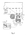
- fig. 1 shows that due to the configuration of the agricultural machine 1 at least two blind areas 4, 5 result for the driver 7.
- the cameras 8, 9 are being provided at the front end of the front attachment unit 2, which cameras 8, 9 are being directed to the respective sides of the agricultural machine 1 in opposite directions.
- the blind areas 4, 5 are effectively eliminated.
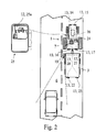
- Fig. 2 shows a different configuration of the agricultural machine 1, which configuration leads to another blind area 6. This blind area 6 is being eliminated with the camera 10, which camera 10 is directed rearwards.
- the two configurations of the driver vision support system shown in fig. 1 and 2 may be realized by only two cameras 8, 9.
- the camera 10 shown in fig. 2 may be, for example, the camera 8 shown in fig. 1 .
- a large number of configuration changes of the driver vision support system are possible with only a low number of cameras 8-10.
- a camera interface arrangement 13 is provided which allows the attachment and detachment of the at least one camera 8-10 and/or the variation of the viewing direction of the at least one camera 8-10 during normal use.
- the camera interface arrangement 13 preferably comprises magnetic fixing means for a detachably attachment of the at least one camera 8-10 to the agricultural machine 1 or the attachment unit 2.
- the magnetic fixing means are cost-effective and robust against rough working conditions including dusty and/or dirty environments.
- the camera interface arrangement 13 also includes a data interface which allows the camera signal to be transferred to the respective output device 11, 12.
- the data interface can be wire bound. Alternatively the data interface is wireless.
- the camera interface arrangement 13 includes an electrical power interface for the voltage supply of the camera 8-10, However, it is possible that this can be omitted if the at least one camera 8-10 is battery powered.
- the camera interface arrangement 13 includes a number of camera receptions 14 to 23 which are all designed for detachably receiving a camera 8-10.
- the camera receptions 14-23 are fixed to the agricultural machine 1 as well as to the attachment unit 2 which is attached to the agricultural machine 1 in fig. 1 .
- the camera receptions 14-23 preferably each comprise a reception body that may undetachably be fixed to the agricultural machine 1 or to the attachment unit 2 attached to the agricultural machine 1.
- the camera receptions 14-23 are fixed to the respective component by an adhesive, by screws or the like.
- the camera receptions 14-23 here and preferably are each provided with magnetic fixing means as noted above for a detachably reception of the at least one camera 8-10.
- the camera receptions 14-23 not only provide a mechanical interface to the cameras 8-10, but may also provide the data interface and/or the power interface to the cameras 8-10. Accordingly, when a camera 8-10 is being attached to a camera reception 14-23 not only a mechanical connection, but also a data connection and/or a power connection is being established.
- the output device 11, 12 is a visual output device. In certain applications, however, it may be advantageous to have an output device 11, 12 which is an acoustic output device in addition or alternatively.
- the output devices 11, 12 are display screens.
- the display screen is a part of a stand-alone display device.
- the display device 24a is part of a control terminal 24, which in a certain control mode shows the respective camera signals.
- a display screen 25a is integrated into an inside or outside rearview mirror 25.
- the integration of the display device 25a into an outside rearview mirror 25 is shown in fig. 2 in addition to the display screen 24a of the control terminal 24.
- a camera control 26 which receives the camera signals and which controls the output of the camera signals to the output devices 11, 12.
- the driver manually defines which camera signals are to be displayed in which output device 11, 12, For this a manual input device may be provided.
- the camera control 26 automatically distribute camera signals to the optimal output device 11, 12.
- the camera control 26 has to be able to detect the location of the respective cameras 8-10.
- the camera receptions 14-23 may be helpful.
- the camera control 26 may detect the location of a camera 8-10 by detecting in which camera reception 14-23 the camera 8-10 is actually being received.
- the camera control 26 may be connected to all data interfaces of all camera receptions 14-23, allowing to communicate with all cameras 8-10 once the cameras 8-10 are being received by the respective camera reception 14-23.
- a simple data handshake may be performed when the respective camera 8-10 is being attached into a respective camera reception 14-23. After this handshake the camera control 26 has detected which camera 8-10 is being received in which camera reception 14-23.
- the camera control 26 outputs the camera signals of a camera 8-10 depending on the location of the camera 8-10, which location is detected by the camera control 26 as noted above.
- the camera control 26 distributes camera signals to different devices 11, 12 depending on the detected location of the respective camera 8-10. This distribution of camera signals to different output devices 11, 12 is performed based on a predetermined distribution strategy stored in a memory of the camera control 26.
- the camera signals of cameras 8 and 9 are being displayed in the display screen 24a which is part of the control terminal 24.
- the camera signals of camera 10, which is displayed in fig. 2 is being displayed in the display screen 25a of the outside rearview mirror 25.
- This distribution of the camera signals to the different output devices 11, 12 increases the user friendliness of the driver vision support system.
- One aspect shown in fig. 1 which is of independent importance is the fact that a single display screen 24a is used for displaying the camera signals of more than one camera 8-10, here of the two cameras 8, 9. This may be done in a split-screen-technique as shown by displaying the camera signals, here the respective camera pictures, side by side. Alternatively it is possible to display the camera signals of the more than one camera 8, 9 on the one display screen 24a sequentially.
- the camera control 26 also performs image processing of the camera signals, in order to detect whether a predetermined class of objects is captured by a respective camera 8-10.
- the object shown in the left part of the display device 24a of the control terminal 24 in fig. 1 may be detected as an approaching car based on image processing.
- This information may be output by another output device which may well be an acoustic output device as noted above.
- a self propelled agricultural machine 1 with an above noted driver vision support system is claimed as such. It may be referred to all above noted explanations that have been given with respect to the proposed driver vision support system.
Abstract
Description
- The invention is directed to a driver vision support system for a self propelled agricultural machine according to
claim 1 and to a self propelled agricultural machine with such a driver vision support system according to claim 15. - The expression "self propelled agricultural machine" is to be understood in a broad sense. It not only includes all kinds of tractors for farming, but also telehandlers or combines.
- Today's self propelled agricultural machines normally may be used in a large quantity of applications. In order to adapt the agricultural machine to the respective task, the configuration of the agricultural machine may be varied by changing the mechanical set up of the agricultural machine. The variation of the mechanical set up may be performed for example by moving parts of the agricultural machine from a retracted to an extracted position. Another possibility for the variation of the configuration of the agricultural machine is to provide the agricultural machine with different attachment units like a front attachment unit or a rear attachment unit. Such attachment units may be mowers, swathers, plows or the like. The attachment units may be designed as rolling units or as units that are carried by the agricultural machine. Accordingly, an attachment unit in the present sense may be trailers such as forage wagons as well.
- One drawback of the known agricultural machines is the fact that in many cases there remain different blind areas which are outside of the visual reach of the user. This means, that the user is not able to visualize obstacles are located in those blind areas. This is especially true for the front area of a tractor which is provided with a long front section including the front axle and the engine hood, while the driver's cab is located in the rear of the tractor.
- The situation is even worse if the agricultural machine is provided with different front attachment units or rear attachment units as shown in
DE 20 2011 107 270 U1 - It is an object of the invention to provide a driver vision support system for a self propelled agricultural machine which improves the vision of the driver regarding the surrounding of the self propelled agricultural machine taking into account the possible variations in configuration of the agricultural machine.
- The above noted problem is solved by a driver vision support system according to
claim 1. - The basic idea underlying the invention is to provide a certain adaptability of the driver vision support system to the variable configuration of the agricultural machine.
- In detail the driver vision support system comprises at least one camera and at least one output device for the output of camera signals to the driver. The expression "camera signal" is to be understood in a broad sense including not only raw sensor signals but also electronically already processed signals that would be understood as "information"' in the terminology of information technology. Accordingly, the expression "camera signals" also includes camera picture information that may be displayed with an output device.
- The configuration of the driver vision support system is adaptable to the configuration of the agricultural machine by varying the location and/or the viewing di-reaction of the at least one camera during normal use such that the driver receives camera signals via the output device of at least one camera which is directed to at least one blind area.
- With the adaptability of the configuration of the driver vision support system to the configuration of the agricultural machine it is possible to eliminate as many blind areas as possible with the cameras available. The expression "eliminate" means that blind areas that go back on the respective configuration of the agricultural machine may be monitored by the respective cameras directed to those blind areas such that the user may detect obstacles or the like in those areas.
- Due to the variability of the configuration of the driver vision support system it is possible to achieve a considerable elimination of blind areas with a low numbers of cameras needed.
- An important aspect for the proposed solution is the concept of camera installation. According to the preferred embodiment of claim 6 a camera interface arrangement includes at least one camera reception for receiving a camera, which camera reception may be fixed to the agricultural machine or an attachment unit attached to the agricultural machine.
- With this preferred embodiment various camera receptions are fixed at various locations at the agricultural machine and/or at an attachment unit attached to the agricultural machine, such that the existing cameras may be attached to those receptions as needed in view of the blind areas which go back on the configuration of the agricultural machine.
- A rather user friendly embodiment is subject of claim 13. Here a camera control is provided that distributes camera signals to different output devices depending on the detected location of the respective camera. If, for example, a camera is directed to the rear section of the agricultural machine the camera control may output the camera signals to a display screen that is integrated into a rear view mirror. The camera signals of a camera which is directed to the side of the tractor, however, may be output by the camera control via a display device which is part of a control terminal inside the driver cab.
- A second teaching according to claim 15 is directed to a self propelled agricultural machine, especially a tractor with a driver vision support system as proposed above. All explanations given to the proposed driver vision support system awfully applicable to the proposed self propelled agricultural machine according to this second teaching.
- In the following the invention is being explained referring to the drawing. In the drawing show
- Fig. 1
- a proposed driver vision support system in its mounted state in a first configuration, and
- Fig. 2
- the driver vision support system according to
fig. 1 in a second configuration. - The proposed driver vision support system is designed for a self propelled
agricultural machine 1, which in the preferred embodiment shown in the drawing is atractor 1. Some of the possible alternatives for the self propelledagricultural machine 1 have been specified in the general part of the specification. - The
agricultural machine 1 has a configuration, which configuration may be varied by changing the mechanical set up of theagricultural machine 1. Infig. 1 the agricultural machine I is provided with afront attachment unit 2 which may be a mower or the like. Infig. 2 theagricultural machine 1 is provided with aforage wagon 3 which is being pulled by theagricultural machine 1. As a matter of completeness it may be pointed out that all kinds of configurations of theagricultural machine 1 are possible. For example the agricultural machine may be provided with a rear attachment unit which may be a plow or the like. - It may be taken from
fig. 1 andfig. 2 that depending on the configuration of theagricultural machine 1 different blind areas 4-6 may result which are outside the visual reach of thedriver 7. - In order to eliminate such blind areas in the above noted sense the driver vision support system comprises at least one camera 8-10 and at least one output device 11, 12 for the output of camera signals to the
driver 7. - The configuration of the driver vision support system is adaptable to the configuration of the
agricultural machine 1 by varying the location of the at least one camera 8-10 during normal use such that thedriver 7 receives camera signals via the output device 11, 12 of at least one camera 8-10 which is directed to at least one blind area 4-6. - In the embodiment shown in the drawing the variation of the configuration of the driver vision support system is performed by varying the location of the cameras 8-10. In addition or as an alternative it may be provided that the viewing direction of the at least one
camera 8-.10 may be varied during normal use. - In detail
fig. 1 shows that due to the configuration of theagricultural machine 1 at least twoblind areas 4, 5 result for thedriver 7. In order to eliminate thoseblind areas 4, 5 thecameras 8, 9 are being provided at the front end of thefront attachment unit 2, whichcameras 8, 9 are being directed to the respective sides of theagricultural machine 1 in opposite directions. With this configuration of the drive vision support system theblind areas 4, 5 are effectively eliminated. -
Fig. 2 shows a different configuration of theagricultural machine 1, which configuration leads to another blind area 6. This blind area 6 is being eliminated with the camera 10, which camera 10 is directed rearwards. - It may be pointed out that the two configurations of the driver vision support system shown in
fig. 1 and2 may be realized by only twocameras 8, 9. The camera 10 shown infig. 2 may be, for example, thecamera 8 shown infig. 1 . Here it becomes clear that a large number of configuration changes of the driver vision support system are possible with only a low number of cameras 8-10. - In order to realize the variable configuration of the driver vision support system a camera interface arrangement 13 is provided which allows the attachment and detachment of the at least one camera 8-10 and/or the variation of the viewing direction of the at least one camera 8-10 during normal use.
- The camera interface arrangement 13 preferably comprises magnetic fixing means for a detachably attachment of the at least one camera 8-10 to the
agricultural machine 1 or theattachment unit 2. The magnetic fixing means are cost-effective and robust against rough working conditions including dusty and/or dirty environments. - The camera interface arrangement 13 also includes a data interface which allows the camera signal to be transferred to the respective output device 11, 12. The data interface can be wire bound. Alternatively the data interface is wireless.
- In most cases it is necessary that the camera interface arrangement 13 includes an electrical power interface for the voltage supply of the camera 8-10, However, it is possible that this can be omitted if the at least one camera 8-10 is battery powered.
- In the preferred embodiment shown the camera interface arrangement 13 includes a number of camera receptions 14 to 23 which are all designed for detachably receiving a camera 8-10. The camera receptions 14-23 are fixed to the
agricultural machine 1 as well as to theattachment unit 2 which is attached to theagricultural machine 1 infig. 1 . - The camera receptions 14-23 preferably each comprise a reception body that may undetachably be fixed to the
agricultural machine 1 or to theattachment unit 2 attached to theagricultural machine 1. Preferably the camera receptions 14-23 are fixed to the respective component by an adhesive, by screws or the like. - The camera receptions 14-23 here and preferably are each provided with magnetic fixing means as noted above for a detachably reception of the at least one camera 8-10.
- Preferably the camera receptions 14-23 not only provide a mechanical interface to the cameras 8-10, but may also provide the data interface and/or the power interface to the cameras 8-10. Accordingly, when a camera 8-10 is being attached to a camera reception 14-23 not only a mechanical connection, but also a data connection and/or a power connection is being established.
- There are a number of possibilities for the realization of the output device 11, 12. In a preferred embodiment the output device 11, 12 is a visual output device. In certain applications, however, it may be advantageous to have an output device 11, 12 which is an acoustic output device in addition or alternatively.
- In the drawing the output devices 11, 12 are display screens. In an easy to realize embodiment the display screen is a part of a stand-alone display device. In the embodiment shown in
fig. 1 the display device 24a is part of acontrol terminal 24, which in a certain control mode shows the respective camera signals. Alternatively it may be provided that a display screen 25a is integrated into an inside or outsiderearview mirror 25. The integration of the display device 25a into an outsiderearview mirror 25 is shown infig. 2 in addition to the display screen 24a of thecontrol terminal 24. - Especially in the case that more than one output device 11, 12 is provided it may be advantageous to also provide a
camera control 26 which receives the camera signals and which controls the output of the camera signals to the output devices 11, 12. In the easiest case the driver manually defines which camera signals are to be displayed in which output device 11, 12, For this a manual input device may be provided. - However, in order to increase the user friendliness it may be preferable to have the
camera control 26 automatically distribute camera signals to the optimal output device 11, 12. For this thecamera control 26 has to be able to detect the location of the respective cameras 8-10. For this the camera receptions 14-23 may be helpful. - Preferably, the
camera control 26 may detect the location of a camera 8-10 by detecting in which camera reception 14-23 the camera 8-10 is actually being received. For this thecamera control 26 may be connected to all data interfaces of all camera receptions 14-23, allowing to communicate with all cameras 8-10 once the cameras 8-10 are being received by the respective camera reception 14-23. For example, a simple data handshake may be performed when the respective camera 8-10 is being attached into a respective camera reception 14-23. After this handshake thecamera control 26 has detected which camera 8-10 is being received in which camera reception 14-23. - In an especially advantageous embodiment the
camera control 26 outputs the camera signals of a camera 8-10 depending on the location of the camera 8-10, which location is detected by thecamera control 26 as noted above. - Further preferably the
camera control 26 distributes camera signals to different devices 11, 12 depending on the detected location of the respective camera 8-10. This distribution of camera signals to different output devices 11, 12 is performed based on a predetermined distribution strategy stored in a memory of thecamera control 26. - For example, as shown in
fig. 1 , the camera signals ofcameras 8 and 9 are being displayed in the display screen 24a which is part of thecontrol terminal 24. The camera signals of camera 10, which is displayed infig. 2 , however, is being displayed in the display screen 25a of the outsiderearview mirror 25. This distribution of the camera signals to the different output devices 11, 12 increases the user friendliness of the driver vision support system. - One aspect shown in
fig. 1 which is of independent importance is the fact that a single display screen 24a is used for displaying the camera signals of more than one camera 8-10, here of the twocameras 8, 9. This may be done in a split-screen-technique as shown by displaying the camera signals, here the respective camera pictures, side by side. Alternatively it is possible to display the camera signals of the more than onecamera 8, 9 on the one display screen 24a sequentially. - It may be especially advantageous that the
camera control 26 also performs image processing of the camera signals, in order to detect whether a predetermined class of objects is captured by a respective camera 8-10. For example, the object shown in the left part of the display device 24a of thecontrol terminal 24 infig. 1 may be detected as an approaching car based on image processing. This information may be output by another output device which may well be an acoustic output device as noted above. - According to another teaching a self propelled
agricultural machine 1 with an above noted driver vision support system is claimed as such. It may be referred to all above noted explanations that have been given with respect to the proposed driver vision support system.
Claims (15)
- Driver vision support system for a self propelled agricultural machine (1), wherein the agricultural machine (1) has a configuration, which configuration may be varied by changing the mechanical setup of the agricultural machine (1), wherein depending on the configuration of the agricultural machine (1) different blind areas (4-6) result which are outside the visual reach of the driver (7), wherein the driver vision support system comprises at least one camera (8-10) and at least one output device (11,12) for the output of camera signals to the driver (7), wherein the configuration of the driver vision support system is adaptable to the configuration of the agricultural machine (1) by varying the location and/or the viewing direction of the at least one camera (8-10) during normal use such that the driver (7) receives camera signals via the output device (11,12) of at least one camera (8-10) which is directed to at least one blind area (4-6).
- Driver vision support system according to claim 1, characterized in that a camera interface arrangement (13) is provided which allows the attachment and detachment of the at least one camera (8-10) and/or the variation of the viewing direction of the at least one camera (8-10) during normal use.
- Driver vision support system according to claim 1 or 2, characterized in that the camera interface arrangement (13) comprises magnetic fixing means for a detachably attachment of the at least one camera (8-10).
- Driver vision support system according to one of the preceding claims, characterized in that the camera interface arrangement (13) includes a data interface, wherein the data interface is wire bound, or, wherein the data interface is wireless.
- Driver vision support system according to one of the preceding claims, characterized in that the camera interface arrangement (13) includes an electrical power interface.
- Driver vision support system according to one of the preceding claims, characterized in that the camera interface arrangement (13) includes at least one camera reception (14-23) for receiving a camera (8-10), which camera reception (14-23) may be fixed to the agricultural machine (1) or an attachment unit (2) attached to the agricultural machine (1).
- Driver vision support system according to one of the preceding claims, characterized in that the camera reception (14-23) comprises a reception body that may be fixed to the agricultural machine (1) or an attachment unit (2) attached to the agricultural machine (1).
- Driver vision support system according to one of the preceding claims, characterized in that the camera reception (14-23) provides the data interface and/or the power interface to the camera (8-10).
- Driver vision support system according to one of the preceding claims, characterized in that an output device (14-23) is a visual output device, and/or, wherein an output device (11,12) is an acoustic output device.
- Driver vision support system according to one of the preceding claims, characterized in that an output device (11,12) is a display screen, preferably, wherein the display screen is part of a stand alone display device, or wherein the display screen (11,12) is part of a control terminal (24), or, wherein the display screen is integrated into a rearview mirror (25).
- Driver vision support system according to one of the preceding claims, characterized in that a camera control (26) is provided which receives the camera signals and which controls the output of the camera signals to the at least one output device (11,12).
- Driver vision support system according to claim 6 and, if so, to one of the claims 7 to 11, characterized in that at least two camera receptions (14-23) are provided for receiving a camera (8-10) and wherein the camera control (26) detects the location of a camera (8-10) by detecting in which camera reception (14-23) the camera (8-10) is actually being received.
- Driver vision support system according to one of the preceding claims, characterized in that the camera control (26) outputs the camera signals of a camera (8-10) depending on the location of the camera (8-10), preferably, wherein the camera control (26) distributes camera signals to different output devices (11,12) depending on the detected location of the respective camera (8-10).
- Driver vision support system according to one of the preceding claims, characterized in that the camera control (26) performs image processing of the camera signals and thereby detects whether a predetermined class of objects is captured by a respective camera (8-10).
- Self propelled agricultural machine with a driver vision support system according to one of the preceding claims, wherein the agricultural machine (1) has a configuration, which configuration may be varied by changing the mechanical setup of the agricultural machine (1), wherein depending on the configuration of the agricultural machine (1) different blind areas (4-6) result which are outside the visual reach of the driver (7), wherein the driver vision support system comprises at least one camera (8-10) and at least one output device (11,12) for the output of camera signals to the driver (7), wherein the configuration of the driver vision support system is adaptable to the configuration of the agricultural machine (1) by varying the location and/or the viewing direction of the at least one camera (8-10) during normal use such that the drive (7) receives camera signals via the output device (11,12) of at least one camera (8-10) which is directed to at least one blind area (4-6).
Priority Applications (2)
| Application Number | Priority Date | Filing Date | Title |
|---|---|---|---|
| EP12008321.7A EP2743132B1 (en) | 2012-12-13 | 2012-12-13 | Driver vision support system |
| RU2013154740A RU2636329C2 (en) | 2012-12-13 | 2013-12-11 | Driver's field of vision support system |
Applications Claiming Priority (1)
| Application Number | Priority Date | Filing Date | Title |
|---|---|---|---|
| EP12008321.7A EP2743132B1 (en) | 2012-12-13 | 2012-12-13 | Driver vision support system |
Publications (2)
| Publication Number | Publication Date |
|---|---|
| EP2743132A1 true EP2743132A1 (en) | 2014-06-18 |
| EP2743132B1 EP2743132B1 (en) | 2017-08-02 |
Family
ID=47602730
Family Applications (1)
| Application Number | Title | Priority Date | Filing Date |
|---|---|---|---|
| EP12008321.7A Active EP2743132B1 (en) | 2012-12-13 | 2012-12-13 | Driver vision support system |
Country Status (2)
| Country | Link |
|---|---|
| EP (1) | EP2743132B1 (en) |
| RU (1) | RU2636329C2 (en) |
Cited By (3)
| Publication number | Priority date | Publication date | Assignee | Title |
|---|---|---|---|---|
| WO2016055063A1 (en) * | 2014-10-10 | 2016-04-14 | Conti Temic Microelectronic Gmbh | Additional outside mirror system for a towing vehicle-trailer combination |
| ITUB20154924A1 (en) * | 2015-11-06 | 2017-05-06 | Same Deutz Fahr Italia S P A | TRACTOR WITH VISION SYSTEM |
| BE1024929B1 (en) * | 2017-05-09 | 2018-08-13 | Cnh Industrial Belgium Nv | IMPROVEMENTS IN OR RELATING TO VEHICLE / TRAILER COMBINATIONS |
Families Citing this family (2)
| Publication number | Priority date | Publication date | Assignee | Title |
|---|---|---|---|---|
| DE102022108899A1 (en) | 2022-04-12 | 2023-10-12 | Claas Selbstfahrende Erntemaschinen Gmbh | Mirror replacement system and agricultural work machine with mirror replacement system |
| DE102022108925A1 (en) | 2022-04-12 | 2023-10-12 | Claas Selbstfahrende Erntemaschinen Gmbh | Mirror replacement system and agricultural work machine with mirror replacement system |
Citations (5)
| Publication number | Priority date | Publication date | Assignee | Title |
|---|---|---|---|---|
| DE4339600A1 (en) * | 1993-11-20 | 1995-05-24 | Kloeckner Humboldt Deutz Ag | Agricultural or earthmoving vehicle with optical monitoring of working tool |
| US5956079A (en) * | 1997-03-03 | 1999-09-21 | Agriland Designs, Inc. | Agricultural vehicle monitoring system |
| DE202004013984U1 (en) * | 2004-09-08 | 2006-01-19 | Mekra Lang Gmbh & Co. Kg | camera system |
| US20110149077A1 (en) * | 2009-12-22 | 2011-06-23 | Marc Robert | Side Mirrow System With Video Display |
| DE202011107270U1 (en) | 2011-05-03 | 2012-02-01 | Claas Saulgau Gmbh | Harvesting machine with at least two cross conveyors |
Family Cites Families (5)
| Publication number | Priority date | Publication date | Assignee | Title |
|---|---|---|---|---|
| SU1426885A1 (en) * | 1987-01-26 | 1988-09-30 | Ростовский-На-Дону Институт Сельскохозяйственного Машиностроения | Vehicle cab |
| RU2096202C1 (en) * | 1996-08-26 | 1997-11-20 | Иван Петрович Калько | Vehicle periscope-type arrangement |
| RU2280973C1 (en) * | 2005-01-31 | 2006-08-10 | Иван Григорьевич Мухин | Mower |
| RU56414U1 (en) * | 2006-04-26 | 2006-09-10 | Борис Владимирович Гребенюк | SNOW CLEANER |
| RU79494U1 (en) * | 2008-08-06 | 2009-01-10 | Андрей Сергеевич Ванин | CAR-TRANSFORMER |
-
2012
- 2012-12-13 EP EP12008321.7A patent/EP2743132B1/en active Active
-
2013
- 2013-12-11 RU RU2013154740A patent/RU2636329C2/en active
Patent Citations (5)
| Publication number | Priority date | Publication date | Assignee | Title |
|---|---|---|---|---|
| DE4339600A1 (en) * | 1993-11-20 | 1995-05-24 | Kloeckner Humboldt Deutz Ag | Agricultural or earthmoving vehicle with optical monitoring of working tool |
| US5956079A (en) * | 1997-03-03 | 1999-09-21 | Agriland Designs, Inc. | Agricultural vehicle monitoring system |
| DE202004013984U1 (en) * | 2004-09-08 | 2006-01-19 | Mekra Lang Gmbh & Co. Kg | camera system |
| US20110149077A1 (en) * | 2009-12-22 | 2011-06-23 | Marc Robert | Side Mirrow System With Video Display |
| DE202011107270U1 (en) | 2011-05-03 | 2012-02-01 | Claas Saulgau Gmbh | Harvesting machine with at least two cross conveyors |
Cited By (10)
| Publication number | Priority date | Publication date | Assignee | Title |
|---|---|---|---|---|
| WO2016055063A1 (en) * | 2014-10-10 | 2016-04-14 | Conti Temic Microelectronic Gmbh | Additional outside mirror system for a towing vehicle-trailer combination |
| ITUB20154924A1 (en) * | 2015-11-06 | 2017-05-06 | Same Deutz Fahr Italia S P A | TRACTOR WITH VISION SYSTEM |
| EP3165406A1 (en) * | 2015-11-06 | 2017-05-10 | Same Deutz-Fahr Group SpA | Tractor with vision system |
| BE1024929B1 (en) * | 2017-05-09 | 2018-08-13 | Cnh Industrial Belgium Nv | IMPROVEMENTS IN OR RELATING TO VEHICLE / TRAILER COMBINATIONS |
| WO2018206683A1 (en) * | 2017-05-09 | 2018-11-15 | Cnh Industrial Belgium Nv | Improvements in or relating to vehicle-trailer combinations |
| CN110612021A (en) * | 2017-05-09 | 2019-12-24 | 凯斯纽荷兰(中国)管理有限公司 | Improvements in or relating to vehicle-trailer combinations |
| RU2738423C1 (en) * | 2017-05-09 | 2020-12-14 | СиЭнЭйч ИНДАСТРИАЛ БЕЛДЖИУМ НВ | Combination of movable vehicle and trailer and method of controlling combination of vehicle and trailer |
| AU2018265094B2 (en) * | 2017-05-09 | 2021-04-08 | Cnh Industrial Belgium Nv | Improvements in or relating to vehicle-trailer combinations |
| US11185004B2 (en) | 2017-05-09 | 2021-11-30 | Cnh Industrial America Llc | Vehicle-trailer combinations |
| EP3634103B1 (en) | 2017-05-09 | 2022-10-19 | CNH Industrial Belgium NV | Improvements in or relating to vehicle-trailer combinations |
Also Published As
| Publication number | Publication date |
|---|---|
| EP2743132B1 (en) | 2017-08-02 |
| RU2013154740A (en) | 2015-06-20 |
| RU2636329C2 (en) | 2017-11-22 |
Similar Documents
| Publication | Publication Date | Title |
|---|---|---|
| EP2743132B1 (en) | Driver vision support system | |
| US20190118717A1 (en) | Full mirror display utilizing a trailer camera | |
| US20130076007A1 (en) | Vehicle backup camera for viewing a mid-chassis mounted trailer hitching structure | |
| JP5929509B2 (en) | Vehicle inner mirror system and vehicle equipped with the vehicle inner mirror system | |
| CN203472677U (en) | Panoramic image system and vehicle | |
| JP3197668U (en) | Visual field auxiliary means for vehicles | |
| US11465560B2 (en) | Vehicular vision system that utilizes trailer camera | |
| JP6265186B2 (en) | Automatic driving device | |
| CN210139816U (en) | Vehicle vision blind area monitoring system and vehicle | |
| US20210053490A1 (en) | Video Monitoring System for a Motor Vehicle | |
| CN203888721U (en) | Integrated device for eliminating dead zones of column A and column B of automobile | |
| CN105371811B (en) | The system for measuring hitch angle | |
| US20160355134A1 (en) | Back-up Camera System for Towed Trailer | |
| WO2012062689A1 (en) | Method for displaying images on a display device, a camera system and motor vehicle having a camera system | |
| CN104608695A (en) | Vehicle-mounted electronic rearview mirror head-up displaying device | |
| US10737725B2 (en) | System and method for assisting parallel parking using orthogonal projection | |
| CN202294512U (en) | Commercial vehicle backing rearview device | |
| US20170083771A1 (en) | Vehicle mounted side camera system | |
| US20090002487A1 (en) | Portable Vehicle Mounted Monitoring System | |
| EP3143854B1 (en) | Agricultural working machine | |
| US20160046238A1 (en) | Side View Mirror Alignment System | |
| JP2000201347A5 (en) | ||
| US10596965B2 (en) | Third eye tractor trailer blind side driving system | |
| JP3202242U (en) | Confirmation device for safe driving and connected vehicle equipped with the same | |
| Smits | New Fields of Vision through Removable Wi-Fi Camera |
Legal Events
| Date | Code | Title | Description |
|---|---|---|---|
| PUAI | Public reference made under article 153(3) epc to a published international application that has entered the european phase |
Free format text: ORIGINAL CODE: 0009012 |
|
| 17P | Request for examination filed |
Effective date: 20121213 |
|
| AK | Designated contracting states |
Kind code of ref document: A1 Designated state(s): AL AT BE BG CH CY CZ DE DK EE ES FI FR GB GR HR HU IE IS IT LI LT LU LV MC MK MT NL NO PL PT RO RS SE SI SK SM TR |
|
| AX | Request for extension of the european patent |
Extension state: BA ME |
|
| R17P | Request for examination filed (corrected) |
Effective date: 20141218 |
|
| RBV | Designated contracting states (corrected) |
Designated state(s): AL AT BE BG CH CY CZ DE DK EE ES FI FR GB GR HR HU IE IS IT LI LT LU LV MC MK MT NL NO PL PT RO RS SE SI SK SM TR |
|
| 17Q | First examination report despatched |
Effective date: 20151127 |
|
| REG | Reference to a national code |
Ref country code: DE Ref legal event code: R079 Ref document number: 602012035205 Country of ref document: DE Free format text: PREVIOUS MAIN CLASS: B60R0001000000 Ipc: A01B0076000000 |
|
| GRAP | Despatch of communication of intention to grant a patent |
Free format text: ORIGINAL CODE: EPIDOSNIGR1 |
|
| RIC1 | Information provided on ipc code assigned before grant |
Ipc: B60R 1/12 20060101ALN20170209BHEP Ipc: A01B 76/00 20060101AFI20170209BHEP Ipc: H04N 101/00 20060101ALN20170209BHEP Ipc: B60R 1/00 20060101ALI20170209BHEP Ipc: H04N 5/225 20060101ALI20170209BHEP Ipc: A01B 69/00 20060101ALI20170209BHEP |
|
| INTG | Intention to grant announced |
Effective date: 20170222 |
|
| GRAS | Grant fee paid |
Free format text: ORIGINAL CODE: EPIDOSNIGR3 |
|
| GRAA | (expected) grant |
Free format text: ORIGINAL CODE: 0009210 |
|
| AK | Designated contracting states |
Kind code of ref document: B1 Designated state(s): AL AT BE BG CH CY CZ DE DK EE ES FI FR GB GR HR HU IE IS IT LI LT LU LV MC MK MT NL NO PL PT RO RS SE SI SK SM TR |
|
| REG | Reference to a national code |
Ref country code: CH Ref legal event code: EP Ref country code: AT Ref legal event code: REF Ref document number: 913406 Country of ref document: AT Kind code of ref document: T Effective date: 20170815 |
|
| REG | Reference to a national code |
Ref country code: IE Ref legal event code: FG4D |
|
| REG | Reference to a national code |
Ref country code: DE Ref legal event code: R096 Ref document number: 602012035205 Country of ref document: DE |
|
| REG | Reference to a national code |
Ref country code: NL Ref legal event code: MP Effective date: 20170802 |
|
| REG | Reference to a national code |
Ref country code: AT Ref legal event code: MK05 Ref document number: 913406 Country of ref document: AT Kind code of ref document: T Effective date: 20170802 |
|
| REG | Reference to a national code |
Ref country code: FR Ref legal event code: PLFP Year of fee payment: 6 |
|
| REG | Reference to a national code |
Ref country code: LT Ref legal event code: MG4D |
|
| PG25 | Lapsed in a contracting state [announced via postgrant information from national office to epo] |
Ref country code: NO Free format text: LAPSE BECAUSE OF FAILURE TO SUBMIT A TRANSLATION OF THE DESCRIPTION OR TO PAY THE FEE WITHIN THE PRESCRIBED TIME-LIMIT Effective date: 20171102 Ref country code: AT Free format text: LAPSE BECAUSE OF FAILURE TO SUBMIT A TRANSLATION OF THE DESCRIPTION OR TO PAY THE FEE WITHIN THE PRESCRIBED TIME-LIMIT Effective date: 20170802 Ref country code: LT Free format text: LAPSE BECAUSE OF FAILURE TO SUBMIT A TRANSLATION OF THE DESCRIPTION OR TO PAY THE FEE WITHIN THE PRESCRIBED TIME-LIMIT Effective date: 20170802 Ref country code: FI Free format text: LAPSE BECAUSE OF FAILURE TO SUBMIT A TRANSLATION OF THE DESCRIPTION OR TO PAY THE FEE WITHIN THE PRESCRIBED TIME-LIMIT Effective date: 20170802 Ref country code: HR Free format text: LAPSE BECAUSE OF FAILURE TO SUBMIT A TRANSLATION OF THE DESCRIPTION OR TO PAY THE FEE WITHIN THE PRESCRIBED TIME-LIMIT Effective date: 20170802 Ref country code: SE Free format text: LAPSE BECAUSE OF FAILURE TO SUBMIT A TRANSLATION OF THE DESCRIPTION OR TO PAY THE FEE WITHIN THE PRESCRIBED TIME-LIMIT Effective date: 20170802 Ref country code: NL Free format text: LAPSE BECAUSE OF FAILURE TO SUBMIT A TRANSLATION OF THE DESCRIPTION OR TO PAY THE FEE WITHIN THE PRESCRIBED TIME-LIMIT Effective date: 20170802 |
|
| PG25 | Lapsed in a contracting state [announced via postgrant information from national office to epo] |
Ref country code: ES Free format text: LAPSE BECAUSE OF FAILURE TO SUBMIT A TRANSLATION OF THE DESCRIPTION OR TO PAY THE FEE WITHIN THE PRESCRIBED TIME-LIMIT Effective date: 20170802 Ref country code: GR Free format text: LAPSE BECAUSE OF FAILURE TO SUBMIT A TRANSLATION OF THE DESCRIPTION OR TO PAY THE FEE WITHIN THE PRESCRIBED TIME-LIMIT Effective date: 20171103 Ref country code: BG Free format text: LAPSE BECAUSE OF FAILURE TO SUBMIT A TRANSLATION OF THE DESCRIPTION OR TO PAY THE FEE WITHIN THE PRESCRIBED TIME-LIMIT Effective date: 20171102 Ref country code: RS Free format text: LAPSE BECAUSE OF FAILURE TO SUBMIT A TRANSLATION OF THE DESCRIPTION OR TO PAY THE FEE WITHIN THE PRESCRIBED TIME-LIMIT Effective date: 20170802 Ref country code: PL Free format text: LAPSE BECAUSE OF FAILURE TO SUBMIT A TRANSLATION OF THE DESCRIPTION OR TO PAY THE FEE WITHIN THE PRESCRIBED TIME-LIMIT Effective date: 20170802 Ref country code: IS Free format text: LAPSE BECAUSE OF FAILURE TO SUBMIT A TRANSLATION OF THE DESCRIPTION OR TO PAY THE FEE WITHIN THE PRESCRIBED TIME-LIMIT Effective date: 20171202 Ref country code: LV Free format text: LAPSE BECAUSE OF FAILURE TO SUBMIT A TRANSLATION OF THE DESCRIPTION OR TO PAY THE FEE WITHIN THE PRESCRIBED TIME-LIMIT Effective date: 20170802 |
|
| PG25 | Lapsed in a contracting state [announced via postgrant information from national office to epo] |
Ref country code: RO Free format text: LAPSE BECAUSE OF FAILURE TO SUBMIT A TRANSLATION OF THE DESCRIPTION OR TO PAY THE FEE WITHIN THE PRESCRIBED TIME-LIMIT Effective date: 20170802 Ref country code: DK Free format text: LAPSE BECAUSE OF FAILURE TO SUBMIT A TRANSLATION OF THE DESCRIPTION OR TO PAY THE FEE WITHIN THE PRESCRIBED TIME-LIMIT Effective date: 20170802 Ref country code: CZ Free format text: LAPSE BECAUSE OF FAILURE TO SUBMIT A TRANSLATION OF THE DESCRIPTION OR TO PAY THE FEE WITHIN THE PRESCRIBED TIME-LIMIT Effective date: 20170802 |
|
| REG | Reference to a national code |
Ref country code: DE Ref legal event code: R097 Ref document number: 602012035205 Country of ref document: DE |
|
| PG25 | Lapsed in a contracting state [announced via postgrant information from national office to epo] |
Ref country code: SM Free format text: LAPSE BECAUSE OF FAILURE TO SUBMIT A TRANSLATION OF THE DESCRIPTION OR TO PAY THE FEE WITHIN THE PRESCRIBED TIME-LIMIT Effective date: 20170802 Ref country code: EE Free format text: LAPSE BECAUSE OF FAILURE TO SUBMIT A TRANSLATION OF THE DESCRIPTION OR TO PAY THE FEE WITHIN THE PRESCRIBED TIME-LIMIT Effective date: 20170802 Ref country code: SK Free format text: LAPSE BECAUSE OF FAILURE TO SUBMIT A TRANSLATION OF THE DESCRIPTION OR TO PAY THE FEE WITHIN THE PRESCRIBED TIME-LIMIT Effective date: 20170802 Ref country code: IT Free format text: LAPSE BECAUSE OF FAILURE TO SUBMIT A TRANSLATION OF THE DESCRIPTION OR TO PAY THE FEE WITHIN THE PRESCRIBED TIME-LIMIT Effective date: 20170802 |
|
| PLBE | No opposition filed within time limit |
Free format text: ORIGINAL CODE: 0009261 |
|
| STAA | Information on the status of an ep patent application or granted ep patent |
Free format text: STATUS: NO OPPOSITION FILED WITHIN TIME LIMIT |
|
| 26N | No opposition filed |
Effective date: 20180503 |
|
| REG | Reference to a national code |
Ref country code: CH Ref legal event code: PL |
|
| GBPC | Gb: european patent ceased through non-payment of renewal fee |
Effective date: 20171213 |
|
| PG25 | Lapsed in a contracting state [announced via postgrant information from national office to epo] |
Ref country code: SI Free format text: LAPSE BECAUSE OF FAILURE TO SUBMIT A TRANSLATION OF THE DESCRIPTION OR TO PAY THE FEE WITHIN THE PRESCRIBED TIME-LIMIT Effective date: 20170802 |
|
| REG | Reference to a national code |
Ref country code: IE Ref legal event code: MM4A |
|
| PG25 | Lapsed in a contracting state [announced via postgrant information from national office to epo] |
Ref country code: MT Free format text: LAPSE BECAUSE OF NON-PAYMENT OF DUE FEES Effective date: 20171213 Ref country code: LU Free format text: LAPSE BECAUSE OF NON-PAYMENT OF DUE FEES Effective date: 20171213 |
|
| REG | Reference to a national code |
Ref country code: BE Ref legal event code: MM Effective date: 20171231 |
|
| PG25 | Lapsed in a contracting state [announced via postgrant information from national office to epo] |
Ref country code: IE Free format text: LAPSE BECAUSE OF NON-PAYMENT OF DUE FEES Effective date: 20171213 |
|
| PG25 | Lapsed in a contracting state [announced via postgrant information from national office to epo] |
Ref country code: CH Free format text: LAPSE BECAUSE OF NON-PAYMENT OF DUE FEES Effective date: 20171231 Ref country code: LI Free format text: LAPSE BECAUSE OF NON-PAYMENT OF DUE FEES Effective date: 20171231 Ref country code: BE Free format text: LAPSE BECAUSE OF NON-PAYMENT OF DUE FEES Effective date: 20171231 Ref country code: GB Free format text: LAPSE BECAUSE OF NON-PAYMENT OF DUE FEES Effective date: 20171213 |
|
| PG25 | Lapsed in a contracting state [announced via postgrant information from national office to epo] |
Ref country code: MC Free format text: LAPSE BECAUSE OF FAILURE TO SUBMIT A TRANSLATION OF THE DESCRIPTION OR TO PAY THE FEE WITHIN THE PRESCRIBED TIME-LIMIT Effective date: 20170802 Ref country code: HU Free format text: LAPSE BECAUSE OF FAILURE TO SUBMIT A TRANSLATION OF THE DESCRIPTION OR TO PAY THE FEE WITHIN THE PRESCRIBED TIME-LIMIT; INVALID AB INITIO Effective date: 20121213 |
|
| PG25 | Lapsed in a contracting state [announced via postgrant information from national office to epo] |
Ref country code: CY Free format text: LAPSE BECAUSE OF NON-PAYMENT OF DUE FEES Effective date: 20170802 |
|
| PG25 | Lapsed in a contracting state [announced via postgrant information from national office to epo] |
Ref country code: MK Free format text: LAPSE BECAUSE OF FAILURE TO SUBMIT A TRANSLATION OF THE DESCRIPTION OR TO PAY THE FEE WITHIN THE PRESCRIBED TIME-LIMIT Effective date: 20170802 |
|
| PG25 | Lapsed in a contracting state [announced via postgrant information from national office to epo] |
Ref country code: TR Free format text: LAPSE BECAUSE OF FAILURE TO SUBMIT A TRANSLATION OF THE DESCRIPTION OR TO PAY THE FEE WITHIN THE PRESCRIBED TIME-LIMIT Effective date: 20170802 |
|
| PG25 | Lapsed in a contracting state [announced via postgrant information from national office to epo] |
Ref country code: PT Free format text: LAPSE BECAUSE OF FAILURE TO SUBMIT A TRANSLATION OF THE DESCRIPTION OR TO PAY THE FEE WITHIN THE PRESCRIBED TIME-LIMIT Effective date: 20170802 |
|
| PG25 | Lapsed in a contracting state [announced via postgrant information from national office to epo] |
Ref country code: AL Free format text: LAPSE BECAUSE OF FAILURE TO SUBMIT A TRANSLATION OF THE DESCRIPTION OR TO PAY THE FEE WITHIN THE PRESCRIBED TIME-LIMIT Effective date: 20170802 |
|
| P01 | Opt-out of the competence of the unified patent court (upc) registered |
Effective date: 20230515 |
|
| PGFP | Annual fee paid to national office [announced via postgrant information from national office to epo] |
Ref country code: FR Payment date: 20231221 Year of fee payment: 12 Ref country code: DE Payment date: 20231214 Year of fee payment: 12 |