EP2743631A2 - Rifle telescope mounting with adjustable predefined inclination - Google Patents
Rifle telescope mounting with adjustable predefined inclination Download PDFInfo
- Publication number
- EP2743631A2 EP2743631A2 EP13005372.1A EP13005372A EP2743631A2 EP 2743631 A2 EP2743631 A2 EP 2743631A2 EP 13005372 A EP13005372 A EP 13005372A EP 2743631 A2 EP2743631 A2 EP 2743631A2
- Authority
- EP
- European Patent Office
- Prior art keywords
- scope mount
- attachment
- front inclination
- adjustable front
- base body
- Prior art date
- Legal status (The legal status is an assumption and is not a legal conclusion. Google has not performed a legal analysis and makes no representation as to the accuracy of the status listed.)
- Granted
Links
- 239000000463 material Substances 0.000 claims description 5
- 230000002093 peripheral effect Effects 0.000 abstract 1
- 125000006850 spacer group Chemical group 0.000 description 7
- 238000010304 firing Methods 0.000 description 5
- 238000006073 displacement reaction Methods 0.000 description 4
- 230000006835 compression Effects 0.000 description 3
- 238000007906 compression Methods 0.000 description 3
- RNAMYOYQYRYFQY-UHFFFAOYSA-N 2-(4,4-difluoropiperidin-1-yl)-6-methoxy-n-(1-propan-2-ylpiperidin-4-yl)-7-(3-pyrrolidin-1-ylpropoxy)quinazolin-4-amine Chemical compound N1=C(N2CCC(F)(F)CC2)N=C2C=C(OCCCN3CCCC3)C(OC)=CC2=C1NC1CCN(C(C)C)CC1 RNAMYOYQYRYFQY-UHFFFAOYSA-N 0.000 description 2
- 238000009434 installation Methods 0.000 description 2
- 239000011295 pitch Substances 0.000 description 2
- 108090000623 proteins and genes Proteins 0.000 description 2
- 230000000712 assembly Effects 0.000 description 1
- 238000000429 assembly Methods 0.000 description 1
- 150000001875 compounds Chemical class 0.000 description 1
- 238000010276 construction Methods 0.000 description 1
- 230000003247 decreasing effect Effects 0.000 description 1
- 239000004922 lacquer Substances 0.000 description 1
- 238000004519 manufacturing process Methods 0.000 description 1
- 238000000034 method Methods 0.000 description 1
- 230000003287 optical effect Effects 0.000 description 1
- 230000003068 static effect Effects 0.000 description 1
- 230000003746 surface roughness Effects 0.000 description 1
Images


Classifications
-
- F—MECHANICAL ENGINEERING; LIGHTING; HEATING; WEAPONS; BLASTING
- F41—WEAPONS
- F41G—WEAPON SIGHTS; AIMING
- F41G1/00—Sighting devices
- F41G1/38—Telescopic sights specially adapted for smallarms or ordnance; Supports or mountings therefor
- F41G1/387—Mounting telescopic sights on smallarms
-
- F—MECHANICAL ENGINEERING; LIGHTING; HEATING; WEAPONS; BLASTING
- F41—WEAPONS
- F41G—WEAPON SIGHTS; AIMING
- F41G11/00—Details of sighting or aiming apparatus; Accessories
- F41G11/001—Means for mounting tubular or beam shaped sighting or aiming devices on firearms
- F41G11/003—Mountings with a dove tail element, e.g. "Picatinny rail systems"
-
- F—MECHANICAL ENGINEERING; LIGHTING; HEATING; WEAPONS; BLASTING
- F41—WEAPONS
- F41G—WEAPON SIGHTS; AIMING
- F41G11/00—Details of sighting or aiming apparatus; Accessories
- F41G11/001—Means for mounting tubular or beam shaped sighting or aiming devices on firearms
- F41G11/005—Mountings using a pivot point and an anchoring point
- F41G11/007—Mountings using a pivot point and an anchoring point the device being tilted in a vertical plane
Definitions
- the invention relates to a scope mount with adjustable pre-tilt to change the pre-tilt angle between scope and barrel when shooting at long distances so that the vertical displacement of the scope is sufficient to adjust it to the desired shooting distance can.
- the projectile After firing from a firearm, the projectile follows a trajectory, the curvature of which depends on various influencing factors, such as projectile weight and projectile velocity.
- the telescopic sight can be adjusted to different shooting distances by adjusting the reticle.
- the adjustment path of each riflescope is mechanically limited, so that, for example, only a distance range of about 50 - 600 m can be covered. If the desired shooting distance is outside this range, for example at 800 m, this can no longer be achieved by adjusting the reticle.
- Riflescopes are connected to the firearm using riflescope mountings. Normally, the optical axis of the telescopic sight and the barrel axis of the weapon are coaxial with each other. Due to the greatly decreasing at long distances to the target trajectory of the projectile in such cases, the riflescope is mounted with a vorgeneigten scope mount on the weapon. In this case, different pretilt angles are necessary for different combinations of ammunition, barrel, weapon system, scope mount, telescopic sight and desired shot distance, so that the available vertical displacement of the scope is sufficient to set the reticle to different firing ranges.
- the riflescope is mounted with a riflescope assembly which has a fixed pretilt of, for example, 20 MOA ( M inute O f A ngle, angular minutes), this combination may suit a particular application. However, another combination may require a different pretilt angle be able to set the sight of the riflescope to the desired shooting distance can.
- a riflescope assembly which has a fixed pretilt of, for example, 20 MOA ( M inute O f A ngle, angular minutes)
- this combination may suit a particular application.
- another combination may require a different pretilt angle be able to set the sight of the riflescope to the desired shooting distance can.
- a rifle scope mount with adjustable forward tilt can be used in hunting or sport shooting.
- military-used weapons with a particularly long range and correspondingly powerful calibers such an assembly brings decisive advantages for the user.
- the shaft or the screw in at least one of the two parts must have a slight radial play.
- this game is very small in precisely worked hinge joints, but can lead to precision losses during use, when the forces are large enough and the shaft is radially displaced within the bore in the context of this game.
- the axial clamping together of the hinge by means of a screw is due to the necessary play the shaft in one of the components ultimately a frictional and no positive connection.
- Absolute reliability and ruggedness in the harshest of conditions is crucial, especially for military-grade weapons.
- the scope mount from as few as possible Parts exist and the connection of the individual components should be positive and not frictionally.
- as little as possible parts to be lost should be installed, which means that the scope mount for adjusting the tilt should not be disassembled or removed from the weapon if possible.
- Of particular importance is the simplest possible handling of the adjustment so that operator error can be largely excluded.
- the object of the invention is to overcome the described disadvantage of the prior art.
- a riflescope mounting with adjustable tilt which is characterized in that a base body and an attachment by the arrangement of a clamping screw at an angle greater than the self-locking material pairing and less than 90 ° have a positive connection.
- the object of the invention is further achieved by telescopic sight mounting with adjustable pre-tilt, which is characterized in that the base body and the attachment have a conical connection.
- the scope mount according to the invention meets the requirements mentioned in an excellent manner.
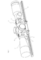
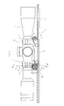
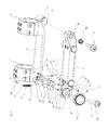
- Fig. 1 and 2 show a riflescope mounting 1, the main body 2 by way of example with a in the utility model DE 20 2009 017 398.4 explained clamping system is provided, wherein the base body is fixed by means of the clamping system on a Picatinny rail 4.
- the Picatinny rail is in turn mounted on the gun case (not shown in the figures).
- the attachment 3 clamps together with the front half-shell 5 and the rear half-shell 6, the riflescope 7.
- the top of the article 3 may be provided with a further Picatinny rail, on which the target device is mounted.
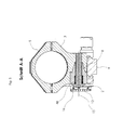
- the main body 2 has a taper 8 with a bore 9 (see Fig. 3 ).
- the attachment 3 has a countersink 10 (see Fig. 4 ) and an internal thread 11 (see Fig. 3 ) on.
- the first clamping screw 12 thus connects the main body 2 backlash with the attachment 3.
- the main body 2 forms with the attachment 3 a hinge about the hinge axis 13.
- a compound with a cylindrical hinge pin guaranteed absolute freedom of play in a conical connection, which is a great advantage.
- the main body 2 has an extension 14 and this in turn a circular pin 15 on which the thumbwheel 16 is rotatably mounted (see Fig. 6 ).
- a circular pin 15 on which the thumbwheel 16 is rotatably mounted (see Fig. 6 ).
- the threaded pin 17 is secured with locking lacquer in the internal thread 19 against rotation (see Fig. 8 ).
- the thumbwheel 16 has on its circumference, for example, eight flat surfaces with associated labels.
- the surface 20 is picked out by way of example, to which the lettering "20" is assigned. Each surface is assigned a certain angle of the pre-tilt.
- the necessary distance "A" in Fig. 8 the surfaces to the axis of rotation of the adjusting wheel 16 can be calculated via angle functions. In the exemplary embodiment shown, there are eight possible angular positions from 0 to 70 MOA in ten MOA increments. Other numbers of areas with different pitches are possible.
- the lateral surface of the adjusting wheel 16 may have a slope in the form of a spiral (not shown in the figures) to allow a continuous adjustment of the inclination angle. For tool-free handling the adjusting wheel 16 is provided with a corrugation 21.
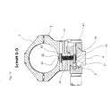
- a slot 22 extends through the circular pin 15 and the extension 14. This slot 22 has an angle ß to the contact surface 23 on the attachment 3 (see Fig. 4 and 9 ).
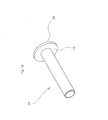
- the slot 22 is from a second clamping screw 24 (see Fig. 10 ), which rests in the clamped state with the base 25 of the head 26 on the surface 27 of the circular pin 15.
- the surface 27 is at right angles to the slot 22.
- the threaded shaft 28 of the second clamping screw 24 engages in the internal thread 29 in the attachment 3.
- the internal thread 29 has the same angle ß to the contact surface 23 as the slot 22 (see Fig. 4 . 7 and 9 ).
- the extension 14 and the circular pin 15 have a first bore 33 and a second bore 34. In these bores sits a first clamping pin 35 and a second clamping pin 36. These two dowel pins pass through the holes 37 and 38 in the spacer plate 32 and serve for their positioning (see Fig. 3 and 7 ).
- the cutouts 39 and 40 ensure freedom from collision with the clamping pins 35 and 36 (see Fig. 4 ).
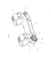
- a tension spring 41 extends through the vertical bore 50 in the attachment 3 and the vertical bore 51 in the base body 2 (see Fig. 11 ).
- the first eyelet 42 of the tension spring 41 is penetrated by a third clamping pin 43, which sits in the bore 44 in the attachment 3.
- the second eyelet 45 of the tension spring 41 is penetrated by a fourth clamping pin 46, which sits in the bore 47 in the base body 2.
- the fifth clamping pin 52 in the bore 53 in the attachment 3 projects into the bore 54 in the extension 14 in the base body 2.
- the diameter of the bore 54 is slightly larger than the diameter of the clamping pin 52. This arrangement prevents the second clamping screw when loosening or tightening 24 too strong lateral pushing away of the essay 3 (see Fig. 12 ).
- the manipulation of the pretilt adjustment is done in five steps:
- the setting wheel 16 must be turned so far until the corresponding surface 20 rests against the contact surface 23.
- the tension spring 41 By the tension spring 41, the contact surface 23 is always against the surfaces on the circumference of the adjusting wheel 16th drawn. Since when turning from one surface to the next, the tension spring 41 is stretched and relaxed again, there is a tactile detent on each surface.
- the angle ⁇ is chosen so that it is less than 90 ° and greater than the angle of self-locking of the material pairing of the wall 31 of the attachment 3 and the spacer plate 32.
- the self-locking describes in mechanics the resistance caused by friction against the displacement of two adjoining bodies.
- the angle at the inclined plane is referred to as the angle of the self-locking, is present in the static friction. If the angle of self-locking is exceeded, sliding friction is present and the two bodies are thus no longer self-locking.
- the size of the angle of self-locking depends on the surface roughness of the material pairing.
- the attachment 3 is thus pulled with its contact surface 23 against the surface 20 of the setting wheel 16 and at the same time with its wall 31 against the spacer plate 32 and this in turn against the wall 30 on the extension 14. Thus, there is a positive connection.
- Points 1 and 2 or points 4 and 5 when handling the adjustment can also be carried out in reverse order.
- the scope mount can basically also be made in two parts (not shown in the figures). This means that the region of the hinge with the front half-shell 5 and the region of the adjusting wheel 16 with the rear half-shell 6 have no connection. Both areas then sit separately on the Picatinny rail 4 or are connected according to the mounting method with the weapon.
- the extension 14 with the circular pin 15 and the setting wheel 16 are not seen in the weft direction rear end of the assembly, but at the front end. Accordingly, the conical connection is then at the rear end of the assembly.
- the thumbwheel 16 and the taper 8 sit in the exemplary embodiment of the invention on the right in the firing direction right side of the scope mount. These elements can also be arranged on the left side.
- extension 14 with the circular pin 15 may be part of the attachment 3.
- the internal thread 29 for the second clamping screw 24 is in this embodiment in consequence of the main body. 2
Abstract
Description
Die Erfindung betrifft eine Zielfernrohrmontage mit einstellbarer Vorneigung, um beim Schuss auf weite Distanzen den Vorneigungswinkel zwischen Zielfernrohr und Lauf derart verändern zu können, dass der vertikale Verstellweg des Zielfernrohrs ausreicht, um es auf die gewünschte Schussentfernung einstellen zu können.The invention relates to a scope mount with adjustable pre-tilt to change the pre-tilt angle between scope and barrel when shooting at long distances so that the vertical displacement of the scope is sufficient to adjust it to the desired shooting distance can.
Nach dem Abfeuern aus einer Schusswaffe folgt das Geschoss einer Flugbahn, deren Krümmung von verschiedenen Einflussfaktoren, wie Geschossgewicht und Geschossgeschwindigkeit abhängig ist. Nach dem Einschießen der Waffe auf beispielsweise 100 m kann durch ein Verstellen des Absehens das Zielfernrohr an verschiedene Schussentfernungen angepasst werden. Der Verstellweg jedes Zielfernrohrs ist jedoch mechanisch beschränkt, so dass beispielsweise nur ein Entfernungsbereich von ca. 50 - 600 m abgedeckt werden kann. Liegt die gewünschte Schussentfernung außerhalb dieses Bereiches, beispielsweise bei 800 m, kann diese durch ein Verstellen des Absehens nicht mehr erreicht werden.After firing from a firearm, the projectile follows a trajectory, the curvature of which depends on various influencing factors, such as projectile weight and projectile velocity. After shooting the weapon at, for example, 100 m, the telescopic sight can be adjusted to different shooting distances by adjusting the reticle. However, the adjustment path of each riflescope is mechanically limited, so that, for example, only a distance range of about 50 - 600 m can be covered. If the desired shooting distance is outside this range, for example at 800 m, this can no longer be achieved by adjusting the reticle.
Zielfernrohre werden mit Hilfe von Zielfernrohrmontagen mit der Schusswaffe verbunden. Im Normalfall liegen dabei die optische Achse des Zielfernrohrs und die Laufseelenachse der Waffe koaxial zueinander. Aufgrund der bei großen Entfernungen zum Ziel stark abfallenden Flugbahn des Geschosses wird in solchen Fällen das Zielfernrohr mit einer vorgeneigten Zielfernrohrmontage auf die Waffe montiert. Dabei sind bei unterschiedlichen Kombinationen von verwendeter Munition, Lauf, Waffensystem, Zielfernrohrmontage, Zielfernrohr und gewünschter Schussentfernung unterschiedliche Vorneigungswinkel nötig, damit der zur Verfügung stehende vertikale Verstellweg des Zielfernrohrs zum Einstellen des Absehens auf unterschiedliche Schussentfernungen ausreicht.Riflescopes are connected to the firearm using riflescope mountings. Normally, the optical axis of the telescopic sight and the barrel axis of the weapon are coaxial with each other. Due to the greatly decreasing at long distances to the target trajectory of the projectile in such cases, the riflescope is mounted with a vorgeneigten scope mount on the weapon. In this case, different pretilt angles are necessary for different combinations of ammunition, barrel, weapon system, scope mount, telescopic sight and desired shot distance, so that the available vertical displacement of the scope is sufficient to set the reticle to different firing ranges.
Ist das Zielfernrohr mit einer Zielfernrohrmontage, welche eine fixe Vorneigung von beispielsweise 20 MOA (Minute Of Angle, Winkelminuten) aufweist, montiert, so kann diese Kombination für einen bestimmten Anwendungsfall passen. Bei einer anderen Kombination kann jedoch ein anderer Vorneigungswinkel nötig sein, um das Absehen des Zielfernrohrs auf die gewünschte Schussentfernung einstellen zu können.If the riflescope is mounted with a riflescope assembly which has a fixed pretilt of, for example, 20 MOA ( M inute O f A ngle, angular minutes), this combination may suit a particular application. However, another combination may require a different pretilt angle be able to set the sight of the riflescope to the desired shooting distance can.
Diesem Problem kann begegnet werden, indem mehrere Zielfernrohrmontagen mit verschiedenen fix integrierten Vorneigungen zur Verfügung stehen. Dies erfordert jedoch eine entsprechende Teilevielfalt und Lagerhaltung. Zudem müsste durch Versuch und Irrtum, also durch mehrfaches Ummontieren, die Zielfernrohrmontage mit der passenden Vorneigung gefunden werden. Eine wesentlich einfachere und praktikablere Lösung für dieses Problem ist eine Zielfernrohrmontage, bei der die Neigung einstellbar ist.This problem can be addressed by having multiple riflescope mountings with different fixed integrated ripples available. However, this requires a corresponding variety of parts and warehousing. In addition, by trial and error, so by multiple remounting, the scope mount with the appropriate pre-tilt would have to be found. A much simpler and more practical solution to this problem is a scope mount where the tilt is adjustable.
Im Stand der Technik sind verschiedene Zielfernrohrmontagen bekannt, bei denen die Vorneigung verändert, bzw. eingestellt werden kann:
- Im
US-Patent Nr. 2951292 - Im
US-Patent Nr. 3340614 - In der US-Patentanmeldung Nr.
US 2004/0144013 A1 - In dem deutschen Gebrauchsmuster Nr.
DE 20 2010 003 668 U1 - Im
US-Patent Nr. 4317304 - Im
US-Patent Nr. 2663083 - Im
US-Patent Nr. 5086566 - Im
US-Patent Nr. 5400539 - Im
US-Patent Nr. 5428915 - Im US-Patent Nr.
US 7121037 B2 - Im US-Patent Nr.
US 6662486 B2 - Im US-Patent Nr.
US 7140143 B1 - Im US-Patent Nr.
US 8079171 B2 - Im US-Patent Nr.
US 7543405 B1 - Im US-Patent Nr.
US 8240075 B1
- in the
U.S. Patent No. 2951292 - in the
U.S. Patent No. 3,340,614 - In US patent application no.
US 2004/0144013 A1 - In the German utility model no.
DE 20 2010 003 668 U1 - in the
U.S. Patent No. 4,317,304 - in the
U.S. Patent No. 2,663,083 - in the
U.S. Patent No. 5,086,566 - in the
U.S. Patent No. 5,400,539 - in the
U.S. Patent No. 5,428,915 - In US Pat.
US 7121037 B2 - In US Pat.
US 6662486 B2 - In US Pat.
US 7140143 B1 - In US Pat.
US 8079171 B2 - In US Pat.
US 7543405 B1 - In US Pat.
US 8240075 B1
Eine Zielfernrohrmontage mit einstellbarer Vorneigung kann in der Jagd oder beim Sportschießen eingesetzt werden. Insbesondere jedoch auf militärisch genutzten Waffen mit besonders großer Reichweite und entsprechend leistungsstarken Kalibern bringt eine solche Montage entscheidende Vorteile für den Anwender.A rifle scope mount with adjustable forward tilt can be used in hunting or sport shooting. However, especially on military-used weapons with a particularly long range and correspondingly powerful calibers, such an assembly brings decisive advantages for the user.
Ein naheliegender Aufbau einer solchen Zielfernrohrmontage besteht aus einem scharnierenden Abschnitt und einem Abschnitt mit einem Verstellmechanismus. Bekannte Scharniere, wie in der in der
Absolute Zuverlässigkeit und Robustheit unter rauesten Einsatzbedingungen ist insbesondere bei militärisch genutzten Waffen von entscheidender Bedeutung. Um dies zu erreichen soll die Zielfernrohrmontage aus möglichst wenigen Einzelteilen bestehen und die Verbindung der einzelnen Komponenten soll formschlüssig und nicht reibschlüssig sein. Zudem sollen möglichst wenig verlierbare Teile verbaut sein, was bedeutet, dass die Zielfernrohrmontage zum Einstellen der Vorneigung nach Möglichkeit nicht zerlegt oder von der Waffe abgenommen werden muss. Von besonderer Wichtigkeit ist auch eine möglichst einfache Handhabung der Verstellung, damit Bedienfehler weitestgehend ausgeschlossen werden können.Absolute reliability and ruggedness in the harshest of conditions is crucial, especially for military-grade weapons. To achieve this, the scope mount from as few as possible Parts exist and the connection of the individual components should be positive and not frictionally. In addition, as little as possible parts to be lost should be installed, which means that the scope mount for adjusting the tilt should not be disassembled or removed from the weapon if possible. Of particular importance is the simplest possible handling of the adjustment so that operator error can be largely excluded.
Die Aufgabe der Erfindung besteht darin, den geschilderten Nachteil des Standes der Technik zu überwinden.The object of the invention is to overcome the described disadvantage of the prior art.
Die Aufgabe der Erfindung wird durch eine Zielfernrohrmontage mit einstellbarer Vorneigung gelöst, die dadurch gekennzeichnet ist dass ein Grundkörper und ein Aufsatz durch die Anordnung einer Klemmschraube in einem Winkel größer der Selbsthemmung der Materialpaarung und kleiner 90° eine formschlüssige Verbindung aufweisen.The object of the invention is achieved by a riflescope mounting with adjustable tilt, which is characterized in that a base body and an attachment by the arrangement of a clamping screw at an angle greater than the self-locking material pairing and less than 90 ° have a positive connection.
Die Aufgabe der Erfindung wird ferner durch Zielfernrohrmontage mit einstellbarer Vorneigung gelöst, die dadurch gekennzeichnet ist, dass der Grundkörper und der Aufsatz eine Kegelverbindung aufweisen.The object of the invention is further achieved by telescopic sight mounting with adjustable pre-tilt, which is characterized in that the base body and the attachment have a conical connection.
Die erfindungsgemäße Zielfernrohrmontage erfüllt die genannten Anforderungen in vorzüglicher Weise.The scope mount according to the invention meets the requirements mentioned in an excellent manner.
Eine besonders vorteilhafte Ausführung wird nachstehend anhand der Figuren näher erläutert.A particularly advantageous embodiment is explained below with reference to the figures.
Es zeigen:
- Fig. 1
- eine erfindungsgemäße Zielfernrohrmontage 1 in perspektivischer Darstellung, montiert auf einer Picatinny-
Schiene 4, - Fig. 2
- eine Seitenansicht von rechts mit Angabe der Schnittebenen der Zielfernrohrmontage 1,
- Fig. 3
- eine erste Explosionszeichnung der erfindungsgemäßen Zielfernrohrmontage 1,
- Fig. 4
- eine perspektivische Darstellung des Aufsatzes 3,
- Fig. 5
- eine Schnittdarstellung durch das Scharnier,
- Fig. 6
- eine perspektivische Darstellung des Aufsatzes 3 mit Blick
auf das Stellrad 16, - Fig. 7
- eine zweite Explosionszeichnung der erfindungsgemäßen Zielfernrohrmontage 1,
- Fig. 8
- eine perspektivische Darstellung des Stellrades 16,
- Fig. 9
- eine Schnittdarstellung durch den Bereich des Stellrades 16 mit der zweiten Klemmschraube 24,
- Fig. 10
- eine perspektivische Darstellung der zweiten Klemmschraube 24,
- Fig. 11
- eine Schnittdarstellung durch den Bereich der Zugfeder 41 und
- Fig. 12
- eine Schnittdarstellung durch den Bereich des fünften Spannstiftes 52.
- Fig. 1
- an
inventive scope mount 1 in a perspective view, mounted on aPicatinny rail 4, - Fig. 2
- a side view from the right with indication of the cutting planes of the telescopic sight mounting 1,
- Fig. 3
- a first exploded view of the
scope mount 1 according to the invention, - Fig. 4
- a perspective view of the
article 3, - Fig. 5
- a sectional view through the hinge,
- Fig. 6
- a perspective view of the
article 3 with a view of thesetting wheel 16, - Fig. 7
- a second exploded view of the
scope mount 1 according to the invention, - Fig. 8
- a perspective view of the
setting wheel 16, - Fig. 9
- a sectional view through the region of the
adjusting wheel 16 with thesecond clamping screw 24, - Fig. 10
- a perspective view of the
second clamping screw 24, - Fig. 11
- a sectional view through the region of the
tension spring 41 and - Fig. 12
- a sectional view through the region of the fifth clamping pin 52nd
Der Grundkörper 2 weist einen Kegelzapfen 8 mit einer Bohrung 9 auf (siehe
Im verbauten Zustand (siehe
Der Grundkörper 2 weist einen Fortsatz 14 und dieser wiederum einen Kreiszapfen 15 auf, auf welchem das Stellrad 16 drehbar gelagert ist (siehe
Das Stellrad 16 weist auf seinem Umfang beispielsweise acht ebene Flächen mit zugeordneten Beschriftungen auf. Zur Verdeutlichung der Funktion wird beispielhaft die Fläche 20 herausgegriffen, welcher die Beschriftung "20" zugeordnet ist. Jeder Fläche ist ein bestimmter Winkel der Vorneigung zugeordnet. Der notwendige Abstand "A" in
Aus
Das Langloch 22 wird von einer zweiten Klemmschraube 24 (siehe
Durch fertigungsbedingte Toleranzen am Durchmesser des Kegelzapfens 8 und am Durchmesser der Kegelsenkung 10 ergibt sich zwischen der Wandung 30 am Fortsatz 14 und der Wandung 31 am Aufsatz 3 ein mehr oder weniger großer Spalt. Dieser Spalt wird durch Distanzplättchen 32 ausgeglichen. Je nach Größe des Spaltes werden entsprechend viele Distanzplättchen 32 eingelegt (siehe
Der Fortsatz 14 und der Kreiszapfen 15 weisen eine erste Bohrung 33 und eine zweite Bohrung 34 auf. In diesen Bohrungen sitzt ein erster Spannstift 35 und ein zweiter Spannstift 36. Diese beiden Spannstifte durchgreifen die Bohrungen 37 und 38 in den Distanzplättchen 32 und dienen zu deren Positionierung (siehe
Die Ausfräsungen 39 und 40 sorgen für Kollisionsfreiheit zu den Spannstiften 35 und 36 (siehe
Eine Zugfeder 41 verläuft durch die vertikale Bohrung 50 im Aufsatz 3 und die vertikale Bohrung 51 im Grundkörper 2 (siehe
Die erste Öse 42 der Zugfeder 41 wird von einem dritten Spannstift 43 durchgriffen, welcher in der Bohrung 44 im Aufsatz 3 sitzt.The
Die zweite Öse 45 der Zugfeder 41 wird von einem vierten Spannstift 46 durchgriffen, welcher in der Bohrung 47 im Grundkörper 2 sitzt.The
Der fünfte Spannstift 52 in der Bohrung 53 im Aufsatz 3 ragt in die Bohrung 54 im Fortsatz 14 im Grundkörper 2. Dabei ist der Durchmesser der Bohrung 54 geringfügig größer als der Durchmesser des Spannstiftes 52. Diese Anordnung verhindert beim Lösen bzw. Anziehen der zweiten Klemmschraube 24 ein zu starkes seitliches Wegdrücken des Aufsatzes 3 (siehe
Die Handhabung der Verstellung der Vorneigung geschieht in fünf Schritten:The manipulation of the pretilt adjustment is done in five steps:
Hierbei ist eine Umdrehung der Schraube ausreichend.Here, one turn of the screw is sufficient.
Je nach der Steigung des Gewindes sind ca. zwei Umdrehungen der Schraube ausreichend. Da nun beide Klemmschrauben gelöst sind sorgt die Druckfeder 48 in der Bohrung 49 (siehe
Dabei muss das Stellrad 16 soweit verdreht werden, bis die entsprechende Fläche 20 an der Anlagefläche 23 anliegt. Durch die Zugfeder 41 wird die Anlagefläche 23 immer gegen die Flächen am Umfang des Stellrades 16 gezogen. Da beim Drehen von einer Fläche zur nächsten die Zugfeder 41 gedehnt und wieder entspannt wird, entsteht bei jeder Fläche eine fühlbare Rastung.In this case, the
Der Winkel ß ist so gewählt, dass er kleiner 90° und größer als der Winkel der Selbsthemmung der Materialpaarung der Wandung 31 des Aufsatzes 3 und der Distanzplättchen 32 ist.The angle β is chosen so that it is less than 90 ° and greater than the angle of self-locking of the material pairing of the
Die Selbsthemmung beschreibt in der Mechanik den durch Reibung verursachten Widerstand gegen das Verschieben zweier aneinanderliegender Körper. Dabei wird als Winkel der Selbsthemmung der Winkel an der schiefen Ebene bezeichnet, in dem Haftreibung vorliegt. Wird der Winkel der Selbsthemmung überschritten, liegt Gleitreibung vor und die beiden Körper sind somit nicht mehr selbsthemmend. Die Größe des Winkels der Selbsthemmung ist dabei abhängig von der Oberflächenrauheit der Werkstoffpaarung.The self-locking describes in mechanics the resistance caused by friction against the displacement of two adjoining bodies. In this case, the angle at the inclined plane is referred to as the angle of the self-locking, is present in the static friction. If the angle of self-locking is exceeded, sliding friction is present and the two bodies are thus no longer self-locking. The size of the angle of self-locking depends on the surface roughness of the material pairing.
Der Aufsatz 3 wird somit mit seiner Anlagefläche 23 gegen die Fläche 20 des Stellrades 16 und gleichzeitig mit seiner Wandung 31 gegen die Distanzplättchen 32 und diese wiederum gegen die Wandung 30 am Fortsatz 14 gezogen. Somit liegt eine formschlüssige Verbindung vor. Würde die zweite Klemmschraube 24 quer zur Schussrichtung, also im 90°-Winkel zu den Flächen 30 und 31 verlaufen, würde eine lediglich reibschlüssige Verbindung vorliegen, da in diesem Fall der Aufsatz 3 nicht mit seiner Anlagefläche 23 gegen die Fläche 20 des Stellrades 16 gezogen würde. Würde der Winkel ß so gewählt, dass er kleiner als der Winkel der Selbsthemmung - somit also innerhalb der Selbsthemmung - der Materialpaarung der Wandung 31 des Aufsatzes 3 und der Distanzplättchen 32 ist, so würde ebenfalls lediglich eine reibschlüssige Verbindung vorliegen, da auch in diesem Fall der Aufsatz 3 nicht mit seiner Anlagefläche 23 gegen die Fläche 20 des Stellrades 16 gezogen wird.The
Die Punkte 1 und 2 bzw. die Punkte 4 und 5 bei der Handhabung der Verstellung können auch in umgekehrter Reihenfolge ausgeführt werden.
Die Zielfernrohrmontage kann grundsätzlich auch zweiteilig ausgeführt sein (nicht in den Figuren dargestellt). Dies bedeutet, dass der Bereich des Scharniers mit der vorderen Halbschale 5 und der Bereich des Stellrades 16 mit der hinteren Halbschale 6 keine Verbindung aufweisen. Beide Bereiche sitzen dann getrennt voneinander auf der Picatinny-Schiene 4 oder sind entsprechend der Montageart mit der Waffe verbunden.The scope mount can basically also be made in two parts (not shown in the figures). This means that the region of the hinge with the front half-
Bei weiteren nicht in den Figuren dargestellten Ausführungsformen der Erfindung befinden sich der Fortsatz 14 mit dem Kreiszapfen 15 und dem Stellrad 16 nicht am in Schussrichtung gesehen hinteren Ende der Montage, sondern an deren vorderen Ende. Dementsprechend liegt die Kegelverbindung dann am hinteren Ende der Montage.In other embodiments of the invention not shown in the figures, the
Das Stellrad 16 und der Kegelzapfen 8 sitzen in der beispielhaften Ausführungsform der Erfindung auf der in Schussrichtung gesehen rechten Seite der Zielfernrohrmontage. Diese Elemente können ebenso auf der linken Seite angeordnet sein.The
In einer weiteren nicht in den Figuren gezeigten Ausführungsform kann der Kegelzapfen 8 Teil des Aufsatzes 3 und die Kegelsenkung 10 in Folge dessen Teil des Grundkörpers 2 sein.In a further embodiment not shown in the figures, the
Bei einer weiteren Variante kann der Fortsatz 14 mit dem Kreiszapfen 15 Teil des Aufsatzes 3 sein. Das Innengewinde 29 für die zweite Klemmschraube 24 befindet sich bei dieser Ausführungsform in Folge dessen im Grundkörper 2.In a further variant, the
- 11
- ZielfernrohrmontageScope Mount
- 22
- Grundkörperbody
- 33
- Aufsatzessay
- 44
- Picatinny-SchienePicatinny rail
- 55
- vordere Halbschalefront half shell
- 66
- hintere Halbschalerear half shell
- 77
- ZielfernrohrScope
- 88th
- Kegelzapfentaper
- 99
-
Bohrung für erste Klemmschraube 12Bore for first clamping
screw 12 - 1010
- Kegelsenkungcountersink
- 1111
-
Innengewinde für erste Klemmschraube 12Internal thread for first clamping
screw 12 - 1212
- erste Klemmschraubefirst clamping screw
- 1313
- Scharnierachsehinge axis
- 1414
- Fortsatzextension
- 1515
- Kreiszapfencircular spigot
- 1616
- Stellradthumbwheel
- 1717
-
Gewindestift als Verliersicherung für das Stellrad 16Grub screw as captive for the
thumbwheel 16 - 1818
- Ringnutring groove
- 1919
-
Innengewinde im Stellrad 16Internal thread in the
setting wheel 16 - 2020
- Flächearea
- 2121
- Riffelungknurl
- 2222
- LanglochLong hole
- 2323
- Anlageflächecontact surface
- 2424
- zweite Klemmschraubesecond clamping screw
- 2525
-
Grundfläche des Kopfes 26 der zweiten Klemmschraube 24Base of the
head 26 of the second clamping screw 24th - 2626
-
Kopf der zweiten Klemmschraube 24Head of the
second clamping screw 24 - 2727
-
Fläche des Kreiszapfens 15Surface of the
circular pin 15 - 2828
-
Gewindeschaft der zweiten Klemmschraube 24Threaded shaft of the
second clamping screw 24 - 2929
-
Innengewinde im Aufsatz 3Internal thread in the
attachment 3 - 3030
-
Wandung am Fortsatz 14Wall at the
extension 14 - 3131
-
Wandung am Aufsatz 3Wall at the
tower 3 - 3232
- DistanzplättchenShim plates
- 3333
-
erste Bohrung durch Fortsatz 14 und Kreiszapfen 15first bore through
extension 14 and circular pin 15th - 3434
-
zweite Bohrung durch Fortsatz 14 und Kreiszapfen 15second bore through
extension 14 and circular pin 15th - 3535
- erster Spannstiftfirst dowel pin
- 3636
- zweiter Spannstiftsecond clamping pin
- 3737
-
erste Bohrung im Distanzplättchen 32first hole in the
spacer plate 32 - 3838
-
zweite Bohrung im Distanzplättchen 32second bore in the
spacer plate 32 - 3939
-
erste Ausfräsung im Aufsatz 3first cutout in the
attachment 3 - 4040
-
zweite Ausfräsung im Aufsatz 3second cutout in the
attachment 3 - 4141
- Zugfedermainspring
- 4242
- erste Öse der Zugfeder 41first eye of the tension spring 41st
- 4343
- dritter Spannstiftthird dowel pin
- 4444
-
Bohrung im Aufsatz 3Hole in
attachment 3 - 4545
- zweite Öse der Zugfeder 41second eye of the tension spring 41st
- 4646
- vierter Spannstiftfourth tension pin
- 4747
-
Bohrung im Grundkörper 2Bore in the
main body 2 - 4848
- Druckfedercompression spring
- 4949
-
Bohrung für Druckfeder 48Bore for
compression spring 48 - 5050
-
vertikale Bohrung im Aufsatz 3vertical hole in the
attachment 3 - 5151
-
vertikale Bohrung im Grundkörper 2vertical bore in the
main body 2 - 5252
- fünfter Spannstiftfifth tension pin
- 5353
-
Bohrung für fünften Spannstift 52 im Aufsatz 3Bore for
fifth clamping pin 52 in theattachment 3 - 5454
-
Bohrung für fünften Spannstift 52 im Fortsatz 14Bore for
fifth clamping pin 52 in the extension 14th
Claims (9)
Priority Applications (2)
| Application Number | Priority Date | Filing Date | Title |
|---|---|---|---|
| PL13005372T PL2743631T3 (en) | 2012-12-11 | 2013-11-14 | Rifle telescope mounting with adjustable predefined inclination |
| HRP20190879TT HRP20190879T1 (en) | 2012-12-11 | 2019-05-13 | Rifle telescope mounting with adjustable predefined inclination |
Applications Claiming Priority (1)
| Application Number | Priority Date | Filing Date | Title |
|---|---|---|---|
| DE202012011835U DE202012011835U1 (en) | 2012-12-11 | 2012-12-11 | Scope mount with adjustable pre-tilt |
Publications (3)
| Publication Number | Publication Date |
|---|---|
| EP2743631A2 true EP2743631A2 (en) | 2014-06-18 |
| EP2743631A3 EP2743631A3 (en) | 2017-11-15 |
| EP2743631B1 EP2743631B1 (en) | 2019-02-27 |
Family
ID=47711149
Family Applications (1)
| Application Number | Title | Priority Date | Filing Date |
|---|---|---|---|
| EP13005372.1A Active EP2743631B1 (en) | 2012-12-11 | 2013-11-14 | Rifle telescope mounting with adjustable predefined inclination |
Country Status (6)
| Country | Link |
|---|---|
| US (1) | US8893424B2 (en) |
| EP (1) | EP2743631B1 (en) |
| DE (2) | DE202012011835U1 (en) |
| HR (1) | HRP20190879T1 (en) |
| PL (1) | PL2743631T3 (en) |
| TR (1) | TR201907365T4 (en) |
Cited By (2)
| Publication number | Priority date | Publication date | Assignee | Title |
|---|---|---|---|---|
| WO2020132491A1 (en) * | 2018-12-21 | 2020-06-25 | Bravo Company Mfg, Inc. | Firearm accessory mount with angled hardware |
| USD973826S1 (en) | 2019-12-20 | 2022-12-27 | Bravo Company Mfg, Inc. | Firearm accessory mount |
Families Citing this family (10)
| Publication number | Priority date | Publication date | Assignee | Title |
|---|---|---|---|---|
| WO2012099876A1 (en) * | 2011-01-17 | 2012-07-26 | RM Equipment, Inc. | Device for profile rail attachment |
| US9052163B2 (en) * | 2013-08-09 | 2015-06-09 | Weigand Combat Handguns Inc. | Adjustable scope mount for a projectile weapon and methods of using and making thereof |
| NO20150300A1 (en) * | 2015-03-05 | 2016-06-20 | GRS Riflestocks AS | Device for mounting and adjusting a binocular sight on a weapon |
| EP3070428A1 (en) * | 2015-03-18 | 2016-09-21 | Gert Dieterle | Support for a sighting device |
| US10036614B1 (en) * | 2017-01-28 | 2018-07-31 | AIM Sports Inc. | Quick release mechanisms to attach accessories to firearms |
| EP3926289A1 (en) | 2018-03-06 | 2021-12-22 | Qioptiq Limited | Shock attenuation device and method using a pivot mechanism |
| US10935347B2 (en) * | 2019-07-22 | 2021-03-02 | Austin Reis Green | Scope mount for accessory attachments |
| US11162518B1 (en) | 2020-02-28 | 2021-11-02 | Preston R. Macy | Rail clamp assembly |
| CN112361883A (en) * | 2020-09-30 | 2021-02-12 | 武汉高德红外股份有限公司 | Sighting telescope mounting base |
| CN112378292A (en) * | 2020-09-30 | 2021-02-19 | 武汉高德红外股份有限公司 | Sighting telescope mounting base |
Citations (17)
| Publication number | Priority date | Publication date | Assignee | Title |
|---|---|---|---|---|
| US2663083A (en) | 1952-07-01 | 1953-12-22 | William P Harms | Double adjustable rifle telescope mount |
| US2951292A (en) | 1958-04-28 | 1960-09-06 | Maynard P Buehler | Adjustable telescope sight mount |
| US3340614A (en) | 1964-10-19 | 1967-09-12 | James M Leatherwood | Adjustment means for gun sighting scope |
| US4317304A (en) | 1980-01-03 | 1982-03-02 | Bass James S | Range and elevation adjustment for telescopic sight |
| US5086566A (en) | 1990-11-09 | 1992-02-11 | Fontaine Industries | Adjustable telescopic sight mount |
| US5400539A (en) | 1992-05-08 | 1995-03-28 | Bulb Bopper, Inc. | Selectively adjustable firearm scope mount |
| US5428915A (en) | 1993-09-27 | 1995-07-04 | King; Kory A. | Detachable sight mount with elevation adjustment |
| US6662486B2 (en) | 2001-06-18 | 2003-12-16 | Franz Komberger | Universal gun sight mount, adjustable for range |
| US20040144013A1 (en) | 2003-01-25 | 2004-07-29 | Leatherwood James Milner | Rifle scope adjustment invention |
| US7121037B2 (en) | 2004-06-14 | 2006-10-17 | Robert Nils Penney | External adjustable telescopic scope device |
| US7140143B1 (en) | 2005-01-11 | 2006-11-28 | Stephen Ivey | Adjustable rifle scope mount |
| US7543405B1 (en) | 2005-01-11 | 2009-06-09 | Stephen Ivey | Adjustable scope mounting system |
| DE202009017398U1 (en) | 2009-12-22 | 2010-04-01 | G. Recknagel E.K. Precision Tradition Technology | Clamping system for accessories on a Picatinny rail |
| DE202010003668U1 (en) | 2010-03-16 | 2010-09-30 | Manz, Georg | Scope mount with adjustable pre-tilt |
| US8079171B2 (en) | 2008-06-11 | 2011-12-20 | Christopher Gene Barrett | Adjustable rifle telescope system with multiple fixed angle mount setpoints |
| US8079172B2 (en) | 2007-07-30 | 2011-12-20 | Morris Dudney | Portable security device for fishing rods and reels |
| US8240075B1 (en) | 2011-01-13 | 2012-08-14 | Mullin James K | Adjustable bases for sighting devices |
Family Cites Families (12)
| Publication number | Priority date | Publication date | Assignee | Title |
|---|---|---|---|---|
| US1330002A (en) | 1920-02-03 | wales | ||
| US2881524A (en) | 1956-08-09 | 1959-04-14 | Anthony B Simeone | Adjustable gun sights |
| US3270418A (en) | 1964-04-21 | 1966-09-06 | Robert A Simeone | Rifle sight |
| US3471932A (en) * | 1967-12-15 | 1969-10-14 | Alfred O Luning | Mounting device for telescope sight and gun with azimuth and elevation adjusting means |
| WO1996034248A1 (en) | 1993-10-12 | 1996-10-31 | Saco Defense Inc. | Extended-range gun sight mounting system |
| DE29502840U1 (en) | 1995-02-21 | 1995-04-27 | Apel Ernst Gmbh | Rifle scope holder with angle-adjustable rifle scope mounts |
| US6295754B1 (en) * | 1998-10-21 | 2001-10-02 | Rodney H. Otteman | Aiming Device with adjustable height mount and auxiliary equipment mounting features |
| US20100162611A1 (en) * | 2008-12-31 | 2010-07-01 | Machining Technologies, Inc. | Adjustable base for an optic |
| DE202009003210U1 (en) | 2009-03-05 | 2010-07-22 | Blaser Finanzholding Gmbh | Mounting device for a target device on a handgun |
| US8196332B2 (en) * | 2009-05-04 | 2012-06-12 | Brenshok, Llc | Forward scout scope mount for firearm |
| US20120060401A1 (en) | 2010-09-09 | 2012-03-15 | Howard Neufeld | Adjustable Rear Iron Sight for a Fire Arm |
| AT512279B1 (en) | 2012-03-22 | 2013-07-15 | Photonic Optische Geraete Gmbh | Device for adjusting the elevation |
-
2012
- 2012-12-11 DE DE202012011835U patent/DE202012011835U1/en not_active Expired - Lifetime
-
2013
- 2013-02-18 US US13/769,590 patent/US8893424B2/en active Active
- 2013-11-14 DE DE102013019165.3A patent/DE102013019165A1/en not_active Ceased
- 2013-11-14 TR TR2019/07365T patent/TR201907365T4/en unknown
- 2013-11-14 PL PL13005372T patent/PL2743631T3/en unknown
- 2013-11-14 EP EP13005372.1A patent/EP2743631B1/en active Active
-
2019
- 2019-05-13 HR HRP20190879TT patent/HRP20190879T1/en unknown
Patent Citations (17)
| Publication number | Priority date | Publication date | Assignee | Title |
|---|---|---|---|---|
| US2663083A (en) | 1952-07-01 | 1953-12-22 | William P Harms | Double adjustable rifle telescope mount |
| US2951292A (en) | 1958-04-28 | 1960-09-06 | Maynard P Buehler | Adjustable telescope sight mount |
| US3340614A (en) | 1964-10-19 | 1967-09-12 | James M Leatherwood | Adjustment means for gun sighting scope |
| US4317304A (en) | 1980-01-03 | 1982-03-02 | Bass James S | Range and elevation adjustment for telescopic sight |
| US5086566A (en) | 1990-11-09 | 1992-02-11 | Fontaine Industries | Adjustable telescopic sight mount |
| US5400539A (en) | 1992-05-08 | 1995-03-28 | Bulb Bopper, Inc. | Selectively adjustable firearm scope mount |
| US5428915A (en) | 1993-09-27 | 1995-07-04 | King; Kory A. | Detachable sight mount with elevation adjustment |
| US6662486B2 (en) | 2001-06-18 | 2003-12-16 | Franz Komberger | Universal gun sight mount, adjustable for range |
| US20040144013A1 (en) | 2003-01-25 | 2004-07-29 | Leatherwood James Milner | Rifle scope adjustment invention |
| US7121037B2 (en) | 2004-06-14 | 2006-10-17 | Robert Nils Penney | External adjustable telescopic scope device |
| US7140143B1 (en) | 2005-01-11 | 2006-11-28 | Stephen Ivey | Adjustable rifle scope mount |
| US7543405B1 (en) | 2005-01-11 | 2009-06-09 | Stephen Ivey | Adjustable scope mounting system |
| US8079172B2 (en) | 2007-07-30 | 2011-12-20 | Morris Dudney | Portable security device for fishing rods and reels |
| US8079171B2 (en) | 2008-06-11 | 2011-12-20 | Christopher Gene Barrett | Adjustable rifle telescope system with multiple fixed angle mount setpoints |
| DE202009017398U1 (en) | 2009-12-22 | 2010-04-01 | G. Recknagel E.K. Precision Tradition Technology | Clamping system for accessories on a Picatinny rail |
| DE202010003668U1 (en) | 2010-03-16 | 2010-09-30 | Manz, Georg | Scope mount with adjustable pre-tilt |
| US8240075B1 (en) | 2011-01-13 | 2012-08-14 | Mullin James K | Adjustable bases for sighting devices |
Cited By (2)
| Publication number | Priority date | Publication date | Assignee | Title |
|---|---|---|---|---|
| WO2020132491A1 (en) * | 2018-12-21 | 2020-06-25 | Bravo Company Mfg, Inc. | Firearm accessory mount with angled hardware |
| USD973826S1 (en) | 2019-12-20 | 2022-12-27 | Bravo Company Mfg, Inc. | Firearm accessory mount |
Also Published As
| Publication number | Publication date |
|---|---|
| TR201907365T4 (en) | 2019-06-21 |
| US8893424B2 (en) | 2014-11-25 |
| DE202012011835U1 (en) | 2013-01-14 |
| DE102013019165A1 (en) | 2014-06-12 |
| EP2743631B1 (en) | 2019-02-27 |
| HRP20190879T1 (en) | 2019-07-12 |
| EP2743631A3 (en) | 2017-11-15 |
| PL2743631T3 (en) | 2019-10-31 |
| US20140157648A1 (en) | 2014-06-12 |
Similar Documents
| Publication | Publication Date | Title |
|---|---|---|
| EP2743631B1 (en) | Rifle telescope mounting with adjustable predefined inclination | |
| DE2057995C3 (en) | Barrel mount for exchangeable barrels on handguns | |
| EP3420302B1 (en) | Firearm with removable barrel | |
| DE2531620A1 (en) | DOUBLE BARRELS WITH OVER ONE BARRELS | |
| DE102012012917A1 (en) | Tilting mounting with additional stop | |
| DE19742248A1 (en) | Firearm improvements | |
| DE202011052542U1 (en) | Adjustable butt plate | |
| DE102005005232A1 (en) | Fitting unit to connect telescopic sights to firearms has turning front foot to act with front foot plate and rear foot to act with sliding rear foot plate | |
| DE202006004542U1 (en) | Sight fixing device for firearm has baseplate with through aperture in surface facing assembly plate, containing pivot pin | |
| DE3204823C2 (en) | Insert barrel for firing small-caliber projectiles | |
| EP0309707B1 (en) | Insert barrel carrying a device for changing the position of the barrel | |
| EP3755965B1 (en) | Adjustable sighting device for firearms | |
| DE102012000525A1 (en) | Telescopic sight support for supporting e.g. sporting guns, has fastening devices eccentrically fixed on weapon-side assembly device with respect to central transverse axis of fastening devices for mounting telescopic sight | |
| WO2000071963A1 (en) | Adjusting device for a firearm system | |
| EP1102024B1 (en) | Method for adjusting the elevation and traversing position of a gun with three barrels and device for putting into practice such a method | |
| DE102015113500B3 (en) | Muzzle attachment for a silencer | |
| DE3834304C1 (en) | Device for adjusting at least one front barrel end of a weapon having at least three barrels | |
| DE102016203544A1 (en) | Air pistol with adjustable handle | |
| EP3730893B1 (en) | Support unit for supporting a breech unit and a barrel of a firearm, in particular a sports weapon | |
| DE4439204C2 (en) | Insert barrel | |
| EP0080091A1 (en) | Heavy gun trunnion support | |
| EP0117845A1 (en) | Arms sighting device | |
| AT402449B (en) | Adjustable mounting apparatus for weapon sights (aiming devices) | |
| EP3303979B1 (en) | Mount for accessories on hand-held weapons | |
| DE202019106701U1 (en) | Compact mounting device |
Legal Events
| Date | Code | Title | Description |
|---|---|---|---|
| PUAI | Public reference made under article 153(3) epc to a published international application that has entered the european phase |
Free format text: ORIGINAL CODE: 0009012 |
|
| 17P | Request for examination filed |
Effective date: 20131114 |
|
| AK | Designated contracting states |
Kind code of ref document: A2 Designated state(s): AL AT BE BG CH CY CZ DE DK EE ES FI FR GB GR HR HU IE IS IT LI LT LU LV MC MK MT NL NO PL PT RO RS SE SI SK SM TR |
|
| AX | Request for extension of the european patent |
Extension state: BA ME |
|
| RAP1 | Party data changed (applicant data changed or rights of an application transferred) |
Owner name: RECKNAGEL GMBH & CO. KG |
|
| PUAL | Search report despatched |
Free format text: ORIGINAL CODE: 0009013 |
|
| AK | Designated contracting states |
Kind code of ref document: A3 Designated state(s): AL AT BE BG CH CY CZ DE DK EE ES FI FR GB GR HR HU IE IS IT LI LT LU LV MC MK MT NL NO PL PT RO RS SE SI SK SM TR |
|
| AX | Request for extension of the european patent |
Extension state: BA ME |
|
| RIC1 | Information provided on ipc code assigned before grant |
Ipc: F41G 11/00 20060101AFI20171010BHEP Ipc: F41G 1/387 20060101ALI20171010BHEP |
|
| STAA | Information on the status of an ep patent application or granted ep patent |
Free format text: STATUS: REQUEST FOR EXAMINATION WAS MADE |
|
| R17P | Request for examination filed (corrected) |
Effective date: 20180514 |
|
| RBV | Designated contracting states (corrected) |
Designated state(s): AL AT BE BG CH CY CZ DE DK EE ES FI FR GB GR HR HU IE IS IT LI LT LU LV MC MK MT NL NO PL PT RO RS SE SI SK SM TR |
|
| GRAJ | Information related to disapproval of communication of intention to grant by the applicant or resumption of examination proceedings by the epo deleted |
Free format text: ORIGINAL CODE: EPIDOSDIGR1 |
|
| STAA | Information on the status of an ep patent application or granted ep patent |
Free format text: STATUS: GRANT OF PATENT IS INTENDED |
|
| GRAP | Despatch of communication of intention to grant a patent |
Free format text: ORIGINAL CODE: EPIDOSNIGR1 |
|
| INTG | Intention to grant announced |
Effective date: 20180919 |
|
| GRAS | Grant fee paid |
Free format text: ORIGINAL CODE: EPIDOSNIGR3 |
|
| GRAA | (expected) grant |
Free format text: ORIGINAL CODE: 0009210 |
|
| STAA | Information on the status of an ep patent application or granted ep patent |
Free format text: STATUS: THE PATENT HAS BEEN GRANTED |
|
| AK | Designated contracting states |
Kind code of ref document: B1 Designated state(s): AL AT BE BG CH CY CZ DE DK EE ES FI FR GB GR HR HU IE IS IT LI LT LU LV MC MK MT NL NO PL PT RO RS SE SI SK SM TR |
|
| REG | Reference to a national code |
Ref country code: GB Ref legal event code: FG4D Free format text: NOT ENGLISH |
|
| REG | Reference to a national code |
Ref country code: CH Ref legal event code: EP |
|
| REG | Reference to a national code |
Ref country code: AT Ref legal event code: REF Ref document number: 1101999 Country of ref document: AT Kind code of ref document: T Effective date: 20190315 |
|
| REG | Reference to a national code |
Ref country code: IE Ref legal event code: FG4D Free format text: LANGUAGE OF EP DOCUMENT: GERMAN |
|
| REG | Reference to a national code |
Ref country code: DE Ref legal event code: R096 Ref document number: 502013012260 Country of ref document: DE |
|
| REG | Reference to a national code |
Ref country code: HR Ref legal event code: TUEP Ref document number: P20190879 Country of ref document: HR |
|
| REG | Reference to a national code |
Ref country code: NL Ref legal event code: MP Effective date: 20190227 |
|
| REG | Reference to a national code |
Ref country code: LT Ref legal event code: MG4D |
|
| REG | Reference to a national code |
Ref country code: HR Ref legal event code: T1PR Ref document number: P20190879 Country of ref document: HR |
|
| PG25 | Lapsed in a contracting state [announced via postgrant information from national office to epo] |
Ref country code: NO Free format text: LAPSE BECAUSE OF FAILURE TO SUBMIT A TRANSLATION OF THE DESCRIPTION OR TO PAY THE FEE WITHIN THE PRESCRIBED TIME-LIMIT Effective date: 20190527 Ref country code: PT Free format text: LAPSE BECAUSE OF FAILURE TO SUBMIT A TRANSLATION OF THE DESCRIPTION OR TO PAY THE FEE WITHIN THE PRESCRIBED TIME-LIMIT Effective date: 20190627 Ref country code: SE Free format text: LAPSE BECAUSE OF FAILURE TO SUBMIT A TRANSLATION OF THE DESCRIPTION OR TO PAY THE FEE WITHIN THE PRESCRIBED TIME-LIMIT Effective date: 20190227 Ref country code: FI Free format text: LAPSE BECAUSE OF FAILURE TO SUBMIT A TRANSLATION OF THE DESCRIPTION OR TO PAY THE FEE WITHIN THE PRESCRIBED TIME-LIMIT Effective date: 20190227 Ref country code: LT Free format text: LAPSE BECAUSE OF FAILURE TO SUBMIT A TRANSLATION OF THE DESCRIPTION OR TO PAY THE FEE WITHIN THE PRESCRIBED TIME-LIMIT Effective date: 20190227 Ref country code: NL Free format text: LAPSE BECAUSE OF FAILURE TO SUBMIT A TRANSLATION OF THE DESCRIPTION OR TO PAY THE FEE WITHIN THE PRESCRIBED TIME-LIMIT Effective date: 20190227 |
|
| PG25 | Lapsed in a contracting state [announced via postgrant information from national office to epo] |
Ref country code: BG Free format text: LAPSE BECAUSE OF FAILURE TO SUBMIT A TRANSLATION OF THE DESCRIPTION OR TO PAY THE FEE WITHIN THE PRESCRIBED TIME-LIMIT Effective date: 20190527 Ref country code: GR Free format text: LAPSE BECAUSE OF FAILURE TO SUBMIT A TRANSLATION OF THE DESCRIPTION OR TO PAY THE FEE WITHIN THE PRESCRIBED TIME-LIMIT Effective date: 20190528 Ref country code: LV Free format text: LAPSE BECAUSE OF FAILURE TO SUBMIT A TRANSLATION OF THE DESCRIPTION OR TO PAY THE FEE WITHIN THE PRESCRIBED TIME-LIMIT Effective date: 20190227 Ref country code: RS Free format text: LAPSE BECAUSE OF FAILURE TO SUBMIT A TRANSLATION OF THE DESCRIPTION OR TO PAY THE FEE WITHIN THE PRESCRIBED TIME-LIMIT Effective date: 20190227 Ref country code: IS Free format text: LAPSE BECAUSE OF FAILURE TO SUBMIT A TRANSLATION OF THE DESCRIPTION OR TO PAY THE FEE WITHIN THE PRESCRIBED TIME-LIMIT Effective date: 20190627 |
|
| PG25 | Lapsed in a contracting state [announced via postgrant information from national office to epo] |
Ref country code: SK Free format text: LAPSE BECAUSE OF FAILURE TO SUBMIT A TRANSLATION OF THE DESCRIPTION OR TO PAY THE FEE WITHIN THE PRESCRIBED TIME-LIMIT Effective date: 20190227 Ref country code: RO Free format text: LAPSE BECAUSE OF FAILURE TO SUBMIT A TRANSLATION OF THE DESCRIPTION OR TO PAY THE FEE WITHIN THE PRESCRIBED TIME-LIMIT Effective date: 20190227 Ref country code: AL Free format text: LAPSE BECAUSE OF FAILURE TO SUBMIT A TRANSLATION OF THE DESCRIPTION OR TO PAY THE FEE WITHIN THE PRESCRIBED TIME-LIMIT Effective date: 20190227 Ref country code: EE Free format text: LAPSE BECAUSE OF FAILURE TO SUBMIT A TRANSLATION OF THE DESCRIPTION OR TO PAY THE FEE WITHIN THE PRESCRIBED TIME-LIMIT Effective date: 20190227 Ref country code: IT Free format text: LAPSE BECAUSE OF FAILURE TO SUBMIT A TRANSLATION OF THE DESCRIPTION OR TO PAY THE FEE WITHIN THE PRESCRIBED TIME-LIMIT Effective date: 20190227 Ref country code: DK Free format text: LAPSE BECAUSE OF FAILURE TO SUBMIT A TRANSLATION OF THE DESCRIPTION OR TO PAY THE FEE WITHIN THE PRESCRIBED TIME-LIMIT Effective date: 20190227 Ref country code: ES Free format text: LAPSE BECAUSE OF FAILURE TO SUBMIT A TRANSLATION OF THE DESCRIPTION OR TO PAY THE FEE WITHIN THE PRESCRIBED TIME-LIMIT Effective date: 20190227 |
|
| REG | Reference to a national code |
Ref country code: DE Ref legal event code: R097 Ref document number: 502013012260 Country of ref document: DE |
|
| PG25 | Lapsed in a contracting state [announced via postgrant information from national office to epo] |
Ref country code: SM Free format text: LAPSE BECAUSE OF FAILURE TO SUBMIT A TRANSLATION OF THE DESCRIPTION OR TO PAY THE FEE WITHIN THE PRESCRIBED TIME-LIMIT Effective date: 20190227 |
|
| REG | Reference to a national code |
Ref country code: HR Ref legal event code: ODRP Ref document number: P20190879 Country of ref document: HR Payment date: 20191107 Year of fee payment: 7 |
|
| PLBE | No opposition filed within time limit |
Free format text: ORIGINAL CODE: 0009261 |
|
| STAA | Information on the status of an ep patent application or granted ep patent |
Free format text: STATUS: NO OPPOSITION FILED WITHIN TIME LIMIT |
|
| 26N | No opposition filed |
Effective date: 20191128 |
|
| PG25 | Lapsed in a contracting state [announced via postgrant information from national office to epo] |
Ref country code: SI Free format text: LAPSE BECAUSE OF FAILURE TO SUBMIT A TRANSLATION OF THE DESCRIPTION OR TO PAY THE FEE WITHIN THE PRESCRIBED TIME-LIMIT Effective date: 20190227 |
|
| REG | Reference to a national code |
Ref country code: CH Ref legal event code: PL |
|
| PG25 | Lapsed in a contracting state [announced via postgrant information from national office to epo] |
Ref country code: LI Free format text: LAPSE BECAUSE OF NON-PAYMENT OF DUE FEES Effective date: 20191130 Ref country code: MC Free format text: LAPSE BECAUSE OF FAILURE TO SUBMIT A TRANSLATION OF THE DESCRIPTION OR TO PAY THE FEE WITHIN THE PRESCRIBED TIME-LIMIT Effective date: 20190227 Ref country code: LU Free format text: LAPSE BECAUSE OF NON-PAYMENT OF DUE FEES Effective date: 20191114 Ref country code: CH Free format text: LAPSE BECAUSE OF NON-PAYMENT OF DUE FEES Effective date: 20191130 |
|
| REG | Reference to a national code |
Ref country code: BE Ref legal event code: MM Effective date: 20191130 |
|
| PG25 | Lapsed in a contracting state [announced via postgrant information from national office to epo] |
Ref country code: IE Free format text: LAPSE BECAUSE OF NON-PAYMENT OF DUE FEES Effective date: 20191114 Ref country code: FR Free format text: LAPSE BECAUSE OF NON-PAYMENT OF DUE FEES Effective date: 20191130 |
|
| REG | Reference to a national code |
Ref country code: HR Ref legal event code: ODRP Ref document number: P20190879 Country of ref document: HR Payment date: 20201103 Year of fee payment: 8 |
|
| PG25 | Lapsed in a contracting state [announced via postgrant information from national office to epo] |
Ref country code: BE Free format text: LAPSE BECAUSE OF NON-PAYMENT OF DUE FEES Effective date: 20191130 |
|
| PG25 | Lapsed in a contracting state [announced via postgrant information from national office to epo] |
Ref country code: CY Free format text: LAPSE BECAUSE OF FAILURE TO SUBMIT A TRANSLATION OF THE DESCRIPTION OR TO PAY THE FEE WITHIN THE PRESCRIBED TIME-LIMIT Effective date: 20190227 |
|
| PG25 | Lapsed in a contracting state [announced via postgrant information from national office to epo] |
Ref country code: MT Free format text: LAPSE BECAUSE OF FAILURE TO SUBMIT A TRANSLATION OF THE DESCRIPTION OR TO PAY THE FEE WITHIN THE PRESCRIBED TIME-LIMIT Effective date: 20190227 Ref country code: HU Free format text: LAPSE BECAUSE OF FAILURE TO SUBMIT A TRANSLATION OF THE DESCRIPTION OR TO PAY THE FEE WITHIN THE PRESCRIBED TIME-LIMIT; INVALID AB INITIO Effective date: 20131114 |
|
| REG | Reference to a national code |
Ref country code: HR Ref legal event code: ODRP Ref document number: P20190879 Country of ref document: HR Payment date: 20211105 Year of fee payment: 9 |
|
| PG25 | Lapsed in a contracting state [announced via postgrant information from national office to epo] |
Ref country code: MK Free format text: LAPSE BECAUSE OF FAILURE TO SUBMIT A TRANSLATION OF THE DESCRIPTION OR TO PAY THE FEE WITHIN THE PRESCRIBED TIME-LIMIT Effective date: 20190227 |
|
| REG | Reference to a national code |
Ref country code: HR Ref legal event code: ODRP Ref document number: P20190879 Country of ref document: HR Payment date: 20221104 Year of fee payment: 10 |
|
| PGFP | Annual fee paid to national office [announced via postgrant information from national office to epo] |
Ref country code: PL Payment date: 20221104 Year of fee payment: 10 |
|
| REG | Reference to a national code |
Ref country code: HR Ref legal event code: ODRP Ref document number: P20190879 Country of ref document: HR Payment date: 20231107 Year of fee payment: 11 |
|
| PGFP | Annual fee paid to national office [announced via postgrant information from national office to epo] |
Ref country code: GB Payment date: 20231123 Year of fee payment: 11 |
|
| PGFP | Annual fee paid to national office [announced via postgrant information from national office to epo] |
Ref country code: TR Payment date: 20231106 Year of fee payment: 11 Ref country code: HR Payment date: 20231107 Year of fee payment: 11 Ref country code: DE Payment date: 20231130 Year of fee payment: 11 Ref country code: CZ Payment date: 20231103 Year of fee payment: 11 Ref country code: AT Payment date: 20231117 Year of fee payment: 11 |
|
| PGFP | Annual fee paid to national office [announced via postgrant information from national office to epo] |
Ref country code: PL Payment date: 20231106 Year of fee payment: 11 |