EP2749395A1 - Three dimensional co-extruded battery electrodes - Google Patents
Three dimensional co-extruded battery electrodes Download PDFInfo
- Publication number
- EP2749395A1 EP2749395A1 EP13198596.2A EP13198596A EP2749395A1 EP 2749395 A1 EP2749395 A1 EP 2749395A1 EP 13198596 A EP13198596 A EP 13198596A EP 2749395 A1 EP2749395 A1 EP 2749395A1
- Authority
- EP
- European Patent Office
- Prior art keywords
- stripes
- layer
- depositing
- interdigitated
- electrode structure
- Prior art date
- Legal status (The legal status is an assumption and is not a legal conclusion. Google has not performed a legal analysis and makes no representation as to the accuracy of the status listed.)
- Granted
Links
- 239000000463 material Substances 0.000 claims abstract description 49
- 239000011149 active material Substances 0.000 claims abstract description 20
- 238000000151 deposition Methods 0.000 claims abstract description 16
- 239000000758 substrate Substances 0.000 claims abstract description 13
- 238000004519 manufacturing process Methods 0.000 claims abstract description 6
- 239000003792 electrolyte Substances 0.000 claims description 10
- 238000001125 extrusion Methods 0.000 claims description 9
- 238000000034 method Methods 0.000 claims description 9
- 238000009826 distribution Methods 0.000 claims description 6
- 239000011148 porous material Substances 0.000 claims description 4
- 238000010438 heat treatment Methods 0.000 claims 1
- 239000007772 electrode material Substances 0.000 description 7
- 238000011161 development Methods 0.000 description 5
- 238000013461 design Methods 0.000 description 4
- 230000032258 transport Effects 0.000 description 4
- HBBGRARXTFLTSG-UHFFFAOYSA-N Lithium ion Chemical compound [Li+] HBBGRARXTFLTSG-UHFFFAOYSA-N 0.000 description 3
- 210000004027 cell Anatomy 0.000 description 3
- 229910001416 lithium ion Inorganic materials 0.000 description 3
- 239000000203 mixture Substances 0.000 description 3
- 239000003990 capacitor Substances 0.000 description 2
- 239000004020 conductor Substances 0.000 description 2
- 239000011245 gel electrolyte Substances 0.000 description 2
- 230000037427 ion transport Effects 0.000 description 2
- 239000011244 liquid electrolyte Substances 0.000 description 2
- 150000002642 lithium compounds Chemical class 0.000 description 2
- NUJOXMJBOLGQSY-UHFFFAOYSA-N manganese dioxide Chemical compound O=[Mn]=O NUJOXMJBOLGQSY-UHFFFAOYSA-N 0.000 description 2
- 230000008569 process Effects 0.000 description 2
- OKTJSMMVPCPJKN-UHFFFAOYSA-N Carbon Chemical compound [C] OKTJSMMVPCPJKN-UHFFFAOYSA-N 0.000 description 1
- HCHKCACWOHOZIP-UHFFFAOYSA-N Zinc Chemical compound [Zn] HCHKCACWOHOZIP-UHFFFAOYSA-N 0.000 description 1
- 239000010406 cathode material Substances 0.000 description 1
- 210000002421 cell wall Anatomy 0.000 description 1
- 238000006243 chemical reaction Methods 0.000 description 1
- 230000008021 deposition Effects 0.000 description 1
- 238000009792 diffusion process Methods 0.000 description 1
- 238000004146 energy storage Methods 0.000 description 1
- 238000005516 engineering process Methods 0.000 description 1
- 238000002474 experimental method Methods 0.000 description 1
- 238000010304 firing Methods 0.000 description 1
- 239000000446 fuel Substances 0.000 description 1
- 229910002804 graphite Inorganic materials 0.000 description 1
- 239000010439 graphite Substances 0.000 description 1
- 238000003780 insertion Methods 0.000 description 1
- 230000037431 insertion Effects 0.000 description 1
- 229910000625 lithium cobalt oxide Inorganic materials 0.000 description 1
- BFZPBUKRYWOWDV-UHFFFAOYSA-N lithium;oxido(oxo)cobalt Chemical compound [Li+].[O-][Co]=O BFZPBUKRYWOWDV-UHFFFAOYSA-N 0.000 description 1
- 238000012986 modification Methods 0.000 description 1
- 230000004048 modification Effects 0.000 description 1
- 238000012856 packing Methods 0.000 description 1
- 239000007787 solid Substances 0.000 description 1
- 239000011701 zinc Substances 0.000 description 1
- XLOMVQKBTHCTTD-UHFFFAOYSA-N zinc oxide Inorganic materials [Zn]=O XLOMVQKBTHCTTD-UHFFFAOYSA-N 0.000 description 1
- 229960001296 zinc oxide Drugs 0.000 description 1
Images


Classifications
-
- H—ELECTRICITY
- H01—ELECTRIC ELEMENTS
- H01M—PROCESSES OR MEANS, e.g. BATTERIES, FOR THE DIRECT CONVERSION OF CHEMICAL ENERGY INTO ELECTRICAL ENERGY
- H01M4/00—Electrodes
- H01M4/02—Electrodes composed of, or comprising, active material
- H01M4/13—Electrodes for accumulators with non-aqueous electrolyte, e.g. for lithium-accumulators; Processes of manufacture thereof
-
- H—ELECTRICITY
- H01—ELECTRIC ELEMENTS
- H01M—PROCESSES OR MEANS, e.g. BATTERIES, FOR THE DIRECT CONVERSION OF CHEMICAL ENERGY INTO ELECTRICAL ENERGY
- H01M4/00—Electrodes
- H01M4/02—Electrodes composed of, or comprising, active material
- H01M4/04—Processes of manufacture in general
- H01M4/0402—Methods of deposition of the material
- H01M4/0411—Methods of deposition of the material by extrusion
-
- B—PERFORMING OPERATIONS; TRANSPORTING
- B28—WORKING CEMENT, CLAY, OR STONE
- B28B—SHAPING CLAY OR OTHER CERAMIC COMPOSITIONS; SHAPING SLAG; SHAPING MIXTURES CONTAINING CEMENTITIOUS MATERIAL, e.g. PLASTER
- B28B11/00—Apparatus or processes for treating or working the shaped or preshaped articles
- B28B11/24—Apparatus or processes for treating or working the shaped or preshaped articles for curing, setting or hardening
- B28B11/243—Setting, e.g. drying, dehydrating or firing ceramic articles
-
- B—PERFORMING OPERATIONS; TRANSPORTING
- B28—WORKING CEMENT, CLAY, OR STONE
- B28B—SHAPING CLAY OR OTHER CERAMIC COMPOSITIONS; SHAPING SLAG; SHAPING MIXTURES CONTAINING CEMENTITIOUS MATERIAL, e.g. PLASTER
- B28B3/00—Producing shaped articles from the material by using presses; Presses specially adapted therefor
- B28B3/20—Producing shaped articles from the material by using presses; Presses specially adapted therefor wherein the material is extruded
-
- H—ELECTRICITY
- H01—ELECTRIC ELEMENTS
- H01M—PROCESSES OR MEANS, e.g. BATTERIES, FOR THE DIRECT CONVERSION OF CHEMICAL ENERGY INTO ELECTRICAL ENERGY
- H01M4/00—Electrodes
- H01M4/02—Electrodes composed of, or comprising, active material
- H01M4/04—Processes of manufacture in general
- H01M4/0402—Methods of deposition of the material
-
- H—ELECTRICITY
- H01—ELECTRIC ELEMENTS
- H01M—PROCESSES OR MEANS, e.g. BATTERIES, FOR THE DIRECT CONVERSION OF CHEMICAL ENERGY INTO ELECTRICAL ENERGY
- H01M4/00—Electrodes
- H01M4/02—Electrodes composed of, or comprising, active material
- H01M4/04—Processes of manufacture in general
- H01M4/0471—Processes of manufacture in general involving thermal treatment, e.g. firing, sintering, backing particulate active material, thermal decomposition, pyrolysis
-
- H—ELECTRICITY
- H01—ELECTRIC ELEMENTS
- H01M—PROCESSES OR MEANS, e.g. BATTERIES, FOR THE DIRECT CONVERSION OF CHEMICAL ENERGY INTO ELECTRICAL ENERGY
- H01M4/00—Electrodes
- H01M4/02—Electrodes composed of, or comprising, active material
- H01M4/13—Electrodes for accumulators with non-aqueous electrolyte, e.g. for lithium-accumulators; Processes of manufacture thereof
- H01M4/139—Processes of manufacture
-
- H—ELECTRICITY
- H01—ELECTRIC ELEMENTS
- H01M—PROCESSES OR MEANS, e.g. BATTERIES, FOR THE DIRECT CONVERSION OF CHEMICAL ENERGY INTO ELECTRICAL ENERGY
- H01M4/00—Electrodes
- H01M4/02—Electrodes composed of, or comprising, active material
- H01M4/36—Selection of substances as active materials, active masses, active liquids
- H01M4/362—Composites
- H01M4/366—Composites as layered products
-
- H—ELECTRICITY
- H01—ELECTRIC ELEMENTS
- H01M—PROCESSES OR MEANS, e.g. BATTERIES, FOR THE DIRECT CONVERSION OF CHEMICAL ENERGY INTO ELECTRICAL ENERGY
- H01M4/00—Electrodes
- H01M4/02—Electrodes composed of, or comprising, active material
- H01M4/36—Selection of substances as active materials, active masses, active liquids
- H01M4/48—Selection of substances as active materials, active masses, active liquids of inorganic oxides or hydroxides
- H01M4/52—Selection of substances as active materials, active masses, active liquids of inorganic oxides or hydroxides of nickel, cobalt or iron
- H01M4/525—Selection of substances as active materials, active masses, active liquids of inorganic oxides or hydroxides of nickel, cobalt or iron of mixed oxides or hydroxides containing iron, cobalt or nickel for inserting or intercalating light metals, e.g. LiNiO2, LiCoO2 or LiCoOxFy
-
- H—ELECTRICITY
- H01—ELECTRIC ELEMENTS
- H01M—PROCESSES OR MEANS, e.g. BATTERIES, FOR THE DIRECT CONVERSION OF CHEMICAL ENERGY INTO ELECTRICAL ENERGY
- H01M4/00—Electrodes
- H01M4/86—Inert electrodes with catalytic activity, e.g. for fuel cells
- H01M4/88—Processes of manufacture
- H01M4/8825—Methods for deposition of the catalytic active composition
-
- H—ELECTRICITY
- H01—ELECTRIC ELEMENTS
- H01M—PROCESSES OR MEANS, e.g. BATTERIES, FOR THE DIRECT CONVERSION OF CHEMICAL ENERGY INTO ELECTRICAL ENERGY
- H01M4/00—Electrodes
- H01M4/86—Inert electrodes with catalytic activity, e.g. for fuel cells
- H01M4/88—Processes of manufacture
- H01M4/8878—Treatment steps after deposition of the catalytic active composition or after shaping of the electrode being free-standing body
- H01M4/8882—Heat treatment, e.g. drying, baking
-
- B—PERFORMING OPERATIONS; TRANSPORTING
- B29—WORKING OF PLASTICS; WORKING OF SUBSTANCES IN A PLASTIC STATE IN GENERAL
- B29C—SHAPING OR JOINING OF PLASTICS; SHAPING OF MATERIAL IN A PLASTIC STATE, NOT OTHERWISE PROVIDED FOR; AFTER-TREATMENT OF THE SHAPED PRODUCTS, e.g. REPAIRING
- B29C48/00—Extrusion moulding, i.e. expressing the moulding material through a die or nozzle which imparts the desired form; Apparatus therefor
- B29C48/03—Extrusion moulding, i.e. expressing the moulding material through a die or nozzle which imparts the desired form; Apparatus therefor characterised by the shape of the extruded material at extrusion
- B29C48/07—Flat, e.g. panels
-
- B—PERFORMING OPERATIONS; TRANSPORTING
- B29—WORKING OF PLASTICS; WORKING OF SUBSTANCES IN A PLASTIC STATE IN GENERAL
- B29C—SHAPING OR JOINING OF PLASTICS; SHAPING OF MATERIAL IN A PLASTIC STATE, NOT OTHERWISE PROVIDED FOR; AFTER-TREATMENT OF THE SHAPED PRODUCTS, e.g. REPAIRING
- B29C48/00—Extrusion moulding, i.e. expressing the moulding material through a die or nozzle which imparts the desired form; Apparatus therefor
- B29C48/16—Articles comprising two or more components, e.g. co-extruded layers
- B29C48/18—Articles comprising two or more components, e.g. co-extruded layers the components being layers
- B29C48/21—Articles comprising two or more components, e.g. co-extruded layers the components being layers the layers being joined at their surfaces
-
- B—PERFORMING OPERATIONS; TRANSPORTING
- B29—WORKING OF PLASTICS; WORKING OF SUBSTANCES IN A PLASTIC STATE IN GENERAL
- B29L—INDEXING SCHEME ASSOCIATED WITH SUBCLASS B29C, RELATING TO PARTICULAR ARTICLES
- B29L2031/00—Other particular articles
- B29L2031/34—Electrical apparatus, e.g. sparking plugs or parts thereof
- B29L2031/3468—Batteries, accumulators or fuel cells
-
- H—ELECTRICITY
- H01—ELECTRIC ELEMENTS
- H01M—PROCESSES OR MEANS, e.g. BATTERIES, FOR THE DIRECT CONVERSION OF CHEMICAL ENERGY INTO ELECTRICAL ENERGY
- H01M4/00—Electrodes
- H01M4/02—Electrodes composed of, or comprising, active material
- H01M2004/021—Physical characteristics, e.g. porosity, surface area
-
- H—ELECTRICITY
- H01—ELECTRIC ELEMENTS
- H01M—PROCESSES OR MEANS, e.g. BATTERIES, FOR THE DIRECT CONVERSION OF CHEMICAL ENERGY INTO ELECTRICAL ENERGY
- H01M4/00—Electrodes
- H01M4/86—Inert electrodes with catalytic activity, e.g. for fuel cells
- H01M4/88—Processes of manufacture
- H01M4/8825—Methods for deposition of the catalytic active composition
- H01M4/8864—Extrusion
-
- Y—GENERAL TAGGING OF NEW TECHNOLOGICAL DEVELOPMENTS; GENERAL TAGGING OF CROSS-SECTIONAL TECHNOLOGIES SPANNING OVER SEVERAL SECTIONS OF THE IPC; TECHNICAL SUBJECTS COVERED BY FORMER USPC CROSS-REFERENCE ART COLLECTIONS [XRACs] AND DIGESTS
- Y02—TECHNOLOGIES OR APPLICATIONS FOR MITIGATION OR ADAPTATION AGAINST CLIMATE CHANGE
- Y02E—REDUCTION OF GREENHOUSE GAS [GHG] EMISSIONS, RELATED TO ENERGY GENERATION, TRANSMISSION OR DISTRIBUTION
- Y02E60/00—Enabling technologies; Technologies with a potential or indirect contribution to GHG emissions mitigation
- Y02E60/10—Energy storage using batteries
-
- Y—GENERAL TAGGING OF NEW TECHNOLOGICAL DEVELOPMENTS; GENERAL TAGGING OF CROSS-SECTIONAL TECHNOLOGIES SPANNING OVER SEVERAL SECTIONS OF THE IPC; TECHNICAL SUBJECTS COVERED BY FORMER USPC CROSS-REFERENCE ART COLLECTIONS [XRACs] AND DIGESTS
- Y02—TECHNOLOGIES OR APPLICATIONS FOR MITIGATION OR ADAPTATION AGAINST CLIMATE CHANGE
- Y02E—REDUCTION OF GREENHOUSE GAS [GHG] EMISSIONS, RELATED TO ENERGY GENERATION, TRANSMISSION OR DISTRIBUTION
- Y02E60/00—Enabling technologies; Technologies with a potential or indirect contribution to GHG emissions mitigation
- Y02E60/30—Hydrogen technology
- Y02E60/50—Fuel cells
-
- Y—GENERAL TAGGING OF NEW TECHNOLOGICAL DEVELOPMENTS; GENERAL TAGGING OF CROSS-SECTIONAL TECHNOLOGIES SPANNING OVER SEVERAL SECTIONS OF THE IPC; TECHNICAL SUBJECTS COVERED BY FORMER USPC CROSS-REFERENCE ART COLLECTIONS [XRACs] AND DIGESTS
- Y02—TECHNOLOGIES OR APPLICATIONS FOR MITIGATION OR ADAPTATION AGAINST CLIMATE CHANGE
- Y02P—CLIMATE CHANGE MITIGATION TECHNOLOGIES IN THE PRODUCTION OR PROCESSING OF GOODS
- Y02P70/00—Climate change mitigation technologies in the production process for final industrial or consumer products
- Y02P70/50—Manufacturing or production processes characterised by the final manufactured product
Definitions
- One area of development includes the manufacture of electrodes by co-extruding conductive materials onto a substrate.
- Two aspects of battery development involve optimizing material density and ion transport. High density means higher packing of material, which leads to higher energy storage. Less dense material results in more electrolyte filling the volume, which enables faster lithium ion transport in the electrolyte, in the case of a lithium ion battery.
- US Patent 7,765,949 discloses a device for extruding and dispensing materials on a substrate, the device has at least two channels for receiving materials and an exit port for extruding the materials onto the substrate.
- US Patent 7,780,812 discloses another such device having a planarized edge surface.
- US Patent 7,922,471 discloses another such device for extruding materials that have an equilibrium shape that does not settle after deposition onto the substrate.
- US Patent Publication 20070279839 discloses a co-extrusion technique employing a honeycomb structure.
- US Patent Publications 20120156364 and 2012015321 disclose a co-extrusion head that combines streams of two or more materials into an interdigitated structure on a substrate, where there are multiple stripes of the materials.
- Three dimensional architectures achieve improved battery performance by reconfiguring the electrode materials currently employed in uniform monolithic batteries.
- a variety of three dimensional structures have been achieved as shown in Figure 1 .
- One example 10 has interdigitated cylindrical cathodes and anodes.
- Another example 12 has interdigitated cathodes and anodes with rectangular cross-sections.
- Yet another example 14 shows an array of cylindrical anodes coated with the thin layer of ion-conducting electrolyte with the remaining free volume filled with the cathode material.
- a last example 16 shows what is referred to as an 'aperiodic sponge' architecture in which the solid network of the sponge serves as the charge insertion cathode, which is coated with an ultrathin layer of ion-conducting electrolyte, and the remaining free volume is filled with an interpenetrating, continuous anode.
- FIG. 2 shows an embodiment of three dimensional electrode structure 20 of a battery.
- this electrode structure is discussed here as being part of a battery, it could be an electrode for any number of structures other than a battery such as an ultracapacitor or fuel cells. Further, the electrode could be the cathode or the anode of a battery.
- the electrode structure has two layers, 22 and 24.
- the layers consist of interdigitated stripes of material.
- the layer 22 has stripes oriented in a first direction.
- the layer 24 has stripes oriented in a second direction, orthogonal to the first direction.
- the interdigitated stripes are of an electrode or active material 26 and a sacrificial material 26.
- the electrode material may be any active conductive material. In the case of a secondary battery, this may be a lithium compound or graphite mixture. In the case of a primary battery the electrode may be part of an alkaline system that uses zinc, and manganese dioxide.
- the material 24 may be a sacrificial or fugitive material.
- the sacrificial material may be burned off in a firing process. This would leave gaps between the stripes of active material.
- the gaps may be filled with a liquid or gel electrolyte.
- the gaps may be filled with a highly porous material that will then be filled with electrolyte.
- the stripes of material other than the active material may consist of the highly porous material and would not be removed. Because it is not actually a sacrificial material, this material will be referred to as the intermediate material.
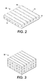
- Figure 3 shows an alternative embodiment of a three dimensional electrode structure 30.
- Each stripe is referred to here as being orthogonal, meaning that the layer is orthogonal to the layer directly underneath it.
- Each layer will run in the same direction as the layer, if there is one, two layers down from the current layer.
- the print heads such as 45 generally deposit two or more materials in adjacent, interdigitated stripes.
- the interdigitated stripes will not typically mix between the materials, although in some embodiments there may be some limited mixing.
- the electrode structure consists of 2 layers, in this embodiment each 125 micrometers (um) tall, stacked in an orthogonal manner to yield a 250 um thick cathode electrode.
- the active material is lithium cobalt oxide in approximately 270 um wide stripes with 170 um wide sacrificial material stripes.
- Figure 4 shows the discharge and charge performance of the electrode structure above.
- the upper set of curves 40 show the charge performance.
- the curves marked with 'C' are the discharge rate performance.
- the notation 2C, 1C, C/2, etc. indicate the different rates of discharge.
- Most batteries are rated at 1C, meaning that a 1,000 mAh battery that is discharged at 1C rate should under ideal conditions provide a current of 1,000mA for one hour.
- 1C is also known as a one-hour discharge.
- C designates the discharge rate, rather than the charging rate.
- 2C may be referred to a half-hour discharge, and C/2 would be a 2 hour discharge.
- Each layer of material may consist of interdigitated stripes of material of the same composition and dimensions of the stripes in the other layers, or they may be of different dimensions.
- the arrangement of the stripes may be symmetric.
- the terms 'symmetric' and 'asymmetric' as used here refer to how the stripes of material are distributed in a volume. In Figure 6 , the stripes such as 50 are uniformly distributed. This may be more easily seen by looking at the upper layer relative to the wire frame 52.
- Figure 7 shows another embodiment of a two layer structure that is asymmetric. As mentioned above, asymmetric refers to the distribution of the stripes within the volume. In Figure 7 , the second layer has the right-most stripe up against the battery cell wall. Figure 8 shows a three layer stack.
- Figure 9 shows the resulting performance.
- the two layer symmetric design of Figure 6 has the greatest specific capacity and better overall performance than the embodiment above with the larger stripes of active material.
- the two layer asymmetric design does not perform as well as the symmetric design but still outperforms the embodiment with larger stripes of active material.
- the three layer stack performed comparably to the two layer stack using LCO as the active material with stripes of material set at 62.5 um. It is possible that if the use of a different electrode material was utilized or a different discharge rate, it is possible the three layer stack may outperform the two layer stack design by a larger margin.
- the manufacture of these structures using the print head of Figure 5 may be accomplished by depositing these layers on the substrate. Either the substrate may be moved past the print head in multiple passes, or the print head may move by the substrate in multiple passes. Alternatively, two different print heads may be used where each print head prints on alternating layer of material. Each pass deposits another layer of electrodes. In order to deposit them orthogonally, either the print head or the substrate will need to be turned to deposit the next layer.
- the structured three dimensional electrode allows for shorter transport distances, increasing the energy and power density of a battery.
- the short transport distances exist because of the fine co-extruded layers that when orthogonally stacked to form a woven like structure help to further reduce transport distances.
- the focus is on maximizing the rate of lithium-ion transport.
- the three dimensional structures increase the amount of electrode material exposed to electrolyte leading to lower resistive and ohmic losses typically experienced with thicker battery electrode.
- Standard battery electrodes typically have thicknesses in the range of 50-100 um.
- the three dimensional structures discussed here may have thicknesses of over 100 um.
Abstract
Description
- Portable power requirements have driven the development of battery technology to achieve high energy density and good power performance. One area of development includes the manufacture of electrodes by co-extruding conductive materials onto a substrate. Two aspects of battery development involve optimizing material density and ion transport. High density means higher packing of material, which leads to higher energy storage. Less dense material results in more electrolyte filling the volume, which enables faster lithium ion transport in the electrolyte, in the case of a lithium ion battery.
- The co-extrusion process has been discussed in several US Patents and US Patent Applications. Examples of these types of battery electrodes are discussed in
US Patents 7,765,949 ;7,780,812 ;7,922,471 ; andUS Patent Publications 20070279839 ,20120156364 and20120153211 .US Patent 7,765,949 discloses a device for extruding and dispensing materials on a substrate, the device has at least two channels for receiving materials and an exit port for extruding the materials onto the substrate.US Patent 7,780,812 discloses another such device having a planarized edge surface.US Patent 7,922,471 discloses another such device for extruding materials that have an equilibrium shape that does not settle after deposition onto the substrate.US Patent Publication 20070279839 discloses a co-extrusion technique employing a honeycomb structure.US Patent Publications 20120156364 and2012015321 disclose a co-extrusion head that combines streams of two or more materials into an interdigitated structure on a substrate, where there are multiple stripes of the materials. - In addition to the development of co-extruded materials, development has begun in three dimensional architectures. These three dimensional architectures achieve improved battery performance by reconfiguring the electrode materials currently employed in uniform monolithic batteries. A variety of three dimensional structures have been achieved as shown in
Figure 1 . One example 10 has interdigitated cylindrical cathodes and anodes. Another example 12 has interdigitated cathodes and anodes with rectangular cross-sections. Yet another example 14 shows an array of cylindrical anodes coated with the thin layer of ion-conducting electrolyte with the remaining free volume filled with the cathode material. A last example 16 shows what is referred to as an 'aperiodic sponge' architecture in which the solid network of the sponge serves as the charge insertion cathode, which is coated with an ultrathin layer of ion-conducting electrolyte, and the remaining free volume is filled with an interpenetrating, continuous anode. - These architectures do have improved performance but are difficult to manufacture. The realization of the improvements can only occur if someone can manufacture the structures in a cost-efficient manner.
-
-
Figure 1 shows examples of several three dimensional battery structures -
Figure 2 shows an embodiment of a three dimensional electrode structure formed from a co-extrusion device. -
Figure 3 shows another embodiment of a three dimensional electrode structure formed from a co-extrusion device. -
Figure 4 shows a graph of battery performance of a three dimensional battery electrode. -
Figure 5 shows an example of a co-extrusion print head. -
Figure 6 shows an embodiment of a battery having orthogonal layers with symmetric stripe distribution. -
Figure 7 shows an embodiment of a battery having orthogonal layers with asymmetric stripe distribution. -
Figure 8 shows an embodiment of a battery having three orthogonal layers with symmetric distribution. -
Figure 9 shows a graph of discharge performance for a three dimensional battery half-cell. -
Figure 2 shows an embodiment of threedimensional electrode structure 20 of a battery. One should note that while this electrode structure is discussed here as being part of a battery, it could be an electrode for any number of structures other than a battery such as an ultracapacitor or fuel cells. Further, the electrode could be the cathode or the anode of a battery. - In the embodiment of
Figure 2 , the electrode structure has two layers, 22 and 24. The layers consist of interdigitated stripes of material. Thelayer 22 has stripes oriented in a first direction. Thelayer 24 has stripes oriented in a second direction, orthogonal to the first direction. In this embodiment, the interdigitated stripes are of an electrode oractive material 26 and asacrificial material 26. The electrode material may be any active conductive material. In the case of a secondary battery, this may be a lithium compound or graphite mixture. In the case of a primary battery the electrode may be part of an alkaline system that uses zinc, and manganese dioxide. Thematerial 24 may be a sacrificial or fugitive material. - As will be discussed in more detail further, the sacrificial material may be burned off in a firing process. This would leave gaps between the stripes of active material. When the layers are packaged into a battery structure, the gaps may be filled with a liquid or gel electrolyte. Alternative to the liquid or gel electrolyte, the gaps may be filled with a highly porous material that will then be filled with electrolyte. As another alternative, the stripes of material other than the active material may consist of the highly porous material and would not be removed. Because it is not actually a sacrificial material, this material will be referred to as the intermediate material.
-
Figure 3 shows an alternative embodiment of a threedimensional electrode structure 30. In this embodiment, there are six layers of interdigitated stripes. Each stripe is referred to here as being orthogonal, meaning that the layer is orthogonal to the layer directly underneath it. Each layer will run in the same direction as the layer, if there is one, two layers down from the current layer. There is no limitation as to the number of layers other than the desire of the system designer. - These structures may be manufactured by any of the embodiments of the co-extrusion print heads discussed above and shown in
Figure 5 . The print heads such as 45 generally deposit two or more materials in adjacent, interdigitated stripes. The interdigitated stripes will not typically mix between the materials, although in some embodiments there may be some limited mixing. - Using one of these types of print heads, a first experimental realization of three dimensional electrode occurred. The electrode structure consists of 2 layers, in this embodiment each 125 micrometers (um) tall, stacked in an orthogonal manner to yield a 250 um thick cathode electrode. In this particular experiment, the active material is lithium cobalt oxide in approximately 270 um wide stripes with 170 um wide sacrificial material stripes.
-
Figure 4 shows the discharge and charge performance of the electrode structure above. The upper set ofcurves 40 show the charge performance. The curves marked with 'C' are the discharge rate performance. Thenotation - Each layer of material may consist of interdigitated stripes of material of the same composition and dimensions of the stripes in the other layers, or they may be of different dimensions. The arrangement of the stripes may be symmetric. The terms 'symmetric' and 'asymmetric' as used here refer to how the stripes of material are distributed in a volume. In
Figure 6 , the stripes such as 50 are uniformly distributed. This may be more easily seen by looking at the upper layer relative to thewire frame 52. - The previous embodiments, discussed above, have active materials in regions that are 270 um wide and 163 um wide stripes of the intermediate material. The structure shown in
Figure 6 has both active and intermediate materials are in 62.5 um wide stripes.Figure 7 shows another embodiment of a two layer structure that is asymmetric. As mentioned above, asymmetric refers to the distribution of the stripes within the volume. InFigure 7 , the second layer has the right-most stripe up against the battery cell wall.Figure 8 shows a three layer stack. -
Figure 9 shows the resulting performance. The two layer symmetric design ofFigure 6 has the greatest specific capacity and better overall performance than the embodiment above with the larger stripes of active material. The two layer asymmetric design does not perform as well as the symmetric design but still outperforms the embodiment with larger stripes of active material. The three layer stack performed comparably to the two layer stack using LCO as the active material with stripes of material set at 62.5 um. It is possible that if the use of a different electrode material was utilized or a different discharge rate, it is possible the three layer stack may outperform the two layer stack design by a larger margin. - The manufacture of these structures using the print head of
Figure 5 , or one similar, may be accomplished by depositing these layers on the substrate. Either the substrate may be moved past the print head in multiple passes, or the print head may move by the substrate in multiple passes. Alternatively, two different print heads may be used where each print head prints on alternating layer of material. Each pass deposits another layer of electrodes. In order to deposit them orthogonally, either the print head or the substrate will need to be turned to deposit the next layer. - In this manner, the structured three dimensional electrode allows for shorter transport distances, increasing the energy and power density of a battery. The short transport distances exist because of the fine co-extruded layers that when orthogonally stacked to form a woven like structure help to further reduce transport distances. In the case of a lithium compound, the focus is on maximizing the rate of lithium-ion transport. The three dimensional structures increase the amount of electrode material exposed to electrolyte leading to lower resistive and ohmic losses typically experienced with thicker battery electrode. Standard battery electrodes typically have thicknesses in the range of 50-100 um. The three dimensional structures discussed here may have thicknesses of over 100 um. These electrodes enable greater power and energy density in a similar if not smaller footprint than conventional prismatic and wound battery cells, while also reducing the number of inactive layers, such as separators, current collectors, in a prismatic or wound stack.
- Because the three dimensional structures presented increase the amount of electrode material surface area exposed to electrolyte, this supports faster diffusion behavior within a battery cell and has advantages for super capacitor and ultra-capacitor electrodes where the amount of electrode material exposed is critical for electrolytic reactions.
- It will be appreciated that several of the above-disclosed and other features and functions, or alternatives thereof, may be desirably combined into many other different systems or applications. Also that various presently unforeseen or unanticipated alternatives, modifications, variations, or improvements therein may be subsequently made by those skilled in the art which are also intended to be encompassed by the following claims.
Claims (15)
- A three dimensional electrode structure, comprising:a first layer of interdigitated stripes of material oriented in a first direction; anda second layer of interdigitated stripes of material oriented in a second direction residing on the first layer of interdigitated stripes of material.
- The three dimensional electrode structure of claim 1, wherein the first and second layers of interdigitated stripes comprise stripes of an active material and stripes of an intermediate material.
- The three dimensional electrode structure of claim 2, wherein the stripes of active material are wider than the stripes of the intermediate material, or wherein the stripes of active material and the stripes of intermediate material have the same width.
- The three dimensional electrode structure of claim 2 or claim 3, wherein the second layer of interdigitated stripes has a symmetric distribution of stripes with the first layer, or wherein the second layer of interdigitated stripes has an asymmetric distribution of stripes with the second layer.
- The three dimensional electrode structure of any of claims 2 to 4, wherein the intermediate material comprises one of a pure electrolyte or a highly porous material having electrolyte in open space in the porous material.
- The three dimensional electrode structure of any of the preceding claims, wherein the first and second layers are of different heights.
- The three dimensional electrode structure of any of the preceding claims, further comprising a third layer of interdigitated stripes of material oriented in the first direction.
- The three dimensional electrode structure of any of the preceding claims, wherein the three dimensional electrode structure has a thickness of more than 100 micrometers.
- A method of manufacturing a three dimensional electrode structure, comprising:depositing a first layer of interdigitated stripes of an active material and an intermediate material on a substrate in a first direction; anddepositing a second layer of interdigitated stripes of the active material and the intermediate material on the first layer in a second direction orthogonal to the first direction.
- The method of claim 9, further comprising:removing the intermediate material from the first and second layers, leaving stripes of the active material with gaps between the stripes of active material; andfelling the gaps between the stripes of active material with an electrolyte.
- The method of claim 10, wherein removing the intermediate material comprises heating the structure to burn off the intermediate material.
- The method of any of claims 9 to 11, wherein depositing the first and second layers comprises one ofi) passing the substrate past a co-extrusion print head multiple times;ii) depositing the layers with multiple passes of a co-extrusion print head past the substrate; and,iii) depositing the first layer with a first print head and the second layer with a second print head.
- The method of any of claims 9 to 12, wherein depositing the second layer comprises depositing the second layer with a different thickness than the first layer, and/or depositing the second layer with a different interdigitated pattern than the first layer.
- The method of any of claims 9 to 13, wherein depositing one of the first and second layers comprises depositing interdigitated stripes of active material wider than the sacrificial material.
- The method of any of claims 9 to 13, wherein depositing one of the first and second layers comprise depositing interdigitated stripes of active material having a same width as the sacrificial material.
Applications Claiming Priority (1)
| Application Number | Priority Date | Filing Date | Title |
|---|---|---|---|
| US13/727,993 US9590232B2 (en) | 2012-12-27 | 2012-12-27 | Three dimensional co-extruded battery electrodes |
Publications (2)
| Publication Number | Publication Date |
|---|---|
| EP2749395A1 true EP2749395A1 (en) | 2014-07-02 |
| EP2749395B1 EP2749395B1 (en) | 2016-08-10 |
Family
ID=49920023
Family Applications (1)
| Application Number | Title | Priority Date | Filing Date |
|---|---|---|---|
| EP13198596.2A Active EP2749395B1 (en) | 2012-12-27 | 2013-12-19 | Three dimensional co-extruded battery electrodes |
Country Status (6)
| Country | Link |
|---|---|
| US (2) | US9590232B2 (en) |
| EP (1) | EP2749395B1 (en) |
| JP (1) | JP6404562B2 (en) |
| KR (1) | KR102094662B1 (en) |
| CN (1) | CN103972468B (en) |
| TW (1) | TWI624106B (en) |
Cited By (2)
| Publication number | Priority date | Publication date | Assignee | Title |
|---|---|---|---|---|
| EP2966708A1 (en) * | 2014-07-11 | 2016-01-13 | Palo Alto Research Center, Incorporated | High performance all solid lithium sulfur battery with fast lithium ion conduction |
| CN105609788A (en) * | 2015-12-30 | 2016-05-25 | 中国科学院上海高等研究院 | Construction method for noble metal hollow tube array-based ordered membrane electrode assemblies |
Families Citing this family (12)
| Publication number | Priority date | Publication date | Assignee | Title |
|---|---|---|---|---|
| US10923714B2 (en) | 2012-12-27 | 2021-02-16 | Palo Alto Research Center Incorporated | Structures for interdigitated finger co-extrusion |
| US10800086B2 (en) * | 2013-08-26 | 2020-10-13 | Palo Alto Research Center Incorporated | Co-extrusion of periodically modulated structures |
| US9855578B2 (en) * | 2013-12-12 | 2018-01-02 | Palo Alto Research Center Incorporated | Co-extrusion print head with edge bead reduction |
| KR102568787B1 (en) | 2015-09-21 | 2023-08-21 | 삼성전자주식회사 | Cathode of three dimensional lithium secondary battery and method of fabricating the same |
| KR102514595B1 (en) | 2015-10-12 | 2023-03-27 | 삼성전자주식회사 | Three dimensional electrode structure and battery having the same |
| CA3002738C (en) | 2015-11-18 | 2024-01-09 | Avalon Battery (Canada) Corporation | Electrode assembly and flow battery with improved electrolyte distribution |
| KR102314029B1 (en) * | 2017-03-30 | 2021-10-18 | 주식회사 엘지에너지솔루션 | Preparation method of high-loading electrode |
| KR102396108B1 (en) | 2017-06-22 | 2022-05-10 | 삼성전자주식회사 | Three-dimensional electrode structure and secondary battery including the same |
| KR20200059057A (en) | 2018-11-20 | 2020-05-28 | 삼성전자주식회사 | Electrode structure and method of manufacturing electrode structure, and secondary battery including electrode structure |
| US11909083B2 (en) | 2018-12-28 | 2024-02-20 | Xerox Corporation | Apparatus and method for forming a multilayer extrusion comprising component layers of an electrochemical cell |
| KR20210015330A (en) | 2019-08-01 | 2021-02-10 | 삼성전자주식회사 | Battery and method of manufacturing the same |
| KR20210085283A (en) * | 2019-12-30 | 2021-07-08 | 삼성전자주식회사 | Active material structure, electrode structure including the same, secondary battery including the same, method of fabricating the same |
Citations (8)
| Publication number | Priority date | Publication date | Assignee | Title |
|---|---|---|---|---|
| US20070108229A1 (en) * | 2005-11-17 | 2007-05-17 | Palo Alto Research Center Incorporated | Extrusion/dispensing systems and methods |
| US20070279839A1 (en) | 2006-05-30 | 2007-12-06 | William James Miller | Co-extrusion method of fabricating electrode structures in honeycomb substrates and ultracapacitor formed thereby |
| US20080160324A1 (en) * | 2006-11-22 | 2008-07-03 | Ngk Insulators, Ltd. | Method of producing ceramic structure and ceramic structure |
| US7765949B2 (en) | 2005-11-17 | 2010-08-03 | Palo Alto Research Center Incorporated | Extrusion/dispensing systems and methods |
| US7780812B2 (en) | 2006-11-01 | 2010-08-24 | Palo Alto Research Center Incorporated | Extrusion head with planarized edge surface |
| US7922471B2 (en) | 2006-11-01 | 2011-04-12 | Palo Alto Research Center Incorporated | Extruded structure with equilibrium shape |
| EP2466594A1 (en) * | 2010-12-17 | 2012-06-20 | Palo Alto Research Center Incorporated | Interdigitated electrode structure |
| US20120156364A1 (en) | 2010-12-17 | 2012-06-21 | Palo Alto Research Center Incorporated | Interdigitated finger coextrusion |
Family Cites Families (47)
| Publication number | Priority date | Publication date | Assignee | Title |
|---|---|---|---|---|
| US3195865A (en) | 1960-09-09 | 1965-07-20 | Dow Chemical Co | Interfacial surface generator |
| US3382534A (en) | 1965-08-19 | 1968-05-14 | Monsanto Co | Plate type fluid mixer |
| US3613173A (en) | 1967-12-20 | 1971-10-19 | Kanegafuchi Spinning Co Ltd | Mix-spinning apparatus |
| US3583678A (en) | 1969-09-15 | 1971-06-08 | Dow Badische Co | Interfacial surface generators |
| US3860036A (en) | 1970-11-02 | 1975-01-14 | Dow Chemical Co | Variable geometry feed block for multilayer extrusion |
| WO1984003470A1 (en) | 1983-03-03 | 1984-09-13 | Toray Industries | Crossed polymer laminate, and process and apparatus for its production |
| US4511528A (en) | 1983-04-13 | 1985-04-16 | American Can Company | Flow stream channel splitter devices for multi-coinjection nozzle injection molding machines |
| DE3831836A1 (en) | 1988-09-20 | 1990-03-22 | Kautex Maschinenbau Gmbh | METHOD AND DEVICE FOR PRODUCING HOLLOW BODIES FROM THERMOPLASTIC PLASTIC |
| JPH0383147A (en) | 1989-08-28 | 1991-04-09 | Toshiba Corp | Semiconductor recorder |
| US5380479A (en) | 1989-12-26 | 1995-01-10 | The Dow Chemical Company | Method and apparatus for producing multilayer plastic articles |
| US5094793A (en) | 1990-12-21 | 1992-03-10 | The Dow Chemical Company | Methods and apparatus for generating interfacial surfaces |
| US5667818A (en) | 1993-11-05 | 1997-09-16 | Guillemette; A. Roger | Extrusion system with balanced flow passage |
| US5516476A (en) | 1994-11-08 | 1996-05-14 | Hills, Inc, | Process for making a fiber containing an additive |
| US5583359A (en) * | 1995-03-03 | 1996-12-10 | Northern Telecom Limited | Capacitor structure for an integrated circuit |
| US5658537A (en) | 1995-07-18 | 1997-08-19 | Basf Corporation | Plate-type chemical reactor |
| JPH09183147A (en) | 1995-12-28 | 1997-07-15 | Mitsui Petrochem Ind Ltd | Preparation of multilayered laminated body |
| JP2928789B2 (en) | 1996-04-20 | 1999-08-03 | 前田建設工業株式会社 | Manufacturing method of layered material |
| US6337156B1 (en) | 1997-12-23 | 2002-01-08 | Sri International | Ion battery using high aspect ratio electrodes |
| US6109006A (en) | 1998-07-14 | 2000-08-29 | Advanced Plastics Technologies, Ltd. | Process for making extruded pet containers |
| AU6051099A (en) | 1999-09-20 | 2001-04-24 | Goodyear Tire And Rubber Company, The | Faster curing rubber articles |
| US6582807B2 (en) | 2000-04-07 | 2003-06-24 | Case Western Reserve University | Polymer 1D photonic crystals |
| WO2002011888A2 (en) | 2000-08-07 | 2002-02-14 | Nanostream, Inc. | Fluidic mixer in microfluidic system |
| US7579112B2 (en) | 2001-07-27 | 2009-08-25 | A123 Systems, Inc. | Battery structures, self-organizing structures and related methods |
| JP2004525481A (en) * | 2000-10-20 | 2004-08-19 | マサチューセッツ・インスティチュート・オブ・テクノロジー | Reticulated, controlled porosity battery construction |
| WO2002052579A1 (en) | 2000-12-22 | 2002-07-04 | Koninklijke Philips Electronics N.V. | A method for producing a grid structure |
| US6837698B2 (en) | 2001-12-19 | 2005-01-04 | 3M Innovative Properties Company | Multilayer coextrusion die and method |
| US7883670B2 (en) | 2002-02-14 | 2011-02-08 | Battelle Memorial Institute | Methods of making devices by stacking sheets and processes of conducting unit operations using such devices |
| JP4042096B2 (en) | 2002-04-12 | 2008-02-06 | 富士フイルム株式会社 | Apparatus and method for manufacturing resin molded product |
| JP2004134323A (en) * | 2002-10-15 | 2004-04-30 | Nissan Motor Co Ltd | Solid oxide fuel cell |
| EP1568090B1 (en) | 2002-12-02 | 2010-10-13 | Bathium Canada Inc. | Co-extrusion manufacturing process of thin film electrochemical cell for lithium polymer batteries |
| US6981552B2 (en) | 2003-03-21 | 2006-01-03 | Halliburton Energy Services, Inc. | Well treatment fluid and methods with oxidized polysaccharide-based polymers |
| EP1757429B1 (en) | 2004-05-31 | 2015-11-11 | Toray Industries, Inc. | Liquid flow converging device and method of manufacturing multi-layer film |
| JP4824394B2 (en) * | 2004-12-16 | 2011-11-30 | パナソニック株式会社 | Negative electrode for lithium ion secondary battery, method for producing the same, and lithium ion secondary battery using the same |
| JP4620526B2 (en) | 2005-05-24 | 2011-01-26 | 帝人デュポンフィルム株式会社 | Multilayer film manufacturing method and apparatus |
| JP2007313417A (en) * | 2006-05-25 | 2007-12-06 | Dainippon Printing Co Ltd | Die head and coating method |
| US7690908B2 (en) | 2006-05-31 | 2010-04-06 | Guill Tool & Engineering Co., Inc. | Method and apparatus for forming high strength products |
| US20080121042A1 (en) * | 2006-11-27 | 2008-05-29 | Bioscale, Inc. | Fluid paths in etchable materials |
| US8865345B1 (en) * | 2007-01-12 | 2014-10-21 | Enovix Corporation | Electrodes for three-dimensional lithium batteries and methods of manufacturing thereof |
| US8206025B2 (en) | 2007-08-07 | 2012-06-26 | International Business Machines Corporation | Microfluid mixer, methods of use and methods of manufacture thereof |
| US20090107546A1 (en) | 2007-10-29 | 2009-04-30 | Palo Alto Research Center Incorporated | Co-extruded compositions for high aspect ratio structures |
| US8397762B2 (en) * | 2008-02-04 | 2013-03-19 | Bioscale, Inc. | Fluidic system with improved flow characteristics |
| US8215940B2 (en) | 2009-03-20 | 2012-07-10 | The United States Of America As Represented By The Secretary Of The Army | Layer multiplying apparatus |
| US20120031487A1 (en) * | 2010-02-24 | 2012-02-09 | Iowa State University Research Foundation, Inc. | Nanoscale High-Aspect-Ratio Metallic Structure and Method of Manufacturing Same |
| KR20140014189A (en) * | 2011-02-28 | 2014-02-05 | 어플라이드 머티어리얼스, 인코포레이티드 | Manufacturing of high capacity prismatic lithium-ion alloy anodes |
| JP6059941B2 (en) * | 2011-12-07 | 2017-01-11 | 株式会社半導体エネルギー研究所 | Negative electrode for lithium secondary battery and lithium secondary battery |
| JP6050106B2 (en) * | 2011-12-21 | 2016-12-21 | 株式会社半導体エネルギー研究所 | Method for producing silicon negative electrode for non-aqueous secondary battery |
| CN103187573B (en) * | 2011-12-28 | 2016-01-20 | 清华大学 | Lithium ion cell electrode |
-
2012
- 2012-12-27 US US13/727,993 patent/US9590232B2/en active Active
-
2013
- 2013-12-18 JP JP2013261715A patent/JP6404562B2/en active Active
- 2013-12-18 KR KR1020130158362A patent/KR102094662B1/en active IP Right Grant
- 2013-12-19 CN CN201310706917.9A patent/CN103972468B/en active Active
- 2013-12-19 EP EP13198596.2A patent/EP2749395B1/en active Active
- 2013-12-26 TW TW102148347A patent/TWI624106B/en active
-
2017
- 2017-02-17 US US15/435,636 patent/US9793537B2/en active Active
Patent Citations (9)
| Publication number | Priority date | Publication date | Assignee | Title |
|---|---|---|---|---|
| US20070108229A1 (en) * | 2005-11-17 | 2007-05-17 | Palo Alto Research Center Incorporated | Extrusion/dispensing systems and methods |
| US7765949B2 (en) | 2005-11-17 | 2010-08-03 | Palo Alto Research Center Incorporated | Extrusion/dispensing systems and methods |
| US20070279839A1 (en) | 2006-05-30 | 2007-12-06 | William James Miller | Co-extrusion method of fabricating electrode structures in honeycomb substrates and ultracapacitor formed thereby |
| US7780812B2 (en) | 2006-11-01 | 2010-08-24 | Palo Alto Research Center Incorporated | Extrusion head with planarized edge surface |
| US7922471B2 (en) | 2006-11-01 | 2011-04-12 | Palo Alto Research Center Incorporated | Extruded structure with equilibrium shape |
| US20080160324A1 (en) * | 2006-11-22 | 2008-07-03 | Ngk Insulators, Ltd. | Method of producing ceramic structure and ceramic structure |
| EP2466594A1 (en) * | 2010-12-17 | 2012-06-20 | Palo Alto Research Center Incorporated | Interdigitated electrode structure |
| US20120153211A1 (en) | 2010-12-17 | 2012-06-21 | Palo Alto Research Center Incorporated | Interdigitated electrode device |
| US20120156364A1 (en) | 2010-12-17 | 2012-06-21 | Palo Alto Research Center Incorporated | Interdigitated finger coextrusion |
Non-Patent Citations (1)
| Title |
|---|
| LONG J W ET AL: "Three-Dimensional Battery Architectures", CHEMICAL REVIEWS, AMERICAN CHEMICAL SOCIETY, US, vol. 104, no. 10, 1 January 2004 (2004-01-01), pages 4463 - 4492, XP002543259, ISSN: 0009-2665, [retrieved on 20040819], DOI: 10.1021/CR020740L * |
Cited By (3)
| Publication number | Priority date | Publication date | Assignee | Title |
|---|---|---|---|---|
| EP2966708A1 (en) * | 2014-07-11 | 2016-01-13 | Palo Alto Research Center, Incorporated | High performance all solid lithium sulfur battery with fast lithium ion conduction |
| CN105609788A (en) * | 2015-12-30 | 2016-05-25 | 中国科学院上海高等研究院 | Construction method for noble metal hollow tube array-based ordered membrane electrode assemblies |
| CN105609788B (en) * | 2015-12-30 | 2018-06-29 | 中国科学院上海高等研究院 | The construction method of ordering membrane electrode based on noble metal hollow pipe array |
Also Published As
| Publication number | Publication date |
|---|---|
| TWI624106B (en) | 2018-05-11 |
| KR102094662B1 (en) | 2020-03-30 |
| KR20140085323A (en) | 2014-07-07 |
| JP6404562B2 (en) | 2018-10-10 |
| US20140186698A1 (en) | 2014-07-03 |
| US9590232B2 (en) | 2017-03-07 |
| JP2014130813A (en) | 2014-07-10 |
| US20170162858A1 (en) | 2017-06-08 |
| EP2749395B1 (en) | 2016-08-10 |
| US9793537B2 (en) | 2017-10-17 |
| CN103972468A (en) | 2014-08-06 |
| TW201432986A (en) | 2014-08-16 |
| CN103972468B (en) | 2019-04-02 |
Similar Documents
| Publication | Publication Date | Title |
|---|---|---|
| US9793537B2 (en) | Three dimensional co-extruded battery electrodes | |
| US20210384545A1 (en) | Secondary battery having high rate capability and high energy density and method of manufacturing the same | |
| US20230307714A1 (en) | Constrained electrode assembly | |
| EP2749396B1 (en) | Advanced, high power and energy battery electrode manufactured by co-extrusion printing | |
| EP1177591B1 (en) | Stacked electrochemical cell and method for preparing the same | |
| CN108028419B (en) | Longitudinal restraint for energy storage devices | |
| EP1201005B1 (en) | Multiply stacked electrochemical cell and method for preparing the same | |
| EP3391442B1 (en) | Lithium battery current collector comprising conductive pillared structures on a substrate | |
| EP1175709A1 (en) | Stacked electrochemical cell | |
| US10756336B2 (en) | Three-dimensional electrode structure, and secondary battery including the same, and method of manufacturing the three-dimensional structure | |
| CN108604667B (en) | Electrode for secondary battery including electrode protection layer | |
| US11108032B2 (en) | Method and apparatus for manufacturing secondary battery | |
| KR101834035B1 (en) | Electrode assembly, battery cell and device comprising the same | |
| JP2008181835A (en) | Negative electrode for lithium secondary battery | |
| EP3525266B1 (en) | Battery electrode structure for interdigitated finger co-extrusion | |
| KR100912787B1 (en) | Hybrid-typed Electrode Assembly | |
| Salkind et al. | Rigid separator lead acid batteries |
Legal Events
| Date | Code | Title | Description |
|---|---|---|---|
| 17P | Request for examination filed |
Effective date: 20131219 |
|
| AK | Designated contracting states |
Kind code of ref document: A1 Designated state(s): AL AT BE BG CH CY CZ DE DK EE ES FI FR GB GR HR HU IE IS IT LI LT LU LV MC MK MT NL NO PL PT RO RS SE SI SK SM TR |
|
| AX | Request for extension of the european patent |
Extension state: BA ME |
|
| PUAI | Public reference made under article 153(3) epc to a published international application that has entered the european phase |
Free format text: ORIGINAL CODE: 0009012 |
|
| R17P | Request for examination filed (corrected) |
Effective date: 20150105 |
|
| RBV | Designated contracting states (corrected) |
Designated state(s): AL AT BE BG CH CY CZ DE DK EE ES FI FR GB GR HR HU IE IS IT LI LT LU LV MC MK MT NL NO PL PT RO RS SE SI SK SM TR |
|
| 17Q | First examination report despatched |
Effective date: 20150407 |
|
| REG | Reference to a national code |
Ref country code: DE Ref legal event code: R079 Ref document number: 602013010248 Country of ref document: DE Free format text: PREVIOUS MAIN CLASS: B29C0047060000 Ipc: H01M0004040000 |
|
| GRAP | Despatch of communication of intention to grant a patent |
Free format text: ORIGINAL CODE: EPIDOSNIGR1 |
|
| RIC1 | Information provided on ipc code assigned before grant |
Ipc: H01M 4/04 20060101AFI20160224BHEP Ipc: B29L 31/34 20060101ALN20160224BHEP Ipc: B29C 47/00 20060101ALN20160224BHEP Ipc: H01M 4/88 20060101ALI20160224BHEP Ipc: B29C 47/06 20060101ALN20160224BHEP Ipc: H01M 4/36 20060101ALI20160224BHEP Ipc: H01M 4/02 20060101ALN20160224BHEP |
|
| INTG | Intention to grant announced |
Effective date: 20160309 |
|
| GRAS | Grant fee paid |
Free format text: ORIGINAL CODE: EPIDOSNIGR3 |
|
| GRAA | (expected) grant |
Free format text: ORIGINAL CODE: 0009210 |
|
| AK | Designated contracting states |
Kind code of ref document: B1 Designated state(s): AL AT BE BG CH CY CZ DE DK EE ES FI FR GB GR HR HU IE IS IT LI LT LU LV MC MK MT NL NO PL PT RO RS SE SI SK SM TR |
|
| REG | Reference to a national code |
Ref country code: GB Ref legal event code: FG4D |
|
| REG | Reference to a national code |
Ref country code: CH Ref legal event code: EP Ref country code: AT Ref legal event code: REF Ref document number: 819748 Country of ref document: AT Kind code of ref document: T Effective date: 20160815 |
|
| REG | Reference to a national code |
Ref country code: IE Ref legal event code: FG4D |
|
| REG | Reference to a national code |
Ref country code: DE Ref legal event code: R096 Ref document number: 602013010248 Country of ref document: DE |
|
| REG | Reference to a national code |
Ref country code: FR Ref legal event code: PLFP Year of fee payment: 4 |
|
| REG | Reference to a national code |
Ref country code: LT Ref legal event code: MG4D |
|
| REG | Reference to a national code |
Ref country code: NL Ref legal event code: MP Effective date: 20160810 |
|
| REG | Reference to a national code |
Ref country code: AT Ref legal event code: MK05 Ref document number: 819748 Country of ref document: AT Kind code of ref document: T Effective date: 20160810 |
|
| PG25 | Lapsed in a contracting state [announced via postgrant information from national office to epo] |
Ref country code: FI Free format text: LAPSE BECAUSE OF FAILURE TO SUBMIT A TRANSLATION OF THE DESCRIPTION OR TO PAY THE FEE WITHIN THE PRESCRIBED TIME-LIMIT Effective date: 20160810 Ref country code: HR Free format text: LAPSE BECAUSE OF FAILURE TO SUBMIT A TRANSLATION OF THE DESCRIPTION OR TO PAY THE FEE WITHIN THE PRESCRIBED TIME-LIMIT Effective date: 20160810 Ref country code: LT Free format text: LAPSE BECAUSE OF FAILURE TO SUBMIT A TRANSLATION OF THE DESCRIPTION OR TO PAY THE FEE WITHIN THE PRESCRIBED TIME-LIMIT Effective date: 20160810 Ref country code: NL Free format text: LAPSE BECAUSE OF FAILURE TO SUBMIT A TRANSLATION OF THE DESCRIPTION OR TO PAY THE FEE WITHIN THE PRESCRIBED TIME-LIMIT Effective date: 20160810 Ref country code: RS Free format text: LAPSE BECAUSE OF FAILURE TO SUBMIT A TRANSLATION OF THE DESCRIPTION OR TO PAY THE FEE WITHIN THE PRESCRIBED TIME-LIMIT Effective date: 20160810 Ref country code: NO Free format text: LAPSE BECAUSE OF FAILURE TO SUBMIT A TRANSLATION OF THE DESCRIPTION OR TO PAY THE FEE WITHIN THE PRESCRIBED TIME-LIMIT Effective date: 20161110 Ref country code: IT Free format text: LAPSE BECAUSE OF FAILURE TO SUBMIT A TRANSLATION OF THE DESCRIPTION OR TO PAY THE FEE WITHIN THE PRESCRIBED TIME-LIMIT Effective date: 20160810 Ref country code: IS Free format text: LAPSE BECAUSE OF FAILURE TO SUBMIT A TRANSLATION OF THE DESCRIPTION OR TO PAY THE FEE WITHIN THE PRESCRIBED TIME-LIMIT Effective date: 20161210 |
|
| PG25 | Lapsed in a contracting state [announced via postgrant information from national office to epo] |
Ref country code: AT Free format text: LAPSE BECAUSE OF FAILURE TO SUBMIT A TRANSLATION OF THE DESCRIPTION OR TO PAY THE FEE WITHIN THE PRESCRIBED TIME-LIMIT Effective date: 20160810 Ref country code: SE Free format text: LAPSE BECAUSE OF FAILURE TO SUBMIT A TRANSLATION OF THE DESCRIPTION OR TO PAY THE FEE WITHIN THE PRESCRIBED TIME-LIMIT Effective date: 20160810 Ref country code: LV Free format text: LAPSE BECAUSE OF FAILURE TO SUBMIT A TRANSLATION OF THE DESCRIPTION OR TO PAY THE FEE WITHIN THE PRESCRIBED TIME-LIMIT Effective date: 20160810 Ref country code: GR Free format text: LAPSE BECAUSE OF FAILURE TO SUBMIT A TRANSLATION OF THE DESCRIPTION OR TO PAY THE FEE WITHIN THE PRESCRIBED TIME-LIMIT Effective date: 20161111 Ref country code: PL Free format text: LAPSE BECAUSE OF FAILURE TO SUBMIT A TRANSLATION OF THE DESCRIPTION OR TO PAY THE FEE WITHIN THE PRESCRIBED TIME-LIMIT Effective date: 20160810 Ref country code: PT Free format text: LAPSE BECAUSE OF FAILURE TO SUBMIT A TRANSLATION OF THE DESCRIPTION OR TO PAY THE FEE WITHIN THE PRESCRIBED TIME-LIMIT Effective date: 20161212 Ref country code: ES Free format text: LAPSE BECAUSE OF FAILURE TO SUBMIT A TRANSLATION OF THE DESCRIPTION OR TO PAY THE FEE WITHIN THE PRESCRIBED TIME-LIMIT Effective date: 20160810 |
|
| PG25 | Lapsed in a contracting state [announced via postgrant information from national office to epo] |
Ref country code: EE Free format text: LAPSE BECAUSE OF FAILURE TO SUBMIT A TRANSLATION OF THE DESCRIPTION OR TO PAY THE FEE WITHIN THE PRESCRIBED TIME-LIMIT Effective date: 20160810 Ref country code: RO Free format text: LAPSE BECAUSE OF FAILURE TO SUBMIT A TRANSLATION OF THE DESCRIPTION OR TO PAY THE FEE WITHIN THE PRESCRIBED TIME-LIMIT Effective date: 20160810 |
|
| REG | Reference to a national code |
Ref country code: DE Ref legal event code: R097 Ref document number: 602013010248 Country of ref document: DE |
|
| PG25 | Lapsed in a contracting state [announced via postgrant information from national office to epo] |
Ref country code: SM Free format text: LAPSE BECAUSE OF FAILURE TO SUBMIT A TRANSLATION OF THE DESCRIPTION OR TO PAY THE FEE WITHIN THE PRESCRIBED TIME-LIMIT Effective date: 20160810 Ref country code: DK Free format text: LAPSE BECAUSE OF FAILURE TO SUBMIT A TRANSLATION OF THE DESCRIPTION OR TO PAY THE FEE WITHIN THE PRESCRIBED TIME-LIMIT Effective date: 20160810 Ref country code: SK Free format text: LAPSE BECAUSE OF FAILURE TO SUBMIT A TRANSLATION OF THE DESCRIPTION OR TO PAY THE FEE WITHIN THE PRESCRIBED TIME-LIMIT Effective date: 20160810 Ref country code: BE Free format text: LAPSE BECAUSE OF FAILURE TO SUBMIT A TRANSLATION OF THE DESCRIPTION OR TO PAY THE FEE WITHIN THE PRESCRIBED TIME-LIMIT Effective date: 20160810 Ref country code: BG Free format text: LAPSE BECAUSE OF FAILURE TO SUBMIT A TRANSLATION OF THE DESCRIPTION OR TO PAY THE FEE WITHIN THE PRESCRIBED TIME-LIMIT Effective date: 20161110 Ref country code: CZ Free format text: LAPSE BECAUSE OF FAILURE TO SUBMIT A TRANSLATION OF THE DESCRIPTION OR TO PAY THE FEE WITHIN THE PRESCRIBED TIME-LIMIT Effective date: 20160810 |
|
| PLBE | No opposition filed within time limit |
Free format text: ORIGINAL CODE: 0009261 |
|
| STAA | Information on the status of an ep patent application or granted ep patent |
Free format text: STATUS: NO OPPOSITION FILED WITHIN TIME LIMIT |
|
| 26N | No opposition filed |
Effective date: 20170511 |
|
| REG | Reference to a national code |
Ref country code: CH Ref legal event code: PL |
|
| PG25 | Lapsed in a contracting state [announced via postgrant information from national office to epo] |
Ref country code: SI Free format text: LAPSE BECAUSE OF FAILURE TO SUBMIT A TRANSLATION OF THE DESCRIPTION OR TO PAY THE FEE WITHIN THE PRESCRIBED TIME-LIMIT Effective date: 20160810 |
|
| PG25 | Lapsed in a contracting state [announced via postgrant information from national office to epo] |
Ref country code: MC Free format text: LAPSE BECAUSE OF FAILURE TO SUBMIT A TRANSLATION OF THE DESCRIPTION OR TO PAY THE FEE WITHIN THE PRESCRIBED TIME-LIMIT Effective date: 20160810 |
|
| REG | Reference to a national code |
Ref country code: IE Ref legal event code: MM4A |
|
| PG25 | Lapsed in a contracting state [announced via postgrant information from national office to epo] |
Ref country code: LI Free format text: LAPSE BECAUSE OF NON-PAYMENT OF DUE FEES Effective date: 20161231 Ref country code: CH Free format text: LAPSE BECAUSE OF NON-PAYMENT OF DUE FEES Effective date: 20161231 Ref country code: LU Free format text: LAPSE BECAUSE OF NON-PAYMENT OF DUE FEES Effective date: 20161219 |
|
| REG | Reference to a national code |
Ref country code: FR Ref legal event code: PLFP Year of fee payment: 5 |
|
| PG25 | Lapsed in a contracting state [announced via postgrant information from national office to epo] |
Ref country code: IE Free format text: LAPSE BECAUSE OF NON-PAYMENT OF DUE FEES Effective date: 20161219 |
|
| PG25 | Lapsed in a contracting state [announced via postgrant information from national office to epo] |
Ref country code: HU Free format text: LAPSE BECAUSE OF FAILURE TO SUBMIT A TRANSLATION OF THE DESCRIPTION OR TO PAY THE FEE WITHIN THE PRESCRIBED TIME-LIMIT; INVALID AB INITIO Effective date: 20131219 |
|
| PG25 | Lapsed in a contracting state [announced via postgrant information from national office to epo] |
Ref country code: MK Free format text: LAPSE BECAUSE OF FAILURE TO SUBMIT A TRANSLATION OF THE DESCRIPTION OR TO PAY THE FEE WITHIN THE PRESCRIBED TIME-LIMIT Effective date: 20160810 Ref country code: CY Free format text: LAPSE BECAUSE OF FAILURE TO SUBMIT A TRANSLATION OF THE DESCRIPTION OR TO PAY THE FEE WITHIN THE PRESCRIBED TIME-LIMIT Effective date: 20160810 |
|
| PG25 | Lapsed in a contracting state [announced via postgrant information from national office to epo] |
Ref country code: MT Free format text: LAPSE BECAUSE OF NON-PAYMENT OF DUE FEES Effective date: 20161219 |
|
| PG25 | Lapsed in a contracting state [announced via postgrant information from national office to epo] |
Ref country code: AL Free format text: LAPSE BECAUSE OF FAILURE TO SUBMIT A TRANSLATION OF THE DESCRIPTION OR TO PAY THE FEE WITHIN THE PRESCRIBED TIME-LIMIT Effective date: 20160810 Ref country code: TR Free format text: LAPSE BECAUSE OF FAILURE TO SUBMIT A TRANSLATION OF THE DESCRIPTION OR TO PAY THE FEE WITHIN THE PRESCRIBED TIME-LIMIT Effective date: 20160810 |
|
| PGFP | Annual fee paid to national office [announced via postgrant information from national office to epo] |
Ref country code: GB Payment date: 20231121 Year of fee payment: 11 |
|
| PGFP | Annual fee paid to national office [announced via postgrant information from national office to epo] |
Ref country code: FR Payment date: 20231122 Year of fee payment: 11 Ref country code: DE Payment date: 20231121 Year of fee payment: 11 |