EP2774898A1 - Coated pane with partially uncoated sections - Google Patents
Coated pane with partially uncoated sections Download PDFInfo
- Publication number
- EP2774898A1 EP2774898A1 EP13158150.6A EP13158150A EP2774898A1 EP 2774898 A1 EP2774898 A1 EP 2774898A1 EP 13158150 A EP13158150 A EP 13158150A EP 2774898 A1 EP2774898 A1 EP 2774898A1
- Authority
- EP
- European Patent Office
- Prior art keywords
- grid lines
- coated
- metal
- containing coating
- laser
- Prior art date
- Legal status (The legal status is an assumption and is not a legal conclusion. Google has not performed a legal analysis and makes no representation as to the accuracy of the status listed.)
- Withdrawn
Links
Images

Classifications
-
- C—CHEMISTRY; METALLURGY
- C03—GLASS; MINERAL OR SLAG WOOL
- C03C—CHEMICAL COMPOSITION OF GLASSES, GLAZES OR VITREOUS ENAMELS; SURFACE TREATMENT OF GLASS; SURFACE TREATMENT OF FIBRES OR FILAMENTS MADE FROM GLASS, MINERALS OR SLAGS; JOINING GLASS TO GLASS OR OTHER MATERIALS
- C03C17/00—Surface treatment of glass, not in the form of fibres or filaments, by coating
- C03C17/34—Surface treatment of glass, not in the form of fibres or filaments, by coating with at least two coatings having different compositions
- C03C17/36—Surface treatment of glass, not in the form of fibres or filaments, by coating with at least two coatings having different compositions at least one coating being a metal
-
- B—PERFORMING OPERATIONS; TRANSPORTING
- B23—MACHINE TOOLS; METAL-WORKING NOT OTHERWISE PROVIDED FOR
- B23K—SOLDERING OR UNSOLDERING; WELDING; CLADDING OR PLATING BY SOLDERING OR WELDING; CUTTING BY APPLYING HEAT LOCALLY, e.g. FLAME CUTTING; WORKING BY LASER BEAM
- B23K26/00—Working by laser beam, e.g. welding, cutting or boring
- B23K26/36—Removing material
- B23K26/362—Laser etching
- B23K26/364—Laser etching for making a groove or trench, e.g. for scribing a break initiation groove
-
- B—PERFORMING OPERATIONS; TRANSPORTING
- B23—MACHINE TOOLS; METAL-WORKING NOT OTHERWISE PROVIDED FOR
- B23K—SOLDERING OR UNSOLDERING; WELDING; CLADDING OR PLATING BY SOLDERING OR WELDING; CUTTING BY APPLYING HEAT LOCALLY, e.g. FLAME CUTTING; WORKING BY LASER BEAM
- B23K26/00—Working by laser beam, e.g. welding, cutting or boring
- B23K26/36—Removing material
- B23K26/40—Removing material taking account of the properties of the material involved
-
- H—ELECTRICITY
- H01—ELECTRIC ELEMENTS
- H01Q—ANTENNAS, i.e. RADIO AERIALS
- H01Q1/00—Details of, or arrangements associated with, antennas
- H01Q1/12—Supports; Mounting means
- H01Q1/1271—Supports; Mounting means for mounting on windscreens
-
- H—ELECTRICITY
- H01—ELECTRIC ELEMENTS
- H01Q—ANTENNAS, i.e. RADIO AERIALS
- H01Q1/00—Details of, or arrangements associated with, antennas
- H01Q1/42—Housings not intimately mechanically associated with radiating elements, e.g. radome
- H01Q1/425—Housings not intimately mechanically associated with radiating elements, e.g. radome comprising a metallic grid
-
- B—PERFORMING OPERATIONS; TRANSPORTING
- B23—MACHINE TOOLS; METAL-WORKING NOT OTHERWISE PROVIDED FOR
- B23K—SOLDERING OR UNSOLDERING; WELDING; CLADDING OR PLATING BY SOLDERING OR WELDING; CUTTING BY APPLYING HEAT LOCALLY, e.g. FLAME CUTTING; WORKING BY LASER BEAM
- B23K2101/00—Articles made by soldering, welding or cutting
- B23K2101/34—Coated articles, e.g. plated or painted; Surface treated articles
- B23K2101/35—Surface treated articles
-
- B—PERFORMING OPERATIONS; TRANSPORTING
- B23—MACHINE TOOLS; METAL-WORKING NOT OTHERWISE PROVIDED FOR
- B23K—SOLDERING OR UNSOLDERING; WELDING; CLADDING OR PLATING BY SOLDERING OR WELDING; CUTTING BY APPLYING HEAT LOCALLY, e.g. FLAME CUTTING; WORKING BY LASER BEAM
- B23K2101/00—Articles made by soldering, welding or cutting
- B23K2101/36—Electric or electronic devices
- B23K2101/40—Semiconductor devices
-
- B—PERFORMING OPERATIONS; TRANSPORTING
- B23—MACHINE TOOLS; METAL-WORKING NOT OTHERWISE PROVIDED FOR
- B23K—SOLDERING OR UNSOLDERING; WELDING; CLADDING OR PLATING BY SOLDERING OR WELDING; CUTTING BY APPLYING HEAT LOCALLY, e.g. FLAME CUTTING; WORKING BY LASER BEAM
- B23K2103/00—Materials to be soldered, welded or cut
- B23K2103/50—Inorganic material, e.g. metals, not provided for in B23K2103/02 – B23K2103/26
-
- C—CHEMISTRY; METALLURGY
- C03—GLASS; MINERAL OR SLAG WOOL
- C03C—CHEMICAL COMPOSITION OF GLASSES, GLAZES OR VITREOUS ENAMELS; SURFACE TREATMENT OF GLASS; SURFACE TREATMENT OF FIBRES OR FILAMENTS MADE FROM GLASS, MINERALS OR SLAGS; JOINING GLASS TO GLASS OR OTHER MATERIALS
- C03C2218/00—Methods for coating glass
- C03C2218/30—Aspects of methods for coating glass not covered above
- C03C2218/32—After-treatment
- C03C2218/328—Partly or completely removing a coating
Landscapes
- Engineering & Computer Science (AREA)
- Physics & Mathematics (AREA)
- Optics & Photonics (AREA)
- Chemical & Material Sciences (AREA)
- Mechanical Engineering (AREA)
- Plasma & Fusion (AREA)
- Life Sciences & Earth Sciences (AREA)
- Chemical Kinetics & Catalysis (AREA)
- General Chemical & Material Sciences (AREA)
- Geochemistry & Mineralogy (AREA)
- Materials Engineering (AREA)
- Organic Chemistry (AREA)
- Surface Treatment Of Glass (AREA)
Abstract
Description
Die Erfindung betrifft eine beschichtete Scheibe mit Fenstern in Form von teilentschichteten Bereichen zur Durchlässigkeit von radiofrequenter Strahlung sowie ein Verfahren zu deren Herstellung und deren Verwendung.The invention relates to a coated pane with windows in the form of teilentschichteten areas for the transmission of radiofrequent radiation and a method for their preparation and their use.
Scheiben mit metallischen Schichten sind sowohl im Bereich der Bauverglasungen als auch im Bereich der Fahrzeugverglasungen weit verbreitet. In Abhängigkeit von der metallischen Beschichtung beeinflussen diese metallbasierten Beschichtungen das Transmissions-, Reflexions- und Absorptionsverhalten von elektromagnetischer Strahlung. Insbesondere die Verringerung der Wärmestrahlung oder die elektrische Heizung der Glasoberfläche sind Kernfunktionen vieler Glasbeschichtungen auf Basis von elektrisch leitfähigen Metallen.Washers with metallic layers are widely used both in the field of glazing and in the field of vehicle glazing. Depending on the metallic coating, these metal-based coatings influence the transmission, reflection and absorption behavior of electromagnetic radiation. In particular, the reduction of heat radiation or the electrical heating of the glass surface are core functions of many glass coatings based on electrically conductive metals.
Beschichtungen aus Silber verringern deutlich die Transmission infraroter Wärmestrahlung in dem hinter der Scheibe liegenden Raum eines Fahrzeuges oder Gebäudes. Insbesondere bei Fahrzeugen kann diese Eigenschaft noch über einen elektrischen Anschluss mit einer Heizfunktion der silberhaltigen Beschichtung kombiniert werden. Der spezifische Flächenwiderstand von Silber ermöglicht die Beheizung einer Scheibe mit sehr dünnen silberhaltigen Schichten. Scheiben mit silberhaltigen oder metallischen Beschichtungen finden sich daher aufgrund der genannten Vorteile in immer mehr Fahrzeugen.Silver coatings significantly reduce the transmission of infrared radiant heat in the space behind the window of a vehicle or building. Particularly in the case of vehicles, this property can still be combined via an electrical connection with a heating function of the silver-containing coating. The specific surface resistance of silver allows the heating of a disk with very thin silver-containing layers. Slices with silver-containing or metallic coatings are therefore found in more and more vehicles due to the advantages mentioned.
Scheiben mit silberhaltigen Beschichtungen beinhalten aber auch Nachteile, so wird beispielsweise radiofrequente Strahlung von vielen metallhaltigen Beschichtungen reflektiert. Die Funktionsweise vieler Sensoren, Navigations-, Telekommunikations-oder Radiogeräte wird hierdurch deutlich beeinträchtigt. Um diese Probleme zu lösen, ist in der Regel eine zumindest teilflächige Entschichtung der metallhaltigen Beschichtung notwendig. Im Beispiel von elektromagnetischer Strahlung im Radiofrequenzbereich wie FM, AM, UHF, VHF, Radar oder Mikrowellenstrahlung ist hierzu eine netz- oder gitterartige Entschichtung notwendig. Die Gittermaschen müssen dabei einen Linienabstand aufweisen, welcher deutlich kleiner als die fragliche Wellenlänge der gewünschten elektromagnetischen Strahlung ist. Hierzu werden beispielsweise mit einem geeigneten Laser die metallhaltigen Beschichtungen in Form von Linien entfernt. Da nur geringe Anteile der metallhaltigen Beschichtung entfernt werden müssen, bleibt die Infrarotstrahlen-reflektierende Wirkung größtenteils erhalten.Discs with silver-containing coatings, however, also have disadvantages, for example radiofrequency radiation is reflected by many metal-containing coatings. The operation of many sensors, navigation, telecommunications or radio devices is thereby significantly impaired. In order to solve these problems, an at least partial stripping of the metal-containing coating is usually necessary. In the example of electromagnetic radiation in the radio frequency range such as FM, AM, UHF, VHF, radar or microwave radiation, this requires a mesh or lattice-like stripping. The grid meshes must have a line spacing, which is significantly smaller than the question Wavelength of the desired electromagnetic radiation is. For this purpose, for example, the metal-containing coatings are removed in the form of lines with a suitable laser. Since only minor portions of the metal-containing coating must be removed, the infrared ray-reflecting effect is largely retained.
Wird eine beschichte Scheibe im Bereich der Kommunikationsfenster zumindest teilweise entschichtet, so kommt es beim Biegeprozess im Übergangsbereich zwischen der beschichteten Scheibe und der teilentschichteten Scheibe zu Spannung im Glas. Diese Spannungen resultieren wahrscheinlich aus der unterschiedlichen Wärmeaufnahme der beschichteten und teilentschichteten Bereiche auf der Glasoberfläche. Folgen des Spannungsaufbaus im Grenzbereich zwischen beschichteter Scheibenoberfläche und dem Kommunikationsfenster sind in vielen Fällen optische Verzerrungen auf der Glasoberfläche, welche sich störend auf den Gesamteindruck der Scheibe auswirken. Viele Fahrzeughersteller verlangen aufgrund der gesetzlichen Bestimmungen, beispielsweise ECE R43, zudem die Einhaltung enger Grenzwerte im Bereich der optischen Qualität der Fahrzeugscheibe.If a coated pane is at least partially stripped away in the area of the communication windows, then tension occurs in the glass during the bending process in the transition area between the coated pane and the partially-sliced pane. These stresses probably result from the differential heat absorption of the coated and partially coated areas on the glass surface. Consequences of the stress build-up in the boundary region between the coated pane surface and the communication window are in many cases optical distortions on the glass surface, which have a disruptive effect on the overall impression of the pane. Many vehicle manufacturers also demand compliance with narrow limits in the area of the optical quality of the vehicle windshield due to legal regulations, such as ECE R43.
Die Aufgabe der vorliegenden Erfindung liegt darin, eine metallisch beschichtete Scheibe bereitzustellen, welche im Grenzbereich zwischen teilentschichtetem Kommunikationsfenster und der flächigen Beschichtung der Scheibe keine oder zumindest verringerte optischen Verzerrungen aufweist.The object of the present invention is to provide a metallic coated disc which has no or at least reduced optical distortions in the boundary region between teilentschichtetem communication window and the flat coating of the disc.
Die Aufgabe der vorliegenden Erfindung wird gemäß dem unabhängigen Anspruch 1 gelöst. Bevorzugte Ausführungen gehen aus den Unteransprüchen hervor.The object of the present invention is achieved according to
Ein erfindungsgemäßes Verfahren zur Herstellung einer beschichteten Scheibe mit Kommunikationsfenster sowie deren Verwendung gehen aus weiteren unabhängigen Ansprüchen hervor.A method according to the invention for producing a coated pane with a communication window and its use are evident from further independent claims.
Die erfindungsgemäße beschichtete Scheibe mit Kommunikationsfenster umfasst mindestens eine Grundscheibe mit einer metallhaltigen Beschichtung. Die Scheibe enthält bevorzugt Flachglas, Floatglas, Quarzglas, Borosilikatglas, Kalk-Natron-Glas und/oder Gemische davon. Alternativ kann die Scheibe auch Polymere wie Polycarbonat oder Polymethylmethacrylat (Plexiglas) umfassen. Die Beschichtung enthält bevorzugt Zinn-dotiertes Indiumoxid (ITO), Aluminium-dotiertes Zinkoxid (AZO), Fluor-dotiertes Zinnoxid (FTO, SnO2:F), Antimon-dotiertes Zinnoxid (ATO, SnO2:Sb), Aluminium, Zink, Indium, Gallium, Silber, Gold, Zinn, Wolfram, Kupfer, Cadmium, Niob, Strontium, Silizium, Zink, Selen und/oder Gemische oder Legierungen davon, besonders bevorzugt Silber. Neben der eigentlichen Beschichtung sind bevorzugt noch weitere dielektrische Schichten vorhanden. Die dielektrische Schicht umfasst bevorzugt SiO2, SnO2, Bi2O3, ZnO, TiO2, Ta2O5, AlN, Si3N4 und/oder Gemische davon. Die Reihenfolge der Abscheidung von dielektrischer Schicht und Funktionsschicht auf der Verbundscheibe ist variabel, bevorzugt werden mehrere Funktionsschichten und dielektrische Schichten auf der Verbundscheibe abgeschieden. Optional können weitere Schichten, beispielsweise Deckschichten, vorhanden sein. Die metallhaltige Beschichtung ist bevorzugt undurchlässig für Radar- und/oder Radiowellen.The coated pane with communication window according to the invention comprises at least one base plate with a metal-containing coating. The pane preferably contains flat glass, float glass, quartz glass, borosilicate glass, soda-lime glass and / or mixtures thereof. Alternatively, the disc may also include polymers such as polycarbonate or polymethyl methacrylate (Plexiglas). The coating preferably contains tin-doped indium oxide (ITO), aluminum-doped zinc oxide (AZO), fluorine-doped tin oxide (FTO, SnO 2 : F), antimony-doped tin oxide (ATO, SnO 2 : Sb), aluminum, zinc, Indium, gallium, silver, gold, tin, tungsten, copper, cadmium, niobium, strontium, silicon, zinc, selenium and / or mixtures or alloys thereof, particularly preferably silver. In addition to the actual coating, further preferred dielectric layers are present. The dielectric layer preferably comprises SiO 2 , SnO 2 , Bi 2 O 3 , ZnO, TiO 2 , Ta 2 O 5 , AlN, Si 3 N 4 and / or mixtures thereof. The order of deposition of the dielectric layer and functional layer on the composite pane is variable, preferably several functional layers and dielectric layers are deposited on the composite pane. Optionally, further layers, for example cover layers, may be present. The metal-containing coating is preferably impermeable to radar and / or radio waves.
Die Grundscheibe weist auf der metallhaltigen Beschichtung eine lokal begrenzte, entschichtete Gitterfläche auf. Die Gitterfläche wird aus sich kreuzenden, parallelen Gitterlinien gebildet. Die sich kreuzenden, parallelen Gitterlinien bilden bevorzugt einen Winkel von 80° bis 100°, besonders bevorzugt 90°. Der Ausdruck "Parallel" umfasst im Sinne der Erfindung Abweichungen der Tangente von bis zu 15° von der idealen parallelen Geraden. Gleichzeitig umfassen die sich kreuzenden Gitterlinien einen Winkel α (Alpha) im Bereich von 30° bis 60° zur optischen Distorsionsrichtung (Verzeichnung, optische Verzerrung) der Grundscheibe. Die Distorsionsrichtung gibt die Hauptrichtung optischer Verzerrungen einer Floatglasscheibe an (auch Floatstruktur genannt, wobei die Floatstruktur parallel zur Fahrzeuglängsachse liegt.), welche sich näherungsweise parallel zur Produktionsrichtung (auch Ziehrichtung genannt) der Floatglasscheibe (vom Zinnbad aufs Laufband) bilden. Die erfindungsgemäße Anordnung der Gitterlinien in einem Winkel α von 30° bis 60° (Grad) verringert überraschenderweise die optischen Störungen und Verzerrung an der Grenze zwischen der Gitterfläche und der metallhaltigen Beschichtung. Die Winkel der sich kreuzenden Gitterlinien können auch unterschiedliche Winkel α, α1,... im Bereich von 30° bis 60° annehmen.The base disk has a locally delimited lattice surface on the metal-containing coating. The grid area is formed by intersecting, parallel grid lines. The intersecting, parallel grid lines preferably form an angle of 80 ° to 100 °, particularly preferably 90 °. For the purposes of the invention, the term "parallel" encompasses deviations of the tangent of up to 15 ° from the ideal parallel straight line. At the same time, the intersecting grid lines comprise an angle α (alpha) in the range of 30 ° to 60 ° to the optical distortion direction (distortion, optical distortion) of the base disk. The direction of distorsion indicates the main direction of optical distortions of a float glass pane (also called a float structure, the float structure being parallel to the vehicle longitudinal axis), which form approximately parallel to the production direction (also called draw direction) of the float glass pane (from the tin bath to the treadmill). The inventive arrangement of the grating lines at an angle α of 30 ° to 60 ° (degrees) surprisingly reduces the optical disturbances and distortion at the boundary between the grating surface and the metal-containing coating. The angles of the intersecting grid lines can also assume different angles α, α 1 ,... In the range of 30 ° to 60 °.
Die Gitterlinien weisen bevorzugt eine Breite von 30 µm bis 200 µm, besonders bevorzugt 70 µm bis 120 µm auf. Die Breite richtet sich nach der betreffenden elektromagnetischen Strahlung und der optischen Auflösung des zur Erzeugung notwendigen Laserscanners.The grid lines preferably have a width of 30 .mu.m to 200 .mu.m, more preferably 70 .mu.m to 120 .mu.m. The width depends on the relevant electromagnetic radiation and the optical resolution of the laser scanner necessary for the production.
Die Gitterlinien bilden bevorzugt Rauten, Parallelogramme und/oder Vierecke. Je nach, insbesondere räumlicher Geometrie der Scheibe sind auch abgerundete oder teilweise abgerundete Sensor- oder Kommunikationsfenster möglich.The grid lines preferably form diamonds, parallelograms and / or squares. Depending on, in particular spatial geometry of the disc and rounded or partially rounded sensor or communication window are possible.
Die sich kreuzenden, parallelen Gitterlinien weisen einen Abstand von 0,1 mm bis 15 mm, bevorzugt 0,7 mm bis 3 mm auf. Der bevorzugte Abstand der Gitterlinien ermöglicht eine ausreichende Transparenz für radiofrequente elektromagnetische Wellen. Je nach Wellenlänge kann der Abstand der parallelen Gitterlinien noch weiter variiert werden.The intersecting, parallel grid lines have a distance of 0.1 mm to 15 mm, preferably 0.7 mm to 3 mm. The preferred spacing of the grid lines allows sufficient transparency for radiofrequency electromagnetic waves. Depending on the wavelength of the distance of the parallel grid lines can be further varied.
Die metallhaltige Beschichtung ist bevorzugt undurchlässig für Radar- und/oder Radiowellen.The metal-containing coating is preferably impermeable to radar and / or radio waves.
Die Grundscheibe umfasst bevorzugt Floatglas. Die sich kreuzenden, parallelen Gitterlinien weisen bevorzugt einen Winkel von 30° bis 60°, besonders bevorzugt von 40° bis 50°, zur Floatglasproduktionsrichtung der Grundscheibe auf. Der Ausdruck "Floatglasproduktionsrichtung" beschreibt die Laufrichtung des Glases beim Floatglasproduktionsprozess. Überraschenderweisen sind die optischen Störungen nach dem Biegen der teilentschichteten Scheibe niedriger, wenn die Gitterlinien einen oben genannten Winkel zur Laufrichtung des Glases im Zinnbad (Floatglasprozess) und anschließend im Laufband aufweisen.The base disk preferably comprises float glass. The intersecting, parallel grid lines preferably have an angle of 30 ° to 60 °, particularly preferably of 40 ° to 50 °, to the float glass production direction of the base disk. The term "float glass production direction" describes the running direction of the glass in the float glass production process. Surprisingly, the optical disturbances after bending of the partially coated disc are lower when the grid lines have an abovementioned angle to the running direction of the glass in the tin bath (float glass process) and then in the treadmill.
Die Grundscheibe weist bevorzugt einen Schwarzdruck auf 2% bis 20 % der Oberfläche der Grundscheibe auf. Der Schwarzdruck umfasst bevorzugt Eibrennfarben und ist bevorzugt im Randbereich der Scheibe angeordnet. In einer alternativen Ausgestaltung können die erfindungsgemäßen Sensorfenster sich auch innerhalb oder teilweise innerhalb des Schwarzdrucks befinden.The base disk preferably has a black pressure on 2% to 20% of the surface of the base disk. The black print preferably comprises embrasures and is preferably arranged in the edge region of the disk. In an alternative embodiment, the sensor windows according to the invention may also be located within or partially within the black print.
Die sich kreuzenden, parallelen Gitterlinien nehmen bevorzugt einen Winkel von 40° bis 50° ein. Innerhalb dieses Winkelbereiches sind die optischen Verzerrung im Bereich des teilentschichteten Sensorfensters überraschenderweise minimal und mit dem Auge des Betrachters kaum wahrnehmbar.The intersecting, parallel grid lines preferably occupy an angle of 40 ° to 50 °. Within this angular range, the optical distortion in the region of the partially-sliced sensor window is surprisingly minimal and barely perceptible to the eye of the observer.
Die Erfindung umfasst des Weiteren eine Windschutzscheibe mit den Merkmalen der erfindungsgemäßen beschichteten Scheibe mit einem Kommunikationsfenster.The invention further comprises a windscreen with the features of the coated disc according to the invention with a communication window.
Die Erfindung umfasst des Weiteren ein Verfahren zur Herstellung einer beschichteten Scheibe mit einem Kommunikationsfenster. In einem ersten Verfahrensschritt wird eine Grundscheibe mit einer metallhaltigen Beschichtung versehen. Das Aufbringen der metallhaltigen Beschichtung erfolgt bevorzugt mittels Sputtern, bevorzugt Magnetronsputtern. In einem anschließenden Schritt wird eine einschichtete Gitterfläche auf der metallhaltigen Beschichtung aus sich kreuzenden, parallelen Gitterlinien entschichtet. Die Entschichtung erfolgt bevorzugt mit einem Laser. Die Gitterfläche wird so entschichtet, dass die sich kreuzenden, parallelen Gitterlinien einen Winkel α (Alpha) von 30° bis 60° zur optischen Distorsionsrichtung der Grundscheibe umfassen. Die erfindungsgemäß angeordneten Gitterlinien verringern überraschenderweise die optisch sichtbaren Verzerrungen zwischen den beschichteten und teilentschichteten Bereichen des Kommunikationsfensters. Insbesondere die unterschiedliche Wärmeaufnahme von beschichteten Bereichen der Grundscheibe und den entschichteten Gitterlinien führt bei Kommunikationsfenstern nach dem Stand der Technik am Kommunikationsfenster schnell zu optischen Störungen, beispielsweise inhomogene Lichtreflexionen.The invention further comprises a method for producing a coated pane having a communication window. In a first method step, a base disk is provided with a metal-containing coating. The application of the metal-containing coating is preferably carried out by means of sputtering, preferably magnetron sputtering. In a subsequent step, a monolayered grid surface on the metal-containing coating is stripped of intersecting, parallel grid lines. The stripping is preferably done with a laser. The grating surface is stripped so that the intersecting parallel grating lines form an angle α (alpha) of 30 ° to 60 ° to the optical distortion direction of the base disk. The grid lines arranged according to the invention surprisingly reduce the optically visible distortions between the coated layers and partially layered areas of the communication window. In particular, the different heat absorption of coated areas of the base disk and the stratified grid lines leads in communication windows according to the prior art on the communication window quickly to optical interference, for example, inhomogeneous light reflections.
Der Laser wird bevorzugt mit einer Geschwindigkeit von 0,100 m/s bis 10 m/s entlang der metallhaltigen Beschichtung auf der Grundscheibe geführt. Der Laser weist bevorzugt eine Leistung von 1 W bis 10 kW auf und/oder umfasst bevorzugt einen Kohlendioxid-, YAG-, Nd-YAG-, Ytterbium-YAG-Laser, Holmium-YAG-Laser, Erbium-YAG-Laser, - Neodym-Glas-Laser, - Excimerlaser, - Faserlaser, - Disklaser, - Slablaser oder Dioden-Laser.The laser is preferably guided at a speed of 0.100 m / s to 10 m / s along the metal-containing coating on the base disk. The laser preferably has a power of 1 W to 10 kW and / or preferably comprises a carbon dioxide, YAG, Nd-YAG, Ytterbium YAG laser, holmium YAG laser, erbium YAG laser, neodymium Glass laser, - excimer laser, - fiber laser, - disklaser, - slab laser or diode laser.
Der Laser wird bevorzugt über einen Plotter geführt. Der Plotter kann die Größe der Gitterflächen noch weiter steigern.The laser is preferably passed over a plotter. The plotter can increase the size of the grid surfaces even further.
Die Erfindung umfasst des Weiteren die Verwendung der erfindungsgemäßen beschichteten Scheibe mit einem Kommunikationsfenster als Bau-, Fahrzeug-, Schiff-, Flugzeug-, Hubschrauber- oder Zugverglasung. Die erfindungsgemäße beschichtete Scheibe mit einem Kommunikationsfenster wird bevorzugt als Fahrzeugwindschutzscheibe verwendet.The invention further comprises the use of the coated pane according to the invention with a communication window as a building, vehicle, ship, aircraft, helicopter or train glazing. The coated pane according to the invention with a communication window is preferably used as a vehicle windshield.
Im Folgenden wird die Erfindung anhand von einer Zeichnung näher erläutert. Die Zeichnung ist eine rein schematische Darstellung und nicht maßstabsgetreu. Sie schränkt die Erfindung in keiner Weise ein. Die Positionen der schwarzen Linien markieren die entschichteten Bereiche. Diese entschichteten Bereiche wirken auf einer realen beschichteten Scheibe leicht heller als die beschichtete Umgebung.In the following the invention will be explained in more detail with reference to a drawing. The drawing is a purely schematic representation and not to scale. It does not limit the invention in any way. The positions of the black lines mark the stripped areas. These stratified areas appear slightly lighter on a real coated panel than the coated environment.
Es zeigen:
-
Figur 1 -
Figur 2 -
Figur 3 -
Figur 4
-
FIG. 1 a schematic representation of a windshield sensor window according to the prior art, -
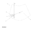
FIG. 2 a schematic representation of a windshield according to the invention, -
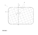
FIG. 3 a schematic representation of the sensor window according to the invention, -
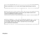
FIG. 4 a flow diagram of the manufacturing method according to the invention.
Claims (14)
Priority Applications (1)
| Application Number | Priority Date | Filing Date | Title |
|---|---|---|---|
| EP13158150.6A EP2774898A1 (en) | 2013-03-07 | 2013-03-07 | Coated pane with partially uncoated sections |
Applications Claiming Priority (1)
| Application Number | Priority Date | Filing Date | Title |
|---|---|---|---|
| EP13158150.6A EP2774898A1 (en) | 2013-03-07 | 2013-03-07 | Coated pane with partially uncoated sections |
Publications (1)
| Publication Number | Publication Date |
|---|---|
| EP2774898A1 true EP2774898A1 (en) | 2014-09-10 |
Family
ID=47843124
Family Applications (1)
| Application Number | Title | Priority Date | Filing Date |
|---|---|---|---|
| EP13158150.6A Withdrawn EP2774898A1 (en) | 2013-03-07 | 2013-03-07 | Coated pane with partially uncoated sections |
Country Status (1)
| Country | Link |
|---|---|
| EP (1) | EP2774898A1 (en) |
Cited By (4)
| Publication number | Priority date | Publication date | Assignee | Title |
|---|---|---|---|---|
| CN106587625A (en) * | 2016-12-14 | 2017-04-26 | 郑州人造金刚石及制品工程技术研究中心有限公司 | Novel ceramic glaze and preparation method and glaze application process thereof |
| CN111315699A (en) * | 2017-11-30 | 2020-06-19 | 法国圣戈班玻璃厂 | Method for producing printed, coated glass sheets |
| WO2020165167A1 (en) * | 2019-02-13 | 2020-08-20 | Agc Glass Europe | Glazing unit with frequency selective coating and method |
| CN113735460A (en) * | 2021-08-25 | 2021-12-03 | 福建省万达汽车玻璃工业有限公司 | Coated glass, method for producing same, and vehicle window |
Citations (10)
| Publication number | Priority date | Publication date | Assignee | Title |
|---|---|---|---|---|
| DE3708577A1 (en) * | 1987-03-17 | 1988-09-29 | Ver Glaswerke Gmbh | Car glass window pane which is provided with a layer which is electrically conductive and reflects heat rays |
| EP0678483B1 (en) | 1991-04-30 | 1998-12-23 | Saint-Gobain Vitrage | Glass substrate with a thin multilayer coating for solar protection |
| DE19817712C1 (en) | 1998-04-21 | 2000-02-03 | Sekurit Saint Gobain Deutsch | Transparent plate, in particular glass pane with a coating and a radiation window |
| US20020192473A1 (en) | 1999-09-23 | 2002-12-19 | Carole Gentilhomme | Glazing provided with a stack of thin layers acting on solar radiation |
| DE10314094A1 (en) * | 2002-09-17 | 2004-03-25 | Pilkington Automotive Deutschland Gmbh | Automobile antenna window panel has elongate dielectric slit between central conductive surface and metallic edge enclosing window panel |
| US6730389B2 (en) | 2001-10-25 | 2004-05-04 | Ppg Industries Ohio, Inc. | Coated substrate having a frequency selective surface |
| WO2004051869A2 (en) | 2002-12-04 | 2004-06-17 | The Ohio State University | Radio transmission region in metallic panel |
| US20070082219A1 (en) | 2003-11-28 | 2007-04-12 | Saint-Gobain Glass France | Transparent substrate which can be used alternatively or cumulatively for thermal control, electromagnetic armour and heated glazing |
| US20110146172A1 (en) | 2008-05-19 | 2011-06-23 | Saint Gobain Glass France | Glazing provided with a stack of thin layers |
| WO2012066324A1 (en) | 2010-11-19 | 2012-05-24 | Pilkington Group Limited | Method of and apparatus for manufacturing a glazing with frequency selective coating |
-
2013
- 2013-03-07 EP EP13158150.6A patent/EP2774898A1/en not_active Withdrawn
Patent Citations (10)
| Publication number | Priority date | Publication date | Assignee | Title |
|---|---|---|---|---|
| DE3708577A1 (en) * | 1987-03-17 | 1988-09-29 | Ver Glaswerke Gmbh | Car glass window pane which is provided with a layer which is electrically conductive and reflects heat rays |
| EP0678483B1 (en) | 1991-04-30 | 1998-12-23 | Saint-Gobain Vitrage | Glass substrate with a thin multilayer coating for solar protection |
| DE19817712C1 (en) | 1998-04-21 | 2000-02-03 | Sekurit Saint Gobain Deutsch | Transparent plate, in particular glass pane with a coating and a radiation window |
| US20020192473A1 (en) | 1999-09-23 | 2002-12-19 | Carole Gentilhomme | Glazing provided with a stack of thin layers acting on solar radiation |
| US6730389B2 (en) | 2001-10-25 | 2004-05-04 | Ppg Industries Ohio, Inc. | Coated substrate having a frequency selective surface |
| DE10314094A1 (en) * | 2002-09-17 | 2004-03-25 | Pilkington Automotive Deutschland Gmbh | Automobile antenna window panel has elongate dielectric slit between central conductive surface and metallic edge enclosing window panel |
| WO2004051869A2 (en) | 2002-12-04 | 2004-06-17 | The Ohio State University | Radio transmission region in metallic panel |
| US20070082219A1 (en) | 2003-11-28 | 2007-04-12 | Saint-Gobain Glass France | Transparent substrate which can be used alternatively or cumulatively for thermal control, electromagnetic armour and heated glazing |
| US20110146172A1 (en) | 2008-05-19 | 2011-06-23 | Saint Gobain Glass France | Glazing provided with a stack of thin layers |
| WO2012066324A1 (en) | 2010-11-19 | 2012-05-24 | Pilkington Group Limited | Method of and apparatus for manufacturing a glazing with frequency selective coating |
Cited By (5)
| Publication number | Priority date | Publication date | Assignee | Title |
|---|---|---|---|---|
| CN106587625A (en) * | 2016-12-14 | 2017-04-26 | 郑州人造金刚石及制品工程技术研究中心有限公司 | Novel ceramic glaze and preparation method and glaze application process thereof |
| CN111315699A (en) * | 2017-11-30 | 2020-06-19 | 法国圣戈班玻璃厂 | Method for producing printed, coated glass sheets |
| CN111315699B (en) * | 2017-11-30 | 2022-06-03 | 法国圣戈班玻璃厂 | Method for producing printed, coated glass sheets |
| WO2020165167A1 (en) * | 2019-02-13 | 2020-08-20 | Agc Glass Europe | Glazing unit with frequency selective coating and method |
| CN113735460A (en) * | 2021-08-25 | 2021-12-03 | 福建省万达汽车玻璃工业有限公司 | Coated glass, method for producing same, and vehicle window |
Similar Documents
| Publication | Publication Date | Title |
|---|---|---|
| EP2964585B1 (en) | Coated pane with partially uncoated sections | |
| EP2890655B1 (en) | Coated pane with partially uncoated sections | |
| EP3720701B1 (en) | Laminated glass pane with solar control coating and thermal radiation reflective coating | |
| EP3081378B1 (en) | Pane with high frequency transmission | |
| EP3085199B1 (en) | Heatable pane with high frequency transmission | |
| EP2380234B2 (en) | Transparent plane antenna, manufacturing method for the antenna, and use of the antenna | |
| EP2586610B1 (en) | Sheet with high frequency transmission | |
| EP3613257A1 (en) | Pane having heatable tco coating | |
| EP2774898A1 (en) | Coated pane with partially uncoated sections | |
| EP2790915B1 (en) | Radar reflection damping glazing | |
| EP4023035A1 (en) | Windowpane with pattern for high-frequency transmission | |
| EP3206999A1 (en) | Method for producing a façade element made of glass for shielding light, and light-shielding façade element | |
| DE10046810C5 (en) | Process for producing a heat-reflecting layer system for transparent substrates and layer system produced therefrom | |
| DE102018101816A1 (en) | Solar control glass and process for its preparation | |
| EP0976542A1 (en) | Laminated glass and method for making a coated plastic sheet therefor | |
| WO2023161070A1 (en) | Method for producing a curved pane which is de-coated in some regions | |
| EP4326685A1 (en) | Vehicle window with an ir-reflective coating with a discontinuous metallic layer of metal nanocrystals | |
| WO2023186406A1 (en) | Glass pane with a coating for reducing bird collisions | |
| DE202021100791U1 (en) | Disc with black print and functional coating | |
| WO2019179677A1 (en) | Laser treatment for a heatable glazing | |
| DE202017006838U1 (en) | Electrically heated window pane with a sheet-like, net-like, electrically conductive heating structure | |
| DE4344909A1 (en) | Radar de-reflection element e.g. for use at airports | |
| DE102011118850A1 (en) | Glass pane for motor car, has boundary faces having anti-reflection layer whose reflectivity for light in visible range is set to preset value and anti-fitting layer whose thermal emissivity is set to specific value, respectively |
Legal Events
| Date | Code | Title | Description |
|---|---|---|---|
| PUAI | Public reference made under article 153(3) epc to a published international application that has entered the european phase |
Free format text: ORIGINAL CODE: 0009012 |
|
| 17P | Request for examination filed |
Effective date: 20130307 |
|
| AK | Designated contracting states |
Kind code of ref document: A1 Designated state(s): AL AT BE BG CH CY CZ DE DK EE ES FI FR GB GR HR HU IE IS IT LI LT LU LV MC MK MT NL NO PL PT RO RS SE SI SK SM TR |
|
| AX | Request for extension of the european patent |
Extension state: BA ME |
|
| R17P | Request for examination filed (corrected) |
Effective date: 20150120 |
|
| RBV | Designated contracting states (corrected) |
Designated state(s): AL AT BE BG CH CY CZ DE DK EE ES FI FR GB GR HR HU IE IS IT LI LT LU LV MC MK MT NL NO PL PT RO RS SE SI SK SM TR |
|
| STAA | Information on the status of an ep patent application or granted ep patent |
Free format text: STATUS: THE APPLICATION HAS BEEN WITHDRAWN |
|
| RIC1 | Information provided on ipc code assigned before grant |
Ipc: C03C 17/36 20060101AFI20171221BHEP |
|
| 18W | Application withdrawn |
Effective date: 20180111 |