EP2775310A1 - Air data probes - Google Patents
Air data probes Download PDFInfo
- Publication number
- EP2775310A1 EP2775310A1 EP14157823.7A EP14157823A EP2775310A1 EP 2775310 A1 EP2775310 A1 EP 2775310A1 EP 14157823 A EP14157823 A EP 14157823A EP 2775310 A1 EP2775310 A1 EP 2775310A1
- Authority
- EP
- European Patent Office
- Prior art keywords
- air data
- probe
- recited
- probe head
- data probe
- Prior art date
- Legal status (The legal status is an assumption and is not a legal conclusion. Google has not performed a legal analysis and makes no representation as to the accuracy of the status listed.)
- Granted
Links
Images

Classifications
-
- G—PHYSICS
- G01—MEASURING; TESTING
- G01L—MEASURING FORCE, STRESS, TORQUE, WORK, MECHANICAL POWER, MECHANICAL EFFICIENCY, OR FLUID PRESSURE
- G01L15/00—Devices or apparatus for measuring two or more fluid pressure values simultaneously
-
- G—PHYSICS
- G01—MEASURING; TESTING
- G01P—MEASURING LINEAR OR ANGULAR SPEED, ACCELERATION, DECELERATION, OR SHOCK; INDICATING PRESENCE, ABSENCE, OR DIRECTION, OF MOVEMENT
- G01P5/00—Measuring speed of fluids, e.g. of air stream; Measuring speed of bodies relative to fluids, e.g. of ship, of aircraft
- G01P5/14—Measuring speed of fluids, e.g. of air stream; Measuring speed of bodies relative to fluids, e.g. of ship, of aircraft by measuring differences of pressure in the fluid
- G01P5/16—Measuring speed of fluids, e.g. of air stream; Measuring speed of bodies relative to fluids, e.g. of ship, of aircraft by measuring differences of pressure in the fluid using Pitot tubes, e.g. Machmeter
- G01P5/165—Arrangements or constructions of Pitot tubes
Definitions
- the present invention relates to air data probes and more particularly to air data probes for aerospace applications.
- a variety of air data probe devices are known in the art for aircraft flight control. Of such devices, many are directed to measuring Pitot pressure, static pressure, local angle of attack pressures, and angle of sideslip pressures as parameters for calculating pressure altitude, altitude rate, airspeed, Mach number, angle of attack, and angle of sideslip.
- the air data probe typically includes one or more static pressure ports located on the side of the probe head integral to the probe's surface which sense the atmospheric pressure outside of the aircraft. When these static pressure ports take consistent pressure measurements, they can provide accurate and consistent calculations of the above mentioned parameters.
- the subject of the invention is directed to an air data probe as defined in claim 1.
- the air data probe includes a probe head defining a longitudinal axis with a forward tip, and a turbulence inducing surface defined in the probe head aft of the forward tip.
- the turbulence inducing surface is configured and adapted to trip a fluid boundary layer passing over the probe head to transition from laminar to turbulent to control or reduce boundary layer separation resulting in consistent readings at high altitudes.
- the turbulence inducing surface can be defined proximate the forward tip. It is also contemplated that the air data probe can include a first static port or ports proximate the forward tip and a second static port or ports aft the first static port or ports.
- the turbulence inducing surface can be defined between the first and second static port location and can be an annular depression around the probe head.
- the turbulence inducing surface can be configured and adapted to trip a fluid boundary layer, as an example, at an altitude of approximately 45,000 feet (13,716 meters), at a speed of approximately Mach 0.9, and/or at a predetermined and/or particular angle of attack, for example of approximately 10 degrees.
- the annular depression can be defined in a lateral plane, wherein the lateral plane is perpendicular to the longitudinal axis.
- the annular depression can have a generally constant geometry around the probe head.
- the turbulence inducing surface includes a serrated surface defined in the probe head aft of the forward tip.
- the serrated surface is configured and adapted to trip a fluid boundary layer, as described above with reference to the turbulence inducing surface.
- the serrated surface can include at least one of peaks, raised features, and valleys, which together are representative of distributed roughness elements.
- the serrated surface can include serrations at opposing angles, wherein the serrations have a generally constant geometry.
- the serrated surface can be arranged circumferentially around the probe head, in a strip, and/or in opposing strips.
- the strip can also be defined along a surface of the probe head in an axial direction.
- the strip can be defined along a surface of the probe head in an axial direction 90 degrees from the static ports, circumferentially, and/or the serrated surface can extend from proximate the forward tip to an axial location proximate that of the second static port.
- FIG. 1 a partial view of an exemplary embodiment of the air data probe in accordance with the invention is shown in Fig. 1 and is designated generally by reference character 100.
- FIGs. 2-5 Other embodiments of air data probes in accordance with the invention, or aspects thereof, are provided in Figs. 2-5 as will be described.
- air data probe 100 includes a probe head 102 defining a longitudinal axis A with a forward tip 104, and a turbulence inducing surface, shown in Fig. 1 as a serrated surface 106, defined in probe head 102 aft of forward tip 104.
- Turbulence inducing surface is configured and adapted to trip a fluid boundary layer passing over probe head 102 to transition from laminar to turbulent for reducing or controlling boundary layer separation for consistent readings at low Reynolds number (Re) flight conditions, high altitudes, angle of attack and/or high Mach number.
- Re Reynolds number
- Air data probe 100 includes a first static port 108 proximate and aft of forward tip 104 and a second static port 110 aft first static port 108.
- Serrated surface 106 is configured and adapted to trip turbulence in a fluid boundary layer at low Re flight conditions, on the order of 10 5 and at a speed of approximately Mach 0.9. At angle, these conditions create a cross-flow as depicted schematically by the flow arrows in Fig. 1 .
- the serrated surface 106 trips turbulence in the boundary layer of the flow crossing it in these conditions to reduce boundary layer separation in the vicinity of static ports 108 and 110. While air data probe 100 is illustrated with only one first and second static port 108, 110, respectively, those skilled in the art will readily appreciate that additional static ports can be arranged on probe head 102 in any suitable position for a given application.
- serrated surface 106 is arranged in a single strip and includes serrations 113 at opposing angles, wherein serrations 113 have a generally constant geometry.
- the strip is defined along a surface of probe head 102 in an axial direction relative to axis A.
- serrated surface 106 is 90 degrees from static ports 108 and 110.
- Serrated surface 106 extends from proximate forward tip 104 aft to an axial position proximate that of second static port 110.
- an opposed serrated surface can be defined along a surface of probe 102 on the opposite side from serrated surface 106.
- serrated surfaces can be arranged circumferentially around probe head 102, or in any suitable position for a given application.
- serrated surface 106 includes peaks 107, raised features 109, and valleys 111, which combined are representative of distributed roughness elements, and the like.
- peaks 107 are directly representative of vortex generators which can cause diverging boundary layers to significantly increase stream wise vorticity, a known catalyst for transition from laminar to turbulent. Further, regions of the flow field that do not immediately interact with peaks 107 will follow into the crossover region of opposing cuts where raised features 109 are immediately met downstream.
- Periodic features e.g. distributed roughness elements, produced by alternating peaks 107 and valleys 111, are developed by maintaining constant parameters defining the cuts.
- a serrated surface e.g. serrated surface 106
- a ball end-mill tool is used to produce crossing cuts along the curved surface defining a probe head profile, e.g. probe head 102. Manufacturing of the serrated surface only removes material, so it does not require changing the probe head primary machining process.
- Parameters affecting the cuts include the ball end-mill diameter, cut angle, consecutive cut offset, opposing cut offset, and cut depth with respect to the probe head profile.
- the features discussed above can be analyzed and optimized for specific applications.
- the lateral width of the serrated surface and periodicity and effective height, h, shown in Fig. 3 , of peaks 107 are three parameters that can be adjusted to optimize performance.
- effective height, h is the radial distance from the base of valley 111 to adjacent peak 107, therein indicating the maximum depth valley 111 can reach with respect to the original probe head surface.
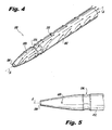
- an air data probe 200 includes turbulence inducing surface in the form of an annular depression 206 around a probe head 202.
- Annular depression 206 is defined in probe head 202, aft forward tip 204 between first and second static ports, 208 and 210, respectively.
- Annular depression 206 is configured and adapted to trip a fluid boundary layer, much as described above.
- Annular depression 206 is shown defined in a lateral plane. The lateral plane is perpendicular to longitudinal axis A, and annular depression 206 has a generally constant geometry around probe head 202.
- Annular depression 206 is configured and adapted to trip a fluid boundary layer at altitude, speed, and angle of attack conditions as described above with reference to serrated surface 106. Those skilled in the art will readily appreciate that while annular depression 206 extends all the way around the circumference of probe head 202, it is also possible to use an annular depression that extends only partially around a probe head.
- a laminar boundary layer develops along the increasing diameter of probe head 202.
- a feature e.g. annular depression 206
- an adverse pressure gradient is experienced by the laminar boundary layer, at which time it is expected to transition to a turbulent state.
- a fully developed turbulent boundary layer is formed it continues along the surface of the probe until reaching an aft static port, e.g. second static port 210.
- an aft static port e.g. second static port 210.
- annular depression e.g. annular depression 206
- annular depression 206 can be produced during a probe contour turning process.
- the annular depression only slightly modifies the standard profile, and therefore does not require major changes to the probe production methods.
- turbulence inducing surface is shown and described below as serrated surface 106 and/or an annular depression 206, those having skill in the art will readily appreciate that any suitable combinations or variations of these two types of turbulence inducing surfaces, or any other suitable type of turbulence inducing surface can be used without departing from the spirit and scope of the invention.
- annular depression 206 and serrated surface 106 do not depend on mounting hardware or adhesives, as is the case with known tape trips and vortex generators.
Landscapes
- Physics & Mathematics (AREA)
- General Physics & Mathematics (AREA)
- Engineering & Computer Science (AREA)
- Aviation & Aerospace Engineering (AREA)
- Aerodynamic Tests, Hydrodynamic Tests, Wind Tunnels, And Water Tanks (AREA)
- A Measuring Device Byusing Mechanical Method (AREA)
- Length Measuring Devices With Unspecified Measuring Means (AREA)
Abstract
Description
- The present invention relates to air data probes and more particularly to air data probes for aerospace applications.
- A variety of air data probe devices are known in the art for aircraft flight control. Of such devices, many are directed to measuring Pitot pressure, static pressure, local angle of attack pressures, and angle of sideslip pressures as parameters for calculating pressure altitude, altitude rate, airspeed, Mach number, angle of attack, and angle of sideslip. The air data probe typically includes one or more static pressure ports located on the side of the probe head integral to the probe's surface which sense the atmospheric pressure outside of the aircraft. When these static pressure ports take consistent pressure measurements, they can provide accurate and consistent calculations of the above mentioned parameters.
- During periods where an air data probe is at a high altitude, angle of attack, and/or Mach number, it is possible for the air data probe to have inconsistent measurement errors in the aft static ports. There can be considerable variations from one probe to another, suggesting there is a sensitivity to an unknown manufacturing variable at the conditions described above.
- Such conventional methods and systems generally have been considered satisfactory for their intended purpose. However, there remains an ever present need to advance the state of the art by reducing data inconsistencies in air data probes at high altitude, Mach, and/or angle of attack. There also remains a need in the art for such methods and systems that are easy to make and use. The present invention provides a solution for these problems.
- The subject of the invention is directed to an air data probe as defined in claim 1. The air data probe includes a probe head defining a longitudinal axis with a forward tip, and a turbulence inducing surface defined in the probe head aft of the forward tip. The turbulence inducing surface is configured and adapted to trip a fluid boundary layer passing over the probe head to transition from laminar to turbulent to control or reduce boundary layer separation resulting in consistent readings at high altitudes.
- In one embodiment of the subject invention, the turbulence inducing surface can be defined proximate the forward tip. It is also contemplated that the air data probe can include a first static port or ports proximate the forward tip and a second static port or ports aft the first static port or ports. The turbulence inducing surface can be defined between the first and second static port location and can be an annular depression around the probe head. The turbulence inducing surface can be configured and adapted to trip a fluid boundary layer, as an example, at an altitude of approximately 45,000 feet (13,716 meters), at a speed of approximately Mach 0.9, and/or at a predetermined and/or particular angle of attack, for example of approximately 10 degrees. The annular depression can be defined in a lateral plane, wherein the lateral plane is perpendicular to the longitudinal axis. The annular depression can have a generally constant geometry around the probe head. Those having skill in the art will readily appreciate that these features may also be beneficial at other flight conditions.
- In certain embodiments, the turbulence inducing surface includes a serrated surface defined in the probe head aft of the forward tip. The serrated surface is configured and adapted to trip a fluid boundary layer, as described above with reference to the turbulence inducing surface.
- In another aspect, the serrated surface can include at least one of peaks, raised features, and valleys, which together are representative of distributed roughness elements. The serrated surface can include serrations at opposing angles, wherein the serrations have a generally constant geometry. The serrated surface can be arranged circumferentially around the probe head, in a strip, and/or in opposing strips. The strip can also be defined along a surface of the probe head in an axial direction. The strip can be defined along a surface of the probe head in an axial direction 90 degrees from the static ports, circumferentially, and/or the serrated surface can extend from proximate the forward tip to an axial location proximate that of the second static port.
- These and other features of the systems and methods of the subject invention will become more readily apparent to those skilled in the art from the following detailed description of the embodiments taken in conjunction with the drawings.
- So that those skilled in the art to which the subject invention appertains will readily understand how to make and use the devices and methods of the subject invention without undue experimentation, embodiments thereof will be described in detail herein below by way of example only and with reference to certain figures, wherein:
-
Fig. 1 is a perspective view of an exemplary embodiment of an air data probe constructed in accordance with the present invention, showing a serrated surface and a schematic depiction of the air flow over the air data probe; -
Fig. 2 is an enlarged perspective view of a portion of the air data probe ofFig. 1 , showing the serrated surface, including serrations at opposing angles; -
Fig. 3 is an enlarged perspective view of a portion of the air data probe ofFig. 1 , showing features of the serrations, including peaks, raised features, and valleys; -
Fig. 4 is a perspective view of another exemplary embodiment of an air data probe constructed in accordance with the present invention, showing an annular depression around the probe head and a schematic depiction of the air flow over the air data probe; and -
Fig. 5 is an enlarged plan view of a portion of the air data probe ofFig. 4 , showing the annular depression and a forward static port. - Reference will now be made to the drawings wherein like reference numerals identify similar structural features or aspects of the subject invention. For purposes of explanation and illustration, and not limitation, a partial view of an exemplary embodiment of the air data probe in accordance with the invention is shown in
Fig. 1 and is designated generally byreference character 100. Other embodiments of air data probes in accordance with the invention, or aspects thereof, are provided inFigs. 2-5 as will be described. - Referring now to
Fig. 1 ,air data probe 100 includes aprobe head 102 defining a longitudinal axis A with aforward tip 104, and a turbulence inducing surface, shown inFig. 1 as aserrated surface 106, defined inprobe head 102 aft offorward tip 104. Turbulence inducing surface is configured and adapted to trip a fluid boundary layer passing overprobe head 102 to transition from laminar to turbulent for reducing or controlling boundary layer separation for consistent readings at low Reynolds number (Re) flight conditions, high altitudes, angle of attack and/or high Mach number. - With further reference to
Fig. 1 , the forward end ofserrated surface 106 is defined proximateforward tip 104.Air data probe 100 includes a firststatic port 108 proximate and aft offorward tip 104 and a secondstatic port 110 aft firststatic port 108.Serrated surface 106 is configured and adapted to trip turbulence in a fluid boundary layer at low Re flight conditions, on the order of 105 and at a speed of approximately Mach 0.9. At angle, these conditions create a cross-flow as depicted schematically by the flow arrows inFig. 1 . Theserrated surface 106 trips turbulence in the boundary layer of the flow crossing it in these conditions to reduce boundary layer separation in the vicinity ofstatic ports air data probe 100 is illustrated with only one first and secondstatic port probe head 102 in any suitable position for a given application. - With reference now to
Figs. 1 and 2 ,serrated surface 106 is arranged in a single strip and includesserrations 113 at opposing angles, whereinserrations 113 have a generally constant geometry. The strip is defined along a surface ofprobe head 102 in an axial direction relative to axis A. In the circumferential direction,serrated surface 106 is 90 degrees fromstatic ports Serrated surface 106 extends from proximateforward tip 104 aft to an axial position proximate that of secondstatic port 110. Althoughserrated surface 106, as shown inFigs. 1 and 2 , is shown as a single strip, those skilled in the art will readily appreciate that an opposed serrated surface can be defined along a surface ofprobe 102 on the opposite side fromserrated surface 106. Those skilled in the art will also readily appreciate that serrated surfaces can be arranged circumferentially aroundprobe head 102, or in any suitable position for a given application. - With reference now to
Fig. 3 ,serrated surface 106 includespeaks 107, raisedfeatures 109, andvalleys 111, which combined are representative of distributed roughness elements, and the like. Those skilled in the art will readily appreciate thatpeaks 107 are directly representative of vortex generators which can cause diverging boundary layers to significantly increase stream wise vorticity, a known catalyst for transition from laminar to turbulent. Further, regions of the flow field that do not immediately interact withpeaks 107 will follow into the crossover region of opposing cuts where raisedfeatures 109 are immediately met downstream. - Periodic features, e.g. distributed roughness elements, produced by
alternating peaks 107 andvalleys 111, are developed by maintaining constant parameters defining the cuts. Those having skill in the art will also readily appreciate that a serrated surface, e.g.serrated surface 106, can be manufactured in a secondary machining process in which a ball end-mill tool is used to produce crossing cuts along the curved surface defining a probe head profile,e.g. probe head 102. Manufacturing of the serrated surface only removes material, so it does not require changing the probe head primary machining process. - Those having skill in the art will further appreciate that cutting at large angles with respect to the probe centerline allows for a gradual increase in cut depth laterally across the probe head. The incoming boundary layer, therefore, remains fairly undisturbed until reaching protrusions, e.g. raised
features 109 formed by the initial cross cuts, orpeaks 107, formed by cross cuts with a ball end-mill at an opposing orientation, where the opposing cuts merge together. The protrusions interact with higher speed regimes of the boundary layer, something which simple surface cuts cannot accomplish. - Parameters affecting the cuts include the ball end-mill diameter, cut angle, consecutive cut offset, opposing cut offset, and cut depth with respect to the probe head profile. Those skilled in the art will readily appreciate that by systematically varying these parameters the features discussed above can be analyzed and optimized for specific applications. For example, the lateral width of the serrated surface and periodicity and effective height, h, shown in
Fig. 3 , ofpeaks 107 are three parameters that can be adjusted to optimize performance. Those skilled in the art will readily appreciate that effective height, h, is the radial distance from the base ofvalley 111 toadjacent peak 107, therein indicating themaximum depth valley 111 can reach with respect to the original probe head surface. - Referring now to
Figs. 4 and 5 , another exemplary embodiment of anair data probe 200 includes turbulence inducing surface in the form of anannular depression 206 around aprobe head 202.Annular depression 206 is defined inprobe head 202, aftforward tip 204 between first and second static ports, 208 and 210, respectively.Annular depression 206 is configured and adapted to trip a fluid boundary layer, much as described above.Annular depression 206 is shown defined in a lateral plane. The lateral plane is perpendicular to longitudinal axis A, andannular depression 206 has a generally constant geometry aroundprobe head 202.Annular depression 206 is configured and adapted to trip a fluid boundary layer at altitude, speed, and angle of attack conditions as described above with reference toserrated surface 106. Those skilled in the art will readily appreciate that whileannular depression 206 extends all the way around the circumference ofprobe head 202, it is also possible to use an annular depression that extends only partially around a probe head. - With further reference to
Figs. 4 and 5 , as air flows overprobe head 202, shown schematically from left to right inFig. 4 , a laminar boundary layer develops along the increasing diameter ofprobe head 202. Upon reaching a feature, e.g.annular depression 206, an adverse pressure gradient is experienced by the laminar boundary layer, at which time it is expected to transition to a turbulent state. Once a fully developed turbulent boundary layer is formed it continues along the surface of the probe until reaching an aft static port, e.g. secondstatic port 210. Although shown and described herein with reference to one aft static port, those skilled in the art will readily appreciate that any suitable number of aft static ports may be utilized on a probe head,e.g. probe head 202. - Those skilled in the art will readily appreciate that an annular depression, e.g.
annular depression 206, can be produced during a probe contour turning process. The annular depression only slightly modifies the standard profile, and therefore does not require major changes to the probe production methods. - Although turbulence inducing surface is shown and described below as
serrated surface 106 and/or anannular depression 206, those having skill in the art will readily appreciate that any suitable combinations or variations of these two types of turbulence inducing surfaces, or any other suitable type of turbulence inducing surface can be used without departing from the spirit and scope of the invention. In addition, those skilled in the art will readily appreciate thatannular depression 206 andserrated surface 106 do not depend on mounting hardware or adhesives, as is the case with known tape trips and vortex generators. - The methods and systems of the present invention, as described above and shown in the drawings, provide for air data probes with superior properties including reducing or controlling boundary layer separation for consistent readings at low Re conditions typically consisting of high altitudes, Mach number, and angle of attack. While the apparatus and methods of the subject invention have been shown and described with reference to certain embodiments, those skilled in the art will readily appreciate that changes and/or modifications may be made thereto without departing from the scope of the subject invention.
Claims (15)
- An air data probe (100; 200) comprising:a probe head (102; 202), the probe head defining a longitudinal axis (A) with a forward tip (104; 204); anda turbulence inducing surface (106; 206) defined in the probe head aft of the forward tip, wherein the turbulence inducing surface is configured and adapted to trip a fluid boundary layer passing over the probe head to transition from laminar to turbulent for reducing boundary layer separation for consistent readings at high altitudes.
- The air data probe (100; 200) as recited in claim 1, wherein the turbulence inducing surface (106; 206) is defined proximate the forward tip (104; 204).
- The air data probe (200) as recited in claim 1 or 2, further comprising a first static port (208) proximate the forward tip (204) and a second static port (210) aft the first static port, wherein the turbulence inducing surface is defined therebetween, and wherein the turbulence inducing surface is an annular depression (206) around the probe head (202).
- The air data probe (100) as recited in claim 1 or 2, wherein the turbulence inducing surface is a serrated surface (106), and preferably wherein the serrated surface includes at least one of peaks (107), raised features (109), and valleys (111).
- The air data probe (100) as recited in claim 4, wherein the serrated surface (106) includes serrations (113) at opposing angles, wherein the serrations have a generally constant geometry.
- The air data probe (100) as recited in claim 4 or 5, wherein the serrated surface (106) is arranged in a strip defined along a surface of the probe head in an axial direction (A).
- The air data probe (100) as recited in claim 4 or 5, wherein the serrated surface (106) is arranged in opposing strips each defined along a surface of the probe head in an axial direction (A).
- The air data probe (100) as recited in claim 4 or 5, further comprising a first static port (108) aft the forward tip (104) and a second static port (110) aft the first static port, wherein the serrated surface (106) is arranged in a strip defined along a surface of the probe head (102) in an axial direction (A) 90 degrees from the static ports.
- The air data probe (100) as recited in any of claims 4 to 7, further comprising a first static port (108) aft the forward tip (104) and a second static port (110) aft the first static port, wherein the serrated surface (106) extends from proximate the forward tip to proximate the second static port.
- The air data probe (100) as recited in claim 4 or 5, wherein the serrated surface (106) is arranged circumferentially around the probe head (102).
- The air data probe (200) as recited in claim 1 or 2, wherein the turbulence inducing surface is an annular depression (206), and preferably wherein the annular depression is defined in a lateral plane, wherein the lateral plane is perpendicular to the longitudinal axis (A).
- The air data probe (200) as recited in claim 11, wherein the annular depression (206) has a generally constant geometry around the probe head (202).
- The air data probe (100; 200) as recited in any preceding claim, wherein the turbulence inducing surface (106; 206) is configured and adapted to trip a fluid boundary layer at low Reynolds numbers on the order of 105.
- The air data probe (100; 200) as recited in any preceding claim, wherein the turbulence inducing surface (106; 206) is configured and adapted to trip a fluid boundary layer at a speed of approximately Mach 0.9.
- The air data probe (100; 200) as recited in any preceding claim, wherein the turbulence inducing surface (106; 206) is configured and adapted to trip a fluid boundary layer at a predetermined angle of attack.
Applications Claiming Priority (2)
| Application Number | Priority Date | Filing Date | Title |
|---|---|---|---|
| US201361772994P | 2013-03-05 | 2013-03-05 | |
| US14/183,665 US9341533B2 (en) | 2013-03-05 | 2014-02-19 | Air data probes |
Publications (2)
| Publication Number | Publication Date |
|---|---|
| EP2775310A1 true EP2775310A1 (en) | 2014-09-10 |
| EP2775310B1 EP2775310B1 (en) | 2017-05-03 |
Family
ID=50241124
Family Applications (1)
| Application Number | Title | Priority Date | Filing Date |
|---|---|---|---|
| EP14157823.7A Active EP2775310B1 (en) | 2013-03-05 | 2014-03-05 | Air data probes |
Country Status (4)
| Country | Link |
|---|---|
| US (1) | US9341533B2 (en) |
| EP (1) | EP2775310B1 (en) |
| BR (1) | BR102014005095B8 (en) |
| CA (1) | CA2844549C (en) |
Cited By (5)
| Publication number | Priority date | Publication date | Assignee | Title |
|---|---|---|---|---|
| EP3270169A3 (en) * | 2016-07-15 | 2018-02-14 | Rosemount Aerospace Inc. | Air data probe with turbulence-producing geometry |
| EP2947465B1 (en) * | 2014-05-20 | 2019-02-20 | Rosemount Aerospace Inc. | Air data probe with means for reducing boundary layer separation |
| US20220024602A1 (en) * | 2015-03-23 | 2022-01-27 | Rosemount Aerospace Inc. | Air data probes |
| US11624637B1 (en) | 2021-10-01 | 2023-04-11 | Rosemount Aerospace Inc | Air data probe with integrated heater bore and features |
| US11662235B2 (en) | 2021-10-01 | 2023-05-30 | Rosemount Aerospace Inc. | Air data probe with enhanced conduction integrated heater bore and features |
Families Citing this family (4)
| Publication number | Priority date | Publication date | Assignee | Title |
|---|---|---|---|---|
| US9341533B2 (en) | 2013-03-05 | 2016-05-17 | Rosemount Aerospace Inc. | Air data probes |
| RU2542791C1 (en) * | 2013-08-29 | 2015-02-27 | Федеральное государственное унитарное предприятие "Центральный аэрогидродинамический институт имени профессора Н.Е. Жуковского" (ФГУП "ЦАГИ") | Air pressure intake |
| WO2019075429A1 (en) * | 2017-10-12 | 2019-04-18 | Purdue Research Foundation | Directional probe for high temperature flows |
| FR3120941B1 (en) * | 2021-03-17 | 2023-04-07 | Thales Sa | AERONAUTICAL PROBE |
Citations (5)
| Publication number | Priority date | Publication date | Assignee | Title |
|---|---|---|---|---|
| GB1066935A (en) * | 1965-04-07 | 1967-04-26 | British Aircraft Corp Ltd | Ringed pitot static probe |
| US4378697A (en) * | 1981-07-06 | 1983-04-05 | Rosemount Inc. | Strut mounted multiple static tube |
| US5313700A (en) * | 1991-01-11 | 1994-05-24 | United Technologies Corporation | Forming a flow directing element for a turbine |
| JP2006009976A (en) * | 2004-06-28 | 2006-01-12 | Ko Yamaguchi | Fluid separation reducing device |
| EP2407671A1 (en) * | 2009-03-10 | 2012-01-18 | Daikin Industries, Ltd. | Crossflow fan and air conditioner provided with same |
Family Cites Families (14)
| Publication number | Priority date | Publication date | Assignee | Title |
|---|---|---|---|---|
| US3512414A (en) | 1968-05-23 | 1970-05-19 | Rosemount Eng Co Ltd | Slotted airfoil sensor housing |
| GB1413990A (en) | 1972-04-19 | 1975-11-12 | Secr Defence | Static pressure sensing apparatus |
| CA992348A (en) * | 1974-03-22 | 1976-07-06 | Helen G. Tucker | Measurement of at least one of the fluid flow rate and viscous characteristics using laminar flow and viscous shear |
| US5811691A (en) * | 1997-12-26 | 1998-09-22 | Sikorsky Aircraft Corporation | Blade-mounted total pressure probe for a rotating blade |
| US6315686B1 (en) | 1999-10-25 | 2001-11-13 | Gilbert Barfield | Golf ball dimple structures with vortex generators |
| FR2840984B1 (en) | 2002-06-14 | 2005-03-18 | Auxitrol Sa | IMPROVEMENTS IN SENSORS FOR MEASURING AT LEAST ONE PHYSICAL PARAMETER ON A FLUID FLOW AND PARTICULARLY IMPROVEMENTS IN SENSORS DEGIVEN FROM TOTAL AIR TEMPERATURE |
| US7379839B2 (en) | 2002-12-23 | 2008-05-27 | Rosemount Aerospace, Inc. | Multi-function air data probes employing neural networks for determining local air data parameters |
| US7128666B2 (en) | 2003-08-18 | 2006-10-31 | Callaway Golf Company | Dimples comprised of two or more intersecting surfaces |
| US7671812B1 (en) | 2008-08-15 | 2010-03-02 | Laird Technologies, Inc. | Wind noise reducing mounting bases for antenna assemblies |
| US8460779B2 (en) | 2011-03-30 | 2013-06-11 | General Electric Company | Microstructures for reducing noise of a fluid dynamic structure |
| GB2490170B (en) | 2011-04-21 | 2014-06-11 | Anakata Wind Power Resources S A R L | A horizontal axis wind turbine with diffuser |
| US9297714B2 (en) * | 2013-03-05 | 2016-03-29 | Rosemount Aerospace Inc. | Air data probes |
| US9341533B2 (en) | 2013-03-05 | 2016-05-17 | Rosemount Aerospace Inc. | Air data probes |
| US9981756B2 (en) | 2013-10-15 | 2018-05-29 | Rosemount Aerospace Inc. | Total air temperature sensors |
-
2014
- 2014-02-19 US US14/183,665 patent/US9341533B2/en active Active
- 2014-03-03 CA CA2844549A patent/CA2844549C/en active Active
- 2014-03-05 BR BR102014005095A patent/BR102014005095B8/en active IP Right Grant
- 2014-03-05 EP EP14157823.7A patent/EP2775310B1/en active Active
Patent Citations (5)
| Publication number | Priority date | Publication date | Assignee | Title |
|---|---|---|---|---|
| GB1066935A (en) * | 1965-04-07 | 1967-04-26 | British Aircraft Corp Ltd | Ringed pitot static probe |
| US4378697A (en) * | 1981-07-06 | 1983-04-05 | Rosemount Inc. | Strut mounted multiple static tube |
| US5313700A (en) * | 1991-01-11 | 1994-05-24 | United Technologies Corporation | Forming a flow directing element for a turbine |
| JP2006009976A (en) * | 2004-06-28 | 2006-01-12 | Ko Yamaguchi | Fluid separation reducing device |
| EP2407671A1 (en) * | 2009-03-10 | 2012-01-18 | Daikin Industries, Ltd. | Crossflow fan and air conditioner provided with same |
Cited By (7)
| Publication number | Priority date | Publication date | Assignee | Title |
|---|---|---|---|---|
| EP2947465B1 (en) * | 2014-05-20 | 2019-02-20 | Rosemount Aerospace Inc. | Air data probe with means for reducing boundary layer separation |
| US20220024602A1 (en) * | 2015-03-23 | 2022-01-27 | Rosemount Aerospace Inc. | Air data probes |
| US11731782B2 (en) * | 2015-03-23 | 2023-08-22 | Rosemount Aerospace Inc. | Bulkheads for air data probes |
| EP3270169A3 (en) * | 2016-07-15 | 2018-02-14 | Rosemount Aerospace Inc. | Air data probe with turbulence-producing geometry |
| US10416188B2 (en) | 2016-07-15 | 2019-09-17 | Rosemount Aerospace Inc. | Air data probe with turbulence-producing geometry |
| US11624637B1 (en) | 2021-10-01 | 2023-04-11 | Rosemount Aerospace Inc | Air data probe with integrated heater bore and features |
| US11662235B2 (en) | 2021-10-01 | 2023-05-30 | Rosemount Aerospace Inc. | Air data probe with enhanced conduction integrated heater bore and features |
Also Published As
| Publication number | Publication date |
|---|---|
| US20140251000A1 (en) | 2014-09-11 |
| BR102014005095A2 (en) | 2019-12-10 |
| EP2775310B1 (en) | 2017-05-03 |
| BR102014005095B1 (en) | 2022-01-25 |
| CA2844549A1 (en) | 2014-09-05 |
| US9341533B2 (en) | 2016-05-17 |
| CA2844549C (en) | 2022-06-21 |
| BR102014005095B8 (en) | 2022-02-08 |
Similar Documents
| Publication | Publication Date | Title |
|---|---|---|
| US9341533B2 (en) | Air data probes | |
| EP2700952B1 (en) | Moisture resistant air data probes | |
| EP2848904B1 (en) | Supercritical total air temperature sensors | |
| US10611499B2 (en) | Total air temperature sensors | |
| US6490510B1 (en) | Fixed multifunction probe for aircraft | |
| US9297714B2 (en) | Air data probes | |
| EP3575803A2 (en) | Air data probe with improved performance at angle of attack operation | |
| EP2947465B1 (en) | Air data probe with means for reducing boundary layer separation | |
| CN111498141B (en) | Method and device for realizing real-time monitoring of airflow angle based on micro probe | |
| CN111487031B (en) | Device and method for realizing real-time monitoring of three-dimensional flow field airflow angle based on miniature fan-shaped probe | |
| EP3179253B1 (en) | Air data probe with elliptical cross section | |
| WO2020141316A1 (en) | Improvements in or relating to angle of attack sensing | |
| CN104833443B (en) | Total air temperature sensor |
Legal Events
| Date | Code | Title | Description |
|---|---|---|---|
| PUAI | Public reference made under article 153(3) epc to a published international application that has entered the european phase |
Free format text: ORIGINAL CODE: 0009012 |
|
| 17P | Request for examination filed |
Effective date: 20140305 |
|
| AK | Designated contracting states |
Kind code of ref document: A1 Designated state(s): AL AT BE BG CH CY CZ DE DK EE ES FI FR GB GR HR HU IE IS IT LI LT LU LV MC MK MT NL NO PL PT RO RS SE SI SK SM TR |
|
| AX | Request for extension of the european patent |
Extension state: BA ME |
|
| R17P | Request for examination filed (corrected) |
Effective date: 20150309 |
|
| RBV | Designated contracting states (corrected) |
Designated state(s): AL AT BE BG CH CY CZ DE DK EE ES FI FR GB GR HR HU IE IS IT LI LT LU LV MC MK MT NL NO PL PT RO RS SE SI SK SM TR |
|
| 17Q | First examination report despatched |
Effective date: 20151022 |
|
| REG | Reference to a national code |
Ref country code: DE Ref legal event code: R079 Ref document number: 602014009176 Country of ref document: DE Free format text: PREVIOUS MAIN CLASS: G01P0015160000 Ipc: G01P0005165000 |
|
| GRAP | Despatch of communication of intention to grant a patent |
Free format text: ORIGINAL CODE: EPIDOSNIGR1 |
|
| RIC1 | Information provided on ipc code assigned before grant |
Ipc: G01L 15/00 20060101ALI20160825BHEP Ipc: G01P 5/165 20060101AFI20160825BHEP |
|
| INTG | Intention to grant announced |
Effective date: 20160913 |
|
| GRAS | Grant fee paid |
Free format text: ORIGINAL CODE: EPIDOSNIGR3 |
|
| GRAA | (expected) grant |
Free format text: ORIGINAL CODE: 0009210 |
|
| AK | Designated contracting states |
Kind code of ref document: B1 Designated state(s): AL AT BE BG CH CY CZ DE DK EE ES FI FR GB GR HR HU IE IS IT LI LT LU LV MC MK MT NL NO PL PT RO RS SE SI SK SM TR |
|
| REG | Reference to a national code |
Ref country code: GB Ref legal event code: FG4D |
|
| REG | Reference to a national code |
Ref country code: AT Ref legal event code: REF Ref document number: 890577 Country of ref document: AT Kind code of ref document: T Effective date: 20170515 Ref country code: CH Ref legal event code: EP |
|
| REG | Reference to a national code |
Ref country code: IE Ref legal event code: FG4D |
|
| REG | Reference to a national code |
Ref country code: DE Ref legal event code: R096 Ref document number: 602014009176 Country of ref document: DE |
|
| REG | Reference to a national code |
Ref country code: NL Ref legal event code: MP Effective date: 20170503 |
|
| REG | Reference to a national code |
Ref country code: AT Ref legal event code: MK05 Ref document number: 890577 Country of ref document: AT Kind code of ref document: T Effective date: 20170503 |
|
| REG | Reference to a national code |
Ref country code: LT Ref legal event code: MG4D |
|
| PG25 | Lapsed in a contracting state [announced via postgrant information from national office to epo] |
Ref country code: GR Free format text: LAPSE BECAUSE OF FAILURE TO SUBMIT A TRANSLATION OF THE DESCRIPTION OR TO PAY THE FEE WITHIN THE PRESCRIBED TIME-LIMIT Effective date: 20170804 Ref country code: ES Free format text: LAPSE BECAUSE OF FAILURE TO SUBMIT A TRANSLATION OF THE DESCRIPTION OR TO PAY THE FEE WITHIN THE PRESCRIBED TIME-LIMIT Effective date: 20170503 Ref country code: FI Free format text: LAPSE BECAUSE OF FAILURE TO SUBMIT A TRANSLATION OF THE DESCRIPTION OR TO PAY THE FEE WITHIN THE PRESCRIBED TIME-LIMIT Effective date: 20170503 Ref country code: NO Free format text: LAPSE BECAUSE OF FAILURE TO SUBMIT A TRANSLATION OF THE DESCRIPTION OR TO PAY THE FEE WITHIN THE PRESCRIBED TIME-LIMIT Effective date: 20170803 Ref country code: HR Free format text: LAPSE BECAUSE OF FAILURE TO SUBMIT A TRANSLATION OF THE DESCRIPTION OR TO PAY THE FEE WITHIN THE PRESCRIBED TIME-LIMIT Effective date: 20170503 Ref country code: AT Free format text: LAPSE BECAUSE OF FAILURE TO SUBMIT A TRANSLATION OF THE DESCRIPTION OR TO PAY THE FEE WITHIN THE PRESCRIBED TIME-LIMIT Effective date: 20170503 Ref country code: LT Free format text: LAPSE BECAUSE OF FAILURE TO SUBMIT A TRANSLATION OF THE DESCRIPTION OR TO PAY THE FEE WITHIN THE PRESCRIBED TIME-LIMIT Effective date: 20170503 |
|
| PG25 | Lapsed in a contracting state [announced via postgrant information from national office to epo] |
Ref country code: BG Free format text: LAPSE BECAUSE OF FAILURE TO SUBMIT A TRANSLATION OF THE DESCRIPTION OR TO PAY THE FEE WITHIN THE PRESCRIBED TIME-LIMIT Effective date: 20170803 Ref country code: IS Free format text: LAPSE BECAUSE OF FAILURE TO SUBMIT A TRANSLATION OF THE DESCRIPTION OR TO PAY THE FEE WITHIN THE PRESCRIBED TIME-LIMIT Effective date: 20170903 Ref country code: PL Free format text: LAPSE BECAUSE OF FAILURE TO SUBMIT A TRANSLATION OF THE DESCRIPTION OR TO PAY THE FEE WITHIN THE PRESCRIBED TIME-LIMIT Effective date: 20170503 Ref country code: LV Free format text: LAPSE BECAUSE OF FAILURE TO SUBMIT A TRANSLATION OF THE DESCRIPTION OR TO PAY THE FEE WITHIN THE PRESCRIBED TIME-LIMIT Effective date: 20170503 Ref country code: RS Free format text: LAPSE BECAUSE OF FAILURE TO SUBMIT A TRANSLATION OF THE DESCRIPTION OR TO PAY THE FEE WITHIN THE PRESCRIBED TIME-LIMIT Effective date: 20170503 Ref country code: SE Free format text: LAPSE BECAUSE OF FAILURE TO SUBMIT A TRANSLATION OF THE DESCRIPTION OR TO PAY THE FEE WITHIN THE PRESCRIBED TIME-LIMIT Effective date: 20170503 Ref country code: NL Free format text: LAPSE BECAUSE OF FAILURE TO SUBMIT A TRANSLATION OF THE DESCRIPTION OR TO PAY THE FEE WITHIN THE PRESCRIBED TIME-LIMIT Effective date: 20170503 |
|
| PG25 | Lapsed in a contracting state [announced via postgrant information from national office to epo] |
Ref country code: EE Free format text: LAPSE BECAUSE OF FAILURE TO SUBMIT A TRANSLATION OF THE DESCRIPTION OR TO PAY THE FEE WITHIN THE PRESCRIBED TIME-LIMIT Effective date: 20170503 Ref country code: RO Free format text: LAPSE BECAUSE OF FAILURE TO SUBMIT A TRANSLATION OF THE DESCRIPTION OR TO PAY THE FEE WITHIN THE PRESCRIBED TIME-LIMIT Effective date: 20170503 Ref country code: CZ Free format text: LAPSE BECAUSE OF FAILURE TO SUBMIT A TRANSLATION OF THE DESCRIPTION OR TO PAY THE FEE WITHIN THE PRESCRIBED TIME-LIMIT Effective date: 20170503 Ref country code: SK Free format text: LAPSE BECAUSE OF FAILURE TO SUBMIT A TRANSLATION OF THE DESCRIPTION OR TO PAY THE FEE WITHIN THE PRESCRIBED TIME-LIMIT Effective date: 20170503 Ref country code: DK Free format text: LAPSE BECAUSE OF FAILURE TO SUBMIT A TRANSLATION OF THE DESCRIPTION OR TO PAY THE FEE WITHIN THE PRESCRIBED TIME-LIMIT Effective date: 20170503 |
|
| REG | Reference to a national code |
Ref country code: DE Ref legal event code: R097 Ref document number: 602014009176 Country of ref document: DE |
|
| REG | Reference to a national code |
Ref country code: FR Ref legal event code: PLFP Year of fee payment: 5 |
|
| PG25 | Lapsed in a contracting state [announced via postgrant information from national office to epo] |
Ref country code: IT Free format text: LAPSE BECAUSE OF FAILURE TO SUBMIT A TRANSLATION OF THE DESCRIPTION OR TO PAY THE FEE WITHIN THE PRESCRIBED TIME-LIMIT Effective date: 20170503 Ref country code: SM Free format text: LAPSE BECAUSE OF FAILURE TO SUBMIT A TRANSLATION OF THE DESCRIPTION OR TO PAY THE FEE WITHIN THE PRESCRIBED TIME-LIMIT Effective date: 20170503 |
|
| PLBE | No opposition filed within time limit |
Free format text: ORIGINAL CODE: 0009261 |
|
| STAA | Information on the status of an ep patent application or granted ep patent |
Free format text: STATUS: NO OPPOSITION FILED WITHIN TIME LIMIT |
|
| 26N | No opposition filed |
Effective date: 20180206 |
|
| PG25 | Lapsed in a contracting state [announced via postgrant information from national office to epo] |
Ref country code: SI Free format text: LAPSE BECAUSE OF FAILURE TO SUBMIT A TRANSLATION OF THE DESCRIPTION OR TO PAY THE FEE WITHIN THE PRESCRIBED TIME-LIMIT Effective date: 20170503 |
|
| REG | Reference to a national code |
Ref country code: CH Ref legal event code: PL |
|
| PG25 | Lapsed in a contracting state [announced via postgrant information from national office to epo] |
Ref country code: MC Free format text: LAPSE BECAUSE OF FAILURE TO SUBMIT A TRANSLATION OF THE DESCRIPTION OR TO PAY THE FEE WITHIN THE PRESCRIBED TIME-LIMIT Effective date: 20170503 |
|
| REG | Reference to a national code |
Ref country code: BE Ref legal event code: MM Effective date: 20180331 |
|
| REG | Reference to a national code |
Ref country code: IE Ref legal event code: MM4A |
|
| PG25 | Lapsed in a contracting state [announced via postgrant information from national office to epo] |
Ref country code: LU Free format text: LAPSE BECAUSE OF NON-PAYMENT OF DUE FEES Effective date: 20180305 |
|
| PG25 | Lapsed in a contracting state [announced via postgrant information from national office to epo] |
Ref country code: IE Free format text: LAPSE BECAUSE OF NON-PAYMENT OF DUE FEES Effective date: 20180305 |
|
| PG25 | Lapsed in a contracting state [announced via postgrant information from national office to epo] |
Ref country code: CH Free format text: LAPSE BECAUSE OF NON-PAYMENT OF DUE FEES Effective date: 20180331 Ref country code: LI Free format text: LAPSE BECAUSE OF NON-PAYMENT OF DUE FEES Effective date: 20180331 Ref country code: BE Free format text: LAPSE BECAUSE OF NON-PAYMENT OF DUE FEES Effective date: 20180331 |
|
| PG25 | Lapsed in a contracting state [announced via postgrant information from national office to epo] |
Ref country code: MT Free format text: LAPSE BECAUSE OF NON-PAYMENT OF DUE FEES Effective date: 20180305 |
|
| PG25 | Lapsed in a contracting state [announced via postgrant information from national office to epo] |
Ref country code: TR Free format text: LAPSE BECAUSE OF FAILURE TO SUBMIT A TRANSLATION OF THE DESCRIPTION OR TO PAY THE FEE WITHIN THE PRESCRIBED TIME-LIMIT Effective date: 20170503 |
|
| PG25 | Lapsed in a contracting state [announced via postgrant information from national office to epo] |
Ref country code: PT Free format text: LAPSE BECAUSE OF FAILURE TO SUBMIT A TRANSLATION OF THE DESCRIPTION OR TO PAY THE FEE WITHIN THE PRESCRIBED TIME-LIMIT Effective date: 20170503 Ref country code: HU Free format text: LAPSE BECAUSE OF FAILURE TO SUBMIT A TRANSLATION OF THE DESCRIPTION OR TO PAY THE FEE WITHIN THE PRESCRIBED TIME-LIMIT; INVALID AB INITIO Effective date: 20140305 |
|
| PG25 | Lapsed in a contracting state [announced via postgrant information from national office to epo] |
Ref country code: MK Free format text: LAPSE BECAUSE OF NON-PAYMENT OF DUE FEES Effective date: 20170503 Ref country code: CY Free format text: LAPSE BECAUSE OF FAILURE TO SUBMIT A TRANSLATION OF THE DESCRIPTION OR TO PAY THE FEE WITHIN THE PRESCRIBED TIME-LIMIT Effective date: 20170503 |
|
| PG25 | Lapsed in a contracting state [announced via postgrant information from national office to epo] |
Ref country code: AL Free format text: LAPSE BECAUSE OF FAILURE TO SUBMIT A TRANSLATION OF THE DESCRIPTION OR TO PAY THE FEE WITHIN THE PRESCRIBED TIME-LIMIT Effective date: 20170503 |
|
| REG | Reference to a national code |
Ref country code: DE Ref legal event code: R082 Ref document number: 602014009176 Country of ref document: DE |
|
| PGFP | Annual fee paid to national office [announced via postgrant information from national office to epo] |
Ref country code: FR Payment date: 20230222 Year of fee payment: 10 |
|
| PGFP | Annual fee paid to national office [announced via postgrant information from national office to epo] |
Ref country code: GB Payment date: 20230222 Year of fee payment: 10 Ref country code: DE Payment date: 20230221 Year of fee payment: 10 |