EP2775378A1 - Stylus and optical touch panel device - Google Patents
Stylus and optical touch panel device Download PDFInfo
- Publication number
- EP2775378A1 EP2775378A1 EP14155666.2A EP14155666A EP2775378A1 EP 2775378 A1 EP2775378 A1 EP 2775378A1 EP 14155666 A EP14155666 A EP 14155666A EP 2775378 A1 EP2775378 A1 EP 2775378A1
- Authority
- EP
- European Patent Office
- Prior art keywords
- light
- touch panel
- stylus
- light emitting
- shielding member
- Prior art date
- Legal status (The legal status is an assumption and is not a legal conclusion. Google has not performed a legal analysis and makes no representation as to the accuracy of the status listed.)
- Withdrawn
Links
Images


Classifications
-
- G—PHYSICS
- G06—COMPUTING; CALCULATING OR COUNTING
- G06F—ELECTRIC DIGITAL DATA PROCESSING
- G06F3/00—Input arrangements for transferring data to be processed into a form capable of being handled by the computer; Output arrangements for transferring data from processing unit to output unit, e.g. interface arrangements
- G06F3/01—Input arrangements or combined input and output arrangements for interaction between user and computer
- G06F3/03—Arrangements for converting the position or the displacement of a member into a coded form
- G06F3/033—Pointing devices displaced or positioned by the user, e.g. mice, trackballs, pens or joysticks; Accessories therefor
- G06F3/0354—Pointing devices displaced or positioned by the user, e.g. mice, trackballs, pens or joysticks; Accessories therefor with detection of 2D relative movements between the device, or an operating part thereof, and a plane or surface, e.g. 2D mice, trackballs, pens or pucks
- G06F3/03545—Pens or stylus
-
- G—PHYSICS
- G06—COMPUTING; CALCULATING OR COUNTING
- G06F—ELECTRIC DIGITAL DATA PROCESSING
- G06F3/00—Input arrangements for transferring data to be processed into a form capable of being handled by the computer; Output arrangements for transferring data from processing unit to output unit, e.g. interface arrangements
- G06F3/01—Input arrangements or combined input and output arrangements for interaction between user and computer
- G06F3/03—Arrangements for converting the position or the displacement of a member into a coded form
- G06F3/0304—Detection arrangements using opto-electronic means
- G06F3/0325—Detection arrangements using opto-electronic means using a plurality of light emitters or reflectors or a plurality of detectors forming a reference frame from which to derive the orientation of the object, e.g. by triangulation or on the basis of reference deformation in the picked up image
-
- G—PHYSICS
- G06—COMPUTING; CALCULATING OR COUNTING
- G06F—ELECTRIC DIGITAL DATA PROCESSING
- G06F3/00—Input arrangements for transferring data to be processed into a form capable of being handled by the computer; Output arrangements for transferring data from processing unit to output unit, e.g. interface arrangements
- G06F3/01—Input arrangements or combined input and output arrangements for interaction between user and computer
- G06F3/03—Arrangements for converting the position or the displacement of a member into a coded form
- G06F3/041—Digitisers, e.g. for touch screens or touch pads, characterised by the transducing means
- G06F3/042—Digitisers, e.g. for touch screens or touch pads, characterised by the transducing means by opto-electronic means
- G06F3/0421—Digitisers, e.g. for touch screens or touch pads, characterised by the transducing means by opto-electronic means by interrupting or reflecting a light beam, e.g. optical touch-screen
-
- G—PHYSICS
- G06—COMPUTING; CALCULATING OR COUNTING
- G06F—ELECTRIC DIGITAL DATA PROCESSING
- G06F3/00—Input arrangements for transferring data to be processed into a form capable of being handled by the computer; Output arrangements for transferring data from processing unit to output unit, e.g. interface arrangements
- G06F3/01—Input arrangements or combined input and output arrangements for interaction between user and computer
- G06F3/03—Arrangements for converting the position or the displacement of a member into a coded form
- G06F3/041—Digitisers, e.g. for touch screens or touch pads, characterised by the transducing means
- G06F3/042—Digitisers, e.g. for touch screens or touch pads, characterised by the transducing means by opto-electronic means
- G06F3/0428—Digitisers, e.g. for touch screens or touch pads, characterised by the transducing means by opto-electronic means by sensing at the edges of the touch surface the interruption of optical paths, e.g. an illumination plane, parallel to the touch surface which may be virtual
Definitions
- the present invention relates to a stylus and an optical touch panel device.
- a conventional technology is disclosed (for example, see Japanese Patent No. 4627781 ) in which two light emitting/receiving units each emit light along a touch panel on which a desired position is pointed by using a stylus, the positional information is detected on the shadow (light blocked image) that occurs when the light is blocked by the end of the stylus, and the positional information on the above-described desired position is determined on the basis of the above positional information.
- a stylus that includes an end having a surface, an arbitrary area of which is to be moved close to or brought into contact with a desired position on a touch panel of an optical touch panel device.
- the end includes a light shielding member configured to block at least part of incident light.
- the stylus extends along an axis line that passes through a center of gravity of the light shielding member. A distance between a predetermined part of the light shielding member on the axis line and the arbitrary area is constant.
- an optical touch panel device that includes the stylus according to the above embodiment; the touch panel which has a rectangular plate shape and on which the desired position is pointed by using the stylus; a pair of light emitting/receiving devices each configured to include a light emitting unit and a light receiving unit, the light emitting/receiving devices being separately provided on two ends of the touch panel; a retroreflective member configured to reflect incident light into a direction opposite to an incident direction, the retroreflective member being provided along an outer edge of the touch panel; optical systems provided for the light emitting/receiving devices, respectively, each optical system being configured to guide light emitted from the light emitting unit of the corresponding light emitting/receiving device into the retroreflective member so that the light travels along the touch panel, and guide the light reflected by the retroreflective member into the light receiving unit of the corresponding light emitting/receiving device; and a positional-information calculation unit configured to, in response to pointing the desired position
- FIG. 1 illustrates a schematic configuration of an optical touch panel device 100 according to an embodiment.
- the optical touch panel device 100 includes, for example, a stylus pen 10, a touch panel 12 (not illustrated in FIG. 1 , see FIG. 2 ), a touch-panel control unit 14, a personal computer (PC) unit 16, or the like.
- the optical touch panel device 100 serves as what is called an electronic blackboard.
- the stylus pen 10 is a pointing device that is used for pointing a desired position on the touch panel 12.
- the stylus pen 10 will be explained in detail later.
- the touch panel 12 is shaped like a rectangular plate.
- an explanation is given by using an XYZ three-dimensional orthogonal coordinate system where the longitudinal direction of the touch panel 12 is the direction of an axis X, the lateral direction thereof is the direction of an axis Y, and the direction (the thickness direction of the touch panel 12) perpendicular to the direction of the axis X and the direction of the axis Y is the direction of an axis Z.
- a first light emitting/receiving unit 20a is provided on the end of the touch panel 12 on, for example, the -X and +Y side thereof, and a second light emitting/receiving unit 20b is provided on the end of the touch panel 12 on, for example, the +X and +Y side.
- the first and second light emitting/receiving units 20a and 20b have substantially the same configuration and function.
- Each of the light emitting/receiving units includes a light receiving/emitting device that includes a light emitting unit 83 and a light receiving unit 50.
- Retroreflective members 24 are provided on the edges of the touch panel 12 on the +X side, -X side, and -Y side. Each of the retroreflective members 24 has characteristics such that it reflects an incident light in the direction opposite (the direction reverse) to the incident direction regardless of the incident angle.
- the touch-panel control unit 14 includes a positional-information calculation unit 14a that calculates the positional information (XY coordinates) on a desired position that is on the touch panel 12 and that is pointed by using the stylus pen 10; and a control unit 14b that outputs the positional information to the PC unit 16 as appropriate.
- the positional-information calculation unit 14a will be explained in detail later.
- the PC unit 16 includes a signal input unit 16a that inputs the positional information from the control unit 14b; a signal processing unit 16b that processes a signal from the signal input unit 16a; an operating system (OS) 16c that outputs the processing details on the basis of the signal that is processed by the signal processing unit 16b; and an application 16d that uses the processing details from the OS 16c.
- OS operating system
- a desired position (a pointed position P) on the touch panel 12 of the optical touch panel device 100 is pressed and pointed by using a pointing unit 2, such as a user's finger, pen, or pointer, which includes an optically opaque component.
- the positional information (XY coordinates) on the pointed position is detected so that the application 16d can be finally executed.
- the first light emitting/receiving unit 20a emits the flux of multiple light beams L1, L2, L3, ..., and Ln (probe light) along the touch panel 12.
- the probe light is a light wave that travels from the first light emitting/receiving unit 20a and expands in a fan-like form along the touch panel 12.
- the second light emitting/receiving unit 20b emits the flux of multiple light beams (probe light) along the touch panel 12.
- One of the fan-like light waves from the first light emitting/receiving unit 20a i.e., the light beam Lm is reflected by the retroreflective member 24 on the -Y side, and a retroreflected light Lm' returns to the first light emitting/receiving unit 20a through the same optical path as the light beam Lm.
- the light beam Lk When a user touches the pointed position P on the touch panel 12 with, for example, his/her finger, the light beam Lk is blocked by the finger at the pointed position P and does not reach the retroreflective member 24. In this case, as the retroreflected light of the light beam Lk is not received by the first light emitting/receiving unit 20a, it can be determined that a light shielding object exists on the optical path (on a straight line L) of the light beam Lk.
- the retroreflected light of the light beam Lj emitted by the second light emitting/receiving unit 20b is not received by the second light emitting/receiving unit 20b, it can be determined that a light shielding object exists on the optical path (on a straight line R) of the light beam Lj.
- the straight line L and the straight line R are determined, and the coordinates of the intersection point of the straight lines are calculated, whereby it is possible to determine the XY coordinates of the pointed position P on the touch panel 12.
- FIG. 3 schematically illustrates the configuration of the first light emitting/receiving unit 20a.
- the first light emitting/receiving unit 20a includes, in addition to the above-described light receiving/emitting device, an optical system 90 that includes a point light source 81 and a condensing lens 51, or the like.
- an optical system 90 that includes a point light source 81 and a condensing lens 51, or the like.
- the direction of the optical axis of the condensing lens 51 is the direction of an axis x
- the direction perpendicular to the direction of the axis x on a plane parallel to the touch panel 12 is the direction of an axis y
- the direction perpendicular to the direction of the axis x and the direction of the axis y is the direction of an axis z.
- the direction of the axis z is parallel to the direction of the axis Z.
- the point light source 81 is provided on the +x side of the light receiving unit 50 and in the vicinity of the center of the condensing lens 51 so as to emit, to the +x side, fan-like light that is parallel to the xy plane.
- the light receiving unit 50 is provided in the vicinity of the focus position of the condensing lens 51 such that the light receiving surface of the light receiving unit 50 is perpendicular to the axis x.
- the fan-like light that is emitted by the point light source 81 is the flux of light beams that travel in the direction of the arrow ⁇ , in the direction of the arrow ⁇ , and in the other directions.
- the light beam that travels in the direction of the arrow ⁇ is reflected by the retroreflective member 24, is condensed by the condensing lens 51, and then reaches a light received position p1 on the light receiving unit 50. Furthermore, the light beam that travels in the direction of the arrow ⁇ is reflected by the retroreflective member 24, is condensed by the condensing lens 51, and then reaches a light received position p2 on the light receiving unit 50.
- the examination on the light intensity distribution on the light receiving unit 50 makes it possible to determine which one of the beams is blocked.
- the light is reflected by the retroreflective member 24, and is returned to the point light source 81 through the same optical path.
- the retroreflected light passes through the center of the condensing lens 51 and travels to the -x side of the condensing lens 51 (the side of the light receiving unit 50) through the optical path that is point-symmetric with respect to the center of the condensing lens 51.
- the pointing unit 2 is not in contact with or is not located close to the touch panel 12, the light intensity distribution on the entire area of the light receiving unit 50 is nearly constant.
- the beam that travels from the first light emitting/receiving unit 20a toward the pointed position P is blocked, whereby a low light-intensity area (dark point) is generated on a position D n of the light receiving unit 50.
- the position D n corresponds to the outgoing/incoming angle ⁇ n of the blocked beam, and ⁇ n can be determined by detecting D n . That is, ⁇ n can be represented by using the following Equation (1) as a function of D n .
- ⁇ n arctan D n / f
- D n is equivalent to the y-coordinate of a light received position p n , where the origin thereof is the intersection point between the light receiving surface of the light receiving unit 50 and the straight line that is parallel to the axis x that passes through the center of the condensing lens 51.
- Equation (2) a function of D nL that is determined by using the above-described Equation (1).
- the first light emitting/receiving unit 20a is installed in the coordinate input area with an interval W as illustrated in FIG. 5 , and the coordinates (X, Y) of the pointed position P on the coordinate input area are represented by using the following Equations (4) and (5).
- X wtan ⁇ R / tan ⁇ L + tan ⁇
- R Y wtan ⁇ L ⁇ tan ⁇ R / tan ⁇ L + tan ⁇ R
- X and Y can be represented as the functions of D nL and D nR .
- the positions D nL and D nR of the dark points on the light receiving units 50 in the first and second light emitting/receiving units 20a and 20b are detected, and the geometric arrangement of each of the light emitting/receiving units is considered, whereby it is possible to detect the coordinates of the pointed position P that is pointed by using the pointing unit 2.
- FIG. 6 illustrates a state where a single light emitting/receiving unit is provided on the touch panel 12.
- a light source that is used as the light emitting unit 83 is, for example, a laser diode or pinpoint LED, capable of emitting light having a certain degree of directivity.
- the light emitting unit 83 emits light in the -Z direction.
- a photo diode or photo transistor is used as the light receiving unit 50.
- the optical system 90 includes, in addition to the above-described condensing lens 51, a cylindrical lens group that includes three cylindrical lenses 84, 85, and 86 that are provided on the optical path of light from the light emitting unit 83; a slit plate 82 that is provided on the optical path of light that passes through the cylindrical lens group; a half mirror 87 that is provided on the optical path of light that passes through the slit plate 82; or the like.
- a section Q in FIG. 6 is a diagram of the light emitting unit 83, the cylindrical lens group, and the slit plate 82 when viewed from the +X side. Due to the effect of the cylindrical lens group, the light is shaped in the form of a line that extends in the direction of the axis X in cross-section and is emitted to the -Z side of the cylindrical lens 86.
- the light from the cylindrical lens 86 is incident on the slit plate 82 on which an elongated slit is formed and extends in the direction of the axis X, whereby the point light source 81 is formed as a secondary light source.
- the point light source 81 is also referred to as the secondary light source 81 for convenience.
- the secondary light source 81 is formed at the position of the slit of the slit plate 82 so as to emit linear light that extends in the direction of the axis X in cross-section.
- the light from the secondary light source 81 is reflected by the half mirror 87 to the +X side so as to travel along the touch panel 12 as a parallel light that does not expand in the direction of the axis Z but, in a direction parallel to the touch panel 12, expands in a fan-like form with the secondary light source 81 at the center.
- the traveling light is reflected by the retroreflective member 24 that is provided on the outer edge of the touch panel 12 and is returned to the side of the half mirror 87 (in the direction of the arrow C in FIG. 6 ) through the same path.
- the light After transmitting through the half mirror 87, the light travels in parallel to the touch panel 12, passes through the condensing lens 51, and is incident on the light receiving unit 50.
- the secondary light source 81 and the condensing lens 51 have a conjugated positional relationship with respect to the half mirror 87 (see the arrow D in FIG. 6 ). Furthermore, a section V in FIG. 6 is a diagram of the light receiving unit 50 and the condensing lens 51 when viewed in the +Z direction.
- the above-described optical system 90 may be changed as appropriate.
- the positional-information calculation unit 14a calculates the positional information (XY coordinates) of the pointed position P by using the principle of triangulation and by using a light received signal from the light receiving unit of each of the light emitting/receiving units that are provided in the above-described optical touch panel device 100, and then outputs it to the signal input unit 16a via the control unit 14b at a predetermined rate.
- the coordinate value of the pointed position P and a light blocked signal are output from the positional-information calculation unit 14a at a predetermined rate and are input to the signal processing unit 16b (driver) via the signal input unit 16a.
- the coordinate value of the pointed position P is a valid value when the light blocked signal is true and, it is an invalid value when the light blocked signal is false.
- the stylus pen 10 extends along a predetermined axis line.
- the stylus pen 10 includes, for example, a grip section 102 that is constituted by a substantially cylindrical and elongated member that extends in the direction of the above-described axis line; a movable pen tip 104 that is attached to the grip section 102; and a pressure detection unit 105.
- the movable pen tip 104 is constituted by a member that extends in the direction of the above-described axis line and includes an end 104a that is constituted by a spherical light shielding member.
- the above-described axis line passes through the central part (the center of gravity) C of the end 104a. That is, the end 104a (the light shielding member) has a symmetrical shape with respect to the above-described axis line.
- the end 104a is also referred to as the light shielding member 104a for convenience.
- the distance is constant between the central part C, which is a predetermined part on the above-described axis line in the light shielding member 104a, and an arbitrary area on the surface (outer circumference) of the end 104a.
- the "light shielding member” refers to an object that blocks at least part of incident light.
- an object that blocks all incident light is used as an example of the light shielding member.
- the position of a shadow that the incident light does not reach can be detected in a stable and accurate way.
- a base end section 104b of the movable pen tip 104 is engaged with a recessed section 102a that is formed on an end surface of the grip section 102. Furthermore, the movable pen tip 104 is coupled to the grip section 102 via, for example, an elastic member such that the movable pen tip 104 is movable relative to the grip section 102 in the direction of the axis line of the grip section 102 at a predetermined stroke.
- the pressure detection unit 105 includes, for example, a pressure sensor 106, and a signal processing circuit 108 that processes a detection signal from the pressure sensor 106.
- the pressure sensor 106 is attached to the bottom surface of the recessed section 102a. Specifically, the pressure sensor 106 is provided between the movable pen tip 104 and the bottom surface of the recessed section 102a.
- the pressure sensor 106 changes a resistance value in accordance with applied pressure, and it is, for example, FlexiForce that is manufactured by Nitta Corporation, INASTOMER that is manufactured by INABA RUBBER Co., Ltd, or the like.
- the movable pen tip 104 When the end 104a of the movable pen tip 104 is brought into contact with the touch panel 12, the movable pen tip 104 is moved toward the pressure sensor 106 so that the pressure sensor 106 is pressed.
- a true/false signal that is input from the pressure detection unit 105 to the signal processing unit 16b via the signal input unit 16a is referred to as a pressure signal.
- the signal processing circuit 108 includes a conversion circuit that converts a change in the resistance value of the pressure sensor 106 into a voltage; an A/D conversion circuit that converts the voltage into a digital value; a memory circuit that stores a predetermined threshold; a threshold processing circuit that compares the pressure signal, which is converted into the digital value, with the threshold stored in the memory circuit, outputs "true” if the pressure signal exceeds the threshold, and, otherwise, outputs "false”; and an output circuit that sends, to the signal processing unit 16b via the signal input unit 16a, a logical value that is output from the threshold processing circuit at a predetermined rate.
- a user points a desired position (pointed position) on the touch panel 12 by bringing an arbitrary area that is part of the surface of the end 104a (light shielding member) of the stylus pen 10, which is configured as described above, into contact with the desired position.
- the end 104a of the stylus pen 10 is spherical; therefore, when the end 104a is in contact with an arbitrary position on the touch panel 12, the width (the width in a direction along the touch panel 12) of blocked light that is emitted by each of the light emitting/receiving units is constant regardless of the tilt angle of the stylus pen 10 with respect to the touch panel 12 (see (A) to (C) of FIG. 8 ).
- the width of the dark point illustrated in FIG. 4 and the center position thereof are not changed regardless of the tilt angle of the stylus pen 10.
- the center position of the shadow (light blocked image) that occurs due to light blocking of the end 104a is not changed regardless of the tilt angle of the stylus pen 10.
- the positional information (XY coordinates) calculated by the positional-information calculation unit 14a is not changed regardless of the tilt angle of the stylus pen 10.
- light is emitted by the light emitting/receiving unit that is provided on, for example, the back side with respect to the drawing plane, part of the light is blocked on the pointed position that is pointed by using the stylus pen 10, and the remaining part thereof is transmitted, is reflected by an undepicted retroreflective member that is provided on the front side with respect to the drawing plane in a retroreflective manner, and is returned to the light emitting/receiving unit.
- w1 to w3 indicate the width of light that is blocked by the end 104a of the movable pen tip 104 when a desired position on the touch panel 12 is pointed by using the stylus pen 10 according to the present embodiment.
- (A) illustrates a state where the axis line of the stylus pen 10 is perpendicular to the touch panel 12.
- (B) illustrates a state where the axis line of the stylus pen 10 is tilted with respect to the touch panel 12 at a tilt angle ⁇ 1.
- FIG. 8C illustrates a state where the axis line of the stylus pen 10 is tilted with respect to the touch panel 12 at a tilt angle ⁇ 2 ( ⁇ 1).
- the XY coordinates of the central part (the center of gravity) of the end 104a (light shielding member) match the XY coordinates of the area of the end 104a that is in contact with the touch panel 12 regardless of the above-described angle; therefore, the center position of the shadow (light blocked image) that occurs due to light blocking of the end 104a (the position of the dark point detected on the light receiving unit 50) is not changed regardless of the above-described angle.
- the actual XY coordinates of the position on the touch panel 12 that is in contact with the end 104a match the XY coordinates that are calculated by the positional-information calculation unit 14a regardless of the above-described angle. That is, it is possible to determine the XY coordinates of the area that is on the touch panel 12 and that is in contact with the end 104a in a stable and accurate manner.
- w4 to w6 indicate the width of light that is blocked by an end SPa of a stylus pen SP when an arbitrary position on the touch panel is pointed by using the stylus pen SP in a comparative example.
- FIG. 9 (A) illustrates a state where the axis line of the stylus pen SP is perpendicular to the touch panel.
- FIG. 9 (B) illustrates a state where the axis line of the stylus pen SP is tilted with respect to the touch panel at a tilt angle ⁇ 1'.
- (C) illustrates a state where the axis line of the stylus pen SP is tilted with respect to the touch panel at a tilt angle ⁇ 2' ( ⁇ 1').
- the end SPa (the light shielding member) of the stylus pen SP in the comparative example has a tapered and substantially conical shape. That is, in the comparative example, only the shape of the end of the stylus pen is different from that in the present embodiment. In this case, the width of blocked light is different depending on the angle that is formed between the axis line of the stylus pen SP and the touch panel, and therefore w4 ⁇ w5 ⁇ w6.
- the XY coordinates of the center of gravity of the end SPa is different from the XY coordinates of the position of the touch panel that is in contact with the end SPa depending on the above-described angle; therefore, the center position of the shadow (light blocked image) that occurs due to light blocking of the end SPa (the position of the dark point detected on the light receiving unit) is different depending on the above-described angle.
- the XY coordinates of the position on the touch panel that is in contact with the end SPa is different from the XY coordinates that are calculated by the positional-information calculation unit depending on the above-described angle.
- the above-described stylus pen 10 is a stylus that is used for pointing a desired position on the touch panel 12 that is included in the optical touch panel device 100.
- the stylus pen 10 extends along a predetermined axis line, and an arbitrary area that is part of the surface of the end 104a is brought into contact with the desired position.
- the end 104a includes the light shielding member 104a that blocks all incident light, the axis line passes through the central part C of the light shielding member 104a, and the distance is constant between a predetermined part (the central part C) on the axis line in the light shielding member 104a and the arbitrary area.
- the positional information on the position of the touch panel 12 that is in contact with the surface of the light shielding member 104a on the plane that is parallel to the touch panel 12 matches the positional information on the central part C of the light shielding member 104a on the plane that is parallel to the touch panel 12 regardless of the tilt angle of the stylus pen 10 with respect to the touch panel 12.
- the light shielding member 104a included in the end 104a has a spherical shape, it is easier to recognize the light shielding member 104a on first sight regardless of the tilt angle of the stylus pen 10, compared to, for example, the above-described comparative example and, without forming a mark, such as an engraved mark, on the light shielding member 104a, the light shielding member 104a can be easily brought into contact with a desired position on the touch panel 12. As a result, it is possible to improve the operational performance of the stylus pen 10.
- the end 104a of the stylus pen 10 is constituted by a spherical light shielding member in the above-described embodiment, this is not a limitation, and it is applicable if the distance is constant between a predetermined area on the above-described axis line in the light shielding member and an arbitrary area that is on the surface of the end of the stylus pen and that is in contact with the touch panel 12.
- part of the end of a movable pen tip which is symmetrical with respect to the above-described axis line and is formed of at least the half of a sphere, may be constituted by a light shielding member that is formed of a sphere whose center matches the center of the above sphere.
- the distance is constant between a central part C1 that is a predetermined part on the above-described axis line in the light shielding member and an arbitrary area that is on the surface of the end of the movable pen tip and that is contact with the touch panel 12.
- part of the end of a movable pen tip which is symmetrical with respect to the above-described axis line and is formed of at least the half of a sphere, may be constituted by a light shielding member that is formed of at least the half of a sphere whose center matches the center of the above sphere and which is symmetric with respect to the above-described axis line.
- the distance is constant between a predetermined part C2 on the above-described axis line in the light shielding member and an arbitrary area that is on the surface of the end of the movable pen tip and that is contact with the touch panel 12.
- At least part of the end of a movable pen tip which is symmetrical with respect to the above-described axis line and is formed of at least the half of a sphere, may be constituted by a light shielding member that is formed of at least the half of a sphere whose center matches the center of the above sphere and which is symmetric with respect to the above-described axis line.
- the distance is constant between a predetermined part C3 (C4) on the above-described axis line in the light shielding member and an arbitrary area that is on the surface of the end of the movable pen tip and that is contact with the touch panel 12.
- the light shielding member is a henagon (a figure formed by one surface) or dihedron that is formed of at least the half of a sphere; however, it may be a polyhedron (e.g., regular polyhedron) that has three or more faces.
- the above-described axis line passes through the center of gravity of the light shielding member and the distance is constant between a predetermined area on the above-described axis line in the light shielding member and an arbitrary area that is on the surface of the end of the stylus and that is in contact with the touch panel 12.
- the end 104a of the stylus pen 10 is brought into contact with a desired position on the touch panel 12 so that the desired position is pointed; additionally or alternatively, for example, the end of the stylus pen may be located close to a desired position on the touch panel (without being brought into contact) so that the desired position is pointed.
- the pressure detection unit 105 may not be provided.
- the light shielding member that blocks all incident light is used; however, instead of this, the one that blocks part of incident light may be used.
- the end of the stylus pen has a shape such that an arbitrary area that is part of the surface thereof is brought into contact with a desired position on the touch panel 12; however, it may have a shape (e.g., semispherical shape) such that the arbitrary area that is the entire surface is brought into contact with a desired position on the touch panel 12.
- the axis line that passes through the center of gravity of the light shielding member matches the axis line of the stylus; however, they may not match.
- an electronic blackboard that includes a large-sized touch panel is used as the optical touch panel device 100; however, this is not a limitation and, for example, a tablet terminal that includes a small-sized touch panel may be used.
- FIG. 12 is a diagram that illustrates a hardware configuration of an optical touch panel device according to another embodiment of the present invention.
- An optical touch panel device 1100 is an information processing apparatus that has been developed for a coordinate detection system.
- the optical touch panel device 1100 includes a CPU 1101, a ROM 1102, a RAM 1103, an SSD 1104, a network controller 1105, an external storage controller 1106, a sensor controller 1114, a GPU 1112, and a capture device 1111 that are electrically connected to one another via a bus line 1118, such as an address bus or data bus.
- a bus line 1118 such as an address bus or data bus.
- the CPU 1101 executes an application so as to control the overall operation of the optical touch panel device 1100 that is the coordinate detection system.
- the ROM 1102 stores an IPL, or the like, and primarily stores a program that is executed by the CPU 1101 during a start-up.
- the RAM 1103 is a work area when the CPU 1101 executes an application.
- the SSD 1104 is a non-volatile memory that stores an application 1119 or various types of data for the coordinate detection system.
- the network controller 1105 performs processing on the basis of a communication protocol during a communication with a server, or the like, via an undepicted network.
- the network is a LAN, WAN (e.g., the Internet) in which a plurality of LANs are connected, or the like.
- the external storage controller 1106 writes to or reads from an external memory 1117 that is attachable and removable.
- the external memory 1117 is, for example, a USB memory or SD card.
- the capture device 1111 fetches (captures) an image that is displayed on a display device by a PC 1300.
- the GPU 1112 is a processor that is dedicated to drawing and that calculates the pixel value of each pixel of a display 1200.
- a display controller 1113 outputs the image generated by the GPU 1112 to the display 1200.
- the sensor controller 1114 is connected to four detection units 1011 and detects the coordinates by using a triangulation method that uses an infrared light blocking or pen emission method.
- the optical touch panel device 1100 has a function to communicate with the stylus pen 10.
- the stylus pen 10 has a unit for sending signals to the optical touch panel device 1100.
- the optical touch panel device 1100 has a stylus pen controller 1116 so as to receive a pressure signal from the stylus pen 10.
- the optical touch panel device 1100 is capable of detecting whether the end of the stylus pen 10 is pressed.
- the application for the coordinate detection system may be distributed as being stored in the external memory 1117 or may be downloaded from an undepicted server via the network controller 1105.
- the application may be in a compressed state or in an executable format.
Abstract
A stylus (10) includes an end having a surface, an arbitrary area of which is to be moved close to or brought into contact with a desired position on a touch panel (12) of an optical touch panel device. The end includes a light shielding member (104a) configured to block at least part of incident light. The stylus (10) extends along an axis line that passes through a center of gravity (C) of the light shielding member (104a). A distance between a predetermined part of the light shielding member (104a) on the axis line and the arbitrary area is constant.
Description
- The present invention relates to a stylus and an optical touch panel device.
- A conventional technology is disclosed (for example, see Japanese Patent No.
4627781 - However, according to the technology disclosed in Japanese Patent No.
4627781 - It is an object of the present invention to at least partially solve the problems in the conventional technology.
- According to an embodiment, there is provided a stylus that includes an end having a surface, an arbitrary area of which is to be moved close to or brought into contact with a desired position on a touch panel of an optical touch panel device. The end includes a light shielding member configured to block at least part of incident light. The stylus extends along an axis line that passes through a center of gravity of the light shielding member. A distance between a predetermined part of the light shielding member on the axis line and the arbitrary area is constant.
- According to another embodiment, there is provided an optical touch panel device that includes the stylus according to the above embodiment; the touch panel which has a rectangular plate shape and on which the desired position is pointed by using the stylus; a pair of light emitting/receiving devices each configured to include a light emitting unit and a light receiving unit, the light emitting/receiving devices being separately provided on two ends of the touch panel; a retroreflective member configured to reflect incident light into a direction opposite to an incident direction, the retroreflective member being provided along an outer edge of the touch panel; optical systems provided for the light emitting/receiving devices, respectively, each optical system being configured to guide light emitted from the light emitting unit of the corresponding light emitting/receiving device into the retroreflective member so that the light travels along the touch panel, and guide the light reflected by the retroreflective member into the light receiving unit of the corresponding light emitting/receiving device; and a positional-information calculation unit configured to, in response to pointing the desired position by the stylus, calculate positional information of the desired position by using positional information on a shadow that occurs when light emitted by each of the light emitting/receiving devices is blocked by the light shielding member of the stylus.
- The above and other objects, features, advantages and technical and industrial significance of this invention will be better understood by reading the following detailed description of presently preferred embodiments of the invention, when considered in connection with the accompanying drawings.
-
-
FIG. 1 is a block diagram that illustrates a schematic configuration of a control performed by an optical touch panel device according to an embodiment; -
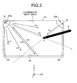
FIG. 2 is a diagram that illustrates a method for obtaining the positional information on a desired position that is on a touch panel and that is pointed by using a pointing unit; -
FIG. 3 is a diagram that illustrates a method for obtaining the positional information on a desired position that is on the touch panel and that is pointed by using the pointing unit; -
FIG. 4 is a diagram that illustrates a method for obtaining the positional information on a desired position that is on the touch panel and that is pointed by using the pointing unit; -
FIG. 5 is a diagram that illustrates a method for obtaining the positional information on a desired position that is on the touch panel and that is pointed by using the pointing unit; -
FIG. 6 is a diagram that illustrates an optical system that is included in the optical touch panel device; -
FIG. 7 is a diagram that illustrates a configuration of a stylus pen that is included in the optical touch panel device; -
FIG. 8 illustrates states where a desired position on the touch panel is pointed by using the stylus pen according to the present embodiment; -
FIG. 9 illustrates states where a desired position on the touch panel is pointed by using a stylus pen according to a comparative example; -
FIG. 10 illustrates a movable pen tip of a stylus pen according to a first modified example and a second modified example in an extracted manner; -
FIG. 11 illustrates a movable pen tip of a stylus pen according to a third modified example and a fourth modified example in an extracted manner; and -
FIG. 12 illustrates a hardware configuration of an optical touch panel device according to another embodiment of the present invention. - Exemplary embodiments of the present invention are explained in detail below with reference to the accompanying drawings.
FIG. 1 illustrates a schematic configuration of an opticaltouch panel device 100 according to an embodiment. - As illustrated in
FIG. 1 , the opticaltouch panel device 100 includes, for example, astylus pen 10, a touch panel 12 (not illustrated inFIG. 1 , seeFIG. 2 ), a touch-panel control unit 14, a personal computer (PC)unit 16, or the like. Here, the opticaltouch panel device 100 serves as what is called an electronic blackboard. - The
stylus pen 10 is a pointing device that is used for pointing a desired position on thetouch panel 12. Thestylus pen 10 will be explained in detail later. - For example, the
touch panel 12 is shaped like a rectangular plate. In the following, an explanation is given by using an XYZ three-dimensional orthogonal coordinate system where the longitudinal direction of thetouch panel 12 is the direction of an axis X, the lateral direction thereof is the direction of an axis Y, and the direction (the thickness direction of the touch panel 12) perpendicular to the direction of the axis X and the direction of the axis Y is the direction of an axis Z. - A first light emitting/receiving
unit 20a is provided on the end of thetouch panel 12 on, for example, the -X and +Y side thereof, and a second light emitting/receivingunit 20b is provided on the end of thetouch panel 12 on, for example, the +X and +Y side. Here, the first and second light emitting/receivingunits light emitting unit 83 and alight receiving unit 50. -
Retroreflective members 24 are provided on the edges of thetouch panel 12 on the +X side, -X side, and -Y side. Each of theretroreflective members 24 has characteristics such that it reflects an incident light in the direction opposite (the direction reverse) to the incident direction regardless of the incident angle. - The touch-
panel control unit 14 includes a positional-information calculation unit 14a that calculates the positional information (XY coordinates) on a desired position that is on thetouch panel 12 and that is pointed by using thestylus pen 10; and acontrol unit 14b that outputs the positional information to thePC unit 16 as appropriate. The positional-information calculation unit 14a will be explained in detail later. - With reference back to
FIG. 1 , thePC unit 16 includes asignal input unit 16a that inputs the positional information from thecontrol unit 14b; asignal processing unit 16b that processes a signal from thesignal input unit 16a; an operating system (OS) 16c that outputs the processing details on the basis of the signal that is processed by thesignal processing unit 16b; and anapplication 16d that uses the processing details from theOS 16c. - Here, an explanation is given, with reference to
FIG. 2 , of an example of the principle of pointed-position detection performed by the opticaltouch panel device 100. First, a desired position (a pointed position P) on thetouch panel 12 of the opticaltouch panel device 100 is pressed and pointed by using apointing unit 2, such as a user's finger, pen, or pointer, which includes an optically opaque component. The positional information (XY coordinates) on the pointed position is detected so that theapplication 16d can be finally executed. - Furthermore, the first light emitting/receiving
unit 20a emits the flux of multiple light beams L1, L2, L3, ..., and Ln (probe light) along thetouch panel 12. Specifically, the probe light is a light wave that travels from the first light emitting/receivingunit 20a and expands in a fan-like form along thetouch panel 12. In the same manner, the second light emitting/receivingunit 20b emits the flux of multiple light beams (probe light) along thetouch panel 12. - One of the fan-like light waves from the first light emitting/receiving
unit 20a, i.e., the light beam Lm is reflected by theretroreflective member 24 on the -Y side, and a retroreflected light Lm' returns to the first light emitting/receivingunit 20a through the same optical path as the light beam Lm. In this case, it can be determined whether the retroreflected light of each of the light beams L1 to Ln returns to the first light emitting/receivingunit 20a. In the same manner, it can be determined whether the retroreflected light of each of the light beams emitted by the second light emitting/receivingunit 20b returns to the second light emitting/receivingunit 20b. - When a user touches the pointed position P on the
touch panel 12 with, for example, his/her finger, the light beam Lk is blocked by the finger at the pointed position P and does not reach theretroreflective member 24. In this case, as the retroreflected light of the light beam Lk is not received by the first light emitting/receivingunit 20a, it can be determined that a light shielding object exists on the optical path (on a straight line L) of the light beam Lk. In the same manner, as the retroreflected light of the light beam Lj emitted by the second light emitting/receivingunit 20b is not received by the second light emitting/receivingunit 20b, it can be determined that a light shielding object exists on the optical path (on a straight line R) of the light beam Lj. - In this case, the straight line L and the straight line R are determined, and the coordinates of the intersection point of the straight lines are calculated, whereby it is possible to determine the XY coordinates of the pointed position P on the
touch panel 12. - Next, an explanation is given of a configuration of the first light emitting/receiving
unit 20a and a method of detecting which light beam is blocked by thestylus pen 10 among the light beams L1 to Ln. -
FIG. 3 schematically illustrates the configuration of the first light emitting/receivingunit 20a. The first light emitting/receivingunit 20a includes, in addition to the above-described light receiving/emitting device, anoptical system 90 that includes apoint light source 81 and acondensing lens 51, or the like. In the following, an explanation is given by using an xyz three-dimensional orthogonal coordinate system (seeFIG. 3 ) where the direction of the optical axis of thecondensing lens 51 is the direction of an axis x, the direction perpendicular to the direction of the axis x on a plane parallel to thetouch panel 12 is the direction of an axis y, and the direction perpendicular to the direction of the axis x and the direction of the axis y is the direction of an axis z. Furthermore, the direction of the axis z is parallel to the direction of the axis Z. - For example, the
point light source 81 is provided on the +x side of thelight receiving unit 50 and in the vicinity of the center of thecondensing lens 51 so as to emit, to the +x side, fan-like light that is parallel to the xy plane. For example, thelight receiving unit 50 is provided in the vicinity of the focus position of thecondensing lens 51 such that the light receiving surface of thelight receiving unit 50 is perpendicular to the axis x. The fan-like light that is emitted by thepoint light source 81 is the flux of light beams that travel in the direction of the arrow α, in the direction of the arrow β, and in the other directions. - The light beam that travels in the direction of the arrow α is reflected by the
retroreflective member 24, is condensed by thecondensing lens 51, and then reaches a light received position p1 on thelight receiving unit 50. Furthermore, the light beam that travels in the direction of the arrow β is reflected by theretroreflective member 24, is condensed by the condensinglens 51, and then reaches a light received position p2 on thelight receiving unit 50. - As described above, after multiple light beams are emitted by the point
light source 81, are reflected by theretroreflective member 24, and are returned through the corresponding optical path, they reach different positions on thelight receiving unit 50 due to the effect of the condensinglens 51. At that time, when a given position on thetouch panel 12 is pointed by using thepointing unit 2 and a corresponding light beam is blocked, light does not reach the point that is on thelight receiving unit 50 and that corresponds to the light beam. - Therefore, the examination on the light intensity distribution on the
light receiving unit 50 makes it possible to determine which one of the beams is blocked. - As illustrated in
FIG. 4 , after light is emitted by the first light emitting/receivingunit 20a to the +x side, the light is reflected by theretroreflective member 24, and is returned to the pointlight source 81 through the same optical path. After returning from theretroreflective member 24, the retroreflected light passes through the center of the condensinglens 51 and travels to the -x side of the condensing lens 51 (the side of the light receiving unit 50) through the optical path that is point-symmetric with respect to the center of the condensinglens 51. - Here, if the
pointing unit 2 is not in contact with or is not located close to thetouch panel 12, the light intensity distribution on the entire area of thelight receiving unit 50 is nearly constant. Conversely, as illustrated inFIG. 4 , if thepointing unit 2 is in contact with the arbitrary pointed position P on thetouch panel 12, the beam that travels from the first light emitting/receivingunit 20a toward the pointed position P is blocked, whereby a low light-intensity area (dark point) is generated on a position Dn of thelight receiving unit 50. The position Dn corresponds to the outgoing/incoming angle θn of the blocked beam, and θn can be determined by detecting Dn. That is, θn can be represented by using the following Equation (1) as a function of Dn.
- Furthermore, Dn is equivalent to the y-coordinate of a light received position pn, where the origin thereof is the intersection point between the light receiving surface of the
light receiving unit 50 and the straight line that is parallel to the axis x that passes through the center of the condensinglens 51. - Here, particularly, θn in
FIG. 4 is replaced with θnL, and Dn with DnL. Furthermore, as illustrated inFIG. 5 , due to conversion g of the geometric positional relationship between the first light emitting/receivingunit 20a and the coordinate input area (pointed area) of thetouch panel 12, an angle θL formed by the axis X and a straight line AP connecting a position A of the first light emitting/receivingunit 20a and the pointed position P on thetouch panel 12 is represented by using the following Equation (2) as a function of DnL that is determined by using the above-described Equation (1).
- In the same manner, with respect to the second light emitting/receiving
unit 20b, L in the above-described Equation (2) is replaced with R and, due to conversion h of the geometric positional relationship between the second light emitting/receivingunit 20b and the coordinate input area of thetouch panel 12, an angle θR formed by the axis X and a straight line BP connecting a position B of the second light emitting/receivingunit 20b and the pointed position P on thetouch panel 12 is represented by using the following Equation (3).
- Here, the first light emitting/receiving
unit 20a is installed in the coordinate input area with an interval W as illustrated inFIG. 5 , and the coordinates (X, Y) of the pointed position P on the coordinate input area are represented by using the following Equations (4) and (5).

- As described above, X and Y can be represented as the functions of DnL and DnR. In this case, the positions DnL and DnR of the dark points on the
light receiving units 50 in the first and second light emitting/receivingunits pointing unit 2. - Next, an explanation is given of an example of the
optical system 90 that includes the condensinglens 51.FIG. 6 illustrates a state where a single light emitting/receiving unit is provided on thetouch panel 12. - Here, a light source that is used as the
light emitting unit 83 is, for example, a laser diode or pinpoint LED, capable of emitting light having a certain degree of directivity. Thelight emitting unit 83 emits light in the -Z direction. Furthermore, for example, a photo diode or photo transistor is used as thelight receiving unit 50. - The
optical system 90 includes, in addition to the above-describedcondensing lens 51, a cylindrical lens group that includes threecylindrical lenses light emitting unit 83; aslit plate 82 that is provided on the optical path of light that passes through the cylindrical lens group; ahalf mirror 87 that is provided on the optical path of light that passes through theslit plate 82; or the like. - After light is emitted by the
light emitting unit 83 in the -Z direction, the light is collimated by thecylindrical lens 84 in only the direction of the axis X and is then condensed in the direction of the axis Y by the twocylindrical lenses cylindrical lens 84. A section Q inFIG. 6 is a diagram of thelight emitting unit 83, the cylindrical lens group, and theslit plate 82 when viewed from the +X side. Due to the effect of the cylindrical lens group, the light is shaped in the form of a line that extends in the direction of the axis X in cross-section and is emitted to the -Z side of thecylindrical lens 86. The light from thecylindrical lens 86 is incident on theslit plate 82 on which an elongated slit is formed and extends in the direction of the axis X, whereby the pointlight source 81 is formed as a secondary light source. In the following, the pointlight source 81 is also referred to as the secondarylight source 81 for convenience. - Specifically, the secondary
light source 81 is formed at the position of the slit of theslit plate 82 so as to emit linear light that extends in the direction of the axis X in cross-section. The light from the secondarylight source 81 is reflected by thehalf mirror 87 to the +X side so as to travel along thetouch panel 12 as a parallel light that does not expand in the direction of the axis Z but, in a direction parallel to thetouch panel 12, expands in a fan-like form with the secondarylight source 81 at the center. The traveling light is reflected by theretroreflective member 24 that is provided on the outer edge of thetouch panel 12 and is returned to the side of the half mirror 87 (in the direction of the arrow C inFIG. 6 ) through the same path. After transmitting through thehalf mirror 87, the light travels in parallel to thetouch panel 12, passes through the condensinglens 51, and is incident on thelight receiving unit 50. - Here, the secondary
light source 81 and the condensinglens 51 have a conjugated positional relationship with respect to the half mirror 87 (see the arrow D inFIG. 6 ). Furthermore, a section V inFIG. 6 is a diagram of thelight receiving unit 50 and the condensinglens 51 when viewed in the +Z direction. The above-describedoptical system 90 may be changed as appropriate. - Next, an explanation is given of the positional-
information calculation unit 14a. The positional-information calculation unit 14a calculates the positional information (XY coordinates) of the pointed position P by using the principle of triangulation and by using a light received signal from the light receiving unit of each of the light emitting/receiving units that are provided in the above-described opticaltouch panel device 100, and then outputs it to thesignal input unit 16a via thecontrol unit 14b at a predetermined rate. - The coordinate value of the pointed position P and a light blocked signal are output from the positional-
information calculation unit 14a at a predetermined rate and are input to thesignal processing unit 16b (driver) via thesignal input unit 16a. With regard to the light blocked signal, when the light is blocked by thestylus pen 10 in the opticaltouch panel device 100, "the light blocked signal = true" and, otherwise, "the light blocked signal = false". The coordinate value of the pointed position P is a valid value when the light blocked signal is true and, it is an invalid value when the light blocked signal is false. - A detailed explanation is given below of the
stylus pen 10 with reference toFIGS. 7 to8C . As illustrated inFIG. 7 , thestylus pen 10 extends along a predetermined axis line. As illustrated inFIG. 7 , thestylus pen 10 includes, for example, agrip section 102 that is constituted by a substantially cylindrical and elongated member that extends in the direction of the above-described axis line; amovable pen tip 104 that is attached to thegrip section 102; and apressure detection unit 105. - For example, the
movable pen tip 104 is constituted by a member that extends in the direction of the above-described axis line and includes anend 104a that is constituted by a spherical light shielding member. The above-described axis line passes through the central part (the center of gravity) C of theend 104a. That is, theend 104a (the light shielding member) has a symmetrical shape with respect to the above-described axis line. In the following, theend 104a is also referred to as thelight shielding member 104a for convenience. - In this case, the distance is constant between the central part C, which is a predetermined part on the above-described axis line in the
light shielding member 104a, and an arbitrary area on the surface (outer circumference) of theend 104a. - Here, the "light shielding member" refers to an object that blocks at least part of incident light. In the present embodiment, an object that blocks all incident light is used as an example of the light shielding member. In this case, the position of a shadow that the incident light does not reach can be detected in a stable and accurate way.
- A
base end section 104b of themovable pen tip 104 is engaged with a recessedsection 102a that is formed on an end surface of thegrip section 102. Furthermore, themovable pen tip 104 is coupled to thegrip section 102 via, for example, an elastic member such that themovable pen tip 104 is movable relative to thegrip section 102 in the direction of the axis line of thegrip section 102 at a predetermined stroke. - The
pressure detection unit 105 includes, for example, apressure sensor 106, and asignal processing circuit 108 that processes a detection signal from thepressure sensor 106. - The
pressure sensor 106 is attached to the bottom surface of the recessedsection 102a. Specifically, thepressure sensor 106 is provided between themovable pen tip 104 and the bottom surface of the recessedsection 102a. Thepressure sensor 106 changes a resistance value in accordance with applied pressure, and it is, for example, FlexiForce that is manufactured by Nitta Corporation, INASTOMER that is manufactured by INABA RUBBER Co., Ltd, or the like. - When the
end 104a of themovable pen tip 104 is brought into contact with thetouch panel 12, themovable pen tip 104 is moved toward thepressure sensor 106 so that thepressure sensor 106 is pressed. - In the following, a true/false signal that is input from the
pressure detection unit 105 to thesignal processing unit 16b via thesignal input unit 16a is referred to as a pressure signal. Specifically, when themovable pen tip 104 is in physical contact with thetouch panel 12, "the pressure signal = true" in thesignal processing unit 16b and, otherwise, "the pressure signal = false". - The
signal processing circuit 108 includes a conversion circuit that converts a change in the resistance value of thepressure sensor 106 into a voltage; an A/D conversion circuit that converts the voltage into a digital value; a memory circuit that stores a predetermined threshold; a threshold processing circuit that compares the pressure signal, which is converted into the digital value, with the threshold stored in the memory circuit, outputs "true" if the pressure signal exceeds the threshold, and, otherwise, outputs "false"; and an output circuit that sends, to thesignal processing unit 16b via thesignal input unit 16a, a logical value that is output from the threshold processing circuit at a predetermined rate. - A user points a desired position (pointed position) on the
touch panel 12 by bringing an arbitrary area that is part of the surface of theend 104a (light shielding member) of thestylus pen 10, which is configured as described above, into contact with the desired position. - Here, as described above, the
end 104a of thestylus pen 10 is spherical; therefore, when theend 104a is in contact with an arbitrary position on thetouch panel 12, the width (the width in a direction along the touch panel 12) of blocked light that is emitted by each of the light emitting/receiving units is constant regardless of the tilt angle of thestylus pen 10 with respect to the touch panel 12 (see (A) to (C) ofFIG. 8 ). In this case, the width of the dark point illustrated inFIG. 4 and the center position thereof are not changed regardless of the tilt angle of thestylus pen 10. Specifically, the center position of the shadow (light blocked image) that occurs due to light blocking of theend 104a is not changed regardless of the tilt angle of thestylus pen 10. As a result, the positional information (XY coordinates) calculated by the positional-information calculation unit 14a is not changed regardless of the tilt angle of thestylus pen 10. - A detailed explanation is given below of the above effect. As illustrated in
FIGS. 8 and9 , light is emitted by the light emitting/receiving unit that is provided on, for example, the back side with respect to the drawing plane, part of the light is blocked on the pointed position that is pointed by using thestylus pen 10, and the remaining part thereof is transmitted, is reflected by an undepicted retroreflective member that is provided on the front side with respect to the drawing plane in a retroreflective manner, and is returned to the light emitting/receiving unit. - In (A) to (C) of
FIG. 8 , w1 to w3 indicate the width of light that is blocked by theend 104a of themovable pen tip 104 when a desired position on thetouch panel 12 is pointed by using thestylus pen 10 according to the present embodiment. InFIG. 8, (A) illustrates a state where the axis line of thestylus pen 10 is perpendicular to thetouch panel 12. InFIG. 8, (B) illustrates a state where the axis line of thestylus pen 10 is tilted with respect to thetouch panel 12 at a tilt angle φ1.FIG. 8C illustrates a state where the axis line of thestylus pen 10 is tilted with respect to thetouch panel 12 at a tilt angle φ2 (<φ1). - Here, as the
end 104a of thestylus pen 10 is spherical, the width of blocked light is not changed regardless of the angle that is formed between the axis line of thestylus pen 10 and thetouch panel 12; thus, w1 = w2 = w3. Furthermore, as the XY coordinates of the central part (the center of gravity) of theend 104a (light shielding member) match the XY coordinates of the area of theend 104a that is in contact with thetouch panel 12 regardless of the above-described angle; therefore, the center position of the shadow (light blocked image) that occurs due to light blocking of theend 104a (the position of the dark point detected on the light receiving unit 50) is not changed regardless of the above-described angle. As a result, the actual XY coordinates of the position on thetouch panel 12 that is in contact with theend 104a match the XY coordinates that are calculated by the positional-information calculation unit 14a regardless of the above-described angle. That is, it is possible to determine the XY coordinates of the area that is on thetouch panel 12 and that is in contact with theend 104a in a stable and accurate manner. - In (A) to (C) of
FIG. 9 , w4 to w6 indicate the width of light that is blocked by an end SPa of a stylus pen SP when an arbitrary position on the touch panel is pointed by using the stylus pen SP in a comparative example. InFIG. 9, (A) illustrates a state where the axis line of the stylus pen SP is perpendicular to the touch panel. InFIG. 9, (B) illustrates a state where the axis line of the stylus pen SP is tilted with respect to the touch panel at a tilt angle φ1'. InFIG. 9, (C) illustrates a state where the axis line of the stylus pen SP is tilted with respect to the touch panel at a tilt angle φ2' (<φ1'). - Here, the end SPa (the light shielding member) of the stylus pen SP in the comparative example has a tapered and substantially conical shape. That is, in the comparative example, only the shape of the end of the stylus pen is different from that in the present embodiment. In this case, the width of blocked light is different depending on the angle that is formed between the axis line of the stylus pen SP and the touch panel, and therefore w4 ≠ w5 ≠ w6. Furthermore, the XY coordinates of the center of gravity of the end SPa is different from the XY coordinates of the position of the touch panel that is in contact with the end SPa depending on the above-described angle; therefore, the center position of the shadow (light blocked image) that occurs due to light blocking of the end SPa (the position of the dark point detected on the light receiving unit) is different depending on the above-described angle. As a result, the XY coordinates of the position on the touch panel that is in contact with the end SPa is different from the XY coordinates that are calculated by the positional-information calculation unit depending on the above-described angle. That is, it is difficult to determine the XY coordinates of the area that is on the touch panel and that is in contact with the end SPa in a stable and accurate way. As a result, in the comparative example, although the same position on the touch panel is pointed by using the stylus pen SP, the positional information (XY coordinates) calculated by the positional-information calculation unit is changed in accordance with the tilt angle of the stylus pen SP.
- The above-described
stylus pen 10 according to the present embodiment is a stylus that is used for pointing a desired position on thetouch panel 12 that is included in the opticaltouch panel device 100. Thestylus pen 10 extends along a predetermined axis line, and an arbitrary area that is part of the surface of theend 104a is brought into contact with the desired position. Theend 104a includes thelight shielding member 104a that blocks all incident light, the axis line passes through the central part C of thelight shielding member 104a, and the distance is constant between a predetermined part (the central part C) on the axis line in thelight shielding member 104a and the arbitrary area. - In this case, the positional information on the position of the
touch panel 12 that is in contact with the surface of thelight shielding member 104a on the plane that is parallel to thetouch panel 12 matches the positional information on the central part C of thelight shielding member 104a on the plane that is parallel to thetouch panel 12 regardless of the tilt angle of thestylus pen 10 with respect to thetouch panel 12. - As a result, it is possible to stably and accurately determine the positional information on a desired position that is on the
touch panel 12 and that is pointed by using thestylus pen 10. - Furthermore, as the
light shielding member 104a included in theend 104a has a spherical shape, it is easier to recognize thelight shielding member 104a on first sight regardless of the tilt angle of thestylus pen 10, compared to, for example, the above-described comparative example and, without forming a mark, such as an engraved mark, on thelight shielding member 104a, thelight shielding member 104a can be easily brought into contact with a desired position on thetouch panel 12. As a result, it is possible to improve the operational performance of thestylus pen 10. - Although the
end 104a of thestylus pen 10 is constituted by a spherical light shielding member in the above-described embodiment, this is not a limitation, and it is applicable if the distance is constant between a predetermined area on the above-described axis line in the light shielding member and an arbitrary area that is on the surface of the end of the stylus pen and that is in contact with thetouch panel 12. - Specifically, as illustrated in a first modified example in (A) of
FIG. 10 , for example, part of the end of a movable pen tip, which is symmetrical with respect to the above-described axis line and is formed of at least the half of a sphere, may be constituted by a light shielding member that is formed of a sphere whose center matches the center of the above sphere. In this case, the distance is constant between a central part C1 that is a predetermined part on the above-described axis line in the light shielding member and an arbitrary area that is on the surface of the end of the movable pen tip and that is contact with thetouch panel 12. - Furthermore, as illustrated in a second modified example in (B) of
FIG. 10 , for example, part of the end of a movable pen tip, which is symmetrical with respect to the above-described axis line and is formed of at least the half of a sphere, may be constituted by a light shielding member that is formed of at least the half of a sphere whose center matches the center of the above sphere and which is symmetric with respect to the above-described axis line. In this case, the distance is constant between a predetermined part C2 on the above-described axis line in the light shielding member and an arbitrary area that is on the surface of the end of the movable pen tip and that is contact with thetouch panel 12. - Furthermore, as illustrated in a third modified example (1 and 2) in (A) and (B) of
FIG. 11 , for example, at least part of the end of a movable pen tip, which is symmetrical with respect to the above-described axis line and is formed of at least the half of a sphere, may be constituted by a light shielding member that is formed of at least the half of a sphere whose center matches the center of the above sphere and which is symmetric with respect to the above-described axis line. In this case, the distance is constant between a predetermined part C3 (C4) on the above-described axis line in the light shielding member and an arbitrary area that is on the surface of the end of the movable pen tip and that is contact with thetouch panel 12. - Furthermore, in the above-described embodiment and each of the modified examples, the light shielding member is a henagon (a figure formed by one surface) or dihedron that is formed of at least the half of a sphere; however, it may be a polyhedron (e.g., regular polyhedron) that has three or more faces. In this case, it is preferable that the above-described axis line passes through the center of gravity of the light shielding member and the distance is constant between a predetermined area on the above-described axis line in the light shielding member and an arbitrary area that is on the surface of the end of the stylus and that is in contact with the
touch panel 12. - Furthermore, in the above-described embodiment and each of the modified examples, the
end 104a of thestylus pen 10 is brought into contact with a desired position on thetouch panel 12 so that the desired position is pointed; additionally or alternatively, for example, the end of the stylus pen may be located close to a desired position on the touch panel (without being brought into contact) so that the desired position is pointed. In this case, thepressure detection unit 105 may not be provided. - Moreover, in the above-described embodiment and each of the modified examples, the light shielding member that blocks all incident light is used; however, instead of this, the one that blocks part of incident light may be used.
- Moreover, in the above-described embodiment and each of the modified examples, the end of the stylus pen has a shape such that an arbitrary area that is part of the surface thereof is brought into contact with a desired position on the
touch panel 12; however, it may have a shape (e.g., semispherical shape) such that the arbitrary area that is the entire surface is brought into contact with a desired position on thetouch panel 12. - Furthermore, in the above-described embodiment and each of the modified examples, the axis line that passes through the center of gravity of the light shielding member matches the axis line of the stylus; however, they may not match.
- Moreover, in the above-described embodiment, an electronic blackboard that includes a large-sized touch panel is used as the optical
touch panel device 100; however, this is not a limitation and, for example, a tablet terminal that includes a small-sized touch panel may be used. -
FIG. 12 is a diagram that illustrates a hardware configuration of an optical touch panel device according to another embodiment of the present invention. An opticaltouch panel device 1100 is an information processing apparatus that has been developed for a coordinate detection system. The opticaltouch panel device 1100 includes aCPU 1101, aROM 1102, aRAM 1103, anSSD 1104, anetwork controller 1105, anexternal storage controller 1106, asensor controller 1114, aGPU 1112, and acapture device 1111 that are electrically connected to one another via abus line 1118, such as an address bus or data bus. - The
CPU 1101 executes an application so as to control the overall operation of the opticaltouch panel device 1100 that is the coordinate detection system. TheROM 1102 stores an IPL, or the like, and primarily stores a program that is executed by theCPU 1101 during a start-up. TheRAM 1103 is a work area when theCPU 1101 executes an application. TheSSD 1104 is a non-volatile memory that stores anapplication 1119 or various types of data for the coordinate detection system. Thenetwork controller 1105 performs processing on the basis of a communication protocol during a communication with a server, or the like, via an undepicted network. The network is a LAN, WAN (e.g., the Internet) in which a plurality of LANs are connected, or the like. - The
external storage controller 1106 writes to or reads from anexternal memory 1117 that is attachable and removable. Theexternal memory 1117 is, for example, a USB memory or SD card. Thecapture device 1111 fetches (captures) an image that is displayed on a display device by aPC 1300. TheGPU 1112 is a processor that is dedicated to drawing and that calculates the pixel value of each pixel of adisplay 1200. Adisplay controller 1113 outputs the image generated by theGPU 1112 to thedisplay 1200. - The
sensor controller 1114 is connected to fourdetection units 1011 and detects the coordinates by using a triangulation method that uses an infrared light blocking or pen emission method. - In the present embodiment, the optical
touch panel device 1100 has a function to communicate with thestylus pen 10. Thestylus pen 10 has a unit for sending signals to the opticaltouch panel device 1100. As illustrated inFIG. 12 , the opticaltouch panel device 1100 has astylus pen controller 1116 so as to receive a pressure signal from thestylus pen 10. Thus, the opticaltouch panel device 1100 is capable of detecting whether the end of thestylus pen 10 is pressed. - The application for the coordinate detection system may be distributed as being stored in the
external memory 1117 or may be downloaded from an undepicted server via thenetwork controller 1105. The application may be in a compressed state or in an executable format. - Thus, it is possible to stably and accurately determine the positional information on a desired position that is on a touch panel and that is pointed by using a stylus.
- Although the invention has been described with respect to specific embodiments for a complete and clear disclosure, the appended claims are not to be thus limited but are to be construed as embodying all modifications and alternative constructions that may occur to one skilled in the art that fairly fall within the basic teaching herein set forth.
Claims (9)
- A stylus (10), comprising
an end having a surface, an arbitrary area of which is to be moved close to or brought into contact with a desired position on a touch panel (12) of an optical touch panel device (100), the end including a light shielding member (104a) configured to block at least part of incident light, wherein
the stylus (10) extends along an axis line that passes through a center of gravity (C) of the light shielding member (104a), and
a distance between a predetermined part of the light shielding member (104a) on the axis line and the arbitrary area is constant. - The stylus (10) according to claim 1, wherein the light shielding member (104a) has a symmetrical shape with respect to the axis line.
- The stylus (10) according to claim 2, wherein the light shielding member (104a) is formed of at least a half of a sphere.
- The stylus according to any one of claims 1 to 3, wherein the end is formed of at least a half of a sphere that has a symmetrical shape with respect to the axis line.
- The stylus (10) according to claim 4, wherein an inside part of the end is formed from the light shielding member (104a).
- The stylus (10) according to any one of claims 1 to 5, further comprising a pressure detection unit (105) configured to detect a pressure applied to the end when the arbitrary area is in contact with the desired position.
- An optical touch panel device (100), comprising:the stylus (10) according to any one of claims 1 to 6;the touch panel (12) which has a rectangular plate shape and on which the desired position is pointed by using the stylus (10);a pair of light emitting/receiving devices (20a, 20b) each configured to include a light emitting unit (83) and a light receiving unit (50), the light emitting/receiving devices (20a, 20b) being separately provided on two ends of the touch panel (12);a retroreflective member (24) configured to reflect incident light into a direction opposite to an incident direction, the retroreflective member (24) being provided along an outer edge of the touch panel (12);optical systems (90) provided for the light emitting/receiving devices (20a, 20b), respectively, each optical system being configured to guide light emitted from the light emitting unit (83) of the corresponding light emitting/receiving device (20a, 20b) into the retroreflective member (24) so that the light travels along the touch panel (12), and guide the light reflected by the retroreflective member (24) into the light receiving unit (50) of the corresponding light emitting/receiving device (20a, 20b); anda positional-information calculation unit (14a) configured to, in response to pointing the desired position by the stylus (10), calculate positional information of the desired position by using positional information on a shadow that occurs when light emitted by each of the light emitting/receiving devices (20a, 20b) is blocked by the light shielding member (104a) of the stylus (10).
- The optical touch panel device (100) according to claim 7, wherein each optical system is configured to shape the light in a form of a line that extends in a direction perpendicular to the touch panel (12) in cross-section, the light traveling along the touch panel.
- The optical touch panel device (100) according to claim 7 or 8, wherein the light emitting unit (83) is configured to emit directional light.
Applications Claiming Priority (2)
| Application Number | Priority Date | Filing Date | Title |
|---|---|---|---|
| JP2013046595 | 2013-03-08 | ||
| JP2014009533A JP2014197384A (en) | 2013-03-08 | 2014-01-22 | Stylus, and optical touch panel device |
Publications (1)
| Publication Number | Publication Date |
|---|---|
| EP2775378A1 true EP2775378A1 (en) | 2014-09-10 |
Family
ID=50184734
Family Applications (1)
| Application Number | Title | Priority Date | Filing Date |
|---|---|---|---|
| EP14155666.2A Withdrawn EP2775378A1 (en) | 2013-03-08 | 2014-02-19 | Stylus and optical touch panel device |
Country Status (4)
| Country | Link |
|---|---|
| US (1) | US20140253514A1 (en) |
| EP (1) | EP2775378A1 (en) |
| JP (1) | JP2014197384A (en) |
| CN (1) | CN104035594B (en) |
Families Citing this family (9)
| Publication number | Priority date | Publication date | Assignee | Title |
|---|---|---|---|---|
| JP2016020891A (en) | 2014-06-20 | 2016-02-04 | 株式会社リコー | Shape measurement system and imaging device |
| CN108369470B (en) * | 2015-12-09 | 2022-02-08 | 平蛙实验室股份公司 | Improved stylus recognition |
| JP2017111589A (en) | 2015-12-16 | 2017-06-22 | 株式会社リコー | Coordinate detection device, display system, projection system and coordinate detection method |
| TWI662353B (en) * | 2018-07-13 | 2019-06-11 | 松翰科技股份有限公司 | Optical image sensing module |
| CN109495628B (en) * | 2018-11-07 | 2021-04-06 | 南京溧水高新创业投资管理有限公司 | Mobile phone or tablet protection shell with writing function |
| CN109471542B (en) * | 2018-11-07 | 2022-08-26 | 合肥禾斗技汇科技有限公司 | Positioning system |
| CN109471543B (en) * | 2018-11-07 | 2022-08-23 | 合肥禾斗技汇科技有限公司 | Notebook capable of storing handwriting |
| CN109445637B (en) * | 2018-11-07 | 2022-08-19 | 合肥禾斗技汇科技有限公司 | Handwriting processing method based on pen point position |
| JP2023512682A (en) | 2020-02-10 | 2023-03-28 | フラットフロッグ ラボラトリーズ アーベー | Improved touch detector |
Citations (7)
| Publication number | Priority date | Publication date | Assignee | Title |
|---|---|---|---|---|
| JPS57152033A (en) * | 1981-03-13 | 1982-09-20 | Hitachi Ltd | Input pen for tablet input |
| US6570103B1 (en) * | 1999-09-03 | 2003-05-27 | Ricoh Company, Ltd. | Method and apparatus for coordinate inputting capable of effectively using a laser ray |
| JP4627781B2 (en) | 1998-05-11 | 2011-02-09 | 株式会社リコー | Coordinate input / detection device and electronic blackboard system |
| US20120162146A1 (en) * | 2010-12-27 | 2012-06-28 | Hon Hai Precision Industry Co., Ltd. | Touch pen |
| EP2500801A2 (en) * | 2011-03-14 | 2012-09-19 | Ricoh Company, Ltd. | Display device with touch panel, event switching control method, and computer program |
| US20120327043A1 (en) * | 2011-06-27 | 2012-12-27 | Chia-Yu Chang | Stylus capable of being applied in various touch panels |
| US20130002536A1 (en) * | 2011-06-30 | 2013-01-03 | Seiko Epson Corporation | Indication member, optical position detection device, and display system with input function |
Family Cites Families (4)
| Publication number | Priority date | Publication date | Assignee | Title |
|---|---|---|---|---|
| EP2238485B1 (en) * | 2008-01-14 | 2021-12-08 | Avery Dennison Corporation | Retroreflector for use in touch screen applications and position sensing systems |
| US8350829B2 (en) * | 2008-01-15 | 2013-01-08 | Sharp Kabushiki Kaisha | Input pen for touch-panel and touch-panel input system |
| KR100992558B1 (en) * | 2010-04-22 | 2010-11-08 | 엑스지 솔루션스 엘엘씨 | Stylus pen for using a mobile terminal |
| TWI470485B (en) * | 2012-03-29 | 2015-01-21 | Wistron Corp | Stylus capable of detecting pressure on a tip |
-
2014
- 2014-01-22 JP JP2014009533A patent/JP2014197384A/en active Pending
- 2014-02-19 EP EP14155666.2A patent/EP2775378A1/en not_active Withdrawn
- 2014-02-25 US US14/189,115 patent/US20140253514A1/en not_active Abandoned
- 2014-03-05 CN CN201410079600.1A patent/CN104035594B/en not_active Expired - Fee Related
Patent Citations (7)
| Publication number | Priority date | Publication date | Assignee | Title |
|---|---|---|---|---|
| JPS57152033A (en) * | 1981-03-13 | 1982-09-20 | Hitachi Ltd | Input pen for tablet input |
| JP4627781B2 (en) | 1998-05-11 | 2011-02-09 | 株式会社リコー | Coordinate input / detection device and electronic blackboard system |
| US6570103B1 (en) * | 1999-09-03 | 2003-05-27 | Ricoh Company, Ltd. | Method and apparatus for coordinate inputting capable of effectively using a laser ray |
| US20120162146A1 (en) * | 2010-12-27 | 2012-06-28 | Hon Hai Precision Industry Co., Ltd. | Touch pen |
| EP2500801A2 (en) * | 2011-03-14 | 2012-09-19 | Ricoh Company, Ltd. | Display device with touch panel, event switching control method, and computer program |
| US20120327043A1 (en) * | 2011-06-27 | 2012-12-27 | Chia-Yu Chang | Stylus capable of being applied in various touch panels |
| US20130002536A1 (en) * | 2011-06-30 | 2013-01-03 | Seiko Epson Corporation | Indication member, optical position detection device, and display system with input function |
Also Published As
| Publication number | Publication date |
|---|---|
| CN104035594B (en) | 2017-11-14 |
| JP2014197384A (en) | 2014-10-16 |
| US20140253514A1 (en) | 2014-09-11 |
| CN104035594A (en) | 2014-09-10 |
Similar Documents
| Publication | Publication Date | Title |
|---|---|---|
| EP2775378A1 (en) | Stylus and optical touch panel device | |
| US8542219B2 (en) | Processing pose data derived from the pose of an elongate object | |
| JP6201519B2 (en) | Coordinate detection apparatus, coordinate detection method, and electronic information board system | |
| US9229541B2 (en) | Coordinate detection system, information processing apparatus and method, and computer-readable carrier medium | |
| CN102169394B (en) | Multiple-input touch panel and method for gesture recognition | |
| JP2002049466A5 (en) | ||
| KR20040081854A (en) | Motion recognition system using a imaginary writing plane and method thereof | |
| CN108089772B (en) | Projection touch method and device | |
| EP3416032A1 (en) | Touch control system, touch control display system, and touch control interaction method | |
| JP2004094653A (en) | Information input system | |
| JP2012069095A (en) | Information processing device and control method thereof | |
| US10499039B2 (en) | Path detection system and path detection method generating laser pattern by diffractive optical element | |
| JP2001142643A (en) | Device for inputting/detecting coordinates | |
| JP2019128722A (en) | Information processing device, information processing system, and program | |
| US8854338B2 (en) | Display apparatus and method of controlling display apparatus | |
| KR20120013839A (en) | Apparatus for touch screen | |
| TWI521413B (en) | Optical touch screen | |
| JPH1185376A (en) | Information display device with optical position detecting device | |
| US8912482B2 (en) | Position determining device and method for objects on a touch device having a stripped L-shaped reflecting mirror and a stripped retroreflector | |
| US9170685B2 (en) | Object location determination | |
| CN102063228A (en) | Optical sensing system and touch screen applying same | |
| JP2017016567A (en) | Electronic pen, touch panel device, and control method of electronic pen | |
| JP2013191005A (en) | Digitizer device | |
| JP2001084108A (en) | Device for inputting and detecting and displaying coordinate | |
| JP2000267798A (en) | Coordinate inputting/detecting device |
Legal Events
| Date | Code | Title | Description |
|---|---|---|---|
| PUAI | Public reference made under article 153(3) epc to a published international application that has entered the european phase |
Free format text: ORIGINAL CODE: 0009012 |
|
| 17P | Request for examination filed |
Effective date: 20140219 |
|
| AK | Designated contracting states |
Kind code of ref document: A1 Designated state(s): AL AT BE BG CH CY CZ DE DK EE ES FI FR GB GR HR HU IE IS IT LI LT LU LV MC MK MT NL NO PL PT RO RS SE SI SK SM TR |
|
| AX | Request for extension of the european patent |
Extension state: BA ME |
|
| 17Q | First examination report despatched |
Effective date: 20180524 |
|
| STAA | Information on the status of an ep patent application or granted ep patent |
Free format text: STATUS: THE APPLICATION IS DEEMED TO BE WITHDRAWN |
|
| 18D | Application deemed to be withdrawn |
Effective date: 20181005 |