EP2777437A1 - Multilayer upholstery with zoned and ventilated middle layer and method for producing the same - Google Patents
Multilayer upholstery with zoned and ventilated middle layer and method for producing the same Download PDFInfo
- Publication number
- EP2777437A1 EP2777437A1 EP20140000843 EP14000843A EP2777437A1 EP 2777437 A1 EP2777437 A1 EP 2777437A1 EP 20140000843 EP20140000843 EP 20140000843 EP 14000843 A EP14000843 A EP 14000843A EP 2777437 A1 EP2777437 A1 EP 2777437A1
- Authority
- EP
- European Patent Office
- Prior art keywords
- mattress
- layer
- spring elements
- foam
- cushioning element
- Prior art date
- Legal status (The legal status is an assumption and is not a legal conclusion. Google has not performed a legal analysis and makes no representation as to the accuracy of the status listed.)
- Granted
Links
Images

Classifications
-
- A—HUMAN NECESSITIES
- A47—FURNITURE; DOMESTIC ARTICLES OR APPLIANCES; COFFEE MILLS; SPICE MILLS; SUCTION CLEANERS IN GENERAL
- A47C—CHAIRS; SOFAS; BEDS
- A47C27/00—Spring, stuffed or fluid mattresses or cushions specially adapted for chairs, beds or sofas
- A47C27/14—Spring, stuffed or fluid mattresses or cushions specially adapted for chairs, beds or sofas with foamed material inlays
- A47C27/142—Spring, stuffed or fluid mattresses or cushions specially adapted for chairs, beds or sofas with foamed material inlays with projections, depressions or cavities
- A47C27/144—Spring, stuffed or fluid mattresses or cushions specially adapted for chairs, beds or sofas with foamed material inlays with projections, depressions or cavities inside the mattress or cushion
-
- A—HUMAN NECESSITIES
- A47—FURNITURE; DOMESTIC ARTICLES OR APPLIANCES; COFFEE MILLS; SPICE MILLS; SUCTION CLEANERS IN GENERAL
- A47C—CHAIRS; SOFAS; BEDS
- A47C27/00—Spring, stuffed or fluid mattresses or cushions specially adapted for chairs, beds or sofas
- A47C27/14—Spring, stuffed or fluid mattresses or cushions specially adapted for chairs, beds or sofas with foamed material inlays
- A47C27/148—Spring, stuffed or fluid mattresses or cushions specially adapted for chairs, beds or sofas with foamed material inlays of different resilience
-
- A—HUMAN NECESSITIES
- A47—FURNITURE; DOMESTIC ARTICLES OR APPLIANCES; COFFEE MILLS; SPICE MILLS; SUCTION CLEANERS IN GENERAL
- A47C—CHAIRS; SOFAS; BEDS
- A47C27/00—Spring, stuffed or fluid mattresses or cushions specially adapted for chairs, beds or sofas
- A47C27/14—Spring, stuffed or fluid mattresses or cushions specially adapted for chairs, beds or sofas with foamed material inlays
- A47C27/15—Spring, stuffed or fluid mattresses or cushions specially adapted for chairs, beds or sofas with foamed material inlays consisting of two or more layers
-
- B—PERFORMING OPERATIONS; TRANSPORTING
- B68—SADDLERY; UPHOLSTERY
- B68G—METHODS, EQUIPMENT, OR MACHINES FOR USE IN UPHOLSTERING; UPHOLSTERY NOT OTHERWISE PROVIDED FOR
- B68G11/00—Finished upholstery not provided for in other classes
- B68G11/04—Finished upholstery not provided for in other classes mainly composed of resilient materials, e.g. of foam rubber
-
- B—PERFORMING OPERATIONS; TRANSPORTING
- B68—SADDLERY; UPHOLSTERY
- B68G—METHODS, EQUIPMENT, OR MACHINES FOR USE IN UPHOLSTERING; UPHOLSTERY NOT OTHERWISE PROVIDED FOR
- B68G5/00—Resilient upholstery pads
- B68G5/02—Resilient upholstery pads of cellular material, e.g. sponge rubber
Abstract
Description
Die Erfindung beschreibt ein mehrschichtiges Polsterelement, im Besonderen eine Matratze oder ein Kissen aus Schaumstoff und ein Verfahren zur Herstellung derselben, bei dem das Polsterelement zur Optimierung der punktelastischen Stützung des Nutzers und zur besseren Belüftung des Polsters aus Schichten aufgebaut ist, dadurch gekennzeichnet, dass zumindest an einer Schicht mindestens eine innenliegende Oberfläche mit einer Kompressionsschneideanlage im Eindrückverfahren mit einer Struktur versehen wird.The invention describes a multilayer cushioning element, in particular a mattress or cushion of foam and a method of manufacturing the same, wherein the cushioning element is constructed to optimize the point elastic support of the user and for better ventilation of the cushion of layers, characterized in that at least At least one inner surface of a layer is provided with a structure by means of a compression cutting machine in the pressing-in process.
In der
Die
Eine Matratze gemäß
In der
In der
Auch die
Aus der
In der
Hierbei ist es möglich, die punktuelle Nachgiebigkeit und somit den Komfort auf den Oberflächen der Matratze oder einer Matratzenauflage zu erzeugen. Die Erstellung einer ausreichend spürbaren und genügend wirksamen Zonierung der Matratze ist hingegen mit diesen Verfahren nicht möglich.In the
Here it is possible to produce the punctual compliance and thus the comfort on the surfaces of the mattress or a mattress pad. The creation of a sufficiently noticeable and sufficiently effective zoning of the mattress, however, is not possible with these methods.
Der Erfindung liegt die Aufgabe zugrunde, ein mehrschichtiges Polsterelement, im Besonderen eine Matratze oder Kissen aus Schaumstoff, und ein Verfahren zur Herstellung desselben vorzuschlagen, bei dem unterschiedliche Zonen zur Abstützung eines Schläfers in einem einfachen Verfahren erzeugt werden können.The invention has for its object to provide a multi-layer cushioning element, in particular a mattress or cushion of foam, and a method for producing the same, in which different zones for supporting a sleeper can be generated in a simple process.
Die Aufgabe wird erfindungsgemäß gelöst durch ein mehrschichtiges Polsterelement mit den Merkmalen von Anspruch 1 sowie durch ein Herstellungsverfahren dafür. Vorteilhafte Ausführungsformen sind in den abhängigen Ansprüchen angegeben.The object is achieved by a multilayer pad element with the features of claim 1 and by a manufacturing method thereof. Advantageous embodiments are given in the dependent claims.
Ein mehrschichtiges Polsterelement, im Besonderen eine Matratze oder ein Kissen aus Schaumstoff, das aus mehreren Schichten aus Schaumstoff aufgebaut ist, ist dadurch gekennzeichnet, dass zumindest an einer Schicht eine innen liegende Oberfläche vorgesehen ist, die eine Struktur aufweist, die mit Hilfe eines Eindrückverfahrens erzeugt ist.A multilayer cushioning element, in particular a foam mattress or cushion made up of a plurality of layers of foam, is characterized in that at least one layer has an internal surface which has a structure which is produced by means of a push-in process is.
Als innen liegende Oberfläche ist eine Oberfläche der Schicht zu verstehen, die bei dem fertig gestellten, aus den Schichten zusammengesetzten Polsterelement nicht an der Außenseite, also an der Oberseite oder der Unterseite zu liegen kommt. Die innen liegende Oberfläche ist demgemäß bei dem fertigen Produkt nicht nach außen exponiert.The internal surface is to be understood as meaning a surface of the layer which does not exist in the finished upholstery element composed of the layers comes to rest on the outside, so at the top or bottom. The inner surface is accordingly not exposed to the outside in the finished product.
Die innen liegende Oberfläche ist zur Optimierung der punktelastischen Stützung des Schläfers und zur besseren Querbelüftung des Matratzenkerns strukturiert, wobei die Struktur der Oberfläche mit dem besonders rationellen Verfahren der Kompressionsschneidetechnologie auf einer Kompressionsschneideanlage im Eindrückverfahren hergestellt wird.The inner surface is structured to optimize the point elastic support of the sleeper and to better transverse ventilation of the mattress core, wherein the structure of the surface with the particularly efficient method of compression cutting technology is produced on a compression cutting machine in the Eindrückverfahren.
Das Eindrückverfahren ist aus der
Bei dem Eindrückverfahren dient als Werkzeug eine Schablone, z.B. in Form einer Melaminharz beschichteten Spanplatte oder einer Walze, welche der gewünschten Struktur entsprechende Vertiefungen aufweist. Durch einen Vorschub wird ein Schaumstoffrohling, üblicherweise eine Schaumstoffplatte, welche der Dicke einer für das mehrschichtige Polsterelement vorgesehenen Schicht entspricht, auf der Schablone einem Band- bzw. Spaltmesser zugeführt. Dabei drückt eine Druckwalze den zu schneidenden Schaum in die Vertiefungen der Schablone. Das Spaltmesser schneidet während des Vorschubes des Rohlings den komprimierten Schaum unmittelbar über der Schablone ab und es entsteht die gewünschte Struktur auf der Schaumstoffplatte.In the push-in method, a template, e.g. in the form of a melamine resin coated chipboard or a roll having recesses corresponding to the desired structure. By a feed, a foam blank, usually a foam plate, which corresponds to the thickness of a layer provided for the multilayer cushion element layer, fed to the stencil a belt or splitting blade. In this case, a pressure roller presses the foam to be cut in the recesses of the template. The splitting blade cuts the compressed foam immediately above the stencil during the advancement of the blank and the desired structure is created on the foam board.
Soll die gewünschte Struktur auch auf der anderen Seite der Schaumstoffplatte erzeugt werden, wird die herausgeschnittene Abfallstruktur wieder auf die schon bearbeitete Seite der Schaumstoffplatte aufgelegt. Die Erhöhungen des Abfallstücks fügen sich wieder in die entstandenen Ausnehmungen der Struktur auf der Schaumstoffplatte. Beide Teile werden umgedreht und bei gleichen Druckverhältnissen erneut durch die Maschine geführt. Danach werden beide Abfallstücke (auf der Oberseite und auf der Unterseite) entfernt. Zur Erzeugung unkomplizierter Strukturen kann auf das Auflegen der Abfallstruktur auf die Schaumstoffplatte beim zweiten Durchlauf durch die Maschine auch verzichtet werden.If the desired structure is also to be produced on the other side of the foam board, the cut-out waste structure is placed back onto the already processed side of the foam board. The ridges of the piece of waste re-fit into the resulting recesses of the structure on the foam sheet. Both parts are turned over and passed through the machine again under the same pressure conditions. Thereafter, both pieces of waste (on top and bottom) are removed. For creating uncomplicated structures can also be dispensed with the laying of the waste structure on the foam plate on the second pass through the machine.
Das Eindrückverfahren läst sich somit in folgende Verfahrensschritte gliedern:
- Zuführen eines Schaumstoffrohlings zu einem Spalt, der durch eine Druckwalze und eine Vertiefungen aufweisende Schablone gebildet wird;
- Zusammendrücken des Schaumstoffrohlings in dem Spalt durch eine von der Druckwalze und der Schablone erzeugte Druckwirkung;
- Unmittelbar stromab von dem Spalt Abschneiden desjenigen Schaumstoffmaterials, das durch die Druckwirkung in dem Spalt in die Vertiefungen der Schablone eingedrückt wurde.
- Feeding a foam blank to a nip formed by a pressure roll and dimple-having stencil;
- Compressing the foam blank in the nip by a compressive action generated by the pressure roller and the stencil;
- Immediately downstream of the gap, cut off that foam material which has been pressed into the depressions of the template by the pressure action in the gap.
Die Schablone kann plattenförmig ausgebildet sein. Sie kann aber auch ebenfalls als Druckwalze ausgeführt sein, die dann an ihrer Oberseite die gewünschten Vertiefungen aufweist, in die der Schaumstoff beim Zusammenpressen eingedrückt wird.The template may be plate-shaped. However, it can also be designed as a pressure roller, which then has on its upper side the desired depressions, in which the foam is pressed during compression.
Zum Abschneiden des in die Vertiefungen der Schablone eingedrungenen Schaumstoffmaterials kann ein oszillierendes Messer oder ein umlaufendes Bandmesser genutzt werden.For cutting off the foam material that has penetrated into the recesses of the template, an oscillating knife or a circulating band knife can be used.
Die beschriebene Produktionsmethodik erweist sich neben seinem besonders kostengünstigen und zeitreduzierten Verfahren auch als besonders geeignet, um eine Matratze mit unterschiedlichen Bereichen unterschiedlicher Nachgiebigkeit auszustatten, wobei diese Gestaltung des Matratzenkerns zur Reduzierung einer zu hohen punktuellen Körperdruckbelastung, besonders an den Extremitäten des Körpers wie den Schultern oder dem Hüftbereich führt.In addition to its particularly cost-effective and time-reduced method, the production method described also proves to be particularly suitable for equipping a mattress with different areas of different compliance, this design of the mattress core being used to reduce excessive body pressure, especially on the extremities of the body such as the shoulders or shoulders leads to the hip area.
Vorteilhafterweise ist für die Strukturierung eine Gestaltung vorgesehen, bei der die Oberfläche aus einer Vielzahl im Wesentlichen aufrecht stehender Federelemente mit einer plateauförmigen Oberfläche besteht, insbesondere mit hier bevorzugtem kreisförmigem oder rund erscheinenden Querschnitt, wozu hier auch die Grundform eines geeigneten Polygons wie beispielsweise die eines Hexagons zählen soll. Dabei können die einzelnen Federelemente auch jeweils durch einen Steg miteinander verbunden sein.Advantageously, a design is provided for structuring in which the surface consists of a plurality of substantially upright spring elements with a plateau-shaped surface, in particular with here preferred circular or round appearing cross-section, including here the basic shape of a suitable polygon such as a hexagon should count. In this case, the individual spring elements can also be connected to each other by a web.
Die plateauförmige Oberfläche bedeutet, dass die Oberseite der Federelemente eben sein kann, um eine ausreichende Stützfläche zu bewirken.The plateau-shaped surface means that the top of the spring elements can be flat to effect a sufficient support surface.
Eine Möglichkeit die Federelemente optisch interessanter zu gestalten, ergibt sich, indem die - bei einem kreisförmigen Querschnitt zunächst glatten - aufrecht stehenden Außenwandungen der einzelnen Federelemente beispielsweise wellenförmig gestaltet werden. Den Außenwandungen der Federelemente kann somit zusätzlich zu ihrer z.B. kreisförmigen bzw. zylindrischen Grundform eine zusätzliche Form, z.B. eine Wellenform überlagert werden.One way to make the spring elements visually interesting results from the - are designed wavy - upright at a circular cross-section - standing upright outer walls of the individual spring elements, for example. The outer walls of the spring elements can thus, in addition to their e.g. circular or cylindrical basic shape an additional shape, e.g. to be superimposed on a waveform.
Die unterschiedlich nachgiebigen Zonen können bei diesem Produktionsverfahren durch unterschiedlich tiefe und/oder breite Kanäle im Schaumstoffkörper erzeugt werden, d. h. an den Stellen wo viel herausgeschnitten wurde, ist die entsprechende Zone in beispielsweise einem Matratzenkern auch nachgiebiger. Die unterschiedliche Tiefe der Kanäle kann aus unterschiedlichen Kanalbreiten im Werkzeug resultieren. Da beim Aufpressen eines Schaumstoffrohlings auf einen breiten Kanal sich das beim Schneidevorgang eingepresste Schaumstoffmaterial leichter und tiefer verdrängen lässt, als bei einem schmalen, wird hier nicht nur in der Breite sondern auch in der Tiefe des Schaumstoffrohlings mehr herausgeschnitten.
Ebenso lässt sich die Schnitttiefe bei gleichbreiten Kanälen im Werkzeug allein durch die Druckveränderung auf den Schaumstoffrohling durch die Presswalze oder durch zusätzlich auf den Rohling aufgelegte Druckstücke verändern. Kombinationen aus beiden Verfahrensvarianten sind hier ebenfalls anwendbar.
Die durch die Profilierung entstandenen Querkanäle auf der innenliegenden Oberfläche einer Schaumstoffschicht oder auf zumindest einer Oberfläche eines einzelnen Elements einer solchen Schicht haben neben einer zusätzlichen Belüftungsfunktion den Effekt, dass sich die Nachgiebigkeit dieser Schaumstoffteile wesentlich und progressiv vermindert, wenn bei Belastung dieser Einlagen durch elastisches Verformen des Schaumstoffes sich dieser in die Längskanäle verlagert und diese nicht mehr als Ausweichvolumen zur Verfügung stehen.
In einer weiteren Ausgestaltung wird vorgeschlagen, statt einer komplett zusammenhängenden Zwischenschicht nur Federelementstränge herzustellen. Durch die Aneinanderreihung der einzelnen Federelementstränge (auch kurz Federstränge) wird dann die Zwischenschicht der Matratze aufgebaut. Hierbei ist es sehr einfach, Zonen unterschiedlicher Nachgiebigkeit zu erzeugen, indem Federstränge aus Materialien unterschiedlicher Stauchhärte kombiniert werden. Ebenso können die Federstränge auch identisch aufgebaut sein.
Die einzelnen Schaumstofffederelementschichten wie auch die durchgängigen Schichten können aus Schaumstoff gleichen Raumgewichts und gleicher Stauchhärte wie die Deckschichten oder einer der Deckschichten der Matratze bestehen, dürfen sich davon aber auch unterscheiden.
Einzelne streifenförmige Schaumstofffederelementschichten erstrecken sich vorzugsweise über die ganze Breite der Matratze, können aber auch hier wiederum aus einzelnen Schichten zusammengesetzt werden und geben so auch über die Breite der Matratze gesehen, dieser unterschiedliche Nachgiebigkeiten.
Die Schaumstofffederelementschichten können durch Klebung untereinander wie auch mit einer oberen und/oder unteren Lage der Matratze verbunden werden.
Bei einer Ausführungsform sind eine oder mehrere strukturierte Zwischenschichten vorgesehen, wobei wenigstens eine Oberfläche, insbesondere wenigstens zwei Oberflächen an der Zwischenschicht oder den Zwischenschichten vorgesehen sind, die eine Struktur aufweisen, mit einer Vielzahl von im Wesentlichen aufrecht stehenden Federelementen mit einer plateauförmigen Oberfläche.The differently compliant zones can be generated in this production process by different deep and / or wide channels in the foam body, ie at the points where much was cut out, the corresponding zone in example a mattress core is also more flexible. The different depths of the channels may result from different channel widths in the tool. Since when pressing a foam blank on a wide channel, the pressed foam material during the cutting process can be displaced easier and deeper than in a narrow, not only in the width but also in the depth of the foam blank is cut out more here.
Likewise, the depth of cut with uniform channels in the tool can be changed solely by the change in pressure on the foam blank by the pressure roller or by additionally applied to the blank plungers. Combinations of both process variants are also applicable here.
The transverse channels formed by the profiling on the inner surface of a foam layer or on at least one surface of a single element of such a layer have, in addition to an additional ventilation function, the effect that the resilience of these foam parts substantially and progressively reduced when under elastic deformation of these deposits of the foam this moves into the longitudinal channels and these are no longer available as evasive volume.
In a further embodiment, it is proposed to produce only spring element strands instead of a completely coherent intermediate layer. By the juxtaposition of the individual spring element strands (also short spring strands) is then built up the intermediate layer of the mattress. It is very easy to produce zones of different compliance by spring strands are combined from materials of different compressive hardness. Likewise, the spring strands can also be constructed identically.
The individual Schaumstoffffederelementschichten as well as the continuous layers may consist of foam of the same density and the same compression hardness as the outer layers or one of the outer layers of the mattress, but may also differ from it.
Individual strip-shaped foam spring element layers preferably extend over the entire width of the mattress, but can in turn be composed of individual layers and thus also provide, across the width of the mattress, different resilience.
The foam spring element layers can be bonded together by adhesion as well as with an upper and / or lower layer of the mattress.
In one embodiment, one or more structured intermediate layers are provided, wherein at least one surface, in particular at least two surfaces are provided on the intermediate layer or the intermediate layers, which have a structure, with a plurality of substantially upstanding spring elements with a plateau-shaped surface.
Es wird ein Verfahren zur Herstellung eines mehrschichtigen Polsterelements, im Besonderen einer Matratze oder eines Kissens aus Schaumstoff, angegeben, bei dem im Kern zumindest eine innen liegende Oberfläche der Schichten strukturiert ist, wobei die Struktur der Oberfläche mit einer Kompressionsschneideanlage im Eindrückverfahren hergestellt wird. Das oben beschriebene Eindrückverfahren eignet sich besonders, um die gewünschte Struktur der Oberfläche wirtschaftlich herzustellen.The invention relates to a process for the production of a multilayer cushioning element, in particular a mattress or a cushion of foam, in which at least one inner surface of the layers is structured in the core, wherein the structure of the surface is produced by a compression cutting installation in the push-in process. The indentation method described above is particularly useful for economically producing the desired surface texture.
In den Figuren der Zeichnung sind Ausführungsbeispiele der Erfindung in Beispielen an Matratzen schematisch dargestellt. Es zeigen
- Fig. 1
- die perspektivische Ansicht einer Matratze mit zwei Deckschichten und einer Zwischenschicht, bei der die obere Deckschicht teilweise entfernt ist, mit unterschiedlichen Schaumstoff-Federelementstreifen in der Zwischenschicht, wobei ein Streifen zur besseren Veranschaulichung herausgezogen dargestellt ist;
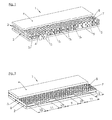
- Fig. 2
- eine Ausführungsform der erfindungsgemäßen Matratze in der Darstellung wie in
Fig. 1 , bei der die Profilierung der hier durchgängigen Federelement-Zwischenschicht in Zonen unterschiedlich stark ausgeprägt ist; - Fig. 3
- den Querschnitt durch den Abschnitt einer zweischichtigen Matratze, bei der die innenliegende Oberfläche der unteren Schicht profiliert ist;
- Fig. 4
- den Querschnitt durch den Abschnitt einer dreischichtigen Matratze, bei der beide Oberflächen der mittleren Schicht profiliert sind;
- Fig. 5
- den Querschnitt durch den Abschnitt einer vierschichtigen Matratze, bei der je eine Seite der innenliegenden Schichten profiliert ist und die beiden Schichten mit ihren nicht profilierten Seiten aneinander liegen; und
- Fig. 6
- den Querschnitt durch den Abschnitt einer vierschichtigen Matratze, bei der je eine Seite der innenliegenden Schichten profiliert ist und die beiden Schichten mit ihren profilierten Seiten aneinander liegen.
- Fig. 1
- the perspective view of a mattress with two cover layers and an intermediate layer in which the upper cover layer is partially removed, with different foam spring element strips in the intermediate layer, a strip being shown pulled out for ease of illustration;
- Fig. 2
- an embodiment of the mattress according to the invention in the illustration as in
Fig. 1 in which the profiling of the here intervening spring element intermediate layer is pronounced differently in zones; - Fig. 3
- the cross-section through the portion of a two-layered mattress, wherein the inner surface of the lower layer is profiled;
- Fig. 4
- the cross section through the portion of a three-layered mattress, in which both surfaces of the middle layer are profiled;
- Fig. 5
- the cross section through the portion of a four-layered mattress, wherein each one side of the inner layers is profiled and the two layers with their non-profiled sides to each other; and
- Fig. 6
- the cross section through the section of a four-layer mattress, wherein each one side of the inner layers is profiled and the two layers lie with their profiled sides together.
Wie aus
Zur Reduzierung der zu hohen punktuellen Körperdruckbelastung des Nutzers sind die Oberflächen der Federelementstränge 5x mit einer Vielzahl aufrecht stehender Federelemente 6 mit einer plateauförmigen Oberfläche 7 strukturiert, welche hier bevorzugt einen im Wesentlichen kreisförmigen, runden Querschnitt aufweisen, was zu einer zylindrischen Form der Federelemente 6 führt.
Die Federelementstränge 5x können untereinander wie auch mit der Deck- und der Unterschicht der Matratze durch Klebung verbunden sein, sie können aber auch nur lose aneinandergereiht sein und werden in diesem Fall nur durch die äußeren Schichten und/oder den Matratzenbezug gehalten.How out
To reduce the selective to high body pressure load of the user, the surfaces of the spring element strands are 5 x structured with a plurality of
The spring element strands 5 x may be connected to each other as well as with the top and bottom layer of the mattress by gluing, but they can also only be strung together loosely and are held in this case only by the outer layers and / or the mattress cover.
Die
In den
Die
In der
Die
Der gleiche Aufbau ergibt sich im Übrigen, wenn zwei einzelne Matratzen 12 wie in
Alle Ausführungsformen sind beispielhaft zu verstehen, eine Vielfalt unterschiedlicher Schichtkombinationen und auch mehrerer Schichten, sowie auch in Verbindung mit nicht konturierten, kompakten Zwischenschichten sind umsetzbar.
Es versteht sich, dass die Erfindung nicht auf ein konkretes der Ausführungsbeispiele reduziert ist, sondern im Rahmen der Offenbarung vielfach variabel ist.
Die Erfindung beschränkt sich auch nicht auf die wie in den Figuren dargestellten glatten äußeren Oberflächen der Deck- und/oder der Unterschicht der Matratze, sondern es sind diese oder auch nur eine der Oberflächen in der Praxis üblicherweise profiliert oder mit einer ähnlichen oder auch gleichen Struktur versehen, wie die einer innenliegenden Oberfläche.
Des Weiteren bieten sich zusätzliche, geläufige Bearbeitungsschritte der einzelnen Schichten vor oder nach dem Bearbeitungsvorgang zur Strukturerstellung an, wodurch der Matratze weitere, für ihre Benutzung wichtige Merkmale erteilt werden können. So kann beispielsweise einer oder auch mehreren Schaumstoffplatten in einem Konturschnitt auf einer oder beiden ihrer Oberflächen eine wellige Form gegeben werden, durch die zwischen einzelnen Zwischenschichten und/oder auch zwischen Deckschicht und/oder Unterschicht und einer oder mehrerer Zwischenschicht/en der Matratze Entlüftungskanäle gebildet werden, die den Abtransport von Feuchtigkeit aus der Matratze zusätzlich erleichtern.
Die erfindungsgemäße Strukturierung muss sich nicht über alle Längsbereiche der Matratze erstrecken, sondern kann auch nur in bestimmten Bereichen derselben Einsatz finden. So kann sie beispielsweise nur im Schulterbereich und im Beckenbereich eingesetzt werden, während die Bereiche des Kopfes, der Lenden und der Beine keine Strukturen innenliegender Schichtoberflächen aufweisen.All embodiments are to be understood by way of example, a variety of different layer combinations and also several layers, as well as in connection with non-contoured, compact intermediate layers can be implemented.
It is understood that the invention is not reduced to a specific one of the exemplary embodiments, but is often variable within the scope of the disclosure.
The invention is not limited to the smooth outer surfaces of the cover and / or the lower layer of the mattress as shown in the figures, but these or even only one of the surfaces in practice usually profiled or with a similar or the same structure provided, such as an interior surface.
Furthermore, provide additional, common processing steps of the individual layers before or after the machining process for structure creation, whereby the mattress can be issued more important for their use features. Thus, for example, one or more foam plates can be given a wavy shape in one contour cut on one or both of their surfaces, through which ventilation channels are formed between individual intermediate layers and / or between cover layer and / or lower layer and one or more intermediate layer / s of the mattress , which additionally facilitate the removal of moisture from the mattress.
The structuring according to the invention does not have to extend over all longitudinal areas of the mattress, but can also find use only in certain areas. For example, it can only be used in the shoulder area and in the pelvic area, while the areas of the head, the loins and the legs have no structures of internal layer surfaces.
- 11
- Matratze (mit Indices)Mattress (with indexes)
- 22
- Unterschicht (mit Indices)Lower layer (with indices)
- 33
- Zwischenschicht (mit Indices)Intermediate layer (with indices)
- 44
- Deckschichttopcoat
- 55
- Federelementstrang (mit Indices)Spring element strand (with indices)
- 66
- aufrecht stehendes Federelementupright spring element
- 77
- plateauförmige Oberflächeplateau-shaped surface
- 88th
- Kanal zwischen den FederelementenChannel between the spring elements
- 99
- mittige Zone mit mittlerer Stützwirkungcentral zone with medium support
- 1010
-
Zone mit gegenüber Zone 9 verstärkter StützwirkungZone with reinforced support in relation to
zone 9 - 1111
-
Zone mit gegenüber Zone 9 verminderter StützwirkungZone with reduced support compared to
zone 9 - 1212
- Randzoneborder zone
Claims (10)
Applications Claiming Priority (1)
| Application Number | Priority Date | Filing Date | Title |
|---|---|---|---|
| DE102013004414.6A DE102013004414B4 (en) | 2013-03-15 | 2013-03-15 | Multi-layer padding with zoned and ventilated middle layer and method for its production |
Publications (2)
| Publication Number | Publication Date |
|---|---|
| EP2777437A1 true EP2777437A1 (en) | 2014-09-17 |
| EP2777437B1 EP2777437B1 (en) | 2016-05-11 |
Family
ID=50272266
Family Applications (1)
| Application Number | Title | Priority Date | Filing Date |
|---|---|---|---|
| EP14000843.4A Active EP2777437B1 (en) | 2013-03-15 | 2014-03-10 | Multilayer upholstery with zoned and ventilated middle layer and method for producing the same |
Country Status (2)
| Country | Link |
|---|---|
| EP (1) | EP2777437B1 (en) |
| DE (1) | DE102013004414B4 (en) |
Cited By (1)
| Publication number | Priority date | Publication date | Assignee | Title |
|---|---|---|---|---|
| EP3130257A1 (en) * | 2015-08-13 | 2017-02-15 | Industrias Lecos S.r.l. | A rest mattress structure |
Families Citing this family (1)
| Publication number | Priority date | Publication date | Assignee | Title |
|---|---|---|---|---|
| CN112021861B (en) * | 2020-06-29 | 2023-02-10 | 际诺思股份公司 | Mattress and method for manufacturing same |
Citations (14)
| Publication number | Priority date | Publication date | Assignee | Title |
|---|---|---|---|---|
| US5111542A (en) * | 1988-04-04 | 1992-05-12 | Farley David L | Anatomically conformable foam support pad |
| DE3424942C2 (en) | 1984-07-06 | 1993-12-16 | Diamona Hermann Koch Kg Fabrik | mattress |
| EP0642894A1 (en) | 1993-09-15 | 1995-03-15 | Foamex L.P. | Three dimensional surface shaping of synthetic foam pads by continuous rotary process |
| DE19521910C1 (en) | 1995-05-06 | 1996-09-26 | Huelsta Werke Huels Kg | Cushion element made from foam material |
| DE29621190U1 (en) * | 1996-12-06 | 1997-02-06 | Diamona Hermann Koch Gmbh & Co | mattress |
| EP0632702B1 (en) | 1993-01-09 | 1998-07-01 | Lück GmbH & Co. KG | Upholstered element |
| US6782575B1 (en) * | 2003-09-05 | 2004-08-31 | Steven J. Antinori | Mattress core and mattress providing pressure relief and minimizing body pressure |
| DE202005015047U1 (en) | 2005-06-20 | 2006-03-16 | Liao, Hsiu-Chen | combination mattress |
| DE102004046517A1 (en) | 2004-09-23 | 2006-03-30 | Schwenk, Hans Ulrich, Dipl.-Ing. | Method for manufacture of cushion element of foam with grooves in surface entails producing parts of foam block with deeper grooves in at least one region by deeper pressing into forming grooves of groove roller |
| US7334280B1 (en) * | 2006-08-11 | 2008-02-26 | Swartzburg Rick T | Ventilated mattress and method |
| DE202008001757U1 (en) | 2008-01-01 | 2008-04-10 | Schwenk, Hans Ulrich, Dipl.-Ing. | Mattress for reclining furniture |
| DE102006025136B4 (en) | 2006-05-30 | 2008-07-10 | Metzeler Schaum Gmbh | Upholstery element, in particular a mattress, and spring element unit for such |
| DE102012004962A1 (en) | 2011-03-15 | 2012-09-20 | Hans Ulrich Schwenk | Foam mattress |
| DE102007051232C5 (en) | 2007-10-10 | 2012-11-22 | diamona Hermann Koch GmbH & Co. KG Fabrik für Wohn- und Schlafkomfort | mattress |
Family Cites Families (3)
| Publication number | Priority date | Publication date | Assignee | Title |
|---|---|---|---|---|
| DE3637448C2 (en) * | 1985-10-28 | 1995-05-24 | Lieberknecht A | Mattress with spring core or upholstered core |
| US4901387A (en) * | 1988-03-21 | 1990-02-20 | Luke John K | Mattress overlay with individual foam springs |
| DE102010014664B4 (en) * | 2010-04-12 | 2015-02-12 | Metzeler Schaum Gmbh | Upholstery element, in particular a mattress |
-
2013
- 2013-03-15 DE DE102013004414.6A patent/DE102013004414B4/en not_active Expired - Fee Related
-
2014
- 2014-03-10 EP EP14000843.4A patent/EP2777437B1/en active Active
Patent Citations (14)
| Publication number | Priority date | Publication date | Assignee | Title |
|---|---|---|---|---|
| DE3424942C2 (en) | 1984-07-06 | 1993-12-16 | Diamona Hermann Koch Kg Fabrik | mattress |
| US5111542A (en) * | 1988-04-04 | 1992-05-12 | Farley David L | Anatomically conformable foam support pad |
| EP0632702B1 (en) | 1993-01-09 | 1998-07-01 | Lück GmbH & Co. KG | Upholstered element |
| EP0642894A1 (en) | 1993-09-15 | 1995-03-15 | Foamex L.P. | Three dimensional surface shaping of synthetic foam pads by continuous rotary process |
| DE19521910C1 (en) | 1995-05-06 | 1996-09-26 | Huelsta Werke Huels Kg | Cushion element made from foam material |
| DE29621190U1 (en) * | 1996-12-06 | 1997-02-06 | Diamona Hermann Koch Gmbh & Co | mattress |
| US6782575B1 (en) * | 2003-09-05 | 2004-08-31 | Steven J. Antinori | Mattress core and mattress providing pressure relief and minimizing body pressure |
| DE102004046517A1 (en) | 2004-09-23 | 2006-03-30 | Schwenk, Hans Ulrich, Dipl.-Ing. | Method for manufacture of cushion element of foam with grooves in surface entails producing parts of foam block with deeper grooves in at least one region by deeper pressing into forming grooves of groove roller |
| DE202005015047U1 (en) | 2005-06-20 | 2006-03-16 | Liao, Hsiu-Chen | combination mattress |
| DE102006025136B4 (en) | 2006-05-30 | 2008-07-10 | Metzeler Schaum Gmbh | Upholstery element, in particular a mattress, and spring element unit for such |
| US7334280B1 (en) * | 2006-08-11 | 2008-02-26 | Swartzburg Rick T | Ventilated mattress and method |
| DE102007051232C5 (en) | 2007-10-10 | 2012-11-22 | diamona Hermann Koch GmbH & Co. KG Fabrik für Wohn- und Schlafkomfort | mattress |
| DE202008001757U1 (en) | 2008-01-01 | 2008-04-10 | Schwenk, Hans Ulrich, Dipl.-Ing. | Mattress for reclining furniture |
| DE102012004962A1 (en) | 2011-03-15 | 2012-09-20 | Hans Ulrich Schwenk | Foam mattress |
Cited By (1)
| Publication number | Priority date | Publication date | Assignee | Title |
|---|---|---|---|---|
| EP3130257A1 (en) * | 2015-08-13 | 2017-02-15 | Industrias Lecos S.r.l. | A rest mattress structure |
Also Published As
| Publication number | Publication date |
|---|---|
| DE102013004414A1 (en) | 2014-09-18 |
| EP2777437B1 (en) | 2016-05-11 |
| DE102013004414B4 (en) | 2017-08-03 |
Similar Documents
| Publication | Publication Date | Title |
|---|---|---|
| EP1068094B1 (en) | Seat cushion for vehicle seat | |
| EP2050364A2 (en) | Foamed distancer for filling mattress cores, upholstery and cushions | |
| DE60204973T2 (en) | METHOD FOR PRODUCING AN INTERNAL BLADE FOR AN ELECTRIC SHAVING APPARATUS | |
| WO2008062263A1 (en) | Component made of a flat material and method for the production thereof | |
| WO2016206795A1 (en) | Counter-die and method for creasing paper, cardboard or corrugated cardboard | |
| DE202013105976U1 (en) | Support layer for mattresses and / or pillows, mattresses and / or pillows with the support layer | |
| DE102006052555B3 (en) | Production of wood composite panels with structured surface comprises applying flexible coating to support panel, cutting into strips, embossing coated surface, profiling long edges, cutting into panels and profiling top and bottom edges | |
| EP2777437B1 (en) | Multilayer upholstery with zoned and ventilated middle layer and method for producing the same | |
| EP0342352A2 (en) | Method of making foam upholstery | |
| DE102014005190B4 (en) | Interior trim part with a flat heating element and method for its production | |
| DE3043917C2 (en) | Method of manufacturing a shoulder pad | |
| WO2009013280A1 (en) | Abrasive material for treating surfaces | |
| DE60216476T2 (en) | METHOD FOR PRODUCING A FILLING ELEMENT | |
| DE19600435A1 (en) | Mattress comprising two superimposed foam sheets | |
| DE102017117559B4 (en) | Mattress core and mattress core layer | |
| EP3531875B1 (en) | Spring element, spring and mattress | |
| DE102004046517B4 (en) | Method for producing a cushioning element made of foam, device for carrying out the method and padding element made of foam | |
| DE202008001757U1 (en) | Mattress for reclining furniture | |
| EP3456531A1 (en) | Reinforcement structure made of flat, cellular base material and method for fabricating a three dimensional deformable, flat reinforcing structure | |
| DE602004005255T2 (en) | Perforating device and method for the layer of a mattress | |
| DE10150494B4 (en) | Method for producing a cushion body made of foam and upholstery body according to this method | |
| DE3120875C2 (en) | Molded insert for a brassiere and method of manufacturing the molded insert | |
| DE69820826T2 (en) | A method of manufacturing a body support member and such a body support member | |
| DE102005006164B4 (en) | Sound-absorbing element and method of making the same | |
| DE8209206U1 (en) | CHAIR SEAT, BACKREST OR SEAT SHELL MADE OF CARDBOARD OR CARDBOARD |
Legal Events
| Date | Code | Title | Description |
|---|---|---|---|
| PUAI | Public reference made under article 153(3) epc to a published international application that has entered the european phase |
Free format text: ORIGINAL CODE: 0009012 |
|
| 17P | Request for examination filed |
Effective date: 20140310 |
|
| AK | Designated contracting states |
Kind code of ref document: A1 Designated state(s): AL AT BE BG CH CY CZ DE DK EE ES FI FR GB GR HR HU IE IS IT LI LT LU LV MC MK MT NL NO PL PT RO RS SE SI SK SM TR |
|
| R17P | Request for examination filed (corrected) |
Effective date: 20150209 |
|
| RBV | Designated contracting states (corrected) |
Designated state(s): AL AT BE BG CH CY CZ DE DK EE ES FI FR GB GR HR HU IE IS IT LI LT LU LV MC MK MT NL NO PL PT RO RS SE SI SK SM TR |
|
| 17Q | First examination report despatched |
Effective date: 20150507 |
|
| GRAP | Despatch of communication of intention to grant a patent |
Free format text: ORIGINAL CODE: EPIDOSNIGR1 |
|
| INTG | Intention to grant announced |
Effective date: 20150930 |
|
| GRAS | Grant fee paid |
Free format text: ORIGINAL CODE: EPIDOSNIGR3 |
|
| GRAA | (expected) grant |
Free format text: ORIGINAL CODE: 0009210 |
|
| AK | Designated contracting states |
Kind code of ref document: B1 Designated state(s): AL AT BE BG CH CY CZ DE DK EE ES FI FR GB GR HR HU IE IS IT LI LT LU LV MC MK MT NL NO PL PT RO RS SE SI SK SM TR |
|
| REG | Reference to a national code |
Ref country code: GB Ref legal event code: FG4D Free format text: NOT ENGLISH |
|
| REG | Reference to a national code |
Ref country code: CH Ref legal event code: EP |
|
| REG | Reference to a national code |
Ref country code: AT Ref legal event code: REF Ref document number: 797938 Country of ref document: AT Kind code of ref document: T Effective date: 20160515 |
|
| REG | Reference to a national code |
Ref country code: CH Ref legal event code: NV Representative=s name: RENTSCH PARTNER AG, CH |
|
| REG | Reference to a national code |
Ref country code: IE Ref legal event code: FG4D Free format text: LANGUAGE OF EP DOCUMENT: GERMAN |
|
| REG | Reference to a national code |
Ref country code: DE Ref legal event code: R096 Ref document number: 502014000746 Country of ref document: DE |
|
| REG | Reference to a national code |
Ref country code: LT Ref legal event code: MG4D |
|
| REG | Reference to a national code |
Ref country code: NL Ref legal event code: MP Effective date: 20160511 |
|
| PG25 | Lapsed in a contracting state [announced via postgrant information from national office to epo] |
Ref country code: LT Free format text: LAPSE BECAUSE OF FAILURE TO SUBMIT A TRANSLATION OF THE DESCRIPTION OR TO PAY THE FEE WITHIN THE PRESCRIBED TIME-LIMIT Effective date: 20160511 Ref country code: FI Free format text: LAPSE BECAUSE OF FAILURE TO SUBMIT A TRANSLATION OF THE DESCRIPTION OR TO PAY THE FEE WITHIN THE PRESCRIBED TIME-LIMIT Effective date: 20160511 Ref country code: NL Free format text: LAPSE BECAUSE OF FAILURE TO SUBMIT A TRANSLATION OF THE DESCRIPTION OR TO PAY THE FEE WITHIN THE PRESCRIBED TIME-LIMIT Effective date: 20160511 Ref country code: NO Free format text: LAPSE BECAUSE OF FAILURE TO SUBMIT A TRANSLATION OF THE DESCRIPTION OR TO PAY THE FEE WITHIN THE PRESCRIBED TIME-LIMIT Effective date: 20160811 |
|
| PG25 | Lapsed in a contracting state [announced via postgrant information from national office to epo] |
Ref country code: GR Free format text: LAPSE BECAUSE OF FAILURE TO SUBMIT A TRANSLATION OF THE DESCRIPTION OR TO PAY THE FEE WITHIN THE PRESCRIBED TIME-LIMIT Effective date: 20160812 Ref country code: LV Free format text: LAPSE BECAUSE OF FAILURE TO SUBMIT A TRANSLATION OF THE DESCRIPTION OR TO PAY THE FEE WITHIN THE PRESCRIBED TIME-LIMIT Effective date: 20160511 Ref country code: HR Free format text: LAPSE BECAUSE OF FAILURE TO SUBMIT A TRANSLATION OF THE DESCRIPTION OR TO PAY THE FEE WITHIN THE PRESCRIBED TIME-LIMIT Effective date: 20160511 Ref country code: SE Free format text: LAPSE BECAUSE OF FAILURE TO SUBMIT A TRANSLATION OF THE DESCRIPTION OR TO PAY THE FEE WITHIN THE PRESCRIBED TIME-LIMIT Effective date: 20160511 Ref country code: PT Free format text: LAPSE BECAUSE OF FAILURE TO SUBMIT A TRANSLATION OF THE DESCRIPTION OR TO PAY THE FEE WITHIN THE PRESCRIBED TIME-LIMIT Effective date: 20160912 Ref country code: RS Free format text: LAPSE BECAUSE OF FAILURE TO SUBMIT A TRANSLATION OF THE DESCRIPTION OR TO PAY THE FEE WITHIN THE PRESCRIBED TIME-LIMIT Effective date: 20160511 Ref country code: ES Free format text: LAPSE BECAUSE OF FAILURE TO SUBMIT A TRANSLATION OF THE DESCRIPTION OR TO PAY THE FEE WITHIN THE PRESCRIBED TIME-LIMIT Effective date: 20160511 |
|
| PG25 | Lapsed in a contracting state [announced via postgrant information from national office to epo] |
Ref country code: IT Free format text: LAPSE BECAUSE OF FAILURE TO SUBMIT A TRANSLATION OF THE DESCRIPTION OR TO PAY THE FEE WITHIN THE PRESCRIBED TIME-LIMIT Effective date: 20160511 |
|
| PG25 | Lapsed in a contracting state [announced via postgrant information from national office to epo] |
Ref country code: SK Free format text: LAPSE BECAUSE OF FAILURE TO SUBMIT A TRANSLATION OF THE DESCRIPTION OR TO PAY THE FEE WITHIN THE PRESCRIBED TIME-LIMIT Effective date: 20160511 Ref country code: CZ Free format text: LAPSE BECAUSE OF FAILURE TO SUBMIT A TRANSLATION OF THE DESCRIPTION OR TO PAY THE FEE WITHIN THE PRESCRIBED TIME-LIMIT Effective date: 20160511 Ref country code: EE Free format text: LAPSE BECAUSE OF FAILURE TO SUBMIT A TRANSLATION OF THE DESCRIPTION OR TO PAY THE FEE WITHIN THE PRESCRIBED TIME-LIMIT Effective date: 20160511 Ref country code: DK Free format text: LAPSE BECAUSE OF FAILURE TO SUBMIT A TRANSLATION OF THE DESCRIPTION OR TO PAY THE FEE WITHIN THE PRESCRIBED TIME-LIMIT Effective date: 20160511 Ref country code: RO Free format text: LAPSE BECAUSE OF FAILURE TO SUBMIT A TRANSLATION OF THE DESCRIPTION OR TO PAY THE FEE WITHIN THE PRESCRIBED TIME-LIMIT Effective date: 20160511 |
|
| REG | Reference to a national code |
Ref country code: DE Ref legal event code: R097 Ref document number: 502014000746 Country of ref document: DE |
|
| PG25 | Lapsed in a contracting state [announced via postgrant information from national office to epo] |
Ref country code: PL Free format text: LAPSE BECAUSE OF FAILURE TO SUBMIT A TRANSLATION OF THE DESCRIPTION OR TO PAY THE FEE WITHIN THE PRESCRIBED TIME-LIMIT Effective date: 20160511 Ref country code: SM Free format text: LAPSE BECAUSE OF FAILURE TO SUBMIT A TRANSLATION OF THE DESCRIPTION OR TO PAY THE FEE WITHIN THE PRESCRIBED TIME-LIMIT Effective date: 20160511 |
|
| PLBE | No opposition filed within time limit |
Free format text: ORIGINAL CODE: 0009261 |
|
| STAA | Information on the status of an ep patent application or granted ep patent |
Free format text: STATUS: NO OPPOSITION FILED WITHIN TIME LIMIT |
|
| 26N | No opposition filed |
Effective date: 20170214 |
|
| PG25 | Lapsed in a contracting state [announced via postgrant information from national office to epo] |
Ref country code: SI Free format text: LAPSE BECAUSE OF FAILURE TO SUBMIT A TRANSLATION OF THE DESCRIPTION OR TO PAY THE FEE WITHIN THE PRESCRIBED TIME-LIMIT Effective date: 20160511 |
|
| REG | Reference to a national code |
Ref country code: CH Ref legal event code: PCAR Free format text: NEW ADDRESS: BELLERIVESTRASSE 203 POSTFACH, 8034 ZUERICH (CH) |
|
| PG25 | Lapsed in a contracting state [announced via postgrant information from national office to epo] |
Ref country code: MC Free format text: LAPSE BECAUSE OF FAILURE TO SUBMIT A TRANSLATION OF THE DESCRIPTION OR TO PAY THE FEE WITHIN THE PRESCRIBED TIME-LIMIT Effective date: 20160511 |
|
| REG | Reference to a national code |
Ref country code: IE Ref legal event code: MM4A |
|
| REG | Reference to a national code |
Ref country code: FR Ref legal event code: ST Effective date: 20171130 |
|
| PG25 | Lapsed in a contracting state [announced via postgrant information from national office to epo] |
Ref country code: LU Free format text: LAPSE BECAUSE OF NON-PAYMENT OF DUE FEES Effective date: 20170310 Ref country code: FR Free format text: LAPSE BECAUSE OF NON-PAYMENT OF DUE FEES Effective date: 20170331 |
|
| PG25 | Lapsed in a contracting state [announced via postgrant information from national office to epo] |
Ref country code: IE Free format text: LAPSE BECAUSE OF NON-PAYMENT OF DUE FEES Effective date: 20170310 |
|
| REG | Reference to a national code |
Ref country code: BE Ref legal event code: MM Effective date: 20170331 |
|
| PG25 | Lapsed in a contracting state [announced via postgrant information from national office to epo] |
Ref country code: BE Free format text: LAPSE BECAUSE OF NON-PAYMENT OF DUE FEES Effective date: 20170331 |
|
| PG25 | Lapsed in a contracting state [announced via postgrant information from national office to epo] |
Ref country code: MT Free format text: LAPSE BECAUSE OF FAILURE TO SUBMIT A TRANSLATION OF THE DESCRIPTION OR TO PAY THE FEE WITHIN THE PRESCRIBED TIME-LIMIT Effective date: 20160511 |
|
| PG25 | Lapsed in a contracting state [announced via postgrant information from national office to epo] |
Ref country code: AL Free format text: LAPSE BECAUSE OF FAILURE TO SUBMIT A TRANSLATION OF THE DESCRIPTION OR TO PAY THE FEE WITHIN THE PRESCRIBED TIME-LIMIT Effective date: 20160511 |
|
| GBPC | Gb: european patent ceased through non-payment of renewal fee |
Effective date: 20180310 |
|
| PG25 | Lapsed in a contracting state [announced via postgrant information from national office to epo] |
Ref country code: GB Free format text: LAPSE BECAUSE OF NON-PAYMENT OF DUE FEES Effective date: 20180310 |
|
| PG25 | Lapsed in a contracting state [announced via postgrant information from national office to epo] |
Ref country code: HU Free format text: LAPSE BECAUSE OF FAILURE TO SUBMIT A TRANSLATION OF THE DESCRIPTION OR TO PAY THE FEE WITHIN THE PRESCRIBED TIME-LIMIT; INVALID AB INITIO Effective date: 20140310 |
|
| PG25 | Lapsed in a contracting state [announced via postgrant information from national office to epo] |
Ref country code: BG Free format text: LAPSE BECAUSE OF FAILURE TO SUBMIT A TRANSLATION OF THE DESCRIPTION OR TO PAY THE FEE WITHIN THE PRESCRIBED TIME-LIMIT Effective date: 20160511 |
|
| PG25 | Lapsed in a contracting state [announced via postgrant information from national office to epo] |
Ref country code: CY Free format text: LAPSE BECAUSE OF NON-PAYMENT OF DUE FEES Effective date: 20160511 |
|
| PG25 | Lapsed in a contracting state [announced via postgrant information from national office to epo] |
Ref country code: MK Free format text: LAPSE BECAUSE OF FAILURE TO SUBMIT A TRANSLATION OF THE DESCRIPTION OR TO PAY THE FEE WITHIN THE PRESCRIBED TIME-LIMIT Effective date: 20160511 |
|
| PG25 | Lapsed in a contracting state [announced via postgrant information from national office to epo] |
Ref country code: TR Free format text: LAPSE BECAUSE OF FAILURE TO SUBMIT A TRANSLATION OF THE DESCRIPTION OR TO PAY THE FEE WITHIN THE PRESCRIBED TIME-LIMIT Effective date: 20160511 |
|
| PGFP | Annual fee paid to national office [announced via postgrant information from national office to epo] |
Ref country code: CH Payment date: 20200325 Year of fee payment: 7 |
|
| PG25 | Lapsed in a contracting state [announced via postgrant information from national office to epo] |
Ref country code: IS Free format text: LAPSE BECAUSE OF FAILURE TO SUBMIT A TRANSLATION OF THE DESCRIPTION OR TO PAY THE FEE WITHIN THE PRESCRIBED TIME-LIMIT Effective date: 20160911 |
|
| REG | Reference to a national code |
Ref country code: DE Ref legal event code: R082 Ref document number: 502014000746 Country of ref document: DE Representative=s name: MUELLER HOFFMANN & PARTNER PATENTANWAELTE MBB, DE Ref country code: DE Ref legal event code: R081 Ref document number: 502014000746 Country of ref document: DE Owner name: GROLL GMBH & CO. KG, DE Free format text: FORMER OWNER: SCHWENK, HANS ULRICH, DIPL.-ING., 72766 REUTLINGEN, DE |
|
| REG | Reference to a national code |
Ref country code: AT Ref legal event code: PC Ref document number: 797938 Country of ref document: AT Kind code of ref document: T Owner name: GROLL GMBH & CO. KG, DE Effective date: 20210215 |
|
| REG | Reference to a national code |
Ref country code: CH Ref legal event code: PL |
|
| PG25 | Lapsed in a contracting state [announced via postgrant information from national office to epo] |
Ref country code: CH Free format text: LAPSE BECAUSE OF NON-PAYMENT OF DUE FEES Effective date: 20210331 Ref country code: LI Free format text: LAPSE BECAUSE OF NON-PAYMENT OF DUE FEES Effective date: 20210331 |
|
| PGFP | Annual fee paid to national office [announced via postgrant information from national office to epo] |
Ref country code: AT Payment date: 20230317 Year of fee payment: 10 |
|
| PGFP | Annual fee paid to national office [announced via postgrant information from national office to epo] |
Ref country code: DE Payment date: 20230329 Year of fee payment: 10 |