EP2802160B1 - Hearing system having improved high frequency response - Google Patents
Hearing system having improved high frequency response Download PDFInfo
- Publication number
- EP2802160B1 EP2802160B1 EP14179881.9A EP14179881A EP2802160B1 EP 2802160 B1 EP2802160 B1 EP 2802160B1 EP 14179881 A EP14179881 A EP 14179881A EP 2802160 B1 EP2802160 B1 EP 2802160B1
- Authority
- EP
- European Patent Office
- Prior art keywords
- transmitter
- transducer
- sound
- hearing
- hearing system
- Prior art date
- Legal status (The legal status is an assumption and is not a legal conclusion. Google has not performed a legal analysis and makes no representation as to the accuracy of the status listed.)
- Active
Links
- 230000013707 sensory perception of sound Effects 0.000 title claims description 88
- 230000004044 response Effects 0.000 title claims description 9
- 210000000613 ear canal Anatomy 0.000 claims description 72
- 210000003454 tympanic membrane Anatomy 0.000 claims description 63
- 230000004807 localization Effects 0.000 claims description 23
- 210000000959 ear middle Anatomy 0.000 claims description 19
- 238000000034 method Methods 0.000 claims description 15
- 210000003027 ear inner Anatomy 0.000 claims description 11
- 230000005540 biological transmission Effects 0.000 claims description 10
- 239000012530 fluid Substances 0.000 claims description 6
- 230000003287 optical effect Effects 0.000 claims description 4
- 230000005236 sound signal Effects 0.000 claims description 4
- 238000001914 filtration Methods 0.000 claims description 3
- 230000001413 cellular effect Effects 0.000 claims description 2
- 238000002604 ultrasonography Methods 0.000 claims description 2
- 238000009738 saturating Methods 0.000 claims 1
- 241000878128 Malleus Species 0.000 description 11
- 210000002331 malleus Anatomy 0.000 description 11
- 230000008447 perception Effects 0.000 description 8
- 210000001664 manubrium Anatomy 0.000 description 7
- 230000008901 benefit Effects 0.000 description 6
- 210000000988 bone and bone Anatomy 0.000 description 6
- 210000003477 cochlea Anatomy 0.000 description 6
- 230000005672 electromagnetic field Effects 0.000 description 6
- 230000006872 improvement Effects 0.000 description 6
- 238000012545 processing Methods 0.000 description 6
- 210000001050 stape Anatomy 0.000 description 6
- 208000032041 Hearing impaired Diseases 0.000 description 5
- 210000002768 hair cell Anatomy 0.000 description 5
- 230000003321 amplification Effects 0.000 description 4
- 230000001419 dependent effect Effects 0.000 description 4
- 210000000883 ear external Anatomy 0.000 description 4
- 210000000067 inner hair cell Anatomy 0.000 description 4
- 230000033001 locomotion Effects 0.000 description 4
- 238000003199 nucleic acid amplification method Methods 0.000 description 4
- 238000004321 preservation Methods 0.000 description 4
- 230000008569 process Effects 0.000 description 4
- 230000002829 reductive effect Effects 0.000 description 4
- 230000003595 spectral effect Effects 0.000 description 4
- 230000026683 transduction Effects 0.000 description 4
- 238000010361 transduction Methods 0.000 description 4
- 230000000712 assembly Effects 0.000 description 3
- 238000000429 assembly Methods 0.000 description 3
- 210000000721 basilar membrane Anatomy 0.000 description 3
- 230000002301 combined effect Effects 0.000 description 3
- 210000005069 ears Anatomy 0.000 description 3
- 230000010370 hearing loss Effects 0.000 description 3
- 231100000888 hearing loss Toxicity 0.000 description 3
- 208000016354 hearing loss disease Diseases 0.000 description 3
- 230000001965 increasing effect Effects 0.000 description 3
- 210000001785 incus Anatomy 0.000 description 3
- 230000007246 mechanism Effects 0.000 description 3
- 230000001537 neural effect Effects 0.000 description 3
- 230000009467 reduction Effects 0.000 description 3
- 238000005204 segregation Methods 0.000 description 3
- 206010011878 Deafness Diseases 0.000 description 2
- 241000282326 Felis catus Species 0.000 description 2
- 208000006735 Periostitis Diseases 0.000 description 2
- 208000009966 Sensorineural Hearing Loss Diseases 0.000 description 2
- 210000004027 cell Anatomy 0.000 description 2
- 230000009956 central mechanism Effects 0.000 description 2
- 238000004891 communication Methods 0.000 description 2
- 230000006835 compression Effects 0.000 description 2
- 238000007906 compression Methods 0.000 description 2
- 230000008878 coupling Effects 0.000 description 2
- 238000010168 coupling process Methods 0.000 description 2
- 238000005859 coupling reaction Methods 0.000 description 2
- 230000003247 decreasing effect Effects 0.000 description 2
- 230000006870 function Effects 0.000 description 2
- 210000003128 head Anatomy 0.000 description 2
- 239000007943 implant Substances 0.000 description 2
- 239000000463 material Substances 0.000 description 2
- 230000037361 pathway Effects 0.000 description 2
- 210000003460 periosteum Anatomy 0.000 description 2
- 206010011891 Deafness neurosensory Diseases 0.000 description 1
- 208000003098 Ganglion Cysts Diseases 0.000 description 1
- 241000282412 Homo Species 0.000 description 1
- 208000005400 Synovial Cyst Diseases 0.000 description 1
- RTAQQCXQSZGOHL-UHFFFAOYSA-N Titanium Chemical compound [Ti] RTAQQCXQSZGOHL-UHFFFAOYSA-N 0.000 description 1
- 230000009286 beneficial effect Effects 0.000 description 1
- 239000000560 biocompatible material Substances 0.000 description 1
- 230000000903 blocking effect Effects 0.000 description 1
- 238000009530 blood pressure measurement Methods 0.000 description 1
- 210000004556 brain Anatomy 0.000 description 1
- 210000000860 cochlear nerve Anatomy 0.000 description 1
- 210000001787 dendrite Anatomy 0.000 description 1
- 238000013461 design Methods 0.000 description 1
- 238000006073 displacement reaction Methods 0.000 description 1
- 230000000694 effects Effects 0.000 description 1
- 230000003028 elevating effect Effects 0.000 description 1
- 210000000981 epithelium Anatomy 0.000 description 1
- 230000001771 impaired effect Effects 0.000 description 1
- 230000002452 interceptive effect Effects 0.000 description 1
- 210000003127 knee Anatomy 0.000 description 1
- 230000000670 limiting effect Effects 0.000 description 1
- 238000005259 measurement Methods 0.000 description 1
- 239000002480 mineral oil Substances 0.000 description 1
- 235000010446 mineral oil Nutrition 0.000 description 1
- 238000012986 modification Methods 0.000 description 1
- 230000004048 modification Effects 0.000 description 1
- 230000010004 neural pathway Effects 0.000 description 1
- 210000000118 neural pathway Anatomy 0.000 description 1
- 210000002985 organ of corti Anatomy 0.000 description 1
- 230000010355 oscillation Effects 0.000 description 1
- 230000035699 permeability Effects 0.000 description 1
- 230000007115 recruitment Effects 0.000 description 1
- 230000002441 reversible effect Effects 0.000 description 1
- 229920006395 saturated elastomer Polymers 0.000 description 1
- 230000035807 sensation Effects 0.000 description 1
- 230000001953 sensory effect Effects 0.000 description 1
- 238000004088 simulation Methods 0.000 description 1
- 238000001228 spectrum Methods 0.000 description 1
- 229910001220 stainless steel Inorganic materials 0.000 description 1
- 239000010935 stainless steel Substances 0.000 description 1
- 230000001629 suppression Effects 0.000 description 1
- 210000003582 temporal bone Anatomy 0.000 description 1
- 210000003478 temporal lobe Anatomy 0.000 description 1
- 229910052719 titanium Inorganic materials 0.000 description 1
- 239000010936 titanium Substances 0.000 description 1
- 238000012546 transfer Methods 0.000 description 1
- 238000013022 venting Methods 0.000 description 1
- 239000000080 wetting agent Substances 0.000 description 1
- 229910000859 α-Fe Inorganic materials 0.000 description 1
Images


Classifications
-
- H—ELECTRICITY
- H04—ELECTRIC COMMUNICATION TECHNIQUE
- H04R—LOUDSPEAKERS, MICROPHONES, GRAMOPHONE PICK-UPS OR LIKE ACOUSTIC ELECTROMECHANICAL TRANSDUCERS; DEAF-AID SETS; PUBLIC ADDRESS SYSTEMS
- H04R25/00—Deaf-aid sets, i.e. electro-acoustic or electro-mechanical hearing aids; Electric tinnitus maskers providing an auditory perception
- H04R25/40—Arrangements for obtaining a desired directivity characteristic
- H04R25/402—Arrangements for obtaining a desired directivity characteristic using contructional means
-
- H—ELECTRICITY
- H04—ELECTRIC COMMUNICATION TECHNIQUE
- H04R—LOUDSPEAKERS, MICROPHONES, GRAMOPHONE PICK-UPS OR LIKE ACOUSTIC ELECTROMECHANICAL TRANSDUCERS; DEAF-AID SETS; PUBLIC ADDRESS SYSTEMS
- H04R25/00—Deaf-aid sets, i.e. electro-acoustic or electro-mechanical hearing aids; Electric tinnitus maskers providing an auditory perception
- H04R25/45—Prevention of acoustic reaction, i.e. acoustic oscillatory feedback
- H04R25/453—Prevention of acoustic reaction, i.e. acoustic oscillatory feedback electronically
-
- H—ELECTRICITY
- H04—ELECTRIC COMMUNICATION TECHNIQUE
- H04R—LOUDSPEAKERS, MICROPHONES, GRAMOPHONE PICK-UPS OR LIKE ACOUSTIC ELECTROMECHANICAL TRANSDUCERS; DEAF-AID SETS; PUBLIC ADDRESS SYSTEMS
- H04R25/00—Deaf-aid sets, i.e. electro-acoustic or electro-mechanical hearing aids; Electric tinnitus maskers providing an auditory perception
- H04R25/55—Deaf-aid sets, i.e. electro-acoustic or electro-mechanical hearing aids; Electric tinnitus maskers providing an auditory perception using an external connection, either wireless or wired
- H04R25/554—Deaf-aid sets, i.e. electro-acoustic or electro-mechanical hearing aids; Electric tinnitus maskers providing an auditory perception using an external connection, either wireless or wired using a wireless connection, e.g. between microphone and amplifier or using Tcoils
-
- H—ELECTRICITY
- H04—ELECTRIC COMMUNICATION TECHNIQUE
- H04R—LOUDSPEAKERS, MICROPHONES, GRAMOPHONE PICK-UPS OR LIKE ACOUSTIC ELECTROMECHANICAL TRANSDUCERS; DEAF-AID SETS; PUBLIC ADDRESS SYSTEMS
- H04R25/00—Deaf-aid sets, i.e. electro-acoustic or electro-mechanical hearing aids; Electric tinnitus maskers providing an auditory perception
- H04R25/60—Mounting or interconnection of hearing aid parts, e.g. inside tips, housings or to ossicles
- H04R25/604—Mounting or interconnection of hearing aid parts, e.g. inside tips, housings or to ossicles of acoustic or vibrational transducers
- H04R25/606—Mounting or interconnection of hearing aid parts, e.g. inside tips, housings or to ossicles of acoustic or vibrational transducers acting directly on the eardrum, the ossicles or the skull, e.g. mastoid, tooth, maxillary or mandibular bone, or mechanically stimulating the cochlea, e.g. at the oval window
-
- H—ELECTRICITY
- H04—ELECTRIC COMMUNICATION TECHNIQUE
- H04R—LOUDSPEAKERS, MICROPHONES, GRAMOPHONE PICK-UPS OR LIKE ACOUSTIC ELECTROMECHANICAL TRANSDUCERS; DEAF-AID SETS; PUBLIC ADDRESS SYSTEMS
- H04R3/00—Circuits for transducers, loudspeakers or microphones
- H04R3/04—Circuits for transducers, loudspeakers or microphones for correcting frequency response
-
- H—ELECTRICITY
- H04—ELECTRIC COMMUNICATION TECHNIQUE
- H04R—LOUDSPEAKERS, MICROPHONES, GRAMOPHONE PICK-UPS OR LIKE ACOUSTIC ELECTROMECHANICAL TRANSDUCERS; DEAF-AID SETS; PUBLIC ADDRESS SYSTEMS
- H04R23/00—Transducers other than those covered by groups H04R9/00 - H04R21/00
- H04R23/008—Transducers other than those covered by groups H04R9/00 - H04R21/00 using optical signals for detecting or generating sound
-
- H—ELECTRICITY
- H04—ELECTRIC COMMUNICATION TECHNIQUE
- H04R—LOUDSPEAKERS, MICROPHONES, GRAMOPHONE PICK-UPS OR LIKE ACOUSTIC ELECTROMECHANICAL TRANSDUCERS; DEAF-AID SETS; PUBLIC ADDRESS SYSTEMS
- H04R2460/00—Details of hearing devices, i.e. of ear- or headphones covered by H04R1/10 or H04R5/033 but not provided for in any of their subgroups, or of hearing aids covered by H04R25/00 but not provided for in any of its subgroups
- H04R2460/09—Non-occlusive ear tips, i.e. leaving the ear canal open, for both custom and non-custom tips
-
- H—ELECTRICITY
- H04—ELECTRIC COMMUNICATION TECHNIQUE
- H04R—LOUDSPEAKERS, MICROPHONES, GRAMOPHONE PICK-UPS OR LIKE ACOUSTIC ELECTROMECHANICAL TRANSDUCERS; DEAF-AID SETS; PUBLIC ADDRESS SYSTEMS
- H04R2460/00—Details of hearing devices, i.e. of ear- or headphones covered by H04R1/10 or H04R5/033 but not provided for in any of their subgroups, or of hearing aids covered by H04R25/00 but not provided for in any of its subgroups
- H04R2460/13—Hearing devices using bone conduction transducers
Definitions
- the present invention relates to hearing systems. More specifically, the present invention relates to hearing systems that have improved high frequency response that improves the speech reception threshold (SRT) and preserves and transmits high frequency spatial localization cues to the middle or inner ear. Such systems may be used to enhance the hearing process with normal or impaired hearing.
- SRT speech reception threshold
- the eardrum to ear canal entrance pressure ratio has a 10dB resonance at about 3.5 kHz (Wiener et al. 1966; Shaw 1974). This is independent of the sound source location in the horizontal plane (Burkhard and Sachs 1975). This ratio is a function of the dimensions and consequent relative acoustic impedance of the eardrum and the ear canal.
- the 10 dB resonance is typically added in most hearing aids after the microphone input because this gain is not spatially dependent.
- HRTFs Head related transfer functions
- Another factor that determines the measured HRTF is the opening of the ear canal itself. It is conceivable that a device in the ear canal that partially blocks it and thus will alter HRTFs, can eliminate directionally dependent pinna cues. Burkhard and Sachs (1975) have shown that when the canal is blocked, spatially dependent vertical localization cues are modified but nevertheless present. Some relearning of the new cues maybe required to obtain benefit from the high frequency cues. Hoffman et al. (1998) showed that this learning takes place over a period of less than 45 days.
- acoustic hearing systems rely on acoustic transducers that produce amplified sound waves which, in turn, impart vibrations to the tympanic membrane or eardrum.
- the telephone earpiece, radio, television and aids for the hearing impaired are all examples of systems that employ acoustic drive mechanisms.
- the telephone earpiece for instance, converts signals transmitted on a wire into vibrational energy in a speaker which generates acoustic energy. This acoustic energy propagates in the ear canal and vibrates the tympanic membrane. These vibrations, at varying frequencies and amplitudes, result in the perception of sound.
- Surgically implanted cochlear implants electrically stimulate the auditory nerve ganglion cells or dendrites in subjects having profound hearing loss.
- Hearing systems that deliver audio information to the ear through electromagnetic transducers are well known. These transducers convert electromagnetic fields, modulated to contain audio information, into vibrations which are imparted to the tympanic membrane or parts of the middle ear.
- the transducer typically a magnet, is subjected to displacement by electromagnetic fields to impart vibrational motion to the portion to which it is attached, thus producing sound perception by the wearer of such an electromagnetically driven system.
- This method of sound perception possesses some advantages over acoustic drive systems in terms of quality, efficiency, and most importantly, significant reduction of "feedback," a problem common to acoustic hearing systems.
- Feedback in acoustic hearing systems occurs when a portion of the acoustic output energy returns or "feeds back" to the input transducer (microphone), thus causing self-sustained oscillation.
- the potential for feedback is generally proportional to the amplification level of the system and, therefore, the output gain of many acoustic drive systems has to be reduced to less than a desirable level to prevent a feedback situation.
- This problem which results in output gain inadequate to compensate for hearing losses in particularly severe cases, continues to be a major problem with acoustic type hearing aids.
- To minimize the feedback to the microphone many acoustic hearing devices close off, or provide minimal venting, to the ear canal.
- occlusion a tunnel-like hearing sensation that is problematic to most hearing aid users.
- Directly driving the eardrum can minimize the feedback because the drive mechanism is mechanical rather than acoustic. Because of the mechanically vibrating eardrum, sound is coupled to the ear canal and wave propagation is supported in the reverse direction. The mechanical to acoustic coupling, however, is not efficient and this inefficiency is exploited in terms of decreased sound in the ear canal resulting in increased system gain.
- US 5,624,376 describes a floating mass transducer for improving hearing.
- the floating mass transducer may be implanted or mounted externally for producing vibrations in a vibratory structure of an ear.
- the floating mass transducer comprises a magnet assembly and a coil secured inside a housing which is fixed to an ossicle of the middle ear.
- the coil is more rigidly secured to the housing than the magnet and the magnet assembly and coil are configured such that alternating electrical current flowing through the coil results in vibration of the magnet assembly and coil relative to one another. Because the coil is more rigidly secured to the housing than the magnet assembly, the vibrations of the coil cause the housing to vibrate and these vibrations are conducted to the oval window of the ear via the ossicles.
- the floating mass transducer may produce vibrations using piezoelectric materials.
- WO 01/50815 describes a canal hearing device with a sub miniature filament assembly which vibrates and directly drives the tympanic membrane.
- the filament assembly is partially supported by the tympanic membrane via capillary adhesion thereto and is dynamically coupled to a stationary vibration force element positioned at a distance from the tympanic membrane within the ear canal.
- the elongated filament assembly is freely moveable within an operable range and is essentially floating with respect to the vibration force element.
- the vibrational filament assembly may comprise a magnetic section which is insertable into the air core of an electromagnet coil.
- the filament assembly is coupled to the tympanic membrane via an articulated tympanic contact coupler.
- Described herein are hearing system and methods that have an improved high frequency response that improves the speech reception threshold and preserves high frequency spatial localization cues to the middle or inner ear.
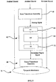
- the input transducer assembly will receive a sound input, typically either ambient sound (in the case of hearing aids for hearing impaired individuals) or an electronic sound signal from a sound producing or receiving device, such as the telephone, a cellular telephone, a radio, a digital audio unit, or any one of a wide variety of other telecommunication and/or entertainment devices.
- the input transducer assembly will send a signal to the transmitter assembly where the transmitter assembly processes the signal from the transducer assembly to produce a processed signal which is modulated in some way, to represent or encode a sound signal which substantially represents the sound input received by the input transducer assembly.
- the exact nature of the processed output signal will be selected to be used by the output transducer assembly to provide both the power and the signal so that the output transducer assembly can produce mechanical vibrations, acoustical output, pressure output, (or other output) which, when properly coupled to a subject's hearing transduction pathway, will induce neural impulses in the subject which will be interpreted by the subject as the original sound input, or at least something reasonably representative of the original sound input.
- the components of a described hearing system are disposed within a shell or housing that is placed within the subject's auditory ear canal.
- the shell has one or more openings on both a first end and a second end so as to provide an open ear canal and to allow ambient sound (such as low and high frequency three dimensional localization cues) to be directly delivered to the tympanic membrane at a high level.
- the openings in the shell do not block the auditory canal and minimize interference with the normal pressurization of the ear.
- the shell houses the input transducer, the transmitter assembly, and a battery. In other embodiments, portions of the transmitter assembly and the battery may be placed behind the ear (BTE), while the input transducer is positioned in the shell.
- the input transducer assembly typically comprises a microphone in the housing that is disposed within the auditory ear canal. Suitable microphones are well known in the hearing aid industry and amply described in the patent and technical literature. The microphones will typically produce an electrical output is received by the transmitter assembly which in turn will produce the processed signal.
- the sound input to the input transducer assembly will typically be electronic, such as from a telephone, cell phone, a portable entertainment unit, or the like. In such cases, the input transducer assembly will typically have a suitable amplifier or other electronic interface which receives the electronic sound input and which produces a filtered electronic output suitable for driving the output transducer assembly.
- the microphone While it is possible to position the microphone behind the pinna, in the temple piece of eyeglasses, or elsewhere on the subject, it is preferable to position the microphone within the ear canal so that the microphone receives and transmits the higher frequency signals that are directed into the ear canal and to thus improve the final SRT.
- the transmitter assembly typically comprises a digital signal processor that processes the electrical signal from the input transducer and delivers a signal to a transmitter element that produces the processed output signal that actuates the output transducer.
- the digital signal processor will often have a filter that has a frequency response bandwidth that is typically greater than 6 kHz, more preferably between about 6 kHz and about 20 kHz, and most preferably between about 7 kHz and 13 kHz.
- Such a transmitter assembly differs from conventional transmitters found in that the higher bandwidth results in greater preservation of spatial localization cues for microphones that are placed at the entrance of the ear canal or within the ear canal.
- the transmitter element that is in communication with the digital signal processor is in the form of a coil that has an open interior and a core sized to fit within the open interior of the coil.
- a power source is coupled to the coil to supply a current to the coil.
- the current delivered to the coil will substantially correspond to the electrical signal processed by the digital signal processor.
- the output transducer assembly may be any component that is able to receive the processed signal from the transmitter assembly.
- the output transducer assembly will typically be configured to couple to some point in the hearing transduction pathway of the subject in order to induce neural impulses which are interpreted as sound by the subject.
- a portion of the output transducer assembly will couple to the tympanic membrane, a bone in the ossicular chain, or directly to the cochlea where it is positioned to vibrate fluid within the cochlea. Specific points of attachment are described in prior U.S. Patent Nos. 5,259,032 ; 5,456,654 ; 6,084,975 ; and 6,629,922 .
- a hearing system that has an input transducer that is positionable within an ear canal of a user to capture ambient sound that enters the ear canal of the user.
- a transmitter assembly receives electrical signals from the input transducer.
- the transmitter assembly comprises a signal processor that has a frequency response bandwidth in a 6.0 kHz to 20 kHz range.
- the transmitter assembly is configured to deliver filtered signals to an output transducer positioned in a middle or inner ear of the user, wherein the filtered signal is representative of the ambient sound received by the input transducer.
- a configuration of the input transducer and transmitter assembly provides an open ear canal that allows ambient sound to directly reach the middle ear of the user.
- a described method comprises positioning an input transducer within an ear canal of a user and transmitting signals from the input transducer that are indicative of ambient sound received by the input transducer to a transmitter assembly.
- the signals are processed (e.g., filtered) at the transmitter assembly with a signal processor that has a filter that has a bandwidth that is larger than about 6.0 kHz.
- the filtered signals are delivered to a middle ear or inner ear of the user.
- the positioning of the input transducer and transmitter assembly provides an open ear canal that allows non-filtered ambient sound to directly reach the middle ear of the user.
- the signal processor has a bandwidth between about 6 kHz and about 20 kHz, so as to allow for preservation and transmission of the high frequency spatial localization cues.
- an electromagnetic transmitter assembly and output transducer While the remaining discussion will focus on the use of an electromagnetic transmitter assembly and output transducer, it should be appreciated that the present invention is not limited to such transmitter assemblies, and various other types of transmitter assemblies may be used.
- the photo-mechanical hearing transduction assembly described in co-pending and commonly owned, U.S. Provisional Patent Application Serial No. 60/618,408, filed October 12, 2004 , entitled “Systems and Methods for Photo-mechanical Hearing Transduction” may be used with the hearing systems of the present invention.
- other transmitter assemblies such as optical transmitters, ultrasound transmitters, infrared transmitters, acoustical transmitters, or fluid pressure transmitters, or the like may take advantage of the principles of the present invention.
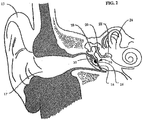
- FIG. 1 there is shown a cross sectional view of an outer ear 10, middle ear 12 and a portion of an inner ear 14.
- the outer ear 10 comprises primarily of the pinna 15 and the auditory ear canal 17.
- the middle ear 12 is bounded by the tympanic membrane (ear drum) 16 on one side, and contains a series of three tiny interconnnected bones: the malleus (hammer) 18; the incus (anvil) 20; and the stapes (stirrup) 22. Collectively, these three bones are known as the ossicles or the ossicular chain.
- the malleus 18 is attached to the tympanic membrane 16 while the stapes 22, the last bone in the ossicular chain, is coupled to the cochlea 24 of the inner ear.
- the fluid pressure results in a traveling wave along the longitudinal axis of the basilar membrane (not shown).
- the organ of Corti sits atop the basilar membrane which contains the sensory epithelium consisting of one row of inner hair cells and three rows of outer hair cells.
- the inner-hair cells (not shown) in the cochlea are stimulated by the movement of the basilar membrane.
- hydraulic pressure displaces the inner ear fluid and mechanical energy in the hair cells is transformed into electrical impulses, which are transmitted to neural pathways and the hearing center of the brain (temporal lobe), resulting in the perception of sound.
- the outer hair cells are believed to amplify and compress the input to the inner hair cells.
- Amplification by a hearing system may fully or partially restore the otherwise normal amplification and compression provided by the outer hair cells.
- a presently preferred coupling point of the output transducer assembly is on the outer surface of the tympanic membrane 16 and is illustrated in FIG. 2 .
- the output transducer assembly 26 comprises a transducer 28 that is placed in contact with an exterior surface of the tympanic membrane 10.
- the transducer 28 generally comprises a high-energy permanent magnet.
- a preferred method of positioning the transducer is to employ a contact transducer assembly that includes transducer 28 and a support assembly 30.
- Support assembly 30 is attached to, or floating on, a portion of the tympanic membrane 16.
- the support assembly is a biocompatible structure with a surface area sufficient to support the transducer 28, and is vibrationally coupled to the tympanic membrane 16.
- the surface of support assembly 30 that is attached to the tympanic membrane substantially conforms to the shape of the corresponding surface of the tympanic membrane, particularly the umbo area 32.
- the support assembly 30 is a conically shaped film in which the transducer is embedded therein.
- the film is releasably contacted with a surface of the tympanic membrane.
- a surface wetting agent such as mineral oil, is preferably used to enhance the ability of support assembly 30 to form a weak but sufficient attachment to the tympanic membrane 16 through surface adhesion.
- One suitable contact transducer assembly is described in U.S. Pat. No. 5,259,032 .
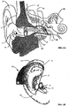
- FIGS. 3A and 3B illustrate alternative embodiments wherein a transducer is placed on the malleus of an individual.
- a transducer magnet 34 is attached to the medial side of the inferior manubrium.
- magnet 34 is encased in titanium or other biocompatible material.
- one method of attaching magnet 34 to the malleus is disclosed in U.S. Patent No.
- magnet 34 is attached to the medial surface of the manubrium 44 of the malleus 18 by making an incision in the posterior periosteum of the lower manubrium, and elevating the periosteum from the manubrium, thus creating a pocket between the lateral surface of the manubrium and the tympanic membrane 10.
- One prong of a stainless steel clip device may be placed into the pocket, with the transducer magnet 34 attached thereto.
- the interior of the clip is of appropriate dimension such that the clip now holds onto the manubrium placing the magnet on its medial surface.
- FIG. 3B illustrates an embodiment wherein clip 36 is secured around the neck of the malleus 18, in between the manubrium and the head 38 of the malleus.
- the clip 36 extends to provide a platform of orienting the transducer magnet 34 toward the tympanic membrane 16 and ear canal 17 such that the transducer magnet 34 is in a substantially optimal position to receive signals from the transmitter assembly.
- FIG. 4A illustrates one preferred embodiment of a hearing system 40.
- the hearing system 40 comprises the transmitter assembly 42 (illustrated with shell 44 cross-sectioned for clarity) that is installed in a right ear canal and oriented with respect to the magnetic transducer 28 on the tympanic membrane 16.
- the transducer 28 is positioned against tympanic membrane 16 at umbo area 32.
- the transducer may also be placed on other acoustic members of the middle ear, including locations on the malleus 18 (shown in FIGS. 3A and 3B ), incus 20, and stapes 22.
- the transducer 28 When placed in the umbo area 32 of the tympanic membrane 16, the transducer 28 will be naturally tilted with respect to the ear canal 17. The degree of tilt will vary from individual to individual, but is typically at about a 60-degree angle with respect to the ear canal.
- the transmitter assembly 42 has a shell 44 configured to mate with the characteristics of the individual's ear canal wall.
- Shell 44 is preferably matched to fit snug in the individual's ear canal so that the transmitter assembly 42 may repeatedly be inserted or removed from the ear canal and still be properly aligned when re-inserted in the individual's ear.
- shell 44 is also configured to support a coil 46 and a core 48 such that the tip of core 48 is positioned at a proper distance and orientation in relation to the transducer 28 when the transmitter assembly 42 is properly installed in the ear canal 17.
- the core 48 generally comprises ferrite, but may be any material with high magnetic permeability.
- coil 46 is wrapped around the circumference of the core 48 along part or all of the length of the core.
- the coil has a sufficient number of rotations to optimally drive an electromagnetic field toward the transducer 28.
- the number of rotations may vary depending on the diameter of the coil, the diameter of the core, the length of the core, and the overall acceptable diameter of the coil and core assembly based on the size of the individual's ear canal.
- the force applied by the magnetic field on the magnet will increase, and therefore increase the efficiency of the system, with an increase in the diameter of the core. These parameters will be constrained, however, by the anatomical limitations of the individual's ear.
- the coil 46 may be wrapped around only a portion of the length of the core, as shown in FIG. 4A , allowing the tip of the core to extend further into the ear canal 17, which generally converges as it reaches the tympanic membrane 16.
- One method for matching the shell 44 to the internal dimensions of the ear canal is to make an impression of the ear canal cavity, including the tympanic membrane. A positive investment is then made from the negative impression. The outer surface of the shell is then formed from the positive investment which replicated the external surface of the impression.
- the coil 46 and core 48 assembly can then be positioned and mounted in the shell 44 according to the desired orientation with respect to the projected placement of the transducer 28, which may be determined from the positive investment of the ear canal and tympanic membrane.
- the transmitter assembly 42 may also incorporate a mounting platform (not shown) with micro-adjustment capability for orienting the coil and core assembly such that the core can be oriented and positioned with respect to the shell and/or the coil.
- a CT, MRI or optical scan may be performed on the individual to generate a 3D model of the ear canal and the tympanic membrane.
- the digital 3D model representation may then be used to form the outside surface of the shell 44 and mount the core and coil.
- transmitter assembly 42 may also comprise a digital signal processing (DSP) unit and other components 50 and a battery 52 that are placed inside shell 44.
- DSP digital signal processing
- the proximal end 53 of the shell 44 is open 54 and has the input transducer (microphone) 56 positioned on the shell so as to directly receive the ambient sound that enters the auditory ear canal 17.
- the open chamber 58 provides access to the shell 44 and transmitter assembly 42 components contained therein.
- a pull line 60 may also be incorporated into the shell 44 so that the transmitter assembly can be readily removed from the ear canal.
- An acoustic opening 62 of the shell allows ambient sound to enter the open chamber 58 of the shell. This allows ambient sound to travel through the open volume 58 along the internal compartment of the transmitter assembly 42 and through one or more openings 64 at the distal end of the shell 44. Thus, ambient sound waves may reach and directly vibrate the tympanic membrane 16 and separately impart vibration on the tympanic membrane.
- This open-channel design provides a number of substantial benefits. First, the open channel 17 minimizes the occlusive effect prevalent in many acoustic hearing systems from blocking the ear canal. Second, the open channel allows the high frequency spatial localization cues to be directly transmitted to the tympanic membrane 17.
- the natural ambient sound entering the ear canal 16 allows the electromagnetically driven effective sound level output to be limited or cut off at a much lower level than with a hearing system that blocks the ear canal 17.
- having a fully open shell preserves the natural pinna diffraction cues of the subject and thus little to no acclimatization, as described by Hoffinan et al. (1998), is required.
- ambient sound entering the auricle and ear canal 17 is captured by the microphone 56 that is positioned within the open ear canal 17.
- the microphone 56 converts sound waves into analog electrical signals for processing by a DSP unit 68 of the transmitter assembly 42.
- the DSP unit 68 may optionally be coupled to an input amplifier (not shown) to amplify the electrical signal.
- the DSP unit 68 typically includes an analog-to-digital converter 66 that converts the analog electrical signal to a digital signal.
- the digital signal is then processed by any number of digital signal processors and filters 68.
- the processing may comprise of any combination of frequency filters, multi-band compression, noise suppression and noise reduction algorithms.
- the digitally processed signal is then converted back to analog signal with a digital-to-analog converter 70.
- the analog signal is shaped and amplified and sent to the coil 46, which generates a modulated electromagnetic field containing audio information representative of the original audio signal and, along with the core 48, directs the electromagnetic field toward the transducer magnet 28.
- the transducer magnet 28 vibrates in response to the electromagnetic field, thereby vibrating the middle-ear acoustic member to which it is coupled (e.g. the tympanic membrane 16 in FIG. 4A or the malleus 18 in FIGS. 3A and 3B ).
- the transmitter assembly 42 comprises a filter that has a frequency response bandwidth that is typically greater than 6 kHz, more preferably between about 6 kHz and about 20 kHz, and most preferably between about 6 kHz and 13 kHz.
- a transmitter assembly 42 differs from conventional transmitters found in conventional hearing aids in that the higher bandwidth results in greater preservation of spatial localization cues for microphones 56 that are placed at the entrance of the auditory ear canal or within the ear canal 17.
- the positioning of the microphone 56 and the higher bandwidth filter results in a speech reception threshold improvement of up to 5 dB above existing hearing systems where there are interfering speech sources.
- Such a significant improvement in SRT, due to central mechanisms, is not possible with existing hearing aids with limited bandwidth, limited gain and sound processing without pinna diffraction cues.
- the open-channel device may be configured to switch off, or saturate, at levels where natural acoustic hearing takes over. This can greatly reduce the currents required to drive the transmitter assembly, allowing for smaller batteries and/or longer battery life. A large opening is not possible in acoustic hearing aids because of the increase in feedback and thus limiting the functional gain of the device.
- acoustic feedback is significantly reduced because the tympanic membrane is directly vibrated. This direct vibration ultimately results in generation of sound in the ear canal because the tympanic membrane acts as a loudspeaker cone.
- the level of generated acoustic energy is significantly less than in conventional hearing aids that generate direct acoustic energy in the ear canal. This results in much greater functional gain for the open ear canal electromagnetic transmitter and transducer than with conventional acoustic hearing aids.
- the microphone is able to receive and retransmit the high-frequency three dimensional spatial cues. If the microphone was not positioned within the auditory ear canal, (for example, if the microphone is placed behind-the ear (BTE)), then the signal reaching its microphone does not carry the spatially dependent pinna cues. Thus there is little chance for there to be spatial information.
- BTE behind-the ear
- FIG. 4B illustrates an alternative embodiment of a transmitter assembly 42 wherein the microphone 56 is positioned near the opening of the ear canal on shell 44 and the coil 46 is laid on the inner walls of the shell 44.
- the core 62 is positioned within the inner diameter of the coil 46 and may be attached to either the shell 44 or the coil 46.
- ambient sound may still enter ear canal and pass through the open chamber 58 and out the ports 68 to directly vibrate the tympanic membrane 16.
- FIGS. 6A and 6B an alternative embodiment is illustrated wherein one or more of the DSP unit 50 and battery 52 are located external to the auditory ear canal in a driver unit 70.
- Driver unit 70 may hook on to the top end of the pinna 15 via ear hook 72.
- This configuration provides additional clearance for the open chamber 58 of shell 44 ( FIG. 4B ), and also allows for inclusion of components that would not otherwise fit in the ear canal of the individual.
- the signal is then sent to the DSP unit 50 located in the driver unit 70 for processing via an input wire in cable 74 connected to jack 76 in shell 44. Once the signal is processed by the DSP unit 50, the signal is delivered to the coil 46 by an output wire passing back through cable 74.
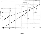
- FIG. 7 is a graph that illustrates the effective output sound pressure level (SPL) versus the input sound pressure level.
- SPL effective output sound pressure level
- the hearing systems 40 of the present invention provide an open auditory ear canal 17
- ambient sound is able to be directly transmitted through the auditory ear canal and directly onto the tympanic membrane 17.
- the line labeled “acoustic” shows the acoustic signal that directly reaches the tympanic membrane through the open ear canal.
- the line labeled “amplified” illustrates the signal that is directed to the tympanic membrane through the hearing system of the present invention. Below the input knee level Lk, the output increases linearly.
- the amplified output signal is limited and no longer increases with increasing input level. Between input levels Lk and Ls, the output maybe be compressed, as shown.
- the line labeled "Combined Acoustic + Amplified” illustrates the combined effect of both the acoustic signal and the amplified signal. Note that despite the fact that the output of the amplified system is saturated above Ls, the combined effect is that effective sound input continues to increase due to the acoustic input from the open canal.
Description
- 1. Field of the Invention. The present invention relates to hearing systems. More specifically, the present invention relates to hearing systems that have improved high frequency response that improves the speech reception threshold (SRT) and preserves and transmits high frequency spatial localization cues to the middle or inner ear. Such systems may be used to enhance the hearing process with normal or impaired hearing.
- Previous studies have shown that when the bandwidth of speech is low pass filtered, that speech intelligibility does not improve for bandwidths above about 3 kHz (Fletcher 1995), which is the reason why the telephone system was designed with a bandwidth limit to about 3.5 kHz, and also why hearing aid bandwidths are limited to frequencies below about 5.7 kHz (Killion 2004). It is now evident that there is significant energy in speech above about 5 kHz (Jin et al., J. Audio Eng. Soc., Munich 2002). Furthermore, hearing impaired subjects, with amplified speech, perform better with increased bandwidth in quiet (Vickers et al. 2001) and in noisy situations (Baer et al. 2002). This is especially true in subjects that do not have dead regions in the cochlea at the high frequencies (Moore, "Loudness perception and intensity resolution," Cochlear Hearing Loss, Chapter 4, pp. 90-115, Whurr Publishers Ltd., London 1998). Thus, subjects with hearing aids having greater bandwidth than the existing 5.7 kHz bandwidths can be expected to have improved performance in quiet and in diffuse-field noisy conditions.
- Numerous studies, both in humans (Shaw 1974) and in cats (Musicant et al. 1990) have shown that sound pressure at the ear canal entrance varies with the location of the sound source for frequencies above 5 kHz. This spatial filtering is due to the diffraction of the incoming sound wave by the pinna. It is well established that these diffraction cues help in the perception of spatial localization (Best et al., "The influence of high frequencies on speech localization," Abstract 981 (February 24, 2003) from <www.aro.org/abstracts/abstracts.html>). Due to the limited bandwidth of conventional hearing aids, some of the spatial localization cues are removed from the signal that is delivered to the middle and/or inner ear. Thus, it is oftentimes not possible for wearers of conventional hearing aids to accurately externalize talkers, which requires speech energy above 5 kHz.
- The eardrum to ear canal entrance pressure ratio has a 10dB resonance at about 3.5 kHz (Wiener et al. 1966; Shaw 1974). This is independent of the sound source location in the horizontal plane (Burkhard and Sachs 1975). This ratio is a function of the dimensions and consequent relative acoustic impedance of the eardrum and the ear canal. Thus, once the diffracted sound wave propagates past the entrance of the ear canal, there is no further spatial filtering. In other words, for spatial localization, there is no advantage to placing the microphone any more medial than near the entrance of the ear canal. The 10 dB resonance is typically added in most hearing aids after the microphone input because this gain is not spatially dependent.
- Evidence is now growing that the perception of the differences in the spatial locations of multiple talkers aid in the segregation of concurrent speech (Freyman et al. 1999; Freyman et al. 2001). Consistent with other studies, Carlile et al., "Spatialisation of talkers and the segregation of concurrent speech," Abstract 1264 (February 24, 2004) from <www.aro.org/abstracts/abstracts.html>, showed a speech reception threshold (SRT) of -4 dB under diotic conditions, where speech and masker noise at the two ears are the same, and -20 dB with speech maskers spatially separated by 30 degrees. But when the speech signal was low pass filtered to 5 kHz, the SRT decreased to -15 dB. While previous single channel studies have indicated that information in speech above 5 kHz does not contribute to speech intelligibility, these data indicate that as much as 5 dB unmasking afforded by externalization percept was much reduced when compared to the wide bandwidth presentation over virtual auditory simulations. The 5 dB improvement in SRT is mostly due to central mechanisms. However, at this point, it is not clear how much of the 5 dB improvement can be attained with auditory cues through a single channel (e.g., one ear).
- It has recently been described in P.M. Hofman et al., "Relearning sound localization with new ears," Nature Neuroscience, vol. 1, no. 5, Sept 1998, that sound localization relies on the neural processing of implicit acoustic cues. Hofman et al. found that accurate localization on the basis of spectral cues poses constraints on the sound spectrum, and that a sound needs to be broad-band in order to yield sufficient spectral shape information. However, with conventional hearing systems, because the ear canal is often completely blocked and because conventional hearing systems often have a low bandwidth filter, such conventional systems will not allow the user to receive the three-dimensional localization spatial cues.
- Furthermore, Wightman and Kistler (1997) found that listeners do not localize virtual sources of sound when sound is presented to only one ear. This suggests that high-frequency spectral cues presented to one ear through a hearing device may not be beneficial. Martin et al. (2004) recently showed that when the signal to one ear is low-pass filtered (2.5 kHz), thus preserving binaural information regarding sound-source lateral angle, monaural spectral cues to the opposite ear could correctly interpret elevation and front-back hemi-field cues. This says that a subject with one wide-band hearing aid can localize sounds with that hearing aid, provided that the opposite ear does not have significant low-frequency hearing loss, and thus able to process inter-aural time difference cues. The improvement in unmasking due to externalization observed by Carlile et al. (2004) should at least be possible with monaural amplification. The open question is how much of the 5 dB improvement in SRT can be realized monaurally and with a device that partially blocks the auditory ear canal.
- Head related transfer functions (HRTFs) are due to the diffraction of the incoming sound wave by the pinna. Another factor that determines the measured HRTF is the opening of the ear canal itself. It is conceivable that a device in the ear canal that partially blocks it and thus will alter HRTFs, can eliminate directionally dependent pinna cues. Burkhard and Sachs (1975) have shown that when the canal is blocked, spatially dependent vertical localization cues are modified but nevertheless present. Some relearning of the new cues maybe required to obtain benefit from the high frequency cues. Hoffman et al. (1998) showed that this learning takes place over a period of less than 45 days.
- Presently, most conventional hearing systems fall into at least three categories: acoustic hearing systems, electromagnetic drive hearing systems, and cochlear implants. Acoustic hearing systems rely on acoustic transducers that produce amplified sound waves which, in turn, impart vibrations to the tympanic membrane or eardrum. The telephone earpiece, radio, television and aids for the hearing impaired are all examples of systems that employ acoustic drive mechanisms. The telephone earpiece, for instance, converts signals transmitted on a wire into vibrational energy in a speaker which generates acoustic energy. This acoustic energy propagates in the ear canal and vibrates the tympanic membrane. These vibrations, at varying frequencies and amplitudes, result in the perception of sound. Surgically implanted cochlear implants electrically stimulate the auditory nerve ganglion cells or dendrites in subjects having profound hearing loss.
- Hearing systems that deliver audio information to the ear through electromagnetic transducers are well known. These transducers convert electromagnetic fields, modulated to contain audio information, into vibrations which are imparted to the tympanic membrane or parts of the middle ear. The transducer, typically a magnet, is subjected to displacement by electromagnetic fields to impart vibrational motion to the portion to which it is attached, thus producing sound perception by the wearer of such an electromagnetically driven system. This method of sound perception possesses some advantages over acoustic drive systems in terms of quality, efficiency, and most importantly, significant reduction of "feedback," a problem common to acoustic hearing systems.
- Feedback in acoustic hearing systems occurs when a portion of the acoustic output energy returns or "feeds back" to the input transducer (microphone), thus causing self-sustained oscillation. The potential for feedback is generally proportional to the amplification level of the system and, therefore, the output gain of many acoustic drive systems has to be reduced to less than a desirable level to prevent a feedback situation. This problem, which results in output gain inadequate to compensate for hearing losses in particularly severe cases, continues to be a major problem with acoustic type hearing aids. To minimize the feedback to the microphone, many acoustic hearing devices close off, or provide minimal venting, to the ear canal. Although feedback may be reduced, the tradeoff is "occlusion," a tunnel-like hearing sensation that is problematic to most hearing aid users. Directly driving the eardrum can minimize the feedback because the drive mechanism is mechanical rather than acoustic. Because of the mechanically vibrating eardrum, sound is coupled to the ear canal and wave propagation is supported in the reverse direction. The mechanical to acoustic coupling, however, is not efficient and this inefficiency is exploited in terms of decreased sound in the ear canal resulting in increased system gain.
- One system, which non-invasively couples a magnet to tympanic membrane and solves some of the aforementioned problems, is disclosed by
Perkins et al. in U.S. Patent No. 5,259,032 . The Perkins patent discloses a device for producing electromagnetic signals having a transducer assembly which is weakly but sufficiently affixed to the tympanic membrane of the wearer by surface adhesion.U.S. Patent No. 5,425,104 discloses a device for producing electromagnetic signals incorporating a drive means external to the acoustic canal of the individual. However, because magnetic fields decrease in strength as the reciprocal of the square of the distance (1/R2), previous methods for generating audio carrying magnetic fields are highly inefficient and are thus not practical. - While the conventional hearing aids have been relatively successful at improving hearing, the conventional hearing aids have not been able to significantly improve preservation of high-frequency spatial localization cues. For these reasons it would be desirable to provide an improved hearing systems.
- 2. Description of the Background Art.
U.S. Patent Nos. 5,259,032 and5,425,104 have been described above. Other patents of interest include:5,015,225 ;5,276,910 ;5,456,654 ;5,797,834 ;6,084,975 ;6,137,889 ;6,277,148 ;6,339,648 ;6,354,990 ;6,366,863 ;6,387,039 ;6,432,248 ;6,436,028 ;6,438,244 ;6,473,512 ;6,475,134 ;6,592,513 ;6,603,860 ;6,629,922 ;6,676,592 ; and6,695,943 . Other publications of interest include:U.S. Patent Publication Nos. 2002-0183587 ,2001-0027342 ; Journal publications Decraemer et al., "A method for determining three-dimensional vibration in the ear," Hearing Res., 77:19-37 (1994); Puria et al., "Sound-pressure measurements in the cochlear vestibule of human cadaver ears," J. Acoust. Soc. Am., 101(5):2754-2770 (May 1997); Moore, "Loudness perception and intensity resolution," Cochlear Hearing Loss, Chapter 4, pp. 90-115, Whurr Publishers Ltd., London (1998); Puria and Allen "Measurements and model of the cat middle ear: Evidence of tympanic membrane acoustic delay," J. Acoust. Soc. Am., 104(6):3463-3481 (December 1998); Hoffman et al. (1998); Fay et al., "Cat eardrum response mechanics," Calladine Festschrift (2002), Ed. S. Pellegrino, The Netherlands, Kluwer Academic Publishers; and Hato et al., "Three-dimensional stapes footplate motion in human temporal bones," Audiol. Neurootol., 8:140-152 (January 30, 2003). Conference presentation abstracts: Best et al., "The influence of high frequencies on speech localization," Abstract 981 (February 24, 2003) from <www.aro.org/abstracts/abstracts.html>, and Carlile et al., "Spatialisation of talkers and the segregation of concurrent speech," Abstract 1264 (February 24,2004) from <www.aro.org/abstracts/abstracts.html>. -
US 5,624,376 describes a floating mass transducer for improving hearing. The floating mass transducer may be implanted or mounted externally for producing vibrations in a vibratory structure of an ear. The floating mass transducer comprises a magnet assembly and a coil secured inside a housing which is fixed to an ossicle of the middle ear. The coil is more rigidly secured to the housing than the magnet and the magnet assembly and coil are configured such that alternating electrical current flowing through the coil results in vibration of the magnet assembly and coil relative to one another. Because the coil is more rigidly secured to the housing than the magnet assembly, the vibrations of the coil cause the housing to vibrate and these vibrations are conducted to the oval window of the ear via the ossicles. As another possibility the floating mass transducer may produce vibrations using piezoelectric materials. -
WO 01/50815 - The present invention is set out in the appended claims. Described herein are hearing system and methods that have an improved high frequency response that improves the speech reception threshold and preserves high frequency spatial localization cues to the middle or inner ear.
- generally comprise an input transducer assembly, a transmitter assembly, and an output transducer assembly. The input transducer assembly will receive a sound input, typically either ambient sound (in the case of hearing aids for hearing impaired individuals) or an electronic sound signal from a sound producing or receiving device, such as the telephone, a cellular telephone, a radio, a digital audio unit, or any one of a wide variety of other telecommunication and/or entertainment devices. The input transducer assembly will send a signal to the transmitter assembly where the transmitter assembly processes the signal from the transducer assembly to produce a processed signal which is modulated in some way, to represent or encode a sound signal which substantially represents the sound input received by the input transducer assembly. The exact nature of the processed output signal will be selected to be used by the output transducer assembly to provide both the power and the signal so that the output transducer assembly can produce mechanical vibrations, acoustical output, pressure output, (or other output) which, when properly coupled to a subject's hearing transduction pathway, will induce neural impulses in the subject which will be interpreted by the subject as the original sound input, or at least something reasonably representative of the original sound input.
- At least some of the components of a described hearing system are disposed within a shell or housing that is placed within the subject's auditory ear canal. Typically, the shell has one or more openings on both a first end and a second end so as to provide an open ear canal and to allow ambient sound (such as low and high frequency three dimensional localization cues) to be directly delivered to the tympanic membrane at a high level. Advantageously, the openings in the shell do not block the auditory canal and minimize interference with the normal pressurization of the ear. In some embodiments, the shell houses the input transducer, the transmitter assembly, and a battery. In other embodiments, portions of the transmitter assembly and the battery may be placed behind the ear (BTE), while the input transducer is positioned in the shell.
- In the case of hearing aids, the input transducer assembly typically comprises a microphone in the housing that is disposed within the auditory ear canal. Suitable microphones are well known in the hearing aid industry and amply described in the patent and technical literature. The microphones will typically produce an electrical output is received by the transmitter assembly which in turn will produce the processed signal. In the case of ear pieces and other hearing systems, the sound input to the input transducer assembly will typically be electronic, such as from a telephone, cell phone, a portable entertainment unit, or the like. In such cases, the input transducer assembly will typically have a suitable amplifier or other electronic interface which receives the electronic sound input and which produces a filtered electronic output suitable for driving the output transducer assembly.
- While it is possible to position the microphone behind the pinna, in the temple piece of eyeglasses, or elsewhere on the subject, it is preferable to position the microphone within the ear canal so that the microphone receives and transmits the higher frequency signals that are directed into the ear canal and to thus improve the final SRT.
- The transmitter assembly typically comprises a digital signal processor that processes the electrical signal from the input transducer and delivers a signal to a transmitter element that produces the processed output signal that actuates the output transducer. The digital signal processor will often have a filter that has a frequency response bandwidth that is typically greater than 6 kHz, more preferably between about 6 kHz and about 20 kHz, and most preferably between about 7 kHz and 13 kHz. Such a transmitter assembly differs from conventional transmitters found in that the higher bandwidth results in greater preservation of spatial localization cues for microphones that are placed at the entrance of the ear canal or within the ear canal.
- In one described example, the transmitter element that is in communication with the digital signal processor is in the form of a coil that has an open interior and a core sized to fit within the open interior of the coil. A power source is coupled to the coil to supply a current to the coil. The current delivered to the coil will substantially correspond to the electrical signal processed by the digital signal processor. One useful electromagnetic-based assembly is described in commonly owned, copending
U.S. Patent Application Serial No. 10/902,660, filed July 28, 2004 - The output transducer assembly may be any component that is able to receive the processed signal from the transmitter assembly. The output transducer assembly will typically be configured to couple to some point in the hearing transduction pathway of the subject in order to induce neural impulses which are interpreted as sound by the subject. Typically, a portion of the output transducer assembly will couple to the tympanic membrane, a bone in the ossicular chain, or directly to the cochlea where it is positioned to vibrate fluid within the cochlea. Specific points of attachment are described in prior
U.S. Patent Nos. 5,259,032 ;5,456,654 ;6,084,975 ; and6,629,922 . - In one described example, there is provided a hearing system that has an input transducer that is positionable within an ear canal of a user to capture ambient sound that enters the ear canal of the user. A transmitter assembly receives electrical signals from the input transducer. The transmitter assembly comprises a signal processor that has a frequency response bandwidth in a 6.0 kHz to 20 kHz range. The transmitter assembly is configured to deliver filtered signals to an output transducer positioned in a middle or inner ear of the user, wherein the filtered signal is representative of the ambient sound received by the input transducer. A configuration of the input transducer and transmitter assembly provides an open ear canal that allows ambient sound to directly reach the middle ear of the user.
- A described method comprises positioning an input transducer within an ear canal of a user and transmitting signals from the input transducer that are indicative of ambient sound received by the input transducer to a transmitter assembly. The signals are processed (e.g., filtered) at the transmitter assembly with a signal processor that has a filter that has a bandwidth that is larger than about 6.0 kHz. The filtered signals are delivered to a middle ear or inner ear of the user. The positioning of the input transducer and transmitter assembly provides an open ear canal that allows non-filtered ambient sound to directly reach the middle ear of the user.
- As noted above, in preferred examples, the signal processor has a bandwidth between about 6 kHz and about 20 kHz, so as to allow for preservation and transmission of the high frequency spatial localization cues.
- While the remaining discussion will focus on the use of an electromagnetic transmitter assembly and output transducer, it should be appreciated that the present invention is not limited to such transmitter assemblies, and various other types of transmitter assemblies may be used. For example, the photo-mechanical hearing transduction assembly described in co-pending and commonly owned,
U.S. Provisional Patent Application Serial No. 60/618,408, filed October 12, 2004 - The above aspects and other aspects of the present invention may be more fully understood from the following detailed description, taken together with the accompanying drawings.
-
-
FIG. 1 is a cross-sectional view of a human ear, including an outer ear, middle ear, and part of an inner ear. -
FIG. 2 illustrates one example of the present invention with a transducer coupled to a tympanic membrane. -
FIGS. 3A and 3B illustrate alternative examples of a transducer coupled to a malleus. -
FIG. 4A schematically illustrates a hearing system that provides an open ear canal so as to allow ambient sound/acoustic signals to directly reach the tympanic membrane. -
FIG. 4B illustrates an alternative example of a hearing system with the coil laid along an inner wall of the shell. -
FIG. 5 schematically illustrates a hearing system. -
FIG. 6A illustrates a hearing system having a microphone (input transducer) positioned on an inner surface of a canal shell and a transmitter assembly positioned in an ear canal that is in communication with the transducer that is coupled to the tympanic membrane. -
FIG. 6B illustrates an alternative medial view with a microphone in the canal shell wall near the entrance. -
FIG. 7 is a graph that illustrates an acoustic signal that reaches the ear drum and the effective amplified signal at the eardrum and the combined effect of the two. - Referring now to
FIG. 1 , there is shown a cross sectional view of anouter ear 10,middle ear 12 and a portion of aninner ear 14. Theouter ear 10 comprises primarily of thepinna 15 and theauditory ear canal 17. Themiddle ear 12 is bounded by the tympanic membrane (ear drum) 16 on one side, and contains a series of three tiny interconnnected bones: the malleus (hammer) 18; the incus (anvil) 20; and the stapes (stirrup) 22. Collectively, these three bones are known as the ossicles or the ossicular chain. Themalleus 18 is attached to thetympanic membrane 16 while thestapes 22, the last bone in the ossicular chain, is coupled to thecochlea 24 of the inner ear. - In normal hearing, sound waves that travel via the outer ear or
auditory ear canal 17 strike thetympanic membrane 16 and cause it to vibrate. Themalleus 18, being connected to thetympanic membrane 16, is thus also set into motion, along with theincus 20 and the stapes 22. These three bones in the ossicular chain act as a set of impedance matching levers of the tiny mechanical vibrations received by the tympanic membrane. Thetympanic membrane 16 and the bones may act as a transmission line system to maximize the bandwidth of the hearing apparatus (Puria and Allen, 1998). The stapes vibrates in turn causing fluid pressure in the vestibule of a spiral structure known as the cochlea 24 (Puria et al. 1997). The fluid pressure results in a traveling wave along the longitudinal axis of the basilar membrane (not shown). The organ of Corti sits atop the basilar membrane which contains the sensory epithelium consisting of one row of inner hair cells and three rows of outer hair cells. The inner-hair cells (not shown) in the cochlea are stimulated by the movement of the basilar membrane. There, hydraulic pressure displaces the inner ear fluid and mechanical energy in the hair cells is transformed into electrical impulses, which are transmitted to neural pathways and the hearing center of the brain (temporal lobe), resulting in the perception of sound. The outer hair cells are believed to amplify and compress the input to the inner hair cells. When there is sensory-neural hearing loss, the outer hair cells are typically damaged, thus reducing the input to the inner hair cells which results in a reduction in the perception of sound. Amplification by a hearing system may fully or partially restore the otherwise normal amplification and compression provided by the outer hair cells. - A presently preferred coupling point of the output transducer assembly is on the outer surface of the
tympanic membrane 16 and is illustrated inFIG. 2 . InFIG. 2 , theoutput transducer assembly 26 comprises atransducer 28 that is placed in contact with an exterior surface of thetympanic membrane 10. Thetransducer 28 generally comprises a high-energy permanent magnet. A preferred method of positioning the transducer is to employ a contact transducer assembly that includestransducer 28 and asupport assembly 30.Support assembly 30 is attached to, or floating on, a portion of thetympanic membrane 16. The support assembly is a biocompatible structure with a surface area sufficient to support thetransducer 28, and is vibrationally coupled to thetympanic membrane 16. - Preferably, the surface of
support assembly 30 that is attached to the tympanic membrane substantially conforms to the shape of the corresponding surface of the tympanic membrane, particularly theumbo area 32. In one embodiment, thesupport assembly 30 is a conically shaped film in which the transducer is embedded therein. In such embodiments, the film is releasably contacted with a surface of the tympanic membrane. Alternatively, a surface wetting agent, such as mineral oil, is preferably used to enhance the ability ofsupport assembly 30 to form a weak but sufficient attachment to thetympanic membrane 16 through surface adhesion. One suitable contact transducer assembly is described inU.S. Pat. No. 5,259,032 . -
FIGS. 3A and 3B illustrate alternative embodiments wherein a transducer is placed on the malleus of an individual. InFIG. 3A , atransducer magnet 34 is attached to the medial side of the inferior manubrium. Preferably,magnet 34 is encased in titanium or other biocompatible material. By way of illustration, one method of attachingmagnet 34 to the malleus is disclosed inU.S. Patent No. 6,084,975 ,
whereinmagnet 34 is attached to the medial surface of themanubrium 44 of themalleus 18 by making an incision in the posterior periosteum of the lower manubrium, and elevating the periosteum from the manubrium, thus creating a pocket between the lateral surface of the manubrium and thetympanic membrane 10. One prong of a stainless steel clip device may be placed into the pocket, with thetransducer magnet 34 attached thereto. The interior of the clip is of appropriate dimension such that the clip now holds onto the manubrium placing the magnet on its medial surface. - Alternatively,
FIG. 3B illustrates an embodiment whereinclip 36 is secured around the neck of themalleus 18, in between the manubrium and thehead 38 of the malleus. In this embodiment, theclip 36 extends to provide a platform of orienting thetransducer magnet 34 toward thetympanic membrane 16 andear canal 17 such that thetransducer magnet 34 is in a substantially optimal position to receive signals from the transmitter assembly. -
FIG. 4A illustrates one preferred embodiment of ahearing system 40.
Thehearing system 40 comprises the transmitter assembly 42 (illustrated withshell 44 cross-sectioned for clarity) that is installed in a right ear canal and oriented with respect to themagnetic transducer 28 on thetympanic membrane 16. In the preferred embodiment, thetransducer 28 is positioned againsttympanic membrane 16 atumbo area 32. The transducer may also be placed on other acoustic members of the middle ear, including locations on the malleus 18 (shown inFIGS. 3A and 3B ),incus 20, andstapes 22. When placed in theumbo area 32 of thetympanic membrane 16, thetransducer 28 will be naturally tilted with respect to theear canal 17. The degree of tilt will vary from individual to individual, but is typically at about a 60-degree angle with respect to the ear canal. - The
transmitter assembly 42 has ashell 44 configured to mate with the characteristics of the individual's ear canal wall.Shell 44 is preferably matched to fit snug in the individual's ear canal so that thetransmitter assembly 42 may repeatedly be inserted or removed from the ear canal and still be properly aligned when re-inserted in the individual's ear. In the illustrated embodiment,shell 44 is also configured to support acoil 46 and a core 48 such that the tip ofcore 48 is positioned at a proper distance and orientation in relation to thetransducer 28 when thetransmitter assembly 42 is properly installed in theear canal 17. The core 48 generally comprises ferrite, but may be any material with high magnetic permeability. - In a preferred embodiment,
coil 46 is wrapped around the circumference of thecore 48 along part or all of the length of the core. Generally, the coil has a sufficient number of rotations to optimally drive an electromagnetic field toward thetransducer 28. The number of rotations may vary depending on the diameter of the coil, the diameter of the core, the length of the core, and the overall acceptable diameter of the coil and core assembly based on the size of the individual's ear canal. Generally, the force applied by the magnetic field on the magnet will increase, and therefore increase the efficiency of the system, with an increase in the diameter of the core. These parameters will be constrained, however, by the anatomical limitations of the individual's ear. Thecoil 46 may be wrapped around only a portion of the length of the core, as shown inFIG. 4A , allowing the tip of the core to extend further into theear canal 17, which generally converges as it reaches thetympanic membrane 16. - One method for matching the
shell 44 to the internal dimensions of the ear canal is to make an impression of the ear canal cavity, including the tympanic membrane. A positive investment is then made from the negative impression. The outer surface of the shell is then formed from the positive investment which replicated the external surface of the impression. Thecoil 46 andcore 48 assembly can then be positioned and mounted in theshell 44 according to the desired orientation with respect to the projected placement of thetransducer 28, which may be determined from the positive investment of the ear canal and tympanic membrane. In an alternative embodiment, thetransmitter assembly 42 may also incorporate a mounting platform (not shown) with micro-adjustment capability for orienting the coil and core assembly such that the core can be oriented and positioned with respect to the shell and/or the coil. In another alternative embodiment, a CT, MRI or optical scan may be performed on the individual to generate a 3D model of the ear canal and the tympanic membrane. The digital 3D model representation may then be used to form the outside surface of theshell 44 and mount the core and coil. - As shown in the embodiment of
FIG. 4A ,transmitter assembly 42 may also comprise a digital signal processing (DSP) unit andother components 50 and abattery 52 that are placed insideshell 44. Theproximal end 53 of theshell 44 is open 54 and has the input transducer (microphone) 56 positioned on the shell so as to directly receive the ambient sound that enters theauditory ear canal 17. Theopen chamber 58 provides access to theshell 44 andtransmitter assembly 42 components contained therein. Apull line 60 may also be incorporated into theshell 44 so that the transmitter assembly can be readily removed from the ear canal. - An
acoustic opening 62 of the shell allows
ambient sound to enter theopen chamber 58 of the shell. This allows ambient sound to travel through theopen volume 58 along the internal compartment of thetransmitter assembly 42 and through one ormore openings 64 at the distal end of theshell 44. Thus, ambient sound waves may reach and directly vibrate thetympanic membrane 16 and separately impart vibration on the tympanic membrane. This open-channel design provides a number of substantial benefits. First, theopen channel 17 minimizes the occlusive effect prevalent in many acoustic hearing systems from blocking the ear canal. Second, the open channel allows the high frequency spatial localization cues to be directly transmitted to thetympanic membrane 17. Third, the natural ambient sound entering theear canal 16 allows the electromagnetically driven effective sound level output to be limited or cut off at a much lower level than with a hearing system that blocks theear canal 17. Finally, having a fully open shell preserves the natural pinna diffraction cues of the subject and thus little to no acclimatization, as described by Hoffinan et al. (1998), is required. - As shown schematically in
FIG. 5 , in operation, ambient sound entering the auricle andear canal 17 is captured by themicrophone 56 that is positioned within theopen ear canal 17. Themicrophone 56 converts sound waves into analog electrical signals for processing by aDSP unit 68 of thetransmitter assembly 42. TheDSP unit 68 may optionally be coupled to an input amplifier (not shown) to amplify the electrical signal. TheDSP unit 68 typically includes an analog-to-digital converter 66 that converts the analog electrical signal to a digital signal. The digital signal is then processed by any number of digital signal processors and filters 68. The processing may comprise of any combination of frequency filters, multi-band compression, noise suppression and noise reduction algorithms. The digitally processed signal is then converted back to analog signal with a digital-to-analog converter 70. The analog signal is shaped and amplified and sent to thecoil 46, which generates a modulated electromagnetic field containing audio information representative of the original audio signal and, along with thecore 48, directs the electromagnetic field toward thetransducer magnet 28. Thetransducer magnet 28 vibrates in response to the electromagnetic field, thereby vibrating the middle-ear acoustic member to which it is coupled (e.g. thetympanic membrane 16 inFIG. 4A or themalleus 18 inFIGS. 3A and 3B ). - In one preferred embodiment, the
transmitter assembly 42 comprises a filter that has a frequency response bandwidth that is typically greater than 6 kHz, more preferably between about 6 kHz and about 20 kHz, and most preferably between about 6 kHz and 13 kHz. Such atransmitter assembly 42 differs from conventional transmitters found in conventional hearing aids in that the higher bandwidth results in greater preservation of spatial localization cues formicrophones 56 that are placed at the entrance of the auditory ear canal or within theear canal 17. The positioning of themicrophone 56 and the higher bandwidth filter results in a speech reception threshold improvement of up to 5 dB above existing hearing systems where there are interfering speech sources. Such a significant improvement in SRT, due to central mechanisms, is not possible with existing hearing aids with limited bandwidth, limited gain and sound processing without pinna diffraction cues. - For most hearing-impaired subjects, sound reproduction at higher decibel ranges is not necessary because their natural hearing mechanisms are still capable of receiving sound in that range. To those familiar in the art, this is commonly referred to as the recruitment phenomena where the loudness perception of a hearing impaired subject "catches up" with the loudness perception of a normal hearing person at loud sounds (Moore, 1998). Thus, the open-channel device may be configured to switch off, or saturate, at levels where natural acoustic hearing takes over. This can greatly reduce the currents required to drive the transmitter assembly, allowing for smaller batteries and/or longer battery life. A large opening is not possible in acoustic hearing aids because of the increase in feedback and thus limiting the functional gain of the device. In the electromagnetically driven devices of the present invention, acoustic feedback is significantly reduced because the tympanic membrane is directly vibrated. This direct vibration ultimately results in generation of sound in the ear canal because the tympanic membrane acts as a loudspeaker cone. However, the level of generated acoustic energy is significantly less than in conventional hearing aids that generate direct acoustic energy in the ear canal. This results in much greater functional gain for the open ear canal electromagnetic transmitter and transducer than with conventional acoustic hearing aids.
- Because the input transducer (e.g., microphone) is positioned in the ear canal, the microphone is able to receive and retransmit the high-frequency three dimensional spatial cues. If the microphone was not positioned within the auditory ear canal, (for example, if the microphone is placed behind-the ear (BTE)), then the signal reaching its microphone does not carry the spatially dependent pinna cues. Thus there is little chance for there to be spatial information.
-
FIG. 4B illustrates an alternative embodiment of atransmitter assembly 42 wherein themicrophone 56 is positioned near the opening of the ear canal onshell 44 and thecoil 46 is laid on the inner walls of theshell 44. Thecore 62 is positioned within the inner diameter of thecoil 46 and may be attached to either theshell 44 or thecoil 46. In this embodiment, ambient sound may still enter ear canal and pass through theopen chamber 58 and out theports 68 to directly vibrate thetympanic membrane 16. - Now referring to
FIGS. 6A and 6B , an alternative embodiment is illustrated wherein one or more of theDSP unit 50 andbattery 52 are located external to the auditory ear canal in adriver unit 70.Driver unit 70 may hook on to the top end of thepinna 15 viaear hook 72. This configuration provides additional clearance for theopen chamber 58 of shell 44 (FIG. 4B ), and also allows for inclusion of components that would not otherwise fit in the ear canal of the individual. In such embodiments, it is still preferable to have themicrophone 56 located in or at the opening of theear canal 17 to gain benefit of high bandwidth spatial localization cues from theauricle 17. As shown inFIGS. 6A and 6B , sound entering theear canal 17 is captured bymicrophone 56. The signal is then sent to theDSP unit 50 located in thedriver unit 70 for processing via an input wire incable 74 connected to jack 76 inshell 44. Once the signal is processed by theDSP unit 50, the signal is delivered to thecoil 46 by an output wire passing back throughcable 74. -
FIG. 7 is a graph that illustrates the effective output sound pressure level (SPL) versus the input sound pressure level. As shown in the graph, since thehearing systems 40 of the present invention provide an openauditory ear canal 17, ambient sound is able to be directly transmitted through the auditory ear canal and directly onto thetympanic membrane 17. As shown in the graph, the line labeled "acoustic" shows the acoustic signal that directly reaches the tympanic membrane through the open ear canal. The line labeled "amplified" illustrates the signal that is directed to the tympanic membrane through the hearing system of the present invention. Below the input knee level Lk, the output increases linearly. Above input saturation level Ls, the amplified output signal is limited and no longer increases with increasing input level. Between input levels Lk and Ls, the output maybe be compressed, as shown. The line labeled "Combined Acoustic + Amplified" illustrates the combined effect of both the acoustic signal and the amplified signal. Note that despite the fact that the output of the amplified system is saturated above Ls, the combined effect is that effective sound input continues to increase due to the acoustic input from the open canal. - The foregoing description of a preferred embodiment of the invention has been presented for purposes of illustration and description. It is not intended to be exhaustive or to limit the invention to the precise forms disclosed. Obviously, many modifications and variations will be apparent to practitioners skilled in this art. It is intended that the scope of the invention be defined by the following claims.
Claims (15)
- A hearing system comprising:an input transducer (56) configured to capture ambient sound, including high frequency localization cues, and convert captured ambient sound into electrical signals; anda transmitter assembly (42) configured to receive the electrical signals from the input transducer (56), the transmitter assembly comprising a signal processor configured to generate filtered signals from the received electrical signals, the transmitter assembly comprising a transmitter, the transmitter assembly configured to deliver both power and filtered signals from the transmitter to produce mechanical vibrations with an output transducer (26) configured to couple to a position on a tympanic membrane, in a middle ear, or inner ear of a user, the filtered signals being representative of the ambient sound received by the input transducer,wherein the transmitter assembly (42) is positionable within the ear canal to provide an open canal to allow the ambient sound to pass through the open canal and bypass the transmitter assembly to directly reach the middle ear of the user, wherein the signal processor is configured to amplify the filtered signals that comprise the high frequency localization cues below a saturation level and to switch off, or saturate, at levels where natural acoustic hearing takes over and provide greater equivalent sound pressure to the eardrum with the ambient sound than equivalent sound pressure of the output transducer.
- The hearing system of claim 1, comprising a housing (44) having an outer surface configured to match to an ear canal of the user, the housing having an open chamber (58) comprising a first end having an acoustic opening (62) to allow ambient sound into the open chamber (58), and a second end having one or more openings (64) to allow ambient sound to reach directly the tympanic membrane of the user.
- The hearing system of claim 1 or 2, wherein the transmitter assembly (42) comprises a transmission element, the transmitter assembly configured to deliver the filtered signals from the transmitter through a tip of the transmission element (48) to the output transducer (26), preferably wherein the transmitter assembly is configured such that the tip of the transmission element (48) is supported within the housing to position the tip at a distance and orientation relative to the transducer.
- The hearing system of any of claims 1 to 3, wherein the transmitter assembly comprises an acoustic transmitter, ultrasound transmitter, infrared transmitter, an optical transmitter, or a fluid pressure transmitter.
- The hearing system of any of claims 1 to 3, wherein the transmitter assembly comprises an electromagnetic transmitter and wherein the transmission element comprises an electromagnetic transmission element that receives a signal from the signal processor, the electromagnetic transmitter being arranged to deliver the filtered signals to the output transducer through the electromagnetic transmission element.
- The hearing system of claim 5, wherein the output transducer is arranged to be coupled to an acoustic member of the middle ear and being configured to receive the filtered signals from the transmission element.
- The hearing system of any preceding claims, wherein the output transducer comprises a permanent magnet.
- The hearing system of any preceding claims, wherein the signal processor has a frequency response bandwidth in a 6 kHz to 20 kHz range.
- The hearing system of any preceding claims, wherein the output transducer is configured to couple to the tympanic membrane.
- The hearing system of any preceding claims, wherein the input transducer comprises a microphone to capture the ambient sound.
- The hearing system of any preceding claims, wherein the input transducer is configured to be positioned in the area of a pinna of the user, at an entrance of the ear canal of the user, within the ear canal of the user, or in a temple piece of eyeglasses.
- The hearing system of any preceding claims, wherein the output transducer is embedded in a conically shaped film that is configured to releasably contact a surface of the tympanic membrane.
- The hearing system of any preceding claims, wherein the input transducer is configured to receive an input sound signal from a sound producing or receiving device comprising a telephone, a cellular telephone, a radio, a digital audio unit, a portable entertainment unit, or other telecommunication and/or entertainment devices.
- A method comprising:receiving electrical signals with a transmitter assembly positioned to provide an open ear canal, wherein the electrical signals are indicative of the sound captured by an input transducer, the sound including high frequency localization cues;filtering the signals at the transmitter assembly with a signal processor; anddelivering both power and the filtered signals through a tip of a transmission element of the transmitter assembly to produce mechanical vibrations with an output transducer positioned on a tympanic membrane, in the middle ear or the inner ear of the user; andamplifying the filtered signals that comprise the high frequency localization cues below the saturation level and switching off, or saturating, at levels where natural acoustic hearing takes over, with the signal processor.
- The method of claim 14, wherein delivering filtered signals comprises delivering filtered optical signals.
Applications Claiming Priority (2)
| Application Number | Priority Date | Filing Date | Title |
|---|---|---|---|
| US11/121,517 US7668325B2 (en) | 2005-05-03 | 2005-05-03 | Hearing system having an open chamber for housing components and reducing the occlusion effect |
| EP06758467.2A EP1880574B1 (en) | 2005-05-03 | 2006-04-21 | Hearing system having improved high frequency response |
Related Parent Applications (1)
| Application Number | Title | Priority Date | Filing Date |
|---|---|---|---|
| EP06758467.2A Division EP1880574B1 (en) | 2005-05-03 | 2006-04-21 | Hearing system having improved high frequency response |
Publications (2)
| Publication Number | Publication Date |
|---|---|
| EP2802160A1 EP2802160A1 (en) | 2014-11-12 |
| EP2802160B1 true EP2802160B1 (en) | 2016-12-21 |
Family
ID=37308466
Family Applications (2)
| Application Number | Title | Priority Date | Filing Date |
|---|---|---|---|
| EP06758467.2A Active EP1880574B1 (en) | 2005-05-03 | 2006-04-21 | Hearing system having improved high frequency response |
| EP14179881.9A Active EP2802160B1 (en) | 2005-05-03 | 2006-04-21 | Hearing system having improved high frequency response |
Family Applications Before (1)
| Application Number | Title | Priority Date | Filing Date |
|---|---|---|---|
| EP06758467.2A Active EP1880574B1 (en) | 2005-05-03 | 2006-04-21 | Hearing system having improved high frequency response |
Country Status (6)
| Country | Link |
|---|---|
| US (6) | US7668325B2 (en) |
| EP (2) | EP1880574B1 (en) |
| JP (1) | JP5341507B2 (en) |
| CN (1) | CN101208992B (en) |
| DK (2) | DK1880574T3 (en) |
| WO (1) | WO2006118819A2 (en) |
Families Citing this family (51)
| Publication number | Priority date | Publication date | Assignee | Title |
|---|---|---|---|---|
| US7668325B2 (en) | 2005-05-03 | 2010-02-23 | Earlens Corporation | Hearing system having an open chamber for housing components and reducing the occlusion effect |
| US8295523B2 (en) * | 2007-10-04 | 2012-10-23 | SoundBeam LLC | Energy delivery and microphone placement methods for improved comfort in an open canal hearing aid |
| US7867160B2 (en) | 2004-10-12 | 2011-01-11 | Earlens Corporation | Systems and methods for photo-mechanical hearing transduction |
| US8401212B2 (en) | 2007-10-12 | 2013-03-19 | Earlens Corporation | Multifunction system and method for integrated hearing and communication with noise cancellation and feedback management |
| ATE410041T1 (en) * | 2005-05-13 | 2008-10-15 | Cesar Guilherme Vohringer | CIC HEARING AID |
| WO2007133814A2 (en) * | 2006-01-04 | 2007-11-22 | Moses Ron L | Implantable hearing aid |
| EP1992196B1 (en) * | 2006-03-03 | 2014-05-14 | Widex A/S | Hearing aid and method of compensation for direct sound in hearing aids |
| US8422709B2 (en) | 2006-03-03 | 2013-04-16 | Widex A/S | Method and system of noise reduction in a hearing aid |
| KR100859979B1 (en) * | 2007-07-20 | 2008-09-25 | 경북대학교 산학협력단 | Implantable middle ear hearing device with tube type vibration transducer |
| KR100931209B1 (en) * | 2007-11-20 | 2009-12-10 | 경북대학교 산학협력단 | Easy-to-install garden-driven vibration transducer and implantable hearing aid using it |
| KR20090076484A (en) * | 2008-01-09 | 2009-07-13 | 경북대학교 산학협력단 | Trans-tympanic membrane vibration member and implantable hearing aids using the member |
| JP4469898B2 (en) * | 2008-02-15 | 2010-06-02 | 株式会社東芝 | Ear canal resonance correction device |
| US20090299215A1 (en) * | 2008-05-30 | 2009-12-03 | Starkey Laboratories, Inc. | Measurement of sound pressure level and phase at eardrum by sensing eardrum vibration |
| US8396239B2 (en) * | 2008-06-17 | 2013-03-12 | Earlens Corporation | Optical electro-mechanical hearing devices with combined power and signal architectures |
| DK2301261T3 (en) | 2008-06-17 | 2019-04-23 | Earlens Corp | Optical electromechanical hearing aids with separate power supply and signal components |
| EP2301262B1 (en) | 2008-06-17 | 2017-09-27 | Earlens Corporation | Optical electro-mechanical hearing devices with combined power and signal architectures |
| US8737664B2 (en) * | 2008-06-18 | 2014-05-27 | Apple Inc. | In-the-ear porting structures for earbud |
| BRPI0918994A2 (en) * | 2008-09-22 | 2017-06-13 | SoundBeam LLC | device, and method for transmitting an audio signal to a user. |
| DK2237573T3 (en) * | 2009-04-02 | 2021-05-03 | Oticon As | Adaptive feedback suppression method and device therefor |
| EP2262285B1 (en) * | 2009-06-02 | 2016-11-30 | Oticon A/S | A listening device providing enhanced localization cues, its use and a method |
| EP2438768B1 (en) | 2009-06-05 | 2016-03-16 | Earlens Corporation | Optically coupled acoustic middle ear implant device |
| US9544700B2 (en) | 2009-06-15 | 2017-01-10 | Earlens Corporation | Optically coupled active ossicular replacement prosthesis |
| EP2443773B1 (en) * | 2009-06-18 | 2017-01-11 | Earlens Corporation | Optically coupled cochlear implant systems |
| WO2010148345A2 (en) | 2009-06-18 | 2010-12-23 | SoundBeam LLC | Eardrum implantable devices for hearing systems and methods |
| WO2011005479A2 (en) | 2009-06-22 | 2011-01-13 | SoundBeam LLC | Optically coupled bone conduction systems and methods |
| CN102598714A (en) | 2009-06-22 | 2012-07-18 | 音束有限责任公司 | Round window coupled hearing systems and methods |
| US8715154B2 (en) * | 2009-06-24 | 2014-05-06 | Earlens Corporation | Optically coupled cochlear actuator systems and methods |
| US8845705B2 (en) | 2009-06-24 | 2014-09-30 | Earlens Corporation | Optical cochlear stimulation devices and methods |
| WO2012082721A2 (en) * | 2010-12-13 | 2012-06-21 | The Board Of Trustees Of The University Of Illinois | Method and apparatus for evaluating dynamic middle ear muscle activity |
| WO2012088187A2 (en) | 2010-12-20 | 2012-06-28 | SoundBeam LLC | Anatomically customized ear canal hearing apparatus |
| WO2013016589A1 (en) * | 2011-07-26 | 2013-01-31 | Neukermans Armand P | Hearing aid for non-contact eardrum pressure activation |
| WO2013027373A1 (en) * | 2011-08-25 | 2013-02-28 | パナソニック株式会社 | Optical microphone |
| US9462365B1 (en) | 2012-03-14 | 2016-10-04 | Google Inc. | Structure and manufacture of bone-conduction transducer |
| US10034103B2 (en) | 2014-03-18 | 2018-07-24 | Earlens Corporation | High fidelity and reduced feedback contact hearing apparatus and methods |
| EP3169396B1 (en) | 2014-07-14 | 2021-04-21 | Earlens Corporation | Sliding bias and peak limiting for optical hearing devices |
| US9924276B2 (en) | 2014-11-26 | 2018-03-20 | Earlens Corporation | Adjustable venting for hearing instruments |
| US9794694B2 (en) * | 2015-03-11 | 2017-10-17 | Turtle Beach Corporation | Parametric in-ear impedance matching device |
| WO2017059240A1 (en) * | 2015-10-02 | 2017-04-06 | Earlens Corporation | Drug delivery customized ear canal apparatus |
| US10306381B2 (en) | 2015-12-30 | 2019-05-28 | Earlens Corporation | Charging protocol for rechargable hearing systems |
| US11350226B2 (en) | 2015-12-30 | 2022-05-31 | Earlens Corporation | Charging protocol for rechargeable hearing systems |
| US10492010B2 (en) | 2015-12-30 | 2019-11-26 | Earlens Corporations | Damping in contact hearing systems |
| CN112738700A (en) | 2016-09-09 | 2021-04-30 | 伊尔兰斯公司 | Smart mirror system and method |
| WO2018085271A1 (en) | 2016-11-01 | 2018-05-11 | Polyvagal Science LLC | Methods and systems for reducing sound sensitivities and improving auditory processing, behavioral state regulation and social engagement |
| WO2018093733A1 (en) | 2016-11-15 | 2018-05-24 | Earlens Corporation | Improved impression procedure |
| US10646331B2 (en) * | 2017-04-26 | 2020-05-12 | University Of Maryland, Baltimore | Ossicular prosthesis and method and system for manufacturing same |
| EP3682652A4 (en) * | 2017-09-13 | 2021-06-16 | Earlens Corporation | Contact hearing protection device |
| WO2019169220A1 (en) | 2018-03-01 | 2019-09-06 | Polyvagal Science LLC | Systems and methods for modulating physiological state |
| WO2019173470A1 (en) | 2018-03-07 | 2019-09-12 | Earlens Corporation | Contact hearing device and retention structure materials |
| WO2019199680A1 (en) | 2018-04-09 | 2019-10-17 | Earlens Corporation | Dynamic filter |
| EP3830961A4 (en) | 2018-07-31 | 2022-06-08 | Earlens Corporation | Modulation in a contact hearing system |
| EP3857915A4 (en) * | 2018-09-24 | 2022-06-22 | Med-El Elektromedizinische Geraete GmbH | Universal bone conduction and middle ear implant |
Citations (1)
| Publication number | Priority date | Publication date | Assignee | Title |
|---|---|---|---|---|
| WO2006014915A2 (en) * | 2004-07-28 | 2006-02-09 | Earlens Corporation | Improved transmitter and transducer for electromagnetic hearing devices |
Family Cites Families (408)
| Publication number | Priority date | Publication date | Assignee | Title |
|---|---|---|---|---|
| US3209082A (en) | 1957-05-27 | 1965-09-28 | Beltone Electronics Corp | Hearing aid |
| US3229049A (en) * | 1960-08-04 | 1966-01-11 | Goldberg Hyman | Hearing aid |
| US3440314A (en) | 1966-09-30 | 1969-04-22 | Dow Corning | Method of making custom-fitted earplugs for hearing aids |
| US3549818A (en) | 1967-08-15 | 1970-12-22 | Message Systems Inc | Transmitting antenna for audio induction communication system |
| US3585416A (en) | 1969-10-07 | 1971-06-15 | Howard G Mellen | Photopiezoelectric transducer |
| US3594514A (en) | 1970-01-02 | 1971-07-20 | Medtronic Inc | Hearing aid with piezoelectric ceramic element |
| US3710399A (en) | 1970-06-23 | 1973-01-16 | H Hurst | Ossicle replacement prosthesis |
| DE2044870C3 (en) | 1970-09-10 | 1978-12-21 | Dietrich Prof. Dr.Med. 7400 Tuebingen Plester | Hearing aid arrangement for the inductive transmission of acoustic signals |
| US3712962A (en) | 1971-04-05 | 1973-01-23 | J Epley | Implantable piezoelectric hearing aid |
| US3764748A (en) | 1972-05-19 | 1973-10-09 | J Branch | Implanted hearing aids |
| US3808179A (en) | 1972-06-16 | 1974-04-30 | Polycon Laboratories | Oxygen-permeable contact lens composition,methods and article of manufacture |
| US3882285A (en) | 1973-10-09 | 1975-05-06 | Vicon Instr Company | Implantable hearing aid and method of improving hearing |
| US4075042A (en) | 1973-11-16 | 1978-02-21 | Raytheon Company | Samarium-cobalt magnet with grain growth inhibited SmCo5 crystals |
| GB1489432A (en) | 1973-12-03 | 1977-10-19 | Commw Scient Ind Res Org | Communication or signalling system |
| US3965430A (en) | 1973-12-26 | 1976-06-22 | Burroughs Corporation | Electronic peak sensing digitizer for optical tachometers |
| US3985977A (en) | 1975-04-21 | 1976-10-12 | Motorola, Inc. | Receiver system for receiving audio electrical signals |
| US4002897A (en) | 1975-09-12 | 1977-01-11 | Bell Telephone Laboratories, Incorporated | Opto-acoustic telephone receiver |
| US4031318A (en) | 1975-11-21 | 1977-06-21 | Innovative Electronics, Inc. | High fidelity loudspeaker system |
| US4338929A (en) | 1976-03-18 | 1982-07-13 | Gullfiber Ab | Ear-plug |
| US4120570A (en) | 1976-06-22 | 1978-10-17 | Syntex (U.S.A.) Inc. | Method for correcting visual defects, compositions and articles of manufacture useful therein |
| US4098277A (en) | 1977-01-28 | 1978-07-04 | Sherwin Mendell | Fitted, integrally molded device for stimulating auricular acupuncture points and method of making the device |
| US4109116A (en) | 1977-07-19 | 1978-08-22 | Victoreen John A | Hearing aid receiver with plural transducers |
| DE2964775D1 (en) | 1978-03-09 | 1983-03-24 | Nat Res Dev | Measurement of small movements |
| US4252440A (en) | 1978-12-15 | 1981-02-24 | Nasa | Photomechanical transducer |
| US4248899A (en) | 1979-02-26 | 1981-02-03 | The United States Of America As Represented By The Secretary Of Agriculture | Protected feeds for ruminants |
| JPS5850078B2 (en) | 1979-05-04 | 1983-11-08 | 株式会社 弦エンジニアリング | Vibration pickup type ear microphone transmitting device and transmitting/receiving device |
| IT1117418B (en) | 1979-08-01 | 1986-02-17 | Marcon Srl | IMPROVEMENT IN SOUND RE-PRODUCTION CAPSULES FOR HEARING AIDS |
| US4303772A (en) | 1979-09-04 | 1981-12-01 | George F. Tsuetaki | Oxygen permeable hard and semi-hard contact lens compositions methods and articles of manufacture |
| US4357497A (en) | 1979-09-24 | 1982-11-02 | Hochmair Ingeborg | System for enhancing auditory stimulation and the like |
| DE3008677C2 (en) | 1980-03-06 | 1983-08-25 | Siemens AG, 1000 Berlin und 8000 München | Hearing prosthesis for electrical stimulation of the auditory nerve |
| US4319359A (en) | 1980-04-10 | 1982-03-09 | Rca Corporation | Radio transmitter energy recovery system |
| US4334321A (en) | 1981-01-19 | 1982-06-08 | Seymour Edelman | Opto-acoustic transducer and telephone receiver |
| US4556122A (en) | 1981-08-31 | 1985-12-03 | Innovative Hearing Corporation | Ear acoustical hearing aid |
| US4588867A (en) | 1982-04-27 | 1986-05-13 | Masao Konomi | Ear microphone |
| JPS5919918A (en) | 1982-07-27 | 1984-02-01 | Hoya Corp | Oxygen permeable hard contact lens |
| DE3243850A1 (en) | 1982-11-26 | 1984-05-30 | Manfred 6231 Sulzbach Koch | Induction coil for hearing aids for those with impaired hearing, for the reception of low-frequency electrical signals |
| US4592087B1 (en) * | 1983-12-08 | 1996-08-13 | Knowles Electronics Inc | Class D hearing aid amplifier |
| US4689819B1 (en) | 1983-12-08 | 1996-08-13 | Knowles Electronics Inc | Class D hearing aid amplifier |
| JPS60154800A (en) | 1984-01-24 | 1985-08-14 | Eastern Electric Kk | Hearing aid |
| US4756312A (en) | 1984-03-22 | 1988-07-12 | Advanced Hearing Technology, Inc. | Magnetic attachment device for insertion and removal of hearing aid |
| US4628907A (en) | 1984-03-22 | 1986-12-16 | Epley John M | Direct contact hearing aid apparatus |
| US4641377A (en) | 1984-04-06 | 1987-02-03 | Institute Of Gas Technology | Photoacoustic speaker and method |
| US4524294A (en) | 1984-05-07 | 1985-06-18 | The United States Of America As Represented By The Secretary Of The Army | Ferroelectric photomechanical actuators |
| DE3420244A1 (en) | 1984-05-30 | 1985-12-05 | Hortmann GmbH, 7449 Neckartenzlingen | MULTI-FREQUENCY TRANSMISSION SYSTEM FOR IMPLANTED HEARING PROSTHESES |
| DE3431584A1 (en) | 1984-08-28 | 1986-03-13 | Siemens AG, 1000 Berlin und 8000 München | HOERHILFEGERAET |
| GB2166022A (en) | 1984-09-05 | 1986-04-23 | Sawafuji Dynameca Co Ltd | Piezoelectric vibrator |
| CA1246680A (en) | 1984-10-22 | 1988-12-13 | James M. Harrison | Power transfer for implanted prosthesis |
| US4729366A (en) | 1984-12-04 | 1988-03-08 | Medical Devices Group, Inc. | Implantable hearing aid and method of improving hearing |
| US4741499A (en) * | 1984-12-31 | 1988-05-03 | The Boeing Company | Anti-icing system for aircraft |
| DE3506721A1 (en) | 1985-02-26 | 1986-08-28 | Hortmann GmbH, 7449 Neckartenzlingen | TRANSMISSION SYSTEM FOR IMPLANTED HEALTH PROSTHESES |
| US4963963A (en) | 1985-02-26 | 1990-10-16 | The United States Of America As Represented By The Secretary Of The Air Force | Infrared scanner using dynamic range conserving video processing |
| DE3508830A1 (en) | 1985-03-13 | 1986-09-18 | Robert Bosch Gmbh, 7000 Stuttgart | Hearing aid |
| US5015225A (en) | 1985-05-22 | 1991-05-14 | Xomed, Inc. | Implantable electromagnetic middle-ear bone-conduction hearing aid device |
| US4776322A (en) | 1985-05-22 | 1988-10-11 | Xomed, Inc. | Implantable electromagnetic middle-ear bone-conduction hearing aid device |
| US4606329A (en) | 1985-05-22 | 1986-08-19 | Xomed, Inc. | Implantable electromagnetic middle-ear bone-conduction hearing aid device |
| US5699809A (en) | 1985-11-17 | 1997-12-23 | Mdi Instruments, Inc. | Device and process for generating and measuring the shape of an acoustic reflectance curve of an ear |
| JPS62170263A (en) | 1986-01-23 | 1987-07-27 | 森 敬 | Remedy irradiation beam inserter |
| US4948855A (en) | 1986-02-06 | 1990-08-14 | Progressive Chemical Research, Ltd. | Comfortable, oxygen permeable contact lenses and the manufacture thereof |
| US4840178A (en) | 1986-03-07 | 1989-06-20 | Richards Metal Company | Magnet for installation in the middle ear |
| US4800884A (en) | 1986-03-07 | 1989-01-31 | Richards Medical Company | Magnetic induction hearing aid |
| US4817607A (en) | 1986-03-07 | 1989-04-04 | Richards Medical Company | Magnetic ossicular replacement prosthesis |
| US4759070A (en) | 1986-05-27 | 1988-07-19 | Voroba Technologies Associates | Patient controlled master hearing aid |
| US4870688A (en) | 1986-05-27 | 1989-09-26 | Barry Voroba | Mass production auditory canal hearing aid |
| US4742499A (en) | 1986-06-13 | 1988-05-03 | Image Acoustics, Inc. | Flextensional transducer |
| NL8602043A (en) | 1986-08-08 | 1988-03-01 | Forelec N V | METHOD FOR PACKING AN IMPLANT, FOR example AN ELECTRONIC CIRCUIT, PACKAGING AND IMPLANT. |
| US5068902A (en) | 1986-11-13 | 1991-11-26 | Epic Corporation | Method and apparatus for reducing acoustical distortion |
| US4766607A (en) | 1987-03-30 | 1988-08-23 | Feldman Nathan W | Method of improving the sensitivity of the earphone of an optical telephone and earphone so improved |
| JPS63252174A (en) | 1987-04-07 | 1988-10-19 | 森 敬 | Light irradiation remedy apparatus |
| US4774933A (en) | 1987-05-18 | 1988-10-04 | Xomed, Inc. | Method and apparatus for implanting hearing device |
| EP0296092A3 (en) | 1987-06-19 | 1989-08-16 | George Geladakis | Arrangement for wireless earphones without batteries and electronic circuits, applicable in audio-systems or audio-visual systems of all kinds |
| US20030021903A1 (en) | 1987-07-17 | 2003-01-30 | Shlenker Robin Reneethill | Method of forming a membrane, especially a latex or polymer membrane, including multiple discrete layers |
| US4800982A (en) | 1987-10-14 | 1989-01-31 | Industrial Research Products, Inc. | Cleanable in-the-ear electroacoustic transducer |
| JPH021308A (en) * | 1987-12-08 | 1990-01-05 | Rise Technol Inc | Gray scale adorn |
| DE8816422U1 (en) | 1988-05-06 | 1989-08-10 | Siemens Ag, 1000 Berlin Und 8000 Muenchen, De | |
| US4944301A (en) | 1988-06-16 | 1990-07-31 | Cochlear Corporation | Method for determining absolute current density through an implanted electrode |
| US4936305A (en) | 1988-07-20 | 1990-06-26 | Richards Medical Company | Shielded magnetic assembly for use with a hearing aid |
| US5031219A (en) | 1988-09-15 | 1991-07-09 | Epic Corporation | Apparatus and method for conveying amplified sound to the ear |
| US5201007A (en) | 1988-09-15 | 1993-04-06 | Epic Corporation | Apparatus and method for conveying amplified sound to ear |
| US5015224A (en) | 1988-10-17 | 1991-05-14 | Maniglia Anthony J | Partially implantable hearing aid device |
| US4957478A (en) | 1988-10-17 | 1990-09-18 | Maniglia Anthony J | Partially implantable hearing aid device |
| US5066091A (en) | 1988-12-22 | 1991-11-19 | Kingston Technologies, Inc. | Amorphous memory polymer alignment device with access means |
| DE3918086C1 (en) | 1989-06-02 | 1990-09-27 | Hortmann Gmbh, 7449 Neckartenzlingen, De | |
| US5117461A (en) | 1989-08-10 | 1992-05-26 | Mnc, Inc. | Electroacoustic device for hearing needs including noise cancellation |
| US5003608A (en) | 1989-09-22 | 1991-03-26 | Resound Corporation | Apparatus and method for manipulating devices in orifices |
| US5061282A (en) | 1989-10-10 | 1991-10-29 | Jacobs Jared J | Cochlear implant auditory prosthesis |
| US4999819A (en) | 1990-04-18 | 1991-03-12 | The Pennsylvania Research Corporation | Transformed stress direction acoustic transducer |
| US5272757A (en) | 1990-09-12 | 1993-12-21 | Sonics Associates, Inc. | Multi-dimensional reproduction system |
| US5094108A (en) | 1990-09-28 | 1992-03-10 | Korea Standards Research Institute | Ultrasonic contact transducer for point-focussing surface waves |
| KR100229086B1 (en) | 1990-11-07 | 1999-11-01 | 빈센트 블루비너지 | Contact transducer assembly for hearing devices |
| US5259032A (en) | 1990-11-07 | 1993-11-02 | Resound Corporation | contact transducer assembly for hearing devices |
| AU1189592A (en) | 1991-01-17 | 1992-08-27 | Roger A. Adelman | Improved hearing apparatus |
| DE4104358A1 (en) | 1991-02-13 | 1992-08-20 | Implex Gmbh | IMPLANTABLE HOER DEVICE FOR EXCITING THE INNER EAR |
| US5167235A (en) | 1991-03-04 | 1992-12-01 | Pat O. Daily Revocable Trust | Fiber optic ear thermometer |
| DE69222039T2 (en) | 1991-04-01 | 1998-01-15 | Resound Corp | UNKNOWLEDGE COMMUNICATION PROCEDURE USING AN ELECTROMAGNETIC REMOTE CONTROL |
| US5282858A (en) | 1991-06-17 | 1994-02-01 | American Cyanamid Company | Hermetically sealed implantable transducer |
| US5142186A (en) | 1991-08-05 | 1992-08-25 | United States Of America As Represented By The Secretary Of The Air Force | Single crystal domain driven bender actuator |
| US5163957A (en) | 1991-09-10 | 1992-11-17 | Smith & Nephew Richards, Inc. | Ossicular prosthesis for mounting magnet |
| US5276910A (en) | 1991-09-13 | 1994-01-04 | Resound Corporation | Energy recovering hearing system |
| US5440082A (en) | 1991-09-19 | 1995-08-08 | U.S. Philips Corporation | Method of manufacturing an in-the-ear hearing aid, auxiliary tool for use in the method, and ear mould and hearing aid manufactured in accordance with the method |
| DE59208582D1 (en) | 1992-03-31 | 1997-07-10 | Siemens Audiologische Technik | Circuit arrangement with a switching amplifier |
| US5402496A (en) | 1992-07-13 | 1995-03-28 | Minnesota Mining And Manufacturing Company | Auditory prosthesis, noise suppression apparatus and feedback suppression apparatus having focused adaptive filtering |
| US5360388A (en) | 1992-10-09 | 1994-11-01 | The University Of Virginia Patents Foundation | Round window electromagnetic implantable hearing aid |
| US5715321A (en) * | 1992-10-29 | 1998-02-03 | Andrea Electronics Coporation | Noise cancellation headset for use with stand or worn on ear |
| US5455994A (en) | 1992-11-17 | 1995-10-10 | U.S. Philips Corporation | Method of manufacturing an in-the-ear hearing aid |
| US5531787A (en) | 1993-01-25 | 1996-07-02 | Lesinski; S. George | Implantable auditory system with micromachined microsensor and microactuator |
| EP0627206B1 (en) | 1993-03-12 | 2002-11-20 | Kabushiki Kaisha Toshiba | Apparatus for ultrasound medical treatment |
| US5440237A (en) | 1993-06-01 | 1995-08-08 | Incontrol Solutions, Inc. | Electronic force sensing with sensor normalization |
| US20090253951A1 (en) | 1993-07-01 | 2009-10-08 | Vibrant Med-El Hearing Technology Gmbh | Bone conducting floating mass transducers |
| US5913815A (en) | 1993-07-01 | 1999-06-22 | Symphonix Devices, Inc. | Bone conducting floating mass transducers |
| US5554096A (en) | 1993-07-01 | 1996-09-10 | Symphonix | Implantable electromagnetic hearing transducer |
| US5800336A (en) | 1993-07-01 | 1998-09-01 | Symphonix Devices, Inc. | Advanced designs of floating mass transducers |
| US5897486A (en) | 1993-07-01 | 1999-04-27 | Symphonix Devices, Inc. | Dual coil floating mass transducers |
| US6676592B2 (en) | 1993-07-01 | 2004-01-13 | Symphonix Devices, Inc. | Dual coil floating mass transducers |
| US5624376A (en) | 1993-07-01 | 1997-04-29 | Symphonix Devices, Inc. | Implantable and external hearing systems having a floating mass transducer |
| US5456654A (en) | 1993-07-01 | 1995-10-10 | Ball; Geoffrey R. | Implantable magnetic hearing aid transducer |
| ITGE940067A1 (en) * | 1994-05-27 | 1995-11-27 | Ernes S R L | END HEARING HEARING PROSTHESIS. |
| RU2074444C1 (en) | 1994-07-26 | 1997-02-27 | Евгений Инвиевич Гиваргизов | Self-emitting cathode and device which uses it |
| US5531954A (en) | 1994-08-05 | 1996-07-02 | Resound Corporation | Method for fabricating a hearing aid housing |
| US5572594A (en) | 1994-09-27 | 1996-11-05 | Devoe; Lambert | Ear canal device holder |
| US5549658A (en) | 1994-10-24 | 1996-08-27 | Advanced Bionics Corporation | Four-Channel cochlear system with a passive, non-hermetically sealed implant |
| US5701348A (en) | 1994-12-29 | 1997-12-23 | Decibel Instruments, Inc. | Articulated hearing device |
| US5558618A (en) | 1995-01-23 | 1996-09-24 | Maniglia; Anthony J. | Semi-implantable middle ear hearing device |
| US5906635A (en) | 1995-01-23 | 1999-05-25 | Maniglia; Anthony J. | Electromagnetic implantable hearing device for improvement of partial and total sensoryneural hearing loss |
| US5868682A (en) | 1995-01-26 | 1999-02-09 | Mdi Instruments, Inc. | Device and process for generating and measuring the shape of an acoustic reflectance curve of an ear |
| DE19504478C2 (en) | 1995-02-10 | 1996-12-19 | Siemens Audiologische Technik | Ear canal insert for hearing aids |
| US5692059A (en) | 1995-02-24 | 1997-11-25 | Kruger; Frederick M. | Two active element in-the-ear microphone system |
| US5740258A (en) | 1995-06-05 | 1998-04-14 | Mcnc | Active noise supressors and methods for use in the ear canal |
| US5721783A (en) | 1995-06-07 | 1998-02-24 | Anderson; James C. | Hearing aid with wireless remote processor |
| US5606621A (en) | 1995-06-14 | 1997-02-25 | Siemens Hearing Instruments, Inc. | Hybrid behind-the-ear and completely-in-canal hearing aid |
| US5949895A (en) | 1995-09-07 | 1999-09-07 | Symphonix Devices, Inc. | Disposable audio processor for use with implanted hearing devices |
| US5772575A (en) | 1995-09-22 | 1998-06-30 | S. George Lesinski | Implantable hearing aid |
| JP3567028B2 (en) | 1995-09-28 | 2004-09-15 | 株式会社トプコン | Control device and control method for optical distortion element |
| DE69534376T2 (en) | 1995-11-13 | 2006-06-01 | Cochlear Ltd., Lane Cove | IMPLANTABLE MICROPHONE FOR COCHLEAR IMPLANTS |
| WO1997019573A1 (en) | 1995-11-20 | 1997-05-29 | Resound Corporation | An apparatus and method for monitoring magnetic audio systems |
| US5729077A (en) | 1995-12-15 | 1998-03-17 | The Penn State Research Foundation | Metal-electroactive ceramic composite transducer |
| US5795287A (en) | 1996-01-03 | 1998-08-18 | Symphonix Devices, Inc. | Tinnitus masker for direct drive hearing devices |
| AU710983B2 (en) | 1996-02-15 | 1999-10-07 | Armand P. Neukermans | Improved biocompatible transducers |
| EP0891684B1 (en) | 1996-03-25 | 2008-11-12 | S. George Lesinski | Attaching of an implantable hearing aid microactuator |
| DE19618964C2 (en) | 1996-05-10 | 1999-12-16 | Implex Hear Tech Ag | Implantable positioning and fixing system for actuator and sensory implants |
| US5797834A (en) | 1996-05-31 | 1998-08-25 | Resound Corporation | Hearing improvement device |
| JPH09327098A (en) | 1996-06-03 | 1997-12-16 | Yoshihiro Koseki | Hearing aid |
| US6222927B1 (en) | 1996-06-19 | 2001-04-24 | The University Of Illinois | Binaural signal processing system and method |
| US6978159B2 (en) | 1996-06-19 | 2005-12-20 | Board Of Trustees Of The University Of Illinois | Binaural signal processing using multiple acoustic sensors and digital filtering |
| US6493453B1 (en) | 1996-07-08 | 2002-12-10 | Douglas H. Glendon | Hearing aid apparatus |
| US5859916A (en) | 1996-07-12 | 1999-01-12 | Symphonix Devices, Inc. | Two stage implantable microphone |
| EP0912146B1 (en) | 1996-07-19 | 2009-11-18 | Armand P. Neukermans | Biocompatible, implantable hearing aid microactuator |
| US6005955A (en) | 1996-08-07 | 1999-12-21 | St. Croix Medical, Inc. | Middle ear transducer |
| US5899847A (en) | 1996-08-07 | 1999-05-04 | St. Croix Medical, Inc. | Implantable middle-ear hearing assist system using piezoelectric transducer film |
| US5707338A (en) | 1996-08-07 | 1998-01-13 | St. Croix Medical, Inc. | Stapes vibrator |
| US5836863A (en) | 1996-08-07 | 1998-11-17 | St. Croix Medical, Inc. | Hearing aid transducer support |
| US5842967A (en) | 1996-08-07 | 1998-12-01 | St. Croix Medical, Inc. | Contactless transducer stimulation and sensing of ossicular chain |
| US5762583A (en) | 1996-08-07 | 1998-06-09 | St. Croix Medical, Inc. | Piezoelectric film transducer |
| US5879283A (en) | 1996-08-07 | 1999-03-09 | St. Croix Medical, Inc. | Implantable hearing system having multiple transducers |
| US5814095A (en) | 1996-09-18 | 1998-09-29 | Implex Gmbh Spezialhorgerate | Implantable microphone and implantable hearing aids utilizing same |
| US6024717A (en) | 1996-10-24 | 2000-02-15 | Vibrx, Inc. | Apparatus and method for sonically enhanced drug delivery |
| US5804109A (en) | 1996-11-08 | 1998-09-08 | Resound Corporation | Method of producing an ear canal impression |
| US5922077A (en) | 1996-11-14 | 1999-07-13 | Data General Corporation | Fail-over switching system |
| US5940519A (en) | 1996-12-17 | 1999-08-17 | Texas Instruments Incorporated | Active noise control system and method for on-line feedback path modeling and on-line secondary path modeling |
| DE19653582A1 (en) | 1996-12-20 | 1998-06-25 | Nokia Deutschland Gmbh | Device for the wireless optical transmission of video and / or audio information |
| DE19700813A1 (en) | 1997-01-13 | 1998-07-16 | Eberhard Prof Dr Med Stennert | Middle ear prosthesis |
| US5804907A (en) | 1997-01-28 | 1998-09-08 | The Penn State Research Foundation | High strain actuator using ferroelectric single crystal |
| JP3819511B2 (en) * | 1997-02-13 | 2006-09-13 | 富士写真フイルム株式会社 | Monitoring method and digital still camera in CCD imaging device |
| US5888187A (en) | 1997-03-27 | 1999-03-30 | Symphonix Devices, Inc. | Implantable microphone |
| US6181801B1 (en) | 1997-04-03 | 2001-01-30 | Resound Corporation | Wired open ear canal earpiece |
| US5987146A (en) | 1997-04-03 | 1999-11-16 | Resound Corporation | Ear canal microphone |
| US6445799B1 (en) | 1997-04-03 | 2002-09-03 | Gn Resound North America Corporation | Noise cancellation earpiece |
| US6240192B1 (en) | 1997-04-16 | 2001-05-29 | Dspfactory Ltd. | Apparatus for and method of filtering in an digital hearing aid, including an application specific integrated circuit and a programmable digital signal processor |
| US6045528A (en) | 1997-06-13 | 2000-04-04 | Intraear, Inc. | Inner ear fluid transfer and diagnostic system |
| US6408496B1 (en) | 1997-07-09 | 2002-06-25 | Ronald S. Maynard | Method of manufacturing a vibrational transducer |
| US6264603B1 (en) | 1997-08-07 | 2001-07-24 | St. Croix Medical, Inc. | Middle ear vibration sensor using multiple transducers |
| US5954628A (en) | 1997-08-07 | 1999-09-21 | St. Croix Medical, Inc. | Capacitive input transducers for middle ear sensing |
| US7014336B1 (en) | 1999-11-18 | 2006-03-21 | Color Kinetics Incorporated | Systems and methods for generating and modulating illumination conditions |
| US6139488A (en) | 1997-09-25 | 2000-10-31 | Symphonix Devices, Inc. | Biasing device for implantable hearing devices |
| JPH11168246A (en) | 1997-09-30 | 1999-06-22 | Matsushita Electric Ind Co Ltd | Piezoelectric actuator, infrared ray sensor, and piezoelectric light deflector |
| US6068590A (en) | 1997-10-24 | 2000-05-30 | Hearing Innovations, Inc. | Device for diagnosing and treating hearing disorders |
| US6498858B2 (en) | 1997-11-18 | 2002-12-24 | Gn Resound A/S | Feedback cancellation improvements |
| AUPP052097A0 (en) | 1997-11-24 | 1997-12-18 | Nhas National Hearing Aids Systems | Hearing aid |
| US6093144A (en) | 1997-12-16 | 2000-07-25 | Symphonix Devices, Inc. | Implantable microphone having improved sensitivity and frequency response |
| US6695943B2 (en) | 1997-12-18 | 2004-02-24 | Softear Technologies, L.L.C. | Method of manufacturing a soft hearing aid |
| CA2314890A1 (en) | 1997-12-18 | 1999-06-24 | Softear Technologies, L.L.C. | Apparatus and method for a custom soft-solid hearing aid |
| US6438244B1 (en) | 1997-12-18 | 2002-08-20 | Softear Technologies | Hearing aid construction with electronic components encapsulated in soft polymeric body |
| US6473512B1 (en) | 1997-12-18 | 2002-10-29 | Softear Technologies, L.L.C. | Apparatus and method for a custom soft-solid hearing aid |
| US6366863B1 (en) | 1998-01-09 | 2002-04-02 | Micro Ear Technology Inc. | Portable hearing-related analysis system |
| JP4542702B2 (en) | 1998-02-18 | 2010-09-15 | ヴェーデクス・アクティーセルスカプ | Binaural digital hearing aid system |
| US6369262B1 (en) * | 1998-03-10 | 2002-04-09 | University Of Dayton | Diacrylate monomers and polymers formed therefrom |
| US5900274A (en) | 1998-05-01 | 1999-05-04 | Eastman Kodak Company | Controlled composition and crystallographic changes in forming functionally gradient piezoelectric transducers |
| US6084975A (en) | 1998-05-19 | 2000-07-04 | Resound Corporation | Promontory transmitting coil and tympanic membrane magnet for hearing devices |
| US20080063231A1 (en) | 1998-05-26 | 2008-03-13 | Softear Technologies, L.L.C. | Method of manufacturing a soft hearing aid |
| US6137889A (en) * | 1998-05-27 | 2000-10-24 | Insonus Medical, Inc. | Direct tympanic membrane excitation via vibrationally conductive assembly |
| US6681022B1 (en) | 1998-07-22 | 2004-01-20 | Gn Resound North Amerca Corporation | Two-way communication earpiece |
| US6217508B1 (en) | 1998-08-14 | 2001-04-17 | Symphonix Devices, Inc. | Ultrasonic hearing system |
| US6261223B1 (en) | 1998-10-15 | 2001-07-17 | St. Croix Medical, Inc. | Method and apparatus for fixation type feedback reduction in implantable hearing assistance system |
| AT408607B (en) | 1998-10-23 | 2002-01-25 | Vujanic Aleksandar Dipl Ing Dr | IMPLANTABLE SOUND RECEPTOR FOR HEARING AIDS |
| US6393130B1 (en) | 1998-10-26 | 2002-05-21 | Beltone Electronics Corporation | Deformable, multi-material hearing aid housing |
| JP2000152394A (en) * | 1998-11-13 | 2000-05-30 | Matsushita Electric Ind Co Ltd | Hearing aid for moderately hard of hearing, transmission system having provision for the moderately hard of hearing, recording and reproducing device for the moderately hard of hearing and reproducing device having provision for the moderately hard of hearing |
| US6473513B1 (en) | 1999-06-08 | 2002-10-29 | Insonus Medical, Inc. | Extended wear canal hearing device |
| US6940988B1 (en) | 1998-11-25 | 2005-09-06 | Insound Medical, Inc. | Semi-permanent canal hearing device |
| US8197461B1 (en) | 1998-12-04 | 2012-06-12 | Durect Corporation | Controlled release system for delivering therapeutic agents into the inner ear |
| KR100282067B1 (en) | 1998-12-30 | 2001-09-29 | 조진호 | Transducer of Middle Ear Implant Hearing Aid |
| US6359993B2 (en) | 1999-01-15 | 2002-03-19 | Sonic Innovations | Conformal tip for a hearing aid with integrated vent and retrieval cord |
| US6277148B1 (en) | 1999-02-11 | 2001-08-21 | Soundtec, Inc. | Middle ear magnet implant, attachment device and method, and test instrument and method |
| GB9907050D0 (en) | 1999-03-26 | 1999-05-19 | Sonomax Sft Inc | System for fitting a hearing device in the ear |
| US6385363B1 (en) | 1999-03-26 | 2002-05-07 | U.T. Battelle Llc | Photo-induced micro-mechanical optical switch |
| US6135612A (en) | 1999-03-29 | 2000-10-24 | Clore; William B. | Display unit |
| US6312959B1 (en) | 1999-03-30 | 2001-11-06 | U.T. Battelle, Llc | Method using photo-induced and thermal bending of MEMS sensors |
| US6724902B1 (en) | 1999-04-29 | 2004-04-20 | Insound Medical, Inc. | Canal hearing device with tubular insert |
| US6738485B1 (en) | 1999-05-10 | 2004-05-18 | Peter V. Boesen | Apparatus, method and system for ultra short range communication |
| US6094492A (en) | 1999-05-10 | 2000-07-25 | Boesen; Peter V. | Bone conduction voice transmission apparatus and system |
| US6879698B2 (en) | 1999-05-10 | 2005-04-12 | Peter V. Boesen | Cellular telephone, personal digital assistant with voice communication unit |
| US6259951B1 (en) | 1999-05-14 | 2001-07-10 | Advanced Bionics Corporation | Implantable cochlear stimulator system incorporating combination electrode/transducer |
| US6754537B1 (en) | 1999-05-14 | 2004-06-22 | Advanced Bionics Corporation | Hybrid implantable cochlear stimulator hearing aid system |
| DE19942707C2 (en) | 1999-09-07 | 2002-08-01 | Siemens Audiologische Technik | Hearing aid portable in the ear or hearing aid with earmold portable in the ear |
| US7058182B2 (en) | 1999-10-06 | 2006-06-06 | Gn Resound A/S | Apparatus and methods for hearing aid performance measurement, fitting, and initialization |
| US6629922B1 (en) | 1999-10-29 | 2003-10-07 | Soundport Corporation | Flextensional output actuators for surgically implantable hearing aids |
| US6554761B1 (en) | 1999-10-29 | 2003-04-29 | Soundport Corporation | Flextensional microphones for implantable hearing devices |
| US6726718B1 (en) | 1999-12-13 | 2004-04-27 | St. Jude Medical, Inc. | Medical articles prepared for cell adhesion |
| US6888949B1 (en) | 1999-12-22 | 2005-05-03 | Gn Resound A/S | Hearing aid with adaptive noise canceller |
| US6436028B1 (en) | 1999-12-28 | 2002-08-20 | Soundtec, Inc. | Direct drive movement of body constituent |
| US6940989B1 (en) * | 1999-12-30 | 2005-09-06 | Insound Medical, Inc. | Direct tympanic drive via a floating filament assembly |
| US20030208099A1 (en) | 2001-01-19 | 2003-11-06 | Geoffrey Ball | Soundbridge test system |
| US6387039B1 (en) | 2000-02-04 | 2002-05-14 | Ron L. Moses | Implantable hearing aid |
| DE10015421C2 (en) | 2000-03-28 | 2002-07-04 | Implex Ag Hearing Technology I | Partially or fully implantable hearing system |
| US7095981B1 (en) | 2000-04-04 | 2006-08-22 | Great American Technologies | Low power infrared portable communication system with wireless receiver and methods regarding same |
| US6631196B1 (en) | 2000-04-07 | 2003-10-07 | Gn Resound North America Corporation | Method and device for using an ultrasonic carrier to provide wide audio bandwidth transduction |
| DE10018361C2 (en) | 2000-04-13 | 2002-10-10 | Cochlear Ltd | At least partially implantable cochlear implant system for the rehabilitation of a hearing disorder |
| US6536530B2 (en) | 2000-05-04 | 2003-03-25 | Halliburton Energy Services, Inc. | Hydraulic control system for downhole tools |
| US6668062B1 (en) | 2000-05-09 | 2003-12-23 | Gn Resound As | FFT-based technique for adaptive directionality of dual microphones |
| US6432248B1 (en) | 2000-05-16 | 2002-08-13 | Kimberly-Clark Worldwide, Inc. | Process for making a garment with refastenable sides and butt seams |
| US6648813B2 (en) | 2000-06-17 | 2003-11-18 | Alfred E. Mann Foundation For Scientific Research | Hearing aid system including speaker implanted in middle ear |
| US6785394B1 (en) | 2000-06-20 | 2004-08-31 | Gn Resound A/S | Time controlled hearing aid |
| DE10031832C2 (en) * | 2000-06-30 | 2003-04-30 | Cochlear Ltd | Hearing aid for the rehabilitation of a hearing disorder |
| US6800988B1 (en) | 2000-07-11 | 2004-10-05 | Technion Research & Development Foundation Ltd. | Voltage and light induced strains in porous crystalline materials and uses thereof |
| IT1316597B1 (en) | 2000-08-02 | 2003-04-24 | Actis S R L | OPTOACOUSTIC ULTRASONIC GENERATOR FROM LASER ENERGY POWERED THROUGH OPTICAL FIBER. |
| DE10041725B4 (en) | 2000-08-25 | 2004-04-29 | Phonak Ag | Device for electromechanical stimulation and testing of the hearing |
| US6754359B1 (en) | 2000-09-01 | 2004-06-22 | Nacre As | Ear terminal with microphone for voice pickup |
| DE10046938A1 (en) | 2000-09-21 | 2002-04-25 | Implex Ag Hearing Technology I | At least partially implantable hearing system with direct mechanical stimulation of a lymphatic space in the inner ear |
| US7394909B1 (en) | 2000-09-25 | 2008-07-01 | Phonak Ag | Hearing device with embedded channnel |
| US7050876B1 (en) | 2000-10-06 | 2006-05-23 | Phonak Ltd. | Manufacturing methods and systems for rapid production of hearing-aid shells |
| US6842647B1 (en) | 2000-10-20 | 2005-01-11 | Advanced Bionics Corporation | Implantable neural stimulator system including remote control unit for use therewith |
| JP2004535834A (en) | 2000-11-16 | 2004-12-02 | カメレオン・メディカル・イノベーション・リミテッド | Ear diagnostic system |
| US7313245B1 (en) | 2000-11-22 | 2007-12-25 | Insound Medical, Inc. | Intracanal cap for canal hearing devices |
| US7050675B2 (en) | 2000-11-27 | 2006-05-23 | Advanced Interfaces, Llc | Integrated optical multiplexer and demultiplexer for wavelength division transmission of information |
| US6801629B2 (en) | 2000-12-22 | 2004-10-05 | Sonic Innovations, Inc. | Protective hearing devices with multi-band automatic amplitude control and active noise attenuation |
| EP1224840A2 (en) | 2000-12-29 | 2002-07-24 | Phonak Ag | Hearing aid implant which is arranged in the ear |
| US20020086715A1 (en) | 2001-01-03 | 2002-07-04 | Sahagen Peter D. | Wireless earphone providing reduced radio frequency radiation exposure |
| WO2002083034A2 (en) | 2001-04-12 | 2002-10-24 | Otologics Llc | Hearing aid with internal acoustic middle ear transducer |
| DE60209161T2 (en) | 2001-04-18 | 2006-10-05 | Gennum Corp., Burlington | Multi-channel hearing aid with transmission options between the channels |
| CA2443782A1 (en) | 2001-05-07 | 2002-11-14 | Dusan Milojevic | Process for manufacturing electrically conductive components |
| US20020172350A1 (en) | 2001-05-15 | 2002-11-21 | Edwards Brent W. | Method for generating a final signal from a near-end signal and a far-end signal |
| US7057256B2 (en) | 2001-05-25 | 2006-06-06 | President & Fellows Of Harvard College | Silicon-based visible and near-infrared optoelectric devices |
| US7354792B2 (en) | 2001-05-25 | 2008-04-08 | President And Fellows Of Harvard College | Manufacture of silicon-based devices having disordered sulfur-doped surface layers |
| US7390689B2 (en) | 2001-05-25 | 2008-06-24 | President And Fellows Of Harvard College | Systems and methods for light absorption and field emission using microstructured silicon |
| US6727789B2 (en) | 2001-06-12 | 2004-04-27 | Tibbetts Industries, Inc. | Magnetic transducers of improved resistance to arbitrary mechanical shock |
| US7072475B1 (en) | 2001-06-27 | 2006-07-04 | Sprint Spectrum L.P. | Optically coupled headset and microphone |
| US6775389B2 (en) | 2001-08-10 | 2004-08-10 | Advanced Bionics Corporation | Ear auxiliary microphone for behind the ear hearing prosthetic |
| US20050036639A1 (en) | 2001-08-17 | 2005-02-17 | Herbert Bachler | Implanted hearing aids |
| US6592513B1 (en) | 2001-09-06 | 2003-07-15 | St. Croix Medical, Inc. | Method for creating a coupling between a device and an ear structure in an implantable hearing assistance device |
| US6944474B2 (en) | 2001-09-20 | 2005-09-13 | Sound Id | Sound enhancement for mobile phones and other products producing personalized audio for users |
| US20030097178A1 (en) | 2001-10-04 | 2003-05-22 | Joseph Roberson | Length-adjustable ossicular prosthesis |
| EP1438873A1 (en) | 2001-10-17 | 2004-07-21 | Oticon A/S | Improved hearing aid |
| US20030081803A1 (en) | 2001-10-31 | 2003-05-01 | Petilli Eugene M. | Low power, low noise, 3-level, H-bridge output coding for hearing aid applications |
| WO2003061335A1 (en) | 2002-01-02 | 2003-07-24 | Advanced Bionics Corporation | Wideband low-noise implantable microphone assembly |
| DE10201068A1 (en) | 2002-01-14 | 2003-07-31 | Siemens Audiologische Technik | Selection of communication connections for hearing aids |
| GB0201574D0 (en) * | 2002-01-24 | 2002-03-13 | Univ Dundee | Hearing aid |
| US20030142841A1 (en) | 2002-01-30 | 2003-07-31 | Sensimetrics Corporation | Optical signal transmission between a hearing protector muff and an ear-plug receiver |
| US20050018859A1 (en) | 2002-03-27 | 2005-01-27 | Buchholz Jeffrey C. | Optically driven audio system |
| US6872439B2 (en) | 2002-05-13 | 2005-03-29 | The Regents Of The University Of California | Adhesive microstructure and method of forming same |
| US6829363B2 (en) | 2002-05-16 | 2004-12-07 | Starkey Laboratories, Inc. | Hearing aid with time-varying performance |
| FR2841429B1 (en) | 2002-06-21 | 2005-11-11 | Mxm | HEARING AID DEVICE FOR THE REHABILITATION OF PATIENTS WITH PARTIAL NEUROSENSORY DEATHS |
| US6931231B1 (en) | 2002-07-12 | 2005-08-16 | Griffin Technology, Inc. | Infrared generator from audio signal source |
| JP3548805B2 (en) | 2002-07-24 | 2004-07-28 | 東北大学長 | Hearing aid system and hearing aid method |
| US6837857B2 (en) | 2002-07-29 | 2005-01-04 | Phonak Ag | Method for the recording of acoustic parameters for the customization of hearing aids |
| GB0217556D0 (en) * | 2002-07-30 | 2002-09-11 | Amersham Biosciences Uk Ltd | Site-specific labelling of proteins using cyanine dye reporters |
| JP2004067599A (en) * | 2002-08-07 | 2004-03-04 | Kunihiko Tominaga | In-vagina detergent |
| EP1552722A4 (en) | 2002-08-20 | 2006-06-21 | Univ California | Vibration detectors, sound detectors, hearing aids, cochlear implants and related methods |
| US7076076B2 (en) | 2002-09-10 | 2006-07-11 | Vivatone Hearing Systems, Llc | Hearing aid system |
| AU2003275406A1 (en) | 2002-10-04 | 2004-05-04 | Henkel Corporation | Room temperature curable water-based mold release agent for composite materials |
| US7349741B2 (en) | 2002-10-11 | 2008-03-25 | Advanced Bionics, Llc | Cochlear implant sound processor with permanently integrated replenishable power source |
| US6920340B2 (en) | 2002-10-29 | 2005-07-19 | Raphael Laderman | System and method for reducing exposure to electromagnetic radiation |
| US6975402B2 (en) | 2002-11-19 | 2005-12-13 | Sandia National Laboratories | Tunable light source for use in photoacoustic spectrometers |
| US7203334B2 (en) | 2002-11-22 | 2007-04-10 | Knowles Electronics, Llc. | Apparatus for creating acoustic energy in a balanced receiver assembly and manufacturing method thereof |
| JP4020774B2 (en) * | 2002-12-12 | 2007-12-12 | リオン株式会社 | hearing aid |
| EP1435757A1 (en) | 2002-12-30 | 2004-07-07 | Andrzej Zarowski | Device implantable in a bony wall of the inner ear |
| US7273447B2 (en) * | 2004-04-09 | 2007-09-25 | Otologics, Llc | Implantable hearing aid transducer retention apparatus |
| US20040166495A1 (en) | 2003-02-24 | 2004-08-26 | Greinwald John H. | Microarray-based diagnosis of pediatric hearing impairment-construction of a deafness gene chip |
| EP1465458A3 (en) | 2003-04-03 | 2006-05-24 | Gennum Corporation | Hearing instrument vent |
| US7945064B2 (en) | 2003-04-09 | 2011-05-17 | Board Of Trustees Of The University Of Illinois | Intrabody communication with ultrasound |
| US7430299B2 (en) | 2003-04-10 | 2008-09-30 | Sound Design Technologies, Ltd. | System and method for transmitting audio via a serial data port in a hearing instrument |
| US7801570B2 (en) | 2003-04-15 | 2010-09-21 | Ipventure, Inc. | Directional speaker for portable electronic device |
| US20050038498A1 (en) | 2003-04-17 | 2005-02-17 | Nanosys, Inc. | Medical device applications of nanostructured surfaces |
| DE10320863B3 (en) | 2003-05-09 | 2004-11-11 | Siemens Audiologische Technik Gmbh | Attaching a hearing aid or earmold in the ear |
| US20040234089A1 (en) * | 2003-05-20 | 2004-11-25 | Neat Ideas N.V. | Hearing aid |
| US20040236416A1 (en) | 2003-05-20 | 2004-11-25 | Robert Falotico | Increased biocompatibility of implantable medical devices |
| USD512979S1 (en) | 2003-07-07 | 2005-12-20 | Symphonix Limited | Public address system |
| US7442164B2 (en) | 2003-07-23 | 2008-10-28 | Med-El Elektro-Medizinische Gerate Gesellschaft M.B.H. | Totally implantable hearing prosthesis |
| AU2004301961B2 (en) | 2003-08-11 | 2011-03-03 | Vast Audio Pty Ltd | Sound enhancement for hearing-impaired listeners |
| AU2003904207A0 (en) | 2003-08-11 | 2003-08-21 | Vast Audio Pty Ltd | Enhancement of sound externalization and separation for hearing-impaired listeners: a spatial hearing-aid |
| EP1665881B1 (en) | 2003-09-19 | 2008-07-23 | Widex A/S | A method for controlling the directionality of the sound receiving characteristic of a hearing aid and a signal processing apparatus for a hearing aid with a controllable directional characteristic |
| US6912289B2 (en) | 2003-10-09 | 2005-06-28 | Unitron Hearing Ltd. | Hearing aid and processes for adaptively processing signals therein |
| US20050088435A1 (en) | 2003-10-23 | 2005-04-28 | Z. Jason Geng | Novel 3D ear camera for making custom-fit hearing devices for hearing aids instruments and cell phones |
| KR20050039446A (en) | 2003-10-25 | 2005-04-29 | 대한민국(경북대학교 총장) | Manufacturing method of elastic membrane of transducer for middle ear implant and a elastic membrane thereby |
| US20050101830A1 (en) | 2003-11-07 | 2005-05-12 | Easter James R. | Implantable hearing aid transducer interface |
| US7043037B2 (en) | 2004-01-16 | 2006-05-09 | George Jay Lichtblau | Hearing aid having acoustical feedback protection |
| US20070135870A1 (en) | 2004-02-04 | 2007-06-14 | Hearingmed Laser Technologies, Llc | Method for treating hearing loss |
| US20050226446A1 (en) | 2004-04-08 | 2005-10-13 | Unitron Hearing Ltd. | Intelligent hearing aid |
| WO2005107320A1 (en) | 2004-04-22 | 2005-11-10 | Petroff Michael L | Hearing aid with electro-acoustic cancellation process |
| US20050271870A1 (en) | 2004-06-07 | 2005-12-08 | Jackson Warren B | Hierarchically-dimensioned-microfiber-based dry adhesive materials |
| US7955249B2 (en) | 2005-10-31 | 2011-06-07 | Earlens Corporation | Output transducers for hearing systems |
| US7668325B2 (en) | 2005-05-03 | 2010-02-23 | Earlens Corporation | Hearing system having an open chamber for housing components and reducing the occlusion effect |
| US8401212B2 (en) | 2007-10-12 | 2013-03-19 | Earlens Corporation | Multifunction system and method for integrated hearing and communication with noise cancellation and feedback management |
| US7867160B2 (en) | 2004-10-12 | 2011-01-11 | Earlens Corporation | Systems and methods for photo-mechanical hearing transduction |
| US8295523B2 (en) | 2007-10-04 | 2012-10-23 | SoundBeam LLC | Energy delivery and microphone placement methods for improved comfort in an open canal hearing aid |
| US7570775B2 (en) | 2004-09-16 | 2009-08-04 | Sony Corporation | Microelectromechanical speaker |
| US20060058573A1 (en) | 2004-09-16 | 2006-03-16 | Neisz Johann J | Method and apparatus for vibrational damping of implantable hearing aid components |
| WO2006037156A1 (en) | 2004-10-01 | 2006-04-13 | Hear Works Pty Ltd | Acoustically transparent occlusion reduction system and method |
| US7243182B2 (en) | 2004-10-04 | 2007-07-10 | Cisco Technology, Inc. | Configurable high-speed serial links between components of a network device |
| KR100610192B1 (en) | 2004-10-27 | 2006-08-09 | 경북대학교 산학협력단 | piezoelectric oscillator |
| US8602964B2 (en) | 2004-11-30 | 2013-12-10 | Cochlear Limited | Implantable actuator for hearing aid applications |
| KR100594152B1 (en) | 2004-12-28 | 2006-06-28 | 삼성전자주식회사 | Earphone jack deleting power-noise and the method |
| US20070250119A1 (en) | 2005-01-11 | 2007-10-25 | Wicab, Inc. | Systems and methods for altering brain and body functions and for treating conditions and diseases of the same |
| GB0500616D0 (en) | 2005-01-13 | 2005-02-23 | Univ Dundee | Hearing implant |
| GB0500605D0 (en) | 2005-01-13 | 2005-02-16 | Univ Dundee | Photodetector assembly |
| WO2006089047A2 (en) | 2005-02-16 | 2006-08-24 | Otologics, Llc | Integrated implantable hearing device, microphone and power unit |
| DE102005013833B3 (en) | 2005-03-24 | 2006-06-14 | Siemens Audiologische Technik Gmbh | Hearing aid device with microphone has several optical microphones wherein a diaphragm is scanned in each optical microphone with a suitable optics |
| KR100624445B1 (en) | 2005-04-06 | 2006-09-20 | 이송자 | Earphone for light/music therapy |
| US7479198B2 (en) | 2005-04-07 | 2009-01-20 | Timothy D'Annunzio | Methods for forming nanofiber adhesive structures |
| CA2606787A1 (en) | 2005-04-29 | 2006-11-09 | Cochlear Americas | Focused stimulation in a medical stimulation device |
| US7893934B2 (en) | 2005-05-26 | 2011-02-22 | The Board Of Regents Of The University Of Oklahoma | Three-dimensional finite element modeling of human ear for sound transmission |
| DE102005034646B3 (en) | 2005-07-25 | 2007-02-01 | Siemens Audiologische Technik Gmbh | Hearing apparatus and method for reducing feedback |
| US20070036377A1 (en) | 2005-08-03 | 2007-02-15 | Alfred Stirnemann | Method of obtaining a characteristic, and hearing instrument |
| EP1922900A1 (en) | 2005-08-22 | 2008-05-21 | 3Win N.V. | A combined set comprising a vibration actuator and an implantable device |
| US20070076913A1 (en) | 2005-10-03 | 2007-04-05 | Shanz Ii, Llc | Hearing aid apparatus and method |
| US7753838B2 (en) | 2005-10-06 | 2010-07-13 | Otologics, Llc | Implantable transducer with transverse force application |
| US20070127766A1 (en) | 2005-12-01 | 2007-06-07 | Christopher Combest | Multi-channel speaker utilizing dual-voice coils |
| US8014871B2 (en) | 2006-01-09 | 2011-09-06 | Cochlear Limited | Implantable interferometer microphone |
| US20070206825A1 (en) | 2006-01-20 | 2007-09-06 | Zounds, Inc. | Noise reduction circuit for hearing aid |
| US8295505B2 (en) | 2006-01-30 | 2012-10-23 | Sony Ericsson Mobile Communications Ab | Earphone with controllable leakage of surrounding sound and device therefor |
| US8246532B2 (en) | 2006-02-14 | 2012-08-21 | Vibrant Med-El Hearing Technology Gmbh | Bone conductive devices for improving hearing |
| US8879500B2 (en) | 2006-03-21 | 2014-11-04 | Qualcomm Incorporated | Handover procedures in a wireless communications system |
| US7650194B2 (en) | 2006-03-22 | 2010-01-19 | Fritsch Michael H | Intracochlear nanotechnology and perfusion hearing aid device |
| US7359067B2 (en) | 2006-04-07 | 2008-04-15 | Symphony Acoustics, Inc. | Optical displacement sensor comprising a wavelength-tunable optical source |
| DE102006026721B4 (en) | 2006-06-08 | 2008-09-11 | Siemens Audiologische Technik Gmbh | Device for testing a hearing aid |
| AR062036A1 (en) | 2006-07-24 | 2008-08-10 | Med El Elektromed Geraete Gmbh | MOBILE COIL ACTUATOR FOR MIDDLE EAR IMPLANTS |
| US20100222639A1 (en) | 2006-07-27 | 2010-09-02 | Cochlear Limited | Hearing device having a non-occluding in the canal vibrating component |
| US7826632B2 (en) | 2006-08-03 | 2010-11-02 | Phonak Ag | Method of adjusting a hearing instrument |
| US20080054509A1 (en) | 2006-08-31 | 2008-03-06 | Brunswick Corporation | Visually inspectable mold release agent |
| DE102006046700A1 (en) | 2006-10-02 | 2008-04-10 | Siemens Audiologische Technik Gmbh | Behind-the-ear hearing aid with external optical microphone |
| US20080123866A1 (en) | 2006-11-29 | 2008-05-29 | Rule Elizabeth L | Hearing instrument with acoustic blocker, in-the-ear microphone and speaker |
| DE102006057424A1 (en) | 2006-12-06 | 2008-06-12 | Robert Bosch Gmbh | Method and arrangement for warning the driver |
| WO2008080397A1 (en) | 2007-01-03 | 2008-07-10 | Widex A/S | Component for a hearing aid and a method of making a component for a hearing aid |
| WO2008131342A1 (en) | 2007-04-19 | 2008-10-30 | Medrx Hearing Systems, Inc. | Automated real speech hearing instrument adjustment system |
| CN101743762A (en) | 2007-07-10 | 2010-06-16 | 唯听助听器公司 | Method for identifying a receiver in a hearing aid |
| KR100859979B1 (en) | 2007-07-20 | 2008-09-25 | 경북대학교 산학협력단 | Implantable middle ear hearing device with tube type vibration transducer |
| DE102007041539B4 (en) | 2007-08-31 | 2009-07-30 | Heinz Kurz Gmbh Medizintechnik | Length variable auditory ossicle prosthesis |
| CA2704121A1 (en) | 2007-10-30 | 2009-05-07 | 3Win N.V. | Body-worn wireless transducer module |
| KR20090076484A (en) | 2008-01-09 | 2009-07-13 | 경북대학교 산학협력단 | Trans-tympanic membrane vibration member and implantable hearing aids using the member |
| US9445183B2 (en) | 2008-02-27 | 2016-09-13 | Linda D. Dahl | Sound system with ear device with improved fit and sound |
| EP2296580A2 (en) | 2008-04-04 | 2011-03-23 | Forsight Labs, Llc | Corneal onlay devices and methods |
| CA2720250C (en) | 2008-04-04 | 2018-01-23 | Forsight Labs, Llc | Therapeutic device for pain management and vision |
| JP2010004513A (en) | 2008-05-19 | 2010-01-07 | Yamaha Corp | Ear phone |
| US20090310805A1 (en) | 2008-06-14 | 2009-12-17 | Michael Petroff | Hearing aid with anti-occlusion effect techniques and ultra-low frequency response |
| DK2301261T3 (en) * | 2008-06-17 | 2019-04-23 | Earlens Corp | Optical electromechanical hearing aids with separate power supply and signal components |
| US8396239B2 (en) * | 2008-06-17 | 2013-03-12 | Earlens Corporation | Optical electro-mechanical hearing devices with combined power and signal architectures |
| EP2301262B1 (en) | 2008-06-17 | 2017-09-27 | Earlens Corporation | Optical electro-mechanical hearing devices with combined power and signal architectures |
| US8233651B1 (en) | 2008-09-02 | 2012-07-31 | Advanced Bionics, Llc | Dual microphone EAS system that prevents feedback |
| JP2010068299A (en) | 2008-09-11 | 2010-03-25 | Yamaha Corp | Earphone |
| BRPI0918994A2 (en) | 2008-09-22 | 2017-06-13 | SoundBeam LLC | device, and method for transmitting an audio signal to a user. |
| US8554350B2 (en) | 2008-10-15 | 2013-10-08 | Personics Holdings Inc. | Device and method to reduce ear wax clogging of acoustic ports, hearing aid sealing system, and feedback reduction system |
| US8506473B2 (en) | 2008-12-16 | 2013-08-13 | SoundBeam LLC | Hearing-aid transducer having an engineered surface |
| US10327080B2 (en) | 2008-12-19 | 2019-06-18 | Sonova Ag | Method of manufacturing hearing devices |
| WO2009047370A2 (en) | 2009-01-21 | 2009-04-16 | Phonak Ag | Partially implantable hearing aid |
| US8545383B2 (en) | 2009-01-30 | 2013-10-01 | Medizinische Hochschule Hannover | Light activated hearing aid device |
| US8437486B2 (en) | 2009-04-14 | 2013-05-07 | Dan Wiggins | Calibrated hearing aid tuning appliance |
| EP2438768B1 (en) | 2009-06-05 | 2016-03-16 | Earlens Corporation | Optically coupled acoustic middle ear implant device |
| US9544700B2 (en) | 2009-06-15 | 2017-01-10 | Earlens Corporation | Optically coupled active ossicular replacement prosthesis |
| WO2010148345A2 (en) | 2009-06-18 | 2010-12-23 | SoundBeam LLC | Eardrum implantable devices for hearing systems and methods |
| CN102598714A (en) | 2009-06-22 | 2012-07-18 | 音束有限责任公司 | Round window coupled hearing systems and methods |
| WO2011005479A2 (en) | 2009-06-22 | 2011-01-13 | SoundBeam LLC | Optically coupled bone conduction systems and methods |
| US8715154B2 (en) | 2009-06-24 | 2014-05-06 | Earlens Corporation | Optically coupled cochlear actuator systems and methods |
| WO2009115618A2 (en) | 2009-06-30 | 2009-09-24 | Phonak Ag | Hearing device with a vent extension and method for manufacturing such a hearing device |
| DE102009034826B4 (en) | 2009-07-27 | 2011-04-28 | Siemens Medical Instruments Pte. Ltd. | Hearing device and method |
| US8340335B1 (en) | 2009-08-18 | 2012-12-25 | iHear Medical, Inc. | Hearing device with semipermanent canal receiver module |
| US20110069852A1 (en) | 2009-09-23 | 2011-03-24 | Georg-Erwin Arndt | Hearing Aid |
| US8515109B2 (en) | 2009-11-19 | 2013-08-20 | Gn Resound A/S | Hearing aid with beamforming capability |
| DK2629551T3 (en) * | 2009-12-29 | 2015-03-02 | Gn Resound As | Binaural hearing aid system |
| US8526651B2 (en) | 2010-01-25 | 2013-09-03 | Sonion Nederland Bv | Receiver module for inflating a membrane in an ear device |
| WO2012088187A2 (en) | 2010-12-20 | 2012-06-28 | SoundBeam LLC | Anatomically customized ear canal hearing apparatus |
| US9698129B2 (en) | 2011-03-18 | 2017-07-04 | Johnson & Johnson Vision Care, Inc. | Stacked integrated component devices with energization |
| WO2012149970A1 (en) | 2011-05-04 | 2012-11-08 | Phonak Ag | Adjustable vent of an open fitted ear mould of a hearing aid |
| US8696054B2 (en) | 2011-05-24 | 2014-04-15 | L & P Property Management Company | Enhanced compatibility for a linkage mechanism |
| US8885860B2 (en) | 2011-06-02 | 2014-11-11 | The Regents Of The University Of California | Direct drive micro hearing device |
| US8600096B2 (en) | 2011-08-02 | 2013-12-03 | Bose Corporation | Surface treatment for ear tips |
| US8824695B2 (en) | 2011-10-03 | 2014-09-02 | Bose Corporation | Instability detection and avoidance in a feedback system |
| WO2013075255A1 (en) | 2011-11-22 | 2013-05-30 | Phonak Ag | A method of processing a signal in a hearing instrument, and hearing instrument |
| US8761423B2 (en) | 2011-11-23 | 2014-06-24 | Insound Medical, Inc. | Canal hearing devices and batteries for use with same |
| US9211069B2 (en) | 2012-02-17 | 2015-12-15 | Honeywell International Inc. | Personal protective equipment with integrated physiological monitoring |
| US9185501B2 (en) | 2012-06-20 | 2015-11-10 | Broadcom Corporation | Container-located information transfer module |
| US9185504B2 (en) | 2012-11-30 | 2015-11-10 | iHear Medical, Inc. | Dynamic pressure vent for canal hearing devices |
| US9692829B2 (en) | 2012-12-03 | 2017-06-27 | Mylan Inc. | Medication delivery system and method |
| US8923543B2 (en) | 2012-12-19 | 2014-12-30 | Starkey Laboratories, Inc. | Hearing assistance device vent valve |
| KR101703842B1 (en) | 2013-03-05 | 2017-02-08 | 주식회사 아모센스 | Composite Sheet for Shielding Magnetic Field and Electromagnetic Wave and Antenna Module Using the Same |
| US9532150B2 (en) | 2013-03-05 | 2016-12-27 | Wisconsin Alumni Research Foundation | Eardrum supported nanomembrane transducer |
| US20140288356A1 (en) | 2013-03-15 | 2014-09-25 | Jurgen Van Vlem | Assessing auditory prosthesis actuator performance |
| JP6060915B2 (en) | 2014-02-06 | 2017-01-18 | ソニー株式会社 | Earpiece and electroacoustic transducer |
| US10034103B2 (en) | 2014-03-18 | 2018-07-24 | Earlens Corporation | High fidelity and reduced feedback contact hearing apparatus and methods |
| EP3169396B1 (en) | 2014-07-14 | 2021-04-21 | Earlens Corporation | Sliding bias and peak limiting for optical hearing devices |
| EP3086574A3 (en) | 2015-04-20 | 2017-03-15 | Oticon A/s | Hearing aid device and hearing aid device system |
| WO2017059240A1 (en) | 2015-10-02 | 2017-04-06 | Earlens Corporation | Drug delivery customized ear canal apparatus |
-
2005
- 2005-05-03 US US11/121,517 patent/US7668325B2/en active Active
-
2006
- 2006-04-21 EP EP06758467.2A patent/EP1880574B1/en active Active
- 2006-04-21 DK DK06758467.2T patent/DK1880574T3/en active
- 2006-04-21 WO PCT/US2006/015087 patent/WO2006118819A2/en active Application Filing
- 2006-04-21 EP EP14179881.9A patent/EP2802160B1/en active Active
- 2006-04-21 JP JP2008510027A patent/JP5341507B2/en active Active
- 2006-04-21 CN CN2006800201818A patent/CN101208992B/en active Active
- 2006-04-21 DK DK14179881.9T patent/DK2802160T3/en active
-
2010
- 2010-01-07 US US12/684,073 patent/US9154891B2/en active Active
-
2015
- 2015-09-02 US US14/843,030 patent/US9949039B2/en active Active
-
2018
- 2018-03-07 US US15/914,265 patent/US20180262846A1/en not_active Abandoned
-
2019
- 2019-10-02 US US16/591,149 patent/US20200037082A1/en not_active Abandoned
-
2021
- 2021-09-14 US US17/475,315 patent/US20220007115A1/en not_active Abandoned
Patent Citations (2)
| Publication number | Priority date | Publication date | Assignee | Title |
|---|---|---|---|---|
| WO2006014915A2 (en) * | 2004-07-28 | 2006-02-09 | Earlens Corporation | Improved transmitter and transducer for electromagnetic hearing devices |
| EP1787492A2 (en) * | 2004-07-28 | 2007-05-23 | Earlens Corporation | Improved transmitter and transducer for electromagnetic hearing devices |
Also Published As
| Publication number | Publication date |
|---|---|
| DK2802160T3 (en) | 2017-02-13 |
| US20060251278A1 (en) | 2006-11-09 |
| JP5341507B2 (en) | 2013-11-13 |
| WO2006118819A3 (en) | 2007-12-13 |
| US20160066101A1 (en) | 2016-03-03 |
| JP2008541560A (en) | 2008-11-20 |
| WO2006118819A2 (en) | 2006-11-09 |
| DK1880574T3 (en) | 2014-11-03 |
| CN101208992B (en) | 2012-11-14 |
| EP1880574A2 (en) | 2008-01-23 |
| CN101208992A (en) | 2008-06-25 |
| EP2802160A1 (en) | 2014-11-12 |
| US20180262846A1 (en) | 2018-09-13 |
| EP1880574A4 (en) | 2009-07-15 |
| US20200037082A1 (en) | 2020-01-30 |
| US7668325B2 (en) | 2010-02-23 |
| US20100202645A1 (en) | 2010-08-12 |
| US9949039B2 (en) | 2018-04-17 |
| EP1880574B1 (en) | 2014-08-06 |
| US20220007115A1 (en) | 2022-01-06 |
| US9154891B2 (en) | 2015-10-06 |
Similar Documents
| Publication | Publication Date | Title |
|---|---|---|
| US20220007115A1 (en) | Hearing system having improved high frequency response | |
| US11483665B2 (en) | Multifunction system and method for integrated hearing and communication with noise cancellation and feedback management | |
| US7421087B2 (en) | Transducer for electromagnetic hearing devices | |
| US8433080B2 (en) | Bone conduction hearing device with open-ear microphone | |
| US7955249B2 (en) | Output transducers for hearing systems | |
| US20040234091A1 (en) | Hearing aid apparatus |
Legal Events
| Date | Code | Title | Description |
|---|---|---|---|
| PUAI | Public reference made under article 153(3) epc to a published international application that has entered the european phase |
Free format text: ORIGINAL CODE: 0009012 |
|
| 17P | Request for examination filed |
Effective date: 20140805 |
|
| AC | Divisional application: reference to earlier application |
Ref document number: 1880574 Country of ref document: EP Kind code of ref document: P |
|
| AK | Designated contracting states |
Kind code of ref document: A1 Designated state(s): AT BE BG CH CY CZ DE DK EE ES FI FR GB GR HU IE IS IT LI LT LU LV MC NL PL PT RO SE SI SK TR |
|
| RAP1 | Party data changed (applicant data changed or rights of an application transferred) |
Owner name: EARLENS CORPORATION |
|
| R17P | Request for examination filed (corrected) |
Effective date: 20150512 |
|
| RBV | Designated contracting states (corrected) |
Designated state(s): AT BE BG CH CY CZ DE DK EE ES FI FR GB GR HU IE IS IT LI LT LU LV MC NL PL PT RO SE SI SK TR |
|
| 17Q | First examination report despatched |
Effective date: 20150914 |
|
| GRAP | Despatch of communication of intention to grant a patent |
Free format text: ORIGINAL CODE: EPIDOSNIGR1 |
|
| INTG | Intention to grant announced |
Effective date: 20160715 |
|
| RIN1 | Information on inventor provided before grant (corrected) |
Inventor name: PLUVINAGE, VINCENT Inventor name: PURAI, SUNIL Inventor name: PERKINS, RODNEY C. |
|
| GRAS | Grant fee paid |
Free format text: ORIGINAL CODE: EPIDOSNIGR3 |
|
| GRAA | (expected) grant |
Free format text: ORIGINAL CODE: 0009210 |
|
| RIN1 | Information on inventor provided before grant (corrected) |
Inventor name: PLUVINAGE, VINCENT Inventor name: PURIA, SUNIL Inventor name: PERKINS, RODNEY C. |
|
| AC | Divisional application: reference to earlier application |
Ref document number: 1880574 Country of ref document: EP Kind code of ref document: P |
|
| AK | Designated contracting states |
Kind code of ref document: B1 Designated state(s): AT BE BG CH CY CZ DE DK EE ES FI FR GB GR HU IE IS IT LI LT LU LV MC NL PL PT RO SE SI SK TR |
|
| REG | Reference to a national code |
Ref country code: GB Ref legal event code: FG4D |
|
| REG | Reference to a national code |
Ref country code: CH Ref legal event code: EP Ref country code: CH Ref legal event code: NV Representative=s name: SERVOPATENT GMBH, CH |
|
| REG | Reference to a national code |
Ref country code: IE Ref legal event code: FG4D |
|
| REG | Reference to a national code |
Ref country code: AT Ref legal event code: REF Ref document number: 856402 Country of ref document: AT Kind code of ref document: T Effective date: 20170115 |
|
| REG | Reference to a national code |
Ref country code: DE Ref legal event code: R096 Ref document number: 602006051338 Country of ref document: DE |
|
| REG | Reference to a national code |
Ref country code: DK Ref legal event code: T3 Effective date: 20170206 |
|
| PG25 | Lapsed in a contracting state [announced via postgrant information from national office to epo] |
Ref country code: LV Free format text: LAPSE BECAUSE OF FAILURE TO SUBMIT A TRANSLATION OF THE DESCRIPTION OR TO PAY THE FEE WITHIN THE PRESCRIBED TIME-LIMIT Effective date: 20161221 |
|
| REG | Reference to a national code |
Ref country code: LT Ref legal event code: MG4D |
|
| REG | Reference to a national code |
Ref country code: NL Ref legal event code: MP Effective date: 20161221 Ref country code: FR Ref legal event code: PLFP Year of fee payment: 12 |
|
| PG25 | Lapsed in a contracting state [announced via postgrant information from national office to epo] |
Ref country code: LT Free format text: LAPSE BECAUSE OF FAILURE TO SUBMIT A TRANSLATION OF THE DESCRIPTION OR TO PAY THE FEE WITHIN THE PRESCRIBED TIME-LIMIT Effective date: 20161221 Ref country code: GR Free format text: LAPSE BECAUSE OF FAILURE TO SUBMIT A TRANSLATION OF THE DESCRIPTION OR TO PAY THE FEE WITHIN THE PRESCRIBED TIME-LIMIT Effective date: 20170322 Ref country code: SE Free format text: LAPSE BECAUSE OF FAILURE TO SUBMIT A TRANSLATION OF THE DESCRIPTION OR TO PAY THE FEE WITHIN THE PRESCRIBED TIME-LIMIT Effective date: 20161221 |
|
| REG | Reference to a national code |
Ref country code: AT Ref legal event code: MK05 Ref document number: 856402 Country of ref document: AT Kind code of ref document: T Effective date: 20161221 |
|
| PG25 | Lapsed in a contracting state [announced via postgrant information from national office to epo] |
Ref country code: FI Free format text: LAPSE BECAUSE OF FAILURE TO SUBMIT A TRANSLATION OF THE DESCRIPTION OR TO PAY THE FEE WITHIN THE PRESCRIBED TIME-LIMIT Effective date: 20161221 |
|
| PG25 | Lapsed in a contracting state [announced via postgrant information from national office to epo] |
Ref country code: NL Free format text: LAPSE BECAUSE OF FAILURE TO SUBMIT A TRANSLATION OF THE DESCRIPTION OR TO PAY THE FEE WITHIN THE PRESCRIBED TIME-LIMIT Effective date: 20161221 |
|
| PG25 | Lapsed in a contracting state [announced via postgrant information from national office to epo] |
Ref country code: RO Free format text: LAPSE BECAUSE OF FAILURE TO SUBMIT A TRANSLATION OF THE DESCRIPTION OR TO PAY THE FEE WITHIN THE PRESCRIBED TIME-LIMIT Effective date: 20161221 Ref country code: SK Free format text: LAPSE BECAUSE OF FAILURE TO SUBMIT A TRANSLATION OF THE DESCRIPTION OR TO PAY THE FEE WITHIN THE PRESCRIBED TIME-LIMIT Effective date: 20161221 Ref country code: CZ Free format text: LAPSE BECAUSE OF FAILURE TO SUBMIT A TRANSLATION OF THE DESCRIPTION OR TO PAY THE FEE WITHIN THE PRESCRIBED TIME-LIMIT Effective date: 20161221 Ref country code: IS Free format text: LAPSE BECAUSE OF FAILURE TO SUBMIT A TRANSLATION OF THE DESCRIPTION OR TO PAY THE FEE WITHIN THE PRESCRIBED TIME-LIMIT Effective date: 20170421 Ref country code: EE Free format text: LAPSE BECAUSE OF FAILURE TO SUBMIT A TRANSLATION OF THE DESCRIPTION OR TO PAY THE FEE WITHIN THE PRESCRIBED TIME-LIMIT Effective date: 20161221 |
|
| PG25 | Lapsed in a contracting state [announced via postgrant information from national office to epo] |
Ref country code: BG Free format text: LAPSE BECAUSE OF FAILURE TO SUBMIT A TRANSLATION OF THE DESCRIPTION OR TO PAY THE FEE WITHIN THE PRESCRIBED TIME-LIMIT Effective date: 20170321 Ref country code: PT Free format text: LAPSE BECAUSE OF FAILURE TO SUBMIT A TRANSLATION OF THE DESCRIPTION OR TO PAY THE FEE WITHIN THE PRESCRIBED TIME-LIMIT Effective date: 20170421 Ref country code: IT Free format text: LAPSE BECAUSE OF FAILURE TO SUBMIT A TRANSLATION OF THE DESCRIPTION OR TO PAY THE FEE WITHIN THE PRESCRIBED TIME-LIMIT Effective date: 20161221 Ref country code: AT Free format text: LAPSE BECAUSE OF FAILURE TO SUBMIT A TRANSLATION OF THE DESCRIPTION OR TO PAY THE FEE WITHIN THE PRESCRIBED TIME-LIMIT Effective date: 20161221 Ref country code: ES Free format text: LAPSE BECAUSE OF FAILURE TO SUBMIT A TRANSLATION OF THE DESCRIPTION OR TO PAY THE FEE WITHIN THE PRESCRIBED TIME-LIMIT Effective date: 20161221 Ref country code: PL Free format text: LAPSE BECAUSE OF FAILURE TO SUBMIT A TRANSLATION OF THE DESCRIPTION OR TO PAY THE FEE WITHIN THE PRESCRIBED TIME-LIMIT Effective date: 20161221 Ref country code: BE Free format text: LAPSE BECAUSE OF FAILURE TO SUBMIT A TRANSLATION OF THE DESCRIPTION OR TO PAY THE FEE WITHIN THE PRESCRIBED TIME-LIMIT Effective date: 20161221 |
|
| REG | Reference to a national code |
Ref country code: DE Ref legal event code: R097 Ref document number: 602006051338 Country of ref document: DE |
|
| PLBE | No opposition filed within time limit |
Free format text: ORIGINAL CODE: 0009261 |
|
| STAA | Information on the status of an ep patent application or granted ep patent |
Free format text: STATUS: NO OPPOSITION FILED WITHIN TIME LIMIT |
|
| 26N | No opposition filed |
Effective date: 20170922 |
|
| GBPC | Gb: european patent ceased through non-payment of renewal fee |
Effective date: 20170421 |
|
| REG | Reference to a national code |
Ref country code: IE Ref legal event code: MM4A |
|
| PG25 | Lapsed in a contracting state [announced via postgrant information from national office to epo] |
Ref country code: MC Free format text: LAPSE BECAUSE OF FAILURE TO SUBMIT A TRANSLATION OF THE DESCRIPTION OR TO PAY THE FEE WITHIN THE PRESCRIBED TIME-LIMIT Effective date: 20161221 |
|
| PG25 | Lapsed in a contracting state [announced via postgrant information from national office to epo] |
Ref country code: SI Free format text: LAPSE BECAUSE OF FAILURE TO SUBMIT A TRANSLATION OF THE DESCRIPTION OR TO PAY THE FEE WITHIN THE PRESCRIBED TIME-LIMIT Effective date: 20161221 Ref country code: LU Free format text: LAPSE BECAUSE OF NON-PAYMENT OF DUE FEES Effective date: 20170421 Ref country code: GB Free format text: LAPSE BECAUSE OF NON-PAYMENT OF DUE FEES Effective date: 20170421 |
|
| REG | Reference to a national code |
Ref country code: FR Ref legal event code: PLFP Year of fee payment: 13 |
|
| PG25 | Lapsed in a contracting state [announced via postgrant information from national office to epo] |
Ref country code: IE Free format text: LAPSE BECAUSE OF NON-PAYMENT OF DUE FEES Effective date: 20170421 |
|
| PG25 | Lapsed in a contracting state [announced via postgrant information from national office to epo] |
Ref country code: HU Free format text: LAPSE BECAUSE OF FAILURE TO SUBMIT A TRANSLATION OF THE DESCRIPTION OR TO PAY THE FEE WITHIN THE PRESCRIBED TIME-LIMIT; INVALID AB INITIO Effective date: 20060421 |
|
| PG25 | Lapsed in a contracting state [announced via postgrant information from national office to epo] |
Ref country code: CY Free format text: LAPSE BECAUSE OF FAILURE TO SUBMIT A TRANSLATION OF THE DESCRIPTION OR TO PAY THE FEE WITHIN THE PRESCRIBED TIME-LIMIT Effective date: 20161221 |
|
| PG25 | Lapsed in a contracting state [announced via postgrant information from national office to epo] |
Ref country code: TR Free format text: LAPSE BECAUSE OF FAILURE TO SUBMIT A TRANSLATION OF THE DESCRIPTION OR TO PAY THE FEE WITHIN THE PRESCRIBED TIME-LIMIT Effective date: 20161221 |
|
| REG | Reference to a national code |
Ref country code: CH Ref legal event code: PCAR Free format text: NEW ADDRESS: WANNERSTRASSE 9/1, 8045 ZUERICH (CH) |
|
| REG | Reference to a national code |
Ref country code: DE Ref legal event code: R082 Ref document number: 602006051338 Country of ref document: DE Representative=s name: ZACCO LEGAL RECHTSANWALTSGESELLSCHAFT MBH, DE |
|
| P01 | Opt-out of the competence of the unified patent court (upc) registered |
Effective date: 20230531 |
|
| PGFP | Annual fee paid to national office [announced via postgrant information from national office to epo] |
Ref country code: FR Payment date: 20230925 Year of fee payment: 18 Ref country code: DK Payment date: 20230927 Year of fee payment: 18 Ref country code: DE Payment date: 20230927 Year of fee payment: 18 |
|
| PGFP | Annual fee paid to national office [announced via postgrant information from national office to epo] |
Ref country code: CH Payment date: 20231002 Year of fee payment: 18 |