EP2806653A1 - Patch panel arrangements, cable terminating devices and methods - Google Patents
Patch panel arrangements, cable terminating devices and methods Download PDFInfo
- Publication number
- EP2806653A1 EP2806653A1 EP14001760.9A EP14001760A EP2806653A1 EP 2806653 A1 EP2806653 A1 EP 2806653A1 EP 14001760 A EP14001760 A EP 14001760A EP 2806653 A1 EP2806653 A1 EP 2806653A1
- Authority
- EP
- European Patent Office
- Prior art keywords
- cable
- patch panel
- panel
- arrangement
- front face
- Prior art date
- Legal status (The legal status is an assumption and is not a legal conclusion. Google has not performed a legal analysis and makes no representation as to the accuracy of the status listed.)
- Granted
Links
- 238000000034 method Methods 0.000 title claims description 7
- 230000000717 retained effect Effects 0.000 claims 1
- 238000007373 indentation Methods 0.000 description 3
- 238000009434 installation Methods 0.000 description 2
- 238000010276 construction Methods 0.000 description 1
- 239000002537 cosmetic Substances 0.000 description 1
- 238000004870 electrical engineering Methods 0.000 description 1
- 238000009429 electrical wiring Methods 0.000 description 1
- 238000009413 insulation Methods 0.000 description 1
- 238000012986 modification Methods 0.000 description 1
- 230000004048 modification Effects 0.000 description 1
Images


Classifications
-
- H—ELECTRICITY
- H01—ELECTRIC ELEMENTS
- H01R—ELECTRICALLY-CONDUCTIVE CONNECTIONS; STRUCTURAL ASSOCIATIONS OF A PLURALITY OF MUTUALLY-INSULATED ELECTRICAL CONNECTING ELEMENTS; COUPLING DEVICES; CURRENT COLLECTORS
- H01R4/00—Electrically-conductive connections between two or more conductive members in direct contact, i.e. touching one another; Means for effecting or maintaining such contact; Electrically-conductive connections having two or more spaced connecting locations for conductors and using contact members penetrating insulation
- H01R4/24—Connections using contact members penetrating or cutting insulation or cable strands
- H01R4/2416—Connections using contact members penetrating or cutting insulation or cable strands the contact members having insulation-cutting edges, e.g. of tuning fork type
- H01R4/242—Connections using contact members penetrating or cutting insulation or cable strands the contact members having insulation-cutting edges, e.g. of tuning fork type the contact members being plates having a single slot
- H01R4/2425—Flat plates, e.g. multi-layered flat plates
- H01R4/2429—Flat plates, e.g. multi-layered flat plates mounted in an insulating base
- H01R4/2433—Flat plates, e.g. multi-layered flat plates mounted in an insulating base one part of the base being movable to push the cable into the slot
-
- H—ELECTRICITY
- H01—ELECTRIC ELEMENTS
- H01R—ELECTRICALLY-CONDUCTIVE CONNECTIONS; STRUCTURAL ASSOCIATIONS OF A PLURALITY OF MUTUALLY-INSULATED ELECTRICAL CONNECTING ELEMENTS; COUPLING DEVICES; CURRENT COLLECTORS
- H01R43/00—Apparatus or processes specially adapted for manufacturing, assembling, maintaining, or repairing of line connectors or current collectors or for joining electric conductors
-
- H—ELECTRICITY
- H04—ELECTRIC COMMUNICATION TECHNIQUE
- H04Q—SELECTING
- H04Q1/00—Details of selecting apparatus or arrangements
- H04Q1/02—Constructional details
- H04Q1/13—Patch panels for monitoring, interconnecting or testing circuits, e.g. patch bay, patch field or jack field; Patching modules
-
- H—ELECTRICITY
- H01—ELECTRIC ELEMENTS
- H01R—ELECTRICALLY-CONDUCTIVE CONNECTIONS; STRUCTURAL ASSOCIATIONS OF A PLURALITY OF MUTUALLY-INSULATED ELECTRICAL CONNECTING ELEMENTS; COUPLING DEVICES; CURRENT COLLECTORS
- H01R13/00—Details of coupling devices of the kinds covered by groups H01R12/70 or H01R24/00 - H01R33/00
- H01R13/46—Bases; Cases
- H01R13/502—Bases; Cases composed of different pieces
- H01R13/506—Bases; Cases composed of different pieces assembled by snap action of the parts
-
- H—ELECTRICITY
- H01—ELECTRIC ELEMENTS
- H01R—ELECTRICALLY-CONDUCTIVE CONNECTIONS; STRUCTURAL ASSOCIATIONS OF A PLURALITY OF MUTUALLY-INSULATED ELECTRICAL CONNECTING ELEMENTS; COUPLING DEVICES; CURRENT COLLECTORS
- H01R24/00—Two-part coupling devices, or either of their cooperating parts, characterised by their overall structure
- H01R24/60—Contacts spaced along planar side wall transverse to longitudinal axis of engagement
- H01R24/62—Sliding engagements with one side only, e.g. modular jack coupling devices
- H01R24/64—Sliding engagements with one side only, e.g. modular jack coupling devices for high frequency, e.g. RJ 45
-
- Y—GENERAL TAGGING OF NEW TECHNOLOGICAL DEVELOPMENTS; GENERAL TAGGING OF CROSS-SECTIONAL TECHNOLOGIES SPANNING OVER SEVERAL SECTIONS OF THE IPC; TECHNICAL SUBJECTS COVERED BY FORMER USPC CROSS-REFERENCE ART COLLECTIONS [XRACs] AND DIGESTS
- Y10—TECHNICAL SUBJECTS COVERED BY FORMER USPC
- Y10T—TECHNICAL SUBJECTS COVERED BY FORMER US CLASSIFICATION
- Y10T29/00—Metal working
- Y10T29/49—Method of mechanical manufacture
- Y10T29/49002—Electrical device making
- Y10T29/49117—Conductor or circuit manufacturing
- Y10T29/49169—Assembling electrical component directly to terminal or elongated conductor
Definitions
- the present invention relates to patch panel arrangements, the devices used to terminate cables in patch panels, and methods of terminating wires of cables leading to patch panels.
- Patch panels are widely used in light current electrical engineering and in data and telecommunications applications, in particular, to enable interconnections to be made which may need to be changed in future. Typical reasons for future changes include changes to the configuration of computer and other data systems, expansion of the number of telephone outlets provided at a given premises, and the like.
- Patch panels are typically mounted in racks or equivalent mounting structures such as cabinets or other housings having a door or pivoted front panel.
- the panels are of a standard size and numerous panels are provided stacked one upon the other in a parallel relationship.
- Each panel has a series of apertures which are normally punched or drilled through the panel and each aperture holds a terminating device which normally takes the form of a multi-contact socket.
- the openings of the sockets are substantially flush with the front face of the panel.
- the cables which are connected to the sockets are connected by wiring contacts which are accessible only from the rear face of the patch panel.
- the rear face of the patch panel often includes a cable tidy or similar tray like device to which the ends of the cable adjacent to the patch panel are connected.
- the genesis of the present invention is a desire to substantially overcome, or at least ameliorate, the abovementioned difficulty by providing access to the wiring contacts from the front of the patch panel.
- a patch panel arrangement comprising at least one panel having a front face and a rear face, and having at least one aperture therethrough and means to mount the panel in a rack or equivalent mounting structure, wherein said aperture has a cable terminating device therein having wiring contacts accessible from said panel front face.
- a cable terminating device for a patch panel having a front face and a rear face, said device comprising a first member which abuts said rear face, a second member which abuts said front face, and said second member having wiring contacts accessible from said panel front face.
- a third aspect of the present invention there is disclosed a method of terminating wires of a cable onto a cable terminating device mounted in an aperture of a patch panel having a rear face and a front face, said method comprising the steps of:
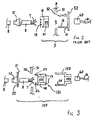
- a patch panel arrangement 1 of the prior art is illustrated which takes the form of a rack 2 on which are mounted eight patch panels 3 (indicated in sequence 3A, 3B, 3C, 7-8 etc.). One of the patch panels 3C is shown removed from the rack. Each of the patch panels has a plurality of apertures 4 punched therein and each aperture 4 is arranged to take a cable terminating device 5 to which the individual wires 7 of a cable 8 are terminated.
- the cable terminating device 5 is normally of a two part construction having a main body 51 and a front cover 52. Illustrated in phantom in Fig. 1 is a cable tidy tray 10 to which the cable 8, and other cables (not illustrated) connecting to the patch panel 3C can be secured by means of cable ties (not illustrated), or equivalent arrangements.
- the cable 8 passes through a cuff or boot 12 and is connected to the main body 51 by means of wiring contacts 13.
- the patch panel 3C has a front face 31 and a rear face 32.
- a front cover 52 is provided with two pairs of snap engaging ramps 15 and 16 respectively.
- the snap engaging ramps 15 enable the front cover 52 to be pushed into the aperture 4 and snap engaged with the patch panel 3C.
- the snap engaging ramps 16 cooperate with corresponding indentations 18 which therefore enables the main body 51 to be snap engaged with the front cover 52.
- the cable terminating device 5 has a socket 53 which is connected to the wiring contacts 13.
- the socket 53 is able to mate with a plug 60 which terminates one end of a lead 61. The entire arrangement enables the cable 8 to be electrically connected to the lead 61.
- FIG. 3 A schematic embodiment which substantially overcomes the difficulties of the prior art is illustrated in Fig. 3 .
- the wires 7, cable 8, plug 60 and lead 61 are as in Fig. 2 .
- a cuff or boot 112 is provided with a plate 21 having apertures 22 which are able to receive prongs 23 on the main body 151 of the cable terminating device 105.
- the prongs 23 are provided with ramps 24 to enable a snap engagement mechanism.
- the cable terminating device 105 is provided with a front cover 152 having ramps 115 which engage with indentations 118 in the main body 15. With the ramps 115 engaged with the indentations 118, the front cover 152 is not only engaged with the main body 151, but the inter-engaged parts are held in the aperture 4 because the patch panel 3C is clamped between the plate 21 and the front cover 152.
- the wiring contacts 113 are provided on the front surface of the main body 151 and the main body 151 has an opening 55 through which the wires 7 are led before being connected to the wiring contacts 13.
- the front cover 152 has the socket 153 (eg RJ45 or similar) which engages the plug 60 and completes the interconnection.
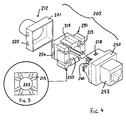
- the cable terminating device 205 has a boot or cuff 212, a main body 251 and a front cover 252.
- the boot or cuff 212 includes a housing 221 having apertures 222 which engage with ramps 224 on the main body 251. In this way the patch panel 3 is clamped between the housing 221 and the main body 251.
- the main body 251 has an opening 255 around which are radially arranged channels 213 which each include an insulation stripping and contact forming cutting blade (not illustrated) which is itself well known in the electrical connection arts.
- the main body 251 also has ramps 215 which engage with corresponding apertures 218 in the front cover 252.
- the front cover 252 is also provided with a conventional socket 253 the internal contacts of which (not illustrated) are connected to corresponding blades 260 which each enter a corresponding one of the channels 213.
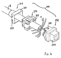
- the cable terminating device 205 can be installed on the patch panel 3 by inter-engagement of the cuff or boot 212 and the main body 251.
- the cable 8 can be pushed through the cuff or boot 212 and through the opening 255 of the main body 251.
- the wires 7 can be radially splayed as schematically illustrated in Fig. 6 and brought into the corresponding channels 213 so as to effect the making of the wiring contacts between the wires 7 and the main body 251. Any excess wire is then trimmed so as to enable the front cover 252 to be snap engaged with the main body 251 thereby driving the blades 260 into the corresponding channels 213. This forms the electrical interconnections between the socket 253 and the wires 7.
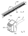
- each of the cable terminating devices 205 can be grouped together, preferably in collections of eight. Each such group is covered by a flashing plate 230 which is merely cosmetic.
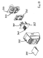
- a third embodiment is illustrated in Figs. 8-13 .
- a patch panel 303 is illustrated containing twenty four cable terminating devices 305.
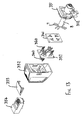
- One of the cable terminating devices 305 is illustrated in assembled form in Fig. 9 and in exploded perspective views in Figs. 10-13 .
- the cable terminating device 305 has a front cover 352 with a female socket 353 of conventional configuration which receives a conventional male plug 354.
- the main body 351 has a removable lid 355 which permits access to a slot for a screwdriver to permit the front cover to be detached from the main body 351.
- the lid 355 is used to label the terminal device 305 corresponding to the cable installed in the terminal device.
- a contactor plate 357 Housed within the front cover 352 is a contactor plate 357 which has contacts 340 on its front side which engage the plug 354, and knife blades 360 on its rear side which make the electrical contacts with the wires 7 of the cable 8.
- An apertured cover plate 341 retains the contactor plate 357 engaged with the front cover 352.
- the cable 8 is passed from the rear through the cuff 312. Then the individual wires 7 of the cable 8 are located in respective channels 313 which correspond to the knife blades 360.
- the channels 313 and knife blades 360 preferably have a generally X-shaped layout which makes it easy to place the wires 7 in the desired corresponding one of the channels 313. With the wires 7 located in the channels 313 re-connecting the front cover 352 with the main body 351 results in the knife blades 360 cutting through the installation of the wires 7 and making the desired electrical connections. As before, removal of the front cover 352 from the front of the patch panel 303 enables these wiring connections to be changed without any need to access the rear of the patch panel 303.
- the main body 151, 251 can be arcuate in shape so that the opening 55, 255 is slot shaped rather than being tubular as illustrated.
Abstract
Description
- The present invention relates to patch panel arrangements, the devices used to terminate cables in patch panels, and methods of terminating wires of cables leading to patch panels.
- Patch panels are widely used in light current electrical engineering and in data and telecommunications applications, in particular, to enable interconnections to be made which may need to be changed in future. Typical reasons for future changes include changes to the configuration of computer and other data systems, expansion of the number of telephone outlets provided at a given premises, and the like.
- Patch panels are typically mounted in racks or equivalent mounting structures such as cabinets or other housings having a door or pivoted front panel. Typically the panels are of a standard size and numerous panels are provided stacked one upon the other in a parallel relationship. Each panel has a series of apertures which are normally punched or drilled through the panel and each aperture holds a terminating device which normally takes the form of a multi-contact socket. The openings of the sockets are substantially flush with the front face of the panel. The cables which are connected to the sockets are connected by wiring contacts which are accessible only from the rear face of the patch panel. The rear face of the patch panel often includes a cable tidy or similar tray like device to which the ends of the cable adjacent to the patch panel are connected.
- As the number of cables connected to a particular patch panel increases, or the number of cables connected to adjacent patch panels increase, so it becomes increasingly difficult to access the wiring contacts at the rear face of a patch panel to make a further connection, or a number of further connections. This is a fundamental a problem which arises because the volume or space to the rear of the patch panel becomes increasingly congested and filled with cables, cable tidy trays, etc all of which restrict access to the rear of the patch panel. This is a particular problem where the patch panel may be nearly full and yet at some time after the initial installation some further connections are required.
- The genesis of the present invention is a desire to substantially overcome, or at least ameliorate, the abovementioned difficulty by providing access to the wiring contacts from the front of the patch panel.
- In accordance with a first aspect of the present invention there is disclosed a patch panel arrangement comprising at least one panel having a front face and a rear face, and having at least one aperture therethrough and means to mount the panel in a rack or equivalent mounting structure, wherein said aperture has a cable terminating device therein having wiring contacts accessible from said panel front face.
- In accordance with a second aspect of the present invention there is disclosed a cable terminating device for a patch panel having a front face and a rear face, said device comprising a first member which abuts said rear face, a second member which abuts said front face, and said second member having wiring contacts accessible from said panel front face.
- In accordance with a third aspect of the present invention there is disclosed a method of terminating wires of a cable onto a cable terminating device mounted in an aperture of a patch panel having a rear face and a front face, said method comprising the steps of:
- passing said cable from the rear of said patch panel through a cable opening provided in said terminating device; and
- terminating the wires of said cable in wiring contacts of said device accessible from said patch panel front face.
- Some embodiments of the invention will now be described, with reference to the accompanying drawings in which:
-
Fig. 1 is a perspective view of the front of a prior art patch panel arrangement, the individual patch panels being mounted in a rack; -
Fig. 2 is a schematic exploded cross-sectional view through the patch panel ofFig. 1 ; -
Fig. 3 is a view equivalent toFig. 2 but illustrating schematically the arrangement of a first embodiment of the present invention; -
Fig. 4 is a schematic exploded perspective view of a cable terminating device in accordance with a second embodiment of the present invention; -
Fig. 5 is a front view of the wiring contacts illustrated inFig. 4 ; -
Fig. 6 is an exploded perspective view similar toFig. 4 but illustrating the method of connecting the wires of the cable; -
Fig. 7 is a perspective view, partly exploded, of a patch panel fabricated in accordance with the second embodiment of the present invention; -
Fig. 8 is a perspective view of a patch panel fabricated in accordance with a third embodiment of the present invention; -
Fig. 9 is a perspective view of the cable terminating device of the third embodiment; -
Fig. 10 is an exploded perspective view from the front of the cable terminating device ofFig. 9 ; -
Fig. 11 is the same view of the cable terminating device as inFig. 10 but illustrating the cable inserted from the rear with the wiring contacts about to be made; -
Fig. 12 is an exploded perspective view of the cable terminating device offigure 9 but illustrated from the rear; and -
Fig. 13 is the same view of the cable terminating device as inFig. 12 but illustrating the cable inserted from the rear with the wiring contacts about to be made. - As seen in
Fig. 1 , a patch panel arrangement 1 of the prior art is illustrated which takes the form of a rack 2 on which are mounted eight patch panels 3 (indicated insequence patch panels 3C is shown removed from the rack. Each of the patch panels has a plurality ofapertures 4 punched therein and eachaperture 4 is arranged to take acable terminating device 5 to which theindividual wires 7 of acable 8 are terminated. - As seen in
Fig. 1 , thecable terminating device 5 is normally of a two part construction having amain body 51 and afront cover 52. Illustrated in phantom inFig. 1 is acable tidy tray 10 to which thecable 8, and other cables (not illustrated) connecting to thepatch panel 3C can be secured by means of cable ties (not illustrated), or equivalent arrangements. - Turning now to
Fig. 2 , thecable 8 passes through a cuff or boot 12 and is connected to themain body 51 by means ofwiring contacts 13. Thepatch panel 3C has afront face 31 and arear face 32. Afront cover 52 is provided with two pairs ofsnap engaging ramps snap engaging ramps 15 enable thefront cover 52 to be pushed into theaperture 4 and snap engaged with thepatch panel 3C. Thesnap engaging ramps 16 cooperate withcorresponding indentations 18 which therefore enables themain body 51 to be snap engaged with thefront cover 52. Thecable terminating device 5 has asocket 53 which is connected to thewiring contacts 13. Thesocket 53 is able to mate with aplug 60 which terminates one end of a lead 61. The entire arrangement enables thecable 8 to be electrically connected to the lead 61. - It will be appreciated from
Figs. 1 and2 that thewiring contacts 13 are only accessible from the rear of thepatch panel 3 and this makes accessing thewiring contacts 13 to make each subsequent connection increasingly more and more difficult as the volume to the rear of thepatch panels 3 increasingly becomes filled withcables 8. - A schematic embodiment which substantially overcomes the difficulties of the prior art is illustrated in
Fig. 3 . Thewires 7,cable 8,plug 60 and lead 61 are as inFig. 2 . A cuff orboot 112 is provided with aplate 21 havingapertures 22 which are able to receiveprongs 23 on themain body 151 of thecable terminating device 105. Theprongs 23 are provided withramps 24 to enable a snap engagement mechanism. - The
cable terminating device 105 is provided with afront cover 152 havingramps 115 which engage withindentations 118 in themain body 15. With theramps 115 engaged with theindentations 118, thefront cover 152 is not only engaged with themain body 151, but the inter-engaged parts are held in theaperture 4 because thepatch panel 3C is clamped between theplate 21 and thefront cover 152. - Importantly, the wiring contacts 113 are provided on the front surface of the
main body 151 and themain body 151 has anopening 55 through which thewires 7 are led before being connected to thewiring contacts 13. Thefront cover 152 has the socket 153 (eg RJ45 or similar) which engages theplug 60 and completes the interconnection. - Turning now to
Figs. 4 to 7 , a second embodiment of thecable terminating device 205 is illustrated. Thecable terminating device 205 has a boot orcuff 212, amain body 251 and afront cover 252. The boot orcuff 212 includes ahousing 221 havingapertures 222 which engage withramps 224 on themain body 251. In this way thepatch panel 3 is clamped between thehousing 221 and themain body 251. - As before, the
main body 251 has anopening 255 around which are radially arrangedchannels 213 which each include an insulation stripping and contact forming cutting blade (not illustrated) which is itself well known in the electrical connection arts. - The
main body 251 also hasramps 215 which engage withcorresponding apertures 218 in thefront cover 252. Thefront cover 252 is also provided with aconventional socket 253 the internal contacts of which (not illustrated) are connected to correspondingblades 260 which each enter a corresponding one of thechannels 213. - From
Fig. 6 it will be apparent that thecable terminating device 205 can be installed on thepatch panel 3 by inter-engagement of the cuff orboot 212 and themain body 251. In this condition with thefront cover 252 removed, thecable 8 can be pushed through the cuff orboot 212 and through theopening 255 of themain body 251. Thereafter, thewires 7 can be radially splayed as schematically illustrated inFig. 6 and brought into the correspondingchannels 213 so as to effect the making of the wiring contacts between thewires 7 and themain body 251. Any excess wire is then trimmed so as to enable thefront cover 252 to be snap engaged with themain body 251 thereby driving theblades 260 into the correspondingchannels 213. This forms the electrical interconnections between thesocket 253 and thewires 7. - Turning now to
Fig. 7 , it will be seen that each of thecable terminating devices 205 can be grouped together, preferably in collections of eight. Each such group is covered by a flashingplate 230 which is merely cosmetic. - It will be apparent to those skilled in the art that an additional cable can be installed onto the patch panel illustrated in
Fig. 7 at any time, without removing the patch panel from its rack or cabinet. Instead, all that is required to be done from the inside of the rack or cabinet is to push the new cable through the cuff or boot 212 of the correspondingcable terminating device 205. Thereafter, with the flashingplate 230 and thefront cover 252 removed, access from the front of the patch panel can be had to thechannels 213 containing the wiring contacts and therefore the actual making of the contacts takes place from the front side of the patch panel. Since this work area is entirely uncluttered, ease of operation and assembly so as to make the necessary contacts is ensured, irrespective of the presence or absence of cable connections already made to adjacent cable terminating devices. - A third embodiment is illustrated in
Figs. 8-13 . Apatch panel 303 is illustrated containing twenty fourcable terminating devices 305. One of thecable terminating devices 305 is illustrated in assembled form inFig. 9 and in exploded perspective views inFigs. 10-13 . Thecable terminating device 305 has afront cover 352 with afemale socket 353 of conventional configuration which receives a conventionalmale plug 354. Themain body 351 has aremovable lid 355 which permits access to a slot for a screwdriver to permit the front cover to be detached from themain body 351. - The
lid 355 is used to label theterminal device 305 corresponding to the cable installed in the terminal device. - Housed within the
front cover 352 is acontactor plate 357 which hascontacts 340 on its front side which engage theplug 354, andknife blades 360 on its rear side which make the electrical contacts with thewires 7 of thecable 8. Anapertured cover plate 341 retains thecontactor plate 357 engaged with thefront cover 352. - The
cable 8 is passed from the rear through thecuff 312. Then theindividual wires 7 of thecable 8 are located inrespective channels 313 which correspond to theknife blades 360. Thechannels 313 andknife blades 360 preferably have a generally X-shaped layout which makes it easy to place thewires 7 in the desired corresponding one of thechannels 313. With thewires 7 located in thechannels 313 re-connecting thefront cover 352 with themain body 351 results in theknife blades 360 cutting through the installation of thewires 7 and making the desired electrical connections. As before, removal of thefront cover 352 from the front of thepatch panel 303 enables these wiring connections to be changed without any need to access the rear of thepatch panel 303. - The foregoing describes only some embodiments of the present invention and modifications, obvious to those skilled in the electrical wiring arts, can be made thereto without departing from the scope of the present invention. For example, the
main body opening - The term "comprising" (and its grammatical variations) as used herein is used in the inclusive sense of "including" or "having" and not in the exclusive sense of "consisting only of".
Claims (18)
- A patch panel arrangement comprising at least one panel (3) having a front face (31) and a rear face (32), and having at least one aperture (4) therethrough and means to mount the panel in a rack (2) or equivalent mounting structure, characterised in that said aperture has a cable terminating device (105, 205, 305) therein having wiring contacts (213, 313, 260, 360) accessible from said panel front face.
- The arrangement as claimed in claim 1 wherein said cable terminating device includes a first member (151, 251, 351, 112, 212, 312) which abuts said rear face and a second member (152, 252, 352) which abuts said front face.
- The arrangement as claimed in claim 2 wherein said first and second members include a snap engageable locking means (115, 215) to retain said first and second members engaged and thereby retained in said aperture.
- The arrangement as claimed in claim 3 wherein said first and second members are each substantially annular, each having an opening (55, 255) through which a cable (8) can pass.
- The arrangement as claimed in any one of claims 2 to 4 wherein said second member has a rear surface which abuts said panel front face and a front surface which includes said wiring contacts (213, 313).
- The arrangement as claimed in claim 5 wherein said second member engages with a connector body (252, 352) which substantially covers said wiring contacts.
- The arrangement as claimed in claim 6 wherein said connector body is provided with an outer cover (230).
- The arrangement as claimed in claim 6 or 7 wherein said connector body comprises a female socket (153, 253, 353).
- The arrangement as claimed in any one of claims 1 to 8 wherein said cable terminating device is a data or communications connector.
- A cable terminating device for a patch panel having a front face (31) and a rear face (41), said device (105, 205, 305) comprising a first member (151, 251, 351, 112, 212, 312) which abuts said rear face, a second member (152, 252, 352) which abuts said front face, and said second member having wiring contacts (213, 313, 260, 360) accessible from said panel front face.
- The device as claimed in claim 10 wherein said first and second members include a snap engageable locking means (115, 215) to retain said first and second members engaged and thereby retain said device in an aperture (4) of said patch panel.
- The device as claimed in claim 10 or 11 wherein said first and second members are each substantially annular, each having an opening (55, 255) through which a cable (8) can pass.
- The device as claimed in any one of claims 10 to 12 wherein said second member has a rear surface which abuts said panel front face and a front surface which includes said wiring contacts (213,313).
- The device as claimed in claim 13 wherein said second member engages with a connector body (252, 352) which substantially covers said wiring contacts.
- The device as claimed in claim 14 wherein said connector body is provided with an outer cover (230).
- The device as claimed in claim 14 or 15 wherein said connector body comprises a female socket (153, 253, 353).
- The device as claimed in any one of claims 10 to 16 and comprising a data or communications connector.
- A method of terminating wires (7) of a cable (8) onto a cable terminating device (105, 205, 305) mounted in an aperture (4) of a patch panel (3) having a rear face (32) and a front face (31), said method comprising the steps of:passing said cable from the rear of said patch panel through a cable opening (55, 255) provided in said terminating device; andterminating the wires of said cable in wiring contacts (213, 313, 260, 360) of said device accessible from said patch panel front face.
Applications Claiming Priority (1)
| Application Number | Priority Date | Filing Date | Title |
|---|---|---|---|
| AU2013901778A AU2013901778A0 (en) | 2013-05-20 | Patch Panel Arrangements, Cable Terminating Devices and Methods |
Publications (2)
| Publication Number | Publication Date |
|---|---|
| EP2806653A1 true EP2806653A1 (en) | 2014-11-26 |
| EP2806653B1 EP2806653B1 (en) | 2018-02-14 |
Family
ID=50927868
Family Applications (1)
| Application Number | Title | Priority Date | Filing Date |
|---|---|---|---|
| EP14001760.9A Active EP2806653B1 (en) | 2013-05-20 | 2014-05-19 | Patch panel arrangement, cable terminating device and method |
Country Status (4)
| Country | Link |
|---|---|
| US (1) | US9281576B2 (en) |
| EP (1) | EP2806653B1 (en) |
| AU (5) | AU2014202653A1 (en) |
| ES (1) | ES2668622T3 (en) |
Cited By (1)
| Publication number | Priority date | Publication date | Assignee | Title |
|---|---|---|---|---|
| EP3823107A1 (en) * | 2019-11-13 | 2021-05-19 | Corning Research & Development Corporation | Telecommunication wall outlet and method for installing the same |
Families Citing this family (1)
| Publication number | Priority date | Publication date | Assignee | Title |
|---|---|---|---|---|
| CN204693230U (en) * | 2015-05-29 | 2015-10-07 | 深圳市洲明科技股份有限公司 | LED lamp affixed to the ceiling |
Citations (3)
| Publication number | Priority date | Publication date | Assignee | Title |
|---|---|---|---|---|
| EP0575072A1 (en) * | 1992-06-11 | 1993-12-22 | AT&T Corp. | Universal patch panel for electrical communications use in buildings |
| WO2011083470A1 (en) * | 2010-01-07 | 2011-07-14 | Rit Technologies Ltd. | A modular connector for a cable-less patching device |
| US20110195598A1 (en) * | 2007-12-11 | 2011-08-11 | Panella Augusto P | Termination Cap For Use In Wired Network Management System |
Family Cites Families (8)
| Publication number | Priority date | Publication date | Assignee | Title |
|---|---|---|---|---|
| US6302728B1 (en) * | 1998-12-29 | 2001-10-16 | Avaya Technology Corp. | Patch panel with reverse cordage exit patch cord |
| US20080124971A1 (en) * | 2006-01-06 | 2008-05-29 | Hoelzel Richard A | Service provider patch panel assembly |
| WO2010042591A1 (en) * | 2008-10-07 | 2010-04-15 | Molex Incorporated | Improved patch panel assembly for use with data networks |
| US7762839B2 (en) * | 2008-12-22 | 2010-07-27 | Surtec Industries, Inc. | Patch panel assembly |
| US9007206B2 (en) * | 2010-01-29 | 2015-04-14 | Surtec Industries, Inc. | Patch panel and intelligent structured cabling system |
| US8025514B1 (en) * | 2010-04-23 | 2011-09-27 | Leviton Manufacturing Co., Inc. | Shroud to prevent manipulation of a release mechanism of a plug |
| US8638651B2 (en) * | 2011-01-21 | 2014-01-28 | Commscope, Inc. Of North Carolina | Intelligent patching systems and methods using phantom mode control signals and related communications connectors |
| JP6216328B2 (en) * | 2012-01-27 | 2017-10-18 | ゴーフォトン・ホールディングス,インコーポレイテッド | Patch panel assembly |
-
2014
- 2014-05-15 AU AU2014202653A patent/AU2014202653A1/en not_active Abandoned
- 2014-05-19 EP EP14001760.9A patent/EP2806653B1/en active Active
- 2014-05-19 ES ES14001760.9T patent/ES2668622T3/en active Active
- 2014-05-20 US US14/282,019 patent/US9281576B2/en not_active Expired - Fee Related
-
2017
- 2017-06-28 AU AU2017204380A patent/AU2017204380A1/en not_active Abandoned
-
2019
- 2019-01-11 AU AU2019200197A patent/AU2019200197A1/en not_active Abandoned
-
2020
- 2020-12-17 AU AU2020289801A patent/AU2020289801A1/en not_active Abandoned
-
2022
- 2022-07-27 AU AU2022209270A patent/AU2022209270A1/en not_active Abandoned
Patent Citations (3)
| Publication number | Priority date | Publication date | Assignee | Title |
|---|---|---|---|---|
| EP0575072A1 (en) * | 1992-06-11 | 1993-12-22 | AT&T Corp. | Universal patch panel for electrical communications use in buildings |
| US20110195598A1 (en) * | 2007-12-11 | 2011-08-11 | Panella Augusto P | Termination Cap For Use In Wired Network Management System |
| WO2011083470A1 (en) * | 2010-01-07 | 2011-07-14 | Rit Technologies Ltd. | A modular connector for a cable-less patching device |
Cited By (1)
| Publication number | Priority date | Publication date | Assignee | Title |
|---|---|---|---|---|
| EP3823107A1 (en) * | 2019-11-13 | 2021-05-19 | Corning Research & Development Corporation | Telecommunication wall outlet and method for installing the same |
Also Published As
| Publication number | Publication date |
|---|---|
| US9281576B2 (en) | 2016-03-08 |
| US20140342603A1 (en) | 2014-11-20 |
| EP2806653B1 (en) | 2018-02-14 |
| ES2668622T3 (en) | 2018-05-21 |
| AU2020289801A1 (en) | 2021-01-28 |
| AU2017204380A1 (en) | 2017-07-20 |
| AU2019200197A1 (en) | 2019-01-31 |
| AU2014202653A1 (en) | 2014-12-04 |
| AU2022209270A1 (en) | 2022-08-25 |
Similar Documents
| Publication | Publication Date | Title |
|---|---|---|
| US11715920B2 (en) | Single pair ethernet connector system | |
| EP1754288B1 (en) | Interface adapter module | |
| US6945815B1 (en) | Quick connect electrical outlet | |
| CN219696714U (en) | Contact for communication connector and communication connector | |
| AU2022209270A1 (en) | Patch panel arrangements cable terminating devices & methods | |
| US8650750B2 (en) | Process for assembling a data cable connector module | |
| US9583885B2 (en) | Connector assembly with grounding spring | |
| EP3847720A1 (en) | Field terminable single pair ethernet connector | |
| US9865960B2 (en) | Coupler connector and cable terminator with side contacts | |
| US8608490B2 (en) | Modular wiring system | |
| US7037118B2 (en) | Access module | |
| US9692195B2 (en) | No-touch busway plug in units | |
| US20050124195A1 (en) | Selectable receptacle | |
| US7804026B2 (en) | Enclosure for wiring devices | |
| US10490960B1 (en) | Field termination network plug | |
| IL43381A (en) | Multi-conductor cable connector apparatus for telephone and other data transmission systems | |
| CA2935842A1 (en) | Doorless modular panelboard | |
| US20210021076A1 (en) | Single Pair Ethernet Connector | |
| KR100758922B1 (en) | Improved electrical junction box | |
| EP3767766B1 (en) | Electric or electronic device | |
| KR20090049243A (en) | Wire connecting device and wire connecting method using the device | |
| US7150656B1 (en) | Digital switching cross-connect module | |
| GB2218865A (en) | Plug and socket outlet system |
Legal Events
| Date | Code | Title | Description |
|---|---|---|---|
| PUAI | Public reference made under article 153(3) epc to a published international application that has entered the european phase |
Free format text: ORIGINAL CODE: 0009012 |
|
| 17P | Request for examination filed |
Effective date: 20140519 |
|
| AK | Designated contracting states |
Kind code of ref document: A1 Designated state(s): AL AT BE BG CH CY CZ DE DK EE ES FI FR GB GR HR HU IE IS IT LI LT LU LV MC MK MT NL NO PL PT RO RS SE SI SK SM TR |
|
| AX | Request for extension of the european patent |
Extension state: BA ME |
|
| R17P | Request for examination filed (corrected) |
Effective date: 20150515 |
|
| GRAP | Despatch of communication of intention to grant a patent |
Free format text: ORIGINAL CODE: EPIDOSNIGR1 |
|
| INTG | Intention to grant announced |
Effective date: 20171016 |
|
| GRAS | Grant fee paid |
Free format text: ORIGINAL CODE: EPIDOSNIGR3 |
|
| GRAA | (expected) grant |
Free format text: ORIGINAL CODE: 0009210 |
|
| AK | Designated contracting states |
Kind code of ref document: B1 Designated state(s): AL AT BE BG CH CY CZ DE DK EE ES FI FR GB GR HR HU IE IS IT LI LT LU LV MC MK MT NL NO PL PT RO RS SE SI SK SM TR |
|
| REG | Reference to a national code |
Ref country code: GB Ref legal event code: FG4D |
|
| REG | Reference to a national code |
Ref country code: CH Ref legal event code: EP |
|
| REG | Reference to a national code |
Ref country code: IE Ref legal event code: FG4D |
|
| REG | Reference to a national code |
Ref country code: DE Ref legal event code: R096 Ref document number: 602014020854 Country of ref document: DE Ref country code: AT Ref legal event code: REF Ref document number: 970600 Country of ref document: AT Kind code of ref document: T Effective date: 20180315 |
|
| REG | Reference to a national code |
Ref country code: FR Ref legal event code: PLFP Year of fee payment: 5 |
|
| REG | Reference to a national code |
Ref country code: ES Ref legal event code: FG2A Ref document number: 2668622 Country of ref document: ES Kind code of ref document: T3 Effective date: 20180521 |
|
| REG | Reference to a national code |
Ref country code: NL Ref legal event code: FP |
|
| REG | Reference to a national code |
Ref country code: AT Ref legal event code: MK05 Ref document number: 970600 Country of ref document: AT Kind code of ref document: T Effective date: 20180214 |
|
| PG25 | Lapsed in a contracting state [announced via postgrant information from national office to epo] |
Ref country code: FI Free format text: LAPSE BECAUSE OF FAILURE TO SUBMIT A TRANSLATION OF THE DESCRIPTION OR TO PAY THE FEE WITHIN THE PRESCRIBED TIME-LIMIT Effective date: 20180214 Ref country code: HR Free format text: LAPSE BECAUSE OF FAILURE TO SUBMIT A TRANSLATION OF THE DESCRIPTION OR TO PAY THE FEE WITHIN THE PRESCRIBED TIME-LIMIT Effective date: 20180214 Ref country code: NO Free format text: LAPSE BECAUSE OF FAILURE TO SUBMIT A TRANSLATION OF THE DESCRIPTION OR TO PAY THE FEE WITHIN THE PRESCRIBED TIME-LIMIT Effective date: 20180514 Ref country code: CY Free format text: LAPSE BECAUSE OF FAILURE TO SUBMIT A TRANSLATION OF THE DESCRIPTION OR TO PAY THE FEE WITHIN THE PRESCRIBED TIME-LIMIT Effective date: 20180214 Ref country code: LT Free format text: LAPSE BECAUSE OF FAILURE TO SUBMIT A TRANSLATION OF THE DESCRIPTION OR TO PAY THE FEE WITHIN THE PRESCRIBED TIME-LIMIT Effective date: 20180214 |
|
| PG25 | Lapsed in a contracting state [announced via postgrant information from national office to epo] |
Ref country code: BG Free format text: LAPSE BECAUSE OF FAILURE TO SUBMIT A TRANSLATION OF THE DESCRIPTION OR TO PAY THE FEE WITHIN THE PRESCRIBED TIME-LIMIT Effective date: 20180514 Ref country code: GR Free format text: LAPSE BECAUSE OF FAILURE TO SUBMIT A TRANSLATION OF THE DESCRIPTION OR TO PAY THE FEE WITHIN THE PRESCRIBED TIME-LIMIT Effective date: 20180515 Ref country code: RS Free format text: LAPSE BECAUSE OF FAILURE TO SUBMIT A TRANSLATION OF THE DESCRIPTION OR TO PAY THE FEE WITHIN THE PRESCRIBED TIME-LIMIT Effective date: 20180214 Ref country code: LV Free format text: LAPSE BECAUSE OF FAILURE TO SUBMIT A TRANSLATION OF THE DESCRIPTION OR TO PAY THE FEE WITHIN THE PRESCRIBED TIME-LIMIT Effective date: 20180214 Ref country code: SE Free format text: LAPSE BECAUSE OF FAILURE TO SUBMIT A TRANSLATION OF THE DESCRIPTION OR TO PAY THE FEE WITHIN THE PRESCRIBED TIME-LIMIT Effective date: 20180214 Ref country code: AT Free format text: LAPSE BECAUSE OF FAILURE TO SUBMIT A TRANSLATION OF THE DESCRIPTION OR TO PAY THE FEE WITHIN THE PRESCRIBED TIME-LIMIT Effective date: 20180214 |
|
| PG25 | Lapsed in a contracting state [announced via postgrant information from national office to epo] |
Ref country code: EE Free format text: LAPSE BECAUSE OF FAILURE TO SUBMIT A TRANSLATION OF THE DESCRIPTION OR TO PAY THE FEE WITHIN THE PRESCRIBED TIME-LIMIT Effective date: 20180214 Ref country code: AL Free format text: LAPSE BECAUSE OF FAILURE TO SUBMIT A TRANSLATION OF THE DESCRIPTION OR TO PAY THE FEE WITHIN THE PRESCRIBED TIME-LIMIT Effective date: 20180214 Ref country code: RO Free format text: LAPSE BECAUSE OF FAILURE TO SUBMIT A TRANSLATION OF THE DESCRIPTION OR TO PAY THE FEE WITHIN THE PRESCRIBED TIME-LIMIT Effective date: 20180214 Ref country code: PL Free format text: LAPSE BECAUSE OF FAILURE TO SUBMIT A TRANSLATION OF THE DESCRIPTION OR TO PAY THE FEE WITHIN THE PRESCRIBED TIME-LIMIT Effective date: 20180214 |
|
| REG | Reference to a national code |
Ref country code: DE Ref legal event code: R097 Ref document number: 602014020854 Country of ref document: DE |
|
| PG25 | Lapsed in a contracting state [announced via postgrant information from national office to epo] |
Ref country code: CZ Free format text: LAPSE BECAUSE OF FAILURE TO SUBMIT A TRANSLATION OF THE DESCRIPTION OR TO PAY THE FEE WITHIN THE PRESCRIBED TIME-LIMIT Effective date: 20180214 Ref country code: SK Free format text: LAPSE BECAUSE OF FAILURE TO SUBMIT A TRANSLATION OF THE DESCRIPTION OR TO PAY THE FEE WITHIN THE PRESCRIBED TIME-LIMIT Effective date: 20180214 Ref country code: DK Free format text: LAPSE BECAUSE OF FAILURE TO SUBMIT A TRANSLATION OF THE DESCRIPTION OR TO PAY THE FEE WITHIN THE PRESCRIBED TIME-LIMIT Effective date: 20180214 Ref country code: SM Free format text: LAPSE BECAUSE OF FAILURE TO SUBMIT A TRANSLATION OF THE DESCRIPTION OR TO PAY THE FEE WITHIN THE PRESCRIBED TIME-LIMIT Effective date: 20180214 |
|
| REG | Reference to a national code |
Ref country code: CH Ref legal event code: PL |
|
| PLBE | No opposition filed within time limit |
Free format text: ORIGINAL CODE: 0009261 |
|
| STAA | Information on the status of an ep patent application or granted ep patent |
Free format text: STATUS: NO OPPOSITION FILED WITHIN TIME LIMIT |
|
| 26N | No opposition filed |
Effective date: 20181115 |
|
| REG | Reference to a national code |
Ref country code: BE Ref legal event code: MM Effective date: 20180531 |
|
| PG25 | Lapsed in a contracting state [announced via postgrant information from national office to epo] |
Ref country code: MC Free format text: LAPSE BECAUSE OF FAILURE TO SUBMIT A TRANSLATION OF THE DESCRIPTION OR TO PAY THE FEE WITHIN THE PRESCRIBED TIME-LIMIT Effective date: 20180214 |
|
| REG | Reference to a national code |
Ref country code: IE Ref legal event code: MM4A |
|
| PG25 | Lapsed in a contracting state [announced via postgrant information from national office to epo] |
Ref country code: SI Free format text: LAPSE BECAUSE OF FAILURE TO SUBMIT A TRANSLATION OF THE DESCRIPTION OR TO PAY THE FEE WITHIN THE PRESCRIBED TIME-LIMIT Effective date: 20180214 Ref country code: LI Free format text: LAPSE BECAUSE OF NON-PAYMENT OF DUE FEES Effective date: 20180531 Ref country code: CH Free format text: LAPSE BECAUSE OF NON-PAYMENT OF DUE FEES Effective date: 20180531 |
|
| PG25 | Lapsed in a contracting state [announced via postgrant information from national office to epo] |
Ref country code: LU Free format text: LAPSE BECAUSE OF NON-PAYMENT OF DUE FEES Effective date: 20180519 |
|
| PG25 | Lapsed in a contracting state [announced via postgrant information from national office to epo] |
Ref country code: IE Free format text: LAPSE BECAUSE OF NON-PAYMENT OF DUE FEES Effective date: 20180519 |
|
| PG25 | Lapsed in a contracting state [announced via postgrant information from national office to epo] |
Ref country code: BE Free format text: LAPSE BECAUSE OF NON-PAYMENT OF DUE FEES Effective date: 20180531 |
|
| PG25 | Lapsed in a contracting state [announced via postgrant information from national office to epo] |
Ref country code: MT Free format text: LAPSE BECAUSE OF NON-PAYMENT OF DUE FEES Effective date: 20180519 |
|
| PG25 | Lapsed in a contracting state [announced via postgrant information from national office to epo] |
Ref country code: TR Free format text: LAPSE BECAUSE OF FAILURE TO SUBMIT A TRANSLATION OF THE DESCRIPTION OR TO PAY THE FEE WITHIN THE PRESCRIBED TIME-LIMIT Effective date: 20180214 |
|
| PG25 | Lapsed in a contracting state [announced via postgrant information from national office to epo] |
Ref country code: HU Free format text: LAPSE BECAUSE OF FAILURE TO SUBMIT A TRANSLATION OF THE DESCRIPTION OR TO PAY THE FEE WITHIN THE PRESCRIBED TIME-LIMIT; INVALID AB INITIO Effective date: 20140519 Ref country code: PT Free format text: LAPSE BECAUSE OF FAILURE TO SUBMIT A TRANSLATION OF THE DESCRIPTION OR TO PAY THE FEE WITHIN THE PRESCRIBED TIME-LIMIT Effective date: 20180214 |
|
| PG25 | Lapsed in a contracting state [announced via postgrant information from national office to epo] |
Ref country code: MK Free format text: LAPSE BECAUSE OF NON-PAYMENT OF DUE FEES Effective date: 20180214 |
|
| PG25 | Lapsed in a contracting state [announced via postgrant information from national office to epo] |
Ref country code: IS Free format text: LAPSE BECAUSE OF FAILURE TO SUBMIT A TRANSLATION OF THE DESCRIPTION OR TO PAY THE FEE WITHIN THE PRESCRIBED TIME-LIMIT Effective date: 20180614 |
|
| PGFP | Annual fee paid to national office [announced via postgrant information from national office to epo] |
Ref country code: NL Payment date: 20220718 Year of fee payment: 9 |
|
| PGFP | Annual fee paid to national office [announced via postgrant information from national office to epo] |
Ref country code: IT Payment date: 20220726 Year of fee payment: 9 Ref country code: GB Payment date: 20220717 Year of fee payment: 9 Ref country code: ES Payment date: 20220725 Year of fee payment: 9 Ref country code: DE Payment date: 20220725 Year of fee payment: 9 |
|
| PGFP | Annual fee paid to national office [announced via postgrant information from national office to epo] |
Ref country code: FR Payment date: 20220721 Year of fee payment: 10 |
|
| REG | Reference to a national code |
Ref country code: DE Ref legal event code: R119 Ref document number: 602014020854 Country of ref document: DE |
|
| REG | Reference to a national code |
Ref country code: NL Ref legal event code: MM Effective date: 20230601 |
|
| GBPC | Gb: european patent ceased through non-payment of renewal fee |
Effective date: 20230519 |
|
| PG25 | Lapsed in a contracting state [announced via postgrant information from national office to epo] |
Ref country code: NL Free format text: LAPSE BECAUSE OF NON-PAYMENT OF DUE FEES Effective date: 20230601 |