EP2807826B1 - 3d zoom imager - Google Patents
3d zoom imager Download PDFInfo
- Publication number
- EP2807826B1 EP2807826B1 EP13740760.7A EP13740760A EP2807826B1 EP 2807826 B1 EP2807826 B1 EP 2807826B1 EP 13740760 A EP13740760 A EP 13740760A EP 2807826 B1 EP2807826 B1 EP 2807826B1
- Authority
- EP
- European Patent Office
- Prior art keywords
- camera
- distance
- prime
- tof
- far
- Prior art date
- Legal status (The legal status is an assumption and is not a legal conclusion. Google has not performed a legal analysis and makes no representation as to the accuracy of the status listed.)
- Active
Links
- 238000003384 imaging method Methods 0.000 claims description 24
- 230000003287 optical effect Effects 0.000 claims description 20
- 238000000034 method Methods 0.000 claims description 13
- 238000009826 distribution Methods 0.000 claims description 9
- 230000007423 decrease Effects 0.000 description 6
- 238000005259 measurement Methods 0.000 description 6
- 238000010586 diagram Methods 0.000 description 3
- 238000005315 distribution function Methods 0.000 description 2
- 238000005286 illumination Methods 0.000 description 2
- 238000009416 shuttering Methods 0.000 description 2
- 239000007787 solid Substances 0.000 description 2
- 238000001514 detection method Methods 0.000 description 1
- 229910003460 diamond Inorganic materials 0.000 description 1
- 239000010432 diamond Substances 0.000 description 1
- 230000000694 effects Effects 0.000 description 1
- 238000011156 evaluation Methods 0.000 description 1
- 231100001261 hazardous Toxicity 0.000 description 1
- 238000009434 installation Methods 0.000 description 1
- 238000012544 monitoring process Methods 0.000 description 1
- 238000012545 processing Methods 0.000 description 1
- 238000001228 spectrum Methods 0.000 description 1
- 238000012360 testing method Methods 0.000 description 1
Images

Classifications
-
- H—ELECTRICITY
- H04—ELECTRIC COMMUNICATION TECHNIQUE
- H04N—PICTORIAL COMMUNICATION, e.g. TELEVISION
- H04N13/00—Stereoscopic video systems; Multi-view video systems; Details thereof
-
- G—PHYSICS
- G01—MEASURING; TESTING
- G01S—RADIO DIRECTION-FINDING; RADIO NAVIGATION; DETERMINING DISTANCE OR VELOCITY BY USE OF RADIO WAVES; LOCATING OR PRESENCE-DETECTING BY USE OF THE REFLECTION OR RERADIATION OF RADIO WAVES; ANALOGOUS ARRANGEMENTS USING OTHER WAVES
- G01S17/00—Systems using the reflection or reradiation of electromagnetic waves other than radio waves, e.g. lidar systems
- G01S17/02—Systems using the reflection of electromagnetic waves other than radio waves
- G01S17/06—Systems determining position data of a target
- G01S17/08—Systems determining position data of a target for measuring distance only
- G01S17/10—Systems determining position data of a target for measuring distance only using transmission of interrupted, pulse-modulated waves
-
- G—PHYSICS
- G01—MEASURING; TESTING
- G01S—RADIO DIRECTION-FINDING; RADIO NAVIGATION; DETERMINING DISTANCE OR VELOCITY BY USE OF RADIO WAVES; LOCATING OR PRESENCE-DETECTING BY USE OF THE REFLECTION OR RERADIATION OF RADIO WAVES; ANALOGOUS ARRANGEMENTS USING OTHER WAVES
- G01S17/00—Systems using the reflection or reradiation of electromagnetic waves other than radio waves, e.g. lidar systems
- G01S17/87—Combinations of systems using electromagnetic waves other than radio waves
-
- G—PHYSICS
- G01—MEASURING; TESTING
- G01S—RADIO DIRECTION-FINDING; RADIO NAVIGATION; DETERMINING DISTANCE OR VELOCITY BY USE OF RADIO WAVES; LOCATING OR PRESENCE-DETECTING BY USE OF THE REFLECTION OR RERADIATION OF RADIO WAVES; ANALOGOUS ARRANGEMENTS USING OTHER WAVES
- G01S17/00—Systems using the reflection or reradiation of electromagnetic waves other than radio waves, e.g. lidar systems
- G01S17/88—Lidar systems specially adapted for specific applications
- G01S17/89—Lidar systems specially adapted for specific applications for mapping or imaging
- G01S17/894—3D imaging with simultaneous measurement of time-of-flight at a 2D array of receiver pixels, e.g. time-of-flight cameras or flash lidar
-
- H—ELECTRICITY
- H04—ELECTRIC COMMUNICATION TECHNIQUE
- H04N—PICTORIAL COMMUNICATION, e.g. TELEVISION
- H04N13/00—Stereoscopic video systems; Multi-view video systems; Details thereof
- H04N13/20—Image signal generators
- H04N13/204—Image signal generators using stereoscopic image cameras
- H04N13/239—Image signal generators using stereoscopic image cameras using two 2D image sensors having a relative position equal to or related to the interocular distance
Definitions
- an angle that the object subtends at a photosensor on which the camera images the object decreases, and a size of an image of the object that the camera projects onto the photosensor and a number of pixels in the photosensor covered by the image decreases.
- resolution of the object's features decreases and details of the object may become indiscernible.
- An optical system of a camera that provides zoom functionality is adjustable so that as an object recedes from the camera it may be "zoomed in” to conserve or increase an angle that the object subtends at the camera photosensor. Zooming in on an object magnifies an image of the object that the camera focuses onto its photosensor and improves resolution of imaged features of the object.
- Zoom adjustment for a camera is typically provided by a mechanical system that moves a lens or lenses in the camera's optical system to change the relative positions of the lenses and thereby a focal length of the optical system.
- the system moves the lenses to provide the camera with a relatively long focal length and a field of view (FOV) characterized by a relatively small view angle to zoom in on an object and magnify an image of the object that the camera acquires.
- the system moves the lenses to provide the camera with a relatively short focal length and relatively wide-angle FOV to "zoom out" the object, and demagnify the object's image that the camera acquires.
- FOV field of view
- the FOV of a camera is a region of space defined by a solid angle that extends from an optical center of the camera and for which points therein are imaged by the camera's optical system on the camera photosensor. Size of a FOV for most imaging purposes is conveniently measured by horizontal and vertical view angles. The horizontal and vertical view angles are largest angles between two lines that extend from the optical center of the camera, are contained in the FOV, and are coplanar with the camera optical axis in a plane respectively parallel and perpendicular to the ground.
- zooming in magnifies images of objects in a scene that the camera images
- zooming out demagnifies images of objects in a scene that the camera images
- it also increases the view angles of the camera's FOV and as a result increases a size of the imaged scene and a portion of an environment surrounding the camera that the camera is able to image.
- a camera that images the person image the person with an acceptable degree of resolution over a relatively large volume of space, hereinafter referred to as an "active space".
- an active space For example, to interface a person with a computer game, hereinafter also a full-body, three-dimensional (3D) game, such as a boxing game or a game requiring exercise, that responds to full body motion of the person, it can be advantageous that the camera image the person with acceptable resolution substantially everywhere in the active space.
- the active space may for example have a "length" that extends from a distance near the camera equal to about 1 m (meters) to a far distance from the camera equal to about 3 m.
- the camera optics may be configured for zoom adjustment.
- Imaging a person to track the person's gestures or motion during playing a 3D game is advantageously performed using a 3D camera, such as a triangulation or a time of flight (TOF) 3D camera, which acquires distances to features of the person and optionally features of the person's environment.
- the distances acquired by the 3D camera for the person and optionally the person's environment at a substantially same given time provides a "range image" of a scene comprising the person.
- 3D cameras are generally active illumination cameras that image a scene with light they generate and configure to determine distances to features in the scene.
- a triangulation type 3D camera acquires distances to features in a scene from angles at which the camera images the features from two, generally slightly, different perspectives.
- the triangulation camera may illuminate the scene with spatially modulated light referred to as "structured light”.
- a time of flight (TOF) 3D camera acquires distances to features in a scene that the camera images by timing how long it takes temporally modulated light that it transmits to travel to the features and back to the camera.
- the camera transmits the light generally in very short light pulses and images light from the pulses that are reflected by the features that it collects to determine round trip, that is "back and forth", travel times for light.
- DE 10 2009 045600 A1 describes a 3D camera having a pixel array on the basis of a mixing detection, implemented such that individual pixels of the pixel array can be merged to form pixel blocks.
- DE 10 2009 046108 A1 describes a camera system having at least two TOF receivers and an active lighting system, in which the two TOF receivers are arranged offset with respect to one another in order to bring about a stereo effect.
- US 2008/0273758 A1 describes that an apparatus for monitoring a spatial area, in particular for safeguarding a hazardous area of an automatically operated installation, comprises an illumination device which at least temporarily emits light signals into the spatial area.
- a first image recording unit records a first image of the spatial area.
- the first image recording unit comprises an image sensor having a plurality of pixels.
- An evaluation unit determines a distance value for at least one spatial area point, which is located in the spatial area and is imaged on at least one pixel, by means of a propagation type measurement.
- the propagation type measurement suffers from a limited unambiguity range. Therefore, a test device is designed to check the distance value by means of a reference distance value determined from a second image of said spatial area.
- An embodiment of the invention relates to providing a 3D imaging system, hereinafter also referred to as a "3D imager", comprising a first 3D camera having a wide-angle FOV that overlaps at least a portion of a narrow-angle FOV of a second 3D camera.
- the FOVs of the first and second 3D cameras define an active space of the 3D imager.
- the 3D imager comprises a processor programmed with an executable instruction set for implementing an algorithm that provides a range image of features in the active space responsive to distance information provided by the first and second 3D cameras.
- the algorithm determines distances to features in a first "near region" of the active space relatively near to the 3D imager responsive to distances determined by the first 3D camera, hereinafter also referred to as a "near camera”.
- the algorithm determines distances to features in a second "far region” of the active space relatively far from the 3D imager responsive to distances determined by the second 3D camera, hereinafter also referred to as a "far camera”.
- Distances to features in a third, “overlap" region of the active space where the FOVs of the near and far 3D cameras overlap are determined using distance information provided by both 3D cameras.
- the near and far 3D cameras comprise near and far TOF 3D cameras respectively, hereinafter also referred to as near and far TOF cameras.
- a pixel in the near or far TOF camera acquires an image, hereinafter also a "distance image", that provides a measure of distance from the TOF camera of a feature in the active space that is imaged on the pixel.
- the algorithm provides a method of correlating pixels in the TOF cameras to determine which pixels in the near or far TOF camera image a substantially same feature of the active space that is imaged by pixels in the far or near TOF camera respectively.
- the correlation is performed responsive to distance information that distance images acquired by the pixels provide.
- the correlation is performed by maximizing a probability distribution that the pixels in the different TOF cameras image a same feature in the active space.
- the 3D imager comprises a controller that controls intensity of light provided by the 3D imager to illuminate the active space responsive to distance of features in the active space that are imaged by the 3D imager.
- the 3D imager By configuring a 3D imager in accordance with an embodiment of the invention, so that it comprises near and far TOF cameras having respectively wide-angle and narrow-angle FOVs, the 3D imager has a relatively large active space.
- the 3D imager images features substantially anywhere in the space at a same relatively high spatial resolution without having to use conventional zoom optics.
- adjectives such as “substantially” and “about” modifying a condition or relationship characteristic of a feature or features of an embodiment of the invention are understood to mean that the condition or characteristic is defined to within tolerances that are acceptable for operation of the embodiment for an application for which it is intended.
- a TOF 3D imager comprising a plurality of optionally two TOF cameras
- Fig. 1 shows components of the TOF 3D imager and an active space provided by the FOVs of the TOF cameras.
- Fig. 2 schematically shows geometrical relationships between distance images acquired by pixels in the two TOF cameras for features in a same region of the active space of the TOF 3D imager shown in Fig. 1 .
- the figure schematically shows uncertainties in distance measurements provided by the distance images and frequency distributions of the distance measurements provided by pixels in the TOF cameras that are assumed for convenience to be Gaussian.
- a method for determining distances to features in the active space using information provided by the two TOF cameras and for correlating pixels to determine which pixels in the two cameras correspond and image substantially same features in the active space are discussed with reference to Fig. 2 and to the flow diagram shown in Figs. 3A and 3B .
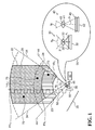
- Fig. 1 schematically shows a plan view of a TOF 3D imager 20 comprising a near TOF camera 30, a far TOF camera 40, and a light source 50. Details of the TOF cameras are shown in an inset 90.
- Near TOF camera 30 comprises an optical system represented by a lens 31 that collects light from objects imaged by the near TOF camera and images the collected light on a photosensor 32.
- Optical system 31 has an optical center 33 and a focal length f N that together with photosensor 32 define a wide-angle FOV for the near TOF camera that is characterized by relatively large, optionally fixed, horizontal view angle ⁇ N defined by lines 44.
- Numeral 44 designating the lines that define view angle ⁇ N of the wide angle FOV of near TOF camera 30 is also used to refer to the FOV, which may be referred to as "near FOV", of the near TOF camera 30.
- Optical system 31 also includes a shutter 35 for shuttering near TOF camera 30 open and closed.
- far TOF camera 40 comprises an optical system represented by a lens 41 that collects light from objects in the camera's FOV and images the collected light on a photosensor 42.
- the optical system has an optical center 43 and a focal length f F that together with photosensor 42 define a narrow-angle FOV for the far TOF camera that is characterized by relatively large, optionally fixed, horizontal view angle ⁇ F defined by lines 34.
- Numeral 34 designating the lines that define view angle ⁇ F of the wide angle FOV of far TOF camera 40 is also used to refer to the FOV, which may be referred to as "far FOV", of the far TOF camera.
- Optical system 41 also includes a shutter 45 for shuttering far TOF camera open and closed.
- Light source 50 is controllable by a controller 60 to radiate a train of light pulses to illuminate objects in near and far FOVs 44 and 34.
- Light pulses radiated by light source 50 are schematically represented by square “pulses” labeled with a numeral 52.
- light pulses 52 may comprise light provided by a suitable light emitting diode (LED) and/or laser from any portion of the spectrum, usually, light pulses 52 are near infrared (NIR) light pulses.
- LED light emitting diode
- NIR near infrared
- controller 60 controls near shutter 35 to shutter open near TOF camera 30 for a short exposure period having duration ⁇ N .
- ⁇ N the exposure period
- light reflected from the light pulse by features in near FOV 44 that reaches near TOF camera 30 is imaged by lens 31 onto photosensor 32.
- the imaged light is registered by the near TOF camera and is used to determine how long it takes light in light pulse 52 to travel round trip from light source 50 to the features and back to near TOF camera 30.
- the round trip time and the speed of light are used to determine how far the features are from the near TOF camera and therefore from TOF 3D imager 20.
- controller 60 controls shutter 45 in far TOF camera 40 to shutter open the far TOF camera for a short exposure period having duration ⁇ F following a delay ⁇ FD after each pulse 52 is radiated by light source 50.
- the far TOF camera images and registers light reflected from the light pulse that reaches the far TOF camera during the exposure period and uses the registered light to determine distances from TOF 3D imager 20 to features in far FOV 34.
- Far TOF camera 40 because of its narrow-angle FOV 34, images features farther from TOF 3D imager 20 with better spatial resolution than near TOF camera 30, but images a relatively small volume of space near to TOF 3D imager 20.
- near TOF camera 30, because of its relatively wide-angle FOV 44 is able to image a relatively large volume of space near to TOF 3D imager 20 and may be configured to image close features with acceptable spatial resolution.
- imaging range lower and upper bounds are established for near and far TOF cameras 30 and 40.
- the lower and upper range bounds associated with near TOF camera 30 be represented by NR L and NR U respectively.
- the lower and upper bounds for near TOF camera 30 are schematically shown in Fig. 1 by dashed lines that are labeled NR L and NR U .
- Let the lower and upper range bounds associated with far TOF camera 40 be represented by FR L and FR U respectively.
- the lower and upper bounds for far camera 40 are schematically shown in Fig. 1 by dashed lines that are labeled FR L and FR U .
- View angles ⁇ N and ⁇ F , and range bounds NR L , NR U , FR L , and FR U optionally define an active space schematically outlined by a bold dashed line 22 for TOF 3D imager 20.
- Numeral 22 that labels the dashed lines that outline the active space of TOF 3D imager 20 is also used to refer to the active space.
- view angle ⁇ N for wide-angle FOV 44 of near TOF camera 30 is determined so that active space 22 has an advantageous width close to TOF 3D imager 20.
- Near and far upper bounds NR U and FR U and view angle ⁇ F for narrow-angle FOV 34 of far TOF camera 40 are determined so that near and far TOF cameras 30 and 40 image objects at distances NR U and FR U respectively with substantially a same spatial resolution.
- Active space 22 therefore comprises three zones: a near zone 23, an intermediate zone 24 and a far zone 25.
- an active space for example for playing full-body 3D computer games active space 22 advantageously extends from NR L equal to about 0.80 m to FR U equal to about 3 m from TOF 3D imager 20. If at 0.80 m from the TOF 3D imager 20 active space 22 is about 1m wide, then advantageously, near TOF camera 30 has a view angle ⁇ N equal to about 62.5°.
- Controller 60 controls TOF 3D imager 20 and processes distance information provided by distance images acquired by near and far TOF cameras 30 and 40 responsive to the lower and upper bounds N RL , N RU , F RL , and F RU and zones 23, 24 and 25 that they define.
- controller 60 controls TOF 3D imager 20 using a delay ⁇ ND and duration of exposure period ⁇ N for near TOF camera 30 substantially equal respectively to delay ⁇ FD and exposure period ⁇ F for far TOF camera 40. Under these conditions of substantial equality, both TOF cameras acquire images for features in active space 22 over a same range of distances from the TOF 3D imager.
- controller 60 shutters far TOF camera 40 with ⁇ FD and ⁇ F determined so that far TOF camera 40 images a feature present in far FOV 34 with light from light source 50 only if the feature's distance from the near TOF camera is between FR L and FR U .
- controller shutters near TOF camera 30 with ⁇ ND and ⁇ F determined so that near TOF camera 30 images a feature present in near FOV 44 with light from light source 50 only if the feature's distance from the near TOF camera is between NR L and NR U .
- controller 60 may provide acceptable distance measurements for features in zone 23 using distance images provided only by near TOF camera 30.
- controller 60 may provide acceptable distance measurements for features in zone 25 using distance images provided only by far TOF camera 40.
- the controller optionally uses data provided by both near and far TOF cameras.
- Solid circles 73, 74 and 75 schematically represent by features at locations in zones 23, 24 and 25
- controller designates one of the TOF cameras as a "prime" TOF camera.
- the letter “C” represents the prime camera.
- the letter C* represents the other camera, which may be referred to as a "secondary" camera. It is assumed that distance from TOF 3D imager 20 is to be determined for a feature imaged on a pixel P j of the prime camera C.
- the prime camera is assumed to be near TOF camera 30, and the feature imaged on pixel P j is assumed to be feature 74 shown in Fig. 1 located in intermediate zone 24.
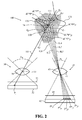
- Fig. 2 schematically shows a greatly enlarged view of near and far TOF cameras 30 and 40, a region 100 of intermediate zone 24 in which feature 74 is located and pixel P j on which feature 74 is imaged on photosensor 32 of prime camera C, near TOF camera 30.
- feature 74 is assumed to be constrained to lie along a line in space, an imaging line 101, also referred to as a prime imaging line 101, that passes from the feature through optical center 33 of near TOF camera 30 and intersect pixel P j .
- a trial distance for feature 74 is a distance "dCP j " determined from the distance image of feature 74 acquired by pixel P j .
- a distance "d" along prime imaging line 101 is assumed to be an actual distance along the imaging line at which feature 74 is located with a probability given by a probability distribution function P (d;dCP j , ⁇ j ), where ⁇ j is a measure of an error associated with trial distance dCP j .
- Shot and read noise typically generate an error associated with a trial distance.
- a segment of imaging line 101 between witness lines 110 and 111 schematically represents a magnitude of an error associated with dCP j .
- probability distribution P (d;dCP j , ⁇ j ) is assumed to be a normal distribution represented by a curve 120 shown along imaging line 101 having a maximum at distance dCP j and a standard deviation ⁇ j .
- a pixel P* jm in photosensor 42 of far TOF camera 40 is determined on which region R jm would be imaged, were it located in the region.
- Fig. 2 M is arbitrarily shown equal to five.
- Regions R jm are schematically indicated along the segment of prime imaging line 101 between witness lines 110 and 111 by diamond icons labeled by corresponding distances d j1 , d j2 , ... d j5 . corresponding respectively to R j1 , R j2 , ... R j5 .
- Pixel P* jm lies at an end of an imaging line IL m , hereinafter also referred to as a secondary imaging line IL m that extends from d jm through optical center 43 of secondary camera, far TOF camera 40.
- a distance image acquired by pixel P* jm provides a distance dC*P* jm along its associated imaging line IL m for a feature imaged on the pixel, and that the distance dC*P* jm is associated with an error ⁇ * jm .
- Distances dC*P* jm are graphically represented by circle icons labeled by distances dC*P* jm , (1 ⁇ m ⁇ 5) along secondary imaging lines IL m .
- a probability that a distance d* m along imaging line IL m for the feature imaged on pixel P* jm is the actual distance for the feature be given by a probability distribution function P(d* m ; dC*P* jm , ⁇ * jm ).
- a probability that the d* jm is the actual distance of the feature imaged on pixel P* jm from far camera 40 is P(d* jm ; dC*P* jm , ⁇ * jm ).
- controller 60 determines that a distance DCP j for the feature, for example feature 74, imaged on pixel P j of prime, near TOF camera 30, is a distance d m (1 ⁇ m ⁇ M) that maximizes: P (d m ;dCP j , ⁇ j )• P (d* jm ;dC*P* jm , ⁇ * jm ).
- near TOF camera 30 is designated the prime camera and far TOF camera 40 the secondary camera
- the procedure for determining distance is generally substantially independent of which camera is the prime camera.
- the roles of the cameras may be reversed, with far TOF camera 40 designated the prime camera and near TOF camera the secondary camera and prime imaging line 101 associated with the far TOF camera.
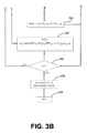
- Figs. 3A and 3B show a flow diagram 200 of an algorithm, also referred to by the numeral 200, by which TOF 3D imager 20 processes information from images of active space 22 acquired by near and far TOF cameras 30 and 40 to determine distances to features in active space 22 and provide a range image for features in the active space.
- controller 60 determines whether to adjust TOF 3D imager 20 to operate in a zoom-out mode or in a zoom-in mode. Adjusting the TOF 3D imager comprises determining which camera, near TOF camera 30, (the wide-angle FOV, zoom-out camera) or far TOF camera 40 (the narrow-angle FOV, zoom-in camera), is designated the prime camera for processing distance information provided by the cameras.
- the discussion above with respect to Fig. 1 provides an example of a role of a prime camera in determining distances to features in active space 22 ( Fig. 1 ).
- controller 60 estimates from distances provided by near and far TOF cameras 30 and 40 a number of features of interest present in each of near, overlap and far zones zones 23, 24, and 25 in active space 22.
- the controller determines zoom-in or zoom-out in response to the estimated numbers of features.
- controller 60 adjusts TOF 3D imager 20 to operate in a zoom-in mode with near TOF camera 30 the prime camera, or zoom-out mode with far TOF camera 40 the prime camera, respectively.
- controller 60 leaves the TOF 3D imager operating in a zoom mode in which it was operating prior to estimating the number of features of interest or determines the zoom mode in accordance with a predetermined default procedure.
- controller 60 sets intensity of light pulses radiated by light source 50 to match the choice of zoom-mode. If the zoom mode is zoom-out, the controller optionally sets the intensity to a moderate level to reduce the probability that features in near zone 23 close to TOF 3D imager 20 may reflect amounts of light from the light pulses back to near and far TOF cameras 30 and 40 that saturates pixels in the TOF cameras. If the zoom mode is zoom-in, controller 60 optionally sets the intensity of radiated pulses greater than the moderate intensity chosen for the zoom-out mode to reduce a probability that features in far zone 25, relatively far from TOF 3D imager 20, do not reflect sufficient light back to the TOF cameras for acceptable imaging. An intermediate intensity is optionally determined for a situation where a relatively large number of features of interest are found in intermediate zone 24.
- the controller initializes to zero an index "j" that designates pixels in prime camera C, which may be either near TOF camera 30 or far TOF camera 40.
- Index j has a maximum value equal to J, which represents a total number of pixels in near TOF camera 30.
- the controller increases the index by one.
- controller 60 determines a trial distance dCP j from a distance image acquired by pixel P j in prime camera C for a feature in active space 22.
- the controller optionally determines in a decision block 216 whether the trial distance dCP j indicates if the feature imaged on pixel P j appears to be located in intermediate zone 24. If it is, optionally in a block 218, controller 60 uses distance information from both prime camera C and secondary camera C* to determine a distance DCP j for the feature imaged on P j .
- the controller determines from the geometry of near and far TOF cameras 30 and 40 and their positions relative to each other in TOF 3D imager 20, which pixel P* k:j ⁇ k corresponds to pixel P j , and images substantially a same feature that pixel P j images.
- the weighting factors may for example weigh information from the prime camera C more than information from the secondary camera C*, or weigh the trial distances by a function of their respective errors.
- controller 60 optionally continues from block 218 to block 208 via a decision block 224 to increase index j or to block 226 to provide a range image for active space 22 and proceed to block 228 to end the process.
- controller 60 finds that trial distance dCP j does not indicate that the feature is located in intermediate zone 24 then either the trial distance indicates that the feature is located in C*-zone, the zone in active space 22 associated with secondary camera C*, or the trial distance is invalid and the controller proceeds optionally to a block 220.
- controller optionally proceeds to block 224 and thereafter to return to block 208 to repeat the procedure for a next pixel in prime camera C, or to block 226 to provide a range image and then end the procedure.
- controller may proceed to repeatedly execute algorithm 200 for each set of images acquired for the active space during the game.
- each of the verbs, "comprise” “include” and “have”, and conjugates thereof, are used to indicate that the object or objects of the verb are not necessarily a complete listing of components, elements or parts of the subject or subjects of the verb.
Description
- As an object moves farther from a camera, an angle that the object subtends at a photosensor on which the camera images the object decreases, and a size of an image of the object that the camera projects onto the photosensor and a number of pixels in the photosensor covered by the image decreases. With the decrease in image size and number of pixels onto which the image is projected, resolution of the object's features decreases and details of the object may become indiscernible. An optical system of a camera that provides zoom functionality is adjustable so that as an object recedes from the camera it may be "zoomed in" to conserve or increase an angle that the object subtends at the camera photosensor. Zooming in on an object magnifies an image of the object that the camera focuses onto its photosensor and improves resolution of imaged features of the object.
- Zoom adjustment for a camera is typically provided by a mechanical system that moves a lens or lenses in the camera's optical system to change the relative positions of the lenses and thereby a focal length of the optical system. The system moves the lenses to provide the camera with a relatively long focal length and a field of view (FOV) characterized by a relatively small view angle to zoom in on an object and magnify an image of the object that the camera acquires. The system moves the lenses to provide the camera with a relatively short focal length and relatively wide-angle FOV to "zoom out" the object, and demagnify the object's image that the camera acquires.
- The FOV of a camera is a region of space defined by a solid angle that extends from an optical center of the camera and for which points therein are imaged by the camera's optical system on the camera photosensor. Size of a FOV for most imaging purposes is conveniently measured by horizontal and vertical view angles. The horizontal and vertical view angles are largest angles between two lines that extend from the optical center of the camera, are contained in the FOV, and are coplanar with the camera optical axis in a plane respectively parallel and perpendicular to the ground.
- Whereas zooming in magnifies images of objects in a scene that the camera images, it also decreases the view angles of the camera's FOV and as a result decreases a size of the imaged scene, and a portion of an environment surrounding the camera that the camera is able to image. Whereas zooming out demagnifies images of objects in a scene that the camera images, it also increases the view angles of the camera's FOV and as a result increases a size of the imaged scene and a portion of an environment surrounding the camera that the camera is able to image.
- For many applications, such as for tracking a person's gestures to interface the person with a computer, it is advantageous that a camera that images the person image the person with an acceptable degree of resolution over a relatively large volume of space, hereinafter referred to as an "active space". For example, to interface a person with a computer game, hereinafter also a full-body, three-dimensional (3D) game, such as a boxing game or a game requiring exercise, that responds to full body motion of the person, it can be advantageous that the camera image the person with acceptable resolution substantially everywhere in the active space. The active space may for example have a "length" that extends from a distance near the camera equal to about 1 m (meters) to a far distance from the camera equal to about 3 m. To provide advantageous image resolution over the length of the active space, the camera optics may be configured for zoom adjustment.
- Imaging a person to track the person's gestures or motion during playing a 3D game is advantageously performed using a 3D camera, such as a triangulation or a time of flight (TOF) 3D camera, which acquires distances to features of the person and optionally features of the person's environment. The distances acquired by the 3D camera for the person and optionally the person's environment at a substantially same given time provides a "range image" of a scene comprising the person. 3D cameras are generally active illumination cameras that image a scene with light they generate and configure to determine distances to features in the scene.
- A triangulation type 3D camera acquires distances to features in a scene from angles at which the camera images the features from two, generally slightly, different perspectives. The triangulation camera may illuminate the scene with spatially modulated light referred to as "structured light". A time of flight (TOF) 3D camera acquires distances to features in a scene that the camera images by timing how long it takes temporally modulated light that it transmits to travel to the features and back to the camera. The camera transmits the light generally in very short light pulses and images light from the pulses that are reflected by the features that it collects to determine round trip, that is "back and forth", travel times for light.
- Providing a 3D camera with zoom optics is generally both technically and cost-wise challenging.
-
DE 10 2009 045600 A1 describes a 3D camera having a pixel array on the basis of a mixing detection, implemented such that individual pixels of the pixel array can be merged to form pixel blocks. -
DE 10 2009 046108 A1 describes a camera system having at least two TOF receivers and an active lighting system, in which the two TOF receivers are arranged offset with respect to one another in order to bring about a stereo effect. -
US 2008/0273758 A1 describes that an apparatus for monitoring a spatial area, in particular for safeguarding a hazardous area of an automatically operated installation, comprises an illumination device which at least temporarily emits light signals into the spatial area. A first image recording unit records a first image of the spatial area. The first image recording unit comprises an image sensor having a plurality of pixels. An evaluation unit determines a distance value for at least one spatial area point, which is located in the spatial area and is imaged on at least one pixel, by means of a propagation type measurement. The propagation type measurement suffers from a limited unambiguity range. Therefore, a test device is designed to check the distance value by means of a reference distance value determined from a second image of said spatial area. - An embodiment of the invention relates to providing a 3D imaging system, hereinafter also referred to as a "3D imager", comprising a first 3D camera having a wide-angle FOV that overlaps at least a portion of a narrow-angle FOV of a second 3D camera. The FOVs of the first and second 3D cameras define an active space of the 3D imager. The 3D imager comprises a processor programmed with an executable instruction set for implementing an algorithm that provides a range image of features in the active space responsive to distance information provided by the first and second 3D cameras.
- In accordance with an embodiment of the invention, the algorithm determines distances to features in a first "near region" of the active space relatively near to the 3D imager responsive to distances determined by the first 3D camera, hereinafter also referred to as a "near camera". The algorithm determines distances to features in a second "far region" of the active space relatively far from the 3D imager responsive to distances determined by the second 3D camera, hereinafter also referred to as a "far camera". Distances to features in a third, "overlap" region of the active space where the FOVs of the near and far 3D cameras overlap are determined using distance information provided by both 3D cameras.
- In an embodiment of the invention, the near and far 3D cameras comprise near and far TOF 3D cameras respectively, hereinafter also referred to as near and far TOF cameras. A pixel in the near or far TOF camera acquires an image, hereinafter also a "distance image", that provides a measure of distance from the TOF camera of a feature in the active space that is imaged on the pixel. In accordance with an embodiment of the invention, the algorithm provides a method of correlating pixels in the TOF cameras to determine which pixels in the near or far TOF camera image a substantially same feature of the active space that is imaged by pixels in the far or near TOF camera respectively. The correlation is performed responsive to distance information that distance images acquired by the pixels provide. Optionally, the correlation is performed by maximizing a probability distribution that the pixels in the different TOF cameras image a same feature in the active space.
- In an embodiment, the 3D imager comprises a controller that controls intensity of light provided by the 3D imager to illuminate the active space responsive to distance of features in the active space that are imaged by the 3D imager.
- By configuring a 3D imager in accordance with an embodiment of the invention, so that it comprises near and far TOF cameras having respectively wide-angle and narrow-angle FOVs, the 3D imager has a relatively large active space. The 3D imager images features substantially anywhere in the space at a same relatively high spatial resolution without having to use conventional zoom optics.
- In the discussion, unless otherwise stated, adjectives such as "substantially" and "about" modifying a condition or relationship characteristic of a feature or features of an embodiment of the invention, are understood to mean that the condition or characteristic is defined to within tolerances that are acceptable for operation of the embodiment for an application for which it is intended.
- This Summary is provided to introduce a selection of concepts in a simplified form that are further described below in the Detailed Description. This Summary is not intended to identify key features or essential features of the claimed subject matter, nor is it intended to be used to limit the scope of the claimed subject matter.
- Non-limiting examples of embodiments of the invention are described below with reference to figures attached hereto that are listed following this paragraph. Identical structures, elements or parts that appear in more than one figure are generally labeled with a same numeral in all the figures in which they appear. Dimensions of components and features shown in the figures are chosen for convenience and clarity of presentation and are not necessarily shown to scale
-
Fig. 1 schematically shows a plan view of a 3D imager comprising first and second TOF cameras and an active space of the imager provided by the FOVs of the TOF cameras, in accordance with an embodiment of the invention; -
Fig. 2 schematically shows geometric relationships between distance images of features in a same region of the active space of the 3D imager show inFig. 1 that are acquired by the TOF cameras and used to determine a distance to a feature in the active space, in accordance with an embodiment of the invention; and -
Figs. 3A and3B show a flow diagram of an algorithm for determining distance to a feature in the active space, in accordance with an embodiment of the invention. - In the following text of the detailed description, aspects of a TOF 3D imager comprising a plurality of optionally two TOF cameras are discussed with reference to
Fig. 1 , which shows components of the TOF 3D imager and an active space provided by the FOVs of the TOF cameras.Fig. 2 schematically shows geometrical relationships between distance images acquired by pixels in the two TOF cameras for features in a same region of the active space of the TOF 3D imager shown inFig. 1 . The figure schematically shows uncertainties in distance measurements provided by the distance images and frequency distributions of the distance measurements provided by pixels in the TOF cameras that are assumed for convenience to be Gaussian. A method for determining distances to features in the active space using information provided by the two TOF cameras and for correlating pixels to determine which pixels in the two cameras correspond and image substantially same features in the active space are discussed with reference toFig. 2 and to the flow diagram shown inFigs. 3A and3B . -
Fig. 1 schematically shows a plan view of aTOF 3D imager 20 comprising anear TOF camera 30, a farTOF camera 40, and alight source 50. Details of the TOF cameras are shown in aninset 90. - Near
TOF camera 30 comprises an optical system represented by alens 31 that collects light from objects imaged by the near TOF camera and images the collected light on aphotosensor 32.Optical system 31 has anoptical center 33 and a focal length fN that together withphotosensor 32 define a wide-angle FOV for the near TOF camera that is characterized by relatively large, optionally fixed, horizontal view angle θN defined bylines 44.Numeral 44 designating the lines that define view angle θN of the wide angle FOV ofnear TOF camera 30 is also used to refer to the FOV, which may be referred to as "near FOV", of thenear TOF camera 30.Optical system 31 also includes ashutter 35 for shuttering nearTOF camera 30 open and closed. - Similarly, far
TOF camera 40 comprises an optical system represented by alens 41 that collects light from objects in the camera's FOV and images the collected light on aphotosensor 42. The optical system has anoptical center 43 and a focal length fF that together withphotosensor 42 define a narrow-angle FOV for the far TOF camera that is characterized by relatively large, optionally fixed, horizontal view angle θF defined bylines 34.Numeral 34 designating the lines that define view angle θF of the wide angle FOV of farTOF camera 40 is also used to refer to the FOV, which may be referred to as "far FOV", of the far TOF camera.Optical system 41 also includes ashutter 45 for shuttering far TOF camera open and closed. -
Light source 50 is controllable by acontroller 60 to radiate a train of light pulses to illuminate objects in near and far FOVs 44 and 34. Light pulses radiated bylight source 50 are schematically represented by square "pulses" labeled with a numeral 52. Whereaslight pulses 52 may comprise light provided by a suitable light emitting diode (LED) and/or laser from any portion of the spectrum, usually,light pulses 52 are near infrared (NIR) light pulses. - Following a predetermined delay, τND, from a time at which each
light pulse 52 in the train of light pulses is radiated bylight source 50 to illuminate objects in near and far FOVs 44 and 34,controller 60 controls nearshutter 35 to shutter open nearTOF camera 30 for a short exposure period having duration τN. During the exposure period, light reflected from the light pulse by features innear FOV 44 that reaches nearTOF camera 30 is imaged bylens 31 ontophotosensor 32. The imaged light is registered by the near TOF camera and is used to determine how long it takes light inlight pulse 52 to travel round trip fromlight source 50 to the features and back to nearTOF camera 30. The round trip time and the speed of light are used to determine how far the features are from the near TOF camera and therefore fromTOF 3D imager 20. - Similarly,
controller 60 controls shutter 45 in farTOF camera 40 to shutter open the far TOF camera for a short exposure period having duration τF following a delay τFD after eachpulse 52 is radiated bylight source 50. The far TOF camera images and registers light reflected from the light pulse that reaches the far TOF camera during the exposure period and uses the registered light to determine distances fromTOF 3D imager 20 to features in farFOV 34. -
Far TOF camera 40, because of its narrow-angle FOV 34, images features farther fromTOF 3D imager 20 with better spatial resolution than nearTOF camera 30, but images a relatively small volume of space near toTOF 3D imager 20. On the other hand, nearTOF camera 30, because of its relatively wide-angle FOV 44 is able to image a relatively large volume of space near toTOF 3D imager 20 and may be configured to image close features with acceptable spatial resolution. - In accordance with an embodiment of the invention, to combine near and far FOVs 44 and 34 to provide an advantageous active space for
TOF 3D imager 20, and to determine how to use distance information provided by near andfar TOF cameras far TOF cameras near TOF camera 30 be represented by NRL and NRU respectively. The lower and upper bounds fornear TOF camera 30 are schematically shown inFig. 1 by dashed lines that are labeled NRL and NRU. Let the lower and upper range bounds associated with farTOF camera 40 be represented by FRL and FRU respectively. The lower and upper bounds forfar camera 40 are schematically shown inFig. 1 by dashed lines that are labeled FRL and FRU. - View angles θN and θF, and range bounds NRL, NRU, FRL, and FRU optionally define an active space schematically outlined by a bold dashed
line 22 forTOF 3D imager 20.Numeral 22 that labels the dashed lines that outline the active space ofTOF 3D imager 20 is also used to refer to the active space. - In an embodiment of the invention, view angle θN for wide-
angle FOV 44 ofnear TOF camera 30 is determined so thatactive space 22 has an advantageous width close toTOF 3D imager 20. Near and far upper bounds NRU and FRU and view angle θF for narrow-angle FOV 34 of farTOF camera 40 are determined so that near andfar TOF cameras photosensors far TOF cameras - By way of a numerical example, assume that near and
far TOF cameras far TOF cameras distances 200 cm and 300 cm respectively if their FOV angles θN and θF are respectively equal to about 74° and about 53°. - To provide a smoothly continuous
active space 22 and to facilitate spatial registration of images provided by near andfar TOF cameras TOF camera 40 and upper bound range NRU fornear TOF camera 30 are determined so that FRL < NRU.Active space 22 therefore comprises three zones: anear zone 23, anintermediate zone 24 and afar zone 25. - By way of a numerical example assume that an active space, for example for playing full-body 3D computer games
active space 22 advantageously extends from NRL equal to about 0.80 m to FRU equal to about 3 m fromTOF 3D imager 20. If at 0.80 m from theTOF 3D imager 20active space 22 is about 1m wide, then advantageously, nearTOF camera 30 has a view angle θN equal to about 62.5°. If at a distance NRU fromTOF 3D imager 20active space 22 advantageously has a width of about 2.5 m then NRU is equal to about 2 m and θF = arctan[θF/2] = arctan((NRU/FRU)tan[θN/2]θF) is equal to about 42°. If the near and far TOF cameras have square pixels that are 15 µm on a side and are advantageously able to resolve features separated by about 1 cm at distances NRU and FRU then their focal lengths fN and fF are advantageously equal to about 30 mm (millimeters) and 45 mm respectively. -
Controller 60 controls TOF3D imager 20 and processes distance information provided by distance images acquired by near andfar TOF cameras zones controller 60 controls TOF3D imager 20 using a delay τND and duration of exposure period τN fornear TOF camera 30 substantially equal respectively to delay τFD and exposure period τF for farTOF camera 40. Under these conditions of substantial equality, both TOF cameras acquire images for features inactive space 22 over a same range of distances from the TOF 3D imager. - In an embodiment of the invention,
controller 60 shutters farTOF camera 40 with τFD and τF determined so that farTOF camera 40 images a feature present in farFOV 34 with light fromlight source 50 only if the feature's distance from the near TOF camera is between FRL and FRU. Similarly, the controller shutters nearTOF camera 30 with τND and τF determined so that nearTOF camera 30 images a feature present innear FOV 44 with light fromlight source 50 only if the feature's distance from the near TOF camera is between NRL and NRU. - Generally,
controller 60 may provide acceptable distance measurements for features inzone 23 using distance images provided only bynear TOF camera 30. Generally,controller 60 may provide acceptable distance measurements for features inzone 25 using distance images provided only by farTOF camera 40. For features that are located inintermediate zone 24 or for an apparently invalid or indeterminate distance provided by one of the TOF cameras, the controller optionally uses data provided by both near and far TOF cameras.Solid circles zones - For a distance to a feature that is determined from distance images from both near and
far TOF cameras TOF 3D imager 20 is to be determined for a feature imaged on a pixel Pj of the prime camera C. By way of example, in the following discussion referencingFig. 2 , the prime camera is assumed to be nearTOF camera 30, and the feature imaged on pixel Pj is assumed to befeature 74 shown inFig. 1 located inintermediate zone 24. -
Fig. 2 schematically shows a greatly enlarged view of near andfar TOF cameras region 100 ofintermediate zone 24 in which feature 74 is located and pixel Pj on which feature 74 is imaged onphotosensor 32 of prime camera C, nearTOF camera 30. - In accordance with an embodiment of the invention, feature 74 is assumed to be constrained to lie along a line in space, an
imaging line 101, also referred to as aprime imaging line 101, that passes from the feature throughoptical center 33 ofnear TOF camera 30 and intersect pixel Pj. A trial distance forfeature 74 is a distance "dCPj" determined from
the distance image offeature 74 acquired by pixel Pj. A distance "d" alongprime imaging line 101 is assumed to be an actual distance along the imaging line at which feature 74 is located with a probability given by a probability distribution function P (d;dCPj,σj), where σj is a measure of an error associated with trial distance dCPj. Shot and read noise typically generate an error associated with a trial distance. A segment ofimaging line 101 between
witness lines Fig. 2 , probability distribution P (d;dCPj,σj) is assumed to be a normal distribution represented by acurve 120 shown alongimaging line 101 having a maximum at distance dCPj and a standard deviation σj. - In accordance with an embodiment of the invention, for each of a plurality of M regions Rjm, (1 ≤ m ≤ M), along
imaging line 101, at distances djm betweenwitness lines photosensor 42 of farTOF camera 40 is determined on which region Rjm would be imaged, were it located in the region. InFig. 2 M is arbitrarily shown equal to five. Regions Rjm are schematically indicated along the segment ofprime imaging line 101 betweenwitness lines - Pixel P*jm lies at an end of an imaging line ILm, hereinafter also referred to as a secondary imaging line ILm that extends from djm through
optical center 43 of secondary camera, farTOF camera 40. Assume that a distance image acquired by pixel P*jm provides a distance dC*P*jm along its associated imaging line ILm for a feature imaged on the pixel, and that the distance dC*P*jm is associated with an error σ*jm. Distances dC*P*jm are graphically represented by circle icons labeled by distances dC*P*jm, (1 ≤ m ≤ 5) along secondary imaging lines ILm. - Let a probability that a distance d*m along imaging line ILm for the feature imaged on pixel P*jm is the actual distance for the feature be given by a probability distribution function P(d*m; dC*P*jm, σ*jm). In
Fig. 2 an exemplary distribution P (d*jm; dC*P*jm, σ*jm) is shown as anormal distribution 130 for m = 5. If the intersection ofprime imaging line 101 with secondary imaging line ILm is located at a distance d*jm along imaging line ILm from farTOF camera 40, a probability that the d*jm is the actual distance of the feature imaged on pixel P*jm fromfar camera 40 is P(d*jm; dC*P*jm, σ*jm). - In accordance with an embodiment of the invention,
controller 60 determines that a distance DCPj for the feature, forexample feature 74, imaged on pixel Pj of prime, nearTOF camera 30, is a distance dm (1 ≤ m ≤ M) that maximizes:
P (dm;dCPj,σj)•P(d*jm;dC*P*jm,σ*jm).
- It is noted that whereas in the discussion above, near
TOF camera 30 is designated the prime camera andfar TOF camera 40 the secondary camera, the procedure for determining distance is generally substantially independent of which camera is the prime camera. The roles of the cameras may be reversed, with farTOF camera 40 designated the prime camera and near TOF camera the secondary camera andprime imaging line 101 associated with the far TOF camera. -
Figs. 3A and3B show a flow diagram 200 of an algorithm, also referred to by the numeral 200, by whichTOF 3D imager 20 processes information from images ofactive space 22 acquired by near andfar TOF cameras active space 22 and provide a range image for features in the active space. - In a
block 202,optionally controller 60 determines whether to adjustTOF 3D imager 20 to operate in a zoom-out mode or in a zoom-in mode. Adjusting the TOF 3D imager comprises determining which camera, nearTOF camera 30, (the wide-angle FOV, zoom-out camera) or far TOF camera 40 (the narrow-angle FOV, zoom-in camera), is designated the prime camera for processing distance information provided by the cameras. The discussion above with respect toFig. 1 provides an example of a role of a prime camera in determining distances to features in active space 22 (Fig. 1 ). Optionally, to determine which camera is advantageously designated the prime camera,controller 60 estimates from distances provided by near andfar TOF cameras 30 and 40 a number of features of interest present in each of near, overlap andfar zones zones active space 22. The controller determines zoom-in or zoom-out in response to the estimated numbers of features. - For example, if there is a preponderance of features in the near or
far zones controller 60 adjusts TOF3D imager 20 to operate in a zoom-in mode withnear TOF camera 30 the prime camera, or zoom-out mode with farTOF camera 40 the prime camera, respectively. Optionally, if a preponderance of features of interest is found present in the intermediate zone,controller 60 leaves the TOF 3D imager operating in a zoom mode in which it was operating prior to estimating the number of features of interest or determines the zoom mode in accordance with a predetermined default procedure. - In a
block 204controller 60 sets intensity of light pulses radiated bylight source 50 to match the choice of zoom-mode. If the zoom mode is zoom-out, the controller optionally sets the intensity to a moderate level to reduce the probability that features in nearzone 23 close toTOF 3D imager 20 may reflect amounts of light from the light pulses back to near andfar TOF cameras controller 60 optionally sets the intensity of radiated pulses greater than the moderate intensity chosen for the zoom-out mode to reduce a probability that features infar zone 25, relatively far fromTOF 3D imager 20, do not reflect sufficient light back to the TOF cameras for acceptable imaging. An intermediate intensity is optionally determined for a situation where a relatively large number of features of interest are found inintermediate zone 24. - In a
block 206 the controller initializes to zero an index "j" that designates pixels in prime camera C, which may be either nearTOF camera 30 or farTOF camera 40. Index j has a maximum value equal to J, which represents a total number of pixels innear TOF camera 30. In ablock 208, the controller increases the index by one. In ablock 210,controller 60 determines a trial distance dCPj from a distance image acquired by pixel Pj in
prime camera C for a feature inactive space 22. In adecision block 212,controller 60 determines if the value for dCPj indicates whether the feature imaged on pixel Pj is located in the zone, hereinafter also referred to as a "C-zone", inactive space 22 that is associated with prime camera C. That is, if nearTOF camera 30 is the prime camera C, the C-zone is near zone 23 (Fig. 1 ), and if farTOF camera 40 is the prime camera C, the C-zone isfar zone 25. If the imaged features appears to be in the C-zone, in ablock 214 the controller determines that, optionally, a distance DCPj = dCPj is the distance for the feature imaged on pixel Pj of the prime camera C. - The controller then, optionally, proceeds to a
block 224 and determines if j =J, the total number of pixels in prime camera C. If j is not equal to J,controller 60 returns to block 208 to increase index j by one and proceed to determine a distance for a feature imaged on a next pixel P(j+1). If j =J,controller 60 ends the process for determining distances for the pixels Pj in prime camera C, and optionally in ablock 226 it uses the distances DCPj j=1→J to provide a range image foractive space 22. The controller then optionally proceeds to a block 228 to end the process. - In an embodiment of the invention, if the feature is not in the C-zone, the controller optionally determines in a
decision block 216 whether the trial distance dCPj indicates if the feature imaged on pixel Pj appears to be located inintermediate zone 24. If it is, optionally in ablock 218,controller 60 uses distance information from both prime camera C and secondary camera C* to determine a distance DCPj for the feature imaged on Pj. Optionally, the controller determines from the geometry of near andfar TOF cameras TOF 3D imager 20, which pixel P*k:j→k corresponds to pixel Pj, and images substantially a same feature that pixel Pj images. Optionally, the controller determines the distance DCPj as a weighted average of the trial distance dCPj and the trial distance dCP*k:j→k provided by the distance image acquired by pixel P*k:j→k in accordance with an equation DCPj = wCdCPj+wC*dC*P*k:j→k, where wC and wC* are weighting factors. The weighting factors may for example weigh information from the prime camera C more than information from the secondary camera C*, or weigh the trial distances by a function of their respective errors. After determining DCPj,controller 60 optionally continues fromblock 218 to block 208 via adecision block 224 to increase index j or to block 226 to provide a range image foractive space 22 and proceed to block 228 to end the process. - If in
block 216controller 60 finds that trial distance dCPj does not indicate that the feature is located inintermediate zone 24 then either the trial distance indicates that the feature is located in C*-zone, the zone inactive space 22 associated with secondary camera C*, or the trial distance is invalid and the controller proceeds optionally to ablock 220. Optionally, the controller executes a procedure similar to that described above with reference toFig. 2 and determines DCPj in accordance with an expression DCPj = {dm| MAX[P (dm;dCPj,σj)·P(d*jm;dC*P*jm,σ*jm)]}. - From
block 220 the controller optionally proceeds to block 224 and thereafter to return to block 208 to repeat the procedure for a next pixel in prime camera C, or to block 226 to provide a range image and then end the procedure. - If of course TOF
3D imager 20 is in continuous operation, for example in support of a full body 3D computer game, to repeatedly image features inactive space 22, controller may proceed to repeatedly executealgorithm 200 for each set of images acquired for the active space during the game. - In the description and claims of the present application, each of the verbs, "comprise" "include" and "have", and conjugates thereof, are used to indicate that the object or objects of the verb are not necessarily a complete listing of components, elements or parts of the subject or subjects of the verb.
- Descriptions of embodiments of the invention in the present application are provided by way of example and are not intended to limit the scope of the invention. The described embodiments comprise different features, not all of which are required in all embodiments of the invention. Some embodiments utilize only some of the features or possible combinations of the features. Variations of embodiments of the invention that are described, and embodiments of the invention comprising different combinations of features noted in the described embodiments, will occur to persons of the art. The scope of the invention is limited only by the claims.
Claims (7)
- A three-dimensional imaging system that images features in an active space and determines distances to the features, the imaging system comprising:a light source (50) that illuminates the active space with at least one light pulse;first and second time-of-flight cameras (30, 40) comprising first
and second photosensors (32, 42) respectively having optical centers and pixels on which the cameras image light reflected from the at least one light pulse to acquire distance images of the features, wherein the first and second time-of-flight cameras have wide-angle and narrow-angle fields of view respectively, which overlap to provide the active space;a plurality of range bounds (NRL, NRU, FRL, FRU) that divide the active space into zones; anda controller (60) that processes the distance images responsive to the zones to determine distances to the features,wherein the range bounds comprise a near range lower bound, NRL, a near range upper bound NRU, a far range lower bound FRL, and a far range upper bound, FRU,
wherein the range bounds satisfy a relationship NRL < FRL < NRU < FRU and divide the active space into near, intermediate, and far zones, for which distances to features in the active space lie between NRL and FRL, between FRL and NRU, and between NRU and FRU, respectively,
wherein to provide a range image comprising distances to features in the active space, the controller (60):designates one of the time-of-flight cameras (30, 40) a
prime camera and the other a secondary camera;determines for each of a plurality of pixels in the prime camera a trial distance for a feature in the active space that is imaged on the pixel;determines the distance to the feature to be the trial distance if the prime camera is the first camera and the determined distance is in the near zone or the prime camera is the second camera and the trial distance is in the far zone;determines the distance responsive to the trial distance and a distance provided by a pixel in the secondary camera if the prime camera is the first camera and the determined distance is not in the near zone or the prime camera is the second camera and the trial distance is not in the far zone; anduses the distances determined for the pixels in the prime camera for the distances in the range image. - Apparatus according to claim 1 wherein the trial distance lies in the intermediate zone.
- Apparatus according to claim 2 wherein the controller (60) determines the distance to the feature as an average of the trial distance and the distance provided by the pixel in the secondary camera (30/40).
- Apparatus according to claim 1 wherein the prime camera (30/40) is the first camera and the trial distance lies in the far zone or the prime camera is the second camera and the trial distance lies in the near zone.
- Apparatus according to claim 4 wherein the controller (60) determines which pixels in the secondary camera image points along a line that passes through the pixel in the prime camera (30/40) and the optical center of the prime camera.
- Apparatus according to claim 5, wherein the controller (60) determines a distance for each of the determined pixels in the secondary camera (30/40) responsive to a distance image acquired by the pixel with light from the at least one light pulse.
- Apparatus according to claim 6 wherein the controller (60):determines a probability distribution that a given distance along a line that passes through the optical center of the secondary camera (30/40) and the determined pixel is an actual distance of the feature imaged on the determined pixel from the secondary camera;determines the probability distribution that a given distance along the line in the prime camera (30/40) is an actual distance of the feature imaged on the prime camera pixel from the prime camera; anduses the probability distributions to determine a distance of the feature imaged on the prime camera pixel from the prime camera.
Applications Claiming Priority (2)
| Application Number | Priority Date | Filing Date | Title |
|---|---|---|---|
| US13/356,618 US9720089B2 (en) | 2012-01-23 | 2012-01-23 | 3D zoom imager |
| PCT/US2013/020693 WO2013112284A1 (en) | 2012-01-23 | 2013-01-08 | 3d zoom imager |
Publications (3)
| Publication Number | Publication Date |
|---|---|
| EP2807826A1 EP2807826A1 (en) | 2014-12-03 |
| EP2807826A4 EP2807826A4 (en) | 2015-06-03 |
| EP2807826B1 true EP2807826B1 (en) | 2016-11-30 |
Family
ID=48796901
Family Applications (1)
| Application Number | Title | Priority Date | Filing Date |
|---|---|---|---|
| EP13740760.7A Active EP2807826B1 (en) | 2012-01-23 | 2013-01-08 | 3d zoom imager |
Country Status (6)
| Country | Link |
|---|---|
| US (1) | US9720089B2 (en) |
| EP (1) | EP2807826B1 (en) |
| JP (1) | JP2015510586A (en) |
| KR (1) | KR101992511B1 (en) |
| CN (1) | CN104094594B (en) |
| WO (1) | WO2013112284A1 (en) |
Families Citing this family (34)
| Publication number | Priority date | Publication date | Assignee | Title |
|---|---|---|---|---|
| US8988508B2 (en) * | 2010-09-24 | 2015-03-24 | Microsoft Technology Licensing, Llc. | Wide angle field of view active illumination imaging system |
| US10154177B2 (en) | 2012-10-04 | 2018-12-11 | Cognex Corporation | Symbology reader with multi-core processor |
| US9426451B2 (en) * | 2013-03-15 | 2016-08-23 | Digimarc Corporation | Cooperative photography |
| WO2015085338A1 (en) | 2013-12-13 | 2015-06-18 | Fts Computertechnik Gmbh | Method and device for observing the environment of a vehicle |
| EP2890125B1 (en) * | 2013-12-24 | 2021-10-13 | Sony Depthsensing Solutions | A time-of-flight camera system |
| WO2016025962A1 (en) * | 2014-08-15 | 2016-02-18 | The University Of Akron | Device and method for three-dimensional video communication |
| US20160182891A1 (en) * | 2014-12-22 | 2016-06-23 | Google Inc. | Integrated Camera System Having Two Dimensional Image Capture and Three Dimensional Time-of-Flight Capture With A Partitioned Field of View |
| US9674415B2 (en) * | 2014-12-22 | 2017-06-06 | Google Inc. | Time-of-flight camera system with scanning illuminator |
| US9635231B2 (en) | 2014-12-22 | 2017-04-25 | Google Inc. | Time-of-flight camera system and method to improve measurement quality of weak field-of-view signal regions |
| US9854226B2 (en) | 2014-12-22 | 2017-12-26 | Google Inc. | Illuminator for camera system having three dimensional time-of-flight capture with movable mirror element |
| US9918073B2 (en) | 2014-12-22 | 2018-03-13 | Google Llc | Integrated camera system having two dimensional image capture and three dimensional time-of-flight capture with movable illuminated region of interest |
| GB2541101A (en) * | 2015-06-23 | 2017-02-08 | Bosch Gmbh Robert | Method and camera system for determining the distance of objects in relation to a vehicle |
| CN108431631A (en) | 2015-12-21 | 2018-08-21 | 株式会社小糸制作所 | Vehicle image acquiring device, control device, include vehicle image acquiring device or control device vehicle and vehicle image acquiring method |
| WO2017110415A1 (en) * | 2015-12-21 | 2017-06-29 | 株式会社小糸製作所 | Vehicular sensor, and vehicle provided with same |
| US11194023B2 (en) | 2015-12-21 | 2021-12-07 | Koito Manufacturing Co., Ltd. | Image acquiring apparatus for vehicle, control device, vehicle having image acquiring apparatus for vehicle or control device, and image acquiring method for vehicle |
| EP3396411A4 (en) * | 2015-12-21 | 2019-08-21 | Koito Manufacturing Co., Ltd. | Image acquisition device for vehicles, and vehicle provided with same |
| JP6851986B2 (en) | 2015-12-21 | 2021-03-31 | 株式会社小糸製作所 | Vehicle and vehicle image acquisition method equipped with vehicle image acquisition device, control device, vehicle image acquisition device or control device |
| US10785400B2 (en) * | 2017-10-09 | 2020-09-22 | Stmicroelectronics (Research & Development) Limited | Multiple fields of view time of flight sensor |
| US10232800B1 (en) | 2017-11-10 | 2019-03-19 | Denson Corporation | Camera module |
| US10627606B2 (en) | 2017-11-10 | 2020-04-21 | Denso Corporation | Camera module |
| US10406995B2 (en) * | 2017-11-10 | 2019-09-10 | Denso Corporation | Camera module |
| US10534253B2 (en) | 2017-11-10 | 2020-01-14 | Denso Corporation | Camera module which includes lens units and configured to be mounted on inside of windshiled of vehicle |
| US10661725B2 (en) | 2017-11-10 | 2020-05-26 | Denso Corporation | Camera module |
| JP7106855B2 (en) | 2017-11-10 | 2022-07-27 | 株式会社デンソー | The camera module |
| US20190146067A1 (en) * | 2017-11-14 | 2019-05-16 | Continental Automotive Systems, Inc. | Flash lidar sensor assembly |
| CN107872665A (en) * | 2017-12-07 | 2018-04-03 | 深圳市趣创科技有限公司 | Mobile phone 3D camera functions and system |
| JP7150508B2 (en) * | 2018-07-24 | 2022-10-11 | 株式会社東芝 | Imaging system for railway vehicles |
| KR102606824B1 (en) | 2018-12-14 | 2023-11-27 | 삼성전자주식회사 | Apparatus comprising multi-camera and image processing method thereof |
| WO2020184447A1 (en) * | 2019-03-11 | 2020-09-17 | 株式会社小糸製作所 | Gating camera, automobile, vehicle lamp, object identifying system, arithmetic processing unit, object identifying method, image display system, detection method, image capturing device, and image processing device |
| US11172112B2 (en) | 2019-09-09 | 2021-11-09 | Embedtek, LLC | Imaging system including a non-linear reflector |
| WO2021066219A1 (en) * | 2019-10-01 | 2021-04-08 | 엘지전자 주식회사 | Mobile terminal |
| CN113163112B (en) * | 2021-03-25 | 2022-12-13 | 中国电子科技集团公司第三研究所 | Fusion focus control method and system |
| WO2023038264A1 (en) * | 2021-09-13 | 2023-03-16 | 삼성전자 주식회사 | Electronic device for generating three-dimensional photo based on images acquired from plurality of cameras, and method therefor |
| CN114112964B (en) * | 2021-11-10 | 2023-09-12 | 中国科学院上海技术物理研究所 | Fourier infrared spectrometer multi-view field automatic measurement system and method |
Family Cites Families (191)
| Publication number | Priority date | Publication date | Assignee | Title |
|---|---|---|---|---|
| US4402608A (en) | 1980-10-02 | 1983-09-06 | Solid Photography Inc. | Room scanning system using multiple camera and projector sensors |
| US4695953A (en) | 1983-08-25 | 1987-09-22 | Blair Preston E | TV animation interactively controlled by the viewer |
| US4630910A (en) | 1984-02-16 | 1986-12-23 | Robotic Vision Systems, Inc. | Method of measuring in three-dimensions at high speed |
| US4627620A (en) | 1984-12-26 | 1986-12-09 | Yang John P | Electronic athlete trainer for improving skills in reflex, speed and accuracy |
| US4645458A (en) | 1985-04-15 | 1987-02-24 | Harald Phillip | Athletic evaluation and training apparatus |
| US4702475A (en) | 1985-08-16 | 1987-10-27 | Innovating Training Products, Inc. | Sports technique and reaction training system |
| US4843568A (en) | 1986-04-11 | 1989-06-27 | Krueger Myron W | Real time perception of and response to the actions of an unencumbered participant/user |
| US4711543A (en) | 1986-04-14 | 1987-12-08 | Blair Preston E | TV animation interactively controlled by the viewer |
| US4796997A (en) | 1986-05-27 | 1989-01-10 | Synthetic Vision Systems, Inc. | Method and system for high-speed, 3-D imaging of an object at a vision station |
| US5184295A (en) | 1986-05-30 | 1993-02-02 | Mann Ralph V | System and method for teaching physical skills |
| US4751642A (en) | 1986-08-29 | 1988-06-14 | Silva John M | Interactive sports simulation system with physiological sensing and psychological conditioning |
| US4809065A (en) | 1986-12-01 | 1989-02-28 | Kabushiki Kaisha Toshiba | Interactive system and related method for displaying data to produce a three-dimensional image of an object |
| US4817950A (en) | 1987-05-08 | 1989-04-04 | Goo Paul E | Video game control unit and attitude sensor |
| EP0342419B1 (en) | 1988-05-19 | 1992-10-28 | Siemens Aktiengesellschaft | Method for the observation of a scene and apparatus therefor |
| US5239463A (en) | 1988-08-04 | 1993-08-24 | Blair Preston E | Method and apparatus for player interaction with animated characters and objects |
| US5239464A (en) | 1988-08-04 | 1993-08-24 | Blair Preston E | Interactive video system providing repeated switching of multiple tracks of actions sequences |
| US4901362A (en) | 1988-08-08 | 1990-02-13 | Raytheon Company | Method of recognizing patterns |
| US4893183A (en) | 1988-08-11 | 1990-01-09 | Carnegie-Mellon University | Robotic vision system |
| JPH02199526A (en) | 1988-10-14 | 1990-08-07 | David G Capper | Control interface apparatus |
| US4925189A (en) | 1989-01-13 | 1990-05-15 | Braeunig Thomas F | Body-mounted video game exercise device |
| US5229756A (en) | 1989-02-07 | 1993-07-20 | Yamaha Corporation | Image control apparatus |
| US5469740A (en) | 1989-07-14 | 1995-11-28 | Impulse Technology, Inc. | Interactive video testing and training system |
| JPH03103822U (en) | 1990-02-13 | 1991-10-29 | ||
| US5101444A (en) | 1990-05-18 | 1992-03-31 | Panacea, Inc. | Method and apparatus for high speed object location |
| US5148154A (en) | 1990-12-04 | 1992-09-15 | Sony Corporation Of America | Multi-dimensional user interface |
| US5534917A (en) | 1991-05-09 | 1996-07-09 | Very Vivid, Inc. | Video image based control system |
| US5417210A (en) | 1992-05-27 | 1995-05-23 | International Business Machines Corporation | System and method for augmentation of endoscopic surgery |
| US5295491A (en) | 1991-09-26 | 1994-03-22 | Sam Technology, Inc. | Non-invasive human neurocognitive performance capability testing method and system |
| US6054991A (en) | 1991-12-02 | 2000-04-25 | Texas Instruments Incorporated | Method of modeling player position and movement in a virtual reality system |
| DE69229474T2 (en) | 1991-12-03 | 2000-03-02 | French Sportech Corp | INTERACTIVE VIDEO SYSTEM FOR OBSERVING AND TRAINING THE PERFORMANCE OF A PERSON |
| US5875108A (en) | 1991-12-23 | 1999-02-23 | Hoffberg; Steven M. | Ergonomic man-machine interface incorporating adaptive pattern recognition based control system |
| JPH07325934A (en) | 1992-07-10 | 1995-12-12 | Walt Disney Co:The | Method and equipment for provision of graphics enhanced to virtual world |
| US5999908A (en) | 1992-08-06 | 1999-12-07 | Abelow; Daniel H. | Customer-based product design module |
| US5320538A (en) | 1992-09-23 | 1994-06-14 | Hughes Training, Inc. | Interactive aircraft training system and method |
| IT1257294B (en) | 1992-11-20 | 1996-01-12 | DEVICE SUITABLE TO DETECT THE CONFIGURATION OF A PHYSIOLOGICAL-DISTAL UNIT, TO BE USED IN PARTICULAR AS AN ADVANCED INTERFACE FOR MACHINES AND CALCULATORS. | |
| US5495576A (en) | 1993-01-11 | 1996-02-27 | Ritchey; Kurtis J. | Panoramic image based virtual reality/telepresence audio-visual system and method |
| US5690582A (en) | 1993-02-02 | 1997-11-25 | Tectrix Fitness Equipment, Inc. | Interactive exercise apparatus |
| JP2799126B2 (en) | 1993-03-26 | 1998-09-17 | 株式会社ナムコ | Video game device and game input device |
| US5405152A (en) | 1993-06-08 | 1995-04-11 | The Walt Disney Company | Method and apparatus for an interactive video game with physical feedback |
| US5454043A (en) | 1993-07-30 | 1995-09-26 | Mitsubishi Electric Research Laboratories, Inc. | Dynamic and static hand gesture recognition through low-level image analysis |
| US5423554A (en) | 1993-09-24 | 1995-06-13 | Metamedia Ventures, Inc. | Virtual reality game method and apparatus |
| US5980256A (en) | 1993-10-29 | 1999-11-09 | Carmein; David E. E. | Virtual reality system with enhanced sensory apparatus |
| JP3419050B2 (en) | 1993-11-19 | 2003-06-23 | 株式会社日立製作所 | Input device |
| US5347306A (en) | 1993-12-17 | 1994-09-13 | Mitsubishi Electric Research Laboratories, Inc. | Animated electronic meeting place |
| JP2552427B2 (en) | 1993-12-28 | 1996-11-13 | コナミ株式会社 | Tv play system |
| US5577981A (en) | 1994-01-19 | 1996-11-26 | Jarvik; Robert | Virtual reality exercise machine and computer controlled video system |
| US5580249A (en) | 1994-02-14 | 1996-12-03 | Sarcos Group | Apparatus for simulating mobility of a human |
| US5597309A (en) | 1994-03-28 | 1997-01-28 | Riess; Thomas | Method and apparatus for treatment of gait problems associated with parkinson's disease |
| US5385519A (en) | 1994-04-19 | 1995-01-31 | Hsu; Chi-Hsueh | Running machine |
| US5524637A (en) | 1994-06-29 | 1996-06-11 | Erickson; Jon W. | Interactive system for measuring physiological exertion |
| JPH0844490A (en) | 1994-07-28 | 1996-02-16 | Matsushita Electric Ind Co Ltd | Interface device |
| US5563988A (en) | 1994-08-01 | 1996-10-08 | Massachusetts Institute Of Technology | Method and system for facilitating wireless, full-body, real-time user interaction with a digitally represented visual environment |
| US6714665B1 (en) | 1994-09-02 | 2004-03-30 | Sarnoff Corporation | Fully automated iris recognition system utilizing wide and narrow fields of view |
| US5516105A (en) | 1994-10-06 | 1996-05-14 | Exergame, Inc. | Acceleration activated joystick |
| US5638300A (en) | 1994-12-05 | 1997-06-10 | Johnson; Lee E. | Golf swing analysis system |
| JPH08161292A (en) | 1994-12-09 | 1996-06-21 | Matsushita Electric Ind Co Ltd | Method and system for detecting congestion degree |
| US5594469A (en) | 1995-02-21 | 1997-01-14 | Mitsubishi Electric Information Technology Center America Inc. | Hand gesture machine control system |
| US5682229A (en) | 1995-04-14 | 1997-10-28 | Schwartz Electro-Optics, Inc. | Laser range camera |
| US5913727A (en) | 1995-06-02 | 1999-06-22 | Ahdoot; Ned | Interactive movement and contact simulation game |
| JP3481631B2 (en) | 1995-06-07 | 2003-12-22 | ザ トラスティース オブ コロンビア ユニヴァーシティー イン ザ シティー オブ ニューヨーク | Apparatus and method for determining a three-dimensional shape of an object using relative blur in an image due to active illumination and defocus |
| US5682196A (en) | 1995-06-22 | 1997-10-28 | Actv, Inc. | Three-dimensional (3D) video presentation system providing interactive 3D presentation with personalized audio responses for multiple viewers |
| US5702323A (en) | 1995-07-26 | 1997-12-30 | Poulton; Craig K. | Electronic exercise enhancer |
| US6308565B1 (en) | 1995-11-06 | 2001-10-30 | Impulse Technology Ltd. | System and method for tracking and assessing movement skills in multidimensional space |
| US6430997B1 (en) | 1995-11-06 | 2002-08-13 | Trazer Technologies, Inc. | System and method for tracking and assessing movement skills in multidimensional space |
| US6098458A (en) | 1995-11-06 | 2000-08-08 | Impulse Technology, Ltd. | Testing and training system for assessing movement and agility skills without a confining field |
| US6073489A (en) | 1995-11-06 | 2000-06-13 | French; Barry J. | Testing and training system for assessing the ability of a player to complete a task |
| US6176782B1 (en) | 1997-12-22 | 2001-01-23 | Philips Electronics North America Corp. | Motion-based command generation technology |
| US5933125A (en) | 1995-11-27 | 1999-08-03 | Cae Electronics, Ltd. | Method and apparatus for reducing instability in the display of a virtual environment |
| US5641288A (en) | 1996-01-11 | 1997-06-24 | Zaenglein, Jr.; William G. | Shooting simulating process and training device using a virtual reality display screen |
| JP2000510013A (en) | 1996-05-08 | 2000-08-08 | リアル ヴィジョン コーポレイション | Real-time simulation using position detection |
| US6173066B1 (en) | 1996-05-21 | 2001-01-09 | Cybernet Systems Corporation | Pose determination and tracking by matching 3D objects to a 2D sensor |
| US5989157A (en) | 1996-08-06 | 1999-11-23 | Walton; Charles A. | Exercising system with electronic inertial game playing |
| JP2001504605A (en) | 1996-08-14 | 2001-04-03 | ラティポフ,ヌラフメド,ヌリスラモビチ | Method for tracking and displaying a user's location and orientation in space, method for presenting a virtual environment to a user, and systems for implementing these methods |
| JP3064928B2 (en) | 1996-09-20 | 2000-07-12 | 日本電気株式会社 | Subject extraction method |
| DE69626208T2 (en) | 1996-12-20 | 2003-11-13 | Hitachi Europ Ltd | Method and system for recognizing hand gestures |
| US6009210A (en) | 1997-03-05 | 1999-12-28 | Digital Equipment Corporation | Hands-free interface to a virtual reality environment using head tracking |
| US6100896A (en) | 1997-03-24 | 2000-08-08 | Mitsubishi Electric Information Technology Center America, Inc. | System for designing graphical multi-participant environments |
| US5877803A (en) | 1997-04-07 | 1999-03-02 | Tritech Mircoelectronics International, Ltd. | 3-D image detector |
| US6215898B1 (en) | 1997-04-15 | 2001-04-10 | Interval Research Corporation | Data processing system and method |
| JPH1139596A (en) | 1997-07-17 | 1999-02-12 | Fuji Heavy Ind Ltd | Outside monitoring device |
| JP3077745B2 (en) | 1997-07-31 | 2000-08-14 | 日本電気株式会社 | Data processing method and apparatus, information storage medium |
| US6188777B1 (en) | 1997-08-01 | 2001-02-13 | Interval Research Corporation | Method and apparatus for personnel detection and tracking |
| US6289112B1 (en) | 1997-08-22 | 2001-09-11 | International Business Machines Corporation | System and method for determining block direction in fingerprint images |
| US6720949B1 (en) | 1997-08-22 | 2004-04-13 | Timothy R. Pryor | Man machine interfaces and applications |
| AUPO894497A0 (en) | 1997-09-02 | 1997-09-25 | Xenotech Research Pty Ltd | Image processing method and apparatus |
| EP0905644A3 (en) | 1997-09-26 | 2004-02-25 | Matsushita Electric Industrial Co., Ltd. | Hand gesture recognizing device |
| US6141463A (en) | 1997-10-10 | 2000-10-31 | Electric Planet Interactive | Method and system for estimating jointed-figure configurations |
| US6072494A (en) | 1997-10-15 | 2000-06-06 | Electric Planet, Inc. | Method and apparatus for real-time gesture recognition |
| US6130677A (en) | 1997-10-15 | 2000-10-10 | Electric Planet, Inc. | Interactive computer vision system |
| US6101289A (en) | 1997-10-15 | 2000-08-08 | Electric Planet, Inc. | Method and apparatus for unencumbered capture of an object |
| AU9808298A (en) | 1997-10-15 | 1999-05-03 | Electric Planet, Inc. | A system and method for generating an animatable character |
| AU1099899A (en) | 1997-10-15 | 1999-05-03 | Electric Planet, Inc. | Method and apparatus for performing a clean background subtraction |
| US6181343B1 (en) | 1997-12-23 | 2001-01-30 | Philips Electronics North America Corp. | System and method for permitting three-dimensional navigation through a virtual reality environment using camera-based gesture inputs |
| JP2002516121A (en) | 1998-03-03 | 2002-06-04 | アリーナ, インコーポレイテッド | System and method for tracking and evaluating exercise techniques in a multidimensional space |
| US6159100A (en) | 1998-04-23 | 2000-12-12 | Smith; Michael D. | Virtual reality game |
| US6077201A (en) | 1998-06-12 | 2000-06-20 | Cheng; Chau-Yang | Exercise bicycle |
| US7036094B1 (en) | 1998-08-10 | 2006-04-25 | Cybernet Systems Corporation | Behavior recognition system |
| US20010008561A1 (en) | 1999-08-10 | 2001-07-19 | Paul George V. | Real-time object tracking system |
| US6681031B2 (en) | 1998-08-10 | 2004-01-20 | Cybernet Systems Corporation | Gesture-controlled interfaces for self-service machines and other applications |
| US6950534B2 (en) | 1998-08-10 | 2005-09-27 | Cybernet Systems Corporation | Gesture-controlled interfaces for self-service machines and other applications |
| US7121946B2 (en) | 1998-08-10 | 2006-10-17 | Cybernet Systems Corporation | Real-time head tracking system for computer games and other applications |
| US6801637B2 (en) | 1999-08-10 | 2004-10-05 | Cybernet Systems Corporation | Optical body tracker |
| IL126284A (en) | 1998-09-17 | 2002-12-01 | Netmor Ltd | System and method for three dimensional positioning and tracking |
| EP0991011B1 (en) | 1998-09-28 | 2007-07-25 | Matsushita Electric Industrial Co., Ltd. | Method and device for segmenting hand gestures |
| WO2000034919A1 (en) | 1998-12-04 | 2000-06-15 | Interval Research Corporation | Background estimation and segmentation based on range and color |
| US6147678A (en) | 1998-12-09 | 2000-11-14 | Lucent Technologies Inc. | Video hand image-three-dimensional computer interface with multiple degrees of freedom |
| WO2000036372A1 (en) | 1998-12-16 | 2000-06-22 | 3Dv Systems, Ltd. | Self gating photosurface |
| US6570555B1 (en) | 1998-12-30 | 2003-05-27 | Fuji Xerox Co., Ltd. | Method and apparatus for embodied conversational characters with multimodal input/output in an interface device |
| US6363160B1 (en) | 1999-01-22 | 2002-03-26 | Intel Corporation | Interface using pattern recognition and tracking |
| US7003134B1 (en) | 1999-03-08 | 2006-02-21 | Vulcan Patents Llc | Three dimensional object pose estimation which employs dense depth information |
| US6299308B1 (en) | 1999-04-02 | 2001-10-09 | Cybernet Systems Corporation | Low-cost non-imaging eye tracker system for computer control |
| JP2000292538A (en) | 1999-04-07 | 2000-10-20 | Mitsubishi Electric Corp | Obstacle detector for vehicle |
| US6503195B1 (en) | 1999-05-24 | 2003-01-07 | University Of North Carolina At Chapel Hill | Methods and systems for real-time structured light depth extraction and endoscope using real-time structured light depth extraction |
| WO2000073818A1 (en) | 1999-05-26 | 2000-12-07 | Robert Bosch Gmbh | Object detection system |
| US6476834B1 (en) | 1999-05-28 | 2002-11-05 | International Business Machines Corporation | Dynamic creation of selectable items on surfaces |
| US6873723B1 (en) | 1999-06-30 | 2005-03-29 | Intel Corporation | Segmenting three-dimensional video images using stereo |
| US6738066B1 (en) | 1999-07-30 | 2004-05-18 | Electric Plant, Inc. | System, method and article of manufacture for detecting collisions between video images generated by a camera and an object depicted on a display |
| US7113918B1 (en) | 1999-08-01 | 2006-09-26 | Electric Planet, Inc. | Method for video enabled electronic commerce |
| US7050606B2 (en) | 1999-08-10 | 2006-05-23 | Cybernet Systems Corporation | Tracking and gesture recognition system particularly suited to vehicular control applications |
| US6663491B2 (en) | 2000-02-18 | 2003-12-16 | Namco Ltd. | Game apparatus, storage medium and computer program that adjust tempo of sound |
| US6633294B1 (en) | 2000-03-09 | 2003-10-14 | Seth Rosenthal | Method and apparatus for using captured high density motion for animation |
| JP4311861B2 (en) | 2000-05-18 | 2009-08-12 | 富士通テン株式会社 | Vehicle object detection device |
| EP1152261A1 (en) | 2000-04-28 | 2001-11-07 | CSEM Centre Suisse d'Electronique et de Microtechnique SA | Device and method for spatially resolved photodetection and demodulation of modulated electromagnetic waves |
| US6640202B1 (en) | 2000-05-25 | 2003-10-28 | International Business Machines Corporation | Elastic sensor mesh system for 3-dimensional measurement, mapping and kinematics applications |
| US6731799B1 (en) | 2000-06-01 | 2004-05-04 | University Of Washington | Object segmentation with background extraction and moving boundary techniques |
| US6788809B1 (en) | 2000-06-30 | 2004-09-07 | Intel Corporation | System and method for gesture recognition in three dimensions using stereo imaging and color vision |
| US7227526B2 (en) | 2000-07-24 | 2007-06-05 | Gesturetek, Inc. | Video-based image control system |
| US7058204B2 (en) | 2000-10-03 | 2006-06-06 | Gesturetek, Inc. | Multiple camera control system |
| US7039676B1 (en) | 2000-10-31 | 2006-05-02 | International Business Machines Corporation | Using video image analysis to automatically transmit gestures over a network in a chat or instant messaging session |
| US6539931B2 (en) | 2001-04-16 | 2003-04-01 | Koninklijke Philips Electronics N.V. | Ball throwing assistant |
| US7259747B2 (en) | 2001-06-05 | 2007-08-21 | Reactrix Systems, Inc. | Interactive video display system |
| US8035612B2 (en) | 2002-05-28 | 2011-10-11 | Intellectual Ventures Holding 67 Llc | Self-contained interactive video display system |
| JP3420221B2 (en) | 2001-06-29 | 2003-06-23 | 株式会社コナミコンピュータエンタテインメント東京 | GAME DEVICE AND PROGRAM |
| US6937742B2 (en) | 2001-09-28 | 2005-08-30 | Bellsouth Intellectual Property Corporation | Gesture activated home appliance |
| US7607509B2 (en) | 2002-04-19 | 2009-10-27 | Iee International Electronics & Engineering S.A. | Safety device for a vehicle |
| US7348963B2 (en) | 2002-05-28 | 2008-03-25 | Reactrix Systems, Inc. | Interactive video display system |
| US7170492B2 (en) | 2002-05-28 | 2007-01-30 | Reactrix Systems, Inc. | Interactive video display system |
| US7710391B2 (en) | 2002-05-28 | 2010-05-04 | Matthew Bell | Processing an image utilizing a spatially varying pattern |
| US7489812B2 (en) | 2002-06-07 | 2009-02-10 | Dynamic Digital Depth Research Pty Ltd. | Conversion and encoding techniques |
| US7576727B2 (en) | 2002-12-13 | 2009-08-18 | Matthew Bell | Interactive directed light/sound system |
| JP4235729B2 (en) | 2003-02-03 | 2009-03-11 | 国立大学法人静岡大学 | Distance image sensor |
| DE602004006190T8 (en) | 2003-03-31 | 2008-04-10 | Honda Motor Co., Ltd. | Device, method and program for gesture recognition |
| JP4355341B2 (en) | 2003-05-29 | 2009-10-28 | 本田技研工業株式会社 | Visual tracking using depth data |
| US8072470B2 (en) | 2003-05-29 | 2011-12-06 | Sony Computer Entertainment Inc. | System and method for providing a real-time three-dimensional interactive environment |
| EP3190546A3 (en) | 2003-06-12 | 2017-10-04 | Honda Motor Co., Ltd. | Target orientation estimation using depth sensing |
| WO2005041579A2 (en) | 2003-10-24 | 2005-05-06 | Reactrix Systems, Inc. | Method and system for processing captured image information in an interactive video display system |
| US7079173B2 (en) | 2004-02-04 | 2006-07-18 | Hewlett-Packard Development Company, L.P. | Displaying a wide field of view video image |
| WO2005104010A2 (en) | 2004-04-15 | 2005-11-03 | Gesture Tek, Inc. | Tracking bimanual movements |
| US7308112B2 (en) | 2004-05-14 | 2007-12-11 | Honda Motor Co., Ltd. | Sign based human-machine interaction |
| US7704135B2 (en) | 2004-08-23 | 2010-04-27 | Harrison Jr Shelton E | Integrated game system, method, and device |
| KR20060070280A (en) | 2004-12-20 | 2006-06-23 | 한국전자통신연구원 | Apparatus and its method of user interface using hand gesture recognition |
| EP2487624B1 (en) | 2005-01-07 | 2020-02-19 | Qualcomm Incorporated(1/3) | Detecting and tracking objects in images |
| CN101198964A (en) | 2005-01-07 | 2008-06-11 | 格斯图尔泰克股份有限公司 | Creating 3D images of objects by illuminating with infrared patterns |
| EP1849123A2 (en) | 2005-01-07 | 2007-10-31 | GestureTek, Inc. | Optical flow based tilt sensor |
| US7598942B2 (en) | 2005-02-08 | 2009-10-06 | Oblong Industries, Inc. | System and method for gesture based control system |
| US7663662B2 (en) | 2005-02-09 | 2010-02-16 | Flir Systems, Inc. | High and low resolution camera systems and methods |
| JP4686595B2 (en) | 2005-03-17 | 2011-05-25 | 本田技研工業株式会社 | Pose estimation based on critical point analysis |
| US7982777B2 (en) | 2005-04-07 | 2011-07-19 | Axis Engineering Technologies, Inc. | Stereoscopic wide field of view imaging system |
| BRPI0613165A2 (en) | 2005-05-17 | 2010-12-21 | Gesturetek Inc | signal output sensitive to orientation |
| US7839429B2 (en) | 2005-05-26 | 2010-11-23 | Hewlett-Packard Development Company, L.P. | In-camera panorama stitching method and apparatus |
| EP1752748B1 (en) | 2005-08-12 | 2008-10-29 | MESA Imaging AG | Highly sensitive, fast pixel for use in an image sensor |
| US20080026838A1 (en) | 2005-08-22 | 2008-01-31 | Dunstan James E | Multi-player non-role-playing virtual world games: method for two-way interaction between participants and multi-player virtual world games |
| US7450736B2 (en) | 2005-10-28 | 2008-11-11 | Honda Motor Co., Ltd. | Monocular tracking of 3D human motion with a coordinated mixture of factor analyzers |
| DE102005056265A1 (en) | 2005-11-14 | 2007-05-16 | Pilz Gmbh & Co Kg | Device and method for monitoring a room area, in particular for securing a danger zone of an automated system |
| JP4276655B2 (en) * | 2005-12-01 | 2009-06-10 | 秀雄 錦織 | Wildlife detection sensor device |
| US7701439B2 (en) | 2006-07-13 | 2010-04-20 | Northrop Grumman Corporation | Gesture recognition simulation system and method |
| EP2053971A2 (en) | 2006-08-14 | 2009-05-06 | Koninklijke Philips Electronics N.V. | Collecting images for image stitching with rotating a radiation detector |
| JP5395323B2 (en) | 2006-09-29 | 2014-01-22 | ブレインビジョン株式会社 | Solid-state image sensor |
| US7412077B2 (en) | 2006-12-29 | 2008-08-12 | Motorola, Inc. | Apparatus and methods for head pose estimation and head gesture detection |
| US7729530B2 (en) | 2007-03-03 | 2010-06-01 | Sergey Antonov | Method and apparatus for 3-D data input to a personal computer with a multimedia oriented operating system |
| US8154578B2 (en) | 2007-05-31 | 2012-04-10 | Eastman Kodak Company | Multi-camera residential communication system |
| US7852262B2 (en) | 2007-08-16 | 2010-12-14 | Cybernet Systems Corporation | Wireless mobile indoor/outdoor tracking system |
| US8643748B2 (en) | 2007-11-20 | 2014-02-04 | Motorola Mobility Llc | Compact stationary lens optical zoom image capture system |
| CN101254344B (en) | 2008-04-18 | 2010-06-16 | 李刚 | Game device of field orientation corresponding with display screen dot array in proportion and method |
| US7961301B2 (en) | 2008-05-09 | 2011-06-14 | Ball Aerospace & Technologies Corp. | Flash LADAR system |
| US8373127B2 (en) | 2008-06-26 | 2013-02-12 | Lynntech, Inc. | Method of searching for a thermal target |
| KR101483462B1 (en) * | 2008-08-27 | 2015-01-16 | 삼성전자주식회사 | Apparatus and Method For Obtaining a Depth Image |
| US8570430B2 (en) | 2008-09-07 | 2013-10-29 | Rey. Focusing Systems Ltd. | Dynamic camera focusing |
| JP2010190675A (en) | 2009-02-17 | 2010-09-02 | Toyota Motor Corp | Distance image sensor system and method of generating distance image |
| JP2010206643A (en) | 2009-03-04 | 2010-09-16 | Fujifilm Corp | Image capturing apparatus and method, and program |
| CN105681633B (en) | 2009-03-19 | 2019-01-18 | 数字光学公司 | Dual sensor camera and its method |
| US8872910B1 (en) * | 2009-06-04 | 2014-10-28 | Masoud Vaziri | Method and apparatus for a compact and high resolution eye-view recorder |
| US8275205B2 (en) | 2009-07-23 | 2012-09-25 | Honeywell International Inc. | Prioritizer system for target acquisition |
| DE102009045600B4 (en) | 2009-10-12 | 2021-11-04 | pmdtechnologies ag | Camera system |
| DE102009046108B4 (en) | 2009-10-28 | 2022-06-09 | pmdtechnologies ag | camera system |
| CN102122393A (en) * | 2010-01-09 | 2011-07-13 | 鸿富锦精密工业(深圳)有限公司 | Method and system for building three-dimensional model and modeling device with system |
| WO2011104706A1 (en) | 2010-02-23 | 2011-09-01 | Ben-Gurion University Of The Negev Research And Development Authority | A system and method for providing 3d imaging |
| WO2011127274A1 (en) | 2010-04-07 | 2011-10-13 | Mesa Imaging Ag | Multi-level digital modulation for time of flight method and system |
| EP2389004B1 (en) | 2010-05-20 | 2013-07-24 | Sony Computer Entertainment Europe Ltd. | 3D camera and imaging method |
| TW201323262A (en) * | 2011-12-02 | 2013-06-16 | Hon Hai Prec Ind Co Ltd | Vehicle assistant device and method thereof |
| DE102012207328A1 (en) | 2012-05-03 | 2013-11-07 | Audi Ag | System for acquisition of track profile for vehicle, has control device connected with light-time cameras and determining spacing and dimensions of uneven portion of track profile based on components of vehicle |
-
2012
- 2012-01-23 US US13/356,618 patent/US9720089B2/en active Active
-
2013
- 2013-01-08 EP EP13740760.7A patent/EP2807826B1/en active Active
- 2013-01-08 JP JP2014554728A patent/JP2015510586A/en active Pending
- 2013-01-08 CN CN201380006368.2A patent/CN104094594B/en active Active
- 2013-01-08 KR KR1020147023398A patent/KR101992511B1/en active IP Right Grant
- 2013-01-08 WO PCT/US2013/020693 patent/WO2013112284A1/en active Application Filing
Also Published As
| Publication number | Publication date |
|---|---|
| US9720089B2 (en) | 2017-08-01 |
| JP2015510586A (en) | 2015-04-09 |
| US20130188022A1 (en) | 2013-07-25 |
| EP2807826A4 (en) | 2015-06-03 |
| WO2013112284A1 (en) | 2013-08-01 |
| CN104094594B (en) | 2017-06-20 |
| KR20140123079A (en) | 2014-10-21 |
| EP2807826A1 (en) | 2014-12-03 |
| CN104094594A (en) | 2014-10-08 |
| KR101992511B1 (en) | 2019-06-24 |
Similar Documents
| Publication | Publication Date | Title |
|---|---|---|
| EP2807826B1 (en) | 3d zoom imager | |
| CN108463740B (en) | Depth mapping using structured light and time of flight | |
| JP7203217B2 (en) | Time-of-flight sensor with structured light illumination | |
| EP3089449B1 (en) | Method for obtaining light-field data using a non-light-field imaging device, corresponding device, computer program product and non-transitory computer-readable carrier medium | |
| US7417717B2 (en) | System and method for improving lidar data fidelity using pixel-aligned lidar/electro-optic data | |
| EP2619987B1 (en) | Wide angle field of view active illumination imaging system | |
| US20200210733A1 (en) | Enhanced video-based driver monitoring using phase detect sensors | |
| CN110178156A (en) | Range sensor including adjustable focal length imaging sensor | |
| EP2530442A1 (en) | Methods and apparatus for thermographic measurements. | |
| US20170339396A1 (en) | System and method for adjusting a baseline of an imaging system with microlens array | |
| US20140168424A1 (en) | Imaging device for motion detection of objects in a scene, and method for motion detection of objects in a scene | |
| KR20140043941A (en) | Measuring device for determining the spatial position of an auxiliary measuring instrument | |
| KR102001950B1 (en) | Gaze Tracking Apparatus and Method | |
| Molnár et al. | Accuracy test of Microsoft Kinect for human morphologic measurements | |
| JP2015049200A (en) | Measuring device, measuring method, and measuring program | |
| US20200120247A1 (en) | Imaging device | |
| US11882354B2 (en) | System for acquisiting iris image for enlarging iris acquisition range | |
| US20200128188A1 (en) | Image pickup device and image pickup system | |
| Langmann | Wide area 2D/3D imaging: development, analysis and applications | |
| Dias et al. | Thermographic and visible spectrum camera calibration for marine robotic target detection | |
| CN112911205B (en) | Monitoring system and method | |
| US20230237702A1 (en) | Method of deploying multiple monitoring devices | |
| Chong et al. | Night-time surveillance system for forensic 3D mapping | |
| KR102656399B1 (en) | Time-of-flight sensor with structured light illuminator | |
| KR20230101650A (en) | System and method for calculating position of skater |
Legal Events
| Date | Code | Title | Description |
|---|---|---|---|
| PUAI | Public reference made under article 153(3) epc to a published international application that has entered the european phase |
Free format text: ORIGINAL CODE: 0009012 |
|
| 17P | Request for examination filed |
Effective date: 20140716 |
|
| AK | Designated contracting states |
Kind code of ref document: A1 Designated state(s): AL AT BE BG CH CY CZ DE DK EE ES FI FR GB GR HR HU IE IS IT LI LT LU LV MC MK MT NL NO PL PT RO RS SE SI SK SM TR |
|
| DAX | Request for extension of the european patent (deleted) | ||
| REG | Reference to a national code |
Ref country code: DE Ref legal event code: R079 Ref document number: 602013014760 Country of ref document: DE Free format text: PREVIOUS MAIN CLASS: H04N0013000000 Ipc: G01S0017100000 |
|
| RAP1 | Party data changed (applicant data changed or rights of an application transferred) |
Owner name: MICROSOFT TECHNOLOGY LICENSING, LLC |
|
| RA4 | Supplementary search report drawn up and despatched (corrected) |
Effective date: 20150507 |
|
| RIC1 | Information provided on ipc code assigned before grant |
Ipc: H04N 13/00 20060101ALI20150429BHEP Ipc: G01S 17/10 20060101AFI20150429BHEP |
|
| 17Q | First examination report despatched |
Effective date: 20150521 |
|
| GRAP | Despatch of communication of intention to grant a patent |
Free format text: ORIGINAL CODE: EPIDOSNIGR1 |
|
| INTG | Intention to grant announced |
Effective date: 20160623 |
|
| GRAS | Grant fee paid |
Free format text: ORIGINAL CODE: EPIDOSNIGR3 |
|
| GRAA | (expected) grant |
Free format text: ORIGINAL CODE: 0009210 |
|
| AK | Designated contracting states |
Kind code of ref document: B1 Designated state(s): AL AT BE BG CH CY CZ DE DK EE ES FI FR GB GR HR HU IE IS IT LI LT LU LV MC MK MT NL NO PL PT RO RS SE SI SK SM TR |
|
| REG | Reference to a national code |
Ref country code: CH Ref legal event code: EP Ref country code: GB Ref legal event code: FG4D |
|
| REG | Reference to a national code |
Ref country code: FR Ref legal event code: PLFP Year of fee payment: 5 Ref country code: AT Ref legal event code: REF Ref document number: 850318 Country of ref document: AT Kind code of ref document: T Effective date: 20161215 |
|
| REG | Reference to a national code |
Ref country code: IE Ref legal event code: FG4D |
|
| REG | Reference to a national code |
Ref country code: NL Ref legal event code: FP |
|
| REG | Reference to a national code |
Ref country code: DE Ref legal event code: R096 Ref document number: 602013014760 Country of ref document: DE |
|
| PG25 | Lapsed in a contracting state [announced via postgrant information from national office to epo] |
Ref country code: LV Free format text: LAPSE BECAUSE OF FAILURE TO SUBMIT A TRANSLATION OF THE DESCRIPTION OR TO PAY THE FEE WITHIN THE PRESCRIBED TIME-LIMIT Effective date: 20161130 |
|
| REG | Reference to a national code |
Ref country code: LT Ref legal event code: MG4D |
|
| REG | Reference to a national code |
Ref country code: AT Ref legal event code: MK05 Ref document number: 850318 Country of ref document: AT Kind code of ref document: T Effective date: 20161130 |
|
| PG25 | Lapsed in a contracting state [announced via postgrant information from national office to epo] |
Ref country code: GR Free format text: LAPSE BECAUSE OF FAILURE TO SUBMIT A TRANSLATION OF THE DESCRIPTION OR TO PAY THE FEE WITHIN THE PRESCRIBED TIME-LIMIT Effective date: 20170301 Ref country code: NO Free format text: LAPSE BECAUSE OF FAILURE TO SUBMIT A TRANSLATION OF THE DESCRIPTION OR TO PAY THE FEE WITHIN THE PRESCRIBED TIME-LIMIT Effective date: 20170228 Ref country code: LT Free format text: LAPSE BECAUSE OF FAILURE TO SUBMIT A TRANSLATION OF THE DESCRIPTION OR TO PAY THE FEE WITHIN THE PRESCRIBED TIME-LIMIT Effective date: 20161130 Ref country code: SE Free format text: LAPSE BECAUSE OF FAILURE TO SUBMIT A TRANSLATION OF THE DESCRIPTION OR TO PAY THE FEE WITHIN THE PRESCRIBED TIME-LIMIT Effective date: 20161130 |
|
| PG25 | Lapsed in a contracting state [announced via postgrant information from national office to epo] |
Ref country code: PL Free format text: LAPSE BECAUSE OF FAILURE TO SUBMIT A TRANSLATION OF THE DESCRIPTION OR TO PAY THE FEE WITHIN THE PRESCRIBED TIME-LIMIT Effective date: 20161130 Ref country code: AT Free format text: LAPSE BECAUSE OF FAILURE TO SUBMIT A TRANSLATION OF THE DESCRIPTION OR TO PAY THE FEE WITHIN THE PRESCRIBED TIME-LIMIT Effective date: 20161130 Ref country code: FI Free format text: LAPSE BECAUSE OF FAILURE TO SUBMIT A TRANSLATION OF THE DESCRIPTION OR TO PAY THE FEE WITHIN THE PRESCRIBED TIME-LIMIT Effective date: 20161130 Ref country code: HR Free format text: LAPSE BECAUSE OF FAILURE TO SUBMIT A TRANSLATION OF THE DESCRIPTION OR TO PAY THE FEE WITHIN THE PRESCRIBED TIME-LIMIT Effective date: 20161130 Ref country code: RS Free format text: LAPSE BECAUSE OF FAILURE TO SUBMIT A TRANSLATION OF THE DESCRIPTION OR TO PAY THE FEE WITHIN THE PRESCRIBED TIME-LIMIT Effective date: 20161130 Ref country code: ES Free format text: LAPSE BECAUSE OF FAILURE TO SUBMIT A TRANSLATION OF THE DESCRIPTION OR TO PAY THE FEE WITHIN THE PRESCRIBED TIME-LIMIT Effective date: 20161130 Ref country code: PT Free format text: LAPSE BECAUSE OF FAILURE TO SUBMIT A TRANSLATION OF THE DESCRIPTION OR TO PAY THE FEE WITHIN THE PRESCRIBED TIME-LIMIT Effective date: 20170330 Ref country code: BE Free format text: LAPSE BECAUSE OF NON-PAYMENT OF DUE FEES Effective date: 20170131 |
|
| PG25 | Lapsed in a contracting state [announced via postgrant information from national office to epo] |
Ref country code: RO Free format text: LAPSE BECAUSE OF FAILURE TO SUBMIT A TRANSLATION OF THE DESCRIPTION OR TO PAY THE FEE WITHIN THE PRESCRIBED TIME-LIMIT Effective date: 20161130 Ref country code: DK Free format text: LAPSE BECAUSE OF FAILURE TO SUBMIT A TRANSLATION OF THE DESCRIPTION OR TO PAY THE FEE WITHIN THE PRESCRIBED TIME-LIMIT Effective date: 20161130 Ref country code: CZ Free format text: LAPSE BECAUSE OF FAILURE TO SUBMIT A TRANSLATION OF THE DESCRIPTION OR TO PAY THE FEE WITHIN THE PRESCRIBED TIME-LIMIT Effective date: 20161130 Ref country code: EE Free format text: LAPSE BECAUSE OF FAILURE TO SUBMIT A TRANSLATION OF THE DESCRIPTION OR TO PAY THE FEE WITHIN THE PRESCRIBED TIME-LIMIT Effective date: 20161130 Ref country code: SK Free format text: LAPSE BECAUSE OF FAILURE TO SUBMIT A TRANSLATION OF THE DESCRIPTION OR TO PAY THE FEE WITHIN THE PRESCRIBED TIME-LIMIT Effective date: 20161130 |
|
| PG25 | Lapsed in a contracting state [announced via postgrant information from national office to epo] |
Ref country code: SM Free format text: LAPSE BECAUSE OF FAILURE TO SUBMIT A TRANSLATION OF THE DESCRIPTION OR TO PAY THE FEE WITHIN THE PRESCRIBED TIME-LIMIT Effective date: 20161130 Ref country code: BE Free format text: LAPSE BECAUSE OF FAILURE TO SUBMIT A TRANSLATION OF THE DESCRIPTION OR TO PAY THE FEE WITHIN THE PRESCRIBED TIME-LIMIT Effective date: 20161130 Ref country code: IT Free format text: LAPSE BECAUSE OF FAILURE TO SUBMIT A TRANSLATION OF THE DESCRIPTION OR TO PAY THE FEE WITHIN THE PRESCRIBED TIME-LIMIT Effective date: 20161130 Ref country code: BG Free format text: LAPSE BECAUSE OF FAILURE TO SUBMIT A TRANSLATION OF THE DESCRIPTION OR TO PAY THE FEE WITHIN THE PRESCRIBED TIME-LIMIT Effective date: 20170228 |
|
| REG | Reference to a national code |
Ref country code: CH Ref legal event code: PL Ref country code: DE Ref legal event code: R097 Ref document number: 602013014760 Country of ref document: DE |
|
| PG25 | Lapsed in a contracting state [announced via postgrant information from national office to epo] |
Ref country code: MC Free format text: LAPSE BECAUSE OF FAILURE TO SUBMIT A TRANSLATION OF THE DESCRIPTION OR TO PAY THE FEE WITHIN THE PRESCRIBED TIME-LIMIT Effective date: 20161130 |
|
| PLBE | No opposition filed within time limit |
Free format text: ORIGINAL CODE: 0009261 |
|
| STAA | Information on the status of an ep patent application or granted ep patent |
Free format text: STATUS: NO OPPOSITION FILED WITHIN TIME LIMIT |
|
| PG25 | Lapsed in a contracting state [announced via postgrant information from national office to epo] |
Ref country code: CH Free format text: LAPSE BECAUSE OF NON-PAYMENT OF DUE FEES Effective date: 20170131 Ref country code: LI Free format text: LAPSE BECAUSE OF NON-PAYMENT OF DUE FEES Effective date: 20170131 |
|
| 26N | No opposition filed |
Effective date: 20170831 |
|
| PG25 | Lapsed in a contracting state [announced via postgrant information from national office to epo] |
Ref country code: LU Free format text: LAPSE BECAUSE OF NON-PAYMENT OF DUE FEES Effective date: 20170108 Ref country code: SI Free format text: LAPSE BECAUSE OF FAILURE TO SUBMIT A TRANSLATION OF THE DESCRIPTION OR TO PAY THE FEE WITHIN THE PRESCRIBED TIME-LIMIT Effective date: 20161130 |
|
| REG | Reference to a national code |
Ref country code: FR Ref legal event code: PLFP Year of fee payment: 6 |
|
| PG25 | Lapsed in a contracting state [announced via postgrant information from national office to epo] |
Ref country code: IE Free format text: LAPSE BECAUSE OF NON-PAYMENT OF DUE FEES Effective date: 20170108 |
|
| PG25 | Lapsed in a contracting state [announced via postgrant information from national office to epo] |
Ref country code: MT Free format text: LAPSE BECAUSE OF NON-PAYMENT OF DUE FEES Effective date: 20170108 |
|
| PG25 | Lapsed in a contracting state [announced via postgrant information from national office to epo] |
Ref country code: HU Free format text: LAPSE BECAUSE OF FAILURE TO SUBMIT A TRANSLATION OF THE DESCRIPTION OR TO PAY THE FEE WITHIN THE PRESCRIBED TIME-LIMIT; INVALID AB INITIO Effective date: 20130108 |
|
| PG25 | Lapsed in a contracting state [announced via postgrant information from national office to epo] |
Ref country code: CY Free format text: LAPSE BECAUSE OF FAILURE TO SUBMIT A TRANSLATION OF THE DESCRIPTION OR TO PAY THE FEE WITHIN THE PRESCRIBED TIME-LIMIT Effective date: 20161130 |
|
| PG25 | Lapsed in a contracting state [announced via postgrant information from national office to epo] |
Ref country code: MK Free format text: LAPSE BECAUSE OF FAILURE TO SUBMIT A TRANSLATION OF THE DESCRIPTION OR TO PAY THE FEE WITHIN THE PRESCRIBED TIME-LIMIT Effective date: 20161130 |
|
| REG | Reference to a national code |
Ref country code: DE Ref legal event code: R082 Ref document number: 602013014760 Country of ref document: DE |
|
| PG25 | Lapsed in a contracting state [announced via postgrant information from national office to epo] |
Ref country code: TR Free format text: LAPSE BECAUSE OF FAILURE TO SUBMIT A TRANSLATION OF THE DESCRIPTION OR TO PAY THE FEE WITHIN THE PRESCRIBED TIME-LIMIT Effective date: 20161130 |
|
| PG25 | Lapsed in a contracting state [announced via postgrant information from national office to epo] |
Ref country code: AL Free format text: LAPSE BECAUSE OF FAILURE TO SUBMIT A TRANSLATION OF THE DESCRIPTION OR TO PAY THE FEE WITHIN THE PRESCRIBED TIME-LIMIT Effective date: 20161130 Ref country code: IS Free format text: LAPSE BECAUSE OF FAILURE TO SUBMIT A TRANSLATION OF THE DESCRIPTION OR TO PAY THE FEE WITHIN THE PRESCRIBED TIME-LIMIT Effective date: 20170330 |
|
| PGFP | Annual fee paid to national office [announced via postgrant information from national office to epo] |
Ref country code: DE Payment date: 20221130 Year of fee payment: 11 |
|
| P01 | Opt-out of the competence of the unified patent court (upc) registered |
Effective date: 20230501 |
|
| PGFP | Annual fee paid to national office [announced via postgrant information from national office to epo] |
Ref country code: GB Payment date: 20231219 Year of fee payment: 12 |
|
| PGFP | Annual fee paid to national office [announced via postgrant information from national office to epo] |
Ref country code: NL Payment date: 20231219 Year of fee payment: 12 Ref country code: FR Payment date: 20231219 Year of fee payment: 12 |