EP2808481A1 - Method and installation for assembling or disassembling a pipe string, and coupling member for use therein - Google Patents
Method and installation for assembling or disassembling a pipe string, and coupling member for use therein Download PDFInfo
- Publication number
- EP2808481A1 EP2808481A1 EP13195492.7A EP13195492A EP2808481A1 EP 2808481 A1 EP2808481 A1 EP 2808481A1 EP 13195492 A EP13195492 A EP 13195492A EP 2808481 A1 EP2808481 A1 EP 2808481A1
- Authority
- EP
- European Patent Office
- Prior art keywords
- pipe
- pipes
- hollow body
- coupling member
- optionally
- Prior art date
- Legal status (The legal status is an assumption and is not a legal conclusion. Google has not performed a legal analysis and makes no representation as to the accuracy of the status listed.)
- Withdrawn
Links
Images


Classifications
-
- E—FIXED CONSTRUCTIONS
- E21—EARTH DRILLING; MINING
- E21B—EARTH DRILLING, e.g. DEEP DRILLING; OBTAINING OIL, GAS, WATER, SOLUBLE OR MELTABLE MATERIALS OR A SLURRY OF MINERALS FROM WELLS
- E21B33/00—Sealing or packing boreholes or wells
- E21B33/02—Surface sealing or packing
- E21B33/03—Well heads; Setting-up thereof
- E21B33/06—Blow-out preventers, i.e. apparatus closing around a drill pipe, e.g. annular blow-out preventers
- E21B33/061—Ram-type blow-out preventers, e.g. with pivoting rams
- E21B33/062—Ram-type blow-out preventers, e.g. with pivoting rams with sliding rams
-
- E—FIXED CONSTRUCTIONS
- E21—EARTH DRILLING; MINING
- E21B—EARTH DRILLING, e.g. DEEP DRILLING; OBTAINING OIL, GAS, WATER, SOLUBLE OR MELTABLE MATERIALS OR A SLURRY OF MINERALS FROM WELLS
- E21B17/00—Drilling rods or pipes; Flexible drill strings; Kellies; Drill collars; Sucker rods; Cables; Casings; Tubings
- E21B17/02—Couplings; joints
- E21B17/04—Couplings; joints between rod or the like and bit or between rod and rod or the like
- E21B17/06—Releasing-joints, e.g. safety joints
-
- E—FIXED CONSTRUCTIONS
- E21—EARTH DRILLING; MINING
- E21B—EARTH DRILLING, e.g. DEEP DRILLING; OBTAINING OIL, GAS, WATER, SOLUBLE OR MELTABLE MATERIALS OR A SLURRY OF MINERALS FROM WELLS
- E21B19/00—Handling rods, casings, tubes or the like outside the borehole, e.g. in the derrick; Apparatus for feeding the rods or cables
- E21B19/02—Rod or cable suspensions
- E21B19/06—Elevators, i.e. rod- or tube-gripping devices
- E21B19/07—Slip-type elevators
-
- E—FIXED CONSTRUCTIONS
- E21—EARTH DRILLING; MINING
- E21B—EARTH DRILLING, e.g. DEEP DRILLING; OBTAINING OIL, GAS, WATER, SOLUBLE OR MELTABLE MATERIALS OR A SLURRY OF MINERALS FROM WELLS
- E21B19/00—Handling rods, casings, tubes or the like outside the borehole, e.g. in the derrick; Apparatus for feeding the rods or cables
- E21B19/16—Connecting or disconnecting pipe couplings or joints
- E21B19/161—Connecting or disconnecting pipe couplings or joints using a wrench or a spinner adapted to engage a circular section of pipe
- E21B19/163—Connecting or disconnecting pipe couplings or joints using a wrench or a spinner adapted to engage a circular section of pipe piston-cylinder actuated
Definitions
- the invention relates to a method and an installation for assembling or disassembling a pipe string.
- the invention relates more particularly to a method for assembling a pipe string in a borehole, comprising the steps of:
- Such a method is generally known. Use is made in the known method of pipes with one outer end which is narrowed and provided with external screw thread, while the other outer end is widened and has internal screw thread.
- the pipes can thus be connected to each other by screwing the narrowed outer end of the one pipe into the widened outer end of the other pipe.
- This method has the drawback that it is difficult to apply in situations where the pipe string has to be assembled in an active borehole, i.e. a borehole in which a pressure prevails which counteracts the insertion of the pipe string.
- a pressure prevails which counteracts the insertion of the pipe string.
- the pipe string consists of perforated pipes, so-called screens, the forming of the screw connection between the pipes in an active borehole results in problems.
- the invention therefore has for its object to provide a method of the above described type wherein these problems no longer occur, or at least occur to lesser extent. According to the invention this is achieved in such a method in that the pipe is inserted into the hollow body in step a) while suspended from a hoisting cable, the pipes are connected in step b) by a rapid-action coupling, the pipe string is lowered in step c) until it is supported and the hoisting cable is then detached.
- a rapid-action coupling - as the term already suggests - can be effected quickly and relatively easily without the pipes having to be rotated for a lengthy period of time relative to each other for this purpose.
- the pipe string is preferably supported in the hollow body by bringing at least one extendable support member into contact with the pipe string. It is recommended for a stable support that support members are extended and brought into contact with the pipe string from two mutually opposite sides.
- a method which can be performed quickly and easily is obtained when the hoisting cable is detached by exerting a pulling force thereon while the pipe string is held fast in the hollow body.
- the advantage of the simple installation is retained when the subsequent pipe is also placed on the inserted pipe in step b) while suspended from a hoisting cable.
- the pipes can advantageously be connected here in step b) while the inserted pipe is supported.
- a rapid and simple connection is achieved when the pipes are connected in step b) by clamping or snapping.
- step b) Since pressure force cannot be exerted with a hoisting cable, it is recommended that the clamp or snap connection is formed in step b) by loading an upper outer end of the subsequent pipe in shock-wise manner.
- connection between the pipes is preferably tested prior to step c) by exerting a determined pulling force on the hoisting cable.
- the at least one support member can be retracted prior to step c).
- the pipe string is preferably inserted into the borehole in step c) while suspended from a hoisting cable.
- the pipes can be connected in step b) via a tubular coupling member.
- the coupling member comprises two parts to be clamped or snapped together, and prior to step b) a part is arranged on the upper outer end of the inserted pipe and the other part on the lower outer end of the subsequent pipe, the connection can be prepared without assembly of the pipe string thereby being slowed down.
- Each part of the coupling member is preferably arranged releasably on the associated pipe so that the pipes and coupling members can be used more than once.
- the invention also relates to a method with which the pipe string can be pulled out of the borehole again and taken apart.
- a method for removal from a borehole and disassembly of a pipe string, an upper pipe of which is at least partially situated in a hollow body placed on the borehole comprises according to the invention the steps of:
- connection can be released in step d) by forcing a tubular coupling member connecting the pipes.
- a coupling member arranged on the upper pipe can be forced prior to step a) and the hoisting cable can be connected to a segment of the coupling member remaining on the upper pipe.
- the coupling member can be forced relatively easily by shock-wise loading thereof until it fails.
- the invention also relates to an installation for connecting a number of pipes to form a pipe string and/or disassembling a pipe string into pipes.
- Such an installation comprises according to the invention a hollow body for placing on a borehole and through which the pipes can be carried, a lifting gear with hoisting cable for inserting or lifting the pipes into or out of the hollow body, and a device for supporting at least one of the pipes in the hollow body.
- the supporting device of the installation can advantageously comprise here at least one support member extendable into the hollow body, and preferably two support members extendable from mutually opposite sides into the hollow body.
- the installation can further be provided with a device for fixing the pipe/pipes in the hollow body.
- the pipes can thus be held in place during the different operations.
- This fixation device preferably comprises at least one pair of mutually opposite fixation members extendable into the hollow body and configured to engage clampingly on the pipe/pipes.
- the installation is preferably provided with a releasable system for connecting successive pipes.
- This connecting system can advantageously comprise a tubular coupling member for arranging in each case between two successive pipes.
- each coupling member comprises two parts which are clamped or snapped onto each other and which are attachable to mutually facing outer ends of two successive pipes.
- each coupling member can comprise an end segment which is attached by at least one failing member to the rest of the coupling member.
- the installation can further be provided with a device connected to the hoisting cable for engaging on the upper outer end of a pipe or coupling member, for instance in the form of a tool which can be clamped in the upper outer end of a pipe or coupling member.
- a device connected to the hoisting cable for engaging on the upper outer end of a pipe or coupling member, for instance in the form of a tool which can be clamped in the upper outer end of a pipe or coupling member.
- the installation can advantageously be provided with a device connected to the hoisting cable for exerting a shock-wise load on the pipes/pipes.
- Clamp or snap connections can hereby be realized or, conversely, connections can be broken.
- a structurally simple solution is achieved when the loading device comprises a striking tool or "jar". This type of striking tool is available in many types and sizes.
- the invention further relates to a coupling member for use in a method as described above.
- the invention provides for this purpose a tubular coupling member for connecting to each other mutually facing outer ends of two successive pipes of a pipe string, comprising a base part for connecting to one of two successive pipes and a clamp or snap part for connecting to the other pipe and receiving the base part.
- the connecting member according to the invention is preferably provided with at least one clamp or snap element which is accommodated movably in the clamp or snap part and which engages on an outer surface of the base part.
- a very strong connection which is easy to form is obtained when the at least one clamp or snap element and/or an inner surface of the clamp or snap part co-acting therewith is wedge-shaped.
- the at least one clamp or snap element can be a ring which at least partially encloses the outer surface of the base part and which has a rough surface.
- the clamp or snap part of the tubular coupling member according to the invention preferably comprises an end segment which is attached by at least one failing member to the rest of the clamp or snap part.
- the connection between the pipes can thus be easily broken by exerting a determined force thereon, this without the pipes or the equipment around the borehole being damaged.
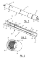
- An installation 1 for connecting a number of pipes 3 to form a pipe string 2 and/or disassembling a pipe string 2 into pipes 3 comprises a hollow body 4 which is placed on a borehole 5 and through which pipes 3 can be carried ( fig. 1 ).
- Hollow body 4 is formed by a stack of modules, including a number of blow-out preventers (BOPs) 6, 7, 8, i.e. hydraulically controllable valves, and two gate valves 9.
- BOPs blow-out preventers
- Each module 6-9 has a tubular channel 46, and these channels 46 together form a passage for pipe string 2.
- Such a stack of BOPs is often referred to as a "Christmas tree".
- Each BOP 6, 7 is provided on either side with hydraulic cylinders 10 in which pistons 11 which operate an active member or ram 12 are movable. These active members or rams 12 are formed differently depending on the function they fulfil.
- the different modules 5-9 are each provided at their outer ends with flanges 13, 14 which are attached liquid-tightly to each other, for instance by bolts.
- Installation 1 further comprises a stackable pipe or "lubricator" 15 mounted on the upper BOP 9.
- Installation 1 further comprises a lifting gear (not shown) with a hoisting cable 16 with which pipes 3 can be inserted into or lifted out of hollow body 4.
- a device 17 Suspended from hoisting cable 16 is a device 17 which is intended to engage on the upper outer end of pipe string 2 for connection thereof to hoisting cable 16.
- This connecting system 18 comprises for each pair of successive pipes 3 a tubular coupling member 19 for arranging therebetween.
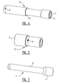
- the tubular coupling member 19 comprises a clamp or snap part 20 for arranging on one of the pipes 3 for connecting and a base part 21 co-acting therewith and for screwing onto the other of the pipes 3 for connecting ( fig. 2, 3 ).
- the clamp or snap part - here clamp part 20 - is provided with an end segment 22 with internal screw thread 23 with which it can be screwed round the narrowed outer end with external screw thread of one of the two pipes 3 to be connected to each other.
- Clamp part 20 is configured here to receive a narrowed outer end 24 with smooth outer surface of base part 21.
- This base part 21 has on the other side a widened outer end 25 with internal screw thread 26 with which it can be screwed onto the narrowed outer end with external screw thread of the other pipe 3.
- This widening 25 also defines a stop which bounds the insertion depth of base part 21 into clamp part 20.
- a movable clamping element 27 which in the shown example takes the form of a ring which substantially wholly encloses the outer surface of outer end 24 of base part 21.
- Clamping ring 27 has a gap 28 ( fig. 6 ) whereby it can be pressed together around outer end 24.
- Clamping ring 27 further has a tapering cross-section with a smooth outer side 29 and a rough inner side 30 which engages on the outer surface of base part 21.
- the outer side 29 of clamping ring 27 co-acts with an inner surface 31 of clamp part 20, which likewise takes a wedge-shaped form.
- Clamping ring 27 is thus pressed increasingly further together as it is moved in the direction of a mouth 32 of clamp part 20, whereby the rough inner side 30 thereof grips increasingly more strongly on base part 21. This prevents base part 21 being pulled out of clamp part 20.
- the inner side 30 of clamping ring 27 takes a sawtooth-like form in order to make the frictional force on outer end 24 as great as possible.
- clamping ring 27 lies loosely round the outer end 24 thereof in the tapering space bounded by the inclining inner surface 31.
- Base part 21 can hereby rotate in clamp part 20.
- End segment 22 of the tubular coupling member 19 is attached to the rest of coupling member 19 in the shown example such that the outer ends of pipes 3 can be detached from each other by exerting a great force such that coupling member 19 fails at the position of the connection to end segment 22. This prevents pipes 3 breaking or installation 1 being damaged.
- the connection intended as failure location is formed by three failing members 33, here bolts, which are screwed into openings 34 in clamp part 20 and openings 35 in end segment 22 in order to attach these two parts to each other.
- clamp member 20 does not consist of two parts connected by failing members, it is also possible to envisage a local weakening being formed therein by giving the wall or casing of clamp member 20 a thinner form locally or by forming a gap therein.
- clamp member 20 In the shown example the components of clamp member 20 are not purely cylindrical, but profiled. End segment 22 and clamp part 20 are thus each provided on their inner side with a peripheral groove 36 and 37 respectively. These grooves 36, 37, also referred to as fishing necks, serve for engagement by an internal tool 38 which forms part of engaging device 17 suspended from hoisting cable 16. This tool 39, with which coupling member 19 and the pipes 3 connected thereby are moved up or downward in borehole 5, is referred to as a running tool or pulling tool.
- clamp member 20 is provided on its outer side with a peripheral groove 38. This outer groove 38 serves for engagement by a fixation member of installation 1 to be discussed below.
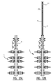
- modules of BOPs 6, 7 of installation 1 are provided with different types of active members or rams 12.
- the form, dimensions and embodiment of these rams 12 vary depending on the function they fulfil in respectively assembly and disassembly of pipe string 2.
- Rams 12A in the lower BOP 6 are thus so-called shear rams which serve to cut through a pipe string 2 and to close the hollow body 4 in the case of a sudden pressure buildup in borehole 5.
- These shear rams 12A are therefore provided with a cutting edge and are embodied so that together or individually they cover the whole cross-section of channel 46 in sealing manner.
- the associated cylinders 10A and pistons 11A also take a larger form than those of the other rams 12B-12E.
- rams 12B-12E are intended for co-action in some form or other with pipe string 2, and therefore all have a ring segment part 46, the dimensions of which are adapted to those of a relevant part of pipe string 2.
- Each ram 12C has a ring or tube segment 40C which is fixed to a bracket 41C, which is in turn fixed to a piston rod 42C of piston 11C.
- Each bracket 41C is provided with two grooves 43C, one of which carries two inserts 44C which can be received close-fittingly in a groove 43C of the opposite ram 12C.
- a strong connection between the two mutually facing rams 12C can in this way be effected when they are both extended into channel 46 of the associated BOP 7.
- Brackets 41C and tube segments 40C close the passage of channel 46 here so that only the internal section bounded by tube segments 40 still remains clear for throughfeed of components of pipe string 2.
- the dimensions selected for the ring or tube segments 40C are slightly larger here than the external diameter of pipes 3 but slightly smaller than the external diameter of coupling members 19.
- the upper pair of rams 12D in the double BOP 7 is intended as fixation members (holding rams) and is configured to engage on the narrowed part or groove 38 in the outer wall of coupling member 19.
- each ram 12D is provided with an insert 47 of a softer, somewhat deformable material which is received in a groove 48 extending over the whole width of bracket 41D and ring segment 40D.
- These rams 12D are also each provided with recesses 43D and protruding parts 44D which lie opposite each other and ensure a firm connection.
- Bracket 41D further has a groove 49 which, when rams 12D lie against each other, runs along the periphery of channel 46. Arranged in this groove 49 is a sealing member 50, likewise of a relatively softer and more readily deformable material than the rest of ram 12D.
- Rams 12E serve as release members (release rams) and are configured for co-action with tool 39 with which pipe string 2 is attached to hoisting cable 16.
- These rams 12E have a construction similar to that of rams 12C forming the support members, but are covered on the inner side of the ring or tube segments 40E with a slide layer 52 of wear-resistant material, for instance a plastic such as HMPE.
- a clamp part 20 of a coupling member 19 is then attached to a pipe 3 and this coupling member 19 is connected by means of an engaging device 17 to hoisting cable 16.
- the assembly of pipe 3, clamp part 20 and engaging device 17 is carried into a lubricator 15 which is closed on one side and which is then attached with its open end to the upper flange of hollow body 4 ( fig. 12B ).
- the pressure in the interior of lubricator 15 is then equalized to that in hollow body 4 and gate valve 9 is opened.
- the closed outer end of lubricator 15 now therefore forms the seal of the combination of hollow body 4 and lubricator 15 ( fig. 12C ).
- the hoisting cable 16 which extends through the closed outer end of lubricator 15, is then payed out until about half the pipe 3 has passed through the rams 12C functioning as support members.
- the weight of pipe 3 is measured and recorded here.
- Support members 12C are then extended into channel 46 by operating the associated hydraulic cylinders 10C and pistons 11C ( fig. 12D ).
- the ring or tube segments 40C now enclose pipe 3 with some play.
- the correct extent to which support members 12C extend can be monitored by measuring or marking the displacement of the relevant piston rods 42C.
- Hoisting cable 16 is subsequently payed out further so that pipe 3 sinks further into hollow body 4 until the bottom edge 51 of clamp part 20 comes to rest on support members 12C ( fig. 12E ).
- the upper edges 12D of the double BOP 7 are then extended into channel 46 by operating the associated hydraulic cylinders 10D and pistons 11D.
- These rams 12D form fixation members which, as stated, engage on the narrowed part or the groove 38 in the outer wall of clamp part 20.
- the correct extent of closure of fixation members 12D is here also measured or marked, for instance on the basis of the displacement of piston rods 42D ( fig. 12F ).
- the upper rams 12E are then extended and enclose engaging device 17 with their ring or tube segments 40E. Because the ring or tube segments 40E are covered with slide layer 52, components of engaging device 17 can be moved up and down to some extent herein when this engaging device 17 is released from pipe 3, so that these rams function as release members.
- engaging device 17 comprises a tool 39 which engages with its lower outer end in mouth 32 of clamping member 19.
- Tool 39 is provided with protrusions 53 which, through displacement of an internal wedge mechanism, are pressed outward and thus engage in groove 37 in clamp part 20. Protrusions 53 are fixed in the protruding position.
- the tool 39 is further provided with a breaking pin 45 and an internal striking mechanism or "jar". When the jar is operated the breaking pin 45 fails, whereby the different components of the wedge mechanism can be moved back to their starting position and protrusions 53 can be retracted. In this position the tool 39 can be taken out of the internal groove 37 of clamp part 20.
- the above discussed release rams 12E are in fact not necessary. These come into play only when use is made of a tool (not shown here) that is not provided with a jar.
- Lubricator 15 with the subsequent pipe part 3 therein can then be attached to hollow body 4 for the purpose of assembling a pipe string 2.
- the new pipe part 3 is attached on its upper side to clamp part 20.
- a base part 21 for co-action with clamp part 20 of the already placed pipe 3 ( fig. 12J ).
- the pressure in hollow body 4 and lubricator 15 is then once again equalized, and gate valve 9 opened.
- the closed end of lubricator 15 now thus once again forms the seal of borehole 5.
- Hoisting cable 16 is then payed out quickly, whereby pipe 3 with pipe part 21 on its lower end lands on clamp part 20 with a considerable force under the influence of its weight.
- Base part 21 protrudes here into clamping ring 27 of clamp part 20.
- clamping ring 27 is moved upward in clamp part 20 and pressed together increasingly tighter round base part 21.
- connection withstands this pulling test the fixation members or rams 12D are moved apart, whereby coupling member 19 is released.
- the thus assembled pipe string 2 is then raised to some extent by tensioning hoisting cable 16 and the weight of pipe string 2 is measured and recorded.
- Support members 12C are then moved apart ( fig. 12L ).
- Hoisting cable 16 is subsequently payed out so that pipe string 2 sinks through about half a pipe length (in this case about four metres) ( fig. 12M ).
- the centre of upper pipe 3 is then once again situated roughly at the height of support members 12C, just as in the situation of fig. 12D .
- Engaging device 17, the breaking pin 54 of which has after all failed, can then be removed again from hoisting cable 16 and replaced by a new engaging device 17 with new pipe 3 and new base part 21, after which the procedure can in fact be repeated from fig. 12J .
- Installation 1 can also be used to lift a pipe string 2 out of borehole 5 and disassemble it into individual pipes 3.
- the starting point here is a situation in which pipe string 2 is suspended from upper pipe 3 in borehole 5 ( fig. 13A ).
- Clamp part 20 rests here with its bottom edge 51 on the extended support members 12C, while pipe 3 is in addition held fast by a pair of rams 12B which are placed between support members 12C and shear rams 12A and which serve as lower fixation members (slip rams).
- hollow body 4 is closed by the upper gate valve 9.
- an engaging device 17 is first attached to hoisting cable 16 and received into lubricator 15 which is then attached to hollow body 4 ( fig. 13B ). The pressure in hollow body 4 and lubricator 15 is then equalized and gate valve 9 is opened ( fig. 13C ). Hosting cable 16 is subsequently payed out, whereby engaging device 17 lands on clamp part 20. The lower outer end of tool 39 engages here in clamp part 20 and is fixed in groove 37 ( fig. 13D ).
- the jar in tool 39 is then activated, whereby clamp part 20 is subjected to an impact load and the failing members 33 eventually fail. Clamp part 20 is thus separated from end segment 22, which remains attached to the upper side of pipe 3. Clamp part 20 is now lifted out of the hollow body and into lubricator 15 ( fig. 13E ), after which jar 15 is isolated from hollow body 4 and detached ( fig. 13F , G ). An engaging device with a smaller tool 39A - for instance with a nominal diameter of 2.5 inches where that of the larger tool can be 3 inches - is then attached to hoisting cable 16 and received in lubricator 15. Lubricator 15 is once again attached to hollow body 4 ( fig. 13H ), the pressure is equalized ( fig.
- fixation members 12B are detached and pipe string 2 is raised over a small part of a pipe length. The weight is measured and recorded here. Support members 12C are then moved apart, whereby pipe string 2 hangs completely freely in hollow body 4, supported only by hoisting cable 16 ( fig. 13K ). Pipe string 2 is then raised so far that the following coupling member 19 between two pipes 3 is situated above support members 12C. This is checked on the basis of a measurement of the length of retracted hoisting cable ( fig. 13L ). Support members 12C are then extended again ( fig. 13M ) and the pipe string is lowered until it rests with bottom edge 51 of coupling member 19 on support members 12C. The lower fixation members 12B are then extended and once again engage on the wall of pipe 3 ( fig. 13N ).
- a pipe string 2 can thus be assembled or disassembled in rapid and simple manner. Operation can take place very quickly through the use of the clamp connection between two parts 20, 21 of coupling member 19, which can each be pre-attached to a corresponding pipe part 3. Failing pins 33 in coupling member 19 on the other hand make it possible to also take the pipes 3 apart again quickly and easily without the danger of damage being caused to pipes 3, to the actual coupling member 19 or to the rest of installation 1.
Abstract
a) inserting a pipe wholly into the borehole,
b) connecting a lower outer end of a subsequent pipe to an upper outer end of the inserted pipe,
c) carrying the thus formed pipe string downward over a pipe length into the borehole, and
d) repeating steps b) and c) as required.
a) connecting a hoisting cable to an upper outer end of the upper pipe of the pipe string,
b) lifting the pipe string over substantially a pipe length in the hollow body and/or the borehole,
c) supporting the lifted pipe string in the hollow body,
d) releasing a connection between the upper pipe and a subsequent pipe of the pipe string,
e) lifting the released upper pipe out of the hollow body, and
f) repeating steps a) to e) as required.
Description
- The invention relates to a method and an installation for assembling or disassembling a pipe string.
- The invention relates more particularly to a method for assembling a pipe string in a borehole, comprising the steps of:
- a) inserting a pipe substantially wholly into the borehole,
- b) connecting a lower outer end of a subsequent pipe to an upper outer end of the inserted pipe,
- c) carrying the thus formed pipe string downward over substantially a pipe length into the borehole, and
- d) repeating steps b) and c) as required.
- Such a method is generally known. Use is made in the known method of pipes with one outer end which is narrowed and provided with external screw thread, while the other outer end is widened and has internal screw thread. The pipes can thus be connected to each other by screwing the narrowed outer end of the one pipe into the widened outer end of the other pipe.
- This method has the drawback that it is difficult to apply in situations where the pipe string has to be assembled in an active borehole, i.e. a borehole in which a pressure prevails which counteracts the insertion of the pipe string. Particularly when the pipe string consists of perforated pipes, so-called screens, the forming of the screw connection between the pipes in an active borehole results in problems.
- The invention therefore has for its object to provide a method of the above described type wherein these problems no longer occur, or at least occur to lesser extent. According to the invention this is achieved in such a method in that the pipe is inserted into the hollow body in step a) while suspended from a hoisting cable, the pipes are connected in step b) by a rapid-action coupling, the pipe string is lowered in step c) until it is supported and the hoisting cable is then detached. In contrast to a conventional screw connection a rapid-action coupling - as the term already suggests - can be effected quickly and relatively easily without the pipes having to be rotated for a lengthy period of time relative to each other for this purpose. Through the use of a hoisting cable in combination with support of the pipes it is possible to suffice with a simple installation.
- So that a support does not have to be present continuously, the pipe string is preferably supported in the hollow body by bringing at least one extendable support member into contact with the pipe string. It is recommended for a stable support that support members are extended and brought into contact with the pipe string from two mutually opposite sides.
- A method which can be performed quickly and easily is obtained when the hoisting cable is detached by exerting a pulling force thereon while the pipe string is held fast in the hollow body.
- The advantage of the simple installation is retained when the subsequent pipe is also placed on the inserted pipe in step b) while suspended from a hoisting cable. The pipes can advantageously be connected here in step b) while the inserted pipe is supported.
- A rapid and simple connection is achieved when the pipes are connected in step b) by clamping or snapping.
- Since pressure force cannot be exerted with a hoisting cable, it is recommended that the clamp or snap connection is formed in step b) by loading an upper outer end of the subsequent pipe in shock-wise manner.
- In order to prevent the pipe string breaking apart in undesirable manner and sinking into the borehole, the connection between the pipes is preferably tested prior to step c) by exerting a determined pulling force on the hoisting cable.
- In order to allow unimpeded lowering of the pipe string the at least one support member can be retracted prior to step c).
- Again with a view to simple installation, the pipe string is preferably inserted into the borehole in step c) while suspended from a hoisting cable.
- In order to allow application of the method without costly modifications to the pipes, which are in any case preferably standardized as far as possible, the pipes can be connected in step b) via a tubular coupling member.
- When the coupling member comprises two parts to be clamped or snapped together, and prior to step b) a part is arranged on the upper outer end of the inserted pipe and the other part on the lower outer end of the subsequent pipe, the connection can be prepared without assembly of the pipe string thereby being slowed down.
- Each part of the coupling member is preferably arranged releasably on the associated pipe so that the pipes and coupling members can be used more than once.
- The invention also relates to a method with which the pipe string can be pulled out of the borehole again and taken apart. Such a method for removal from a borehole and disassembly of a pipe string, an upper pipe of which is at least partially situated in a hollow body placed on the borehole, comprises according to the invention the steps of:
- a) connecting a hoisting cable to an upper outer end of the upper pipe of the pipe string,
- b) lifting the pipe string over substantially a pipe length in the hollow body and/or the borehole,
- c) supporting the lifted pipe string in the hollow body,
- d) releasing a connection between the upper pipe and a subsequent pipe of the pipe string,
- e) lifting the released upper pipe out of the hollow body, and
- f) repeating steps a) to e) as required.
- In order to prevent damage to the pipes here, the connection can be released in step d) by forcing a tubular coupling member connecting the pipes.
- When disassembly begins, a coupling member arranged on the upper pipe can be forced prior to step a) and the hoisting cable can be connected to a segment of the coupling member remaining on the upper pipe.
- The coupling member can be forced relatively easily by shock-wise loading thereof until it fails.
- The invention also relates to an installation for connecting a number of pipes to form a pipe string and/or disassembling a pipe string into pipes. Such an installation comprises according to the invention a hollow body for placing on a borehole and through which the pipes can be carried, a lifting gear with hoisting cable for inserting or lifting the pipes into or out of the hollow body, and a device for supporting at least one of the pipes in the hollow body.
- The supporting device of the installation can advantageously comprise here at least one support member extendable into the hollow body, and preferably two support members extendable from mutually opposite sides into the hollow body.
- The installation can further be provided with a device for fixing the pipe/pipes in the hollow body. The pipes can thus be held in place during the different operations.
- This fixation device preferably comprises at least one pair of mutually opposite fixation members extendable into the hollow body and configured to engage clampingly on the pipe/pipes.
- The installation is preferably provided with a releasable system for connecting successive pipes. This connecting system can advantageously comprise a tubular coupling member for arranging in each case between two successive pipes.
- A structurally simple solution is achieved here when each coupling member comprises two parts which are clamped or snapped onto each other and which are attachable to mutually facing outer ends of two successive pipes.
- In order to enable easy release of the connection between successive pipes each coupling member can comprise an end segment which is attached by at least one failing member to the rest of the coupling member.
- The installation can further be provided with a device connected to the hoisting cable for engaging on the upper outer end of a pipe or coupling member, for instance in the form of a tool which can be clamped in the upper outer end of a pipe or coupling member. Using such an internal tool the pipes can be connected quickly and easily to the hoisting cable in order to be lowered into or lifted out of the borehole.
- Finally, the installation can advantageously be provided with a device connected to the hoisting cable for exerting a shock-wise load on the pipes/pipes. Clamp or snap connections can hereby be realized or, conversely, connections can be broken. A structurally simple solution is achieved when the loading device comprises a striking tool or "jar". This type of striking tool is available in many types and sizes.
- The invention further relates to a coupling member for use in a method as described above. The invention provides for this purpose a tubular coupling member for connecting to each other mutually facing outer ends of two successive pipes of a pipe string, comprising a base part for connecting to one of two successive pipes and a clamp or snap part for connecting to the other pipe and receiving the base part.
- As already indicated above, the connecting member according to the invention is preferably provided with at least one clamp or snap element which is accommodated movably in the clamp or snap part and which engages on an outer surface of the base part. A very strong connection which is easy to form is obtained when the at least one clamp or snap element and/or an inner surface of the clamp or snap part co-acting therewith is wedge-shaped.
- In order to maximize the connecting force in the coupling member the at least one clamp or snap element can be a ring which at least partially encloses the outer surface of the base part and which has a rough surface.
- The clamp or snap part of the tubular coupling member according to the invention preferably comprises an end segment which is attached by at least one failing member to the rest of the clamp or snap part. The connection between the pipes can thus be easily broken by exerting a determined force thereon, this without the pipes or the equipment around the borehole being damaged.
- The invention will now be elucidated on the basis of an example, wherein reference is made to the accompanying drawing, in which:
-
Fig. 1 is a cross-sectional side view of an installation for assembling or disassembling a pipe string according to the invention, -
Fig. 2 is a perspective view of a coupling member according to the invention with a base part and a clamp or snap part, -
Fig. 3 is a perspective view in longitudinal section of the coupling member offig. 2 , -
Fig. 4 is a view corresponding tofig. 2 of the clamp or snap part of the coupling member, -
Fig. 5 is a view corresponding tofig. 2 of the end segment of the coupling member, -
Fig. 6 is a perspective view of a clamping element of the coupling member, -
Fig. 7 is a perspective view of the base part of the coupling member, -
Fig. 8 is a perspective view of a pair of support members for use in the installation offig. 1 , -
Fig. 9 is a perspective view with exploded parts of a pair of fixation members of the installation, -
Fig. 10 is a view corresponding tofig. 8 of a pair of release members of the installation, -
Fig. 11 is a longitudinal section through an engaging device for use in the installation, -
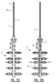
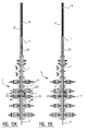
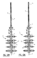
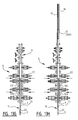
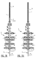
Fig. 12A-R show schematic representations of the different steps of the method according to the invention for assembling a pipe string in a borehole, and -
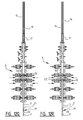
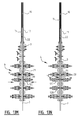
Fig. 13A-P show schematically the different steps of the method for lifting the pipe string out of the borehole and disassembly thereof. - An installation 1 for connecting a number of
pipes 3 to form a pipe string 2 and/or disassembling a pipe string 2 intopipes 3 comprises ahollow body 4 which is placed on aborehole 5 and through whichpipes 3 can be carried (fig. 1 ).Hollow body 4 is formed by a stack of modules, including a number of blow-out preventers (BOPs) 6, 7, 8, i.e. hydraulically controllable valves, and twogate valves 9. Each module 6-9 has a tubular channel 46, and these channels 46 together form a passage for pipe string 2. Such a stack of BOPs is often referred to as a "Christmas tree". - Each
BOP hydraulic cylinders 10 in which pistons 11 which operate an active member or ram 12 are movable. These active members or rams 12 are formed differently depending on the function they fulfil. The different modules 5-9 are each provided at their outer ends withflanges upper BOP 9. - Installation 1 further comprises a lifting gear (not shown) with a hoisting
cable 16 with whichpipes 3 can be inserted into or lifted out ofhollow body 4. Suspended from hoistingcable 16 is adevice 17 which is intended to engage on the upper outer end of pipe string 2 for connection thereof to hoistingcable 16. For the purpose of mutual connection ofsuccessive pipes 3 use is made in the shown example of a releasable connecting system 18. This connecting system 18 comprises for each pair of successive pipes 3 atubular coupling member 19 for arranging therebetween. - The
tubular coupling member 19 comprises a clamp or snappart 20 for arranging on one of thepipes 3 for connecting and abase part 21 co-acting therewith and for screwing onto the other of thepipes 3 for connecting (fig. 2, 3 ). The clamp or snap part - here clamp part 20 - is provided with anend segment 22 withinternal screw thread 23 with which it can be screwed round the narrowed outer end with external screw thread of one of the twopipes 3 to be connected to each other. Clamppart 20 is configured here to receive a narrowedouter end 24 with smooth outer surface ofbase part 21. Thisbase part 21 has on the other side a widenedouter end 25 withinternal screw thread 26 with which it can be screwed onto the narrowed outer end with external screw thread of theother pipe 3. This widening 25 also defines a stop which bounds the insertion depth ofbase part 21 intoclamp part 20. - Received in
clamp part 20 is amovable clamping element 27 which in the shown example takes the form of a ring which substantially wholly encloses the outer surface ofouter end 24 ofbase part 21. Clampingring 27 has a gap 28 (fig. 6 ) whereby it can be pressed together aroundouter end 24. Clampingring 27 further has a tapering cross-section with a smoothouter side 29 and a roughinner side 30 which engages on the outer surface ofbase part 21. Theouter side 29 of clampingring 27 co-acts with an inner surface 31 ofclamp part 20, which likewise takes a wedge-shaped form. Clampingring 27 is thus pressed increasingly further together as it is moved in the direction of amouth 32 ofclamp part 20, whereby the roughinner side 30 thereof grips increasingly more strongly onbase part 21. This preventsbase part 21 being pulled out ofclamp part 20. In the shown example theinner side 30 of clampingring 27 takes a sawtooth-like form in order to make the frictional force onouter end 24 as great as possible. - As long as no pulling force in the direction of
mouth 32 is exerted onbase part 21, clampingring 27 lies loosely round theouter end 24 thereof in the tapering space bounded by the inclining inner surface 31.Base part 21 can hereby rotate inclamp part 20. -
End segment 22 of thetubular coupling member 19 is attached to the rest of couplingmember 19 in the shown example such that the outer ends ofpipes 3 can be detached from each other by exerting a great force such thatcoupling member 19 fails at the position of the connection to endsegment 22. This preventspipes 3 breaking or installation 1 being damaged. The connection intended as failure location is formed by three failingmembers 33, here bolts, which are screwed intoopenings 34 inclamp part 20 andopenings 35 inend segment 22 in order to attach these two parts to each other. Whenclamp member 20 does not consist of two parts connected by failing members, it is also possible to envisage a local weakening being formed therein by giving the wall or casing of clamp member 20 a thinner form locally or by forming a gap therein. - In the shown example the components of
clamp member 20 are not purely cylindrical, but profiled.End segment 22 and clamppart 20 are thus each provided on their inner side with aperipheral groove grooves internal tool 38 which forms part of engagingdevice 17 suspended from hoistingcable 16. Thistool 39, with whichcoupling member 19 and thepipes 3 connected thereby are moved up or downward inborehole 5, is referred to as a running tool or pulling tool. In addition,clamp member 20 is provided on its outer side with aperipheral groove 38. Thisouter groove 38 serves for engagement by a fixation member of installation 1 to be discussed below. - As stated, the modules of
BOPs rams 12 vary depending on the function they fulfil in respectively assembly and disassembly of pipe string 2. - Rams 12A in the
lower BOP 6 are thus so-called shear rams which serve to cut through a pipe string 2 and to close thehollow body 4 in the case of a sudden pressure buildup inborehole 5. These shear rams 12A are therefore provided with a cutting edge and are embodied so that together or individually they cover the whole cross-section of channel 46 in sealing manner. In view of the great forces which have to be developed by shear rams 12A, the associated cylinders 10A andpistons 11A also take a larger form than those of theother rams 12B-12E. - These
other rams 12B-12E are intended for co-action in some form or other with pipe string 2, and therefore all have a ring segment part 46, the dimensions of which are adapted to those of a relevant part of pipe string 2. - Shown in
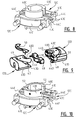
fig. 8 are tworams 12C which face toward each other and which function in installation 1 as support members (tagging rams) as will be elucidated below. Eachram 12C has a ring ortube segment 40C which is fixed to abracket 41C, which is in turn fixed to a piston rod 42C ofpiston 11C. Eachbracket 41C is provided with two grooves 43C, one of which carries twoinserts 44C which can be received close-fittingly in a groove 43C of theopposite ram 12C. - A strong connection between the two mutually facing
rams 12C can in this way be effected when they are both extended into channel 46 of the associatedBOP 7.Brackets 41C andtube segments 40C close the passage of channel 46 here so that only the internal section bounded by tube segments 40 still remains clear for throughfeed of components of pipe string 2. The dimensions selected for the ring ortube segments 40C are slightly larger here than the external diameter ofpipes 3 but slightly smaller than the external diameter ofcoupling members 19. When the rams orsupport members 12C are extended, pipe string 2 can thus be moved up and downward up to the point where acoupling member 19 comes into contact withsupport members 12C. - The upper pair of
rams 12D in thedouble BOP 7 is intended as fixation members (holding rams) and is configured to engage on the narrowed part or groove 38 in the outer wall of couplingmember 19. In order to prevent damage to couplingmember 19 eachram 12D is provided with aninsert 47 of a softer, somewhat deformable material which is received in agroove 48 extending over the whole width ofbracket 41D andring segment 40D. Theserams 12D are also each provided withrecesses 43D and protrudingparts 44D which lie opposite each other and ensure a firm connection.Bracket 41D further has agroove 49 which, when rams 12D lie against each other, runs along the periphery of channel 46. Arranged in thisgroove 49 is a sealingmember 50, likewise of a relatively softer and more readily deformable material than the rest ofram 12D. -
Rams 12E (fig. 10 ) serve as release members (release rams) and are configured for co-action withtool 39 with which pipe string 2 is attached to hoistingcable 16. Theserams 12E have a construction similar to that oframs 12C forming the support members, but are covered on the inner side of the ring ortube segments 40E with aslide layer 52 of wear-resistant material, for instance a plastic such as HMPE. - The assembly of a pipe string 2 in
borehole 5 making use of installation 1 now proceeds as follows. - In the starting situation the
hollow body 4 is placed onborehole 5 and closed by theupper gate valve 9. Allother BOPs hollow body 4 as in borehole 5 (indicated schematically by the dark shading infig. 12A ). - A
clamp part 20 of acoupling member 19 is then attached to apipe 3 and thiscoupling member 19 is connected by means of an engagingdevice 17 to hoistingcable 16. The assembly ofpipe 3, clamppart 20 and engagingdevice 17 is carried into alubricator 15 which is closed on one side and which is then attached with its open end to the upper flange of hollow body 4 (fig. 12B ). The pressure in the interior oflubricator 15 is then equalized to that inhollow body 4 andgate valve 9 is opened. The closed outer end oflubricator 15 now therefore forms the seal of the combination ofhollow body 4 and lubricator 15 (fig. 12C ). - The hoisting
cable 16, which extends through the closed outer end oflubricator 15, is then payed out until about half thepipe 3 has passed through therams 12C functioning as support members. The weight ofpipe 3 is measured and recorded here.Support members 12C are then extended into channel 46 by operating the associatedhydraulic cylinders 10C andpistons 11C (fig. 12D ). The ring ortube segments 40C now enclosepipe 3 with some play. The correct extent to whichsupport members 12C extend can be monitored by measuring or marking the displacement of the relevant piston rods 42C. - Hoisting
cable 16 is subsequently payed out further so thatpipe 3 sinks further intohollow body 4 until thebottom edge 51 ofclamp part 20 comes to rest onsupport members 12C (fig. 12E ). Theupper edges 12D of thedouble BOP 7 are then extended into channel 46 by operating the associatedhydraulic cylinders 10D andpistons 11D. Theserams 12D form fixation members which, as stated, engage on the narrowed part or thegroove 38 in the outer wall ofclamp part 20. The correct extent of closure offixation members 12D is here also measured or marked, for instance on the basis of the displacement ofpiston rods 42D (fig. 12F ). - The
upper rams 12E are then extended and enclose engagingdevice 17 with their ring ortube segments 40E. Because the ring ortube segments 40E are covered withslide layer 52, components of engagingdevice 17 can be moved up and down to some extent herein when this engagingdevice 17 is released frompipe 3, so that these rams function as release members. - As stated, engaging
device 17 comprises atool 39 which engages with its lower outer end inmouth 32 of clampingmember 19.Tool 39 is provided withprotrusions 53 which, through displacement of an internal wedge mechanism, are pressed outward and thus engage ingroove 37 inclamp part 20.Protrusions 53 are fixed in the protruding position. In the shown example thetool 39 is further provided with a breakingpin 45 and an internal striking mechanism or "jar". When the jar is operated the breakingpin 45 fails, whereby the different components of the wedge mechanism can be moved back to their starting position andprotrusions 53 can be retracted. In this position thetool 39 can be taken out of theinternal groove 37 ofclamp part 20. When such a tool with jar is used, the above discussed release rams 12E are in fact not necessary. These come into play only when use is made of a tool (not shown here) that is not provided with a jar. - Once engaging
device 17 has been released in this manner fromclamp part 20 theupper rams 12E are once again moved apart, whereby the associated channel is left clear. Hoistingcable 16 is then taken in, whereby engagingdevice 17 is pulled out of the hollow body into thelubricator 15 placed thereon (fig. 12H ).Hollow body 4 can then be isolated fromlubricator 15 by closing the upper gate valve 9 (fig. 12I ).Lubricator 15 can then be detached and asubsequent pipe 3 withclamp part 20 can be attached to a new engagingdevice 17 and subsequently pulled intolubricator 15. -
Lubricator 15 with thesubsequent pipe part 3 therein can then be attached tohollow body 4 for the purpose of assembling a pipe string 2. As stated, thenew pipe part 3 is attached on its upper side to clamppart 20. Further mounted on the underside of thisnew pipe part 3 is abase part 21 for co-action withclamp part 20 of the already placed pipe 3 (fig. 12J ). The pressure inhollow body 4 andlubricator 15 is then once again equalized, andgate valve 9 opened. The closed end oflubricator 15 now thus once again forms the seal ofborehole 5. - Hoisting
cable 16 is then payed out quickly, wherebypipe 3 withpipe part 21 on its lower end lands onclamp part 20 with a considerable force under the influence of its weight.Base part 21 protrudes here into clampingring 27 ofclamp part 20. By now activating the jar in engagingdevice 17 thepipe 3 withpipe part 21 is then jarred up and downward to some extent, whereby clampingring 27 is moved upward inclamp part 20 and pressed together increasingly tighterround base part 21. Once a firm connection has thus been formed betweenclamp part 20 andbase part 21, and therefore between the twopipes 3 attached thereto, this connection is tested by exerting a pulling force on hoisting cable 16 (fig. 12K ). - If the connection withstands this pulling test the fixation members or rams 12D are moved apart, whereby coupling
member 19 is released. The thus assembled pipe string 2 is then raised to some extent by tensioning hoistingcable 16 and the weight of pipe string 2 is measured and recorded.Support members 12C are then moved apart (fig. 12L ). Hoistingcable 16 is subsequently payed out so that pipe string 2 sinks through about half a pipe length (in this case about four metres) (fig. 12M ). The centre ofupper pipe 3 is then once again situated roughly at the height ofsupport members 12C, just as in the situation offig. 12D . - The weight of pipe string 2 is then determined again,
support members 12C are extended again (fig. 12N ) and pipe string 2 is lowered until the followingcoupling member 19 comes to rest onsupport members 12C (fig. 12O ).Fixation members 12D are subsequently extended again so as to engage on the narrowedpart 38 ofcoupling member 19. The tension is removed from hoistingcable 16 in order to establish whether pipe string 2 is reliably suspended inhollow body 4. Theupper rams 12E are then extended in order to stabilize the tool 39 (fig. 12P ), after which this latter can be detached fromclamp part 20.Upper rams 12E are then moved apart again and engagingdevice 17 is pulled upward out ofhollow body 4 intolubricator 15 by hoisting cable 16 (fig. 12Q ).Hollow body 4 can then be isolated again from lubricator 15 (fig. 12R ), after which this pipe can be taken fromhollow body 4. -
Engaging device 17, the breaking pin 54 of which has after all failed, can then be removed again from hoistingcable 16 and replaced by a new engagingdevice 17 withnew pipe 3 andnew base part 21, after which the procedure can in fact be repeated fromfig. 12J . - Installation 1 can also be used to lift a pipe string 2 out of
borehole 5 and disassemble it intoindividual pipes 3. The starting point here is a situation in which pipe string 2 is suspended fromupper pipe 3 in borehole 5 (fig. 13A ). Clamppart 20 rests here with itsbottom edge 51 on theextended support members 12C, whilepipe 3 is in addition held fast by a pair oframs 12B which are placed betweensupport members 12C and shear rams 12A and which serve as lower fixation members (slip rams). In this situationhollow body 4 is closed by theupper gate valve 9. - In order to remove pipe string 2 from
borehole 5 an engagingdevice 17 is first attached to hoistingcable 16 and received intolubricator 15 which is then attached to hollow body 4 (fig. 13B ). The pressure inhollow body 4 andlubricator 15 is then equalized andgate valve 9 is opened (fig. 13C ). Hostingcable 16 is subsequently payed out, whereby engagingdevice 17 lands onclamp part 20. The lower outer end oftool 39 engages here inclamp part 20 and is fixed in groove 37 (fig. 13D ). - The jar in
tool 39 is then activated, wherebyclamp part 20 is subjected to an impact load and the failingmembers 33 eventually fail. Clamppart 20 is thus separated fromend segment 22, which remains attached to the upper side ofpipe 3. Clamppart 20 is now lifted out of the hollow body and into lubricator 15 (fig. 13E ), after whichjar 15 is isolated fromhollow body 4 and detached (fig. 13F ,G ). An engaging device with asmaller tool 39A - for instance with a nominal diameter of 2.5 inches where that of the larger tool can be 3 inches - is then attached to hoistingcable 16 and received inlubricator 15.Lubricator 15 is once again attached to hollow body 4 (fig. 13H ), the pressure is equalized (fig. 13I ) and thenew tool 39A is lowered into end segment 22 (fig. 13J ). The protrusions engage here ingroove 36, whereby pipe string 2 is attached to hoistingcable 16. Force is then applied to hoistingcable 16 in order to test the strength of the connection before the suspension ofpipe 3 is released. - If the connection does indeed appear to be strong enough,
fixation members 12B are detached and pipe string 2 is raised over a small part of a pipe length. The weight is measured and recorded here.Support members 12C are then moved apart, whereby pipe string 2 hangs completely freely inhollow body 4, supported only by hoisting cable 16 (fig. 13K ). Pipe string 2 is then raised so far that the followingcoupling member 19 between twopipes 3 is situated abovesupport members 12C. This is checked on the basis of a measurement of the length of retracted hoisting cable (fig. 13L ).Support members 12C are then extended again (fig. 13M ) and the pipe string is lowered until it rests withbottom edge 51 ofcoupling member 19 onsupport members 12C. Thelower fixation members 12B are then extended and once again engage on the wall of pipe 3 (fig. 13N ). - Once
pipe 3 has been thus fixed, the jar intool 39A is operated once again, whereby an impact load is exerted on couplingmember 19 viaend segment 22 andupper pipe 3. Failingmembers 33 will hereby fail again, whereby the connection between the twopipes 3 is broken.Upper pipe 3 is then raised into lubricator 15 (fig. 13O ), after which thislubricator 15 is again isolated fromhollow body 4 and detached,pipe 3 can be removed therefrom and the hoisting cable and the tool can be made ready to disassemble asubsequent pipe 3 from pipe string 2. - Using installation 1 according to the invention, and making use of
coupling member 19 with the clamp connection as described above, a pipe string 2 can thus be assembled or disassembled in rapid and simple manner. Operation can take place very quickly through the use of the clamp connection between twoparts coupling member 19, which can each be pre-attached to acorresponding pipe part 3. Failing pins 33 incoupling member 19 on the other hand make it possible to also take thepipes 3 apart again quickly and easily without the danger of damage being caused topipes 3, to theactual coupling member 19 or to the rest of installation 1. - Although the invention has been elucidated above on the basis of an example, it will be apparent that it is not limited thereto. It is not therefore strictly necessary to apply a clamp connection, and it would be possible to opt instead for a snap connection, for instance by means of spring-loaded fingers or protrusions. The clamp connection could also be embodied otherwise than shown here, for instance by forming a wedge in the peripheral direction instead of the longitudinal direction of the coupling member. A clamp connection could then be effected between the pipes by means of a small rotation. Finally, it is even possible to envisage dispensing with the use of separate coupling members. The snap or clamp provisions could in that case be arranged in the pipe ends.
- The scope of the invention is therefore defined solely by the following claims.
Claims (15)
- Method for assembling a pipe string in a borehole, comprising the steps of:a) inserting a pipe substantially wholly into a hollow body placed on the borehole,b) connecting a lower outer end of a subsequent pipe to an upper outer end of the inserted pipe,c) carrying the thus formed pipe string downward over substantially a pipe length into the hollow body and/or the borehole, andd) repeating steps b) and c) as required,
characterized in that the pipe is inserted into the hollow body in step a) while suspended from a hoisting cable, the pipes are connected in step b) by a rapid-action coupling, the pipe string is lowered in step c) until it is supported and the hoisting cable is then detached. - Method as claimed in claim 1, characterized in that the pipe string is supported in the hollow body by bringing at least one extendable support member into contact with the pipe string, wherein optionally support members are extended and brought into contact with the pipe string from two mutually opposite sides.
- Method as claimed in any of the foregoing claims, characterized in that the hoisting cable is detached by exerting a pulling force thereon while the pipe string is held fast in the hollow body.
- Method as claimed in any of the foregoing claims, characterized in that the subsequent pipe is placed on the inserted pipe in step b) while suspended from a hoisting cable, wherein optionally the pipes are connected in step b) while the inserted pipe is supported, wherein optionally the pipes are connected in step b) by clamping or snapping, wherein optionally the clamp or snap connection is formed in step b) by loading an upper outer end of the subsequent pipe in shock-wise manner, and wherein the connection between the pipes is tested prior to step c) by exerting a determined pulling force on the hoisting cable.
- Method as claimed in any of the claims 2-4, characterized in that the at least one support member is retracted prior to step c).
- Method as claimed in any of the foregoing claims, characterized in that the pipe string is inserted into the borehole in step c) while suspended from a hoisting cable.
- Method as claimed in any of the foregoing claims, characterized in that the pipes are connected in step b) via a tubular coupling member, wherein optionally the coupling member comprises two parts to be clamped or snapped together, and prior to step b) a part is arranged on the upper outer end of the inserted pipe and the other part on the lower outer end of the subsequent pipe, and wherein optionally each part of the coupling member is arranged releasably on the associated pipe.
- Method for removal from a borehole and disassembly of a pipe string, an upper pipe of which is at least partially situated in a hollow body placed on the borehole, comprising the steps of:a) connecting a hoisting cable to an upper outer end of the upper pipe of the pipe string,b) lifting the pipe string over substantially a pipe length in the hollow body and/or the borehole,c) supporting the lifted pipe string in the hollow body,d) releasing a connection between the upper pipe and a subsequent pipe of the pipe string,e) lifting the released upper pipe out of the hollow body, andf) repeating steps a) to e) as required,
wherein optionally the connection is released in step d) by forcing a tubular coupling member connecting the pipes,
wherein optionally a coupling member arranged on the upper pipe is forced prior to step a) and the hoisting cable is connected to a segment of the coupling member remaining on the upper pipe, and wherein the coupling member is forced by shock-wise loading thereof until it fails. - Installation for connecting a number of pipes to form a pipe string and/or disassembling a pipe string into pipes, comprising a hollow body for placing on a borehole and through which the pipes can be carried, a lifting gear with hoisting cable for inserting or lifting the pipes into or out of the hollow body, and a device for supporting at least one of the pipes in the hollow body.
- Installation as claimed in claim 9, characterized in that the supporting device comprises at least one support member extendable into the hollow body, optionally comprising two support members extendable from mutually opposite sides into the hollow body, and optionally further comprising a device for fixing the pipe/pipes in the hollow body, wherein optionally the fixation device comprises at least one pair of mutually opposite fixation members extendable into the hollow body and configured to engage clampingly on the pipe/pipes.
- Installation as claimed in claim 9 or 10, characterized by a releasable system for connecting successive pipes, wherein optionally the connecting system comprises a tubular coupling member for arranging in each case between two successive pipes, wherein optionally each coupling member comprises two parts which are clamped or snapped onto each other and which are attachable to mutually facing outer ends of two successive pipes, and wherein optionally each coupling member comprises an end segment which is attached by at least one failing member to the rest of the coupling member.
- Installation as claimed in any of the claims 9-11, characterized by a device connected to the hoisting cable for engaging on the upper outer end of a pipe or coupling member, wherein optionally the engaging device comprises a tool which can be clamped in the upper outer end of a pipe or coupling member.
- Installation as claimed in any of the claims 9-12, characterized by a device connected to the hoisting cable for exerting a shock-wise load on the pipes/pipes, wherein optionally the loading device comprises a striking tool or jar.
- Tubular coupling member evidently intended for use in a method as claimed in claim 7 or 8 or in an installation as claimed in claim 11, characterized by a base part for connecting to one of two successive pipes and a clamp or snap part for connecting to the other pipe and receiving the base part, optionally comprising at least one clamp or snap element which is accommodated movably in the clamp or snap part and which engages on an outer surface of the base part, wherein optionally the at least one clamp or snap element and/or an inner surface of the clamp or snap part co-acting therewith is wedge-shaped, and wherein optionally the at least one clamp or snap element is a ring which at least partially encloses the outer surface of the base part and which has a rough inner surface.
- Coupling member as claimed in claim 14, characterized in that the clamp or snap part comprises an end segment which is attached by at least one failing member to the rest of the clamp or snap part.
Applications Claiming Priority (1)
| Application Number | Priority Date | Filing Date | Title |
|---|---|---|---|
| NL2010867A NL2010867C2 (en) | 2013-05-27 | 2013-05-27 | METHOD AND INSTALLATION FOR FORMING OR DISASSEMBLING A TUBE STRENGTH AND A TORQUE TO BE USED THEREOF |
Publications (1)
| Publication Number | Publication Date |
|---|---|
| EP2808481A1 true EP2808481A1 (en) | 2014-12-03 |
Family
ID=49517573
Family Applications (1)
| Application Number | Title | Priority Date | Filing Date |
|---|---|---|---|
| EP13195492.7A Withdrawn EP2808481A1 (en) | 2013-05-27 | 2013-12-03 | Method and installation for assembling or disassembling a pipe string, and coupling member for use therein |
Country Status (2)
| Country | Link |
|---|---|
| EP (1) | EP2808481A1 (en) |
| NL (2) | NL2010867C2 (en) |
Cited By (2)
| Publication number | Priority date | Publication date | Assignee | Title |
|---|---|---|---|---|
| CN105952394A (en) * | 2016-06-21 | 2016-09-21 | 崔斌 | Special elevator structure for pressurized workover of oil-gas field |
| US11319769B2 (en) | 2020-04-30 | 2022-05-03 | Saudi Arabian Oil Company | Multi-intervention blowout preventer and methods of use thereof |
Citations (9)
| Publication number | Priority date | Publication date | Assignee | Title |
|---|---|---|---|---|
| US2721614A (en) * | 1952-04-17 | 1955-10-25 | Drury M Simmons | Systems and structure for controlling the movement of well pipe in well bores |
| US3100015A (en) * | 1959-10-05 | 1963-08-06 | Regan Forge & Eng Co | Method of and apparatus for running equipment into and out of wells |
| US3322443A (en) * | 1964-04-17 | 1967-05-30 | Brown Oil Tools | Quick coupling device for tubular bodies |
| US3361453A (en) * | 1965-07-02 | 1968-01-02 | Brown Oil Tools | Quick coupling device |
| US3999610A (en) * | 1974-11-21 | 1976-12-28 | Otis Engineering Corporation | Pipe snubbing method and apparatus |
| US4119297A (en) * | 1977-03-14 | 1978-10-10 | Gunther Albert W | Snubbing apparatus |
| GB2141509A (en) * | 1983-06-17 | 1984-12-19 | Slope Indicator Co | Coupling for tubular members |
| US5176406A (en) * | 1990-12-20 | 1993-01-05 | Straghan Robert G | Coupling |
| NL1034936C2 (en) * | 2008-01-21 | 2009-07-22 | Balance Point Control B V | Tube forming method for borehole strand, involves inserting end of pipe completely into borehole of tube, and lowering tube shaped strand to length of pipe, where end of tube and end of other tube are linked by clicks or clips |
-
2013
- 2013-05-27 NL NL2010867A patent/NL2010867C2/en not_active IP Right Cessation
- 2013-12-03 EP EP13195492.7A patent/EP2808481A1/en not_active Withdrawn
-
2014
- 2014-11-27 NL NL2013895A patent/NL2013895C2/en not_active IP Right Cessation
Patent Citations (9)
| Publication number | Priority date | Publication date | Assignee | Title |
|---|---|---|---|---|
| US2721614A (en) * | 1952-04-17 | 1955-10-25 | Drury M Simmons | Systems and structure for controlling the movement of well pipe in well bores |
| US3100015A (en) * | 1959-10-05 | 1963-08-06 | Regan Forge & Eng Co | Method of and apparatus for running equipment into and out of wells |
| US3322443A (en) * | 1964-04-17 | 1967-05-30 | Brown Oil Tools | Quick coupling device for tubular bodies |
| US3361453A (en) * | 1965-07-02 | 1968-01-02 | Brown Oil Tools | Quick coupling device |
| US3999610A (en) * | 1974-11-21 | 1976-12-28 | Otis Engineering Corporation | Pipe snubbing method and apparatus |
| US4119297A (en) * | 1977-03-14 | 1978-10-10 | Gunther Albert W | Snubbing apparatus |
| GB2141509A (en) * | 1983-06-17 | 1984-12-19 | Slope Indicator Co | Coupling for tubular members |
| US5176406A (en) * | 1990-12-20 | 1993-01-05 | Straghan Robert G | Coupling |
| NL1034936C2 (en) * | 2008-01-21 | 2009-07-22 | Balance Point Control B V | Tube forming method for borehole strand, involves inserting end of pipe completely into borehole of tube, and lowering tube shaped strand to length of pipe, where end of tube and end of other tube are linked by clicks or clips |
Cited By (2)
| Publication number | Priority date | Publication date | Assignee | Title |
|---|---|---|---|---|
| CN105952394A (en) * | 2016-06-21 | 2016-09-21 | 崔斌 | Special elevator structure for pressurized workover of oil-gas field |
| US11319769B2 (en) | 2020-04-30 | 2022-05-03 | Saudi Arabian Oil Company | Multi-intervention blowout preventer and methods of use thereof |
Also Published As
| Publication number | Publication date |
|---|---|
| NL2013895A (en) | 2015-02-09 |
| NL2010867C2 (en) | 2014-12-17 |
| NL2013895C2 (en) | 2015-07-07 |
Similar Documents
| Publication | Publication Date | Title |
|---|---|---|
| US9644448B2 (en) | Apparatus and method for isolating a section of a pipe riser bore in the course of riser renewal | |
| US8573312B2 (en) | Apparatus for applying an axial force to well pipe slips | |
| BR112017003383B1 (en) | Sealing apparatus for use in a well pipe, system comprising a sealing apparatus and a well pipe and method for using the sealing apparatus in a well pipe | |
| US9777546B2 (en) | Ram packer extraction tool | |
| CA2958296C (en) | Drive off method from subsea well with pipe retention capability | |
| BRPI0717865A2 (en) | CUTTING MODULE FOR SECTIONING A Duct IN A WELL, METHOD FOR SECTIONING A Duct IN A WELL, SYSTEM, METHOD, AND APPARATUS | |
| US8915676B2 (en) | Subsea clamp connector emergency release tool and method | |
| US20100139921A1 (en) | Cutting Device and a Method for Emergency Cutting of a Line in a Well | |
| BR112018004641B1 (en) | APPARATUS FOR TEMPORARILY RETAINING A TENSIONED ROPE, METHOD OF RETAINING A TENSIONED ROPE, METHOD OF RELEASING A TENSIONED ROPE AND METHOD FOR CONNECTING AN ADDITIONAL ITEM OF EQUIPMENT BETWEEN ROPE SECTIONS | |
| EP2808481A1 (en) | Method and installation for assembling or disassembling a pipe string, and coupling member for use therein | |
| RU2694453C1 (en) | Device for lowering cable into well | |
| US6997262B2 (en) | Emergency cutting apparatus and method | |
| US7832480B1 (en) | Apparatus and method for extracting a tubular string from a bore hole | |
| US7431077B2 (en) | Cable hanger for use in a cable guided fishing assembly | |
| AU2014203399A1 (en) | Apparatus and Method for the Installation or Removal of a Rotary Control Device Insert or a Component Thereof | |
| CN209924958U (en) | Small-sized quick cable lifting device with pressure operation pipe column inner cavity | |
| CA2845974C (en) | Rotatable tubing hanger | |
| US20140034333A1 (en) | Lifting device and method | |
| US20140294512A1 (en) | Powered Slip Actuation | |
| AU2020247075B2 (en) | Enhanced method for cutting pipes on a drill floor and tool therefor | |
| GB2553423A (en) | Device and method for suspending loads from a bail of an elevator of a drilling rig, and corresponding drilling rig assembly | |
| US20150136417A1 (en) | Method for handling tubulars and rigidizer therefor | |
| US10895125B2 (en) | Completion interface systems for use with surface BOPS | |
| NO20131685A1 (en) | Process and machinery for operations on, in or through a pipe structure | |
| RU2021493C1 (en) | Method for control of oil and gas shows with cable being in wellbore and device for its realization |
Legal Events
| Date | Code | Title | Description |
|---|---|---|---|
| PUAI | Public reference made under article 153(3) epc to a published international application that has entered the european phase |
Free format text: ORIGINAL CODE: 0009012 |
|
| 17P | Request for examination filed |
Effective date: 20131203 |
|
| AK | Designated contracting states |
Kind code of ref document: A1 Designated state(s): AL AT BE BG CH CY CZ DE DK EE ES FI FR GB GR HR HU IE IS IT LI LT LU LV MC MK MT NL NO PL PT RO RS SE SI SK SM TR |
|
| AX | Request for extension of the european patent |
Extension state: BA ME |
|
| R17P | Request for examination filed (corrected) |
Effective date: 20150603 |
|
| RBV | Designated contracting states (corrected) |
Designated state(s): AL AT BE BG CH CY CZ DE DK EE ES FI FR GB GR HR HU IE IS IT LI LT LU LV MC MK MT NL NO PL PT RO RS SE SI SK SM TR |
|
| STAA | Information on the status of an ep patent application or granted ep patent |
Free format text: STATUS: THE APPLICATION IS DEEMED TO BE WITHDRAWN |
|
| 18D | Application deemed to be withdrawn |
Effective date: 20160701 |