EP2808630A2 - Airtight container for refrigerator and refrigerator including the same - Google Patents
Airtight container for refrigerator and refrigerator including the same Download PDFInfo
- Publication number
- EP2808630A2 EP2808630A2 EP14169997.5A EP14169997A EP2808630A2 EP 2808630 A2 EP2808630 A2 EP 2808630A2 EP 14169997 A EP14169997 A EP 14169997A EP 2808630 A2 EP2808630 A2 EP 2808630A2
- Authority
- EP
- European Patent Office
- Prior art keywords
- ventilation port
- drawer
- case
- closing member
- opening
- Prior art date
- Legal status (The legal status is an assumption and is not a legal conclusion. Google has not performed a legal analysis and makes no representation as to the accuracy of the status listed.)
- Granted
Links
Images


Classifications
-
- F—MECHANICAL ENGINEERING; LIGHTING; HEATING; WEAPONS; BLASTING
- F25—REFRIGERATION OR COOLING; COMBINED HEATING AND REFRIGERATION SYSTEMS; HEAT PUMP SYSTEMS; MANUFACTURE OR STORAGE OF ICE; LIQUEFACTION SOLIDIFICATION OF GASES
- F25D—REFRIGERATORS; COLD ROOMS; ICE-BOXES; COOLING OR FREEZING APPARATUS NOT OTHERWISE PROVIDED FOR
- F25D23/00—General constructional features
- F25D23/12—Arrangements of compartments additional to cooling compartments; Combinations of refrigerators with other equipment, e.g. stove
-
- F—MECHANICAL ENGINEERING; LIGHTING; HEATING; WEAPONS; BLASTING
- F25—REFRIGERATION OR COOLING; COMBINED HEATING AND REFRIGERATION SYSTEMS; HEAT PUMP SYSTEMS; MANUFACTURE OR STORAGE OF ICE; LIQUEFACTION SOLIDIFICATION OF GASES
- F25D—REFRIGERATORS; COLD ROOMS; ICE-BOXES; COOLING OR FREEZING APPARATUS NOT OTHERWISE PROVIDED FOR
- F25D23/00—General constructional features
- F25D23/02—Doors; Covers
- F25D23/028—Details
-
- F—MECHANICAL ENGINEERING; LIGHTING; HEATING; WEAPONS; BLASTING
- F25—REFRIGERATION OR COOLING; COMBINED HEATING AND REFRIGERATION SYSTEMS; HEAT PUMP SYSTEMS; MANUFACTURE OR STORAGE OF ICE; LIQUEFACTION SOLIDIFICATION OF GASES
- F25D—REFRIGERATORS; COLD ROOMS; ICE-BOXES; COOLING OR FREEZING APPARATUS NOT OTHERWISE PROVIDED FOR
- F25D23/00—General constructional features
- F25D23/02—Doors; Covers
- F25D23/04—Doors; Covers with special compartments, e.g. butter conditioners
-
- F—MECHANICAL ENGINEERING; LIGHTING; HEATING; WEAPONS; BLASTING
- F25—REFRIGERATION OR COOLING; COMBINED HEATING AND REFRIGERATION SYSTEMS; HEAT PUMP SYSTEMS; MANUFACTURE OR STORAGE OF ICE; LIQUEFACTION SOLIDIFICATION OF GASES
- F25D—REFRIGERATORS; COLD ROOMS; ICE-BOXES; COOLING OR FREEZING APPARATUS NOT OTHERWISE PROVIDED FOR
- F25D25/00—Charging, supporting, and discharging the articles to be cooled
- F25D25/02—Charging, supporting, and discharging the articles to be cooled by shelves
- F25D25/024—Slidable shelves
- F25D25/025—Drawers
-
- F—MECHANICAL ENGINEERING; LIGHTING; HEATING; WEAPONS; BLASTING
- F25—REFRIGERATION OR COOLING; COMBINED HEATING AND REFRIGERATION SYSTEMS; HEAT PUMP SYSTEMS; MANUFACTURE OR STORAGE OF ICE; LIQUEFACTION SOLIDIFICATION OF GASES
- F25D—REFRIGERATORS; COLD ROOMS; ICE-BOXES; COOLING OR FREEZING APPARATUS NOT OTHERWISE PROVIDED FOR
- F25D2317/00—Details or arrangements for circulating cooling fluids; Details or arrangements for circulating gas, e.g. air, within refrigerated spaces, not provided for in other groups of this subclass
- F25D2317/04—Treating air flowing to refrigeration compartments
- F25D2317/043—Treating air flowing to refrigeration compartments by creating a vacuum in a storage compartment
-
- F—MECHANICAL ENGINEERING; LIGHTING; HEATING; WEAPONS; BLASTING
- F25—REFRIGERATION OR COOLING; COMBINED HEATING AND REFRIGERATION SYSTEMS; HEAT PUMP SYSTEMS; MANUFACTURE OR STORAGE OF ICE; LIQUEFACTION SOLIDIFICATION OF GASES
- F25D—REFRIGERATORS; COLD ROOMS; ICE-BOXES; COOLING OR FREEZING APPARATUS NOT OTHERWISE PROVIDED FOR
- F25D2317/00—Details or arrangements for circulating cooling fluids; Details or arrangements for circulating gas, e.g. air, within refrigerated spaces, not provided for in other groups of this subclass
- F25D2317/06—Details or arrangements for circulating cooling fluids; Details or arrangements for circulating gas, e.g. air, within refrigerated spaces, not provided for in other groups of this subclass with forced air circulation
- F25D2317/061—Details or arrangements for circulating cooling fluids; Details or arrangements for circulating gas, e.g. air, within refrigerated spaces, not provided for in other groups of this subclass with forced air circulation through special compartments
Definitions
- the present invention relates to an airtight container for a refrigerator and a refrigerator including the airtight container, and more particularly, to an airtight container for a refrigerator and a refrigerator including the airtight container, which can be easily opened even when the airtight container is in a weak vacuum state.
- a refrigerator is an apparatus that supplies chill generated through a freezing cycle into the storage compartments and lowers the temperature of the inside of the storage compartments to maintain the freshness of various foods for a longtime.
- the refrigerator is equipped with a separate storage compartment optimized for the characteristics of foods in addition to typical refrigeration compartment and freezer compartment.
- a separate storage compartment optimized for the characteristics of foods in addition to typical refrigeration compartment and freezer compartment.
- an airtight container is provided to maintain the optimal freshness of vegetables for a longtime.
- a typical airtight container includes a case supplied with chill and a drawer withdrawably disposed in the case and storing vegetables.
- a vacuum pump may be further provided to maintain the inside of the airtight container at a weak vacuum state. In this case, a user needs to release the weak vacuum state of the airtight container to take vegetables out of the airtight container.
- a ventilation port is provided in the drawer to communicate between the inside and the outside of the airtight container, and an operation handle is provided to control the ventilation port by a user.
- an operation handle is provided to control the ventilation port by a user.
- FIG. 11 is a perspective view showing a conventional airtight container or vegetable container 1000 for refrigerators.
- the conventional vegetable container 1000 includes a case 1100 and a drawer 1300.
- the drawer 1300 is inserted into the case 1100 in a drawer fashion.
- the interior of the vegetable container 1000 is hermetically sealed such that the interior of the vegetable container 1000 is in a low vacuum state to improve freshness of the vegetables stored in the vegetable container 1000.
- the drawer 1300 hermetically seals the interior of the vegetable container 1000 such that foods can be stored in the vegetable container 1000 in a fresh state for a long period of time.
- a vacuum pump is mounted in the hermetical sealing drawer 1300 or the vegetable container 1000 to uniformly maintain vacuum in the vegetable container 1000 such that foods can be stored in the vegetable container 1000 in a fresh state for a long period of time.
- an opening of the case 1100, through which the drawer 1300 is inserted into the case 1100, may be deformed toward the interior of the case 1100 due to the difference in pressure between the inside and the outside of the case 1100.
- hermetical sealing between the drawer 1300 and the case 1100 may be released with the result that external air may be introduced into the case 1100 and, therefore, the low vacuum state in the case 1100 may be released.
- dew may be formed in the case 1100.
- the dew formed in the case 1100 may stay on the inner surface of the case 1100 with the result that the dew may be observed by the naked eye.
- the food may be softened.
- the dew formed in the case 1100 may not be discharged out of the case 1100.
- the present invention provides an airtight container for a refrigerator and a refrigerator including the airtight container, which can be easily opened even when the airtight container is in a weak vacuum state.
- the present invention also provides an airtight container for a refrigerator and a refrigerator including the airtight container, which can be maintained the inside of the airtight container at a weak vacuum state.
- the present invention also provides an airtight container for a refrigerator and a refrigerator including the airtight container, which prevents a user from observing dew generated in the airtight container for the refrigerator with the naked eyes and guides dew into a water collection part.
- the present invention also provides an airtight container for a refrigerator and a refrigerator including the airtight container, which can simply discharge dew generated inside the airtight container.
- a refrigerator comprising: a case having a storage space formed therein and maintained at a negative pressure state; a drawer storing food and opening and closing the storage space while being supported by the case so as to move in a straight line; and a ventilation port opening/closing member ventilating the storage space, wherein the drawer comprises a ventilation port for ventilating the storage space, and the ventilation port opening/closing member straightly moves in the same direction as the drawer to open and close the ventilation port.
- the ventilation port opening/closing member may be movably supported by the drawer.
- the drawer may move together with the ventilation port opening/closing member by a force acting on the ventilation port opening/closing member.
- the ventilation port opening/closing member may include a sealing protrusion that is inserted into the ventilation port to seal the storage space, and the sealing protrusion may be withdrawn from the ventilation port according to a movement of the ventilation port opening/closing member.
- the refrigerator may further include an elastic member that elastically supports the ventilation port opening/closing member.
- the elastic member may be elastically deformed when the ventilation port opening/closing member is moved by an external force and the sealing protrusion is withdrawn from the ventilation port, and when the external force applied to the ventilation port opening/closing member is removed, the ventilation port opening/closing member may be restored to an original location by a restoring force of the elastic member.
- the elastic member may connect the ventilation port opening/closing member and the drawer.
- the case may have an opening.
- the drawer may include: a receiving part forming a receiving space for stored goods and inserted into the opening to be supported; and an airtight container door disposed at a front side of the receiving part to open and close the opening.
- the airtight container door may include: a door frame having a rear surface covering the opening; and a door panel coupled to a front surface of the door frame.
- the ventilation port may be formed in the door frame.
- the sealing protrusion may be moved at a rear side of the door panel and may be covered by the door panel so as not to be exposed to the outside.
- the refrigerator may further include a sealer formed of a flexible material and having a tubular shape inserted into the ventilation port.
- the sealing protrusion is inserted into the sealer.
- the sealer may have one end facing the storage space and cut at a plurality of portions thereof.
- the ventilation port opening/closing member may include: a grip part vertically extending from a location laterally spaced from the sealing protrusion; and a connection part connecting the sealing part and the grip part in a lateral direction.
- the grip part may include a stopping protrusion formed on a rear portion thereof and having a curved shape at a contact portion with a finger to allow the finger of a user to be stopped.
- the ventilation port opening/closing member may include a support protrusion protruding downward, and the drawer may have a guide groove formed to support the support protrusion and guide a movement of the support protrusion.
- the ventilation port opening/closing member when the ventilation port opening/closing member is pulled, the ventilation port opening/closing member may be moved independently of the drawer to open the ventilation port, and when the ventilation port opening/closing member is continuously pulled in a state where the ventilation port is opened, the drawer may be moved together with the ventilation port opening/closing member.
- the case may have a discharge port formed through a bottom surface of the case such that water collected in the case is discharged out of the case, and may include an opening/closing valve opening the discharge port when an external force is applied and closing the discharge port by being restored to an original location by an elastic force when the external force is removed.
- the refrigerator may further include a guide channel formed in an inner surface of the case to guide water collected in the case to the discharge port.
- the guide channel may include at least two mountain parts protruding toward the inside of the case and at least one valley part disposed between the respective mountain parts and depressed toward the outside of the case.
- the bottom surface of the case may be downwardly inclined toward the discharge port.
- the refrigerator may further include a reinforcing part for reinforcing a strength of the case.
- the reinforcing part may be coupled to the case at a location adjacent to the opening of the case which the drawer is inserted into and may include a reinforcing member having a strength larger than the case.
- the refrigerator may further include a vacuum pump generating a negative pressure in the case.
- spatially relative terms such as “below,” “beneath,” “lower,” “above,” or “upper” may be used herein to describe one element's relationship to another element as illustrated in the drawings. It will be understood that spatially relative terms are intended to encompass different orientations of the elements during use or operation of the elements in addition to the orientation depicted in the drawings. For example, if the elements in one of the drawings are turned over, elements described as “below” or “beneath” other elements would then be oriented “above” the other elements. The exemplary terms “below” or “beneath” can, therefore, encompass both an orientation of above and below. Since the elements may be oriented in another direction, the spatially relative terms may be interpreted in accordance with the orientation of the elements.
- each element is exaggerated, omitted, or schematically illustrated for convenience of description and clarity. Also, the size or area of each element does not entirely reflect the actual size thereof.
- angles or directions used to describe the structures of embodiments of the present invention are based on those shown in the drawings. Unless there is, in this specification, no definition of a reference point to describe angular positional relations in the structures of embodiments of the present invention, the associated drawings may be referred to.
- FIG. 1 is a perspective view of a refrigerator according to an embodiment of the present invention.
- FIG. 2 is a front view illustrating the refrigerator of FIG. 1 , a door of which is opened.
- a refrigerator may include a main body 2 providing a storage compartment divided into a freezer compartment F and a refrigeration compartment R and doors 4 and 6 for opening and closing the freezer compartment F and the refrigeration compartment R.
- a cooling device 48 may supply chill into the storage compartments F and R.
- refrigerant may circulate along a refrigerant pipe.
- the cooling device 48 may provide a circulation cycle of compression, expansion, evaporation, and condensation of refrigerant. During the evaporation of refrigerant among the circulation cycle, ambient air may be cooled.
- the cooling device 48 may include a compressor, a condenser, an expander, and an evaporator. In one embodiment, the cooling device 48 may include a thermoelectric module.
- the evaporator of the cooling device 48 may contact the outer wall of the storage compartments F and R to directly cool the storage compartments F and R.
- the cooling device 48 may include a fan 50 that forcibly convects chill into the storage compartments F and R.
- the fan 50 may be provided in the freezer compartment F, but the present invention is not limited thereto.
- a plurality of racks 8 and 10 on which stored goods such as food materials and side dishes may be disposed in the main body 2 to divide the inside of the storage compartments F and R.
- a pair of doors 4 and 6 may be pivotably disposed on the main body 2 to open and close the freezer compartment F and the refrigeration compartment R, respectively.
- a basket 5 may be provided at the rear side of the doors 4 and 6 facing the storage compartments F and R to allow stored goods to be placed therein.
- the basket 5 may also be provided at the freezer compartment door 4 to receive frozen goods such as frozen desserts, or may also be provided at the refrigeration compartment door 6 to receive drinks such as milk, juice, and liquor.
- a control panel 60 including a display unit for displaying the operation state of the refrigerator and an input unit for receiving various control commands from a user may be disposed in the doors 4 and 5.
- An airtight container 100 may be provided in the main body to store goods that particularly require moisturization for maintenance of freshness.
- the airtight container 100 may have a sealed structure that prevents moisture generated from goods stored therein from leaking to the outside.
- the inside of the airtight container 100 may be maintained at a negative pressure state.
- a vacuum pump (see 190 of FIG. 3 ) may be further provided to forcibly discharge air out of the airtight container 100.
- the airtight container 100 may also be called a vegetable container.
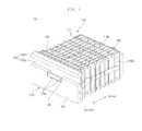
- FIG. 3 is a perspective view illustrating an airtight container of FIG. 1 .
- FIG. 4 is a perspective view illustrating the airtight container, which is opened.
- FIG. 5 is a cross-sectional view taken along line A-A of FIG. 3 , (a) of which shows a ventilation port closed by a withdrawable member, and (b) of which shows the ventilation port opened by the withdrawable member.
- the airtight container 100 may include a case 110, a drawer 120, and a ventilation port opening/closing member 140.
- the case 110 may have a storage space form therein, which is maintained at a negative pressure state.
- the negative pressure state may refer to a lower atmospheric pressure state than an external atmosphere.
- the vacuum pump 190 may be further provided to forcibly discharge air out of the storage space of the case 110.
- a lower air pressure of the storage space may be advantageous for the airtightness of the airtight container 100, but it is difficult to allow the storage space to become a complete vacuum state.
- the drop of the air pressure can cause the transpiration through the stomata of the vegetables to be activated. Structurally, since the stiffness of the case 110 may also be sufficiently secured to endure the drop of the air pressure, it is desirable to maintain the storage space at a weak vacuum state.
- the case 110 may have an opening 113 formed at the front side thereof.
- the drawer 120 may be inserted into the case 110 through the opening 113.
- the case 110 may have a box shape with an opening formed at the front side thereof.
- the case 110 may include a case rear surface (not shown), a case top surface 110a and a case bottom surface 110c extending from the case rear surface and facing each other in a vertical direction, and a pair of case side surfaces 110b facing each other in a horizontal direction.
- the vacuum pump 190 may also be connected to the case 110 through a connection pipe. In this case, air may be discharged through the connection pipe during the operation of the vacuum pump 190.
- the case 110 may have a reinforcing rib 111 protruding from at least one of the case top surface 110a, the case bottom surface 110c, and the case side surface 110b.
- the reinforcing rib 111 may be formed to have a lattice structure, and may be formed integrally with the case 110 through injection molding of synthetic resins.
- the reinforcing member 130 may add a stiffness to prevent the case from being deformed by a negative pressure of the inside of the case 110.
- the reinforcing member 130 may be formed of a material, e.g., a metallic material having a stiffness larger than the case 110, and may be coupled to the case 110 along the circumference of the case 110.
- the reinforcing member 130 may be laterally extended to be coupled to the case top surface 110a, but the present invention is not limited thereto.
- the reinforcing member 130 may also be provided on the side surface 110b or the bottom surface 110c.
- the drawer 120 may receive stored goods, and may open and close the storage space of the case 110.
- the drawer 120 may be straightly-movably supported by the case 110. Since the storage space is maintained at a weak vacuum state, when the drawer 120 closes the case 110, the drawer may be adhered closely to the case 110 due to the negative pressure. Accordingly, the airtightness of the storage space may be maintained.
- a fixing rail 117 may be disposed on the inner side of the case 110 to support the movement of the drawer 120.
- a movement guide 129 may be disposed on the drawer 120 to be supported by the fixing rail 117.
- the drawer 120 may include a receiving part 124 forming a receiving space and an airtight container door 121 disposed at the front side of the receiving part 124.
- the receiving part 124 may have a container shape with the upper side thereof opened, and may hold stored goods therein.
- the airtight container door 121 may include a protrusion bar 122b protruding forward such that a user can grip the protrusion bar 122b.
- the airtight container door 121 may include a door frame 122 and a door panel 123 coupled to the front surface of the door frame 122.
- the door frame 122 may include a cover part 122a having a rear surface covering the opening 113 and a front surface on which the door panel 123 is mounted.
- a sealer (not shown) may be provided on an area of the rear surface of the cover part 122a facing the circumference of the opening 113 of the case 110 to improve airtightness of the storage space by adhering closely to the circumference of the opening 113 when the airtight container door 121 is closed. Since the sealer is formed of a flexible material which can be flexibly deformed like silicone or rubber, the sealer may be deformed according to the drop of the air pressure of the storage space.
- the ventilation port H may be formed in the door frame 122, particularly, cover part 122a, and may be covered by the door panel 122 so as to be invisible from the outside.
- the protrusion bar 122b may forwardly protrude from the upper end of the cover part 122a.
- the ventilation port opening/closing member 140 may ventilate the storage space such that the weak vacuum state inside the storage space of the case 110 can be released, and may straightly move in the same direction as the drawer 120.
- the ventilation port H may be opened/closed according to the movement of the ventilation port opening/closing member 140.
- a ventilation port sealer 150 may be inserted into the ventilation port H.
- the ventilation port sealer 150 may be formed of a flexible (deformable) material, and may have a tubular shape and a slit 151.
- the ventilation port sealer 150 may be formed of silicone or synthetic or natural rubber.
- the ventilation port sealer 150 may have a plurality of portions cut at one end thereof opened toward the storage space.
- the inner diameter of the ventilation port sealer 150 may be slightly smaller than the inner diameter of the sealing protrusion 142.
- the ventilation port sealer 150 may be torn by a shearing force.
- a pre-cut portion 152 may be formed on one end of the ventilation port sealer 150 on which a stress is concentrated, thereby allowing both sides of the pre-cut portion 152 to naturally spread out when the sealing protrusion 142 is inserted into the ventilation port sealer 150.
- the ventilation port opening/closing member 140 may be movably supported by the drawer 120.
- the ventilation port opening/closing member 140 may be supported by any one of the door frame 122 or the door panel 123.
- the door panel 123 is formed of a thin plate, it may be difficult to maintain a steady contact between the door panel 123 and the ventilation port opening/closing member 140 on the movement path of the ventilation port opening/closing member 140 only with the door panel 123. Accordingly, the ventilation port opening/closing member 140 may be supported movably along a guide surface of the door frame 122.
- the ventilation port opening/closing member 140 may include the sealing protrusion 142 that is inserted into the ventilation port H, 151 for the sealing of the storage space.
- the sealing protrusion 142 may be inserted into the ventilation port H, 151 to maintain airtightness of the storage space of the case 110. Also, the sealing protrusion 142 may be withdrawn from the ventilation port H, 151 according to the movement of the ventilation port opening/closing member 140 to release the airtight state of the storage space.
- the ventilation port opening/closing member 140 may include a grip part 141 vertically extending from a location laterally spaced from the sealing protrusion 142.
- the sealing protrusion 142 may be connected to the grip part 141 through a connection part 143 extending in a lateral direction.
- a support protrusion 144 may downwardly protrude from the connection part 143.
- the support protrusion 144 may be moved along and supported by a guide groove 122c formed in the door frame 122 within a rear region of the door panel 123.
- a support protrusion withdrawal hole 123b may be formed in the door panel 123 such that the support protrusion 144 can escape to the front side when the ventilation port opening/closing member 140 is pulled for the opening of the ventilation port H
- the grip part 141 may have a stopping protrusion 141a formed on the rear portion thereof.
- the stopping protrusion 141a may have a curved shape at a contact portion with the finger to allow the finger of a user to be stopped. Since the finger of a user contacts the curved surface of the stopping protrusion 141a, the grip feeling may be improved, and the grip part may be operated with a smaller force due to an increase of the contact area with the finger.
- the elastic member 160 may elastically support the ventilation port opening/closing member 140.
- the elastic member 160 may be elastically deformed when the ventilation port opening/closing member 140 moves and thus the sealing protrusion is withdrawn from the ventilation port H.
- the elastic member 160 may restore the ventilation port opening/closing member 140 to the original location by its own restoring force. Accordingly, even through a user releases his/her grip after pulling the ventilation port H, 151, the ventilation port opening/closing member 140 may be automatically restored to the original location, and the ventilation port H may be sealed by the sealing protrusion 142.
- the elastic member is exemplified as a spring, but the present invention is not limited thereto. For example, anything else that can restore the ventilation port opening/closing member 140 to the original location due to the restoring force accumulated upon its own deformation can be used.
- the process of withdrawing the drawer 120 may include the opening of the ventilation port H, 151 and then the movement of the drawer 120.
- the movement of the ventilation port opening/closing member 140 and the movement of the drawer 120 are performed in the same direction, the release of the weak vacuum and the withdrawal of the drawer 120 can be achieved only with a simple operation of pulling the ventilation port opening/closing member 140 by a user.
- the ventilation port opening/closing member 140 and the drawer 120 may be connected to each other by the elastic member 160.
- the ventilation port opening/closing member 140 When the ventilation port opening/closing member 140 is pulled, the ventilation port H, 151 may be opened together with the deformation of the elastic member 160.
- the drawer 120 When the deformation of the elastic member 160 reaches a certain degree, the drawer 120 may move together with the ventilation port opening/closing member 140.
- a force for pulling the ventilation port opening/closing member 140 is removed after the complete opening of the drawer 120, the ventilation port opening/closing member 140 may be restored to the original location by a restoring force of the elastic member 160 in a state where the drawer 120 is withdrawn, and the ventilation port H may be closed again.
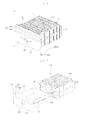
- FIG. 6 is a perspective view illustrating an airtight container according to another embodiment of the present invention.
- FIG. 7 is a perspective view illustrating the airtight container of FIG. 6 , which is opened.
- FIG. 8 is a perspective view illustrating a case according to an embodiment of the present invention.
- FIG. 9 is a cross-sectional view taken along line A-A of FIG. 6 .
- FIG. 10 is a cross-sectional view illustrating a sealing maintaining apparatus of FIG. 9 , which releases sealing.
- an airtight container 100' may include a case 110, a drawer 120'.
- the case 110 defines the external appearance of the airtight container or vegetable container 100'.
- the case 110 is mounted in the storage compartments F and R of the main body 2 of the refrigerator.
- the case 110 is configured to have a double structure including an inner case and an outer case.
- the outer case may be fixed in the storage compartments F and R and the inner case may be mounted in the outer case such that the inner case can be withdrawn from the outer case.
- the case 110 has an opening 113 formed at the front thereof.
- a receiving space A see Fig. 8
- a vacuum pump 190 to generate negative pressure in the case 110 may be mounted at one side of the case 110.
- the vacuum pump 190 may be connected to the case 110 via a connection pipe. When the drawer 120' is inserted into the case 110, therefore, the vacuum pump 190 may discharge air from the case 110 to decompress the case 110.
- a flange 119 extending outside the receiving space A. That is, the flange 119 may be formed at the front of the case 110 such that the flange 119 extends outward.
- the flange 119 may be disposed perpendicularly the top surface 110a and the bottom surface 110b of the case 110 to prevent the edge of the opening 113 from drooping due to negative pressure generated in the case 110.
- the flange 119 may be formed in the vertical direction of the case 110 to function as a bending stress support to resist bending stress generated at the edge of the opening 113.
- the flange 119 provides a region contacting the drawer 120' when the drawer 120' hermetically seals the case 110. Particularly, in a case in which the interior of the case 110 is maintained almost in a vacuum state, it is necessary for the interior of the case 110 to be completely isolated from the outside. Since the flange 119 provides a space which the drawer 120' contacts, the flange 119 improves hermetical sealing performance of the airtight container 100'. In addition, in a case in which a hermetical sealing member 520 is used at a contact area between the drawer 120' and the case 110, the flange 119 may provide a space which the hermetical sealing member 520 contacts.
- At least one surface of the edge of the opening 113 may be configured to have an arch structure in which the middle portion of the surface of the edge of the opening 113 protrudes outside the receiving space A.
- the case 110 may further include a reinforcing rib 111 to increase strength of the case 110.
- the reinforcing rib 111 is a member formed in the direction in which the case 110 is deformed.
- the reinforcing rib 111 may be integrally formed with the case 110 by injection molding.
- the reinforcing rib 111 may be formed at the outer surface of the case 110 to secure the receiving space A in the case 110.
- a plurality of reinforcing ribs 111 may be formed in a first direction and a plurality of reinforcing ribs 111 may be further formed in a direction intersecting the first direction.
- fixed rails 117 In the inner surface of the case 110 may be formed fixed rails 117 to guide the drawer 120' such that the drawer 120' can be inserted into and withdrawn from the case 110 in a drawer fashion.
- the fixed rails 117 may be formed at the inner lateral surfaces of the case 1110 such that the fixed rails 117 extend from the front to the rear.
- the drawer 120' hermetically seals the interior of the case 110.
- the drawer 120' defines the external appearance of the vegetable container 100' together with the case 110.
- the drawer 120' may include a receiving part 124 defining a receiving space to receive objects to be stored and an airtight container door 121 disposed at the front of the receiving part 124.
- the receiving part 124 is inserted into and withdrawn from the case 110 in a drawer fashion.
- moving guides 129 corresponding to the fixed rails 117 of the case 110 are formed at the outer surface of the receiving part 124 such that the receiving part 124 can move forward from the case 110 and backward into the case 110 along the fixed rails 117.
- the airtight container door 121 may be disposed at the front of the receiving part 124.
- the airtight container door 121 may be formed to have a larger size than the receiving part 124. Consequently, the edge of the airtight container door 121 contacts the edge of the opening 113 to hermetically seal the case 110.
- the airtight container door 121 may be formed approximately in the shape of a rectangle (rectangular parallelepiped). More specifically, the airtight container door 121 may have a size and a shape corresponding to the size and the shape of the flange 119 of the opening 113. That is, the airtight container door 121 may be formed so as to contact the flange 119 of the case 110.
- the airtight container door 121 may include a door frame 122 and a door panel 123' coupled to the front surface of the door frame 122.
- the door frame 122 may include a cover part 122a having a rear surface covering the opening 113 and a front surface on which the door panel 123' is mounted.
- a sealer (not shown) may be provided on an area of the rear surface of the cover part 122a facing the circumference of the opening 113 of the case 110 to improve airtightness of the storage space by adhering closely to the circumference of the opening 113 when the airtight container door 121 is closed. Since the sealer is formed of a flexible material which can be flexibly deformed like silicone or rubber, the sealer may be deformed according to the drop of the air pressure of the storage space.
- the difference in pressure between the inside and the outside of the case 110 is generated. That is, when the interior of the case 110 is hermetically sealed by the drawer 120', the interior of the case 110 is decompressed by the vacuum pump 190 with the result that the pressure inside the case 110 becomes lower than the pressure outside the case 110.
- the hermetical sealing member 520 may be provided at a contact region between the airtight container door 121 of the drawer 120' and the edge of the opening 113 to isolate the inside of the case 110 from the outside of the case 110.
- the hermetical sealing member 520 may be made of a rubber material.
- the hermetical sealing member 520 may be formed along the edge (or the flange 119) of the opening 113 in a closed loop shape.
- a hermetical sealing retention device 510 to retain an isolated state of the inside of the case 110 from the outside of the case 110.
- the hermetical sealing retention device 510 may include a catching part coupled to one selected from between the drawer 120' and the case 110 and a fastening part coupled to the other selected from between the drawer 120 and the case 110 such that the fastening part can be fastened to the catching part.
- the present invention is not limited thereto.
- the hermetical sealing retention device 510 may have various structures.
- a ventilation port 127 may be further provided to allow air to flow into and out of the drawer 120'. Also, a sealing maintaining apparatus 300 may be further provided in the drawer 120' to open and close the ventilation port 127.
- the ventilation port 127 may penetrate the drawer 120' to allow external air to flow into and out of the case 110.
- the weak vacuum state inside the case 110 may be released.
- the ventilation port 127 may be formed in the airtight container door 121 of the drawer 120'.
- the sealing maintaining apparatus 300 may be disposed in the drawer 120' to open and close the ventilation port 127 by an external force and an elastic force.
- the sealing maintaining apparatus 300 may be disposed to be exposed to the outside of the drawer 120', or may be embedded in the drawer 120'.
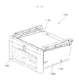
- the airtight container door 121 of the drawer 120' may further include a receiving part 128 for receiving the sealing maintaining apparatus 300 and a receiving part cover 400 for covering the receiving part 128.
- the receiving part may be formed such that a portion of the airtight container door 121 of the drawer 120' is recessed in the direction of the receiving part.
- the receiving part 128 may be formed to have a space of a substantially hexahedral shape, and may be located at the center of the airtight container door 121 of the drawer 120'.
- the receiving part cover 400 may cover the receiving part 128, and may be disposed so as to expose an operation switch 340. That is, the receiving part cover 400 may cover the sealing maintaining apparatus 300 from the outside and may expose only the operation switch 340 in order to improve the esthetic feeling of the exterior of the drawer 120'.
- the sealing maintaining apparatus 300 may include a sealing part 310, a driving arm 320, a compression spring 330, and an operation switch 340.
- the sealing part 310 may seal the ventilation port 127.
- the sealing part 310 may be formed to have a large contact area with the ventilation port 127 so as to seal the ventilation port 127 by adhering closely to the ventilation port 127.
- the sealing part 310 may have a semispherical shape protruding to the ventilation port 127, and the edge of the ventilation port 127 may have a shape corresponding to the sealing part 310.
- the sealing part 310 may be formed of a deformable material in shape to effectively seal the ventilation port 127 when contacting the ventilation port 127.
- the sealing part 310 may include rubber or silicone.
- the driving arm 320 may be rotatably disposed in the drawer 120' to deliver a driving force caused by an external force to the sealing part 310.
- the driving arm 320 may be rotatably disposed on a supporter 530 upwardly protruding from the airtight container door 121 of the drawer 120'.
- the driving arm 320 may include a rotation axis 323 that is rotatably inserted into the supporter 530 at the center thereof.
- One end 321 of the driving arm 320 may be connected to the sealing part 310, and the other end 322 of the driving arm 320 symmetrically disposed about the rotation axis 323 may be supported by the compression spring 330.
- the compression spring 330 may provide the driving arm 320 with an elastic force such that the sealing part 310 seals the ventilation port 127.
- a fixing protrusion 125 may be formed to upwardly protrude from the airtight container door 121 of the drawer 120'.
- One end of the compression spring 330 may be inserted into the fixing protrusion 125 to be fixed.
- a hole may be formed in the other end 322 of the driving arm 320 to fix the other end of the compression spring 330.
- the driving arm 320 may be rotatably disposed about the rotation axis 323, and the sealing part 310 may be connected to the lower side of one end 321 of the driving arm 320.
- the compression spring 330 may be disposed under the other end of the driving arm 320. Accordingly, the driving arm 320 may be rotated by an elastic force of the compression spring 330 to pivot between a sealing location (see FIG. 9 ) at which the sealing part 310 seals the ventilation port 127 and a release location (see FIG. 10 ) at which the sealing part 310 opens the ventilation port 127.
- the external force may denote all forces that overcome the elastic force by the compression spring 330 and move the other end 322 of the driving arm 320 in a downward direction.
- one end 321 of the driving arm 320 may move upward, allowing the sealing part 310 to be spaced from the ventilation port 127.
- the supporter 530 may be formed to protrude from the bottom of the receiving part 128.
- the operation switch 340 may be disposed in the drawer 120', and may allow the driving arm 320 to rotate between the sealing location and the release location. That is, when a user applies an external force to the operation switch 340, the operation switch 340 may deliver the external force to the driving force.
- the operation switch 340 may be disposed over the other end 322 of the driving arm 320, and the compression spring 330 may be disposed under the other end 322 of the driving arm 320. Accordingly, when an external force is applied to the operation switch 340, the external force may exceed the elastic force of the compression spring 330, allowing the other end 322 of the driving arm 320 to move downward and thus allowing the sealing part 310 to be spaced from the ventilation port 127. On the other hand, when the external force is removed, the operation switch 340 may be restored to the initial location by the elastic force of the compression spring 330.
- the operation switch 340 and the compression spring 330 may be vertically and symmetrically disposed about the driving arm 320.
- the operation switch 340 may be disposed in the airtight container door 121 of the drawer so as to be exposed to the outside, and may be disposed so as to reciprocate in a vertical direction.
- a region 510 may be opened.
- the operation switch 340 may be disposed in the region 510 so as to reciprocate in a vertical direction.
- the operation switch 340 may include an operation plate 341 exposed to the outside and disposed on the same plane as the receiving part cover 400, a pushing part 342 downwardly protruding from the operation plate 341 to push the other end 322 of the driving arm 320, and a guide piece 343 downwardly extending from the edge of the operation plate 341 to be guided by an operation switch guide 410 described below.
- the receiving part cover 400 may further include the operation switch guide 410 for guiding the movement of the operation switch 340.
- the operation switch guide 410 may downwardly extend from the edge of a partial region I of the receiving part cover 400 by a certain length.
- the inside of the case 110 may become a weak vacuum state by the vacuum pump 190.
- the operation switch 340 may be located at the initial location by an elastic force of the compression spring 330.
- the other end 322 of the driving arm 320 may be upwardly moved by the elastic force of the compression spring 330, and one end 321 of the driving arm 320 symmetrically disposed about the rotation axis 323 may be downwardly moved to allow the sealing part 310 to seal the ventilation port 127. Accordingly, the inside of the case 110 may be maintained at a weak vacuum state.
- the external force may exceed the elastic force of the compression spring 330, allowing the other end 322 of the driving arm 320 to move downward and allowing one end 321 of the driving arm 320 symmetrically disposed about the rotation axis 323 to move upward.
- the sealing part 310 may open the ventilation port 127. Accordingly, the weak vacuum state inside the case 110 may be released, and a user can easily open the drawer 120'.
- a user can easily release the weak vacuum state inside the case 110 by pressurizing the operation switch 340 before the drawer 120' is opened.
- the inside of the case 110 When the inside of the case 110 is in the weak vacuum state, it may be difficult even for an adult to open the drawer 120' due to a pressure difference between the inside and the outside of the case 110. However, in this embodiment, since the weak vacuum state of the inside of the case 110 can be released by the sealing maintaining apparatus 300, a user can easily open the drawer 120'.
- the ventilation port opening/closing member ventilating the airtight container of the refrigerator and the drawer move in the same direction, the ventilation port opening/closing member and the drawer can be moved by a force applied on the same line. Accordingly, the present invention has an effect in that the drawer can be together withdrawn with a force applied for the operation of the ventilation port opening/closing member.
- the present invention has an effect in that the edge of an opening of a case is designed to have an arch structure to prevent the circumference of the opening of the case from being bent inside the case.
- the present invention has an effect in that a flange is formed at the edge of the opening to prevent the edge of the opening from drooping and to provide a contact surface between a hermetical sealing member and a drawer.
- the present invention has an effect in that a reinforcing member is coupled adjacent to the edge of the opening to reduce deformation of the edge of the opening.
- the present invention has an effect in that deformation of the edge of the opening is restrained, whereby it is possible to continuously maintain the interior of a vegetable container in a low vacuum state.
- the present invention has an effect in that the discharge port is hermetically sealed by the opening and closing valve due to external force of an elastic spring at a normal time, whereby the interior of the case is maintained in a low vacuum state and, when the drawer is opened, the opening and closing valve is automatically opened to discharge water formed in the case to the outside
- the present invention has an effect in that a user can easily release the weak vacuum state of the inside of the case by pressurizing the operation switch before the drawer is opened.
- the present invention has an effect in that the drawer can be easily opened with a simple configuration.
Abstract
Description
- This application claims the priority benefit of Korean Patent Application No
.10-2013-0060553, filed on May 28, 2013 10-2013-0060554 filed on May 28, 2013 - The present invention relates to an airtight container for a refrigerator and a refrigerator including the airtight container, and more particularly, to an airtight container for a refrigerator and a refrigerator including the airtight container, which can be easily opened even when the airtight container is in a weak vacuum state.
- Generally, a refrigerator is an apparatus that supplies chill generated through a freezing cycle into the storage compartments and lowers the temperature of the inside of the storage compartments to maintain the freshness of various foods for a longtime.
- Recently, the refrigerator is equipped with a separate storage compartment optimized for the characteristics of foods in addition to typical refrigeration compartment and freezer compartment. For example, an airtight container is provided to maintain the optimal freshness of vegetables for a longtime.
- A typical airtight container includes a case supplied with chill and a drawer withdrawably disposed in the case and storing vegetables. In order to maintain the freshness of vegetables, when the drawer is in an insertion state into the case (i.e., when airtight container is in a closed state), the airtightness of the airtight container has to be maintained. To this end, a vacuum pump may be further provided to maintain the inside of the airtight container at a weak vacuum state. In this case, a user needs to release the weak vacuum state of the airtight container to take vegetables out of the airtight container.
- In a related art, a ventilation port is provided in the drawer to communicate between the inside and the outside of the airtight container, and an operation handle is provided to control the ventilation port by a user. However, in this structure, since the directions of the operation of the operation handle and the movement of the drawer are different from each other, there is a limitation in that the drawer has to be withdrawn in a straight-line direction after the weak vacuum state inside the airtight container is released by rotating the operation handle to take vegetables out of the airtight container.
-
FIG. 11 is a perspective view showing a conventional airtight container orvegetable container 1000 for refrigerators. Theconventional vegetable container 1000 includes acase 1100 and adrawer 1300. - In a case in which the
conventional vegetable container 1000 is configured to have a two-box type structure, thedrawer 1300 is inserted into thecase 1100 in a drawer fashion. As a result, the interior of thevegetable container 1000 is hermetically sealed such that the interior of thevegetable container 1000 is in a low vacuum state to improve freshness of the vegetables stored in thevegetable container 1000. - In the conventional two-box type structure, the
drawer 1300 hermetically seals the interior of thevegetable container 1000 such that foods can be stored in thevegetable container 1000 in a fresh state for a long period of time. Conventionally, a vacuum pump is mounted in thehermetical sealing drawer 1300 or thevegetable container 1000 to uniformly maintain vacuum in thevegetable container 1000 such that foods can be stored in thevegetable container 1000 in a fresh state for a long period of time. - In this case, however, an opening of the
case 1100, through which thedrawer 1300 is inserted into thecase 1100, may be deformed toward the interior of thecase 1100 due to the difference in pressure between the inside and the outside of thecase 1100. - In a case in which the
case 1100 is deformed, hermetical sealing between thedrawer 1300 and thecase 1100 may be released with the result that external air may be introduced into thecase 1100 and, therefore, the low vacuum state in thecase 1100 may be released. - In addition, when temperature in the
case 1100 is lowered, dew may be formed in thecase 1100. - The dew formed in the
case 1100 may stay on the inner surface of thecase 1100 with the result that the dew may be observed by the naked eye. - Furthermore, in a case in which the dew formed in the
case 1100 drops and contacts foods stored in thevegetable container 1000, the food may be softened. - In addition, the dew formed in the
case 1100 may not be discharged out of thecase 1100. - Furthermore, when the inside of the
case 1100 becomes a weak vacuum state, even an adult may not easily open thedrawer 1300 due to a pressure difference between the inside and the outside of thecase 1100. - The present invention provides an airtight container for a refrigerator and a refrigerator including the airtight container, which can be easily opened even when the airtight container is in a weak vacuum state.
- The present invention also provides an airtight container for a refrigerator and a refrigerator including the airtight container, which can be maintained the inside of the airtight container at a weak vacuum state.
- The present invention also provides an airtight container for a refrigerator and a refrigerator including the airtight container, which prevents a user from observing dew generated in the airtight container for the refrigerator with the naked eyes and guides dew into a water collection part.
- The present invention also provides an airtight container for a refrigerator and a refrigerator including the airtight container, which can simply discharge dew generated inside the airtight container.
- According to an aspect of the present invention, there is provided a refrigerator comprising: a case having a storage space formed therein and maintained at a negative pressure state; a drawer storing food and opening and closing the storage space while being supported by the case so as to move in a straight line; and a ventilation port opening/closing member ventilating the storage space, wherein the drawer comprises a ventilation port for ventilating the storage space, and the ventilation port opening/closing member straightly moves in the same direction as the drawer to open and close the ventilation port.
- In one embodiment, the ventilation port opening/closing member may be movably supported by the drawer.
- In one embodiment, after the ventilation port is opened, the drawer may move together with the ventilation port opening/closing member by a force acting on the ventilation port opening/closing member.
- In one embodiment, the ventilation port opening/closing member may include a sealing protrusion that is inserted into the ventilation port to seal the storage space, and the sealing protrusion may be withdrawn from the ventilation port according to a movement of the ventilation port opening/closing member.
- In one embodiment, the refrigerator may further include an elastic member that elastically supports the ventilation port opening/closing member.
- In one embodiment, the elastic member may be elastically deformed when the ventilation port opening/closing member is moved by an external force and the sealing protrusion is withdrawn from the ventilation port, and when the external force applied to the ventilation port opening/closing member is removed, the ventilation port opening/closing member may be restored to an original location by a restoring force of the elastic member.
- In one embodiment, the elastic member may connect the ventilation port opening/closing member and the drawer.
- In one embodiment, the case may have an opening. The drawer may include: a receiving part forming a receiving space for stored goods and inserted into the opening to be supported; and an airtight container door disposed at a front side of the receiving part to open and close the opening. The airtight container door may include: a door frame having a rear surface covering the opening; and a door panel coupled to a front surface of the door frame. The ventilation port may be formed in the door frame. The sealing protrusion may be moved at a rear side of the door panel and may be covered by the door panel so as not to be exposed to the outside.
- In one embodiment, the refrigerator may further include a sealer formed of a flexible material and having a tubular shape inserted into the ventilation port. Here, the sealing protrusion is inserted into the sealer.
- In one embodiment, the sealer may have one end facing the storage space and cut at a plurality of portions thereof.
- In one embodiment, the ventilation port opening/closing member may include: a grip part vertically extending from a location laterally spaced from the sealing protrusion; and a connection part connecting the sealing part and the grip part in a lateral direction.
- In one embodiment, the grip part may include a stopping protrusion formed on a rear portion thereof and having a curved shape at a contact portion with a finger to allow the finger of a user to be stopped.
- In one embodiment, the ventilation port opening/closing member may include a support protrusion protruding downward, and the drawer may have a guide groove formed to support the support protrusion and guide a movement of the support protrusion.
- In one embodiment, when the ventilation port opening/closing member is pulled, the ventilation port opening/closing member may be moved independently of the drawer to open the ventilation port, and when the ventilation port opening/closing member is continuously pulled in a state where the ventilation port is opened, the drawer may be moved together with the ventilation port opening/closing member.
- In one embodiment, the case may have a discharge port formed through a bottom surface of the case such that water collected in the case is discharged out of the case, and may include an opening/closing valve opening the discharge port when an external force is applied and closing the discharge port by being restored to an original location by an elastic force when the external force is removed.
- In one embodiment, the refrigerator may further include a guide channel formed in an inner surface of the case to guide water collected in the case to the discharge port.
- In one embodiment, the guide channel may include at least two mountain parts protruding toward the inside of the case and at least one valley part disposed between the respective mountain parts and depressed toward the outside of the case.
- In one embodiment, the bottom surface of the case may be downwardly inclined toward the discharge port.
- In one embodiment, the refrigerator may further include a reinforcing part for reinforcing a strength of the case. Here, the reinforcing part may be coupled to the case at a location adjacent to the opening of the case which the drawer is inserted into and may include a reinforcing member having a strength larger than the case.
- In one embodiment, the refrigerator may further include a vacuum pump generating a negative pressure in the case.
- The above and other objects, features and other advantages of the present invention will be more clearly understood from the following detailed description taken in conjunction with the accompanying drawings, in which:
-
FIG. 1 is a perspective view of a refrigerator according to an embodiment of the present invention; -
FIG. 2 is a front view illustrating the refrigerator ofFIG. 1 , a door of which is opened; -
FIG. 3 is a perspective view illustrating an airtight container ofFIG. 1 ; -
FIG. 4 is a perspective view illustrating the airtight container, which is opened; -
FIG. 5 is a cross-sectional view taken along line A-A ofFIG. 3 , (a) of which shows a ventilation port closed by a withdrawable member, and (b) of which shows the ventilation port opened by the withdrawable member; -
FIG. 6 is a perspective view illustrating an airtight container according to another embodiment of the present invention; -
FIG. 7 is a perspective view illustrating the airtight container ofFIG. 6 , which is opened; -
FIG. 8 is a perspective view illustrating a case according to an embodiment of the present invention; -
FIG. 9 is a cross-sectional view taken along line A-A ofFIG. 6 ; -
FIG. 10 is a cross-sectional view illustrating a sealing maintaining apparatus ofFIG. 9 , which releases sealing; -
FIG. 11 is a perspective view illustrating a typical airtight container for a refrigerator. - Advantages and features of the present invention and a method of achieving the same will be more clearly understood from embodiments described below with reference to the accompanying drawings. However, the present invention is not limited to the following embodiments but may be implemented in various different forms. The embodiments are provided merely to complete disclosure of the present invention and to fully provide a person having ordinary skill in the art to which the present invention pertains with the category of the invention. The invention is defined only by the category of the claims. Wherever possible, the same reference numbers will be used throughout the specification to refer to the same or like parts.
- Spatially relative terms such as "below," "beneath," "lower," "above," or "upper" may be used herein to describe one element's relationship to another element as illustrated in the drawings. It will be understood that spatially relative terms are intended to encompass different orientations of the elements during use or operation of the elements in addition to the orientation depicted in the drawings. For example, if the elements in one of the drawings are turned over, elements described as "below" or "beneath" other elements would then be oriented "above" the other elements. The exemplary terms "below" or "beneath" can, therefore, encompass both an orientation of above and below. Since the elements may be oriented in another direction, the spatially relative terms may be interpreted in accordance with the orientation of the elements.
- The terminology used in this specification is for the purpose of describing particular embodiments only and is not intended to limit the present invention. As used in this specification, the singular forms are intended to include the plural forms as well unless context clearly indicates otherwise. It will be further understood that the terms "comprises" and/or "comprising, " when used in this specification, specify the presence of stated elements, steps, and/or operations, but do not preclude the presence or addition of one or more other elements, steps, and/or operations.
- Unless otherwise defined, all terms (including technical and scientific terms) used in this specification have the same meaning as commonly understood by a person having ordinary skill in the art to which the present invention pertains. It will be further understood that terms, such as those defined in commonly used dictionaries, should be interpreted as having a meaning that is consistent with their meaning in the context of the relevant art and the present disclosure, and will not be interpreted in an idealized or overly formal sense unless expressly so defined herein.
- In the drawings, the thickness or size of each element is exaggerated, omitted, or schematically illustrated for convenience of description and clarity. Also, the size or area of each element does not entirely reflect the actual size thereof.
- In addition, angles or directions used to describe the structures of embodiments of the present invention are based on those shown in the drawings. Unless there is, in this specification, no definition of a reference point to describe angular positional relations in the structures of embodiments of the present invention, the associated drawings may be referred to.
-
FIG. 1 is a perspective view of a refrigerator according to an embodiment of the present invention.FIG. 2 is a front view illustrating the refrigerator ofFIG. 1 , a door of which is opened. - Referring to
FIGS. 1 and2 , a refrigerator according to an embodiment of the present invention may include amain body 2 providing a storage compartment divided into a freezer compartment F and a refrigeration compartment R anddoors - A cooling
device 48 may supply chill into the storage compartments F and R. In thecooling device 48, refrigerant may circulate along a refrigerant pipe. Thecooling device 48 may provide a circulation cycle of compression, expansion, evaporation, and condensation of refrigerant. During the evaporation of refrigerant among the circulation cycle, ambient air may be cooled. Thecooling device 48 may include a compressor, a condenser, an expander, and an evaporator. In one embodiment, thecooling device 48 may include a thermoelectric module. - The evaporator of the
cooling device 48 may contact the outer wall of the storage compartments F and R to directly cool the storage compartments F and R. Thecooling device 48 may include afan 50 that forcibly convects chill into the storage compartments F and R. In this embodiment, thefan 50 may be provided in the freezer compartment F, but the present invention is not limited thereto. - A plurality of
racks 8 and 10 on which stored goods such as food materials and side dishes may be disposed in themain body 2 to divide the inside of the storage compartments F and R. - A pair of
doors main body 2 to open and close the freezer compartment F and the refrigeration compartment R, respectively. Abasket 5 may be provided at the rear side of thedoors basket 5 may also be provided at thefreezer compartment door 4 to receive frozen goods such as frozen desserts, or may also be provided at therefrigeration compartment door 6 to receive drinks such as milk, juice, and liquor. - A
control panel 60 including a display unit for displaying the operation state of the refrigerator and an input unit for receiving various control commands from a user may be disposed in thedoors - An
airtight container 100 may be provided in the main body to store goods that particularly require moisturization for maintenance of freshness. Theairtight container 100 may have a sealed structure that prevents moisture generated from goods stored therein from leaking to the outside. For sufficient airtightness, the inside of theairtight container 100 may be maintained at a negative pressure state. In order to maintain the inside of theairtight container 100 at a weak vacuum state, a vacuum pump (see 190 ofFIG. 3 ) may be further provided to forcibly discharge air out of theairtight container 100. Generally, since vegetables and fruits in which transpiration occurs through the stomata during a longtime storage are stored in theairtight container 100, theairtight container 100 may also be called a vegetable container. -
FIG. 3 is a perspective view illustrating an airtight container ofFIG. 1 .FIG. 4 is a perspective view illustrating the airtight container, which is opened.FIG. 5 is a cross-sectional view taken along line A-A ofFIG. 3 , (a) of which shows a ventilation port closed by a withdrawable member, and (b) of which shows the ventilation port opened by the withdrawable member. - Referring to
FIGS. 3 to 5 , theairtight container 100 may include acase 110, adrawer 120, and a ventilation port opening/closingmember 140. - The
case 110 may have a storage space form therein, which is maintained at a negative pressure state. Here, the negative pressure state may refer to a lower atmospheric pressure state than an external atmosphere. As described above, thevacuum pump 190 may be further provided to forcibly discharge air out of the storage space of thecase 110. A lower air pressure of the storage space may be advantageous for the airtightness of theairtight container 100, but it is difficult to allow the storage space to become a complete vacuum state. Also, there is a limitation in that the drop of the air pressure can cause the transpiration through the stomata of the vegetables to be activated. Structurally, since the stiffness of thecase 110 may also be sufficiently secured to endure the drop of the air pressure, it is desirable to maintain the storage space at a weak vacuum state. - More specifically, the
case 110 may have anopening 113 formed at the front side thereof. Thedrawer 120 may be inserted into thecase 110 through theopening 113. Thecase 110 may have a box shape with an opening formed at the front side thereof. Thecase 110 may include a case rear surface (not shown), a casetop surface 110a and a casebottom surface 110c extending from the case rear surface and facing each other in a vertical direction, and a pair of case side surfaces 110b facing each other in a horizontal direction. - On the other hand, although not shown, the
vacuum pump 190 may also be connected to thecase 110 through a connection pipe. In this case, air may be discharged through the connection pipe during the operation of thevacuum pump 190. - For the reinforcement of stiffness, the
case 110 may have a reinforcingrib 111 protruding from at least one of the casetop surface 110a, the casebottom surface 110c, and thecase side surface 110b. The reinforcingrib 111 may be formed to have a lattice structure, and may be formed integrally with thecase 110 through injection molding of synthetic resins. - The reinforcing
member 130 may add a stiffness to prevent the case from being deformed by a negative pressure of the inside of thecase 110. The reinforcingmember 130 may be formed of a material, e.g., a metallic material having a stiffness larger than thecase 110, and may be coupled to thecase 110 along the circumference of thecase 110. In this embodiment, the reinforcingmember 130 may be laterally extended to be coupled to the casetop surface 110a, but the present invention is not limited thereto. For example, the reinforcingmember 130 may also be provided on theside surface 110b or thebottom surface 110c. - The
drawer 120 may receive stored goods, and may open and close the storage space of thecase 110. Thedrawer 120 may be straightly-movably supported by thecase 110. Since the storage space is maintained at a weak vacuum state, when thedrawer 120 closes thecase 110, the drawer may be adhered closely to thecase 110 due to the negative pressure. Accordingly, the airtightness of the storage space may be maintained. - A fixing
rail 117 may be disposed on the inner side of thecase 110 to support the movement of thedrawer 120. Amovement guide 129 may be disposed on thedrawer 120 to be supported by the fixingrail 117. - The
drawer 120 may include a receivingpart 124 forming a receiving space and anairtight container door 121 disposed at the front side of the receivingpart 124. The receivingpart 124 may have a container shape with the upper side thereof opened, and may hold stored goods therein. Theairtight container door 121 may include aprotrusion bar 122b protruding forward such that a user can grip theprotrusion bar 122b. - More specifically, the
airtight container door 121 may include adoor frame 122 and adoor panel 123 coupled to the front surface of thedoor frame 122. Thedoor frame 122 may include acover part 122a having a rear surface covering theopening 113 and a front surface on which thedoor panel 123 is mounted. A sealer (not shown) may be provided on an area of the rear surface of thecover part 122a facing the circumference of theopening 113 of thecase 110 to improve airtightness of the storage space by adhering closely to the circumference of theopening 113 when theairtight container door 121 is closed. Since the sealer is formed of a flexible material which can be flexibly deformed like silicone or rubber, the sealer may be deformed according to the drop of the air pressure of the storage space. - The ventilation port H may be formed in the
door frame 122, particularly, coverpart 122a, and may be covered by thedoor panel 122 so as to be invisible from the outside. Theprotrusion bar 122b may forwardly protrude from the upper end of thecover part 122a. - The ventilation port opening/closing
member 140 may ventilate the storage space such that the weak vacuum state inside the storage space of thecase 110 can be released, and may straightly move in the same direction as thedrawer 120. The ventilation port H may be opened/closed according to the movement of the ventilation port opening/closingmember 140. - A
ventilation port sealer 150 may be inserted into the ventilation port H. Theventilation port sealer 150 may be formed of a flexible (deformable) material, and may have a tubular shape and aslit 151. - Even though the
ventilation port sealer 150 is inserted into the ventilation port H, ventilation may be still performed through theslit 151. Accordingly, the meaning of opening or closing the ventilation port H should be construed as opening or closing theslit 151 of theventilation port sealer 150 when theventilation port sealer 150 is installed. Theventilation port sealer 150 may be formed of silicone or synthetic or natural rubber. - The
ventilation port sealer 150 may have a plurality of portions cut at one end thereof opened toward the storage space. For the improvement of airtightness, the inner diameter of theventilation port sealer 150 may be slightly smaller than the inner diameter of the sealingprotrusion 142. In this case, when there is nocut portion 152 152 at one end of theventilation port sealer 150, theventilation port sealer 150 may be torn by a shearing force. Accordingly, in order to overcome this limitation, apre-cut portion 152 may be formed on one end of theventilation port sealer 150 on which a stress is concentrated, thereby allowing both sides of thepre-cut portion 152 to naturally spread out when the sealingprotrusion 142 is inserted into theventilation port sealer 150. - The ventilation port opening/closing
member 140 may be movably supported by thedrawer 120. In this case, the ventilation port opening/closingmember 140 may be supported by any one of thedoor frame 122 or thedoor panel 123. However, in a structure in which thedoor panel 123 is formed of a thin plate, it may be difficult to maintain a steady contact between thedoor panel 123 and the ventilation port opening/closingmember 140 on the movement path of the ventilation port opening/closingmember 140 only with thedoor panel 123. Accordingly, the ventilation port opening/closingmember 140 may be supported movably along a guide surface of thedoor frame 122. In a state where the ventilation port H is opened, since a deflection may occur at the front end corresponding to a distance by which the ventilation port opening/closingmember 140 is pulled, supporting may also be needed at theupper end 123a of thedoor panel 123. - The ventilation port opening/closing
member 140 may include the sealingprotrusion 142 that is inserted into the ventilation port H, 151 for the sealing of the storage space. The sealingprotrusion 142 may be inserted into the ventilation port H, 151 to maintain airtightness of the storage space of thecase 110. Also, the sealingprotrusion 142 may be withdrawn from the ventilation port H, 151 according to the movement of the ventilation port opening/closingmember 140 to release the airtight state of the storage space. - Also, the ventilation port opening/closing
member 140 may include agrip part 141 vertically extending from a location laterally spaced from the sealingprotrusion 142. The sealingprotrusion 142 may be connected to thegrip part 141 through aconnection part 143 extending in a lateral direction. - A
support protrusion 144 may downwardly protrude from theconnection part 143. Thesupport protrusion 144 may be moved along and supported by aguide groove 122c formed in thedoor frame 122 within a rear region of thedoor panel 123. A supportprotrusion withdrawal hole 123b may be formed in thedoor panel 123 such that thesupport protrusion 144 can escape to the front side when the ventilation port opening/closingmember 140 is pulled for the opening of the ventilation port H - The
grip part 141 may have a stoppingprotrusion 141a formed on the rear portion thereof. The stoppingprotrusion 141a may have a curved shape at a contact portion with the finger to allow the finger of a user to be stopped. Since the finger of a user contacts the curved surface of the stoppingprotrusion 141a, the grip feeling may be improved, and the grip part may be operated with a smaller force due to an increase of the contact area with the finger. - The
elastic member 160 may elastically support the ventilation port opening/closingmember 140. Theelastic member 160 may be elastically deformed when the ventilation port opening/closingmember 140 moves and thus the sealing protrusion is withdrawn from the ventilation port H. When an external force applied to the ventilation port opening/closingmember 140 is removed, theelastic member 160 may restore the ventilation port opening/closingmember 140 to the original location by its own restoring force. Accordingly, even through a user releases his/her grip after pulling the ventilation port H, 151, the ventilation port opening/closingmember 140 may be automatically restored to the original location, and the ventilation port H may be sealed by the sealingprotrusion 142. In this embodiment, the elastic member is exemplified as a spring, but the present invention is not limited thereto. For example, anything else that can restore the ventilation port opening/closingmember 140 to the original location due to the restoring force accumulated upon its own deformation can be used. - On the other hand, the process of withdrawing the
drawer 120 may include the opening of the ventilation port H, 151 and then the movement of thedrawer 120. In this process, since the movement of the ventilation port opening/closingmember 140 and the movement of thedrawer 120 are performed in the same direction, the release of the weak vacuum and the withdrawal of thedrawer 120 can be achieved only with a simple operation of pulling the ventilation port opening/closingmember 140 by a user. - The ventilation port opening/closing
member 140 and thedrawer 120 may be connected to each other by theelastic member 160. When the ventilation port opening/closingmember 140 is pulled, the ventilation port H, 151 may be opened together with the deformation of theelastic member 160. When the deformation of theelastic member 160 reaches a certain degree, thedrawer 120 may move together with the ventilation port opening/closingmember 140. When a force for pulling the ventilation port opening/closingmember 140 is removed after the complete opening of thedrawer 120, the ventilation port opening/closingmember 140 may be restored to the original location by a restoring force of theelastic member 160 in a state where thedrawer 120 is withdrawn, and the ventilation port H may be closed again. -
FIG. 6 is a perspective view illustrating an airtight container according to another embodiment of the present invention.FIG. 7 is a perspective view illustrating the airtight container ofFIG. 6 , which is opened.FIG. 8 is a perspective view illustrating a case according to an embodiment of the present invention.FIG. 9 is a cross-sectional view taken along line A-A ofFIG. 6 .FIG. 10 is a cross-sectional view illustrating a sealing maintaining apparatus ofFIG. 9 , which releases sealing. - Referring to
FIGS. 1 , and6 to 8 , an airtight container 100' according to another embodiment of the present invention may include acase 110, a drawer 120'. - The
case 110 defines the external appearance of the airtight container or vegetable container 100'. Thecase 110 is mounted in the storage compartments F and R of themain body 2 of the refrigerator. In addition, thecase 110 is configured to have a double structure including an inner case and an outer case. The outer case may be fixed in the storage compartments F and R and the inner case may be mounted in the outer case such that the inner case can be withdrawn from the outer case. Thecase 110 has anopening 113 formed at the front thereof. In thecase 110 is defined a receiving space A (seeFig. 8 ) to store objects to be stored. - A
vacuum pump 190 to generate negative pressure in thecase 110 may be mounted at one side of thecase 110. - In addition, although not shown, the
vacuum pump 190 may be connected to thecase 110 via a connection pipe. When the drawer 120' is inserted into thecase 110, therefore, thevacuum pump 190 may discharge air from thecase 110 to decompress thecase 110. - At the edge of the
opening 113 may be further formed aflange 119 extending outside the receiving space A. That is, theflange 119 may be formed at the front of thecase 110 such that theflange 119 extends outward. - The
flange 119 may be disposed perpendicularly thetop surface 110a and thebottom surface 110b of thecase 110 to prevent the edge of theopening 113 from drooping due to negative pressure generated in thecase 110. Specifically, theflange 119 may be formed in the vertical direction of thecase 110 to function as a bending stress support to resist bending stress generated at the edge of theopening 113. - In addition, the
flange 119 provides a region contacting the drawer 120' when the drawer 120' hermetically seals thecase 110. Particularly, in a case in which the interior of thecase 110 is maintained almost in a vacuum state, it is necessary for the interior of thecase 110 to be completely isolated from the outside. Since theflange 119 provides a space which the drawer 120' contacts, theflange 119 improves hermetical sealing performance of the airtight container 100'. In addition, in a case in which ahermetical sealing member 520 is used at a contact area between the drawer 120' and thecase 110, theflange 119 may provide a space which thehermetical sealing member 520 contacts. - At least one surface of the edge of the
opening 113 may be configured to have an arch structure in which the middle portion of the surface of the edge of theopening 113 protrudes outside the receiving space A. - That is, in a case in which the edge of the
opening 113 is designed to have an arch structure, it is possible to prevent the circumference of theopening 113 of thecase 110 from being bent inside thecase 110. - The
case 110 may further include a reinforcingrib 111 to increase strength of thecase 110. The reinforcingrib 111 is a member formed in the direction in which thecase 110 is deformed. The reinforcingrib 111 may be integrally formed with thecase 110 by injection molding. - For example, the reinforcing
rib 111 may be formed at the outer surface of thecase 110 to secure the receiving space A in thecase 110. In addition, a plurality of reinforcingribs 111 may be formed in a first direction and a plurality of reinforcingribs 111 may be further formed in a direction intersecting the first direction. - In the inner surface of the
case 110 may be formed fixedrails 117 to guide the drawer 120' such that the drawer 120' can be inserted into and withdrawn from thecase 110 in a drawer fashion. For example, the fixedrails 117 may be formed at the inner lateral surfaces of the case 1110 such that the fixedrails 117 extend from the front to the rear. - The drawer 120' hermetically seals the interior of the
case 110. The drawer 120' defines the external appearance of the vegetable container 100' together with thecase 110. - For example, the drawer 120' may include a receiving
part 124 defining a receiving space to receive objects to be stored and anairtight container door 121 disposed at the front of the receivingpart 124. - The receiving
part 124 is inserted into and withdrawn from thecase 110 in a drawer fashion. For example, movingguides 129 corresponding to the fixedrails 117 of thecase 110 are formed at the outer surface of the receivingpart 124 such that the receivingpart 124 can move forward from thecase 110 and backward into thecase 110 along the fixed rails 117. - The
airtight container door 121 may be disposed at the front of the receivingpart 124. Theairtight container door 121 may be formed to have a larger size than the receivingpart 124. Consequently, the edge of theairtight container door 121 contacts the edge of theopening 113 to hermetically seal thecase 110. - The
airtight container door 121 may be formed approximately in the shape of a rectangle (rectangular parallelepiped). More specifically, theairtight container door 121 may have a size and a shape corresponding to the size and the shape of theflange 119 of theopening 113. That is, theairtight container door 121 may be formed so as to contact theflange 119 of thecase 110. - The
airtight container door 121 may include adoor frame 122 and a door panel 123' coupled to the front surface of thedoor frame 122. Thedoor frame 122 may include acover part 122a having a rear surface covering theopening 113 and a front surface on which the door panel 123' is mounted. A sealer (not shown) may be provided on an area of the rear surface of thecover part 122a facing the circumference of theopening 113 of thecase 110 to improve airtightness of the storage space by adhering closely to the circumference of theopening 113 when theairtight container door 121 is closed. Since the sealer is formed of a flexible material which can be flexibly deformed like silicone or rubber, the sealer may be deformed according to the drop of the air pressure of the storage space. - In a case in which the interior of the
case 110 is hermetically sealed by the drawer 120', the difference in pressure between the inside and the outside of thecase 110 is generated. That is, when the interior of thecase 110 is hermetically sealed by the drawer 120', the interior of thecase 110 is decompressed by thevacuum pump 190 with the result that the pressure inside thecase 110 becomes lower than the pressure outside thecase 110. - The
hermetical sealing member 520 may be provided at a contact region between theairtight container door 121 of the drawer 120' and the edge of theopening 113 to isolate the inside of thecase 110 from the outside of thecase 110. For example, thehermetical sealing member 520 may be made of a rubber material. - The
hermetical sealing member 520 may be formed along the edge (or the flange 119) of theopening 113 in a closed loop shape. - Between the
case 110 and the drawer 120' may be provided a hermeticalsealing retention device 510 to retain an isolated state of the inside of thecase 110 from the outside of thecase 110. - For example, the hermetical
sealing retention device 510 may include a catching part coupled to one selected from between the drawer 120' and thecase 110 and a fastening part coupled to the other selected from between thedrawer 120 and thecase 110 such that the fastening part can be fastened to the catching part. However, the present invention is not limited thereto. The hermeticalsealing retention device 510 may have various structures. - Referring to
FIGS. 9 and 10 , aventilation port 127 may be further provided to allow air to flow into and out of the drawer 120'. Also, asealing maintaining apparatus 300 may be further provided in the drawer 120' to open and close theventilation port 127. - The
ventilation port 127 may penetrate the drawer 120' to allow external air to flow into and out of thecase 110. When external air flows into thecase 110 through theventilation port 127, the weak vacuum state inside thecase 110 may be released. - For example, the
ventilation port 127 may be formed in theairtight container door 121 of the drawer 120'. - The
sealing maintaining apparatus 300 may be disposed in the drawer 120' to open and close theventilation port 127 by an external force and an elastic force. - The
sealing maintaining apparatus 300 may be disposed to be exposed to the outside of the drawer 120', or may be embedded in the drawer 120'. - Specifically, as shown in
FIG. 9 , theairtight container door 121 of the drawer 120' may further include a receivingpart 128 for receiving thesealing maintaining apparatus 300 and a receivingpart cover 400 for covering the receivingpart 128. - The receiving part may be formed such that a portion of the
airtight container door 121 of the drawer 120' is recessed in the direction of the receiving part. The receivingpart 128 may be formed to have a space of a substantially hexahedral shape, and may be located at the center of theairtight container door 121 of the drawer 120'. - The receiving
part cover 400 may cover the receivingpart 128, and may be disposed so as to expose anoperation switch 340. That is, the receivingpart cover 400 may cover thesealing maintaining apparatus 300 from the outside and may expose only theoperation switch 340 in order to improve the esthetic feeling of the exterior of the drawer 120'. - For example, the
sealing maintaining apparatus 300 may include a sealingpart 310, a drivingarm 320, acompression spring 330, and anoperation switch 340. - The sealing
part 310 may seal theventilation port 127. The sealingpart 310 may be formed to have a large contact area with theventilation port 127 so as to seal theventilation port 127 by adhering closely to theventilation port 127. - Specifically, the sealing
part 310 may have a semispherical shape protruding to theventilation port 127, and the edge of theventilation port 127 may have a shape corresponding to the sealingpart 310. - The sealing
part 310 may be formed of a deformable material in shape to effectively seal theventilation port 127 when contacting theventilation port 127. For example, the sealingpart 310 may include rubber or silicone. - The driving
arm 320 may be rotatably disposed in the drawer 120' to deliver a driving force caused by an external force to the sealingpart 310. - Specifically, in order to provide a space in which the
driving arm 320 is rotatable, the drivingarm 320 may be rotatably disposed on asupporter 530 upwardly protruding from theairtight container door 121 of the drawer 120'. - For example, the driving
arm 320 may include arotation axis 323 that is rotatably inserted into thesupporter 530 at the center thereof. Oneend 321 of the drivingarm 320 may be connected to the sealingpart 310, and theother end 322 of the drivingarm 320 symmetrically disposed about therotation axis 323 may be supported by thecompression spring 330. - The
compression spring 330 may provide thedriving arm 320 with an elastic force such that the sealingpart 310 seals theventilation port 127. - In order to fix the location of the
compression spring 330, a fixingprotrusion 125 may be formed to upwardly protrude from theairtight container door 121 of the drawer 120'. One end of thecompression spring 330 may be inserted into the fixingprotrusion 125 to be fixed. Also, a hole may be formed in theother end 322 of the drivingarm 320 to fix the other end of thecompression spring 330. - In other words, the driving
arm 320 may be rotatably disposed about therotation axis 323, and the sealingpart 310 may be connected to the lower side of oneend 321 of the drivingarm 320. Also, thecompression spring 330 may be disposed under the other end of the drivingarm 320. Accordingly, the drivingarm 320 may be rotated by an elastic force of thecompression spring 330 to pivot between a sealing location (seeFIG. 9 ) at which the sealingpart 310 seals theventilation port 127 and a release location (seeFIG. 10 ) at which the sealingpart 310 opens theventilation port 127. - Here, the external force may denote all forces that overcome the elastic force by the
compression spring 330 and move theother end 322 of the drivingarm 320 in a downward direction. - When the
other end 322 of the drivingarm 320 moves downward, oneend 321 of the drivingarm 320 symmetrically disposed about therotation axis 323 may move upward, allowing the sealingpart 310 to be spaced from theventilation port 127. - In this case, when the
sealing maintaining apparatus 300 is accommodated in the receivingpart 128, thesupporter 530 may be formed to protrude from the bottom of the receivingpart 128. - The
operation switch 340 may be disposed in the drawer 120', and may allow thedriving arm 320 to rotate between the sealing location and the release location. That is, when a user applies an external force to theoperation switch 340, theoperation switch 340 may deliver the external force to the driving force. - Specifically, the
operation switch 340 may be disposed over theother end 322 of the drivingarm 320, and thecompression spring 330 may be disposed under theother end 322 of the drivingarm 320. Accordingly, when an external force is applied to theoperation switch 340, the external force may exceed the elastic force of thecompression spring 330, allowing theother end 322 of the drivingarm 320 to move downward and thus allowing the sealingpart 310 to be spaced from theventilation port 127. On the other hand, when the external force is removed, theoperation switch 340 may be restored to the initial location by the elastic force of thecompression spring 330. Theoperation switch 340 and thecompression spring 330 may be vertically and symmetrically disposed about the drivingarm 320. - The
operation switch 340 may be disposed in theairtight container door 121 of the drawer so as to be exposed to the outside, and may be disposed so as to reciprocate in a vertical direction. - Specifically, when the receiving
part 128 is covered by the receivingpart cover 400, aregion 510 may be opened. Theoperation switch 340 may be disposed in theregion 510 so as to reciprocate in a vertical direction. - More specifically, the
operation switch 340 may include anoperation plate 341 exposed to the outside and disposed on the same plane as the receivingpart cover 400, a pushingpart 342 downwardly protruding from theoperation plate 341 to push theother end 322 of the drivingarm 320, and aguide piece 343 downwardly extending from the edge of theoperation plate 341 to be guided by anoperation switch guide 410 described below. - The receiving
part cover 400 may further include theoperation switch guide 410 for guiding the movement of theoperation switch 340. - Specifically, the
operation switch guide 410 may downwardly extend from the edge of a partial region I of the receivingpart cover 400 by a certain length. - Hereinafter, an operation method of the embodiment will be described with reference to
FIGS. 9 and 10 . - Referring to
FIG. 9 , when the drawer 120' seals thecase 110, the inside of thecase 110 may become a weak vacuum state by thevacuum pump 190. In this case, theoperation switch 340 may be located at the initial location by an elastic force of thecompression spring 330. In other words, theother end 322 of the drivingarm 320 may be upwardly moved by the elastic force of thecompression spring 330, and oneend 321 of the drivingarm 320 symmetrically disposed about therotation axis 323 may be downwardly moved to allow the sealingpart 310 to seal theventilation port 127. Accordingly, the inside of thecase 110 may be maintained at a weak vacuum state. - Referring to
FIG. 10 , in case where the drawer 120' is withdrawn from thecase 110, when a user applies an external force to theoperation switch 340, the external force may exceed the elastic force of thecompression spring 330, allowing theother end 322 of the drivingarm 320 to move downward and allowing oneend 321 of the drivingarm 320 symmetrically disposed about therotation axis 323 to move upward. Thus, the sealingpart 310 may open theventilation port 127. Accordingly, the weak vacuum state inside thecase 110 may be released, and a user can easily open the drawer 120'. - In this embodiment, a user can easily release the weak vacuum state inside the
case 110 by pressurizing theoperation switch 340 before the drawer 120' is opened. - When the inside of the
case 110 is in the weak vacuum state, it may be difficult even for an adult to open the drawer 120' due to a pressure difference between the inside and the outside of thecase 110. However, in this embodiment, since the weak vacuum state of the inside of thecase 110 can be released by thesealing maintaining apparatus 300, a user can easily open the drawer 120'. - Since the ventilation port opening/closing member ventilating the airtight container of the refrigerator and the drawer move in the same direction, the ventilation port opening/closing member and the drawer can be moved by a force applied on the same line. Accordingly, the present invention has an effect in that the drawer can be together withdrawn with a force applied for the operation of the ventilation port opening/closing member.
- The present invention has an effect in that the edge of an opening of a case is designed to have an arch structure to prevent the circumference of the opening of the case from being bent inside the case.
- In addition, the present invention has an effect in that a flange is formed at the edge of the opening to prevent the edge of the opening from drooping and to provide a contact surface between a hermetical sealing member and a drawer.
- In addition, the present invention has an effect in that a reinforcing member is coupled adjacent to the edge of the opening to reduce deformation of the edge of the opening.
- In addition, the present invention has an effect in that deformation of the edge of the opening is restrained, whereby it is possible to continuously maintain the interior of a vegetable container in a low vacuum state.
- In addition, the present invention has an effect in that the discharge port is hermetically sealed by the opening and closing valve due to external force of an elastic spring at a normal time, whereby the interior of the case is maintained in a low vacuum state and, when the drawer is opened, the opening and closing valve is automatically opened to discharge water formed in the case to the outside
- In addition, the present invention has an effect in that a user can easily release the weak vacuum state of the inside of the case by pressurizing the operation switch before the drawer is opened.
- In addition, the present invention has an effect in that the drawer can be easily opened with a simple configuration.
- Although the preferred embodiments of the present invention have been disclosed for illustrative purposes, those skilled in the art will appreciate that various modifications, additions and substitutions are possible, without departing from the scope and spirit of the invention as disclosed in the accompanying claims.
Claims (15)
- An airtight container for a refrigerator comprising:a case (110) having a storage space formed therein and maintained at a negative pressure state;a drawer (120, 120') storing food and opening and closing the storage space while being supported by the case (110) so as to move in a straight line; anda ventilation port opening/closing member (140; 320, 340) ventilating the storage space,wherein the drawer (120; 120') comprises a ventilation port H; (127) for ventilating the storage space, and the ventilation port opening/closing member (140; 320, 340) straightly moves in the same direction as the drawer (120; 120') to open and close the ventilation port H; (127).
- The container of claim 1, wherein the ventilation port opening/closing member (140; 320, 340) is movably supported by the drawer (120; 120').
- The container of claim 2, wherein after the ventilation port H; (127) is opened, the drawer (120) moves together with the ventilation port opening/closing member (140; 320, 340) by a force acting on the ventilation port opening/closing member (140; 320, 340).
- The container of one of the claims 1 to 3, wherein the ventilation port opening/closing member (140; 320, 340) comprises a sealing protrusion (142; 310) that is inserted into the ventilation port H; (127) to seal the storage space, and the sealing protrusion (142; 310) is withdrawn from the ventilation port H; (127) according to a movement of the ventilation port opening/closing member (140; 320, 340).
- The container of claim 4, further comprising an elastic member (160; 330) that elastically supports the ventilation port opening/closing member (140; 320, 340).
- The container of claim 5, wherein the elastic member (160; 330) is elastically deformed when the ventilation port opening/closing member (140; 320, 340) is moved by an external force and the sealing protrusion (142; 310) is withdrawn from the ventilation port H; (127), and
when the external force applied to the ventilation port opening/closing member (140; 320, 340) is removed, the ventilation port opening/closing member (140; 320, 340) is restored to an original location by a restoring force of the elastic member (160; 330). - The container of claim 5, wherein the elastic member (160; 330) connects the ventilation port opening/closing member (140; 320, 340) and the drawer (120; 120').
- The container of one of the claims 4 to 7, wherein:the case (110) has an opening (113);the drawer (120; 120') comprises:a receiving part (124) forming a receiving space for stored goods and inserted into the opening to be supported; andan airtight container door (121) disposed at a front side of the receiving part to open and close the opening (113);the airtight container door comprises (121):a door frame (122) having a rear surface covering the opening (113); anda door panel (123; 123') coupled to a front surface of the door frame (122);the ventilation port H; (127) is formed in the door frame (122); andthe sealing protrusion (142) is moved at a rear side of the door panel (123; 123') and is covered by the door panel (123; 123') so as not to be exposed to the outside.
- The container of one of the claims 4 to 8, further comprising a sealer (150) formed of a flexible material and having a tubular shape inserted into the ventilation port H,
wherein the sealing protrusion (142) is inserted into the sealer (150). - The container of claim 9, wherein the sealer (150) has one end facing the storage space and cut at a plurality of portions thereof.
- The container of one of the claims 4 to 10, wherein the ventilation port opening/closing member (140) comprises:a grip part (141) vertically extending from a location laterally spaced from the sealing protrusion (142); anda connection part (143) connecting the sealing protrusion (142) and the grip part (141) in a lateral direction.
- The container of claim 11, wherein the grip part (141) comprises a stopping protrusion (141a) formed on a rear portion thereof and having a curved shape at a contact portion with a finger to allow the finger of a user to be stopped.
- The container of one of the claims 1 to 12, wherein the ventilation port opening/closing member (140) comprises a support protrusion (144) protruding downward, and the drawer (120) has a guide groove (122c) formed to support the support protrusion (144) and guide a movement of the support protrusion (144).
- The container of one of the claims 1 to 13, wherein when the ventilation port opening/closing member (140) is pulled, the ventilation port opening/closing member (140) is moved independently of the drawer (120) to open the ventilation port H, and when the ventilation port opening/closing member (140) is continuously pulled in a state where the ventilation port H is opened, the drawer (120) is moved together with the ventilation port opening/closing member (140).
- A refrigerator, characterized by an airtight container as claimed in one or more of the claims 1 to 14.
Applications Claiming Priority (2)
| Application Number | Priority Date | Filing Date | Title |
|---|---|---|---|
| KR20130060553A KR20140139881A (en) | 2013-05-28 | 2013-05-28 | Vegetables container and refrigerator having the same |
| KR20130060554A KR20140139882A (en) | 2013-05-28 | 2013-05-28 | Refrigerator |
Publications (3)
| Publication Number | Publication Date |
|---|---|
| EP2808630A2 true EP2808630A2 (en) | 2014-12-03 |
| EP2808630A3 EP2808630A3 (en) | 2015-04-22 |
| EP2808630B1 EP2808630B1 (en) | 2019-08-21 |
Family
ID=50842095
Family Applications (1)
| Application Number | Title | Priority Date | Filing Date |
|---|---|---|---|
| EP14169997.5A Active EP2808630B1 (en) | 2013-05-28 | 2014-05-27 | Airtight container for refrigerator and refrigerator including the same |
Country Status (3)
| Country | Link |
|---|---|
| US (1) | US9360247B2 (en) |
| EP (1) | EP2808630B1 (en) |
| CN (1) | CN104215011A (en) |
Families Citing this family (11)
| Publication number | Priority date | Publication date | Assignee | Title |
|---|---|---|---|---|
| EP2808628B1 (en) * | 2013-05-28 | 2016-07-20 | LG Electronics Inc. | Vegetable container for refrigerators and refrigerator having the same |
| KR101646378B1 (en) * | 2014-11-11 | 2016-08-05 | 동부대우전자 주식회사 | A refrigerator door frame and a method for manufacturing the same |
| KR20180087618A (en) * | 2017-01-25 | 2018-08-02 | 엘지전자 주식회사 | Container and Refrigerator including the same |
| US10563903B2 (en) * | 2017-12-15 | 2020-02-18 | Midea Group Co., Ltd. | Appliance with transitioning door handles |
| CN108514066B (en) * | 2018-02-24 | 2022-03-25 | 海尔智家股份有限公司 | Refrigerating and freezing device |
| CN108895757B (en) * | 2018-08-08 | 2024-03-29 | 惠而浦(中国)股份有限公司 | Vacuum fresh-keeping device |
| CN111473577A (en) * | 2020-04-17 | 2020-07-31 | 海信(山东)冰箱有限公司 | Refrigerator with a door |
| CN113639506B (en) * | 2020-05-11 | 2022-05-06 | 海信(山东)冰箱有限公司 | Refrigerator |
| CN113503682A (en) * | 2021-06-30 | 2021-10-15 | 澳柯玛股份有限公司 | Negative pressure drawer, air-cooled refrigerator and negative pressure sealing method |
| US20220026138A1 (en) * | 2021-07-14 | 2022-01-27 | Bsh Hausgeraete Gmbh | Food-receiving container having a ventilation device on a handle of a front panel, and household refrigeration appliance |
| CN115285521A (en) * | 2022-08-05 | 2022-11-04 | 广东太力科技集团股份有限公司 | Air valve assembly |
Family Cites Families (14)
| Publication number | Priority date | Publication date | Assignee | Title |
|---|---|---|---|---|
| US2116813A (en) * | 1933-12-26 | 1938-05-10 | Weisser Charles O'n | Means for preserving food |
| US2119320A (en) * | 1936-06-23 | 1938-05-31 | Dobrowsky Emmanuel | Refrigerator |
| US5271240A (en) * | 1992-07-06 | 1993-12-21 | Arex, Inc. | Household refrigerator-freezer cooling apparatus with vacuum as the preserving means |
| KR19990033606A (en) * | 1997-10-25 | 1999-05-15 | 윤윤진 | Refrigerator with vacuum fridge |
| US6090422A (en) * | 1999-08-11 | 2000-07-18 | Taragan; Arie | Refrigerator with automatic vacuum compartment and method of preserving fresh food items using the same |
| BR0006442A (en) * | 2000-12-11 | 2002-08-20 | Multibras Eletrodomesticos Sa | Vacuum break valve for refrigerated cabinet |
| US6598517B1 (en) * | 2002-03-01 | 2003-07-29 | Mccausland Richard | Vacuum cabinet device |
| TW535973U (en) * | 2002-03-27 | 2003-06-01 | Chun Long Metal Co Ltd | Hard disk box structure without generating inclination when being drawn out |
| KR100500961B1 (en) | 2005-03-15 | 2005-07-18 | (주)씨에스이 | Vacuum sealer |
| US20080134706A1 (en) * | 2006-12-07 | 2008-06-12 | Patrick G. Ellis-Jones | Refrigerator |
| US8052235B2 (en) | 2007-06-06 | 2011-11-08 | Electrolux Home Products, Inc. | Storage compartment |
| KR100901024B1 (en) * | 2007-09-21 | 2009-06-04 | 엘지전자 주식회사 | Degassing container for refrigerator |
| JP5474363B2 (en) | 2009-02-05 | 2014-04-16 | 日本曹達株式会社 | Horizontal swirl type jet mill |
| CN102338542B (en) * | 2010-07-22 | 2015-08-05 | 博西华家用电器有限公司 | Low pressure storage unit and there is the refrigerating appliance of low pressure storage unit |
-
2014
- 2014-05-27 EP EP14169997.5A patent/EP2808630B1/en active Active
- 2014-05-28 US US14/289,164 patent/US9360247B2/en active Active
- 2014-05-28 CN CN201410231045.XA patent/CN104215011A/en active Pending
Non-Patent Citations (1)
| Title |
|---|
| None |
Also Published As
| Publication number | Publication date |
|---|---|
| US9360247B2 (en) | 2016-06-07 |
| EP2808630A3 (en) | 2015-04-22 |
| CN104215011A (en) | 2014-12-17 |
| US20140354134A1 (en) | 2014-12-04 |
| EP2808630B1 (en) | 2019-08-21 |
Similar Documents
| Publication | Publication Date | Title |
|---|---|---|
| EP2808630B1 (en) | Airtight container for refrigerator and refrigerator including the same | |
| US9303917B2 (en) | Vegetable container for refrigerators and refrigerator having the same | |
| EP3851777A1 (en) | Refrigerator | |
| EP3712545B1 (en) | Refrigerator | |
| US20060152119A1 (en) | Refrigerator | |
| US10760848B2 (en) | Refrigerator with a heat dissipation duct for dissipating heat generated by a display | |
| EP4293185A2 (en) | Fixing device | |
| KR20140121536A (en) | Refrigerator | |
| JP5401416B2 (en) | refrigerator | |
| US10197327B2 (en) | Refrigerator and basket assembly thereof | |
| JP2009036430A (en) | Refrigerator | |
| JP2009036452A (en) | Refrigerator | |
| JP2012063097A (en) | Refrigerator | |
| KR102277138B1 (en) | Refrigerator | |
| US6640573B1 (en) | Combination structure of guide rail member for kimchi storage device | |
| KR20140139882A (en) | Refrigerator | |
| JP2017190875A (en) | refrigerator | |
| JP4641968B2 (en) | Storage | |
| CN105318633B (en) | Refrigerator | |
| KR20150089765A (en) | Vegetables container and refrigerator having the same | |
| JP2015034653A (en) | Refrigerator | |
| JP5792656B2 (en) | refrigerator | |
| JP3939275B2 (en) | Goods storage and use equipment | |
| KR102042220B1 (en) | Vegetables container and refrigerator having the same | |
| JP2013120002A (en) | Refrigerator |
Legal Events
| Date | Code | Title | Description |
|---|---|---|---|
| PUAI | Public reference made under article 153(3) epc to a published international application that has entered the european phase |
Free format text: ORIGINAL CODE: 0009012 |
|
| 17P | Request for examination filed |
Effective date: 20140527 |
|
| AK | Designated contracting states |
Kind code of ref document: A2 Designated state(s): AL AT BE BG CH CY CZ DE DK EE ES FI FR GB GR HR HU IE IS IT LI LT LU LV MC MK MT NL NO PL PT RO RS SE SI SK SM TR |
|
| AX | Request for extension of the european patent |
Extension state: BA ME |
|
| PUAL | Search report despatched |
Free format text: ORIGINAL CODE: 0009013 |
|
| AK | Designated contracting states |
Kind code of ref document: A3 Designated state(s): AL AT BE BG CH CY CZ DE DK EE ES FI FR GB GR HR HU IE IS IT LI LT LU LV MC MK MT NL NO PL PT RO RS SE SI SK SM TR |
|
| AX | Request for extension of the european patent |
Extension state: BA ME |
|
| RIC1 | Information provided on ipc code assigned before grant |
Ipc: F25D 25/02 20060101AFI20150319BHEP |
|
| R17P | Request for examination filed (corrected) |
Effective date: 20151022 |
|
| RBV | Designated contracting states (corrected) |
Designated state(s): AL AT BE BG CH CY CZ DE DK EE ES FI FR GB GR HR HU IE IS IT LI LT LU LV MC MK MT NL NO PL PT RO RS SE SI SK SM TR |
|
| STAA | Information on the status of an ep patent application or granted ep patent |
Free format text: STATUS: EXAMINATION IS IN PROGRESS |
|
| 17Q | First examination report despatched |
Effective date: 20170404 |
|
| GRAP | Despatch of communication of intention to grant a patent |
Free format text: ORIGINAL CODE: EPIDOSNIGR1 |
|
| STAA | Information on the status of an ep patent application or granted ep patent |
Free format text: STATUS: GRANT OF PATENT IS INTENDED |
|
| INTG | Intention to grant announced |
Effective date: 20190405 |
|
| RAP1 | Party data changed (applicant data changed or rights of an application transferred) |
Owner name: LG ELECTRONICS INC. |
|
| GRAS | Grant fee paid |
Free format text: ORIGINAL CODE: EPIDOSNIGR3 |
|
| GRAA | (expected) grant |
Free format text: ORIGINAL CODE: 0009210 |
|
| STAA | Information on the status of an ep patent application or granted ep patent |
Free format text: STATUS: THE PATENT HAS BEEN GRANTED |
|
| AK | Designated contracting states |
Kind code of ref document: B1 Designated state(s): AL AT BE BG CH CY CZ DE DK EE ES FI FR GB GR HR HU IE IS IT LI LT LU LV MC MK MT NL NO PL PT RO RS SE SI SK SM TR |
|
| REG | Reference to a national code |
Ref country code: GB Ref legal event code: FG4D |
|
| REG | Reference to a national code |
Ref country code: CH Ref legal event code: EP |
|
| REG | Reference to a national code |
Ref country code: DE Ref legal event code: R096 Ref document number: 602014052045 Country of ref document: DE |
|
| REG | Reference to a national code |
Ref country code: AT Ref legal event code: REF Ref document number: 1170229 Country of ref document: AT Kind code of ref document: T Effective date: 20190915 |
|
| REG | Reference to a national code |
Ref country code: IE Ref legal event code: FG4D |
|
| REG | Reference to a national code |
Ref country code: LT Ref legal event code: MG4D |
|
| REG | Reference to a national code |
Ref country code: NL Ref legal event code: MP Effective date: 20190821 |
|
| PG25 | Lapsed in a contracting state [announced via postgrant information from national office to epo] |
Ref country code: LT Free format text: LAPSE BECAUSE OF FAILURE TO SUBMIT A TRANSLATION OF THE DESCRIPTION OR TO PAY THE FEE WITHIN THE PRESCRIBED TIME-LIMIT Effective date: 20190821 Ref country code: HR Free format text: LAPSE BECAUSE OF FAILURE TO SUBMIT A TRANSLATION OF THE DESCRIPTION OR TO PAY THE FEE WITHIN THE PRESCRIBED TIME-LIMIT Effective date: 20190821 Ref country code: BG Free format text: LAPSE BECAUSE OF FAILURE TO SUBMIT A TRANSLATION OF THE DESCRIPTION OR TO PAY THE FEE WITHIN THE PRESCRIBED TIME-LIMIT Effective date: 20191121 Ref country code: NL Free format text: LAPSE BECAUSE OF FAILURE TO SUBMIT A TRANSLATION OF THE DESCRIPTION OR TO PAY THE FEE WITHIN THE PRESCRIBED TIME-LIMIT Effective date: 20190821 Ref country code: PT Free format text: LAPSE BECAUSE OF FAILURE TO SUBMIT A TRANSLATION OF THE DESCRIPTION OR TO PAY THE FEE WITHIN THE PRESCRIBED TIME-LIMIT Effective date: 20191223 Ref country code: NO Free format text: LAPSE BECAUSE OF FAILURE TO SUBMIT A TRANSLATION OF THE DESCRIPTION OR TO PAY THE FEE WITHIN THE PRESCRIBED TIME-LIMIT Effective date: 20191121 Ref country code: FI Free format text: LAPSE BECAUSE OF FAILURE TO SUBMIT A TRANSLATION OF THE DESCRIPTION OR TO PAY THE FEE WITHIN THE PRESCRIBED TIME-LIMIT Effective date: 20190821 Ref country code: SE Free format text: LAPSE BECAUSE OF FAILURE TO SUBMIT A TRANSLATION OF THE DESCRIPTION OR TO PAY THE FEE WITHIN THE PRESCRIBED TIME-LIMIT Effective date: 20190821 |
|
| PG25 | Lapsed in a contracting state [announced via postgrant information from national office to epo] |
Ref country code: RS Free format text: LAPSE BECAUSE OF FAILURE TO SUBMIT A TRANSLATION OF THE DESCRIPTION OR TO PAY THE FEE WITHIN THE PRESCRIBED TIME-LIMIT Effective date: 20190821 Ref country code: IS Free format text: LAPSE BECAUSE OF FAILURE TO SUBMIT A TRANSLATION OF THE DESCRIPTION OR TO PAY THE FEE WITHIN THE PRESCRIBED TIME-LIMIT Effective date: 20191221 Ref country code: GR Free format text: LAPSE BECAUSE OF FAILURE TO SUBMIT A TRANSLATION OF THE DESCRIPTION OR TO PAY THE FEE WITHIN THE PRESCRIBED TIME-LIMIT Effective date: 20191122 Ref country code: ES Free format text: LAPSE BECAUSE OF FAILURE TO SUBMIT A TRANSLATION OF THE DESCRIPTION OR TO PAY THE FEE WITHIN THE PRESCRIBED TIME-LIMIT Effective date: 20190821 Ref country code: AL Free format text: LAPSE BECAUSE OF FAILURE TO SUBMIT A TRANSLATION OF THE DESCRIPTION OR TO PAY THE FEE WITHIN THE PRESCRIBED TIME-LIMIT Effective date: 20190821 Ref country code: LV Free format text: LAPSE BECAUSE OF FAILURE TO SUBMIT A TRANSLATION OF THE DESCRIPTION OR TO PAY THE FEE WITHIN THE PRESCRIBED TIME-LIMIT Effective date: 20190821 |
|
| REG | Reference to a national code |
Ref country code: AT Ref legal event code: MK05 Ref document number: 1170229 Country of ref document: AT Kind code of ref document: T Effective date: 20190821 |
|
| PG25 | Lapsed in a contracting state [announced via postgrant information from national office to epo] |
Ref country code: TR Free format text: LAPSE BECAUSE OF FAILURE TO SUBMIT A TRANSLATION OF THE DESCRIPTION OR TO PAY THE FEE WITHIN THE PRESCRIBED TIME-LIMIT Effective date: 20190821 |
|
| PG25 | Lapsed in a contracting state [announced via postgrant information from national office to epo] |
Ref country code: AT Free format text: LAPSE BECAUSE OF FAILURE TO SUBMIT A TRANSLATION OF THE DESCRIPTION OR TO PAY THE FEE WITHIN THE PRESCRIBED TIME-LIMIT Effective date: 20190821 Ref country code: EE Free format text: LAPSE BECAUSE OF FAILURE TO SUBMIT A TRANSLATION OF THE DESCRIPTION OR TO PAY THE FEE WITHIN THE PRESCRIBED TIME-LIMIT Effective date: 20190821 Ref country code: DK Free format text: LAPSE BECAUSE OF FAILURE TO SUBMIT A TRANSLATION OF THE DESCRIPTION OR TO PAY THE FEE WITHIN THE PRESCRIBED TIME-LIMIT Effective date: 20190821 Ref country code: RO Free format text: LAPSE BECAUSE OF FAILURE TO SUBMIT A TRANSLATION OF THE DESCRIPTION OR TO PAY THE FEE WITHIN THE PRESCRIBED TIME-LIMIT Effective date: 20190821 Ref country code: PL Free format text: LAPSE BECAUSE OF FAILURE TO SUBMIT A TRANSLATION OF THE DESCRIPTION OR TO PAY THE FEE WITHIN THE PRESCRIBED TIME-LIMIT Effective date: 20190821 |
|
| PG25 | Lapsed in a contracting state [announced via postgrant information from national office to epo] |
Ref country code: SK Free format text: LAPSE BECAUSE OF FAILURE TO SUBMIT A TRANSLATION OF THE DESCRIPTION OR TO PAY THE FEE WITHIN THE PRESCRIBED TIME-LIMIT Effective date: 20190821 Ref country code: IS Free format text: LAPSE BECAUSE OF FAILURE TO SUBMIT A TRANSLATION OF THE DESCRIPTION OR TO PAY THE FEE WITHIN THE PRESCRIBED TIME-LIMIT Effective date: 20200224 Ref country code: CZ Free format text: LAPSE BECAUSE OF FAILURE TO SUBMIT A TRANSLATION OF THE DESCRIPTION OR TO PAY THE FEE WITHIN THE PRESCRIBED TIME-LIMIT Effective date: 20190821 Ref country code: SM Free format text: LAPSE BECAUSE OF FAILURE TO SUBMIT A TRANSLATION OF THE DESCRIPTION OR TO PAY THE FEE WITHIN THE PRESCRIBED TIME-LIMIT Effective date: 20190821 |
|
| REG | Reference to a national code |
Ref country code: DE Ref legal event code: R097 Ref document number: 602014052045 Country of ref document: DE |
|
| PLBE | No opposition filed within time limit |
Free format text: ORIGINAL CODE: 0009261 |
|
| STAA | Information on the status of an ep patent application or granted ep patent |
Free format text: STATUS: NO OPPOSITION FILED WITHIN TIME LIMIT |
|
| PG2D | Information on lapse in contracting state deleted |
Ref country code: IS |
|
| 26N | No opposition filed |
Effective date: 20200603 |
|
| PG25 | Lapsed in a contracting state [announced via postgrant information from national office to epo] |
Ref country code: SI Free format text: LAPSE BECAUSE OF FAILURE TO SUBMIT A TRANSLATION OF THE DESCRIPTION OR TO PAY THE FEE WITHIN THE PRESCRIBED TIME-LIMIT Effective date: 20190821 |
|
| PG25 | Lapsed in a contracting state [announced via postgrant information from national office to epo] |
Ref country code: LI Free format text: LAPSE BECAUSE OF NON-PAYMENT OF DUE FEES Effective date: 20200531 Ref country code: CH Free format text: LAPSE BECAUSE OF NON-PAYMENT OF DUE FEES Effective date: 20200531 Ref country code: MC Free format text: LAPSE BECAUSE OF FAILURE TO SUBMIT A TRANSLATION OF THE DESCRIPTION OR TO PAY THE FEE WITHIN THE PRESCRIBED TIME-LIMIT Effective date: 20190821 |
|
| REG | Reference to a national code |
Ref country code: BE Ref legal event code: MM Effective date: 20200531 |
|
| PG25 | Lapsed in a contracting state [announced via postgrant information from national office to epo] |
Ref country code: LU Free format text: LAPSE BECAUSE OF NON-PAYMENT OF DUE FEES Effective date: 20200527 |
|
| PG25 | Lapsed in a contracting state [announced via postgrant information from national office to epo] |
Ref country code: IE Free format text: LAPSE BECAUSE OF NON-PAYMENT OF DUE FEES Effective date: 20200527 |
|
| PG25 | Lapsed in a contracting state [announced via postgrant information from national office to epo] |
Ref country code: BE Free format text: LAPSE BECAUSE OF NON-PAYMENT OF DUE FEES Effective date: 20200531 |
|
| PG25 | Lapsed in a contracting state [announced via postgrant information from national office to epo] |
Ref country code: MT Free format text: LAPSE BECAUSE OF FAILURE TO SUBMIT A TRANSLATION OF THE DESCRIPTION OR TO PAY THE FEE WITHIN THE PRESCRIBED TIME-LIMIT Effective date: 20190821 Ref country code: CY Free format text: LAPSE BECAUSE OF FAILURE TO SUBMIT A TRANSLATION OF THE DESCRIPTION OR TO PAY THE FEE WITHIN THE PRESCRIBED TIME-LIMIT Effective date: 20190821 |
|
| PG25 | Lapsed in a contracting state [announced via postgrant information from national office to epo] |
Ref country code: MK Free format text: LAPSE BECAUSE OF FAILURE TO SUBMIT A TRANSLATION OF THE DESCRIPTION OR TO PAY THE FEE WITHIN THE PRESCRIBED TIME-LIMIT Effective date: 20190821 |
|
| P01 | Opt-out of the competence of the unified patent court (upc) registered |
Effective date: 20230602 |
|
| PGFP | Annual fee paid to national office [announced via postgrant information from national office to epo] |
Ref country code: IT Payment date: 20230406 Year of fee payment: 10 Ref country code: FR Payment date: 20230405 Year of fee payment: 10 Ref country code: DE Payment date: 20230405 Year of fee payment: 10 |
|
| PGFP | Annual fee paid to national office [announced via postgrant information from national office to epo] |
Ref country code: GB Payment date: 20230405 Year of fee payment: 10 |