EP2818202A1 - Coupling system between a medical device and an accessory for in situ implantation thereof - Google Patents
Coupling system between a medical device and an accessory for in situ implantation thereof Download PDFInfo
- Publication number
- EP2818202A1 EP2818202A1 EP20140165464 EP14165464A EP2818202A1 EP 2818202 A1 EP2818202 A1 EP 2818202A1 EP 20140165464 EP20140165464 EP 20140165464 EP 14165464 A EP14165464 A EP 14165464A EP 2818202 A1 EP2818202 A1 EP 2818202A1
- Authority
- EP
- European Patent Office
- Prior art keywords
- spring
- capsule
- catheter
- implantation
- medical device
- Prior art date
- Legal status (The legal status is an assumption and is not a legal conclusion. Google has not performed a legal analysis and makes no representation as to the accuracy of the status listed.)
- Granted
Links
Images


Classifications
-
- A—HUMAN NECESSITIES
- A61—MEDICAL OR VETERINARY SCIENCE; HYGIENE
- A61N—ELECTROTHERAPY; MAGNETOTHERAPY; RADIATION THERAPY; ULTRASOUND THERAPY
- A61N1/00—Electrotherapy; Circuits therefor
- A61N1/02—Details
- A61N1/04—Electrodes
- A61N1/05—Electrodes for implantation or insertion into the body, e.g. heart electrode
- A61N1/056—Transvascular endocardial electrode systems
- A61N1/057—Anchoring means; Means for fixing the head inside the heart
- A61N1/0573—Anchoring means; Means for fixing the head inside the heart chacterised by means penetrating the heart tissue, e.g. helix needle or hook
-
- A—HUMAN NECESSITIES
- A61—MEDICAL OR VETERINARY SCIENCE; HYGIENE
- A61N—ELECTROTHERAPY; MAGNETOTHERAPY; RADIATION THERAPY; ULTRASOUND THERAPY
- A61N1/00—Electrotherapy; Circuits therefor
- A61N1/18—Applying electric currents by contact electrodes
- A61N1/32—Applying electric currents by contact electrodes alternating or intermittent currents
- A61N1/36—Applying electric currents by contact electrodes alternating or intermittent currents for stimulation
- A61N1/372—Arrangements in connection with the implantation of stimulators
- A61N1/375—Constructional arrangements, e.g. casings
- A61N1/3756—Casings with electrodes thereon, e.g. leadless stimulators
-
- A—HUMAN NECESSITIES
- A61—MEDICAL OR VETERINARY SCIENCE; HYGIENE
- A61N—ELECTROTHERAPY; MAGNETOTHERAPY; RADIATION THERAPY; ULTRASOUND THERAPY
- A61N1/00—Electrotherapy; Circuits therefor
- A61N1/18—Applying electric currents by contact electrodes
- A61N1/32—Applying electric currents by contact electrodes alternating or intermittent currents
- A61N1/36—Applying electric currents by contact electrodes alternating or intermittent currents for stimulation
- A61N1/372—Arrangements in connection with the implantation of stimulators
- A61N1/37205—Microstimulators, e.g. implantable through a cannula
-
- A—HUMAN NECESSITIES
- A61—MEDICAL OR VETERINARY SCIENCE; HYGIENE
- A61N—ELECTROTHERAPY; MAGNETOTHERAPY; RADIATION THERAPY; ULTRASOUND THERAPY
- A61N1/00—Electrotherapy; Circuits therefor
- A61N1/18—Applying electric currents by contact electrodes
- A61N1/32—Applying electric currents by contact electrodes alternating or intermittent currents
- A61N1/36—Applying electric currents by contact electrodes alternating or intermittent currents for stimulation
- A61N1/372—Arrangements in connection with the implantation of stimulators
- A61N1/375—Constructional arrangements, e.g. casings
- A61N1/37518—Anchoring of the implants, e.g. fixation
-
- A—HUMAN NECESSITIES
- A61—MEDICAL OR VETERINARY SCIENCE; HYGIENE
- A61N—ELECTROTHERAPY; MAGNETOTHERAPY; RADIATION THERAPY; ULTRASOUND THERAPY
- A61N1/00—Electrotherapy; Circuits therefor
- A61N1/02—Details
- A61N1/04—Electrodes
- A61N1/05—Electrodes for implantation or insertion into the body, e.g. heart electrode
- A61N1/056—Transvascular endocardial electrode systems
- A61N1/057—Anchoring means; Means for fixing the head inside the heart
- A61N2001/058—Fixing tools
Definitions
- the implantation accessory of the invention further comprises, typically, a sub-catheter 76, introduced into the central lumen of the telerientable catheter 44, and movable in rotation and in translation relative thereto.
- the function of this sub-catheter 76 is to ensure the deployment of the capsule out of the protective cap and advance this capsule to the implantation site by a translational movement over a sufficient length, typically 2 at 6 cm depending on the anatomy of the patient (the arrow 78 indicates the translation of the sub-catheter 76 inside the telerientable catheter 44, and the arrow 80 indicates the translation of the capsule 10 out of the protective tip 58).
- the retaining wire may be colored with different colors for each implanted capsule, so as to identify more easily the capsule concerned in the event of a reoperation.
Abstract
L'accessoire d'implantation comprend un élément tubulaire (76) allongé déformable pourvu de moyens (20, 84) découplables de support et de guidage du dispositif médical jusqu'au site d'implantation, qui solidarisent en translation et en rotation l'élément tubulaire de l'accessoire d'implantation et le dispositif médical, et peuvent les découpler sous l'effet d'une rotation appliquée à l'élément tubulaire depuis l'extrémité proximale de celui-ci. Ces moyens découplables de support et de guidage comprennent un ressort hélico'idal (84) coopérant avec un noyau central (20), le ressort s'étendant autour du noyau avec un ajustement tel qu'il exerce sur celui-ci un effet de striction radiale, le ressort et le noyau pouvant être désolidarisés sous l'effet d'un couple de torsion appliqué au ressort à l'une de ses extrémités, ayant pour effet de réduire ladite striction radiale jusqu'à libération du noyau.

Description
L'invention concerne les "dispositifs médicaux implantables actifs" tels que définis par la directive 90/385/CEE du 20 juin 1990 du Conseil des communautés européennes, plus précisément les implants permettant de surveiller en continu le rythme cardiaque et délivrer si nécessaire au coeur des impulsions électriques de stimulation, de resynchronisation, de cardioversion et/ou de défibrillation en cas de trouble du rythme détecté par le dispositif.The invention relates to "active implantable medical devices" as defined by the Council of European Communities
L'invention concerne, de façon générale, l'implantation in situ de tels dispositifs pourvus à leur extrémité distale d'un organe d'ancrage du dispositif, apte à pénétrer dans les tissus d'une paroi corporelle au site d'implantation choisi.The invention relates generally to the implantation in situ of such devices provided at their distal end of an anchoring member of the device, adapted to penetrate the tissues of a body wall at the chosen implantation site.
Un exemple typique d'un tel organe d'ancrage est une vis hélicoïdale saillante prolongeant axialement le corps du dispositif médical et destinée à pénétrer dans le tissu cardiaque par vissage au site d'implantation. Ce mode d'ancrage n'est toutefois pas limitatif de l'invention, qui s'applique également à d'autres types d'organes d'ancrage, par exemple mettant en oeuvre des aiguilles, des crochets, des barbes, etc. pénétrant dans les tissus pour y assujettir de façon permanente le dispositif médical.A typical example of such an anchoring member is a protruding helical screw axially extending the body of the medical device and intended to penetrate into the heart tissue by screwing to the implantation site. This anchoring method is however not limiting of the invention, which also applies to other types of anchoring members, for example using needles, hooks, barbs, etc.. penetrating the tissues to permanently secure the medical device.
Selon un premier aspect, l'invention concerne plus particulièrement ceux de ces dispositifs qui se présentent sous forme d'une capsule autonome implantée dans une cavité cardiaque (ventricule, oreillette ou même cavité cardiaque gauche artérielle), ci-après désignée "capsule autonome" ou "capsule leadless" (le caractère autonome de la capsule n'étant toutefois pas intrinsèquement une caractéristique nécessaire de l'invention). Ces capsules autonomes sont dépourvues de toute liaison physique à un dispositif principal implanté (tel qu'un boitier de générateur d'impulsions de stimulation) ou non implanté (périphérique externe tel que programmateur ou dispositif de monitoring pour le suivi à distance du patient), et sont dénommées pour cette raison "capsules leadless", pour les distinguer des électrodes ou des capteurs disposés à l'extrémité distale d'une sonde (lead) conventionnelle, qui est parcourue sur toute sa longueur par un ou plusieurs conducteurs reliant par voie galvanique l'électrode ou le capteur à un générateur connecté à une extrémité opposée, proximale, de la sonde.According to a first aspect, the invention relates more particularly to those devices that are in the form of an autonomous capsule implanted in a heart chamber (ventricle, atrium or even left arterial heart chamber), hereinafter referred to as "autonomous capsule" or "capsule leadless " (the autonomous character of the capsule is however not intrinsically a necessary feature of the invention). These autonomous capsules are devoid of any physical connection to an implanted main device (such as a stimulation pulse generator box) or not implanted (external device such as programmer or monitoring device for remote monitoring of the patient), and are called for this reason " leadless capsules" , to distinguish them from electrodes or sensors arranged at the distal end of a conventional lead , which is traversed over its entire length by one or more conductors connecting galvanically the electrode or sensor to a generator connected to an opposite, proximal end of the probe.
On verra par ailleurs que, selon un second aspect, l'invention peut être généralisée à la "délivrance", c'est-à-dire à la mise en place au site d'implantation choisi d'autres types de dispositifs médicaux, par exemple des sondes de stimulation se présentant sous forme d'un corps tubulaire portant à son extrémité distale des moyens d'ancrage à une paroi cardiaque ainsi qu'une partie active pourvue d'électrodes de détection/stimulation, et à son extrémité proximale des moyens de liaison mécaniques et électriques à un boitier de générateur, implanté à distance du site d'application des impulsions. L'invention peut s'appliquer à d'autres types encore de dispositifs implantables, par exemple à des capsules destinées à diffuser in situ d'un agent pharmacologique actif.It will also be seen that, according to a second aspect, the invention can be generalized to the "delivery", that is to say to the establishment at the chosen implantation site of other types of medical devices, by example of stimulation probes in the form of a tubular body carrying at its distal end means for anchoring to a heart wall and an active part provided with detection / stimulation electrodes, and at its proximal end means mechanical and electrical connection to a generator box, located remote from the application site of the pulses. The invention can be applied to other types of implantable devices, for example to capsules intended to diffuse in situ an active pharmacological agent.
Dans le cas où les capsules leadless sont des capsules endocavitaires (c'est-à-dire des capsules à fixer à la paroi intérieure d'une cavité ventriculaire ou auriculaire, par opposition aux capsules épicardiques, fixées à la paroi extérieure du coeur), les contraintes d'implantation sont accrues du fait de la voie d'approche, qui implique de passer par le réseau veineux périphérique puis de diriger sous amplificateur de brillance la capsule vers le site d'implantation choisi, ceci de façon à la fois précise et parfaitement sécurisée. Ce n'est qu'une fois le site atteint et la capsule fermement ancrée dans la par paroi cardiaque que l'opérateur pourra procéder au "largage" de cette capsule, c'est-à-dire à sa désolidarisation d'avec l'accessoire d'implantation.In the case where the leadless capsules are endocardial capsules (that is to say capsules to be fixed to the inner wall of a ventricular or atrial cavity, as opposed to epicardial capsules, attached to the outer wall of the heart), the implantation constraints are increased because of the approach pathway, which involves passing through the peripheral venous network and then directing the capsule to the chosen implantation site under a brightness enhancer, in a manner that is both precise and perfectly secure. It is only once the site is reached and the capsule firmly anchored in the cardiac wall that the operator can proceed with the "release" of this capsule, that is to say, its disengagement from the implantation accessory.
Le
Le
L'acceptation par les praticiens de la technique des capsules leadless endocavitaires implique de pouvoir proposer un système de délivrance qui soit capable de sécuriser l'implantation de ces capsules en répondant à l'ensemble des contraintes suivantes :
- procédure proche de la pratique courante, qui fasse appel à des gestes bien connus et maitrisés des praticiens : ponction sous-clavière ou fémorale, insertion et manipulation d'un cathéter via des mandrins préformés pendant la phase d'approche du site d'implantation choisi, fixation de type vis ou barbe, manipulation de cathéter type électrophysiologie, etc. ;
- environnement standard du bloc opératoire ;
- limitation des risques de "carottage" des tissus du fait d'un vissage excessif qui pourrait endommager la paroi ou, pire, la perforer (notamment dans le cas de l'implantation dans une paroi mince telle que le septum interauriculaire ou la zone apicale du ventricule droit) ;
- possibilité de retrait et/ou de repositionnement per-opératoire ou postopératoire en cas de problème, même après largage de la capsule ;
- absence de risque de migration de la capsule en phase aigüe pendant l'intervention ;
- certitude d'une bonne fixation de la capsule avant retrait des accessoires d'implantation - cette contrainte étant la plus critique de toutes ;
- système nativement conçu pour un abord fémoral (voir ci-dessous) ;
- pour les vaisseaux et les cavités cardiaques, absence de risque d'endommagement par l'organe d'ancrage (vis, crochet, aiguille...) pendant toute l'opération d'implantation, y compris la navigation dans le réseau veineux et la phase d'approche jusqu'au site d'implantation choisi ;
- procédure rapide, avec un temps d'implantation cible d'environ 30 minutes "peau-à-peau", comparable à celui de l'implantation d'un générateur et d'une sonde ventriculaire conventionnelle ;
- fonctionnement sécurisé, y compris en cas i) de mauvaise manipulation, avec dans ce cas impossibilité de larguer la capsule si le vissage de l'organe d'ancrage est incomplet, et/ou possibilité de récupérer la capsule durant la procédure, et ii) d'abandon prématuré de la procédure ;
- faible cout de fabrication du système d'implantation complet, notamment par utilisation de technologies et de composants éprouvés dans des applications similaires.
- a procedure that is close to current practice and which uses well-known and well-known procedures by practitioners: subclavian or femoral puncture, insertion and manipulation of a catheter via preformed mandrels during the approach phase of the chosen implantation site , screw or beard type fixation, electrophysiology type catheter manipulation, etc. ;
- standard operating room environment;
- limitation of the risks of "coring" the tissues due to excessive screwing which could damage the wall or, worse, perforate it (especially in the case of implantation in a thin wall such as the interatrial septum or the apical zone of the right ventricle);
- possibility of intraoperative or postoperative removal and / or repositioning in case of problems, even after capsule release;
- no risk of migration of the capsule in the acute phase during the procedure;
- certainty of a good fixation of the capsule before removal of implantation accessories - this constraint being the most critical of all;
- system natively designed for a femoral approach (see below);
- for the vessels and heart cavities, no risk of damage by the anchoring member (screw, hook, needle ...) during the entire implantation operation, including navigation in the venous network and the approach phase to the chosen site of implantation;
- rapid procedure, with a target implantation time of approximately 30 minutes "skin-to-skin", comparable to that of the implantation of a generator and a conventional ventricular probe;
- safe operation, including in the case of: i) improper handling, in which case it is impossible to release the capsule if the tightening of the anchoring member is incomplete, and / or the possibility of recovering the capsule during the procedure, and ii) premature abandonment of the procedure;
- Low cost of manufacturing the complete implementation system, including the use of proven technologies and components in similar applications.
Une difficulté supplémentaire se présente avec les capsules leadless actuelles du fait de leurs dimensions relativement importantes, avec un diamètre typique d'environ 4 à 7 mm pour une longueur de 15 à 40 mm.An additional difficulty is present with the current leadless capsules because of their relatively large size, with a typical diameter of about 4 to 7 mm for a length of 15 to 40 mm.
En effet, pour accéder à une cavité cardiaque, et notamment atteindre le fond du ventricule droit, avec un objet d'une telle taille il n'existe pas de procédure routinière par voie haute, c'est-à-dire via la veine sous-clavière. Il est de ce fait nécessaire d'utiliser un abord différent, à partir d'une ponction fémorale puis en remontant la veine cave inférieure jusqu'au coeur. Un tel abord fémoral est reconnu plus difficile, en particulier du fait de l'angulation importante entre la veine cave inférieure et l'axe du ventricule droit : en effet, dans le cas d'un abord par voie haute, à l'arrivée dans l'oreillette la partie distale du cathéter d'implantation se trouve naturellement orientée vers l'apex du ventricule droit, et il suffit de pousser le cathéter pour traverser la valve tricuspide et atteindre le fond du ventricule, où l'organe d'ancrage pourra être vissé après accostage à la paroi ; en revanche, dans le cas d'un abord fémoral, une fois atteinte l'oreillette il est nécessaire d'exécuter une manoeuvre de retournement de l'extrémité distale du cathéter pour orienter cette dernière vers le ventricule et lui permettre de traverser la valve tricuspide et poursuivre sa progression dans la bonne direction, vers l'apex du ventricule.Indeed, to access a heart chamber, including reaching the bottom of the right ventricle, with an object of this size there is no routine procedure by high route, that is to say via the vein under -clavière. It is therefore necessary to use a different approach, from a femoral puncture and then up the inferior vena cava to the heart. Such a femoral approach is recognized as being more difficult, in particular because of the important angulation between the inferior vena cava and the axis of the right ventricle: in fact, in the case of a high approach, on arrival in the atrium the distal portion of the implantation catheter is naturally oriented towards the apex of the right ventricle, and it is sufficient to push the catheter to cross the tricuspid valve and reach the bottom of the ventricle, where the anchor member can be screwed after docking at the wall; on the other hand, in the case of a femoral approach, once the atrium has been reached, it is necessary to execute a reversal maneuver of the distal end the catheter to direct the ventricle towards the ventricle and allow it to cross the tricuspid valve and continue its progression in the right direction, towards the apex of the ventricle.
Il existe à cet effet des cathéters steerables bien connus dont l'extrémité distale est manoeuvrable depuis la poignée proximale de manière à pouvoir effectuer sous amplificateur de brillance une telle manoeuvre de réorientation dans l'oreillette. Mais une dernière difficulté subsiste lors de la phase finale d'approche, car la partie orientable du cathéter peut se révéler trop courte ou mal conformée pour permettre l'accostage avec la paroi de l'apex ventriculaire.To this end, there are well-known steerable catheters whose distal end is operable from the proximal handle so as to be able to carry out under a brightness amplifier such a reorientation maneuver in the atrium. But a final difficulty remains in the final phase of approach, because the steerable portion of the catheter may be too short or poorly shaped to allow docking with the wall of the ventricular apex.
Il existe donc le besoin de pouvoir disposer d'un accessoire d'implantation permettant un ajustement fin et un abord précis du site d'implantation avec de grandes diversités d'anatomie du myocarde.There is therefore the need to have an implant accessory allowing a fine adjustment and a precise approach to the implantation site with large diversities of myocardial anatomy.
Pour résoudre notamment ce problème, l'invention propose, selon un premier aspect, d'utiliser un cathéter steerable et de prolonger celui-ci dans sa partie distale par un embout cylindrique de protection contenant la capsule à implanter. Cette capsule est maintenue en position rétractée dans l'embout via un sous-cathéter inséré dans la lumière interne du premier cathéter, la capsule et le sous-cathéter étant temporairement liés par un mécanisme débrayable simple fixé sur le sous-cathéter et permettant un vissage complet de la capsule dans les tissus avant largage. La configuration télescopique du sous-cathéter permet de projeter la capsule hors de l'embout de protection et au-delà de celui-ci sur plusieurs centimètres, autorisant en toutes circonstances une approche complète et précise de la capsule jusqu'au fond du ventricule.To solve this problem in particular, the invention proposes, in a first aspect, to use a steerable catheter and extend it in its distal portion by a cylindrical protective tip containing the capsule to be implanted. This capsule is held in the retracted position in the tip via a sub-catheter inserted into the inner lumen of the first catheter, the capsule and the sub-catheter being temporarily connected by a simple disengageable mechanism attached to the sub-catheter and allowing screwing complete capsule in the tissues before dropping. The telescopic configuration of the sub-catheter allows to project the capsule out of the protective cap and beyond it for several centimeters, allowing in all circumstances a complete and accurate approach of the capsule to the bottom of the ventricle.
Selon un second aspect, plus général, l'invention propose un mécanisme débrayable simple prévu entre un accessoire d'implantation et un dispositif médical (correspondant, respectivement, au sous-cathéter et à la capsule leadless, dans le cas particulier précédent). Ce mécanisme est constitué par un ressort hélicoïdal utilisé en compression radiale, c'est-à-dire pour son effet de striction, et non pour son effet de traction/compression axiale. Un tel ressort peut jouer à la fois un rôle de moyen de liaison débrayable et de limiteur de couple à l'encontre d'une action de vissage excessive qui pourrait entrainer un "carottage" des tissus. According to a second aspect, more general, the invention proposes a simple disengageable mechanism provided between an implantation accessory and a medical device (corresponding, respectively, to the sub-catheter and the leadless capsule , in the particular case above). This mechanism is constituted by a helical spring used in radial compression, that is to say for its necking effect, and not for its effect of traction / axial compression. Such a spring can play both a role of disengageable connection means and torque limiter against an excessive screwing action that could cause a "coring" of tissue.
Plus précisément, selon le premier aspect précité, l'invention propose un ensemble de capsule intracardiaque avec son accessoire d'implantation in situ, du type divulgué par le
De façon caractéristique de l'invention, le cathéter est un cathéter téléorientable, et l'accessoire d'implantation comprend en outre un sous-cathéter logé à l'intérieur de la lumière du cathéter téléorientable avec un degré de liberté en translation relative et un degré de liberté en rotation relative par rapport au cathéter téléorientable. Le sous-cathéter et la capsule sont déployables télescopiquement par rapport au cathéter téléorientable entre i) une position rétractée où la capsule et son organe d'ancrage sont complètement logés à l'intérieur de l'embout tubulaire de protection, et ii) une position déployée où la capsule est sortie de l'embout tubulaire de protection et est portée par l'extrémité distale du sous-cathéter. Enfin, l'extrémité distale du sous-cathéter et la région proximale de la capsule sont pourvues de premiers moyens de solidarisation en translation et en rotation mutuelles, ces moyens étant découplables sous l'effet d'une rotation appliquée au sous-cathéter depuis l'extrémité proximale de celui-ci.Characteristically, the catheter is a teleorientable catheter, and the implantation accessory further comprises a sub-catheter housed within the lumen of the telerientable catheter with a degree of freedom in relative translation and a degree of freedom in relative rotation with respect to the telerientable catheter. The sub-catheter and the capsule are telescopically deployable relative to the teleorientable catheter between i) a retracted position where the capsule and its anchor member are fully housed within the tubular protective tip, and ii) a position deployed where the capsule is out of the protective tubular tip and is carried by the distal end of the sub-catheter. Finally, the distal end of the sub-catheter and the proximal region of the capsule are provided with first mutually translational and rotational joining means, these means being detachable under the effect of a rotation applied to the sub-catheter since the proximal end thereof.
Très avantageusement, l'accessoire d'implantation comprend en outre un fil de retenue logé dans une lumière du sous-cathéter et reliant la capsule à l'extrémité proximale du sous-cathéter. Le fil de retenue est mobile à l'intérieur de la lumière du sous-cathéter de manière à permettre le retrait de ce dernier en laissant en place la capsule et le fil de retenue. La région proximale de la capsule et l'extrémité distale du fil de retenue sont munies de seconds moyens découplables de solidarisation en translation et en rotation mutuelles.Most advantageously, the implantation accessory further comprises a retaining wire housed in a lumen of the sub-catheter and connecting the capsule to the proximal end of the sub-catheter. The retaining wire is movable within the lumen of the sub-catheter so as to allow the removal of the latter by leaving in place the capsule and the retaining wire. The proximal region of the capsule and the distal end of the retaining wire are provided with second decoupling means for mutual translation and rotation.
Le fil de retenue peut notamment être un fil apte à transmettre un couple de rotation depuis son extrémité proximale jusqu'à son extrémité distale, et les seconds moyens de solidarisation comprennent des moyens à vis dissociables sous l'effet dudit couple de rotation appliqué au fil de retenue, ces moyens à vis comprenant un élément fileté formé à l'extrémité distale du fil de retenue et coopérant avec un élément taraudé formé à l'extrémité proximale de la capsule, ou vice versa. The retaining wire may in particular be a wire capable of transmitting a torque from its proximal end to its distal end, and the second securing means comprise screw means dissociable under the effect of said rotational torque applied to the retaining wire, these screw means comprising a threaded element formed at the distal end of the retaining wire and cooperating with a threaded element formed at the proximal end of the capsule, or vice versa.
Dans une forme de réalisation particulièrement préférée, les premiers moyens de solidarisation découplables comprennent un ressort hélicoïdal coopérant avec un noyau central, le ressort s'étendant autour du noyau avec un ajustement tel qu'il exerce sur celui-ci un effet de striction radiale, le ressort et le noyau pouvant être désolidarisés sous l'effet d'un couple de torsion appliqué au ressort à l'une de ses extrémités, ayant pour effet de réduire ladite striction radiale jusqu'à libération du noyau.In a particularly preferred embodiment, the first detachable joining means comprise a helical spring cooperating with a central core, the spring extending around the core with an adjustment such that it exerts on it a radial necking effect, the spring and the core being detachable under the effect of a torsion torque applied to the spring at one of its ends, having the effect of reducing said radial necking until liberation of the core.
De préférence, l'extrémité proximale du ressort est solidarisée à l'extrémité distale du sous-cathéter, l'extrémité distale du ressort est libre, et le noyau est une tige d'arrimage axiale portée par l'extrémité proximale de la capsule et solidaire en rotation de cette dernière.Preferably, the proximal end of the spring is secured to the distal end of the sub-catheter, the distal end of the spring is free, and the core is an axial tie rod carried by the proximal end of the capsule and integral in rotation of the latter.
Lorsque la capsule porte une vis d'ancrage, le sens du ressort hélicoïdal est le même que celui de la vis d'ancrage.When the capsule carries an anchor screw, the direction of the coil spring is the same as that of the anchor screw.
La valeur du couple de torsion appliqué au ressort ayant pour effet de réduire ladite striction radiale jusqu'à libération du noyau est déterminée, en fonction de la géométrie du ressort et de l'élasticité du matériau qui le constitue, de manière à être toujours inférieure à une valeur limite prédéfinie, correspondant à un couple limite de maintien de la vis d'ancrage dans le tissu du site d'implantation, sans carottage de ce tissu.The value of the torsion torque applied to the spring having the effect of reducing said radial necking until release of the core is determined, depending on the geometry of the spring and the elasticity of the material constituting it, so as to be always less to a predefined limit value, corresponding to a limiting torque for holding the anchoring screw in the tissue of the implantation site, without coring this tissue.
D'autre part, pour permettre la mise en place de l'ensemble, il est possible d'utiliser un fil-guide, l'embout de protection comprenant alors dans l'épaisseur de sa paroi périphérique une lumière latérale s'étendant axialement et débouchant des deux côtés distal et proximal de l'embout, cette lumière étant apte à recevoir le fil-guide et à permettre le coulissement sur celui-ci de l'accessoire d'implantation avec la capsule logée dans l'embout de protection.On the other hand, to enable the assembly to be put in place, it is possible to use a guide wire, the protective tip then comprising, in the thickness of its peripheral wall, an axially extending lateral lumen and opening on both sides distal and proximal of the tip, this light being adapted to receive the guide wire and allow the sliding on it of the implantation accessory with the capsule housed in the protective tip.
Enfin, l'embout de protection comporte de préférence au moins un trou de purge, et au moins un marqueur radio-opaque.Finally, the protective tip preferably comprises at least one purge hole, and at least one radiopaque marker.
Selon le second aspect précité, l'invention propose un ensemble du type divulgué par le
De façon caractéristique, le ressort s'étend autour du noyau avec un ajustement tel qu'il exerce sur celui-ci un effet de striction radiale, le ressort et le noyau pouvant être désolidarisés sous l'effet combiné d'un couple de torsion et d'une traction appliqués au ressort à l'une de ses extrémités, ayant pour effet de réduire ladite striction radiale jusqu'à libération du noyau.Typically, the spring extends around the core with an adjustment such that it exerts on it a radial necking effect, the spring and the core being able to be disengaged under the combined effect of a torsion torque and a traction applied to the spring at one of its ends, having the effect of reducing said radial necking until release of the core.
De préférence, l'extrémité proximale du ressort est solidarisée à l'extrémité distale de l'élément tubulaire de l'accessoire d'implantation, l'extrémité distale du ressort est libre, et le noyau est une tige d'arrimage axiale portée par une extrémité proximale du dispositif médical et solidaire en rotation de ce dernier.Preferably, the proximal end of the spring is secured to the distal end of the tubular element of the implantation accessory, the distal end of the spring is free, and the core is an axial tie rod carried by a proximal end of the medical device and integral in rotation thereof.
Lorsque le dispositif médical porte une vis d'ancrage, le sens du ressort hélicoïdal est le même que celui de la vis d'ancrage.When the medical device carries an anchor screw, the direction of the coil spring is the same as that of the anchor screw.
La valeur dudit couple de torsion appliqué au ressort ayant pour effet de réduire ladite striction radiale jusqu'à libération du noyau est déterminée, en fonction de la géométrie du ressort et de l'élasticité du matériau qui le constitue, de manière à être toujours inférieure à une valeur limite prédéfinie, correspondant à un couple limite de maintien de la vis d'ancrage dans le tissu du site d'implantation, sans carottage de ce tissu.The value of said torsion torque applied to the spring having the effect of reducing said radial necking until release of the core is determined, depending on the geometry of the spring and the elasticity of the material constituting it, so as to be always lower to a predefined limit value, corresponding to a limiting torque for holding the anchoring screw in the tissue of the implantation site, without coring this tissue.
Enfin, l'extrémité distale du ressort est avantageusement une extrémité arrondie.Finally, the distal end of the spring is advantageously a rounded end.
On va maintenant décrire un exemple de mise en oeuvre du dispositif de l'invention, en référence aux dessins annexés où les mêmes références numériques désignent d'une figure à l'autre des éléments identiques ou fonctionnellement semblables.
- La
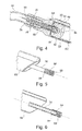
Figure 1 illustre l'accessoire d'implantation de l'invention et sa capsule, en situation, avec une représentation schématique de la voie d'accès fémorale et des cavités du coeur. - La
Figure 2 montre l'extrémité distale du cathéter téléorientable muni de son embout de protection, en position rétractée de la capsule leadless. - La
Figure 3 est une vue agrandie et en coupe de laFigure 2 , montrant la configuration générale des différents éléments internes ainsi que la capsule leadless logée à l'intérieur de l'embout de protection. - La
Figure 4 est une vue agrandie de la coupe de laFigure 3 , dans la région de la liaison avec l'extrémité proximale de la capsule leadless. - La
Figure 5 montre isolément le ressort hélicoïdal de compression radiale, monté à l'extrémité du sous-cathéter. - La
Figure 6 est une vue en coupe correspondant à laFigure 5 . - La
Figure 7 montre l'extrémité distale du cathéter téléorientable muni de son embout de protection, monté sur un fil-guide spiralé utilisé pour faire progresser cet embout depuis la ponction fémorale jusqu'au site d'implantation choisi. - La
Figure 8 montre l'extrémité distale du cathéter téléorientable muni de son embout de protection, avec la capsule leadless partiellement émergée de cet embout. - La
Figure 9 est une vue agrandie et en coupe de laFigure 8 , montrant la configuration générale des différents éléments internes. - La
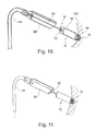
Figure 10 est une vue agrandie et en coupe homologue de laFigure 9 , une fois la capsule implantée au site choisi, après retrait du sous-cathéter et avec le fil de retenue toujours en place. - La
Figure 11 montre la configuration finale de la capsule et de l'accessoire d'implantation, dans la situation correspondant à celle de laFigure 10 .
- The
Figure 1 illustrates the implantation accessory of the invention and its capsule, in situation, with a schematic representation of the femoral access path and the cavities of the heart. - The
Figure 2 shows the distal end of the telerientable catheter with its protective tip, in the retracted position of the leadless capsule . - The
Figure 3 is an enlarged and sectional view of theFigure 2 , showing the general configuration of the various internal elements as well as the leadless capsule housed inside the protective tip. - The
Figure 4 is an enlarged view of the cup of theFigure 3 , in the region of the connection with the proximal end of the leadless capsule . - The
Figure 5 shows in isolation the helical spring of radial compression, mounted at the end of the sub-catheter. - The
Figure 6 is a sectional view corresponding to theFigure 5 . - The
Figure 7 shows the distal end of the telerientable catheter with its protective tip, mounted on a spiral guide wire used to advance this tip from the femoral puncture to the chosen implantation site. - The
Figure 8 shows the distal end of the telerientable catheter with its protective tip, with the leadless capsule partially emerged from this tip. - The
Figure 9 is an enlarged and sectional view of theFigure 8 , showing the general configuration of the various internal elements. - The
Figure 10 is an enlarged and cross-sectional view of theFigure 9 once the capsule is implanted at the chosen site, after removal of the sub-catheter and with the retaining wire still in place. - The
Figure 11 shows the final configuration of the capsule and the attachment accessory, in the situation corresponding to that of theFigure 10 .
On va maintenant décrire un exemple de réalisation du dispositif de l'invention.An embodiment of the device of the invention will now be described.
La
Une telle capsule leadless (représentée plus en détail notamment sur la
Le corps tubulaire 12 inclut divers moyens et circuits d'alimentation, de traitement du signal et de communication sans fil pour permettre l'échange de signaux avec un dispositif maitre distant, implanté ou non. Ces aspects sont en eux-mêmes connus et, comme ils ne font pas partie de l'invention, ils ne seront pas décrits.The
À son extrémité proximale 18, le corps tubulaire 12 de la capsule 10 comprend une tige d'arrimage axial 20 à extrémité arrondie dont on décrira plus loin le rôle lors de la procédure d'implantation. Cette tige d'arrimage 20 est lisse sur sa face extérieure et comporte un orifice axial taraudé interne, structure qui sera exposée plus en détail avec la description de la
La capsule leadless 10 est destinée à être implantée dans le ventricule droit 22, notamment au fond de ce ventricule, dans la région de l'apex 24. Pour une sonde de stimulation conventionnelle (reliée à un générateur distant), l'implantation se ferait typiquement par voie haute via la veine sous-clavière 26, comme illustré en tiretés en 28, de sorte que l'extrémité de la sonde se trouverait approximativement orientée dans l'axe ΔRV du ventricule droit et pourrait ainsi aisément traverser la valve tricuspide et parvenir à l'apex 24 du ventricule.The
En revanche, comme on l'a indiqué en introduction, cette voie d'approche n'est pas envisageable pour l'implantation de capsules leadless, dont les dimensions, et notamment le diamètre externe, sont très supérieures à ceux d'une tête de sonde conventionnelle.On the other hand, as indicated in the introduction, this approach is not conceivable for the implantation of leadless capsules , the dimensions of which, and in particular the external diameter, are much greater than those of a head of conventional probe.
Il est de ce fait nécessaire de procéder par voie basse, via la veine cave 30, depuis une ponction fémorale 32. Mais dans ce cas, l'axe d'approche, c'est-à-dire l'axe ΔVC de la veine cave, présente une très forte angulation (angle 34) avec l'axe ΔRV du ventricule droit, nécessitant de ce fait une manoeuvre pour former une courbure 36 au niveau de l'oreillette droite 38 afin de pouvoir faire passer l'accessoire d'implantation émergeant du sinus 40 de la veine cave jusqu'à la valve tricuspide 42 pour atteindre ensuite la cavité du ventricule droit 22.It is therefore necessary to proceed vaginally, via the
Des difficultés comparables se présentent pour une implantation dans le ventricule gauche, la voie d'accès impliquant alors une ponction fémorale artérielle et le passage de la crosse aortique.Similar difficulties arise for implantation in the left ventricle, the access route involving arterial femoral puncture and passage of the aortic arch.
Une telle manoeuvre peut être exécutée au moyen d'un cathéter téléorientable ("steerable"), qui est un accessoire en lui-même connu et tout à fait conventionnel comportant un tube de cathéter 44 manipulé depuis l'extrémité proximale par une poignée de manoeuvre 46 à la disposition du praticien. À l'aide des manettes 48, 48' celui-ci peut créer et régler une courbure 50 permettant d'orienter l'extrémité distale 52 du cathéter 44 de façon précise, typiquement avec une orientation pouvant aller jusqu'à 180° dans les deux directions avec un rayon de courbure variable, de l'ordre de 5 à 60 cm. La poignée 46 est également pourvue d'une voie latérale 54 de purge ainsi que d'une vanne de purge 56, caractéristiques en elles-mêmes tout à fait conventionnelles.Such a maneuver can be performed by means of a catheter téléorientable ( "steerable"), which is an accessory in itself known and entirely conventional catheter comprising a
Avec un cathéter téléorientable conventionnel, s'il est possible d'ajuster avec précision la courbure 50, il n'est pas possible de modifier la zone du cathéter où, sur sa longueur, cette courbure se forme. Or, dans le cas particulier illustré d'un abord fémoral avec comme cible le fond du ventricule droit, cette limitation peut être gênante avec certaines morphologies particulières présentant une cavité très allongée : en effet, la partie distale 52 du cathéter téléorientable située au-delà de la région 50 de la courbure peut s'avérer trop courte pour atteindre la région de l'apex 24.With a conventional teleorientable catheter, if it is possible to accurately adjust the
L'invention permet de pallier cette difficulté, comme on va l'expliquer ci-après, de sorte que la mise en oeuvre de l'invention est possible au moyen d'un cathéter téléorientable conventionnel du commerce, préexistant, permettant de réduire d'autant le cout de réalisation de l'accessoire d'implantation de l'invention.The invention makes it possible to overcome this difficulty, as will be explained hereinafter, so that the implementation of the invention is possible by means of a commercial conventional teleorientable catheter, pre-existing, which makes it possible to reduce as much as the cost of producing the implantation accessory of the invention.
Les
Le cathéter téléorientable 44 est muni à son extrémité distale d'un embout tubulaire de protection 58 comportant un logement central 60 (
Le diamètre extérieur du cathéter téléorientable 44 est typiquement compris entre 10 et 15 French (6,6 à 10 mm), pour un diamètre intérieur de lumière compris entre 8 et 12 French (2,66 à 4 mm). Quant à l'embout tubulaire 58, il doit pouvoir loger la capsule, donc présenter un diamètre intérieur de l'ordre de 21 French (7 mm)The outer diameter of the
Par ailleurs, un cathéter d'une telle taille doit nécessairement progresser dans le réseau veineux en étant guidé par un fil-guide spiralé préalablement introduit dans la vasculature.Moreover, a catheter of such a size must necessarily progress in the venous network being guided by a spiral guide wire previously introduced into the vasculature.
Comme, dans la conception illustrée, le canal central du cathéter 44 est obstrué par la capsule, pour permettre la mise en place d'un fil-guide l'embout tubulaire 58 est muni d'une lumière latérale excentrée 62 s'étendant axialement sur la longueur de l'embout et débouchant des deux côtés distal 64 et proximal 66, de préférence en s'étendant sur toute la longueur de l'embout 58. Le diamètre intérieur de cette lumière latérale 62 permet l'introduction d'un fil-guide spiralé conventionnel de diamètre 3 French (1 mm), et le coulissement de l'embout, et donc de l'ensemble du cathéter téléorientable 44, à travers la vasculature (cette configuration es notamment illustrée
En variante, la lumière latérale excentrée 62 peut être prolongée tout le long du corps du cathéter téléorientable 44, afin de faciliter la poussée du guide spiralé et éviter tout phénomène de bouclage de ce dernier.Alternatively, the
On notera que l'excentration de la lumière 62 combinée au profil biseauté de l'embout permet une progression aisée dans le réseau veineux par une technique "sidewire". Par ailleurs, la face avant 68, la plus distale, de l'embout 58 est profilée de manière à présenter une surface d'appui frontal minimale pour éviter tout risque de perforation en cas de manipulation accidentelle sans guide spiralé.Note that the eccentricity of the light 62 combined with the beveled profile of the tip allows easy progression in the venous network by a technique " sidewire " . Moreover, the
De plus, un marqueur radio-opaque 70 est prévu à l'avant de l'embout tubulaire 58 sur la face la plus distale de cet embout, afin d'identifier plus efficacement la sortie de la capsule si l'embout est réalisé dans un matériau radio-transparent.In addition, a radio-
Enfin, un ou plusieurs trous de purge 72 sont disposés côté proximal de l'embout, pour éviter tout effet de piston lors d'une injection de produit de contraste, qui sinon aurait pour conséquence de tendre à repousser la capsule 10 hors de l'embout de protection 58.Finally, one or more purge holes 72 are disposed proximally of the tip, to avoid any piston effect during an injection of contrast medium, which otherwise would have the effect of tending to push the
Le cathéter 44 est réalisé, de manière en elle-même connue, avec une structure armée, telle qu'un treillis métallique ou un bobinage noyé dans l'épaisseur de la paroi du cathéter, de manière à procurer une capacité de transmission du couple exercée sur la poignée de manoeuvre proximale jusqu'à l'extrémité distale (structure armée 74).The
L'accessoire d'implantation de l'invention comprend en outre, de façon caractéristique, un sous-cathéter 76, introduit dans la lumière centrale du cathéter téléorientable 44, et mobile en rotation et en translation par rapport à ce dernier. La fonction de ce sous-cathéter 76 est d'assurer le déploiement de la capsule hors de l'embout de protection et d'avancer cette capsule jusqu'au site d'implantation par un mouvement de translation sur une longueur suffisante, typiquement de 2 à 6 cm en fonction de l'anatomie du patient (la flèche 78 indique la translation du sous-cathéter 76 à l'intérieur du cathéter téléorientable 44, et la flèche 80 indique la translation de la capsule 10 hors de l'embout de protection 58).The implantation accessory of the invention further comprises, typically, a sub-catheter 76, introduced into the central lumen of the
Le sous-cathéter 76 a également pour fonction d'assurer la transmission d'un couple de rotation depuis l'extrémité proximale (au niveau de la poignée de manoeuvre) jusqu'à son extrémité distale, et il est muni à cet effet d'une structure armée 82.The sub-catheter 76 also serves to ensure the transmission of a torque from the proximal end (at the operating handle) to its distal end, and is provided for this purpose an
Il est possible d'utiliser pour le sous-cathéter 76 un cathéter-guide conventionnel de 4 à 6 French (1,33 à 2 mm), qui est un dispositif existant, simple et économique, répondant aux contraintes courantes de transmission du couple, de faible coefficient de frottement à l'intérieur et à l'extérieur, de flexibilité, etc., et qui dispose d'une connectique "Luer-Lok" proximale permettant le montage rapide d'un adaptateur multifonction tel qu'une valve hémostatique rotationnelle ou autre adaptateur compatible avec ce standard de connexion étanche. Subsidiairement, le sous-cathéter 76 permet d'injecter un produit de contraste jusqu'à l'arrière de la capsule 10 de manière à suivre avec précision l'opération sous amplificateur de brillance.It is possible to use for the sub-catheter 76 a conventional guide catheter of 4 to 6 French (1.33 to 2 mm), which is an existing device, simple and economical, responding to the current constraints of torque transmission, low coefficient of friction inside and outside, flexibility, etc., and which has a proximal "Luer-Lok" connection allowing the quick assembly of a multifunctional adapter such as a rotational hemostatic valve or other adapter compatible with this standard waterproof connection. Alternatively, the sub-catheter 76 can inject a contrast medium to the back of the
On va maintenant décrire en détail le moyen de couplage du sous-cathéter 76 à la capsule 10.The means for coupling the sub-catheter 76 to the
Ce moyen de couplage représente en soi un aspect original de l'invention, généralisable au couplage d'un dispositif d'implantation comprenant un élément tubulaire allongé creux (comme un cathéter) ou non, avec un dispositif médical autonome (comme une capsule leadless) ou non (comme une tête de sonde d'une sonde de stimulation), ce dispositif étant pourvu à son extrémité distale d'un organe d'ancrage apte à pénétrer dans un tissu corporel, cardiaque ou autre.This coupling means represents in itself an original aspect of the invention, generalizable to the coupling of an implantation device comprising a hollow elongate tubular element (like a catheter) or not, with an autonomous medical device (such as a leadless capsule). or not (as a probe head of a stimulation probe), this device being provided at its distal end with an anchoring member capable of penetrating into a body tissue, heart or other.
Le moyen de couplage selon l'invention met en oeuvre un ressort hélicoïdal 84 qui est utilisé non pas pour ses propriétés d'élasticité en traction/compression axiale (effet résultant de l'allongement ou du rapprochement des spires du ressort), mais pour ses propriétés de compression radiale, c'est-à-dire pour l'effet de striction ou étranglement qu'un tel ressort peut exercer autour d'un noyau central introduit à l'intérieur de la forme hélicoïdale.The coupling means according to the invention implements a
La géométrie du ressort et l'élasticité du matériau qui le constitue sont choisies de manière à réaliser entre le ressort et le noyau central, en l'absence de sollicitation extérieure, un ajustement avec serrage (la compression radiale résultant de l'effet de striction).The geometry of the spring and the elasticity of the material constituting it are chosen so as to form between the spring and the central core, in the absence of external stress, an interference fit (the radial compression resulting from the necking effect). ).
Dans l'exemple illustré
Ce ressort 84 est illustré plus précisément et de façon isolée sur les Figures 5 et 6.This
Le ressort 84, quant à lui, est solidarisé à l'extrémité distale du sous-cathéter 76 par des spires 86. Cette solidarisation en translation et en rotation, par exemple par soudage ou collage, devra être conservée quel que soit le degré des contraintes normalement appliquées au sous-cathéter 76 et au ressort 84.The
Les spires 88 situées côté distal du ressort 84 sont, en revanche, des spires libres, qui viennent entourer la tige d'arrimage 20 mais qui ne sont pas solidarisées mécaniquement à cette dernière autrement que par l'ajustement avec serrage obtenu dans la configuration statique de ces deux éléments. Par ailleurs, l'extrémité distale du ressort 84 est avantageusement une extrémité arrondie, afin d'éviter de blesser les tissus et de s'accrocher lors des différentes manipulations.The turns 88 located on the distal side of the
Les spires inactives 86 et/ou les spires actives 88 peuvent être indifféremment jointives ou non jointives.The inactive turns 86 and / or the active turns 88 may be indifferently joined or non-joined.
Une fois que la capsule 10 est immobilisée au site d'implantation après pénétration complète de la vis d'ancrage 14 jusqu'à la face avant de la capsule, le praticien continue de faire tourner le sous-cathéter 76, générant ainsi un surcouple qui a pour effet de diminuer l'effort de striction exercé par les spires libres 88 sur la tige d'arrimage 20, jusqu'à provoquer le glissement en rotation de ces spires sur cette même tige. En combinant à ce mouvement de rotation un léger effort de traction, le ressort de compression 84 se dégage de la tige d'arrimage 20, libérant ainsi la capsule 10 d'avec le ressort 84, et donc d'avec le sous-cathéter 76.Once the
Le ressort de compression radiale 84 joue ainsi un rôle de limiteur de couple. En effet, avec une vis d'ancrage d'une capsule leadless standard, si le praticien poursuivait la rotation du sous-cathéter 76 et donc de la capsule 10, le couple augmenterait et dépasserait une limite Ccarottage, la vis d'ancrage risquant alors de déchirer localement les tissus sous l'effet de la rotation de la vis sans avance de celle-ci, jusqu'à provoquer une lacération des tissus et, à l'extrême, une perforation de la paroi avec risque de tamponnade. Tel n'est pas le cas avec le moyen proposé par l'invention : le praticien peut en effet poursuivre sans risque la rotation du sous-cathéter 76, toujours dans le même sens (généralement le sens horaire), car le couple supplémentaire apparaissant du fait de la réaction de la vis d'ancrage ancrée dans les tissus est absorbé par la liaison entre le ressort 84 et la tige d'arrimage 20 (phénomène de montée brusque du couple retour lorsque la face avant de la capsule touche le tissu cardiaque). Plus précisément, la géométrie et l'élasticité du ressort 84 sont choisies de manière à définir un couple limite prédéfini Clargage inférieur à la limite Ccarottage du carottage correspondant à un couple limite de maintien de la vis d'ancrage dans le tissu du site d'implantation, sans carottage de ce tissu, tout en garantissant un vissage complet (tissus en contact avec la face avant de la capsule). De la sorte, lorsque le couple Cdébrayage est atteint, la poursuite de la rotation du sous-cathéter 76 dans le sens horaire provoque, en combinaison avec un léger effort de traction, le dégagement progressif du ressort 84 d'avec la tige d'arrimage 20 (s'il y a surcouple, les spires du ressort radial glissent en rotation sur le noyau d'arrimage donc ne transmettent plus d'élévation du couple).The
Le couple de débrayage Cdébrayage est par exemple ajusté à une valeur typique de l'ordre de 0,2 à 0,8 N.cm.C clutch release torque is for example adjusted to a typical value of about 0.2 to 0.8 N.cm.
Par ailleurs, dans une configuration statique, l'effort de striction de la partie libre 88 du ressort 84 sur la tige d'arrimage 20 est choisi de manière à empêcher tout désassemblage accidentel par un effort de traction (effort orienté axialement) inférieur à un seuil suffisant, typiquement un seuil qui assure un maintien même pour une traction exercée sur le sous-cathéter 76 avec un effort allant jusqu'à 20 N.Furthermore, in a static configuration, the necking force of the
On notera par ailleurs que si l'on souhaite dévisser la capsule, par exemple parce qu'après une première implantation on constate que les performances électriques du site ne sont pas satisfaisantes, le système de couplage par le ressort 84 ne produira aucun effet de débrayage au dévissage, car le ressort sera alors entrainé en rotation inverse (généralement dans le sens antihoraire) ce qui aura pour effet d'augmenter encore plus le serrage des spires 88 sur la tige d'arrimage 20.Note also that if it is desired to unscrew the capsule, for example because after a first implementation we find that the electrical performance of the site is not satisfactory, the coupling system by the
Un autre avantage du ressort 84 est qu'après largage de la capsule le dispositif d'implantation se présentera à son extrémité sous la forme illustréeAnother advantage of the
Enfin, on notera que le limiteur de couple constitué par le ressort 84 est idéalement situé dans la chaine de transmission des efforts : plus précisément, toute perte de fidélité dans la transmission du couple entre l'extrémité proximale du sous-cathéter 76 (c'est-à-dire depuis la poignée manipulée par le praticien) et son extrémité distale (là où se trouve le ressort de couplage 84) est sans effet sur le couple maximal ou minimal subi à l'interface entre la vis d'ancrage et les tissus, ce qui est un gage d'une fixation complète - ce qui ne serait pas le cas pour un système débrayable situé plus en amont, typiquement dans la poignée de manipulation 46. On notera par ailleurs que l'ensemble de ces fonctionnalités est obtenu via un composant très économique, de conception très simple et très compact. Le largage de la capsule peut ainsi s'effectuer par un mouvement combiné de vissage puis de traction, en deux étapes :
- vissage de la capsule dans la paroi cardiaque, par une rotation dans le sens horaire du sous-cathéter 76 (par exemple sur 10 tours), sous une légère poussée, puis
- largage de la capsule, par une poursuite de la rotation horaire du sous-cathéter 76 (par exemple sur 5 tours), sous une légère traction afin de permettre le retrait du sous-cathéter après desserrage du ressort 84.
- screwing the capsule into the cardiac wall, by a clockwise rotation of the sub-catheter 76 (for example over 10 turns), under a slight thrust, and then
- release of the capsule, by continuing the hourly rotation of the sub-catheter 76 (for example over 5 turns), under a slight traction to allow the removal of the sub-catheter after loosening the
spring 84.
Pour obtenir ce résultat, le sens des spires du ressort est bien évidemment choisi dans le même sens que celui de la vis d'ancrage, de préférence avec un pas à droite pour que le vissage de la capsule puis son largage correspondent à une rotation du sous-cathéter 76 dans le sens horaire, le plus conventionnel.To obtain this result, the direction of the turns of the spring is obviously chosen in the same direction as that of the anchor screw, preferably with a step to the right so that the screwing of the capsule and its release correspond to a rotation of the sub-catheter 76 clockwise, the most conventional.
Avantageusement, le nécessaire d'implantation comprend également un fil de sécurité ou fil de retenue 90 de type "fil d'Ariane" relié à la capsule 10 du côté distal, s'étendant sur toute la longueur du sous-cathéter 76 et dépassant de ce dernier du côté proximal, c'est-à-dire du côté de la poignée de manoeuvre 46.Advantageously, the implantation kit also comprises a safety wire or retaining
Comme illustré sur les
Une fois le cathéter orientable 44 et le sous-cathéter 76 complètement retirés, le fil de retenue permet de récupérer la capsule en per-opératoire, avec réintroduction de l'accessoire d'implantation en faisant glisser celui-ci le long du fil de retenue jusqu'à ce que l'embout de protection 58 vienne coiffer la capsule.Once the
Cette dernière pourra alors être réaccouplée au sous-cathéter par une rotation dans le sens horaire (la fonctionnalité de limiteur de couple étant toujours efficace), puis dévissée de la paroi 100 par une rotation dans le sens antihoraire et replacée sur un autre site par le même principe que ce qui a été décrit plus haut, par une rotation dans le sens horaire du sous-cathéter.The latter can then be re-coupled to the sub-catheter by a rotation in the clockwise direction (the torque limiter function being always effective), then unscrewed from the
Le fil de retenue est par exemple un fil de 1 French (0,43 mm) de diamètre comportant à son extrémité distale 92 un filetage 94 apte à coopérer avec un taraudage homologue 96 réalisé dans un alésage axial taraudé de l'axe d'arrimage 20 (
Le fil de retenue peut être coloré de couleurs différentes pour chacune des capsules implantées, de manière à identifier plus facilement la capsule concernée dans l'éventualité d'une réintervention.The retaining wire may be colored with different colors for each implanted capsule, so as to identify more easily the capsule concerned in the event of a reoperation.
La technique de l'invention procure donc une triple sécurité grâce au système de débrayage qui permet lors du largage de la capsule :
- de garantir un vissage complet de la capsule dans les tissus ;
- d'éviter tout carottage de la paroi cardiaque ; et
- de garantir au praticien de pouvoir en cas de difficulté récupérer après largage la capsule grâce au fil de retenue.
- to guarantee a complete screwing of the capsule in the tissues;
- to avoid any coring of the cardiac wall; and
- to guarantee to the practitioner of power in case of difficulty to recover after release the capsule thanks to the retaining wire.
La procédure de mise en place de la capsule leadless au moyen de l'accessoire d'implantation que l'on vient de décrire comprend les étapes suivantes, qui sont chacune relativement conventionnelles et peuvent être aisément réalisées par un praticien sans nécessiter d'habilité particulière ni de manoeuvres supplémentaires :
- ponction fémorale, droite ou gauche, de manière à accéder à la veine cave inférieure 30 ;
- mise en place optionnelle d'un introducteur 23 French (7,66 mm) hémostatique en percutané ;
- insertion du cathéter téléorientable 44 sur un fil-guide spiralé (illustré en 98 sur la
Figure 7 ), typiquement un fil-guide de 3 French (1 mm) sur lequel l'embout tubulaire 58, et donc le cathéter téléorientable 44 pourront coulisser et progresser jusqu'à l'oreillette droite 38 ; - manoeuvre de retournement de l'extrémité du cathéter téléorientable 44 (comme illustré en 36 sur la
Figure 1 ), puis introduction de l'embout 58 dans le ventricule droit ; - sortie de la
capsule 10 jusqu'à l'apex du ventricule par translation du sous-cathéter 76 dans le cathéter téléorientable 44 (configuration illustréeFigure 9 ) ; - visualisation des parois cardiaques par injection de produit de contraste via le sous-cathéter ;
- positionnement fin de la capsule au site cible choisi, avec possibilité de translation une fois dans la cavité cardiaque par déploiement plus ou moins important du sous-
cathéter 76 hors du cathéter téléorientable 44, permettant un ajustement fin convenant à une grande diversité d'anatomies ; - vissage de la capsule dans la paroi cardiaque jusqu'à débrayage du ressort de
compression radiale 84 ; - séparation du sous-
cathéter 76 d'avec lacapsule 10, et retrait du sous-cathéter 76 hors du cathéter téléorientable 44 (configuration illustréeFigure 10 ) ; - test électrique de la capsule ;
- retrait complet du cathéter téléorientable 44 et du sous-
cathéter 76 ; - largage définitif de la capsule, avec retrait du fil de retenue 90 par un dévissage à faible couple ; et
- fermeture du point de ponction.
- femoral puncture, right or left, to access the
inferior vena cava 30; - optional placement of a 23 French (7.66 mm) haemostatic percutaneous introducer;
- insertion of the
telerientable catheter 44 onto a spiral guidewire (illustrated at 98 on theFigure 7 ), typically a 3 French (1 mm) guide wire on which thetubular tip 58, and thus theteleorientable catheter 44 can slide and progress to theright atrium 38; - reversing operation of the end of the telerientable catheter 44 (as illustrated at 36 on the
Figure 1 ), then introduction of thetip 58 into the right ventricle; - exiting the
capsule 10 to the apex of the ventricle by translating the sub-catheter 76 into the teleorientable catheter 44 (illustrated configurationFigure 9 ); - visualization of the cardiac walls by injection of contrast medium via the sub-catheter;
- fine positioning of the capsule at the chosen target site, with possibility of translation once in the heart chamber by more or less significant deployment of the sub-catheter 76 out of the
telerientable catheter 44, allowing fine adjustment suitable for a wide variety of anatomies; - screwing the capsule into the cardiac wall until disengagement of the
radial compression spring 84; - separating the sub-catheter 76 from the
capsule 10, and removing the sub-catheter 76 from the teleorientable catheter 44 (illustrated configurationFigure 10 ); - electrical test of the capsule;
- complete removal of the
telerientable catheter 44 and the sub-catheter 76; - final release of the capsule, with withdrawal of the
retaining wire 90 by a low torque unscrewing; and - closing of the puncture site.
Claims (5)
ces moyens découplables de support et de guidage comprenant un ressort hélicoïdal (84) coopérant avec un noyau central (20) et étant des moyens aptes à solidariser en translation et en rotation mutuelles l'élément tubulaire de l'accessoire d'implantation et le dispositif médical, et aptes à découpler le dispositif médical d'avec l'élément tubulaire de l'accessoire d'implantation sous l'effet d'une rotation appliquée à l'élément tubulaire depuis l'extrémité proximale de celui-ci, et
these decoupling means of support and guiding comprising a helical spring (84) cooperating with a central core (20) and being means able to join in mutual translation and rotation the tubular element of the implantation accessory and the device medical device, and able to uncouple the medical device from the tubular element of the implantation accessory under the effect of a rotation applied to the tubular element from the proximal end thereof, and
Applications Claiming Priority (1)
| Application Number | Priority Date | Filing Date | Title |
|---|---|---|---|
| FR1356021 | 2013-06-24 |
Publications (2)
| Publication Number | Publication Date |
|---|---|
| EP2818202A1 true EP2818202A1 (en) | 2014-12-31 |
| EP2818202B1 EP2818202B1 (en) | 2016-04-13 |
Family
ID=49237361
Family Applications (1)
| Application Number | Title | Priority Date | Filing Date |
|---|---|---|---|
| EP14165464.0A Active EP2818202B1 (en) | 2013-06-24 | 2014-04-22 | Coupling system between a medical device and an accessory for in situ implantation thereof |
Country Status (2)
| Country | Link |
|---|---|
| US (3) | US9974948B2 (en) |
| EP (1) | EP2818202B1 (en) |
Cited By (4)
| Publication number | Priority date | Publication date | Assignee | Title |
|---|---|---|---|---|
| EP3173126A1 (en) | 2015-11-27 | 2017-05-31 | Sorin CRM SAS | Implantable capsule, in particular an autonomous cardiac stimulation capsule |
| CN107106849A (en) * | 2015-01-16 | 2017-08-29 | 美敦力公司 | Interventional medical instrument and component |
| WO2018195071A1 (en) * | 2017-04-18 | 2018-10-25 | Cardiac Pacemakers, Inc. | Active medical device with attachment features |
| US10124163B2 (en) | 2014-04-08 | 2018-11-13 | Sorin Crm Sas | Intracardiac capsule and explantation accessory |
Families Citing this family (17)
| Publication number | Priority date | Publication date | Assignee | Title |
|---|---|---|---|---|
| WO2014089545A1 (en) * | 2012-12-07 | 2014-06-12 | Purdue Research Foundation | Feedback system and method for assessing fixation and stability of implantable leads |
| EP2818202B1 (en) | 2013-06-24 | 2016-04-13 | Sorin CRM SAS | Coupling system between a medical device and an accessory for in situ implantation thereof |
| EP2818201B1 (en) | 2013-06-24 | 2016-07-20 | Sorin CRM SAS | Intracardiac capsule and accessory for in situ implantation by the femoral route |
| EP3069754B1 (en) * | 2015-03-16 | 2017-10-25 | Sorin CRM SAS | In situ implantation accessory for self-contained intracardiac capsule |
| US10668294B2 (en) * | 2016-05-10 | 2020-06-02 | Cardiac Pacemakers, Inc. | Leadless cardiac pacemaker configured for over the wire delivery |
| EP3248649B1 (en) * | 2016-05-24 | 2019-01-02 | Sorin CRM SAS | A torque limiting mechanism between a medical device and its implantation accessory |
| US10881868B2 (en) * | 2016-05-24 | 2021-01-05 | Sorin Crm Sas | Torque limiting mechanism between a medical device and its implantation accessory |
| CN110167621B (en) * | 2017-01-17 | 2021-08-06 | 美敦力公司 | Shuttle apparatus for removably coupling a catheter to a guidewire and associated systems and methods |
| FR3086179B1 (en) | 2018-09-25 | 2020-09-25 | Cairdac | IMPLANTABLE AUTONOMOUS HEART CAPSULE WITH ADJUSTABLE HEAD AND TORQUE LIMITER |
| US10967151B2 (en) | 2019-01-01 | 2021-04-06 | Cairdac | Steerable catheter for the implantation of a leadless cardiac capsule |
| EP3946556A1 (en) | 2019-03-29 | 2022-02-09 | Cardiac Pacemakers, Inc. | Systems and methods for treating cardiac arrhythmias |
| US11833349B2 (en) | 2019-03-29 | 2023-12-05 | Cardiac Pacemakers, Inc. | Systems and methods for treating cardiac arrhythmias |
| US11571582B2 (en) | 2019-09-11 | 2023-02-07 | Cardiac Pacemakers, Inc. | Tools and systems for implanting and/or retrieving a leadless cardiac pacing device with helix fixation |
| WO2021050679A1 (en) | 2019-09-11 | 2021-03-18 | Cardiac Pacemakers, Inc. | Tools and systems for implanting and/or retrieving a leadless cardiac pacing device with helix fixation |
| EP4059565B1 (en) * | 2021-03-15 | 2022-11-23 | Cairdac | Implantable and removable autonomous cardiac capsule with adjustable head and torque limiter |
| WO2023235707A1 (en) * | 2022-06-01 | 2023-12-07 | Medtronic, Inc. | Delivery system for over the wire implantation of a medical device |
| CN116421284B (en) * | 2023-06-15 | 2023-08-18 | 创领心律管理医疗器械(上海)有限公司 | Torque transmission mechanism, assembly method and conveying device of implantable medical device |
Citations (4)
| Publication number | Priority date | Publication date | Assignee | Title |
|---|---|---|---|---|
| US20070135883A1 (en) * | 2005-12-09 | 2007-06-14 | Boston Scientific Scimed, Inc. | Cardiac Stimulation system |
| US20090204170A1 (en) * | 2008-02-07 | 2009-08-13 | Cardiac Pacemakers, Inc. | Wireless tissue electrostimulation |
| EP2394695A1 (en) | 2010-06-14 | 2011-12-14 | Sorin CRM SAS | Standalone intracardiac capsule and implantation accessory |
| US20120095539A1 (en) | 2010-10-13 | 2012-04-19 | Alexander Khairkhahan | Delivery Catheter Systems and Methods |
Family Cites Families (11)
| Publication number | Priority date | Publication date | Assignee | Title |
|---|---|---|---|---|
| FR2790966B1 (en) | 1999-03-17 | 2001-05-04 | Ela Medical Sa | LEFT EARCUTE STIMULATION PROBE IMPLANTABLE IN THE CORONARY VENOUS NETWORK FOR ACTIVE IMPLANTABLE MEDICAL DEVICE, IN PARTICULAR "MULTISITE" TYPE STIMULATOR |
| WO2001054761A2 (en) | 2000-01-28 | 2001-08-02 | William Cook, Europe Aps | Endovascular medical device with plurality of wires |
| US20040082879A1 (en) | 2000-01-28 | 2004-04-29 | Klint Henrik S. | Endovascular medical device with plurality of wires |
| US6611710B2 (en) | 2000-11-29 | 2003-08-26 | Pacesetter, Inc. | Double threaded stylet for extraction of leads with a threaded electrode |
| FR2859912B1 (en) | 2003-09-22 | 2005-11-18 | Ela Medical Sa | NECESSARY FOR DRILLING THE CARDIAC SEPTUM AND PLACING A TRANSSEPTAL DEVICE, IN PARTICULAR A STIMULATION PROBE OF A LEFT CAVITY |
| ATE531420T1 (en) | 2009-04-28 | 2011-11-15 | Sorin Crm Sas | INTRACARDIAL SENSOR FOR STIMULATION OR DEFIBRILLATION WITH RETRACTABLE SCREW |
| EP2485679A1 (en) | 2009-10-08 | 2012-08-15 | Cook Incorporated | Vascular implant retrieval assembly and tool for the same |
| AU2011240927B2 (en) | 2010-04-14 | 2015-07-16 | Microvention, Inc. | Implant delivery device |
| EP2651494B1 (en) | 2010-12-13 | 2017-02-15 | Pacesetter, Inc. | Delivery catheter |
| EP2818201B1 (en) | 2013-06-24 | 2016-07-20 | Sorin CRM SAS | Intracardiac capsule and accessory for in situ implantation by the femoral route |
| EP2818202B1 (en) | 2013-06-24 | 2016-04-13 | Sorin CRM SAS | Coupling system between a medical device and an accessory for in situ implantation thereof |
-
2014
- 2014-04-22 EP EP14165464.0A patent/EP2818202B1/en active Active
- 2014-06-23 US US14/312,410 patent/US9974948B2/en active Active
-
2018
- 2018-05-18 US US15/984,307 patent/US10933235B2/en active Active
-
2021
- 2021-01-05 US US17/141,384 patent/US20210121689A1/en active Pending
Patent Citations (4)
| Publication number | Priority date | Publication date | Assignee | Title |
|---|---|---|---|---|
| US20070135883A1 (en) * | 2005-12-09 | 2007-06-14 | Boston Scientific Scimed, Inc. | Cardiac Stimulation system |
| US20090204170A1 (en) * | 2008-02-07 | 2009-08-13 | Cardiac Pacemakers, Inc. | Wireless tissue electrostimulation |
| EP2394695A1 (en) | 2010-06-14 | 2011-12-14 | Sorin CRM SAS | Standalone intracardiac capsule and implantation accessory |
| US20120095539A1 (en) | 2010-10-13 | 2012-04-19 | Alexander Khairkhahan | Delivery Catheter Systems and Methods |
Cited By (8)
| Publication number | Priority date | Publication date | Assignee | Title |
|---|---|---|---|---|
| US10124163B2 (en) | 2014-04-08 | 2018-11-13 | Sorin Crm Sas | Intracardiac capsule and explantation accessory |
| US10874852B2 (en) | 2014-04-08 | 2020-12-29 | Sorin Crm Sas | Intracardiac capsule and explantation accessory |
| CN107106849A (en) * | 2015-01-16 | 2017-08-29 | 美敦力公司 | Interventional medical instrument and component |
| CN107106849B (en) * | 2015-01-16 | 2020-06-12 | 美敦力公司 | Interventional medical tools and assemblies |
| EP3173126A1 (en) | 2015-11-27 | 2017-05-31 | Sorin CRM SAS | Implantable capsule, in particular an autonomous cardiac stimulation capsule |
| US10105535B2 (en) | 2015-11-27 | 2018-10-23 | Sorin Crm Sas | Implantable stimulation capsule |
| WO2018195071A1 (en) * | 2017-04-18 | 2018-10-25 | Cardiac Pacemakers, Inc. | Active medical device with attachment features |
| US11077297B2 (en) | 2017-04-18 | 2021-08-03 | Cardiac Pacemakers, Inc. | Active medical device with attachment features |
Also Published As
| Publication number | Publication date |
|---|---|
| US10933235B2 (en) | 2021-03-02 |
| US20210121689A1 (en) | 2021-04-29 |
| EP2818202B1 (en) | 2016-04-13 |
| US20140378992A1 (en) | 2014-12-25 |
| US9974948B2 (en) | 2018-05-22 |
| US20180264256A1 (en) | 2018-09-20 |
Similar Documents
| Publication | Publication Date | Title |
|---|---|---|
| EP2818201B1 (en) | Intracardiac capsule and accessory for in situ implantation by the femoral route | |
| EP2818202B1 (en) | Coupling system between a medical device and an accessory for in situ implantation thereof | |
| EP3069754B1 (en) | In situ implantation accessory for self-contained intracardiac capsule | |
| EP2929910B1 (en) | Intracardiac capsule and accessory for explanting same | |
| EP2881141B1 (en) | Implantable intracardiac capsule on a thin wall, in particular the septal wall | |
| EP2394695B1 (en) | Standalone intracardiac capsule and implantation accessory | |
| EP2327366B1 (en) | Kit for piercing the cardiac septum and implanting a transseptal probe, in particular a probe for detection/stimulation of a left cavity of the heart | |
| EP1516644B1 (en) | Device for piercing the septum and for placing a stimulation transeptal device at the left part | |
| EP2246091B1 (en) | Endocardiac stimulation or defibrillation probe with a retractable screw | |
| EP2719424B1 (en) | Intraseptal probe for left ventricular stimulation | |
| EP2384784B1 (en) | Assembly for endocavitary stimulation/defibrillation of the left ventricle | |
| EP3405258A1 (en) | Interventional medical systems | |
| EP2457612A1 (en) | Unit for stimulation/defibrillation of the left ventricle via the endocavity or from a vein of the coronary network | |
| EP3639884B1 (en) | Coupling system between a leadless cardiac implant and associated implantation tool | |
| EP3006082B1 (en) | Accessory for explantation of an intracorporeal capsule | |
| EP0784993B1 (en) | Electrode lead for implanted medical device, especially for heart pacemaker | |
| EP4059565B1 (en) | Implantable and removable autonomous cardiac capsule with adjustable head and torque limiter | |
| EP1374945B1 (en) | Coronary probe with improved retaining means | |
| FR2932688A1 (en) | Guidance mandrin for probe i.e. cardiac stimulation or detection probe, of cardiac stimulation implant, has wire comprising distal part of ductile material to produce permanent flexion deformation under effect of stress applied to hand | |
| CA2047280A1 (en) | Apparatus for temporary implantation of a blood filter in a human vein |
Legal Events
| Date | Code | Title | Description |
|---|---|---|---|
| PUAI | Public reference made under article 153(3) epc to a published international application that has entered the european phase |
Free format text: ORIGINAL CODE: 0009012 |
|
| 17P | Request for examination filed |
Effective date: 20140422 |
|
| AK | Designated contracting states |
Kind code of ref document: A1 Designated state(s): AL AT BE BG CH CY CZ DE DK EE ES FI FR GB GR HR HU IE IS IT LI LT LU LV MC MK MT NL NO PL PT RO RS SE SI SK SM TR |
|
| AX | Request for extension of the european patent |
Extension state: BA ME |
|
| R17P | Request for examination filed (corrected) |
Effective date: 20150402 |
|
| RBV | Designated contracting states (corrected) |
Designated state(s): AL AT BE BG CH CY CZ DE DK EE ES FI FR GB GR HR HU IE IS IT LI LT LU LV MC MK MT NL NO PL PT RO RS SE SI SK SM TR |
|
| RIC1 | Information provided on ipc code assigned before grant |
Ipc: A61N 1/375 20060101AFI20150908BHEP Ipc: A61N 1/372 20060101ALI20150908BHEP Ipc: A61N 1/05 20060101ALI20150908BHEP |
|
| GRAP | Despatch of communication of intention to grant a patent |
Free format text: ORIGINAL CODE: EPIDOSNIGR1 |
|
| INTG | Intention to grant announced |
Effective date: 20151020 |
|
| GRAS | Grant fee paid |
Free format text: ORIGINAL CODE: EPIDOSNIGR3 |
|
| GRAA | (expected) grant |
Free format text: ORIGINAL CODE: 0009210 |
|
| AK | Designated contracting states |
Kind code of ref document: B1 Designated state(s): AL AT BE BG CH CY CZ DE DK EE ES FI FR GB GR HR HU IE IS IT LI LT LU LV MC MK MT NL NO PL PT RO RS SE SI SK SM TR |
|
| REG | Reference to a national code |
Ref country code: GB Ref legal event code: FG4D Free format text: NOT ENGLISH |
|
| REG | Reference to a national code |
Ref country code: AT Ref legal event code: REF Ref document number: 789464 Country of ref document: AT Kind code of ref document: T Effective date: 20160415 Ref country code: CH Ref legal event code: EP |
|
| REG | Reference to a national code |
Ref country code: FR Ref legal event code: PLFP Year of fee payment: 3 |
|
| REG | Reference to a national code |
Ref country code: IE Ref legal event code: FG4D Free format text: LANGUAGE OF EP DOCUMENT: FRENCH |
|
| REG | Reference to a national code |
Ref country code: DE Ref legal event code: R096 Ref document number: 602014001454 Country of ref document: DE |
|
| REG | Reference to a national code |
Ref country code: LT Ref legal event code: MG4D |
|
| PG25 | Lapsed in a contracting state [announced via postgrant information from national office to epo] |
Ref country code: BE Free format text: LAPSE BECAUSE OF NON-PAYMENT OF DUE FEES Effective date: 20160430 |
|
| REG | Reference to a national code |
Ref country code: AT Ref legal event code: MK05 Ref document number: 789464 Country of ref document: AT Kind code of ref document: T Effective date: 20160413 |
|
| REG | Reference to a national code |
Ref country code: NL Ref legal event code: MP Effective date: 20160413 |
|
| PG25 | Lapsed in a contracting state [announced via postgrant information from national office to epo] |
Ref country code: FI Free format text: LAPSE BECAUSE OF FAILURE TO SUBMIT A TRANSLATION OF THE DESCRIPTION OR TO PAY THE FEE WITHIN THE PRESCRIBED TIME-LIMIT Effective date: 20160413 Ref country code: LT Free format text: LAPSE BECAUSE OF FAILURE TO SUBMIT A TRANSLATION OF THE DESCRIPTION OR TO PAY THE FEE WITHIN THE PRESCRIBED TIME-LIMIT Effective date: 20160413 Ref country code: NO Free format text: LAPSE BECAUSE OF FAILURE TO SUBMIT A TRANSLATION OF THE DESCRIPTION OR TO PAY THE FEE WITHIN THE PRESCRIBED TIME-LIMIT Effective date: 20160713 Ref country code: PL Free format text: LAPSE BECAUSE OF FAILURE TO SUBMIT A TRANSLATION OF THE DESCRIPTION OR TO PAY THE FEE WITHIN THE PRESCRIBED TIME-LIMIT Effective date: 20160413 Ref country code: NL Free format text: LAPSE BECAUSE OF FAILURE TO SUBMIT A TRANSLATION OF THE DESCRIPTION OR TO PAY THE FEE WITHIN THE PRESCRIBED TIME-LIMIT Effective date: 20160413 |
|
| PG25 | Lapsed in a contracting state [announced via postgrant information from national office to epo] |
Ref country code: RS Free format text: LAPSE BECAUSE OF FAILURE TO SUBMIT A TRANSLATION OF THE DESCRIPTION OR TO PAY THE FEE WITHIN THE PRESCRIBED TIME-LIMIT Effective date: 20160413 Ref country code: GR Free format text: LAPSE BECAUSE OF FAILURE TO SUBMIT A TRANSLATION OF THE DESCRIPTION OR TO PAY THE FEE WITHIN THE PRESCRIBED TIME-LIMIT Effective date: 20160714 Ref country code: SE Free format text: LAPSE BECAUSE OF FAILURE TO SUBMIT A TRANSLATION OF THE DESCRIPTION OR TO PAY THE FEE WITHIN THE PRESCRIBED TIME-LIMIT Effective date: 20160413 Ref country code: HR Free format text: LAPSE BECAUSE OF FAILURE TO SUBMIT A TRANSLATION OF THE DESCRIPTION OR TO PAY THE FEE WITHIN THE PRESCRIBED TIME-LIMIT Effective date: 20160413 Ref country code: AT Free format text: LAPSE BECAUSE OF FAILURE TO SUBMIT A TRANSLATION OF THE DESCRIPTION OR TO PAY THE FEE WITHIN THE PRESCRIBED TIME-LIMIT Effective date: 20160413 Ref country code: LV Free format text: LAPSE BECAUSE OF FAILURE TO SUBMIT A TRANSLATION OF THE DESCRIPTION OR TO PAY THE FEE WITHIN THE PRESCRIBED TIME-LIMIT Effective date: 20160413 Ref country code: ES Free format text: LAPSE BECAUSE OF FAILURE TO SUBMIT A TRANSLATION OF THE DESCRIPTION OR TO PAY THE FEE WITHIN THE PRESCRIBED TIME-LIMIT Effective date: 20160413 Ref country code: PT Free format text: LAPSE BECAUSE OF FAILURE TO SUBMIT A TRANSLATION OF THE DESCRIPTION OR TO PAY THE FEE WITHIN THE PRESCRIBED TIME-LIMIT Effective date: 20160816 |
|
| REG | Reference to a national code |
Ref country code: DE Ref legal event code: R097 Ref document number: 602014001454 Country of ref document: DE |
|
| REG | Reference to a national code |
Ref country code: IE Ref legal event code: MM4A |
|
| PG25 | Lapsed in a contracting state [announced via postgrant information from national office to epo] |
Ref country code: SK Free format text: LAPSE BECAUSE OF FAILURE TO SUBMIT A TRANSLATION OF THE DESCRIPTION OR TO PAY THE FEE WITHIN THE PRESCRIBED TIME-LIMIT Effective date: 20160413 Ref country code: MC Free format text: LAPSE BECAUSE OF FAILURE TO SUBMIT A TRANSLATION OF THE DESCRIPTION OR TO PAY THE FEE WITHIN THE PRESCRIBED TIME-LIMIT Effective date: 20160413 Ref country code: EE Free format text: LAPSE BECAUSE OF FAILURE TO SUBMIT A TRANSLATION OF THE DESCRIPTION OR TO PAY THE FEE WITHIN THE PRESCRIBED TIME-LIMIT Effective date: 20160413 Ref country code: RO Free format text: LAPSE BECAUSE OF FAILURE TO SUBMIT A TRANSLATION OF THE DESCRIPTION OR TO PAY THE FEE WITHIN THE PRESCRIBED TIME-LIMIT Effective date: 20160413 Ref country code: CZ Free format text: LAPSE BECAUSE OF FAILURE TO SUBMIT A TRANSLATION OF THE DESCRIPTION OR TO PAY THE FEE WITHIN THE PRESCRIBED TIME-LIMIT Effective date: 20160413 Ref country code: DK Free format text: LAPSE BECAUSE OF FAILURE TO SUBMIT A TRANSLATION OF THE DESCRIPTION OR TO PAY THE FEE WITHIN THE PRESCRIBED TIME-LIMIT Effective date: 20160413 |
|
| PLBE | No opposition filed within time limit |
Free format text: ORIGINAL CODE: 0009261 |
|
| STAA | Information on the status of an ep patent application or granted ep patent |
Free format text: STATUS: NO OPPOSITION FILED WITHIN TIME LIMIT |
|
| PG25 | Lapsed in a contracting state [announced via postgrant information from national office to epo] |
Ref country code: SM Free format text: LAPSE BECAUSE OF FAILURE TO SUBMIT A TRANSLATION OF THE DESCRIPTION OR TO PAY THE FEE WITHIN THE PRESCRIBED TIME-LIMIT Effective date: 20160413 |
|
| REG | Reference to a national code |
Ref country code: FR Ref legal event code: PLFP Year of fee payment: 4 |
|
| 26N | No opposition filed |
Effective date: 20170116 |
|
| PG25 | Lapsed in a contracting state [announced via postgrant information from national office to epo] |
Ref country code: SI Free format text: LAPSE BECAUSE OF FAILURE TO SUBMIT A TRANSLATION OF THE DESCRIPTION OR TO PAY THE FEE WITHIN THE PRESCRIBED TIME-LIMIT Effective date: 20160413 Ref country code: IE Free format text: LAPSE BECAUSE OF NON-PAYMENT OF DUE FEES Effective date: 20160422 |
|
| REG | Reference to a national code |
Ref country code: CH Ref legal event code: PL |
|
| PG25 | Lapsed in a contracting state [announced via postgrant information from national office to epo] |
Ref country code: LI Free format text: LAPSE BECAUSE OF NON-PAYMENT OF DUE FEES Effective date: 20170430 Ref country code: CH Free format text: LAPSE BECAUSE OF NON-PAYMENT OF DUE FEES Effective date: 20170430 |
|
| REG | Reference to a national code |
Ref country code: FR Ref legal event code: PLFP Year of fee payment: 5 |
|
| PG25 | Lapsed in a contracting state [announced via postgrant information from national office to epo] |
Ref country code: HU Free format text: LAPSE BECAUSE OF FAILURE TO SUBMIT A TRANSLATION OF THE DESCRIPTION OR TO PAY THE FEE WITHIN THE PRESCRIBED TIME-LIMIT; INVALID AB INITIO Effective date: 20140422 |
|
| PG25 | Lapsed in a contracting state [announced via postgrant information from national office to epo] |
Ref country code: MK Free format text: LAPSE BECAUSE OF FAILURE TO SUBMIT A TRANSLATION OF THE DESCRIPTION OR TO PAY THE FEE WITHIN THE PRESCRIBED TIME-LIMIT Effective date: 20160413 Ref country code: LU Free format text: LAPSE BECAUSE OF NON-PAYMENT OF DUE FEES Effective date: 20160422 Ref country code: IS Free format text: LAPSE BECAUSE OF FAILURE TO SUBMIT A TRANSLATION OF THE DESCRIPTION OR TO PAY THE FEE WITHIN THE PRESCRIBED TIME-LIMIT Effective date: 20160413 Ref country code: MT Free format text: LAPSE BECAUSE OF FAILURE TO SUBMIT A TRANSLATION OF THE DESCRIPTION OR TO PAY THE FEE WITHIN THE PRESCRIBED TIME-LIMIT Effective date: 20160413 Ref country code: CY Free format text: LAPSE BECAUSE OF FAILURE TO SUBMIT A TRANSLATION OF THE DESCRIPTION OR TO PAY THE FEE WITHIN THE PRESCRIBED TIME-LIMIT Effective date: 20160413 |
|
| PG25 | Lapsed in a contracting state [announced via postgrant information from national office to epo] |
Ref country code: BG Free format text: LAPSE BECAUSE OF FAILURE TO SUBMIT A TRANSLATION OF THE DESCRIPTION OR TO PAY THE FEE WITHIN THE PRESCRIBED TIME-LIMIT Effective date: 20160413 |
|
| PG25 | Lapsed in a contracting state [announced via postgrant information from national office to epo] |
Ref country code: AL Free format text: LAPSE BECAUSE OF FAILURE TO SUBMIT A TRANSLATION OF THE DESCRIPTION OR TO PAY THE FEE WITHIN THE PRESCRIBED TIME-LIMIT Effective date: 20160413 Ref country code: TR Free format text: LAPSE BECAUSE OF FAILURE TO SUBMIT A TRANSLATION OF THE DESCRIPTION OR TO PAY THE FEE WITHIN THE PRESCRIBED TIME-LIMIT Effective date: 20160413 |
|
| PGFP | Annual fee paid to national office [announced via postgrant information from national office to epo] |
Ref country code: IT Payment date: 20230412 Year of fee payment: 10 Ref country code: FR Payment date: 20230425 Year of fee payment: 10 Ref country code: DE Payment date: 20230412 Year of fee payment: 10 |
|
| P01 | Opt-out of the competence of the unified patent court (upc) registered |
Effective date: 20230714 |
|
| PGFP | Annual fee paid to national office [announced via postgrant information from national office to epo] |
Ref country code: GB Payment date: 20230424 Year of fee payment: 10 |