EP2824918A1 - Apparatus and method to reduce PTZ latency - Google Patents
Apparatus and method to reduce PTZ latency Download PDFInfo
- Publication number
- EP2824918A1 EP2824918A1 EP14173754.4A EP14173754A EP2824918A1 EP 2824918 A1 EP2824918 A1 EP 2824918A1 EP 14173754 A EP14173754 A EP 14173754A EP 2824918 A1 EP2824918 A1 EP 2824918A1
- Authority
- EP
- European Patent Office
- Prior art keywords
- ptz
- request
- motor driver
- command
- driver unit
- Prior art date
- Legal status (The legal status is an assumption and is not a legal conclusion. Google has not performed a legal analysis and makes no representation as to the accuracy of the status listed.)
- Ceased
Links
Images

Classifications
-
- H—ELECTRICITY
- H04—ELECTRIC COMMUNICATION TECHNIQUE
- H04N—PICTORIAL COMMUNICATION, e.g. TELEVISION
- H04N23/00—Cameras or camera modules comprising electronic image sensors; Control thereof
- H04N23/60—Control of cameras or camera modules
- H04N23/66—Remote control of cameras or camera parts, e.g. by remote control devices
- H04N23/661—Transmitting camera control signals through networks, e.g. control via the Internet
-
- H—ELECTRICITY
- H04—ELECTRIC COMMUNICATION TECHNIQUE
- H04N—PICTORIAL COMMUNICATION, e.g. TELEVISION
- H04N23/00—Cameras or camera modules comprising electronic image sensors; Control thereof
- H04N23/60—Control of cameras or camera modules
- H04N23/62—Control of parameters via user interfaces
-
- H—ELECTRICITY
- H04—ELECTRIC COMMUNICATION TECHNIQUE
- H04N—PICTORIAL COMMUNICATION, e.g. TELEVISION
- H04N23/00—Cameras or camera modules comprising electronic image sensors; Control thereof
- H04N23/60—Control of cameras or camera modules
- H04N23/69—Control of means for changing angle of the field of view, e.g. optical zoom objectives or electronic zooming
-
- H—ELECTRICITY
- H04—ELECTRIC COMMUNICATION TECHNIQUE
- H04N—PICTORIAL COMMUNICATION, e.g. TELEVISION
- H04N23/00—Cameras or camera modules comprising electronic image sensors; Control thereof
- H04N23/60—Control of cameras or camera modules
- H04N23/695—Control of camera direction for changing a field of view, e.g. pan, tilt or based on tracking of objects
-
- G—PHYSICS
- G08—SIGNALLING
- G08B—SIGNALLING OR CALLING SYSTEMS; ORDER TELEGRAPHS; ALARM SYSTEMS
- G08B13/00—Burglar, theft or intruder alarms
- G08B13/18—Actuation by interference with heat, light, or radiation of shorter wavelength; Actuation by intruding sources of heat, light, or radiation of shorter wavelength
- G08B13/189—Actuation by interference with heat, light, or radiation of shorter wavelength; Actuation by intruding sources of heat, light, or radiation of shorter wavelength using passive radiation detection systems
- G08B13/194—Actuation by interference with heat, light, or radiation of shorter wavelength; Actuation by intruding sources of heat, light, or radiation of shorter wavelength using passive radiation detection systems using image scanning and comparing systems
- G08B13/196—Actuation by interference with heat, light, or radiation of shorter wavelength; Actuation by intruding sources of heat, light, or radiation of shorter wavelength using passive radiation detection systems using image scanning and comparing systems using television cameras
- G08B13/19678—User interface
- G08B13/19689—Remote control of cameras, e.g. remote orientation or image zooming control for a PTZ camera
-
- H—ELECTRICITY
- H04—ELECTRIC COMMUNICATION TECHNIQUE
- H04N—PICTORIAL COMMUNICATION, e.g. TELEVISION
- H04N7/00—Television systems
- H04N7/18—Closed-circuit television [CCTV] systems, i.e. systems in which the video signal is not broadcast
Definitions
- the present invention relates generally to IP PTZ cameras. More particularly, the present invention relates to an apparatus and method to reduce PTZ latency.
- Known PTZ cameras and other video capture devices use a complex communication protocol to facilitate the pan, tilt, and zoom functions of the camera. This can be inefficient. Indeed, when a joystick, keyboard or other input device is used to control the pan, tilt, and zoom functions of the camera, the camera often does not pan, tilt, and/or zoom in a smooth manner and does not respond to the input control in as timely of a manner as is desired. Accordingly, it is difficult to track an object using the pan, tilt, and zoom functions of the camera, causing many users to be dissatisfied with the performance of the camera.
- the parser 125 can transmit the input 105 to a processor module 130, and, as seen in FIG. 1 , the processor module 130 can include a webpage processor 131, a video streaming processor 132, and a control protocol processor 133.
- the control protocol processor 133 can process the received input 105, including the p/t/z request, and transmit the processed input 105 to a syntax analyzer 135.
- the syntax analyzer 135 can extract a p/t/z command 140, that is, a pan, tilt, and zoom command, from the processed input 105 and transmit the p/t/z command 140 to a motor driver unit 145, which can then transmit the command 140 to a motor 150 of the PTZ camera 160 for producing a response 155 from the PTZ camera 160.
- a motor driver unit 145 which can then transmit the command 140 to a motor 150 of the PTZ camera 160 for producing a response 155 from the PTZ camera 160.
- the p/t/z command 140 is not extracted from the input 105 until after the input 105 passes through the http processor 125 and the processor module 130. This contributes to a delayed and latent response 155 from the PTZ motor 150 and camera 160 after the input 105 is received.
- the improved apparatus and method to reduce PTZ latency in accordance with embodiments disclosed herein can be implemented in firmware and/or hardware. Additionally or alternatively, in some embodiments, the improved apparatus and method disclosed herein can be implemented with executable control software stored on a transitory or non-transitory computer readable medium, including but not limited to, computer memory, RAM, optical storage media, magnetic storage media, flash memory, and the like.
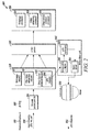
- FIG. 2 is a block diagram of a PTZ camera system 200 in accordance with disclosed embodiments.
- input 205 that includes a p/t/z request can be received via a user input device 210, such as a head-end keyboard, joystick, or the like, of an IP PTZ camera 260 at a network packet port 215 and transmitted to a request module 220.
- the request module 220 can include a webpage request sub-module 221, an http video stream request sub-module 222, and a control protocol request sub-module 223.
- control protocol request sub-module 223 can include a simple text parser to accelerate parsing.
- the text parser in the sub-module 223 can extract and process only PTZ parameters, including the p/t/z request 206 in the input 205.
- the motor driver unit 245 can include a p/t/z/ analyzer 235 and a motor driver 255.
- the motor driver unit 245, including the analyzer 235 and the motor driver 255 can be enclosed in a housing.
- the p/t/z analyzer 235 of the motor driver unit 245 can receive the p/t/z/ request 206 from the control protocol request sub-module 223, extract a p/t/z/ command 240, that is, a pan, tilt, and zoom command, from the request 206, and transmit the p/t/z command 240 to the motor driver 255. Then, the motor driver 255 can transmit the command 240 to a motor 250 of the PTZ camera 260 for producing a response 255 from the PTZ camera 260.
- the p/t/z/ request 206 is processed early, that is, without first passing through a parser 225 and a processor 230, and is instead processed directly in the motor driver unit 245, the latency between receiving the request 206 in the input 205 and the resulting response 255 from the PTZ camera 260 and motor 250 can be reduced.
- the system 200 can be more efficient and respond to user input more quickly.
- known PTZ cameras systems can include a latency of approximately 175-261 ms.
- the resulting latency can be decreased to approximately 160ms.
- systems and methods disclosed herein including the system 200 shown in FIG. 2 , the latency can be reduced to approximately 22ms.
Abstract
Description
- The present invention relates generally to IP PTZ cameras. More particularly, the present invention relates to an apparatus and method to reduce PTZ latency.
- Known PTZ cameras and other video capture devices use a complex communication protocol to facilitate the pan, tilt, and zoom functions of the camera. This can be inefficient. Indeed, when a joystick, keyboard or other input device is used to control the pan, tilt, and zoom functions of the camera, the camera often does not pan, tilt, and/or zoom in a smooth manner and does not respond to the input control in as timely of a manner as is desired. Accordingly, it is difficult to track an object using the pan, tilt, and zoom functions of the camera, causing many users to be dissatisfied with the performance of the camera.
- For example,
FIG. 1 is a block diagram of aPTZ camera system 100 known in the art. As seen inFIG. 1 ,input 105 that includes a p/t/z request can be received via auser input device 110, such as a head-end keyboard, joystick, or the like, of anIP PTZ camera 160 at anetwork packet port 115 and transmitted to arequest module 120. Therequest module 120 can include awebpage request sub-module 121, an http videostream request sub-module 122, and a controlprotocol request sub-module 123. - The
request module 120 can transmit theinput 105, including the p/t/z/ request, to anhttp parser 125. For example, theparser 125 in some known systems includes a parser that employs the Open Network Video Interface Forum (ONVIF) protocol. - The
parser 125 can transmit theinput 105 to aprocessor module 130, and, as seen inFIG. 1 , theprocessor module 130 can include awebpage processor 131, avideo streaming processor 132, and acontrol protocol processor 133. Thecontrol protocol processor 133 can process the receivedinput 105, including the p/t/z request, and transmit the processedinput 105 to asyntax analyzer 135. - The
syntax analyzer 135 can extract a p/t/z command 140, that is, a pan, tilt, and zoom command, from the processedinput 105 and transmit the p/t/z command 140 to amotor driver unit 145, which can then transmit thecommand 140 to amotor 150 of thePTZ camera 160 for producing aresponse 155 from thePTZ camera 160. Accordingly, as seen inFIG. 1 , in known systems, the p/t/z command 140 is not extracted from theinput 105 until after theinput 105 passes through thehttp processor 125 and theprocessor module 130. This contributes to a delayed andlatent response 155 from thePTZ motor 150 andcamera 160 after theinput 105 is received. - In view of the above, there is a continuing, ongoing need for an improved apparatus and method to reduce PTZ latency.
-
-
FIG. 1 is a block diagram of a PTZ camera system known in the art; and -
FIG. 2 is a block diagram of a PTZ camera system in accordance with disclosed embodiments. - While this invention is susceptible of an embodiment in many different forms, there are shown in the drawings and will be described herein in detail specific embodiments thereof with the understanding that the present disclosure is to be considered as an exemplification of the principles of the invention. It is not intended to limit the invention to the specific illustrated embodiments.
- Embodiments disclosed herein include an improved apparatus and method to reduce PTZ latency. For example, in some embodiments, the latency between receiving input with a p/t/z/ request and the resulting response from a PTZ camera and motor can be reduced. Accordingly, a user's experience when operating the PTZ system can be improved.
- The improved apparatus and method to reduce PTZ latency in accordance with embodiments disclosed herein can be implemented in firmware and/or hardware. Additionally or alternatively, in some embodiments, the improved apparatus and method disclosed herein can be implemented with executable control software stored on a transitory or non-transitory computer readable medium, including but not limited to, computer memory, RAM, optical storage media, magnetic storage media, flash memory, and the like.
-
FIG. 2 is a block diagram of aPTZ camera system 200 in accordance with disclosed embodiments. As seen inFIG. 2 ,input 205 that includes a p/t/z request can be received via auser input device 210, such as a head-end keyboard, joystick, or the like, of anIP PTZ camera 260 at anetwork packet port 215 and transmitted to arequest module 220. In some embodiments, therequest module 220 can include awebpage request sub-module 221, an http videostream request sub-module 222, and a controlprotocol request sub-module 223. - Unlike known systems, the control
protocol request sub-module 223 can extract the p/t/z request 206 from theinput 205 and transmit at least the p/t/z/request 206 to amotor driver unit 245 without first passing the p/t/z/request 206 through an http and/orONVIF parser 225 or aprocessor module 230, including awebpage processor 231, avideo streaming processor 232, or acontrol protocol processor 233. - In some embodiments, the control
protocol request sub-module 223 can include a simple text parser to accelerate parsing. For example, the text parser in thesub-module 223 can extract and process only PTZ parameters, including the p/t/z request 206 in theinput 205. - As seen in
FIG. 2 , themotor driver unit 245 can include a p/t/z/analyzer 235 and amotor driver 255. In some embodiments, themotor driver unit 245, including theanalyzer 235 and themotor driver 255 can be enclosed in a housing. - The p/t/
z analyzer 235 of themotor driver unit 245 can receive the p/t/z/request 206 from the controlprotocol request sub-module 223, extract a p/t/z/command 240, that is, a pan, tilt, and zoom command, from therequest 206, and transmit the p/t/z command 240 to themotor driver 255. Then, themotor driver 255 can transmit thecommand 240 to amotor 250 of thePTZ camera 260 for producing aresponse 255 from thePTZ camera 260. Because the p/t/z/request 206 is processed early, that is, without first passing through aparser 225 and aprocessor 230, and is instead processed directly in themotor driver unit 245, the latency between receiving therequest 206 in theinput 205 and the resultingresponse 255 from thePTZ camera 260 andmotor 250 can be reduced. Thus, thesystem 200 can be more efficient and respond to user input more quickly. - When known PTZ camera systems are compared with the systems and methods disclosed herein, substantial reduction in the latency between receiving a p/t/z request and the resulting response from the PTZ camera and motor under test can be observed. For example, known PTZ cameras systems, including the
system 100 shown inFIG. 1 , can include a latency of approximately 175-261 ms. When the performance of the processor and/or the syntax analyzer of known systems is improved, the resulting latency can be decreased to approximately 160ms. However, when systems and methods disclosed herein are employed, including thesystem 200 shown inFIG. 2 , the latency can be reduced to approximately 22ms. - Although a few embodiments have been described in detail above, other modifications are possible. For example, the logic flows described above do not require the particular order described, or sequential order, to achieve desirable results. Other steps may be provided, or steps may be eliminated, from the described flows, and other components may be added to, or removed from, the described systems. Other embodiments may be within the scope of the invention.
- From the foregoing, it will be observed that numerous variations and modifications may be effected without departing from the spirit and scope of the invention. It is to be understood that no limitation with respect to the specific system or method described herein is intended or should be inferred. It is, of course, intended to cover all such modifications as fall within the sprit and scope of the invention.
Claims (15)
- A system comprising:an input port; anda motor driver unit,wherein the input port receives a PTZ request,wherein the input port transmits the PTZ request to the motor driver unit, andwherein the motor driver unit extracts a PTZ command from the PTZ request.
- The system of claim 1 further comprising a request module,
wherein the input port transmits the PTZ request to the motor driver unit via the request module. - The system of claim 1 further comprising at least one of a parser and a processor, wherein the PTZ request obviates transmission through the at least one of the parser and the processor.
- The system of claim 1 wherein the input port receives input that includes the PTZ request.
- The system of claim 4 further comprising control protocol module, wherein the control protocol sub-module extracts the PTZ request from the input.
- The system of claim 1 wherein the motor driver unit includes an analyzer and a motor driver.
- The system of claim 6 wherein the analyzer extracts the PTZ command from the PTZ request and transmits the PTZ command to the motor driver.
- The system of claim 6 wherein the motor driver transmits the PTZ command to a motor of a PTZ camera.
- The system of claim 8 wherein the motor of the PTZ camera executes the PTZ command.
- A motor driver unit comprising:an analyzer; anda motor driver,wherein the analyzer extracts a PTZ command from a received PTZ request and transmits the PTZ command to the motor driver, andwherein the motor driver transmits the PTZ command to a motor of a PTZ camera for execution of the PTZ command.
- The motor driver unit of claim 10 further comprising a housing enclosing the analyzer and the motor driver.
- The motor driver unit of claim 10 wherein the analyzer unit receives the PTZ request from an input port or from a request module of a PTZ camera.
- The motor driver unit of claim 10 wherein the PTZ request obviates transmission through at least one of a parser and a processor before the analyzer receives the PTZ request.
- A method comprising:receiving a PTZ request;extracting a PTZ command from the PTZ request; andobviating transmission of the PTZ request through at least one of a parser and a processor;
- The method of claim 14 wherein receiving the PTZ request includes receiving an input that includes the PTZ request.
Applications Claiming Priority (1)
| Application Number | Priority Date | Filing Date | Title |
|---|---|---|---|
| US13/938,873 US9398203B2 (en) | 2013-07-10 | 2013-07-10 | Apparatus and method to reduce PTZ latency |
Publications (1)
| Publication Number | Publication Date |
|---|---|
| EP2824918A1 true EP2824918A1 (en) | 2015-01-14 |
Family
ID=51022236
Family Applications (1)
| Application Number | Title | Priority Date | Filing Date |
|---|---|---|---|
| EP14173754.4A Ceased EP2824918A1 (en) | 2013-07-10 | 2014-06-24 | Apparatus and method to reduce PTZ latency |
Country Status (5)
| Country | Link |
|---|---|
| US (1) | US9398203B2 (en) |
| EP (1) | EP2824918A1 (en) |
| CN (1) | CN104284087B (en) |
| CA (1) | CA2855659C (en) |
| IN (1) | IN2014DE01770A (en) |
Families Citing this family (2)
| Publication number | Priority date | Publication date | Assignee | Title |
|---|---|---|---|---|
| US10201346B2 (en) * | 2013-08-02 | 2019-02-12 | Covidien Lp | Devices, systems, and methods for providing surgical access and facilitating closure of surgical access openings |
| TWI522760B (en) * | 2015-01-08 | 2016-02-21 | 晶睿通訊股份有限公司 | Motor control method, motor control device and camera |
Citations (4)
| Publication number | Priority date | Publication date | Assignee | Title |
|---|---|---|---|---|
| US5463432A (en) * | 1993-05-24 | 1995-10-31 | Kahn; Philip | Miniature pan/tilt tracking mount |
| US6867798B1 (en) * | 1999-08-31 | 2005-03-15 | Matsushita Electric Industrial Co., Ltd. | Monitor camera system and method of displaying picture from monitor camera thereof |
| US20060136972A1 (en) * | 2003-02-11 | 2006-06-22 | Raymond Metzger | System for a plurality of video cameras disposed on a common network |
| US20130155182A1 (en) * | 2011-12-20 | 2013-06-20 | Motorola Solutions, Inc. | Methods and apparatus to compensate for overshoot of a desired field of vision by a remotely-controlled image capture device |
Family Cites Families (4)
| Publication number | Priority date | Publication date | Assignee | Title |
|---|---|---|---|---|
| US7397346B2 (en) * | 2003-07-10 | 2008-07-08 | University Of Florida Research Foundation, Inc. | Daily task and memory assistance using a mobile device |
| JP4546202B2 (en) * | 2004-09-28 | 2010-09-15 | キヤノン株式会社 | VIDEO RECEIVING DEVICE, ITS CONTROL METHOD, PROGRAM, AND STORAGE MEDIUM |
| US8819178B2 (en) * | 2005-03-16 | 2014-08-26 | Icontrol Networks, Inc. | Controlling data routing in integrated security systems |
| JP4636132B2 (en) * | 2008-07-09 | 2011-02-23 | ソニー株式会社 | Network camera |
-
2013
- 2013-07-10 US US13/938,873 patent/US9398203B2/en active Active
-
2014
- 2014-06-24 EP EP14173754.4A patent/EP2824918A1/en not_active Ceased
- 2014-07-01 IN IN1770DE2014 patent/IN2014DE01770A/en unknown
- 2014-07-02 CA CA2855659A patent/CA2855659C/en not_active Expired - Fee Related
- 2014-07-09 CN CN201410326159.2A patent/CN104284087B/en active Active
Patent Citations (4)
| Publication number | Priority date | Publication date | Assignee | Title |
|---|---|---|---|---|
| US5463432A (en) * | 1993-05-24 | 1995-10-31 | Kahn; Philip | Miniature pan/tilt tracking mount |
| US6867798B1 (en) * | 1999-08-31 | 2005-03-15 | Matsushita Electric Industrial Co., Ltd. | Monitor camera system and method of displaying picture from monitor camera thereof |
| US20060136972A1 (en) * | 2003-02-11 | 2006-06-22 | Raymond Metzger | System for a plurality of video cameras disposed on a common network |
| US20130155182A1 (en) * | 2011-12-20 | 2013-06-20 | Motorola Solutions, Inc. | Methods and apparatus to compensate for overshoot of a desired field of vision by a remotely-controlled image capture device |
Also Published As
| Publication number | Publication date |
|---|---|
| CA2855659C (en) | 2017-10-03 |
| US20150015731A1 (en) | 2015-01-15 |
| CN104284087B (en) | 2018-05-04 |
| US9398203B2 (en) | 2016-07-19 |
| CN104284087A (en) | 2015-01-14 |
| IN2014DE01770A (en) | 2015-06-19 |
| CA2855659A1 (en) | 2015-01-10 |
Similar Documents
| Publication | Publication Date | Title |
|---|---|---|
| EP2922277B1 (en) | Method and device for remote control of a set top box | |
| EP2523145A1 (en) | Method for dynamically adapting video image parameters for facilitating subsequent applications | |
| US20190051147A1 (en) | Remote control method, apparatus, terminal device, and computer readable storage medium | |
| WO2014086223A1 (en) | Video communication method and apparatus | |
| WO2018192372A1 (en) | Method and device for identifying type of text information, storage medium and electronic device | |
| JP7409963B2 (en) | Computing system with trigger feature based on channel change | |
| CN112044055A (en) | Image data acquisition method, system, device, electronic equipment and storage medium | |
| WO2019174044A1 (en) | Image processing method, device and system, and storage medium | |
| CN103686448A (en) | Video transcoding download speed limiting method and system | |
| KR20220115956A (en) | Secure methods, devices, and systems that are easy to access by users | |
| KR102054930B1 (en) | Method and apparatus for sharing picture in the system | |
| WO2018086477A1 (en) | Digital television descrambling method and device | |
| CA2855659C (en) | Apparatus and method to reduce ptz latency | |
| US20170171281A1 (en) | Play method and apparatus and mobile terminal device for android platform | |
| US10721192B2 (en) | Visual media file transmission method and user terminal | |
| CN108933769B (en) | Streaming media screenshot system, method and device | |
| CN113179261B (en) | Video stream processing method and device, storage medium and platform server | |
| CN105791223B (en) | media stream data processing method and system and electronic equipment | |
| EP3042499B1 (en) | Video stream transmission method and system | |
| CN115103204A (en) | Method and device for realizing edge intelligent application supporting AI engine | |
| WO2014101672A1 (en) | Method and apparatus for cotrolling camera devices | |
| KR101612312B1 (en) | DATA processing improvement device and method thereof | |
| CN103685943A (en) | Display equipment, image capturing and controlling device and image capturing and controlling method | |
| CN113760946A (en) | Pre-verification processing method, device, equipment and medium applied to data source migration | |
| KR102126794B1 (en) | Apparatus and Method for Transmitting Video Data |
Legal Events
| Date | Code | Title | Description |
|---|---|---|---|
| 17P | Request for examination filed |
Effective date: 20140624 |
|
| AK | Designated contracting states |
Kind code of ref document: A1 Designated state(s): AL AT BE BG CH CY CZ DE DK EE ES FI FR GB GR HR HU IE IS IT LI LT LU LV MC MK MT NL NO PL PT RO RS SE SI SK SM TR |
|
| AX | Request for extension of the european patent |
Extension state: BA ME |
|
| PUAI | Public reference made under article 153(3) epc to a published international application that has entered the european phase |
Free format text: ORIGINAL CODE: 0009012 |
|
| RAP1 | Party data changed (applicant data changed or rights of an application transferred) |
Owner name: HONEYWELL INTERNATIONAL INC. |
|
| 17Q | First examination report despatched |
Effective date: 20160531 |
|
| STAA | Information on the status of an ep patent application or granted ep patent |
Free format text: STATUS: THE APPLICATION HAS BEEN REFUSED |
|
| 18R | Application refused |
Effective date: 20181207 |