EP2843281A1 - Diagnostic method for detecting control valve component failure - Google Patents
Diagnostic method for detecting control valve component failure Download PDFInfo
- Publication number
- EP2843281A1 EP2843281A1 EP14186841.4A EP14186841A EP2843281A1 EP 2843281 A1 EP2843281 A1 EP 2843281A1 EP 14186841 A EP14186841 A EP 14186841A EP 2843281 A1 EP2843281 A1 EP 2843281A1
- Authority
- EP
- European Patent Office
- Prior art keywords
- actuator
- control valve
- valve
- flow switch
- pressure
- Prior art date
- Legal status (The legal status is an assumption and is not a legal conclusion. Google has not performed a legal analysis and makes no representation as to the accuracy of the status listed.)
- Granted
Links
- 238000002405 diagnostic procedure Methods 0.000 title 1
- 238000000034 method Methods 0.000 claims abstract description 95
- 238000013022 venting Methods 0.000 claims abstract description 21
- 230000008569 process Effects 0.000 claims description 72
- 238000001514 detection method Methods 0.000 claims description 65
- 238000004886 process control Methods 0.000 claims description 33
- 239000012530 fluid Substances 0.000 claims description 15
- 238000004891 communication Methods 0.000 claims description 12
- 230000008859 change Effects 0.000 description 38
- 230000006866 deterioration Effects 0.000 description 37
- 239000007789 gas Substances 0.000 description 26
- 238000012856 packing Methods 0.000 description 19
- 238000012544 monitoring process Methods 0.000 description 15
- 230000002159 abnormal effect Effects 0.000 description 14
- 238000012423 maintenance Methods 0.000 description 14
- 230000002265 prevention Effects 0.000 description 10
- 230000006870 function Effects 0.000 description 8
- 238000012545 processing Methods 0.000 description 8
- 230000015556 catabolic process Effects 0.000 description 7
- 238000006731 degradation reaction Methods 0.000 description 7
- 230000004044 response Effects 0.000 description 7
- 230000007797 corrosion Effects 0.000 description 4
- 238000005260 corrosion Methods 0.000 description 4
- 230000007423 decrease Effects 0.000 description 4
- 230000007547 defect Effects 0.000 description 4
- 230000000694 effects Effects 0.000 description 4
- 238000005070 sampling Methods 0.000 description 4
- 230000001010 compromised effect Effects 0.000 description 3
- 238000013480 data collection Methods 0.000 description 3
- 230000002950 deficient Effects 0.000 description 3
- 238000005259 measurement Methods 0.000 description 3
- 230000000737 periodic effect Effects 0.000 description 3
- 238000013459 approach Methods 0.000 description 2
- 230000004888 barrier function Effects 0.000 description 2
- 230000008901 benefit Effects 0.000 description 2
- 238000004364 calculation method Methods 0.000 description 2
- 238000010276 construction Methods 0.000 description 2
- 230000008878 coupling Effects 0.000 description 2
- 238000010168 coupling process Methods 0.000 description 2
- 238000005859 coupling reaction Methods 0.000 description 2
- 238000013461 design Methods 0.000 description 2
- 230000002542 deteriorative effect Effects 0.000 description 2
- 238000005516 engineering process Methods 0.000 description 2
- 231100001261 hazardous Toxicity 0.000 description 2
- 238000009434 installation Methods 0.000 description 2
- 230000007257 malfunction Effects 0.000 description 2
- 150000003839 salts Chemical class 0.000 description 2
- 238000007789 sealing Methods 0.000 description 2
- 238000012369 In process control Methods 0.000 description 1
- 230000009471 action Effects 0.000 description 1
- 238000013528 artificial neural network Methods 0.000 description 1
- 230000033228 biological regulation Effects 0.000 description 1
- 230000006835 compression Effects 0.000 description 1
- 238000007906 compression Methods 0.000 description 1
- 230000007123 defense Effects 0.000 description 1
- 230000003111 delayed effect Effects 0.000 description 1
- 230000003467 diminishing effect Effects 0.000 description 1
- 230000003628 erosive effect Effects 0.000 description 1
- 239000000383 hazardous chemical Substances 0.000 description 1
- 238000010965 in-process control Methods 0.000 description 1
- 238000010348 incorporation Methods 0.000 description 1
- 239000011261 inert gas Substances 0.000 description 1
- 238000004519 manufacturing process Methods 0.000 description 1
- 239000000463 material Substances 0.000 description 1
- 238000010338 mechanical breakdown Methods 0.000 description 1
- 230000007246 mechanism Effects 0.000 description 1
- 239000002184 metal Substances 0.000 description 1
- 238000012986 modification Methods 0.000 description 1
- 230000004048 modification Effects 0.000 description 1
- 230000003647 oxidation Effects 0.000 description 1
- 238000007254 oxidation reaction Methods 0.000 description 1
- 230000037361 pathway Effects 0.000 description 1
- 230000009467 reduction Effects 0.000 description 1
- 230000008439 repair process Effects 0.000 description 1
- 238000012552 review Methods 0.000 description 1
- 230000001360 synchronised effect Effects 0.000 description 1
- 231100000331 toxic Toxicity 0.000 description 1
- 230000002588 toxic effect Effects 0.000 description 1
- 238000012549 training Methods 0.000 description 1
Images


Classifications
-
- F—MECHANICAL ENGINEERING; LIGHTING; HEATING; WEAPONS; BLASTING
- F16—ENGINEERING ELEMENTS AND UNITS; GENERAL MEASURES FOR PRODUCING AND MAINTAINING EFFECTIVE FUNCTIONING OF MACHINES OR INSTALLATIONS; THERMAL INSULATION IN GENERAL
- F16K—VALVES; TAPS; COCKS; ACTUATING-FLOATS; DEVICES FOR VENTING OR AERATING
- F16K37/00—Special means in or on valves or other cut-off apparatus for indicating or recording operation thereof, or for enabling an alarm to be given
- F16K37/0075—For recording or indicating the functioning of a valve in combination with test equipment
- F16K37/0091—For recording or indicating the functioning of a valve in combination with test equipment by measuring fluid parameters
-
- F—MECHANICAL ENGINEERING; LIGHTING; HEATING; WEAPONS; BLASTING
- F16—ENGINEERING ELEMENTS AND UNITS; GENERAL MEASURES FOR PRODUCING AND MAINTAINING EFFECTIVE FUNCTIONING OF MACHINES OR INSTALLATIONS; THERMAL INSULATION IN GENERAL
- F16K—VALVES; TAPS; COCKS; ACTUATING-FLOATS; DEVICES FOR VENTING OR AERATING
- F16K37/00—Special means in or on valves or other cut-off apparatus for indicating or recording operation thereof, or for enabling an alarm to be given
- F16K37/0075—For recording or indicating the functioning of a valve in combination with test equipment
- F16K37/0083—For recording or indicating the functioning of a valve in combination with test equipment by measuring valve parameters
-
- G—PHYSICS
- G01—MEASURING; TESTING
- G01M—TESTING STATIC OR DYNAMIC BALANCE OF MACHINES OR STRUCTURES; TESTING OF STRUCTURES OR APPARATUS, NOT OTHERWISE PROVIDED FOR
- G01M3/00—Investigating fluid-tightness of structures
Definitions
- This patent relates generally to performing diagnostics and maintenance in a process plant and, more particularly, to providing diagnostic capabilities within a process plant in a manner that reduces or prevents control valve failures within the process plant.
- control valve failures may impact the response of the control valve to control signals.
- a control valve may become less-responsive or sluggish to a control signal, which may lead to degradation in control performance that induces process variability, which is costly to the plant operators or worse, may lead to hazardous conditions.
- early detection of control valve degradation or deterioration may allow for orderly scheduled maintenance of a control valve in a manner that would prevent disruption of operation to a process plant.
- Control valve performance degradation may occur for a number of reasons. Generally, deterioration of component parts may be a primary factor. Deterioration of parts, however, is typically detected only upon degradation of control valve operation to the point where the control valve malfunctions, due to, for example, a component failure, at which point it may be too late to perform preventative maintenance.
- One approach to preventative maintenance may be to physically inspect the components of a control valve on a periodic basis. This option, however, is costly as it requires that the process control loop using the control valve be shut down and/or that the control valve be removed and disassembled for review.
- a claimed method and system identifies faults and/or deterioration of components in a process control valve. In some embodiments, the claimed method and system detects deterioration and/or faults of actuator springs, pneumatic tubing and piping, and bellows seals.
- actuator spring deterioration or fault in a pneumatic control valve may be detected by monitoring an actuator pressure and actuator rod movement.
- a bellows deterioration or fault in a control valve may be detected by monitoring a bellows chamber pressure and valve movement.
- a source of an actuator leak may be identified.
- a leak in one of instrument tubing or a diaphragm may be detected.
- FIG. 1 illustrates a control valve assembly 10 that may be used in a process control system, e.g., a processing plant.
- the control valve assembly 10 includes a valve 12, an actuator 22, and a control valve instrument or positioner 34.
- the valve 12 includes a valve body 14, an inlet port 16, an outlet port 18, and the actuator 22 includes a valve bonnet 20 and pneumatic diaphragm casing 40. Disposed through the valve bonnet 20 may be a valve stem 32 that may be used to operate the valve 12.
- a yoke 30 may be attached to or provided with the bonnet 20. While the yoke 30 may be connected to the valve bonnet 20, as illustrated in Figure 1 , the yoke 30 may be mounted to another part of the valve body 14 in other embodiments.
- the yoke 30 may be used to couple the pneumatic diaphragm casing 40 to the valve body 14.
- the valve stem 32 which may form a portion of a valve stem assembly 15, described further below, may be adapted to transmit force from the pneumatic diaphragm casing 40 to the valve 12, thereby controlling operation of the valve 12.
- the pneumatic positioner 34 may be attached to the yoke 30.
- the positioner 34 may be used to control the actuator 22.
- positioners such as positioner 34 may be electro-pneumatic and may be used in process control loops to operate control valve assembly 10 in a proscribed manner. That is, the positioner 34 may operate by receiving an electronic input signal at an I/P (current to pressure) stage (components not shown) to convert the electronic input signal to a pneumatic output signal, which may drive the actuator 22.
- the output pressure signal may be applied directly to the pneumatic diaphragm casing, which in turn couples the pneumatic signal to the valve to control flow in a manner proportional to the electronic input signal.
- Figure 2 illustrates a cross-sectional view of the control valve assembly 10 of Figure 1 . Note that analogous members are labeled similarly.
- Figure 2 illustrates the valve body 14 defining the inlet port 16, the outlet port 18, and a passageway 11 communicating between the inlet port 16 and outlet port 18.
- a valve seat 13 may be disposed within the valve body 14 through which the passageway 11 passes.
- a valve stem assembly 15 may consist of a valve plug 17 disposed in the passageway and movable relative to the valve seat 13, thereby controlling fluid flow through the valve body 14.
- the valve stem assembly 15 further includes a valve stem 32 coupled to the valve plug 17 and extending through a bore 19 (e.g., a valve body opening) in the valve bonnet 20.
- valve stem assembly 15 When the valve stem assembly 15 is lifted to open a port between the valve plug 17 and the valve seat 13, flow of fluid through the passageway 11 increases. Lowering the valve stem assembly 15 will close the port and decrease fluid flow until the valve plug 17 completely engages the valve seat 13 (as illustrated in Figure 2 ), thereby preventing any further fluid flow through the passageway 11.
- the valve stem assembly 15 may be coupled to an actuator 22 for raising and lowering the valve stem assembly 15.
- the actuator 22 may include a diaphragm casing 40 that houses diaphragm 36 which is coupled to an actuator rod 35.
- the diaphragm 36 may be biased by a set of (i.e., one or more) actuator springs 37. While the embodiment of Figure 2 illustrates that the diaphragm 36 may be coupled to the actuator rod 35 via a disk 38 and a bolt 39, other fastening means known in the art may be used as well.
- the valve stem 32 may be coupled to an actuator rod 35 by a valve stem connector 33.
- the actuator 22 may be operated to raise or lower the actuator rod 35 and consequently raise or lower the valve stem assembly 15.
- the diaphragm casing 40 of actuator 22 may be supported and positioned over the valve body 12 by the yoke 30.
- the actuator 22 may be a pneumatic actuator that is controlled by the positioner 34.
- the positioner 34 may have a fluid pressure source inlet port 42 that accepts pressurized gas from a fluid source (not shown).
- the positioner 34 may have an outlet port 43 that is fluidly coupled to an inlet port 44 of the actuator diaphragm casing 22.
- the actuator diaphragm casing may have an outlet vent 45 for venting the non-pressurized side of the diaphragm casing 40. While the embodiment of Figure 2 illustrates that the vent outlet port 45 may be coupled to the positioner 34, it may be common that vent 45 is open to ambient atmosphere.
- the positioner 34 may generally operate to control the amount and timing of applied gas to the diaphragm casing 40 from a pressurized source, such as a compressed air source (not shown).
- a pressurized source such as a compressed air source (not shown).
- the pressure in the actuator chamber e.g., chamber 46
- the volume of a lower chamber 47 may source or sink fluid through outlet port 45.
- Figure 2 illustrates a pneumatic actuator embodiment employing a plurality of springs 37
- some pneumatic actuators may use only a single spring.
- Such embodiments may be illustrated in Figures 3A and 3B .
- a single spring 48 and 49 is used to bias a diaphragm 51 and 53, respectively.
- Figure 3A illustrates a direct-acting configuration in which the spring 48 biases the actuator rod 55 for a push-down-to-close construction valve
- Figure 3B illustrates a reverse-acting configuration in which the spring 49 biases the actuator rod 57 for a push-down-to-open construction valve.
- the described system herein assists in determining the cause of valve performance degradation by identifying control valve components in a deteriorating state.
- various sensor readings may be used with algorithms described herein to determine and identify control valve components that may be in poor condition or that may be operating outside an expected performance range. That is, the system may enable early detection of component deterioration before critical malfunction of the control valve.
- the system may monitor control valve function deterioration due to components such as actuator springs, pneumatic tubing and piping, and/or bellow seals.
- actuator response may be negatively affected by deterioration in actuator springs used to bias the actuator.
- Actuator response may be further affected by leaks in pneumatic pathways (e.g., tubes and pipes to and from pneumatic outlets and inlets) or partial or total failure of an actuator diaphragm.
- control valve response may suffer from deterioration in bellows seals that are used to isolate the control valve process environment from an external atmosphere (e.g., an environment surrounding a control valve).
- the system described herein may be used to detect or predict deterioration in one or more of the described components.
- Spring failure is one failure mode that may cause a reduction in response time (i.e., sluggishness) of a control valve. Deterioration of the single spring in actuators such as those illustrated in Figures 3A and 3B may cause instant failure. In a multi-spring actuator, failure of a single spring may not cause an immediate control valve failure or loss of control. However, failure of even a single spring in a multi-spring actuator may result in uneven loading of an actuator that may reduceactuator thrust which could limit operating range of the valve or decrease seat load, thereby increasing seat leakage within the valve. Also, failure of a single spring may indicate that other springs may fail soon.
- spring deterioration may occur due to a number of factors such as erosion or oxidation of the spring, or structural/mechanical breakdown such as fatigue. Either of these conditions may cause the spring to exhibit diminishing elasticity among other physical parameters of the spring.
- An actuator spring deterioration detection system as described herein may be implemented to predict or detect spring deterioration or failure so that preventative measures may be taken to reduce maintenance costs and costly plant shutdowns.
- the spring deterioration detection system may be implemented in an existing process control system or installed as an independently functioning computing unit. Generally, the spring deterioration detection system may be implemented as hardware or software running on a computing device.
- calculating and monitoring a current value of an actuator spring constant may be used to detect spring deterioration.
- a spring constant may be calculated and compared to an initial or designated spring constant value. If the calculated spring constant deviates from the initial or designated value by more than a predetermined threshold, spring deterioration or failure may be detected.
- actuator pressure and valve travel may be monitored and measured to calculate the spring constant value. The following formula may be used to calculate the spring constant value:
- ⁇ T valve travel distance
- ⁇ P a change in applied pressure to an actuator
- A is an effective diaphragm area for a diaphragm of the actuator
- K a is the spring constant
- Figure 4A illustrates an embodiment of a control valve that may be used to determine spring deterioration in an actuator.
- a position sensor 401 may provide data on the position, movement, and/or travel of a control valve assembly 10. The travel of the valve 12 may be based on the movement of the actuator rod 35.
- the actuator rod 35 may be operatively coupled to the valve stem 32, valve stem connector 33, and valve plug 17. Thus, measuring travel of any one of this set of components may be indicative of travel of any member of the set of components.
- a pressure sensor 403 may provide data indicative of a pressure applied to the upper pressure chamber 46.
- a device 405 may be used to receive sensor data from one or both of the travel sensor 401 or the pressure sensor 403. The device 405 may then implement an algorithm, as further discussed below, to detect and indicate a spring fault. While the device 405 in Figure 4A is shown separately from the positioner 34, device 405 may be implemented as part of the positioner 34. This may be the case, for example, when the positioner 34 is a digital positioner having a processor and memory.
- Figure 4B illustrates a process embodiment for detecting actuator spring deterioration.
- a travel of the valve e.g., travel of the actuator rod 35, connector 33, or valve stem 32
- the position of the valve may be sampled on a periodic basis and travel may be determined based on the difference between two sampled positions.
- an applied pressure may be sensed.
- a change in applied pressure may be sensed by periodically sampling the applied pressure and taking the difference between two sampled readings.
- the period for sampling the positions and applied pressure may be synchronized. In other words, both a position and applied pressure sample may be taken at the same time over a common period.
- a current spring constant of the actuator spring may be determined. For example, at a particular period of time, a valve travel distance may be measured with a corresponding pressure change. In an embodiment, a first position of the valve at a first time may be recorded and a second position of the valve at a second time may be recorded, where the difference between the first position and second position may be calculated as the valve travel distance ⁇ T . During the valve travel, a corresponding change in applied actuator pressure may occur. This actuator pressure change may be measured by recording the actuator pressure at the first time when the valve is in the first position and then recording the actuator pressure at the second time when the valve reaches the second position. The difference in the two pressure readings may then be used as the change in pressure ⁇ P.
- a difference between the calculated current spring value constant may be compared to an initial spring value constant. If the current and initial spring value constants differ by more than a predetermined threshold, then a spring failure or spring deterioration indication may be generated 415. If the difference between current and initial spring value constants does not exceed the threshold, then the process may be repeated.
- the initial spring value constant may be provided (e.g., by a manufacturer) or blocks 410-413 may be used to determine the initial spring constant.
- the threshold may be set to a level based on useful life of the actuator spring or plurality of actuator springs. For example, the threshold may be set to a level indicating that the spring has deteriorated to a point where the spring may have just enough useful life to maintain the valve till a replacement spring(s) may be scheduled and/or installed.
- valve travel ⁇ T may be calculated only for a single continuous movement of the valve in one direction.
- valve travel may only be taken as the travel distance when the valve travels from a first position to a second position continuously without changing direction while traveling between the two positions.
- movement between end points e.g., where valve travel is physically restricted
- the actuator may include a plurality of springs. This is illustrated in Figure 2 .
- the spring constant may be an aggregate spring constant to represent the effects of the plurality of springs.
- failure of a single spring may be detected by setting the threshold appropriately.
- the threshold may be based on the number of springs and the average contribution of each spring to the aggregate spring constant.
- the threshold may be set to correspond to a difference in the aggregate spring constant if one of the springs in the plurality of springs is removed (e.g., complete failure).
- the threshold may be set to reflect the difference in the aggregate spring constant if one or more of the springs deteriorates to a minimum functionality but before complete failure of any one spring.
- the threshold may be set based on the number of springs required to overcome friction and hysteresis of the valve during operation. In this embodiment, the threshold may be set so that the system may indicate a spring problem before valve performance is reduced or compromised.
- K 1 represents the spring constant of a first spring of the plurality of springs.
- Figure 5A illustrates a control valve using a bellows seal.
- a bellows 501 may be used as a barrier to isolate ambient plant atmosphere 505 from a process control fluid environment 503.
- the bellows 501 may be necessary in hazardous or toxic process control applications, where containment of hazardous chemicals from the ambient plant environment is required (e.g., see Occupational Safety and Hazard Administration (OSHA) Regulations).
- OSHA Occupational Safety and Hazard Administration
- a bellows is a flexible one-piece, collapsible, seamless device that has deep folds formed from very thin-walled tubing and may be metallic.
- the flexibility of the folds of the bellows may be similar in character to that of a helical coiled compression spring.
- the bellows 501 may be secured to a first portion 513 of valve stem 509 using a bellows gasket 511 at a first end 514 of the bellows.
- a second end 516 of the bellows 501 may be secured to a portion 518 of the valve body 14.
- the valve body portion 518 may be part of the valve bonnet 20.
- the bellows 501 may isolate the control fluid inside the control valve (e.g., in 503) from surrounding atmosphere 505 external to the control valve, while also allowing the valve stem 509 to move freely without much friction.
- the diameter and number of folds of a bellows is generally sized to fit between a valve stem and a valve stem chamber, but varies depending on the arrangement and type of the control valve.
- the bellows 501 may fail in an unpredictable and catastrophic manner from fatigue (e.g., metal fatigue) and/or corrosion. Because of the potential for failure, a packing member 515 may also be implemented in the control valve as a backup sealing structure. Bellows sealed valves usually implement an additional packing member 515 or sealing at a second portion of the valve stem 517 near the top of the valve stem. The second portion of the valve stem may be movable about a valve body opening. The packing 515 may act as a final defense against leaking through the valve stem 509 to atmosphere in case of rupture of the bellows 501.
- Pressure sensors are generally used to indicate level and flow signals.
- a digital positioner may be coupled to a pressure sensor for detecting applied actuator pressure. These pressure sensors may be used to provide control feedback.
- Pressure transmitters may be further used in control valves to detect low pressure in the actuator couplings or valve couplings. However, this low pressure reading alone may not provide information to distinguish bellows leakage from affects of valve stroking or from affects of temperature on the gas trapped between the bellows and the packing, which affects control valve movement.
- Figure 5A illustrates a control valve 507 adapted to detect a bellow seals deterioration or failure.
- Figure 5A illustrates a pressure sensor 520 that may sense the pressure of fluid between the packing 515 and the bellows 501, where the space between the bellows 501 and the packing 515 may form a chamber 530.
- a second sensor 532 may sense valve travel.
- the two sensors i.e., the bellows chamber pressure sensor 520 and the travel sensor 532
- the positioner 534 may then apply an algorithm (further discussed below) to determine a potential bellows failure.
- sensor 532 may be integrated into positioner 534.
- a bellows failure may be indicated when the following conditions are determined:
- P may be the pressure in chamber A
- V may be the volume in chamber A
- n may be the moles of gas in chamber A
- R may be the ideal gas constant
- T may be the absolute temperature.
- the bellows 501 functions and bellows gasket 511 adequately seals chamber 530 from process fluid (e.g., fluid in section 503 of the control valve)
- the volume in chamber 530 should be affected only by valve travel.
- pressure and travel should be inversely proportional.
- pressure and travel should be inversely proportional by the product, nRT.
- the bellows 509 leaks or ruptures
- the relationship between pressure and volume of chamber 530 may be distorted.
- the conditions listed above may be indicative of the relationship between pressure and volume of chamber 530 upon leakage or rupture.
- Figure 5B illustrates a process or algorithm embodiment for detecting a bellows or bellows gasket or seal failure in a control valve.
- travel or movement of a valve stem may be sensed or measured.
- the position of the valve stem may be sampled on a periodic basis and travel may be determined based on the difference between two sampled positions.
- a change in pressure of the bellows chamber may be sensed.
- a change in bellows chamber pressure may be sensed by periodically sampling the chamber pressure and taking the difference between two sampled readings.
- the period for sampling the valve stem position and the bellows chamber pressure may be synched. In other words, both a position and applied pressure sample may be taken at the same time over a common period.
- valve stem it may be determined whether or not the valve stem is moving. If there is no valve stem movement, then it may be determined if there is a bellows chamber pressure change 544. In one embodiment, the change in pressure may be determined during the same period for which the valve stem was sensed to be still. If there is no valve stem movement 543 (i.e., the valve stem was still) and no pressure change 544, then the process may repeat from block 541. If the valve stem is still 543, and there is a pressure change, then a bellows failure indication may be generated 546.
- determining whether there is a corresponding pressure change at conditional block 545 may involve determining if the travel distance of the valve is inversely proportional to the change in bellows chamber pressure. Block 545 may further comprise determining if the travel distance of the valve is inversely proportional to the change in bellows chamber pressure by the product nRT.
- an optional process may be implemented as follows. If the valve stem is not moving for a number of cycles at block 543 (e.g., for a number of consecutive times in which block 543 detects no stem movement), then block 544 may monitor for bellows chamber pressure change over a longer period of time. In this embodiment, monitoring for a slow pressure decay in chamber 530 may be used to detect deterioration of the backup stem packing or a leak in the bellows gasket. When slow pressure decay is detected, a packing or gasket failure indicator may be generated. In one embodiment the valve stem may be still as a consequence of the control valve process (e.g., a long open or close period).
- valve stem may be intentionally stopped for a period of time to determine if there is a drop in pressure of chamber 530.
- the monitoring of slow pressure decay may be implemented as a separate process that is executed contemporaneously with the process of Figure 5B .
- Figure 5B illustrates a particular order of the blocks, the blocks may be sequentially rearranged and remain within the scope of this disclosure. For example, instead of checking valve stem movement first, pressure change in the bellows chamber may be checked first.
- Positioner 534 may receive inputs from position sensor 532 and pressure sensor 520.
- Positioner 534 may include computing capabilities.
- positioner may include a computing device (e.g., a digital positioner) having a processor and memory and may be adapted to execute program instructions (e.g., store in the memory) to implement the process of Figure 5B .
- program instructions e.g., store in the memory
- Figure 5A illustrates that the detection process or algorithm may be implemented in a positioner, a computing device separate and distinct from a valve positioner may be used in other embodiments to collect or receive the sensor data from the two sensors 520 and 532, and apply the algorithm described herein to determine bellows failure.
- inert gas may be injected into the chamber A to insure safe operation of the control valve until maintenance may be performed.
- Actuator leaks contribute to control valve performance degradation, and two potential leak areas may be leaks in instrument air tubing for the pneumatic actuator and compromised actuator diaphragms.
- Pressure sensors may be used to detect an applied pressure to a pneumatic actuator and data from the pressure sensors may show abnormal pressure function (e.g., excess gas flow through the actuator), thereby indicating a leak in the actuator.
- abnormal pressure function e.g., excess gas flow through the actuator
- the cause or location of this actuator leak may not be easily identified.
- monitoring applied actuator pressure alone may not provide information to identify a leaky actuator component.
- an algorithm may be used to determine and identify the cause of control valve performance degradation due to actuator component leaks.
- FIG. 6A illustrates an embodiment of a control valve adapted to identify leaks in a set of pneumatic actuator components.
- a positioner 34 may be a digital positioner that includes a computing device for operating the positioner and for executing a detection algorithm (as further described below).
- a flow switch 91 may be installed on the actuator vent 45 and wired to the positioner 34.
- the actuator vent 45 may be coupled to an inlet port 92 of the flow switch 91 while an outlet port 93 of the flow switch 91 is open to ambient atmosphere.
- a flow switch senses differential pressure between an inlet and outlet of the flow switch and actuates an electrical switch at a predetermined flow level.
- the flow switch 91 may be a commercially available flow switch.
- the flow switch 91 may be a passive device that does not require an external power source to operate.
- the flow switch 91 may be attached to the actuator vent 45 to indicate when the actuator vent is exhausting gas.
- the positioner may include diagnostics for monitoring the pressure in the actuator chamber. For example, similar to the actuator spring embodiment described above, a pressure sensor may sense the applied pressure to the actuator and provide readings to the digital positioner. As discussed, the digital positioner may detect that some kind of leak exists when, for example, actuator pressure drops below a threshold. However, sensing a general actuator pressure drop alone (e.g., in a chamber of the diaphragm casing) may not provide information to identify a cause of the leak.
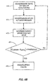
- FIG. 6B illustrates a leak detection algorithm or process.
- a drop in actuator pressure may generate an actuator leak indication.
- the diaphragm flow switch may be polled 601 to determine a flow condition. If the flow switch indicates that gas is being exhausted through the actuator vent at block 602, an instrument tubing leak may exist. When this condition exists, the digital positioner or detection device may generate an indication of a tubing leak 603. If the flow switch indicates that gas is not being exhausted through the actuator vent at block 602, then block 604 may determine whether the valve stem is moving.
- Valve stem movement may be determined by existing valve stem travel or position sensors that sense the position/movement of the valve and actuator stem. Valve stem movement generally causes exhaust venting. Thus, if the valve stem is moving, then the cause of the leak may be indeterminate. In this case, the process may wait a period 605 before polling the flow switch 601 again and repeating the above process blocks. If it is determined that the valve stem is not moving at 604 when the flow switch indicates venting at block 602, then a diaphragm failure may exist. In this case, an indication of a defective diaphragm or an indication of a diaphragm failure may be generated 606.
- the flow switch may be a commercially available passive flow switch.
- the flow switch may be a Gentech FCS-04 or Malema M-60/M064 switch.
- Different implementations of the flow switch may have either a closed switch position or an open switch position correspond to an open or closed vent.
- the algorithm above may be configured appropriately to match the switch polarity.
- FIG. 7 illustrates that a vent 59 of the positioner 34 is fluidly coupled to a vent 45 of the diaphragm casing 40. In this configuration, when the positioner 34 is applying a pressure to the diaphragm 36, gas may be forced out of the actuator vent 45 by the downward movement of the diaphragm 36 and diaphragm plate 37.
- Figure 8 illustrates an embodiment of the leak detection system using a modified double acting positioner 83 that builds on the principles illustrated in Figure 7 .
- a typical double actuating positioner two supply outlets may be provided for supplying compressed air to the actuator, where each supply outlet may be controlled by a designated pneumatic relay, such as relay 84.
- relay 84 When the double actuating positioner is installed in a diaphragm actuator that only requires a single compressed air supply, e.g., actuator 85, then the second relay may be replaced with a flow meter 86. In this case, an actuator vent 87 may be connected back to the modified positioner 83 to the flow switch 86.
- the actuator vent 87 may then be coupled to the positioner vent 88 via the flow switch 86 (internal connecting passageway not shown), to produce a similar effect to that of Figure 7 .
- a control valve may be easily adapted to implement the diagnostics process described above with the corrosion protection from a coupled vent configuration.
- modification of a double acting positioner for installation into a diaphragm and spring actuator may provide an economical incorporation of the diagnostic design described herein and also provide a more appealing package.
- the flow switch 86 now disposed within the positioner 83 itself, may be more easily integrated or connected to the positioner circuitry.
- the benefit of detection and identification of defective tubing or defective actuator diaphragm is the difference in cost to remedy one defect from the other.
- a tubing leak may be remedied simply in the field in a short period using readily available materials and may not require the valve to be removed from service or taken offline.
- the remedy may simply involve tightening fittings.
- a diaphragm failure may require spare parts that may not be available and may take a significantly longer period to fix.
- a diaphragm failure may require the control valve to be taken offline while the actuator is taken apart.
- the above processes or algorithms may be implemented in computing devices for detecting deterioration of a valve component and/or identifying a component fault during operation of the control valve.
- the deterioration detection algorithm may be implemented in a detection module.
- detection module is used herein to refer to any type of block or element that collects data, such as sensor data, and performs some processing on this data to determine an event, such as a defect or failure event as described above.
- this term is intended to cover software, firmware, hardware and/or other elements that perform this function, whether these elements are in the form of function blocks, or other types of blocks, programs, routines or elements.
- Figure 9 illustrates a computing device that may be used to implement a detection algorithm.
- Components of computing device 50 may include, but are not limited to, a processing unit 52, a system memory 54, and a system bus 56 that couples various system components to the processing unit 52.
- Memory 54 may be any available media that is accessible by the processing unit 52 and includes both volatile and nonvolatile media, removable and non-removable media.
- a user may enter commands and information into the computing device 50 through user input devices 66, such as a keyboard and a pointing device. These and other input devices may be connected to the processing unit 52 through a user input interface 60 that may be coupled to the system bus 56.
- a monitor or other type of display device may also be connected to the processor 52 via the user interface 60.
- Other interface and bus structures may also be used.
- inputs 62 from other devices may be received at the computing device 50 via input/output (I/O) interface 58 and outputs 64 from computing device 120 may be provided by the input/output (I/O) interface 58 to other devices.
- the interfaces 58 and 60 connect various devices to the processor 52 via the system bus 56.
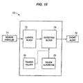
- Figure 10 illustrates a detection module 70 that may be implemented on the computing device 50 of Figure 9 .
- the detection module 70 illustrated in Figure 10 may be used to implement an algorithm for detecting actuator spring deterioration in a pneumatic control valve by receiving an input such as the change in pressure applied to an actuator and a valve travel distance.
- a logical block 72 may receive a set of (i.e., one or more) sensor/measurement signals 74 and may calculate parameters for the set of process signals 74 (e.g., differentials, averages, etc.).
- the calculated parameter(s) may be received by a detection block 76 which operates in accordance with rules contained in a rules block 78.
- the rules block 78 may be implemented, for example, in a portion of the memory 54 of computing device 50 ( Figure 9 ) and may define an algorithm for detecting a deteriorating or faulty component, as further discussed below.
- a first set of calculated parameters may be stored in trained value block 80.
- the trained values may be calculated and periodically updated, for example, by the computing device 50.
- the trained values may be generated by the logical block 72 which generates, or learns, the nominal or normal parameters during a first period of operation, typically a period during normal operation of the process or during a configuration phase. These nominal parameters may then be stored as trained values in the trained values block 80 for future use. This operation allows dynamic adjustment of trained values 80 for a specific operating condition. In this situation, parameters (which may be used for the trained values) may be monitored for a user selectable period of time based upon the process or operating situation.
- a computing device such as the computing device 50 may generate or receive the trained values or be used to transmit the trained values to another process device.
- the rules block 78 may contain rules for detecting or identifying a component fault as described above.
- rules block 78 may contain program instructions that implement one or more of the processes described above for determining a component fault.
- the detection block 76 may be programmed to output an alert 82 when a fault event is detected.
- a statistical process monitoring approach may be implemented to further refine the one ore more of the deterioration detection algorithms described above.
- the logical block 72 may determine a baseline mean ( ⁇ ) and a baseline standard deviation ( ⁇ ) of the change in actuator pressure ( ⁇ P) for a given actuator rod travel distance ( ⁇ T ) during an initial configuration or learning period. These parameters may be considered a representation of the process in a "normal" condition.
- the baseline mean and baseline standard deviation may then be stored in the memory 54 as training values (i.e., using block 80).
- the module 70 implementing the algorithm, may take current values of the pressure change and calculate the process mean ( x ) and standard deviation (s) of the pressure change for a given change in valve travel (or vice versa).
- spring deterioration may be detected at the detection block 76 if the actual or current mean differs from the baseline mean by more than some threshold and an indication or an alarm 82 may be outputted.
- spring failure may be detected if the current mean is more than a certain percent below the baseline mean: x ⁇ ⁇ 1 - ⁇ 100 ⁇ ⁇
- the detection module 70 may include an input for a detection threshold (e.g., one determined by a user). In this embodiment, the detection threshold may be stored as a trained value.
- the threshold may be set based on a variance observed during the learning phase. For example, spring fault may be detected if x ⁇ ⁇ - 3 ⁇ .
- the observed variance may be stored in the memory 54 via the trained value block 80.
- the detection threshold is determined automatically, and the amount of manual configuration may be reduced. It should be noted that any other multiplier for the standard deviation besides three may be used, depending on the observed or detected variance.
- the variance variable may be automatically calculated by the detection module, this variable may be a user-configurable parameter input as a trained variable (e.g., via user I/O 66).
- an initial spring constant value may be given (e.g., provided by a manufacturer for a particular pneumatic control valve) and this initial spring constant may be stored as a trained value without computing or verifying an initial spring constant.
- predetermined thresholds for the algorithms may be stored in trained values block 80.
- SPM may be applied to the bellows leak detection algorithm, where the logical block 72 may determine a baseline mean ( ⁇ ) and a baseline standard deviation ( ⁇ ) of the change in bellows chamber pressure for a given valve stem movement (or vice versa) during an initial period.
- the detection module 70 implementing the algorithm, may take current values of the pressure change and valve stem travel and calculate the process mean ( x ) and standard deviation (s) of one variable against a change in the other. When the difference in actual and expected deviation exceeds a threshold, an indication of a bellows leaks may be generated.
- a control valve such as that described above, may be implemented in and controlled by a process control system such as that illustrated in Figure 11 .
- a detection module containing the algorithm may be implemented in one or more components of the process control system of Figure 11 .
- an example process plant 210 may include a number of control and maintenance systems interconnected together with supporting equipment via one or more communication networks.
- the process plant 210 of Figure 11 may include one or more process control systems 212 and 214.
- the process control system 212 may be a traditional process control system such as a PROVOX or an RS3 system or any other control system which includes an operator interface 212A coupled to a controller 212B and to input/output (I/O) cards 212C which, in turn, are coupled to various field devices such as analog and Highway Addressable Remote Transmitter (HART®) field devices 215.
- HART® Highway Addressable Remote Transmitter
- the process control system 214 which may be a distributed process control system, includes one or more operator interfaces 214A coupled to one or more distributed controllers 214B via a bus, such as an Ethernet bus.
- the controllers 214B may be, for example, DeltaV TM controllers sold by Emerson Process Management of Austin, Texas or any other desired type of controllers.
- the controllers 214B are connected via I/O devices to one or more field devices 216, such as for example, HART or FOUNDATION TM Fieldbus field devices or any other smart or non-smart field devices including, for example, those that use any of the PROFIBUS®, WORLDFIP®, Device-Net®, AS-Interface and CAN protocols.
- a process controller such as process controller 212B or 214B, may communicate with a plant network system to provide information about operations under the process controller's management (e.g., field device operation) and to receive setpoint signals from the plant network system that are used in adjusting the operation of a process controller.
- the field devices 215 or 216 may control a physical process parameter (e.g., as an actuator in a control valve or other mechanism) or may measure a physical process parameter (e.g., as a sensor).
- the field devices may communicate with the controllers 212B or 214B to receive a process control signal or to provide data on a physical process parameter. The communication may be made via analog or digital signals.
- I/O devices such as I/O device 212C, may receive messages from a field device for communication to a process controller or may receive messages from a process controller for a field device.
- the operator interfaces 214A (or 212A or 218) may store and execute tools 217, 219 available to the process control operator for controlling the operation of the process including, for example, control optimizers, diagnostic experts, neural networks, tuners, etc.
- Maintenance systems may be connected to the process control systems 212 and 214 or to the individual devices therein to perform diagnostic and monitoring activities.
- a maintenance computer 218 may be connected to the controller 212B and/or to the devices 215 via any desired communication lines or networks (including wireless or handheld device networks) to communicate with and, in some instances, reconfigure or perform other maintenance activities on the devices 215.
- maintenance applications may be installed in and executed by one or more of the user interfaces 214A associated with the distributed process control system 214 to perform maintenance and monitoring functions, including data collection related to the operating status of the devices 216.
- a computer system or workstation 274 which may represent any of workstations 212A, 214A, or 218, may generally include a processor 274A, a memory 274B and a display device 274C.
- Workstation 274 may implement at least a portion of an abnormal situation prevention system 235 (sometimes called an abnormal situation prevention system) and in particular, the computer system 274 may store (e.g., using memory 274B) and implement a configuration application 238 and a fault detection system 242 (e.g., using processor 274A) to provide information to a user via the display 274C (or any other display device, such as a printer). Additionally, the computer system 274 may implement an alert/alarm application 243. Of course, detection system 235, alert application 243, and/or configuration system 238 may be executed as part of the same or different software component.
- a database 278 may be connected to the communication bus 245 to operate as a data historian that collects and stores configuration information as well as on-line process variable data, parameter data, status data, and other data associated with the process controllers 212B or 214B and the field devices 215 or 216 within the process plant 210.
- the abnormal situation prevention system 235 may communicate with detection modules optionally located in the field devices 215, 216, the controllers 212B, 214B, and any other desired devices and equipment within the process plant 210, and/or the fault detection system 242 in the computer system 274, to configure each of these components to receive information regarding the operation of the devices or subsystems that they are monitoring.
- the abnormal situation prevention system 235 may be communicatively connected via a hardwired bus 245 to each of at least some of the computers or devices within the plant 210 or, alternatively, may be connected via any other desired communication connection including, for example, wireless connections, dedicated connections which use OPC, intermittent connections, such as ones which rely on handheld devices to collect data, etc.
- the abnormal situation prevention system 235 may obtain data pertaining to the field devices and equipment within the process plant 210 via a LAN or a public connection, such as the Internet, a telephone connection, etc. (illustrated in Figure 11 as an Internet connection 246) with such data being collected by, for example, a third party service provider. Further, the abnormal situation prevention system 235 may be communicatively coupled to computers/devices in the plant 210 via a variety of techniques and/or protocols including, for example, Ethernet, Modbus, HTML, XML, proprietary techniques/protocols, etc.
- each of the field devices 215 and 216 may be any type of device such as, for example, a sensor, a valve, a transmitter, a positioner, etc., and may conform to any desired open, proprietary or other communication or programming protocol. Also it is to be understood that the I/O devices 212C may be compatible with the desired protocol used by the field devices 215.
- Each of one or more of the field devices 215 and 216 may include a memory (not shown) for storing routines such as routines for implementing detection algorithms for abnormal component detection, which will be described below.
- Each of one or more of the field devices 214 and 216 may also include a processor (not shown) that executes routines such as routines for implementing sensor data collection and/or routines for component fault detection. It should be noted that sensor data collection and/or abnormal operation detection need not be implemented by software. Rather, one of ordinary skill in the art will recognize that such systems may be implemented by any combination of software, firmware, and/or hardware within one or more field devices and/or other devices.
- the detection module 70 of Figure 10 may be implemented wholly or partially in a field device and the field device may then be coupled to a pneumatic control valve similar to the ones described above.
- the detection module may be implemented in a process controller 212B or 214B, a workstation 274 (e.g., via detection application 242), or some other device.
- the process blocks of detection module 70 may be wholly implement in a field device (e.g., 215 or 216) or divided among a field device and a process controller.
- the detection module 70 may be implemented as a function block, such as a function block described above and used in a process control system that implements a FOUNDATION TM Fieldbus protocol.
- any of the field devices described in Figure 11 having a sensor may be used to take measurements of the relevant parameters (e.g., pressures, travel, flow, etc.).
- relevant parameters e.g., pressures, travel, flow, etc.
- there may be advantages to using a field device with built-in signal processing e.g., a Rosemount 3051S with abnormal situation prevention.
- a process control field device has access to data sampled at a much faster rate than a host system (e.g., a workstation collecting measurements from field devices via a process controller), sensor data calculated in the field device may be more accurate.
- the detection modules implemented in a field device may generally be capable of determining finer grained calculations with respect to the collected sensor data than a block located outside of the device in which the sensor data is collected.
- faster detection of a fault may be achieved using a field device with built-in signal processing.
- a Rosemount 3051 FOUNDATION TM Fieldbus field device has an Advanced Diagnostics Block (ADB) with statistical process monitoring (SPM) capabilities.
- ADB Advanced Diagnostics Block
- SPM statistical process monitoring
- This SPM block may have the capability to learn a baseline mean and standard deviation of a process variable (e.g., a signature graph), compare the learned process variables against a current mean and standard deviation, and trigger a PlantWeb® alert if either of these changes by more than the user-specified threshold.
- the SPM functionality in the field device may be configured to operate as andetection module based on the description herein to detect component failure.
- the alert/alarm application 243 may be used to manage and/or route alerts created by a detection module 70 of the plant 210, where detection module 70 may implement one or more of the algorithms described above.
- a meaningful alert may be provided to a person or group responsible for monitoring and maintaining operations (e.g., an operator, an engineer, a maintenance personnel, etc.).
- Guided help may be provided to help a person to resolve the situation through a user interface (e.g., on workstation 274 connected to the process control system).
- Corrective actions that may be presented to a user in response to the alert may include directions to repair a component or to schedule maintenance for the control valve.
- workstation 274 may direct or provide instructions to a user to either tighten fittings to remedy the tubing leak or schedule a replacement of an actuator diaphragm.
- the detection module 70 may provide information to the abnormal situation prevention system 235 via alert application 243 and/or other systems in the process plant.
- the fault indication generated by detection block 76 may be provided to the abnormal situation prevention system 235 and/or the alert/alarm application 243 to notify an operator of the defect condition.
- the detection module 70 may provide parameter values to the abnormal situation prevention system 235 so that an operator may view the values (e.g., when a component fault has been detected).
- the detection module 70 (implemented via a field device or process controller) may be in communication with configuration application 238 to permit a user to configure the detection module 70.
- configuration application 238 may be in communication with configuration application 238 to permit a user to configure the detection module 70.
- one or more of the blocks of detection module 70 may have user configurable parameters (e.g., initial actuator spring constant to be provided by a manufacturer or plant database) that may be modified via the configuration application 238.
Abstract
sensing travel of an actuator rod, the actuator rod being coupled to an actuator of the control valve;
sensing a pressure applied to a chamber of the actuator;
detecting an existence of an actuator gas leak based on sensor data of the applied actuator pressure and actuator rod travel;
if a gas leak is detected, determining whether a flow switch coupled to an actuator vent indicates venting of exhaust gas through the actuator vent;
if the flow switch indicates no venting of exhaust gas, generating an indication of a pneumatic tubing leak; and
if the flow switch indicates venting of exhaust gas and the control valve is sensed to be moving, then generating an indication of an actuator diaphragm failure.
Description
- This patent relates generally to performing diagnostics and maintenance in a process plant and, more particularly, to providing diagnostic capabilities within a process plant in a manner that reduces or prevents control valve failures within the process plant.
- Failure of a control valve in an industrial process almost always impacts plant operation. Generally, control valve failures may impact the response of the control valve to control signals. In particular, a control valve may become less-responsive or sluggish to a control signal, which may lead to degradation in control performance that induces process variability, which is costly to the plant operators or worse, may lead to hazardous conditions. Thus, early detection of control valve degradation or deterioration may allow for orderly scheduled maintenance of a control valve in a manner that would prevent disruption of operation to a process plant.
- Control valve performance degradation may occur for a number of reasons. Generally, deterioration of component parts may be a primary factor. Deterioration of parts, however, is typically detected only upon degradation of control valve operation to the point where the control valve malfunctions, due to, for example, a component failure, at which point it may be too late to perform preventative maintenance. One approach to preventative maintenance may be to physically inspect the components of a control valve on a periodic basis. This option, however, is costly as it requires that the process control loop using the control valve be shut down and/or that the control valve be removed and disassembled for review.
- In accordance with one or more of the disclosed examples, a claimed method and system identifies faults and/or deterioration of components in a process control valve. In some embodiments, the claimed method and system detects deterioration and/or faults of actuator springs, pneumatic tubing and piping, and bellows seals.
- In one embodiment, actuator spring deterioration or fault in a pneumatic control valve may be detected by monitoring an actuator pressure and actuator rod movement.
- In one embodiment, a bellows deterioration or fault in a control valve may be detected by monitoring a bellows chamber pressure and valve movement.
- In one embodiment, a source of an actuator leak may be identified. In one embodiment, a leak in one of instrument tubing or a diaphragm may be detected.
-
-
Figure 1 illustrates a control valve; -
Figure 2 illustrates a cross-sectional view of the control valve; -
Figure 3A illustrates a direct-acting valve configuration; -
Figure 3B illustrates a reverse-acting valve configuration; -
Figure 4A illustrates an embodiment of a control valve configured to determine spring deterioration; -
Figure 4B illustrates a process embodiment for detecting spring deterioration; -
Figure 5A illustrates a bellows seal installed in a control valve; -
Figure 5B illustrates a process embodiment for detecting a bellows failure; -
Figure 6A illustrates an embodiment of a control valve adapted to identify leaks in a pneumatic actuator; -
Figure 6B illustrates a process embodiment for identifying an actuator leak component; -
Figure 7 illustrates a configuration of a pneumatic actuator in which a vent of a positioner is fluidly coupled to a vent of the actuator; -
Figure 8 illustrates an embodiment of the leak detection system using a modified double acting positioner; -
Figure 9 illustrates a computing device that may be used to implement a detection algorithm; -
Figure 10 illustrates an embodiment of a detection module; and -
Figure 11 illustrates a process control system of a process plant that may implement one or more control valves and detection modules. -
Figure 1 illustrates acontrol valve assembly 10 that may be used in a process control system, e.g., a processing plant. Thecontrol valve assembly 10 includes avalve 12, anactuator 22, and a control valve instrument orpositioner 34. Thevalve 12 includes avalve body 14, aninlet port 16, anoutlet port 18, and theactuator 22 includes avalve bonnet 20 andpneumatic diaphragm casing 40. Disposed through thevalve bonnet 20 may be avalve stem 32 that may be used to operate thevalve 12. Ayoke 30 may be attached to or provided with thebonnet 20. While theyoke 30 may be connected to thevalve bonnet 20, as illustrated inFigure 1 , theyoke 30 may be mounted to another part of thevalve body 14 in other embodiments. Theyoke 30 may be used to couple thepneumatic diaphragm casing 40 to thevalve body 14. Thevalve stem 32, which may form a portion of avalve stem assembly 15, described further below, may be adapted to transmit force from thepneumatic diaphragm casing 40 to thevalve 12, thereby controlling operation of thevalve 12. - The
pneumatic positioner 34 may be attached to theyoke 30. Thepositioner 34 may be used to control theactuator 22. Generally, positioners such aspositioner 34 may be electro-pneumatic and may be used in process control loops to operatecontrol valve assembly 10 in a proscribed manner. That is, thepositioner 34 may operate by receiving an electronic input signal at an I/P (current to pressure) stage (components not shown) to convert the electronic input signal to a pneumatic output signal, which may drive theactuator 22. The output pressure signal may be applied directly to the pneumatic diaphragm casing, which in turn couples the pneumatic signal to the valve to control flow in a manner proportional to the electronic input signal. -
Figure 2 illustrates a cross-sectional view of thecontrol valve assembly 10 ofFigure 1 . Note that analogous members are labeled similarly.Figure 2 illustrates thevalve body 14 defining theinlet port 16, theoutlet port 18, and apassageway 11 communicating between theinlet port 16 andoutlet port 18. Avalve seat 13 may be disposed within thevalve body 14 through which thepassageway 11 passes. Avalve stem assembly 15 may consist of avalve plug 17 disposed in the passageway and movable relative to thevalve seat 13, thereby controlling fluid flow through thevalve body 14. Thevalve stem assembly 15 further includes avalve stem 32 coupled to thevalve plug 17 and extending through a bore 19 (e.g., a valve body opening) in thevalve bonnet 20. When thevalve stem assembly 15 is lifted to open a port between thevalve plug 17 and thevalve seat 13, flow of fluid through thepassageway 11 increases. Lowering thevalve stem assembly 15 will close the port and decrease fluid flow until thevalve plug 17 completely engages the valve seat 13 (as illustrated inFigure 2 ), thereby preventing any further fluid flow through thepassageway 11. - The
valve stem assembly 15 may be coupled to anactuator 22 for raising and lowering thevalve stem assembly 15. Theactuator 22 may include adiaphragm casing 40 that housesdiaphragm 36 which is coupled to anactuator rod 35. Thediaphragm 36 may be biased by a set of (i.e., one or more)actuator springs 37. While the embodiment ofFigure 2 illustrates that thediaphragm 36 may be coupled to theactuator rod 35 via adisk 38 and abolt 39, other fastening means known in the art may be used as well. As illustrated inFigure 2 , thevalve stem 32 may be coupled to anactuator rod 35 by avalve stem connector 33. Theactuator 22 may be operated to raise or lower theactuator rod 35 and consequently raise or lower thevalve stem assembly 15. Thediaphragm casing 40 ofactuator 22 may be supported and positioned over thevalve body 12 by theyoke 30. - The
actuator 22 may be a pneumatic actuator that is controlled by thepositioner 34. Thepositioner 34 may have a fluid pressuresource inlet port 42 that accepts pressurized gas from a fluid source (not shown). Thepositioner 34 may have anoutlet port 43 that is fluidly coupled to aninlet port 44 of theactuator diaphragm casing 22. The actuator diaphragm casing may have anoutlet vent 45 for venting the non-pressurized side of thediaphragm casing 40. While the embodiment ofFigure 2 illustrates that thevent outlet port 45 may be coupled to thepositioner 34, it may be common that vent 45 is open to ambient atmosphere. Thepositioner 34 may generally operate to control the amount and timing of applied gas to the diaphragm casing 40 from a pressurized source, such as a compressed air source (not shown). As gas is applied to theinlet port 44 of the actuator, the pressure in the actuator chamber, e.g.,chamber 46, may exert a force on theactuator rod 35 that is proportional to the applied pressure and the effective area of theactuator diaphragm 36. Thus, as thediaphragm 36 is displaced, the volume of alower chamber 47 may source or sink fluid throughoutlet port 45. - While
Figure 2 illustrates a pneumatic actuator embodiment employing a plurality ofsprings 37, it should be noted that some pneumatic actuators may use only a single spring. Such embodiments may be illustrated inFigures 3A and3B . InFigures 3A and3B , asingle spring diaphragm Figure 3A illustrates a direct-acting configuration in which thespring 48 biases theactuator rod 55 for a push-down-to-close construction valve, whereasFigure 3B illustrates a reverse-acting configuration in which thespring 49 biases theactuator rod 57 for a push-down-to-open construction valve. - The described system herein assists in determining the cause of valve performance degradation by identifying control valve components in a deteriorating state. In particular, various sensor readings may be used with algorithms described herein to determine and identify control valve components that may be in poor condition or that may be operating outside an expected performance range. That is, the system may enable early detection of component deterioration before critical malfunction of the control valve.
- In one embodiment, the system may monitor control valve function deterioration due to components such as actuator springs, pneumatic tubing and piping, and/or bellow seals. In a control valve, actuator response may be negatively affected by deterioration in actuator springs used to bias the actuator. As the springs deteriorate, response times for switching the valve to its operational state (open or closed) may be delayed. Actuator response may be further affected by leaks in pneumatic pathways (e.g., tubes and pipes to and from pneumatic outlets and inlets) or partial or total failure of an actuator diaphragm. Additionally, control valve response may suffer from deterioration in bellows seals that are used to isolate the control valve process environment from an external atmosphere (e.g., an environment surrounding a control valve). The system described herein may be used to detect or predict deterioration in one or more of the described components.
- Spring failure is one failure mode that may cause a reduction in response time (i.e., sluggishness) of a control valve. Deterioration of the single spring in actuators such as those illustrated in
Figures 3A and3B may cause instant failure. In a multi-spring actuator, failure of a single spring may not cause an immediate control valve failure or loss of control. However, failure of even a single spring in a multi-spring actuator may result in uneven loading of an actuator that may reduceactuator thrust which could limit operating range of the valve or decrease seat load, thereby increasing seat leakage within the valve. Also, failure of a single spring may indicate that other springs may fail soon. - Generally, spring deterioration may occur due to a number of factors such as erosion or oxidation of the spring, or structural/mechanical breakdown such as fatigue. Either of these conditions may cause the spring to exhibit diminishing elasticity among other physical parameters of the spring.
- An actuator spring deterioration detection system as described herein may be implemented to predict or detect spring deterioration or failure so that preventative measures may be taken to reduce maintenance costs and costly plant shutdowns. The spring deterioration detection system may be implemented in an existing process control system or installed as an independently functioning computing unit. Generally, the spring deterioration detection system may be implemented as hardware or software running on a computing device.
- In one embodiment, calculating and monitoring a current value of an actuator spring constant may be used to detect spring deterioration. In this embodiment, a spring constant may be calculated and compared to an initial or designated spring constant value. If the calculated spring constant deviates from the initial or designated value by more than a predetermined threshold, spring deterioration or failure may be detected. In another embodiment, actuator pressure and valve travel may be monitored and measured to calculate the spring constant value. The following formula may be used to calculate the spring constant value:
- ΔPA = ΔTK a
- where ΔT is valve travel distance, ΔP is a change in applied pressure to an actuator, A is an effective diaphragm area for a diaphragm of the actuator, and K a is the spring constant.
-
Figure 4A illustrates an embodiment of a control valve that may be used to determine spring deterioration in an actuator. Common elements ofFigure 2 andFigure 4A are labeled similarly.Figure 4A illustrates that aposition sensor 401 may provide data on the position, movement, and/or travel of acontrol valve assembly 10. The travel of thevalve 12 may be based on the movement of theactuator rod 35. As illustrated inFigure 2 , theactuator rod 35 may be operatively coupled to thevalve stem 32,valve stem connector 33, andvalve plug 17. Thus, measuring travel of any one of this set of components may be indicative of travel of any member of the set of components. - A
pressure sensor 403 may provide data indicative of a pressure applied to theupper pressure chamber 46. - Additionally, a
device 405 may be used to receive sensor data from one or both of thetravel sensor 401 or thepressure sensor 403. Thedevice 405 may then implement an algorithm, as further discussed below, to detect and indicate a spring fault. While thedevice 405 inFigure 4A is shown separately from thepositioner 34,device 405 may be implemented as part of thepositioner 34. This may be the case, for example, when thepositioner 34 is a digital positioner having a processor and memory. -
Figure 4B illustrates a process embodiment for detecting actuator spring deterioration. Inblock 410, a travel of the valve (e.g., travel of theactuator rod 35,connector 33, or valve stem 32) may be sensed. In one embodiment, the position of the valve may be sampled on a periodic basis and travel may be determined based on the difference between two sampled positions. Inblock 411, an applied pressure may be sensed. In one embodiment, a change in applied pressure may be sensed by periodically sampling the applied pressure and taking the difference between two sampled readings. In one embodiment, the period for sampling the positions and applied pressure may be synchronized. In other words, both a position and applied pressure sample may be taken at the same time over a common period. - In
block 413, a current spring constant of the actuator spring may be determined. For example, at a particular period of time, a valve travel distance may be measured with a corresponding pressure change. In an embodiment, a first position of the valve at a first time may be recorded and a second position of the valve at a second time may be recorded, where the difference between the first position and second position may be calculated as the valve travel distance ΔT. During the valve travel, a corresponding change in applied actuator pressure may occur. This actuator pressure change may be measured by recording the actuator pressure at the first time when the valve is in the first position and then recording the actuator pressure at the second time when the valve reaches the second position. The difference in the two pressure readings may then be used as the change in pressure ΔP. - In
block 414, a difference between the calculated current spring value constant may be compared to an initial spring value constant. If the current and initial spring value constants differ by more than a predetermined threshold, then a spring failure or spring deterioration indication may be generated 415. If the difference between current and initial spring value constants does not exceed the threshold, then the process may be repeated. The initial spring value constant may be provided (e.g., by a manufacturer) or blocks 410-413 may be used to determine the initial spring constant. - The threshold may be set to a level based on useful life of the actuator spring or plurality of actuator springs. For example, the threshold may be set to a level indicating that the spring has deteriorated to a point where the spring may have just enough useful life to maintain the valve till a replacement spring(s) may be scheduled and/or installed.
- In one embodiment, valve travel ΔT may be calculated only for a single continuous movement of the valve in one direction. In other words, in this embodiment, valve travel may only be taken as the travel distance when the valve travels from a first position to a second position continuously without changing direction while traveling between the two positions. In this embodiment, movement between end points (e.g., where valve travel is physically restricted) may not be included in valve travel ΔT.
- In one embodiment, the actuator may include a plurality of springs. This is illustrated in
Figure 2 . In this case, the spring constant may be an aggregate spring constant to represent the effects of the plurality of springs. In this embodiment, failure of a single spring may be detected by setting the threshold appropriately. In particular, the threshold may be based on the number of springs and the average contribution of each spring to the aggregate spring constant. For example, the threshold may be set to correspond to a difference in the aggregate spring constant if one of the springs in the plurality of springs is removed (e.g., complete failure). In another example, the threshold may be set to reflect the difference in the aggregate spring constant if one or more of the springs deteriorates to a minimum functionality but before complete failure of any one spring. In one embodiment, the threshold may be set based on the number of springs required to overcome friction and hysteresis of the valve during operation. In this embodiment, the threshold may be set so that the system may indicate a spring problem before valve performance is reduced or compromised. - In one embodiment, the threshold may be set based on the following equation:

-
Figure 5A illustrates a control valve using a bellows seal. A bellows 501 may be used as a barrier to isolateambient plant atmosphere 505 from a process controlfluid environment 503. For example, thebellows 501 may be necessary in hazardous or toxic process control applications, where containment of hazardous chemicals from the ambient plant environment is required (e.g., see Occupational Safety and Hazard Administration (OSHA) Regulations). - Generally, a bellows is a flexible one-piece, collapsible, seamless device that has deep folds formed from very thin-walled tubing and may be metallic. The flexibility of the folds of the bellows may be similar in character to that of a helical coiled compression spring. In control valve applications, the
bellows 501 may be secured to afirst portion 513 of valve stem 509 using abellows gasket 511 at afirst end 514 of the bellows. Asecond end 516 of thebellows 501 may be secured to aportion 518 of thevalve body 14. Thevalve body portion 518 may be part of thevalve bonnet 20. Thebellows 501 may isolate the control fluid inside the control valve (e.g., in 503) from surroundingatmosphere 505 external to the control valve, while also allowing thevalve stem 509 to move freely without much friction. The diameter and number of folds of a bellows is generally sized to fit between a valve stem and a valve stem chamber, but varies depending on the arrangement and type of the control valve. - The
bellows 501 may fail in an unpredictable and catastrophic manner from fatigue (e.g., metal fatigue) and/or corrosion. Because of the potential for failure, a packingmember 515 may also be implemented in the control valve as a backup sealing structure. Bellows sealed valves usually implement anadditional packing member 515 or sealing at a second portion of thevalve stem 517 near the top of the valve stem. The second portion of the valve stem may be movable about a valve body opening. The packing 515 may act as a final defense against leaking through thevalve stem 509 to atmosphere in case of rupture of thebellows 501. - While the packing 515 provides an additional safety barrier between the fluid of the process and the external atmosphere, the packing 515 may make it difficult to detect when a bellows seal fails until an actual external leak has already developed. Pressure sensors are generally used to indicate level and flow signals. For example, a digital positioner may be coupled to a pressure sensor for detecting applied actuator pressure. These pressure sensors may be used to provide control feedback. Pressure transmitters may be further used in control valves to detect low pressure in the actuator couplings or valve couplings. However, this low pressure reading alone may not provide information to distinguish bellows leakage from affects of valve stroking or from affects of temperature on the gas trapped between the bellows and the packing, which affects control valve movement.
-
Figure 5A illustrates acontrol valve 507 adapted to detect a bellow seals deterioration or failure. In particular,Figure 5A illustrates apressure sensor 520 that may sense the pressure of fluid between the packing 515 and thebellows 501, where the space between thebellows 501 and the packing 515 may form achamber 530. Asecond sensor 532 may sense valve travel. In this embodiment, the two sensors (i.e., the bellowschamber pressure sensor 520 and the travel sensor 532) may provide sensor readings or sensor data to apositioner 534. Thepositioner 534 may then apply an algorithm (further discussed below) to determine a potential bellows failure. It should be noted, that some digital positioners may already be adapted to sense valve travel (i.e., the distance traveled by a positioner or the position of the valve at different times), and thus, in some embodiments,sensor 532 may be integrated intopositioner 534. - A bellows failure may be indicated when the following conditions are determined:
- 1) Constant pressure inside
chamber 530, while the valve stem is stroked or moved; or - 2) Increase in pressure of
chamber 530 without movement of the valve stem. - The two detection conditions listed above may be explained using the ideal gas law:
- PV =nRT
- In this application, P may be the pressure in chamber A, V may be the volume in chamber A, n may be the moles of gas in chamber A, R may be the ideal gas constant, and T may be the absolute temperature. Generally, as long as the
bellows 501 functions and bellowsgasket 511 adequately sealschamber 530 from process fluid (e.g., fluid insection 503 of the control valve), the volume inchamber 530 should be affected only by valve travel. Thus, if thebellows 509 and the bellows gasket 511 are not compromised, pressure and travel should be inversely proportional. In particular, pressure and travel should be inversely proportional by the product, nRT. However, when thebellows 509 leaks or ruptures, the relationship between pressure and volume ofchamber 530 may be distorted. Thus, the conditions listed above may be indicative of the relationship between pressure and volume ofchamber 530 upon leakage or rupture. -
Figure 5B illustrates a process or algorithm embodiment for detecting a bellows or bellows gasket or seal failure in a control valve. Inblock 541, travel or movement of a valve stem may be sensed or measured. In one embodiment, the position of the valve stem may be sampled on a periodic basis and travel may be determined based on the difference between two sampled positions. Inblock 542, a change in pressure of the bellows chamber may be sensed. In one embodiment, a change in bellows chamber pressure may be sensed by periodically sampling the chamber pressure and taking the difference between two sampled readings. In one embodiment, the period for sampling the valve stem position and the bellows chamber pressure may be synched. In other words, both a position and applied pressure sample may be taken at the same time over a common period. - At
block 543, it may be determined whether or not the valve stem is moving. If there is no valve stem movement, then it may be determined if there is a bellowschamber pressure change 544. In one embodiment, the change in pressure may be determined during the same period for which the valve stem was sensed to be still. If there is no valve stem movement 543 (i.e., the valve stem was still) and nopressure change 544, then the process may repeat fromblock 541. If the valve stem is still 543, and there is a pressure change, then a bellows failure indication may be generated 546. - If the valve stem is moving 543, then it may be determined whether there is a corresponding pressure change in the
bellows chamber 545. If there is a corresponding bellows chamber pressure change at 545, then the process may repeat atblock 541. If there is no corresponding bellowschamber pressure change 545, then a bellows failure indication may be generated 546. As discussed above, determining whether there is a corresponding pressure change atconditional block 545 may involve determining if the travel distance of the valve is inversely proportional to the change in bellows chamber pressure.Block 545 may further comprise determining if the travel distance of the valve is inversely proportional to the change in bellows chamber pressure by the product nRT. - In one embodiment, an optional process may be implemented as follows. If the valve stem is not moving for a number of cycles at block 543 (e.g., for a number of consecutive times in which block 543 detects no stem movement), then block 544 may monitor for bellows chamber pressure change over a longer period of time. In this embodiment, monitoring for a slow pressure decay in
chamber 530 may be used to detect deterioration of the backup stem packing or a leak in the bellows gasket. When slow pressure decay is detected, a packing or gasket failure indicator may be generated. In one embodiment the valve stem may be still as a consequence of the control valve process (e.g., a long open or close period). In one embodiment, the valve stem may be intentionally stopped for a period of time to determine if there is a drop in pressure ofchamber 530. In a further embodiment, the monitoring of slow pressure decay may be implemented as a separate process that is executed contemporaneously with the process ofFigure 5B . - It should be noted that while
Figure 5B illustrates a particular order of the blocks, the blocks may be sequentially rearranged and remain within the scope of this disclosure. For example, instead of checking valve stem movement first, pressure change in the bellows chamber may be checked first. -
Figure 5A illustrates thatpositioner 534 may receive inputs fromposition sensor 532 andpressure sensor 520.Positioner 534 may include computing capabilities. For example, positioner may include a computing device (e.g., a digital positioner) having a processor and memory and may be adapted to execute program instructions (e.g., store in the memory) to implement the process ofFigure 5B . It should be noted that whileFigure 5A illustrates that the detection process or algorithm may be implemented in a positioner, a computing device separate and distinct from a valve positioner may be used in other embodiments to collect or receive the sensor data from the twosensors - Existing systems that may simply measure pressure changes in the
interior cavity 503 of the control valve body may not provide the information to detect a bellows or packing failure. In other words, current systems may be prone to false alarms. In particular, it is difficult to distinguish whether the change in pressure (e.g., a pressure drop) is due to valve stem stroking or due to affects of temperature changes on the gas trapped in the bellows chamber (e.g., between the bellows and the packing). Gas permeation through the bellows, which is not a leakage condition, may cause an increase in temperature over time and may give a false alarm. Similarly, an increase in ambient temperature of the control valve environment may give a false alarm. - In one embodiment, upon detection of a bellows leak or failure, inert gas may be injected into the chamber A to insure safe operation of the control valve until maintenance may be performed.
- Actuator leaks contribute to control valve performance degradation, and two potential leak areas may be leaks in instrument air tubing for the pneumatic actuator and compromised actuator diaphragms. Pressure sensors may be used to detect an applied pressure to a pneumatic actuator and data from the pressure sensors may show abnormal pressure function (e.g., excess gas flow through the actuator), thereby indicating a leak in the actuator. However, the cause or location of this actuator leak may not be easily identified. Thus, monitoring applied actuator pressure alone may not provide information to identify a leaky actuator component. In one embodiment, an algorithm may be used to determine and identify the cause of control valve performance degradation due to actuator component leaks.
-
Figure 6A illustrates an embodiment of a control valve adapted to identify leaks in a set of pneumatic actuator components. Apositioner 34 may be a digital positioner that includes a computing device for operating the positioner and for executing a detection algorithm (as further described below). In the embodiment ofFigure 6A , aflow switch 91 may be installed on theactuator vent 45 and wired to thepositioner 34. In this embodiment, theactuator vent 45 may be coupled to aninlet port 92 of theflow switch 91 while anoutlet port 93 of theflow switch 91 is open to ambient atmosphere. Generally, a flow switch senses differential pressure between an inlet and outlet of the flow switch and actuates an electrical switch at a predetermined flow level. Theflow switch 91 may be a commercially available flow switch. Theflow switch 91 may be a passive device that does not require an external power source to operate. - In one embodiment, the
flow switch 91 may be attached to theactuator vent 45 to indicate when the actuator vent is exhausting gas. In existing digital positioners, the positioner may include diagnostics for monitoring the pressure in the actuator chamber. For example, similar to the actuator spring embodiment described above, a pressure sensor may sense the applied pressure to the actuator and provide readings to the digital positioner. As discussed, the digital positioner may detect that some kind of leak exists when, for example, actuator pressure drops below a threshold. However, sensing a general actuator pressure drop alone (e.g., in a chamber of the diaphragm casing) may not provide information to identify a cause of the leak. - In an embodiment using the apparatus of
Figure 6A , an algorithm may be used to quickly identify the cause of the leak.Figure 6B illustrates a leak detection algorithm or process. Inblock 600, a drop in actuator pressure may generate an actuator leak indication. When this leak indication is generated, received, or noticed, the diaphragm flow switch may be polled 601 to determine a flow condition. If the flow switch indicates that gas is being exhausted through the actuator vent atblock 602, an instrument tubing leak may exist. When this condition exists, the digital positioner or detection device may generate an indication of atubing leak 603. If the flow switch indicates that gas is not being exhausted through the actuator vent atblock 602, then block 604 may determine whether the valve stem is moving. Valve stem movement may be determined by existing valve stem travel or position sensors that sense the position/movement of the valve and actuator stem. Valve stem movement generally causes exhaust venting. Thus, if the valve stem is moving, then the cause of the leak may be indeterminate. In this case, the process may wait aperiod 605 before polling theflow switch 601 again and repeating the above process blocks. If it is determined that the valve stem is not moving at 604 when the flow switch indicates venting atblock 602, then a diaphragm failure may exist. In this case, an indication of a defective diaphragm or an indication of a diaphragm failure may be generated 606. - As discussed above, the flow switch may be a commercially available passive flow switch. For example, the flow switch may be a Gentech FCS-04 or Malema M-60/M064 switch. Different implementations of the flow switch may have either a closed switch position or an open switch position correspond to an open or closed vent. The algorithm above may be configured appropriately to match the switch polarity.
- Generally, current spring and diaphragm actuator designs may subject springs and diaphragms on the vented side of the actuator to atmospheric corrosion. This exposure shortens the diaphragm life and atmospheric corrosion from salt in marine installations or from fugitive emissions may shorten the effective life of the springs. A solution to this problem may be to couple the positioner vent to the vent actuator as illustrated in
Figure 7. Figure 7 illustrates that avent 59 of thepositioner 34 is fluidly coupled to avent 45 of thediaphragm casing 40. In this configuration, when thepositioner 34 is applying a pressure to thediaphragm 36, gas may be forced out of theactuator vent 45 by the downward movement of thediaphragm 36 anddiaphragm plate 37. When thepositioner 34 is venting a chamber of theactuator diaphragm casing 40, thediaphragm 36 moves upward (in this configuration) and vented, compressed air is exhausted from thepositioner vent 59 into the tubing connected to theactuator vent 45. In this manner, air entering theactuator 49 is primarily compressed air from thepositioner vent 59, instead of external atmospheric air. The result is that the diaphragm and springs primarily contact compressed air from a compressed air source, which is usually filtered and dry, instead of potentially corrosive atmosphere (e.g., humid and salt laden). -
Figure 8 illustrates an embodiment of the leak detection system using a modifieddouble acting positioner 83 that builds on the principles illustrated inFigure 7 . In a typical double actuating positioner, two supply outlets may be provided for supplying compressed air to the actuator, where each supply outlet may be controlled by a designated pneumatic relay, such asrelay 84. When the double actuating positioner is installed in a diaphragm actuator that only requires a single compressed air supply, e.g.,actuator 85, then the second relay may be replaced with aflow meter 86. In this case, anactuator vent 87 may be connected back to the modifiedpositioner 83 to theflow switch 86. Theactuator vent 87 may then be coupled to thepositioner vent 88 via the flow switch 86 (internal connecting passageway not shown), to produce a similar effect to that ofFigure 7 . In this manner, a control valve may be easily adapted to implement the diagnostics process described above with the corrosion protection from a coupled vent configuration. Thus, modification of a double acting positioner for installation into a diaphragm and spring actuator may provide an economical incorporation of the diagnostic design described herein and also provide a more appealing package. Moreover, theflow switch 86, now disposed within thepositioner 83 itself, may be more easily integrated or connected to the positioner circuitry. - The benefit of detection and identification of defective tubing or defective actuator diaphragm is the difference in cost to remedy one defect from the other. Generally, a tubing leak may be remedied simply in the field in a short period using readily available materials and may not require the valve to be removed from service or taken offline. For example, in some situations the remedy may simply involve tightening fittings. A diaphragm failure, on the other hand, may require spare parts that may not be available and may take a significantly longer period to fix. Moreover, a diaphragm failure may require the control valve to be taken offline while the actuator is taken apart.
- The above processes or algorithms may be implemented in computing devices for detecting deterioration of a valve component and/or identifying a component fault during operation of the control valve. The deterioration detection algorithm may be implemented in a detection module. It should be noted that the term detection module is used herein to refer to any type of block or element that collects data, such as sensor data, and performs some processing on this data to determine an event, such as a defect or failure event as described above. As a result, this term is intended to cover software, firmware, hardware and/or other elements that perform this function, whether these elements are in the form of function blocks, or other types of blocks, programs, routines or elements.
-
Figure 9 illustrates a computing device that may be used to implement a detection algorithm. Components ofcomputing device 50 may include, but are not limited to, aprocessing unit 52, asystem memory 54, and asystem bus 56 that couples various system components to theprocessing unit 52.Memory 54 may be any available media that is accessible by theprocessing unit 52 and includes both volatile and nonvolatile media, removable and non-removable media. A user may enter commands and information into thecomputing device 50 throughuser input devices 66, such as a keyboard and a pointing device. These and other input devices may be connected to theprocessing unit 52 through auser input interface 60 that may be coupled to thesystem bus 56. A monitor or other type of display device may also be connected to theprocessor 52 via theuser interface 60. Other interface and bus structures may also be used. In particular,inputs 62 from other devices (e.g., sensors), may be received at thecomputing device 50 via input/output (I/O)interface 58 andoutputs 64 from computing device 120 may be provided by the input/output (I/O)interface 58 to other devices. Theinterfaces processor 52 via thesystem bus 56. -
Figure 10 illustrates adetection module 70 that may be implemented on thecomputing device 50 ofFigure 9 . In one embodiment, thedetection module 70 illustrated inFigure 10 may be used to implement an algorithm for detecting actuator spring deterioration in a pneumatic control valve by receiving an input such as the change in pressure applied to an actuator and a valve travel distance. - A
logical block 72 may receive a set of (i.e., one or more) sensor/measurement signals 74 and may calculate parameters for the set of process signals 74 (e.g., differentials, averages, etc.). The calculated parameter(s) may be received by adetection block 76 which operates in accordance with rules contained in arules block 78. The rules block 78 may be implemented, for example, in a portion of thememory 54 of computing device 50 (Figure 9 ) and may define an algorithm for detecting a deteriorating or faulty component, as further discussed below. - In one embodiment, a first set of calculated parameters may be stored in trained
value block 80. The trained values may be calculated and periodically updated, for example, by thecomputing device 50. For example, in one embodiment, the trained values may be generated by thelogical block 72 which generates, or learns, the nominal or normal parameters during a first period of operation, typically a period during normal operation of the process or during a configuration phase. These nominal parameters may then be stored as trained values in the trained values block 80 for future use. This operation allows dynamic adjustment of trainedvalues 80 for a specific operating condition. In this situation, parameters (which may be used for the trained values) may be monitored for a user selectable period of time based upon the process or operating situation. In one embodiment, a computing device such as thecomputing device 50 may generate or receive the trained values or be used to transmit the trained values to another process device. - The rules block 78 may contain rules for detecting or identifying a component fault as described above. For example, rules block 78 may contain program instructions that implement one or more of the processes described above for determining a component fault. The
detection block 76 may be programmed to output an alert 82 when a fault event is detected. - In one embodiment, a statistical process monitoring approach may be implemented to further refine the one ore more of the deterioration detection algorithms described above. For example, when applied to the spring fault detection algorithm, the
logical block 72 may determine a baseline mean (µ) and a baseline standard deviation (σ) of the change in actuator pressure (ΔP) for a given actuator rod travel distance (ΔT) during an initial configuration or learning period. These parameters may be considered a representation of the process in a "normal" condition. The baseline mean and baseline standard deviation may then be stored in thememory 54 as training values (i.e., using block 80). During a monitoring phase, themodule 70, implementing the algorithm, may take current values of the pressure change and calculate the process mean (x ) and standard deviation (s) of the pressure change for a given change in valve travel (or vice versa). - Using an SPM algorithm implemented, for example, via
calculation block 76, spring deterioration may be detected at thedetection block 76 if the actual or current mean differs from the baseline mean by more than some threshold and an indication or analarm 82 may be outputted. For example, spring failure may be detected if the current mean is more than a certain percent below the baseline mean:
- where α is some user-defined percent (e.g., 5%). This equation may be represented as one or more rules in the rules block 78. In one embodiment, the
detection module 70 may include an input for a detection threshold (e.g., one determined by a user). In this embodiment, the detection threshold may be stored as a trained value. - In another embodiment, the threshold may be set based on a variance observed during the learning phase. For example, spring fault may be detected if
x < µ - 3σ. In this case, the observed variance may be stored in thememory 54 via the trainedvalue block 80. Thus, in this embodiment, the detection threshold is determined automatically, and the amount of manual configuration may be reduced. It should be noted that any other multiplier for the standard deviation besides three may be used, depending on the observed or detected variance. Also, while the variance variable may be automatically calculated by the detection module, this variable may be a user-configurable parameter input as a trained variable (e.g., via user I/O 66). - In another embodiment, an initial spring constant value may be given (e.g., provided by a manufacturer for a particular pneumatic control valve) and this initial spring constant may be stored as a trained value without computing or verifying an initial spring constant. In one embodiment, predetermined thresholds for the algorithms may be stored in trained values block 80.
- In a similar manner, SPM may be applied to the bellows leak detection algorithm, where the
logical block 72 may determine a baseline mean (µ) and a baseline standard deviation (σ) of the change in bellows chamber pressure for a given valve stem movement (or vice versa) during an initial period. During a monitoring phase, thedetection module 70, implementing the algorithm, may take current values of the pressure change and valve stem travel and calculate the process mean (x ) and standard deviation (s) of one variable against a change in the other. When the difference in actual and expected deviation exceeds a threshold, an indication of a bellows leaks may be generated. - Generally, a control valve such as that described above, may be implemented in and controlled by a process control system such as that illustrated in
Figure 11 . A detection module containing the algorithm may be implemented in one or more components of the process control system ofFigure 11 . - Referring specifically to
Figure 11 , anexample process plant 210 may include a number of control and maintenance systems interconnected together with supporting equipment via one or more communication networks. In particular, theprocess plant 210 ofFigure 11 may include one or moreprocess control systems process control system 212 may be a traditional process control system such as a PROVOX or an RS3 system or any other control system which includes anoperator interface 212A coupled to acontroller 212B and to input/output (I/O)cards 212C which, in turn, are coupled to various field devices such as analog and Highway Addressable Remote Transmitter (HART®)field devices 215. Theprocess control system 214, which may be a distributed process control system, includes one ormore operator interfaces 214A coupled to one or more distributedcontrollers 214B via a bus, such as an Ethernet bus. Thecontrollers 214B may be, for example, DeltaV™ controllers sold by Emerson Process Management of Austin, Texas or any other desired type of controllers. Thecontrollers 214B are connected via I/O devices to one ormore field devices 216, such as for example, HART or FOUNDATION™ Fieldbus field devices or any other smart or non-smart field devices including, for example, those that use any of the PROFIBUS®, WORLDFIP®, Device-Net®, AS-Interface and CAN protocols. - Generally, a process controller, such as
process controller field devices controllers O device 212C, may receive messages from a field device for communication to a process controller or may receive messages from a process controller for a field device. The operator interfaces 214A (or 212A or 218) may store and executetools - Maintenance systems may be connected to the
process control systems maintenance computer 218 may be connected to thecontroller 212B and/or to thedevices 215 via any desired communication lines or networks (including wireless or handheld device networks) to communicate with and, in some instances, reconfigure or perform other maintenance activities on thedevices 215. Similarly, maintenance applications may be installed in and executed by one or more of theuser interfaces 214A associated with the distributedprocess control system 214 to perform maintenance and monitoring functions, including data collection related to the operating status of thedevices 216. - A computer system or
workstation 274, which may represent any ofworkstations processor 274A, amemory 274B and adisplay device 274C.Workstation 274 may implement at least a portion of an abnormal situation prevention system 235 (sometimes called an abnormal situation prevention system) and in particular, thecomputer system 274 may store (e.g., usingmemory 274B) and implement aconfiguration application 238 and a fault detection system 242 (e.g., usingprocessor 274A) to provide information to a user via thedisplay 274C (or any other display device, such as a printer). Additionally, thecomputer system 274 may implement an alert/alarm application 243. Of course,detection system 235,alert application 243, and/orconfiguration system 238 may be executed as part of the same or different software component. - A
database 278 may be connected to thecommunication bus 245 to operate as a data historian that collects and stores configuration information as well as on-line process variable data, parameter data, status data, and other data associated with theprocess controllers field devices process plant 210. - Generally speaking, the abnormal
situation prevention system 235 may communicate with detection modules optionally located in thefield devices controllers process plant 210, and/or thefault detection system 242 in thecomputer system 274, to configure each of these components to receive information regarding the operation of the devices or subsystems that they are monitoring. The abnormalsituation prevention system 235 may be communicatively connected via ahardwired bus 245 to each of at least some of the computers or devices within theplant 210 or, alternatively, may be connected via any other desired communication connection including, for example, wireless connections, dedicated connections which use OPC, intermittent connections, such as ones which rely on handheld devices to collect data, etc. Likewise, the abnormalsituation prevention system 235 may obtain data pertaining to the field devices and equipment within theprocess plant 210 via a LAN or a public connection, such as the Internet, a telephone connection, etc. (illustrated inFigure 11 as an Internet connection 246) with such data being collected by, for example, a third party service provider. Further, the abnormalsituation prevention system 235 may be communicatively coupled to computers/devices in theplant 210 via a variety of techniques and/or protocols including, for example, Ethernet, Modbus, HTML, XML, proprietary techniques/protocols, etc. - Additionally, each of the
field devices O devices 212C may be compatible with the desired protocol used by thefield devices 215. - Each of one or more of the
field devices field devices - The
detection module 70 ofFigure 10 may be implemented wholly or partially in a field device and the field device may then be coupled to a pneumatic control valve similar to the ones described above. In one embodiment, the detection module may be implemented in aprocess controller detection module 70 may be wholly implement in a field device (e.g., 215 or 216) or divided among a field device and a process controller. In one particular implementation, thedetection module 70 may be implemented as a function block, such as a function block described above and used in a process control system that implements a FOUNDATION™ Fieldbus protocol. - Because component failure may be detected using different combinations of sensors (as discussed above), any of the field devices described in
Figure 11 having a sensor may be used to take measurements of the relevant parameters (e.g., pressures, travel, flow, etc.). However, there may be advantages to using a field device with built-in signal processing (e.g., a Rosemount 3051S with abnormal situation prevention). In particular, because a process control field device has access to data sampled at a much faster rate than a host system (e.g., a workstation collecting measurements from field devices via a process controller), sensor data calculated in the field device may be more accurate. As a result, the detection modules implemented in a field device may generally be capable of determining finer grained calculations with respect to the collected sensor data than a block located outside of the device in which the sensor data is collected. Thus, in some situations, faster detection of a fault may be achieved using a field device with built-in signal processing. - It should be noted that a Rosemount 3051 FOUNDATION™ Fieldbus field device has an Advanced Diagnostics Block (ADB) with statistical process monitoring (SPM) capabilities. This SPM block may have the capability to learn a baseline mean and standard deviation of a process variable (e.g., a signature graph), compare the learned process variables against a current mean and standard deviation, and trigger a PlantWeb® alert if either of these changes by more than the user-specified threshold. It is possible that the SPM functionality in the field device may be configured to operate as andetection module based on the description herein to detect component failure.
- The alert/
alarm application 243 may be used to manage and/or route alerts created by adetection module 70 of theplant 210, wheredetection module 70 may implement one or more of the algorithms described above. In this case, when a deterioration or failure event is detected, a meaningful alert may be provided to a person or group responsible for monitoring and maintaining operations (e.g., an operator, an engineer, a maintenance personnel, etc.). Guided help may be provided to help a person to resolve the situation through a user interface (e.g., onworkstation 274 connected to the process control system). Corrective actions that may be presented to a user in response to the alert may include directions to repair a component or to schedule maintenance for the control valve. For example, in the actuator leak detection described above, upon receiving an indication of the source of the actuator leak (e.g., diaphragm failure or instrument tubing),workstation 274 may direct or provide instructions to a user to either tighten fittings to remedy the tubing leak or schedule a replacement of an actuator diaphragm. - The
detection module 70 may provide information to the abnormalsituation prevention system 235 viaalert application 243 and/or other systems in the process plant. For example, the fault indication generated bydetection block 76 may be provided to the abnormalsituation prevention system 235 and/or the alert/alarm application 243 to notify an operator of the defect condition. As yet another example, thedetection module 70 may provide parameter values to the abnormalsituation prevention system 235 so that an operator may view the values (e.g., when a component fault has been detected). - In a process control system, the detection module 70 (implemented via a field device or process controller) may be in communication with
configuration application 238 to permit a user to configure thedetection module 70. For instance, one or more of the blocks ofdetection module 70 may have user configurable parameters (e.g., initial actuator spring constant to be provided by a manufacturer or plant database) that may be modified via theconfiguration application 238. - Although the following text sets forth a detailed description of numerous different embodiments, it should be understood that the legal scope of the description is defined by the words of the claims set forth at the end of this patent. The detailed description is to be construed as exemplary only and does not describe every possible embodiment since describing every possible embodiment would be impractical, if not impossible. Numerous alternative embodiments may be implemented, using either current technology or technology developed after the filing date of this patent, which would still fall within the scope of the claims.
- The preferred embodiments of the preceding disclosure can be summarized in the following aspects:
- 1. A method of detecting a spring failure in a pneumatic control valve actuator comprising:
- determining an initial spring constant value (Kinitial) of a set of springs of an actuator in a control valve during a first period of operation;
- sensing a travel distance (ΔT) of an actuator rod coupled to the actuator;
- sensing a change in applied pressure (ΔP) to the actuator, wherein the change in applied pressure corresponds to the travel (ΔT) of the valve;
- determining a current spring constant value (Kcurrent) of the set of actuator springs during a second period of operation of the control valve based on the sensed travel distance (ΔT) and corresponding sensed pressure difference (ΔP); and
- generating an indication of a spring defect if the current spring constant value (Kcurrent) is different from the initial spring constant value (Kinitial) by more than a predetermined threshold.
- 2. The method of aspect 1, wherein the predetermined threshold is calculated using the equation:

wherein n = total number of springs. - 3. The method of aspect 1, wherein determining the current spring constant value comprises calculating a current spring constant value using the equation:
- ΔPA = ΔTK, wherein A is an effective area of a diaphragm of the actuator.
- 4. The method of aspect 1, wherein the sensing of a change in applied pressure (ΔP) to the actuator comprises measuring an initial applied pressure at a first position of the valve and measuring a second applied pressure at a second position of the valve, and further wherein the travel distance is the distance between the first and second position.
- 5. The method of aspect 1, wherein the set of springs includes a plurality of springs and the initial and the current spring constant value is an aggregate spring constant value of the plurality of springs.
- 6. The method of aspect 1, wherein the sensing of a travel distance (ΔT) and the sensing of a change in applied pressure (ΔP) is performed during operation of the valve.
- 7. A device for detecting spring failure in a pneumatic control valve actuator comprising:
- a first input for receiving data on a pressure applied to a diaphragm of a pneumatic actuator in the control valve;
- a second input for receiving data on a travel distance of an actuator rod of a control valve;
- a processor and a memory operatively coupled to the processor, wherein the processor is programmed to:
- calculate a spring constant based on the pressure data and travel data,
- determine a spring failure event in the pneumatic control valve based on the sensor data, and
- generate an indication when a spring failure event occurs.
- 8. The device of aspect 7, wherein determining a spring constant comprises calculating a spring constant using

wherein
K a is the spring constant,
Δ T is a travel distance between a first rod position and a second rod position,
Δ P is the pressure difference,
A is an effective diaphragm area for a diaphragm of the actuator. - 9. The device of aspect 7, wherein the memory stores an initial value of the spring constant and a threshold.
- 10. The device of aspect 9, wherein the spring failure event is determined when a calculated spring constant value is different than the initial spring constant value by more than the threshold.
- 11. The device of aspect 7, further comprising transmitting the indication across a process control network using a communication protocol, wherein the communication protocol comprises one of HART or Foundation Fieldbus.
- 12. A system for detecting spring failure in a pneumatic control valve actuator comprising:
- a process control system including a workstation, a process controller, and a plurality of field devices, wherein the workstation, process controller, and the plurality of field devices are communicatively connected to each other;
- a control valve including an actuator, an actuator diaphragm, and an actuator spring for biasing the actuator diaphragm, wherein at least one field device is adapted to measure the pressure applied to the diaphragm and at least one field device is adapted to measure a travel distance of an actuator rod coupled to the actuator diaphragm; and
- a detection device adapted to receive data on the measured actuator pressure and actuator rod travel distance, to access a stored initial spring constant value, and to generate an alert when a difference between a calculated spring constant value and the initial spring constant value exceeds a threshold.
- 13. A method of detecting a bellows failure in a control valve comprising:
- sensing travel of a valve stem in the control valve;
- sensing a pressure in a bellows chamber, the bellows chamber formed from a bellows that is attached to a first portion of the valve stem and a valve packing member that is attached to a second portion of the valve stem; and
- generating an indication of a bellows failure when a change of pressure in the bellows chamber does not correspond to a travel of the valve stem.
- 14. The method of
aspect 13, wherein an indication of a bellows failure is generated when pressure in the bellows chamber remains substantially constant during movement of the valve stem. - 15. The method of
aspect 13, wherein an indication of a bellows failure is generated when pressure in the bellows chamber increases without movement of the valve stem. - 16. The method of
aspect 13, wherein an indication of a bellows failure is generated when a change in pressure is not inversely proportional to valve stem travel. - 17. The method of
aspect 13, wherein an indication of a bellows failure is generated when a change in bellows chamber pressure is not inversely proportional to valve stem travel by a quantity equal to the product of a number of moles of gas in the bellows chamber, an absolute pressure in the bellows chamber, and the ideal gas constant R. - 18. The method of
aspect 17, further comprising generating an indication of a bellows gasket leak or packing leak when the pressure in the bellows chamber decreases over a period of time while the valve stem is stopped. - 19. An apparatus for detecting a bellows failure in a control valve comprising:
- a valve stem extending through a surface of a valve body at an opening of the valve body;
- a bellows having a first end secured to a first portion of the valve stem inside the valve body, and having a second end secured to the valve body opening, wherein the bellows seals an interior portion of the valve body from the valve opening;
- a packing member disposed around and between the opening of the valve body and the valve stem;
- a bellows chamber formed between the bellows and packing member;
- a pressure sensor configured to sense a pressure of the bellows chamber;
- a position sensor for sensing travel of the valve stem; and
- a device for receiving sensor data from the pressure sensor and the position sensor, the device adapted to generate an indication of a bellows failure when pressure in the bellows chamber does not change with a travel of the valve stem.
- 20. The apparatus of
aspect 19, wherein the device is further adapted to generate an indication of a bellows gasket leak or packing leak when the pressure in the bellows chamber decreases over a period of time while the valve stem is stopped. - 21. The apparatus of
aspect 19, wherein the device is a digital positioner. - 22. The apparatus of
aspect 19, wherein the device is adapted to transmit the indication across a process control network. - 23. A system for detecting a bellows failure in a control valve comprising:
- a control valve including
- a valve body,
- a valve stem extending through an opening of the valve body,
- a bellows having a first end secured to a first portion of the valve stem inside the valve body, and having a second end secured to the valve body opening, wherein the bellows seals an interior portion of the valve body from the valve opening,
- a packing member disposed around and between the opening of the valve body and the valve stem, and
- a bellows chamber formed between the bellows and packing member;
- a process control system including a workstation, a process controller, and a plurality of field devices, wherein the workstation, process controller, and the plurality of field devices are communicatively connected to each other, wherein at least one field device is adapted to measure the pressure applied to the bellows chamber and at least one field device is adapted to measure a travel of the valve stem; and
- a detection device adapted to receive data on the measured bellows chamber pressure and valve stem travel, and to generate an alert when pressure in the bellows chamber does not change with a travel of the valve stem.
- a control valve including
- 24. A method of determining a source of a leak in a pneumatic control valve actuator comprising:
- sensing travel of an actuator rod, the actuator rod being coupled to an actuator of the control valve;
- sensing a pressure applied to a chamber of the actuator;
- detecting an existence of an actuator gas leak based on sensor data of the applied actuator pressure and actuator rod travel;
- if a gas leak is detected, determining whether a flow switch coupled to an actuator vent indicates venting of exhaust gas through the actuator vent;
- if the flow switch indicates no venting of exhaust gas, generating an indication of a pneumatic tubing leak; and
- if the flow switch indicates venting of exhaust gas and the control valve is sensed to be moving, then generating an indication of an actuator diaphragm failure.
- 25. The method of aspect 24, wherein if the flow switch indicates venting of exhaust gas and the control valve is sensed to be still, then generating an indeterminate indication and waiting a period of time before polling the flow switch again.
- 26. The method of aspect 24, further comprising transmitting one of the indication of pneumatic tubing leak or diaphragm failure across a process control network using a communication protocol.
- 27. An apparatus for identifying the source of an actuator leak in a process control valve comprising:
- a pneumatic actuator having a supply inlet port and an outlet vent;
- a flow switch having a first port open to ambient atmosphere and a second port fluidly coupled to the actuator outlet vent;
- a pressure sensor configured to sense a pressure applied to a chamber of the actuator;
- a position sensor for sensing travel of a valve stem; and
- a device for receiving sensor data from the flow switch, the pressure sensor, and the position sensor, wherein the device is adapted to generate an indication of a pneumatic tubing leak if the flow switch indicates no venting of exhaust gas and to generate an indication of an actuator diaphragm failure if the flow switch indicates venting of exhaust gas and the control valve is monitored to be moving.
- 28. The apparatus of aspect 27, wherein the device is a digital positioner.
- 29. The apparatus of aspect 28, wherein the first port of the flow switch and an outlet vent of the positioner are fluidly coupled to one another.
- 30. The apparatus of aspect 27, wherein the flow switch is a passive device that does not require a power source to operate.
- 31. A system for detecting spring failure in a pneumatic control valve actuator comprising:
- a control valve including a pneumatic actuator having a supply inlet port and an outlet vent,
- a flow switch having a first port open to ambient atmosphere and a second port fluidly coupled to the actuator outlet vent;
- a process control system including a workstation, a process controller, and a plurality of field devices, wherein the workstation, process controller, and the plurality of field devices are communicatively connected to each other, wherein at least one field device is coupled to the flow switch to determine fluid flow from the actuator outlet vent, at least one field device is adapted to measure the pressure applied to a chamber of the actuator, and at least one field device is adapted to measure a travel distance of the valve stem; and
- a detection device adapted to receive sensor data on the measured flow, the actuator chamber pressure, and the valve stem travel, and wherein the device is further adapted to generate an indication of a pneumatic tubing leak if it is determined that no gas is being vented from the actuator outlet and to generate an indication of an actuator diaphragm failure if the flow switch indicates venting of exhaust gas and the control valve is monitored to be still.
Claims (8)
- A method of determining a source of a leak in a pneumatic control valve actuator comprising:sensing travel of an actuator rod, the actuator rod being coupled to an actuator of the control valve;sensing a pressure applied to a chamber of the actuator;detecting an existence of an actuator gas leak based on sensor data of the applied actuator pressure and actuator rod travel;if a gas leak is detected, determining whether a flow switch coupled to an actuator vent indicates venting of exhaust gas through the actuator vent;if the flow switch indicates no venting of exhaust gas, generating an indication of a pneumatic tubing leak; andif the flow switch indicates venting of exhaust gas and the control valve is sensed to be moving, then generating an indication of an actuator diaphragm failure.
- The method of claim 1, wherein if the flow switch indicates venting of exhaust gas and the control valve is sensed to be still, then generating an indeterminate indication and waiting a period of time before polling the flow switch again.
- The method of claim 1, further comprising transmitting one of the indication of pneumatic tubing leak or diaphragm failure across a process control network using a communication protocol.
- An apparatus for identifying the source of an actuator leak in a process control valve comprising:a pneumatic actuator having a supply inlet port and an outlet vent;a flow switch having a first port open to ambient atmosphere and a second port fluidly coupled to the actuator outlet vent;a pressure sensor configured to sense a pressure applied to a chamber of the actuator;a position sensor for sensing travel of a valve stem; anda device for receiving sensor data from the flow switch, the pressure sensor, and the position sensor, wherein the device is adapted to generate an indication of a pneumatic tubing leak if the flow switch indicates no venting of exhaust gas and to generate an indication of an actuator diaphragm failure if the flow switch indicates venting of exhaust gas and the control valve is monitored to be moving.
- The apparatus of claim 4, wherein the device is a digital positioner.
- The apparatus of claim 5, wherein the first port of the flow switch and an outlet vent of the positioner are fluidly coupled to one another.
- The apparatus of claim 4, wherein the flow switch is a passive device that does not require a power source to operate.
- A system for detecting spring failure in a pneumatic control valve actuator comprising:a control valve including a pneumatic actuator having a supply inlet port and an outlet vent,a flow switch having a first port open to ambient atmosphere and a second port fluidly coupled to the actuator outlet vent;a process control system including a workstation, a process controller, and a plurality of field devices, wherein the workstation, process controller, and the plurality of field devices are communicatively connected to each other, wherein at least one field device is coupled to the flow switch to determine fluid flow from the actuator outlet vent, at least one field device is adapted to measure the pressure applied to a chamber of the actuator, and at least one field device is adapted to measure a travel distance of the valve stem; anda detection device adapted to receive sensor data on the measured flow, the actuator chamber pressure, and the valve stem travel, and wherein the device is further adapted to generate an indication of a pneumatic tubing leak if it is determined that no gas is being vented from the actuator outlet and to generate an indication of an actuator diaphragm failure if the flow switch indicates venting of exhaust gas and the control valve is monitored to be still.
Applications Claiming Priority (2)
| Application Number | Priority Date | Filing Date | Title |
|---|---|---|---|
| US12/040,498 US8036837B2 (en) | 2008-02-29 | 2008-02-29 | Diagnostic method for detecting control valve component failure |
| EP09716483.4A EP2257724B1 (en) | 2008-02-29 | 2009-01-16 | Diagnostic method for detecting control valve component failure |
Related Parent Applications (2)
| Application Number | Title | Priority Date | Filing Date |
|---|---|---|---|
| EP09716483.4A Division-Into EP2257724B1 (en) | 2008-02-29 | 2009-01-16 | Diagnostic method for detecting control valve component failure |
| EP09716483.4A Division EP2257724B1 (en) | 2008-02-29 | 2009-01-16 | Diagnostic method for detecting control valve component failure |
Publications (2)
| Publication Number | Publication Date |
|---|---|
| EP2843281A1 true EP2843281A1 (en) | 2015-03-04 |
| EP2843281B1 EP2843281B1 (en) | 2016-07-27 |
Family
ID=40568426
Family Applications (3)
| Application Number | Title | Priority Date | Filing Date |
|---|---|---|---|
| EP14186841.4A Active EP2843281B1 (en) | 2008-02-29 | 2009-01-16 | Diagnostic method for detecting control valve component failure |
| EP09716483.4A Revoked EP2257724B1 (en) | 2008-02-29 | 2009-01-16 | Diagnostic method for detecting control valve component failure |
| EP14186824.0A Active EP2843280B1 (en) | 2008-02-29 | 2009-01-16 | Diagnostic method for detecting control valve component failure |
Family Applications After (2)
| Application Number | Title | Priority Date | Filing Date |
|---|---|---|---|
| EP09716483.4A Revoked EP2257724B1 (en) | 2008-02-29 | 2009-01-16 | Diagnostic method for detecting control valve component failure |
| EP14186824.0A Active EP2843280B1 (en) | 2008-02-29 | 2009-01-16 | Diagnostic method for detecting control valve component failure |
Country Status (10)
| Country | Link |
|---|---|
| US (3) | US8036837B2 (en) |
| EP (3) | EP2843281B1 (en) |
| JP (3) | JP5439388B2 (en) |
| CN (3) | CN105114692B (en) |
| AR (1) | AR070628A1 (en) |
| BR (1) | BRPI0908254A8 (en) |
| CA (3) | CA2848948C (en) |
| MX (1) | MX2010009508A (en) |
| RU (1) | RU2493467C2 (en) |
| WO (1) | WO2009111101A1 (en) |
Cited By (2)
| Publication number | Priority date | Publication date | Assignee | Title |
|---|---|---|---|---|
| EP3660370A1 (en) * | 2018-11-30 | 2020-06-03 | Gemü Gebr. Müller Apparatebau Gmbh & Co. Kommanditgesellschaf | Shut-off element, component for a shut-off element, control unit for a shut-off element and method for operating same |
| WO2020139949A1 (en) * | 2018-12-28 | 2020-07-02 | Beckam Coulter Inc. | Pneumatics system with advanced system diagnostics capabilities |
Families Citing this family (121)
| Publication number | Priority date | Publication date | Assignee | Title |
|---|---|---|---|---|
| US8036837B2 (en) * | 2008-02-29 | 2011-10-11 | Fisher Controls International Llc | Diagnostic method for detecting control valve component failure |
| US8271141B2 (en) * | 2008-06-09 | 2012-09-18 | Ross Operating Valve Company | Control valve system with cycle monitoring, diagnostics and degradation prediction |
| US8312892B2 (en) | 2009-07-02 | 2012-11-20 | Fisher Controls International Llc | Device and method for determining a failure mode of a pneumatic control valve assembly |
| US8453527B2 (en) * | 2010-03-23 | 2013-06-04 | Baker Hughes Incorporated | Position-sensing device and method |
| US8701703B2 (en) | 2010-08-09 | 2014-04-22 | Sensus Usa Inc. | Method and apparatus for controlling gas flow via a gas shut-off valve assembly |
| EP2614281B1 (en) * | 2010-09-09 | 2015-01-14 | GEA Tuchenhagen GmbH | Diagnostic method for poppet valves and measuring device for carrying out said method |
| DE102011012908A1 (en) * | 2011-03-03 | 2012-09-06 | Möhlenhoff GmbH | Arrangement for adjusting a valve |
| FR2972505B1 (en) * | 2011-03-07 | 2014-02-14 | Snecma | METHOD AND MONITORING DEVICE FOR SERVOVALVE ACTUATION SYSTEM |
| WO2012126185A1 (en) * | 2011-03-24 | 2012-09-27 | Fisher Regulators (Shanghai) Co., Ltd. | Fluid regulator having lever cartridge |
| US10851621B2 (en) * | 2011-04-06 | 2020-12-01 | MRC Solberg & Andersen AS | Instrumentation system for determining risk factors |
| US8838413B2 (en) | 2011-05-12 | 2014-09-16 | Saudi Arabian Oil Company | Valve actuator fault analysis system |
| CN102182833B (en) * | 2011-05-25 | 2013-03-13 | 杨彦 | Flow control switch |
| US8905371B2 (en) * | 2011-06-30 | 2014-12-09 | General Equipment And Manufacturing Company, Inc. | Valve signature diagnosis and leak test device |
| US9835267B2 (en) * | 2011-09-09 | 2017-12-05 | Control Components, Inc. | Valve packing fugitive emission detection system |
| US9835265B2 (en) | 2011-12-15 | 2017-12-05 | Honeywell International Inc. | Valve with actuator diagnostics |
| US9851103B2 (en) | 2011-12-15 | 2017-12-26 | Honeywell International Inc. | Gas valve with overpressure diagnostics |
| US9557059B2 (en) | 2011-12-15 | 2017-01-31 | Honeywell International Inc | Gas valve with communication link |
| US9995486B2 (en) | 2011-12-15 | 2018-06-12 | Honeywell International Inc. | Gas valve with high/low gas pressure detection |
| US9846440B2 (en) | 2011-12-15 | 2017-12-19 | Honeywell International Inc. | Valve controller configured to estimate fuel comsumption |
| US9625349B2 (en) * | 2012-02-29 | 2017-04-18 | Fisher Controls International Llc | Time-stamped emissions data collection for process control devices |
| US9092019B2 (en) * | 2012-04-20 | 2015-07-28 | Fisher Controls International Llc | Methods and apparatus for analyzing effects of friction on process control devices |
| US20130327403A1 (en) * | 2012-06-08 | 2013-12-12 | Kurtis Kevin Jensen | Methods and apparatus to control and/or monitor a pneumatic actuator |
| US9255649B2 (en) | 2012-08-07 | 2016-02-09 | Fisher Controls International, Llc | Apparatus for fluid control device leak detection |
| US10422531B2 (en) | 2012-09-15 | 2019-09-24 | Honeywell International Inc. | System and approach for controlling a combustion chamber |
| US9234661B2 (en) | 2012-09-15 | 2016-01-12 | Honeywell International Inc. | Burner control system |
| DE102012112174A1 (en) * | 2012-12-12 | 2014-06-12 | Krones Ag | Apparatus and method for checking the tightness of a component of a beverage filling plant |
| US9389596B2 (en) * | 2013-02-20 | 2016-07-12 | General Electric Company | Systems and methods for field device feedback |
| EP2959197B8 (en) * | 2013-02-25 | 2022-02-09 | Bruker Nano, Inc. | Smart valve |
| US9202650B2 (en) * | 2013-03-13 | 2015-12-01 | General Equipment And Manufacturing Company, Inc. | Quick disconnect connector assembly |
| US9423050B2 (en) * | 2013-04-09 | 2016-08-23 | Fisher Controls International Llc | Intelligent actuator and method of monitoring actuator health and integrity |
| US9695956B2 (en) * | 2013-07-29 | 2017-07-04 | Dresser, Inc. | Spectral analysis based detector for a control valve |
| US10466720B2 (en) * | 2013-08-09 | 2019-11-05 | Fisher Controls International Llc | Providing diagnostic and/or prognostic capabilities in a process control system |
| CN104964088B (en) * | 2013-11-25 | 2020-10-16 | 费希尔控制国际公司 | Method and apparatus for diagnosing a valve using an electronic valve actuator |
| US9772046B2 (en) * | 2013-12-05 | 2017-09-26 | Badger Meter, Inc. | Method and apparatus for mounting a control valve positioner |
| KR101470455B1 (en) * | 2013-12-06 | 2014-12-08 | 주식회사파워테크 | Apparatus for self diagnosis alarm system on pneumatic control valve |
| US9465391B2 (en) * | 2014-01-09 | 2016-10-11 | Fisher Controls International Llc | Valve positioner with overpressure protection capabilities |
| US10140843B2 (en) | 2014-01-17 | 2018-11-27 | Westlock Controls Corporation | Visual valve position indicator with wireless transmitter |
| WO2015120066A1 (en) | 2014-02-04 | 2015-08-13 | Ingersoll-Rand Company | System and method for modeling, simulation, optimization, and/or quote creation |
| CN103836212A (en) * | 2014-03-18 | 2014-06-04 | 欧文凯利自控阀(上海)有限公司 | High-performance regulating valve with field bus control and intelligence integration function |
| US9719610B2 (en) | 2014-04-07 | 2017-08-01 | Dresser, Inc. | Method for detecting an operating condition on a valve assembly and implementation thereof |
| EP2975308A1 (en) * | 2014-07-18 | 2016-01-20 | Möhlenhoff GmbH | Assembly for a valve |
| US9869981B2 (en) * | 2014-08-11 | 2018-01-16 | Fisher Controls International Llc | Control device diagnostic using accelerometer |
| US9851019B2 (en) * | 2014-08-29 | 2017-12-26 | Fluke Corporation | Device and method for valve signature testing |
| US9645584B2 (en) | 2014-09-17 | 2017-05-09 | Honeywell International Inc. | Gas valve with electronic health monitoring |
| WO2016149584A1 (en) * | 2015-03-19 | 2016-09-22 | Fisher Controls International Llc | Pressure control for calibrating process control devices |
| DE102015210210A1 (en) * | 2015-06-02 | 2016-12-08 | Gemü Gebr. Müller Apparatebau Gmbh & Co. Kommanditgesellschaft | Method for diagnosing a diaphragm valve, and diagnostic system for a diaphragm valve |
| US9989438B2 (en) * | 2015-07-27 | 2018-06-05 | Fei-Che Hung | Control valve testing method |
| CN105067193B (en) * | 2015-07-30 | 2017-08-29 | 太仓源凯汽车配件有限公司 | A kind of actuator leak detector and its application method |
| EP3141973B1 (en) | 2015-09-11 | 2020-01-01 | Alfa Laval Corporate AB | Monitoring of valve controller and its components |
| DK3141971T3 (en) | 2015-09-11 | 2021-12-06 | Alfa Laval Corp Ab | SETUP OF VALVE CONTROL UNIT |
| US10484388B2 (en) * | 2015-10-11 | 2019-11-19 | Computational Systems, Inc. | Span of responsibility access control system |
| CN105333158A (en) * | 2015-10-26 | 2016-02-17 | 无锡市圣科不锈钢气动自控阀门厂 | Novel control pneumatic valve |
| US10371285B2 (en) * | 2015-10-27 | 2019-08-06 | Dresser, Llc | Predicting maintenance requirements for a valve assembly |
| KR101819297B1 (en) * | 2015-12-22 | 2018-01-17 | 주식회사 포스코 | Shut off valve assembly |
| US10480681B2 (en) * | 2015-12-23 | 2019-11-19 | Fisher Controls International Llc | Partial stroke tests for shutdown valves |
| US10503181B2 (en) | 2016-01-13 | 2019-12-10 | Honeywell International Inc. | Pressure regulator |
| GB201604656D0 (en) * | 2016-03-18 | 2016-05-04 | Rotork Uk Ltd | Fugitive emission detection |
| JP2017194122A (en) * | 2016-04-21 | 2017-10-26 | アズビル株式会社 | Positioner and valve control system |
| CN105972284B (en) * | 2016-05-09 | 2018-01-12 | 河海大学常州校区 | A kind of pipeline valve control system and method |
| DE102016108832A1 (en) * | 2016-05-12 | 2017-11-16 | Bürkert Werke GmbH | Method for controlling a valve and valve |
| CN105788164A (en) * | 2016-05-24 | 2016-07-20 | 安徽宜留电子科技有限公司 | Temperature-measuring protecting component connected with thermal-insulating stop valve |
| TWI597479B (en) * | 2016-06-23 | 2017-09-01 | 應用奈米科技股份有限公司 | An alarm device for feedthrough assembly and alarm method thereof |
| US9926803B2 (en) | 2016-06-28 | 2018-03-27 | Woodward, Inc. | Turbine control device prognostics |
| CN106225744B (en) * | 2016-07-06 | 2019-01-25 | 中国船舶重工集团公司第七一八研究所 | A kind of piston type mud pulse generator valve rod travel measuring device and method |
| US10288019B2 (en) * | 2016-07-21 | 2019-05-14 | Ford Global Technologies, Llc | Secondary system and method for controlling an engine |
| DE102016215229A1 (en) * | 2016-08-16 | 2018-02-22 | Zf Friedrichshafen Ag | Method for actuating a valve device as a function of a characteristic curve |
| KR20180024431A (en) * | 2016-08-30 | 2018-03-08 | 한국수력원자력 주식회사 | A system for on-line diagnostic of pneumatic control valve and method thereof |
| KR101885429B1 (en) * | 2016-08-30 | 2018-09-10 | 한국수력원자력 주식회사 | An apparatus for diagnosing a pneumatic control valve using positioner model and method thereof |
| US10564062B2 (en) | 2016-10-19 | 2020-02-18 | Honeywell International Inc. | Human-machine interface for gas valve |
| DE202016106031U1 (en) * | 2016-10-26 | 2017-01-02 | Samson Ag | Control valve with stroke measurement |
| KR101913732B1 (en) * | 2016-11-29 | 2018-11-01 | 에스씨에스 주식회사 | Remote inspection system of high pressure gas safety valve based wireless communication |
| US20230181952A1 (en) * | 2017-01-12 | 2023-06-15 | Minimax Gmbh & Co. Kg | Constant pressure valve, and alarm valve station and sprinkler system comprising same |
| US11226257B2 (en) | 2017-02-20 | 2022-01-18 | Fujikin Inc. | Anomaly detection device for fluid controller, anomaly detection system, anamoly detection method, and fluid controller |
| US11054342B2 (en) * | 2017-02-20 | 2021-07-06 | Lifewhere, Llc | System for abnormal condition detection using nearest neighbor |
| US10233786B2 (en) * | 2017-03-28 | 2019-03-19 | General Electric Technology Gmbh | Actuator spring lifetime supervision module for a valve and actuator monitoring system |
| KR20190122235A (en) | 2017-03-30 | 2019-10-29 | 가부시키가이샤 후지킨 | Valve device |
| CN107091369B (en) * | 2017-05-10 | 2023-06-30 | 宁波兴茂电子科技有限公司 | Pilot valve flow characteristic testing device and application method thereof |
| CN111886552B (en) * | 2017-06-08 | 2024-03-26 | 康明斯公司 | Diagnostic system and method for isolating failure modes of a vehicle |
| EP3421851A1 (en) * | 2017-06-30 | 2019-01-02 | VAT Holding AG | Vacuum valve with pressure sensor |
| KR102284443B1 (en) | 2017-06-30 | 2021-08-02 | 가부시키가이샤 후지킨 | valve device |
| DE102017120027A1 (en) * | 2017-08-31 | 2019-02-28 | Endress+Hauser Conducta Gmbh+Co. Kg | Method for diagnosing a field device |
| US10913649B2 (en) * | 2017-09-01 | 2021-02-09 | Eaton Intelligent Power Limited | Fluid nozzle with one or more sensors |
| CN107387789B (en) * | 2017-09-04 | 2019-05-24 | 江苏雄越石油机械设备制造有限公司 | A kind of anti-leak flap type |
| CN107489795A (en) * | 2017-09-21 | 2017-12-19 | 安徽荣达阀门有限公司 | A kind of Slow Close Valve and Slow Close Valve monitoring system |
| JP7000123B2 (en) * | 2017-11-07 | 2022-01-19 | アズビル株式会社 | Valve maintenance support device, valve maintenance support method, and program |
| JP7000125B2 (en) * | 2017-11-07 | 2022-01-19 | アズビル株式会社 | Valve maintenance support device and method |
| CN108120570A (en) * | 2017-12-05 | 2018-06-05 | 浙江工业大学 | A kind of pneumatic control valve air-tightness method for diagnosing faults based on SVM |
| CN108105464A (en) * | 2017-12-05 | 2018-06-01 | 浙江工业大学 | A kind of method of the Off-line faults diagnosis of control valve |
| CN115929730A (en) | 2017-12-21 | 2023-04-07 | 斯瓦戈洛克公司 | System and method for controlling and monitoring an actuated valve |
| US11073281B2 (en) | 2017-12-29 | 2021-07-27 | Honeywell International Inc. | Closed-loop programming and control of a combustion appliance |
| RU2686257C1 (en) * | 2018-04-27 | 2019-04-24 | Ационерное общество "РОТЕК" (АО "РОТЕК") | Method and system for remote identification and prediction of development of emerging defects of objects |
| US10697815B2 (en) | 2018-06-09 | 2020-06-30 | Honeywell International Inc. | System and methods for mitigating condensation in a sensor module |
| CN108644401A (en) * | 2018-06-14 | 2018-10-12 | 山东鲁恒节能服务有限公司 | A kind of heat supply temperature control and regulation valve |
| DE102018114710B4 (en) * | 2018-06-19 | 2020-07-16 | Samson Aktiengesellschaft | Detect poor seat integrity in a control valve |
| CN109163689B (en) * | 2018-09-04 | 2020-07-24 | 国网青海省电力公司检修公司 | Corrugated pipe state evaluation method and device |
| WO2020077332A1 (en) * | 2018-10-12 | 2020-04-16 | Bray International, Inc. | Smart valve with integrated electronics |
| CN109630900A (en) * | 2018-11-16 | 2019-04-16 | 亿利洁能科技(颍上)有限公司 | A kind of jet chimney leak detection system |
| AU2019395041A1 (en) | 2018-12-06 | 2021-06-24 | Bray International, Inc. | Smart valve adaptor with integrated electronics |
| JP7254509B2 (en) * | 2018-12-27 | 2023-04-10 | ナブテスコ株式会社 | Condition monitoring device and hydraulic drive device |
| JP7256018B2 (en) * | 2019-01-28 | 2023-04-11 | アズビル株式会社 | Electric actuator and deterioration index calculation method |
| JP7256041B2 (en) * | 2019-03-19 | 2023-04-11 | アズビル株式会社 | Electric actuator and deterioration index calculation method |
| SG11202112598VA (en) | 2019-05-31 | 2021-12-30 | Gobi Tech Inc | Thermal regulation system |
| US20210310711A1 (en) * | 2019-05-31 | 2021-10-07 | Gobi Technologies Inc. | Temperature-controlled sorption system |
| CN112051756A (en) * | 2019-06-05 | 2020-12-08 | 大连中和聚能自动控制系统有限公司 | Pneumatic actuator fault diagnosis recorder |
| CN110132573A (en) * | 2019-06-19 | 2019-08-16 | 西南大学 | A kind of operated pneumatic valve fault detection and diagnosis device |
| US11435258B2 (en) * | 2020-02-07 | 2022-09-06 | Watts Regulator Co. | System and method for leak detection based on PRV outlet pressure monitoring |
| CN111350870A (en) * | 2020-03-18 | 2020-06-30 | 中石化第十建设有限公司 | Control valve air source failure detection equipment calibration method |
| US20230000262A1 (en) * | 2020-03-23 | 2023-01-05 | Shenzhen Onethird Sleep Technology Co., Ltd | Air bag self-checking system and method |
| CN111412882B (en) * | 2020-05-21 | 2021-08-24 | 江苏厚生新能源科技有限公司 | Diaphragm flatness detection device and working method thereof |
| US11788934B2 (en) | 2020-07-01 | 2023-10-17 | Saudi Arabian Oil Company | In-line fluid and solid sampling within flowlines |
| DE102020120696A1 (en) | 2020-08-05 | 2022-02-10 | Samson Aktiengesellschaft | Spring fracture detection in a preloaded drive of a control valve |
| US11692903B2 (en) | 2020-10-01 | 2023-07-04 | Saudi Arabian Oil Company | Valve diagnostic and performance system |
| US11441697B2 (en) | 2020-10-01 | 2022-09-13 | Saudi Arabian Oil Company | Valve diagnostic and performance system |
| TWI780961B (en) * | 2020-12-03 | 2022-10-11 | 矻頎投資股份有限公司 | Valve with capability to self-anticipate failure |
| CN113358345A (en) * | 2021-04-30 | 2021-09-07 | 广东韶钢工程技术有限公司 | Method for checking and solving faults of pneumatic regulating valve |
| US20220356961A1 (en) * | 2021-05-05 | 2022-11-10 | Saudi Arabian Oil Company | Monitoring spring return actuators |
| CN113531188B (en) * | 2021-07-15 | 2023-03-03 | 江苏明江阀业有限公司 | Corrugated pipe regulating valve capable of accurately controlling flow |
| CN113685553B (en) * | 2021-10-27 | 2021-12-31 | 江苏金晟元特种阀门股份有限公司 | Pneumatic cut-off valve for corrugated pipe |
| US11865928B2 (en) | 2021-11-24 | 2024-01-09 | Saudi Arabian Oil Company | Generating power with a conduit inspection tool |
| US20230167834A1 (en) * | 2021-11-30 | 2023-06-01 | Dresser, Llc | Eliminating bleed on flow controls |
| CN114658858B (en) * | 2022-03-19 | 2023-03-28 | 江苏明江阀业有限公司 | High-risk medium zero-leakage system based on bellows stop valve |
Citations (4)
| Publication number | Priority date | Publication date | Assignee | Title |
|---|---|---|---|---|
| US5573032A (en) * | 1993-08-25 | 1996-11-12 | Rosemount Inc. | Valve positioner with pressure feedback, dynamic correction and diagnostics |
| DE29612346U1 (en) * | 1996-07-16 | 1997-08-14 | Siemens Ag | Device for self-testing pneumatic actuators and positioner with such a device |
| DE19712852A1 (en) * | 1997-03-27 | 1998-10-08 | Baelz Gmbh Helmut | Regulating valve for gradual adjustment of material flow |
| DE19947129A1 (en) * | 1999-09-30 | 2001-04-05 | Siemens Ag | Diagnosis system, especially for control |
Family Cites Families (30)
| Publication number | Priority date | Publication date | Assignee | Title |
|---|---|---|---|---|
| SU380906A1 (en) * | 1971-02-12 | 1973-05-15 | DEVICE FOR CONTROL AND PREVENT LIQUID PREVENTION | |
| JPS5918219Y2 (en) * | 1979-08-15 | 1984-05-26 | 株式会社山武 | Valve bellowseal structure |
| JPS60108874U (en) * | 1983-12-28 | 1985-07-24 | 大野ベロ−工業株式会社 | Balanced bellows seal valve |
| JPH04404Y2 (en) * | 1985-11-19 | 1992-01-08 | ||
| DE3701027A1 (en) * | 1987-01-16 | 1988-07-28 | Hans Otto Mieth | METHOD AND DEVICE FOR CONTROLLING A LEAKAGE SPACE OF A VALVE |
| JPH044255Y2 (en) * | 1987-09-14 | 1992-02-07 | ||
| AU623376B2 (en) * | 1988-01-20 | 1992-05-14 | Hans-Otto Mieth | Multiway valve with isolated sealing cavities |
| JPH0471884U (en) * | 1990-10-29 | 1992-06-25 | ||
| JPH04119275U (en) * | 1991-04-01 | 1992-10-26 | 富士重工業株式会社 | Oil tank structure for power steering |
| CN2144746Y (en) * | 1992-08-21 | 1993-10-27 | 殷住顺 | Automatic alarm cut-off device for gas leakage |
| JP3182713B2 (en) * | 1996-01-30 | 2001-07-03 | 株式会社山武 | Evaluation method |
| DE19615472A1 (en) * | 1996-04-19 | 1997-10-23 | Frank Kampfmann | Safety function element for a line |
| US6272401B1 (en) * | 1997-07-23 | 2001-08-07 | Dresser Industries, Inc. | Valve positioner system |
| JPH11210921A (en) * | 1998-01-23 | 1999-08-06 | Toa Valve Co Ltd | Abnormality diagnostic device for pneumatic valve |
| US6283138B1 (en) * | 1998-04-24 | 2001-09-04 | Anderson, Greenwood Lp | Pressure relief valve monitoring device |
| CA2280103A1 (en) | 1998-09-29 | 2000-03-29 | Lucent Technologies Inc. | Computer access dependent on the location of the accessing terminal |
| US6449715B1 (en) * | 1999-10-04 | 2002-09-10 | Fisher-Rosemount Systems, Inc. | Process control configuration system for use with a profibus device network |
| JP3983964B2 (en) * | 2000-08-14 | 2007-09-26 | 株式会社山武 | Control valve maintenance device |
| CN2526633Y (en) * | 2002-02-01 | 2002-12-18 | 薛东滨 | Apparatus for warning and automatically cutting-off gas source when gas leakage |
| US6999853B2 (en) * | 2002-05-03 | 2006-02-14 | Fisher Controls International Llc. | Methods and apparatus for operating and performing diagnostics in a control loop of a control valve |
| JP4035585B2 (en) * | 2002-06-13 | 2008-01-23 | 株式会社山武 | Abnormality diagnosis device |
| US7298275B2 (en) | 2002-09-27 | 2007-11-20 | Rockwell Automation Technologies, Inc. | Machine associating method and apparatus |
| US7219691B2 (en) * | 2003-02-07 | 2007-05-22 | Fisher Controls International Llc | Control valve positioner mounting system |
| CN2625666Y (en) * | 2003-06-17 | 2004-07-14 | 江阴市锅炉容器厂 | Air-actuated isolating valve suited for coke oven crude gas |
| US7516043B2 (en) * | 2003-07-31 | 2009-04-07 | Fisher Controls International Llc | Triggered field device data collection in a process control system |
| CN2692453Y (en) * | 2004-03-05 | 2005-04-13 | 淄博佳安电子有限公司 | Fuel gas leakage automatic valve control device |
| CN100353106C (en) * | 2005-02-04 | 2007-12-05 | 华南理工大学 | Safety valve with on-line detection function and detection system therefor |
| US20070068225A1 (en) * | 2005-09-29 | 2007-03-29 | Brown Gregory C | Leak detector for process valve |
| US8036837B2 (en) | 2008-02-29 | 2011-10-11 | Fisher Controls International Llc | Diagnostic method for detecting control valve component failure |
| US8312892B2 (en) * | 2009-07-02 | 2012-11-20 | Fisher Controls International Llc | Device and method for determining a failure mode of a pneumatic control valve assembly |
-
2008
- 2008-02-29 US US12/040,498 patent/US8036837B2/en active Active
-
2009
- 2009-01-16 EP EP14186841.4A patent/EP2843281B1/en active Active
- 2009-01-16 EP EP09716483.4A patent/EP2257724B1/en not_active Revoked
- 2009-01-16 JP JP2010548754A patent/JP5439388B2/en not_active Expired - Fee Related
- 2009-01-16 CN CN201510624725.2A patent/CN105114692B/en active Active
- 2009-01-16 CN CN200980107133.6A patent/CN101960193B/en active Active
- 2009-01-16 CA CA2848948A patent/CA2848948C/en active Active
- 2009-01-16 MX MX2010009508A patent/MX2010009508A/en active IP Right Grant
- 2009-01-16 WO PCT/US2009/031273 patent/WO2009111101A1/en active Application Filing
- 2009-01-16 CA CA 2848950 patent/CA2848950C/en active Active
- 2009-01-16 CN CN201510625001.XA patent/CN105605299B/en active Active
- 2009-01-16 BR BRPI0908254A patent/BRPI0908254A8/en not_active Application Discontinuation
- 2009-01-16 EP EP14186824.0A patent/EP2843280B1/en active Active
- 2009-01-16 CA CA2715846A patent/CA2715846C/en active Active
- 2009-01-16 RU RU2010138453/06A patent/RU2493467C2/en active
- 2009-02-24 AR ARP090100627A patent/AR070628A1/en not_active Application Discontinuation
-
2011
- 2011-09-23 US US13/243,604 patent/US8417468B2/en active Active
-
2013
- 2013-04-05 US US13/857,409 patent/US8768631B2/en active Active
- 2013-07-26 JP JP2013155900A patent/JP5795031B2/en active Active
- 2013-07-26 JP JP2013155901A patent/JP5677528B2/en not_active Expired - Fee Related
Patent Citations (4)
| Publication number | Priority date | Publication date | Assignee | Title |
|---|---|---|---|---|
| US5573032A (en) * | 1993-08-25 | 1996-11-12 | Rosemount Inc. | Valve positioner with pressure feedback, dynamic correction and diagnostics |
| DE29612346U1 (en) * | 1996-07-16 | 1997-08-14 | Siemens Ag | Device for self-testing pneumatic actuators and positioner with such a device |
| DE19712852A1 (en) * | 1997-03-27 | 1998-10-08 | Baelz Gmbh Helmut | Regulating valve for gradual adjustment of material flow |
| DE19947129A1 (en) * | 1999-09-30 | 2001-04-05 | Siemens Ag | Diagnosis system, especially for control |
Cited By (2)
| Publication number | Priority date | Publication date | Assignee | Title |
|---|---|---|---|---|
| EP3660370A1 (en) * | 2018-11-30 | 2020-06-03 | Gemü Gebr. Müller Apparatebau Gmbh & Co. Kommanditgesellschaf | Shut-off element, component for a shut-off element, control unit for a shut-off element and method for operating same |
| WO2020139949A1 (en) * | 2018-12-28 | 2020-07-02 | Beckam Coulter Inc. | Pneumatics system with advanced system diagnostics capabilities |
Also Published As
Similar Documents
| Publication | Publication Date | Title |
|---|---|---|
| EP2843280B1 (en) | Diagnostic method for detecting control valve component failure | |
| US7539560B2 (en) | Control valve and positioner diagnostics | |
| EP1931962B1 (en) | Leak detector for process valve | |
| EP1379803B1 (en) | Method for detecting broken valve stem | |
| US7464721B2 (en) | Process equipment validation | |
| EP2118544B1 (en) | Fluid regulatory system and process | |
| US7484416B1 (en) | Process control transmitter with vibration sensor | |
| CN102472408A (en) | Device and method for determining a failure mode of a pneumatic control valve assembly | |
| Kiesbauer et al. | Modern control valves with failure diagnostics | |
| Li et al. | A review of recent valve health monitoring and diagnosis methods |
Legal Events
| Date | Code | Title | Description |
|---|---|---|---|
| 17P | Request for examination filed |
Effective date: 20140929 |
|
| AC | Divisional application: reference to earlier application |
Ref document number: 2257724 Country of ref document: EP Kind code of ref document: P |
|
| AK | Designated contracting states |
Kind code of ref document: A1 Designated state(s): AT BE BG CH CY CZ DE DK EE ES FI FR GB GR HR HU IE IS IT LI LT LU LV MC MK MT NL NO PL PT RO SE SI SK TR |
|
| PUAI | Public reference made under article 153(3) epc to a published international application that has entered the european phase |
Free format text: ORIGINAL CODE: 0009012 |
|
| R17P | Request for examination filed (corrected) |
Effective date: 20150901 |
|
| RBV | Designated contracting states (corrected) |
Designated state(s): AT BE BG CH CY CZ DE DK EE ES FI FR GB GR HR HU IE IS IT LI LT LU LV MC MK MT NL NO PL PT RO SE SI SK TR |
|
| GRAP | Despatch of communication of intention to grant a patent |
Free format text: ORIGINAL CODE: EPIDOSNIGR1 |
|
| INTG | Intention to grant announced |
Effective date: 20160218 |
|
| GRAS | Grant fee paid |
Free format text: ORIGINAL CODE: EPIDOSNIGR3 |
|
| GRAA | (expected) grant |
Free format text: ORIGINAL CODE: 0009210 |
|
| AC | Divisional application: reference to earlier application |
Ref document number: 2257724 Country of ref document: EP Kind code of ref document: P |
|
| AK | Designated contracting states |
Kind code of ref document: B1 Designated state(s): AT BE BG CH CY CZ DE DK EE ES FI FR GB GR HR HU IE IS IT LI LT LU LV MC MK MT NL NO PL PT RO SE SI SK TR |
|
| REG | Reference to a national code |
Ref country code: GB Ref legal event code: FG4D |
|
| REG | Reference to a national code |
Ref country code: CH Ref legal event code: EP |
|
| REG | Reference to a national code |
Ref country code: AT Ref legal event code: REF Ref document number: 816090 Country of ref document: AT Kind code of ref document: T Effective date: 20160815 |
|
| REG | Reference to a national code |
Ref country code: IE Ref legal event code: FG4D |
|
| REG | Reference to a national code |
Ref country code: DE Ref legal event code: R096 Ref document number: 602009040067 Country of ref document: DE |
|
| REG | Reference to a national code |
Ref country code: LT Ref legal event code: MG4D |
|
| REG | Reference to a national code |
Ref country code: NL Ref legal event code: MP Effective date: 20160727 |
|
| REG | Reference to a national code |
Ref country code: AT Ref legal event code: MK05 Ref document number: 816090 Country of ref document: AT Kind code of ref document: T Effective date: 20160727 |
|
| REG | Reference to a national code |
Ref country code: FR Ref legal event code: PLFP Year of fee payment: 9 |
|
| PG25 | Lapsed in a contracting state [announced via postgrant information from national office to epo] |
Ref country code: LT Free format text: LAPSE BECAUSE OF FAILURE TO SUBMIT A TRANSLATION OF THE DESCRIPTION OR TO PAY THE FEE WITHIN THE PRESCRIBED TIME-LIMIT Effective date: 20160727 Ref country code: HR Free format text: LAPSE BECAUSE OF FAILURE TO SUBMIT A TRANSLATION OF THE DESCRIPTION OR TO PAY THE FEE WITHIN THE PRESCRIBED TIME-LIMIT Effective date: 20160727 Ref country code: IT Free format text: LAPSE BECAUSE OF FAILURE TO SUBMIT A TRANSLATION OF THE DESCRIPTION OR TO PAY THE FEE WITHIN THE PRESCRIBED TIME-LIMIT Effective date: 20160727 Ref country code: NO Free format text: LAPSE BECAUSE OF FAILURE TO SUBMIT A TRANSLATION OF THE DESCRIPTION OR TO PAY THE FEE WITHIN THE PRESCRIBED TIME-LIMIT Effective date: 20161027 Ref country code: FI Free format text: LAPSE BECAUSE OF FAILURE TO SUBMIT A TRANSLATION OF THE DESCRIPTION OR TO PAY THE FEE WITHIN THE PRESCRIBED TIME-LIMIT Effective date: 20160727 Ref country code: NL Free format text: LAPSE BECAUSE OF FAILURE TO SUBMIT A TRANSLATION OF THE DESCRIPTION OR TO PAY THE FEE WITHIN THE PRESCRIBED TIME-LIMIT Effective date: 20160727 Ref country code: IS Free format text: LAPSE BECAUSE OF FAILURE TO SUBMIT A TRANSLATION OF THE DESCRIPTION OR TO PAY THE FEE WITHIN THE PRESCRIBED TIME-LIMIT Effective date: 20161127 |
|
| PG25 | Lapsed in a contracting state [announced via postgrant information from national office to epo] |
Ref country code: SE Free format text: LAPSE BECAUSE OF FAILURE TO SUBMIT A TRANSLATION OF THE DESCRIPTION OR TO PAY THE FEE WITHIN THE PRESCRIBED TIME-LIMIT Effective date: 20160727 Ref country code: GR Free format text: LAPSE BECAUSE OF FAILURE TO SUBMIT A TRANSLATION OF THE DESCRIPTION OR TO PAY THE FEE WITHIN THE PRESCRIBED TIME-LIMIT Effective date: 20161028 Ref country code: ES Free format text: LAPSE BECAUSE OF FAILURE TO SUBMIT A TRANSLATION OF THE DESCRIPTION OR TO PAY THE FEE WITHIN THE PRESCRIBED TIME-LIMIT Effective date: 20160727 Ref country code: AT Free format text: LAPSE BECAUSE OF FAILURE TO SUBMIT A TRANSLATION OF THE DESCRIPTION OR TO PAY THE FEE WITHIN THE PRESCRIBED TIME-LIMIT Effective date: 20160727 Ref country code: PT Free format text: LAPSE BECAUSE OF FAILURE TO SUBMIT A TRANSLATION OF THE DESCRIPTION OR TO PAY THE FEE WITHIN THE PRESCRIBED TIME-LIMIT Effective date: 20161128 Ref country code: PL Free format text: LAPSE BECAUSE OF FAILURE TO SUBMIT A TRANSLATION OF THE DESCRIPTION OR TO PAY THE FEE WITHIN THE PRESCRIBED TIME-LIMIT Effective date: 20160727 Ref country code: LV Free format text: LAPSE BECAUSE OF FAILURE TO SUBMIT A TRANSLATION OF THE DESCRIPTION OR TO PAY THE FEE WITHIN THE PRESCRIBED TIME-LIMIT Effective date: 20160727 Ref country code: BE Free format text: LAPSE BECAUSE OF FAILURE TO SUBMIT A TRANSLATION OF THE DESCRIPTION OR TO PAY THE FEE WITHIN THE PRESCRIBED TIME-LIMIT Effective date: 20160727 |
|
| PG25 | Lapsed in a contracting state [announced via postgrant information from national office to epo] |
Ref country code: EE Free format text: LAPSE BECAUSE OF FAILURE TO SUBMIT A TRANSLATION OF THE DESCRIPTION OR TO PAY THE FEE WITHIN THE PRESCRIBED TIME-LIMIT Effective date: 20160727 Ref country code: RO Free format text: LAPSE BECAUSE OF FAILURE TO SUBMIT A TRANSLATION OF THE DESCRIPTION OR TO PAY THE FEE WITHIN THE PRESCRIBED TIME-LIMIT Effective date: 20160727 |
|
| REG | Reference to a national code |
Ref country code: DE Ref legal event code: R097 Ref document number: 602009040067 Country of ref document: DE |
|
| PG25 | Lapsed in a contracting state [announced via postgrant information from national office to epo] |
Ref country code: BG Free format text: LAPSE BECAUSE OF FAILURE TO SUBMIT A TRANSLATION OF THE DESCRIPTION OR TO PAY THE FEE WITHIN THE PRESCRIBED TIME-LIMIT Effective date: 20161027 Ref country code: SK Free format text: LAPSE BECAUSE OF FAILURE TO SUBMIT A TRANSLATION OF THE DESCRIPTION OR TO PAY THE FEE WITHIN THE PRESCRIBED TIME-LIMIT Effective date: 20160727 Ref country code: DK Free format text: LAPSE BECAUSE OF FAILURE TO SUBMIT A TRANSLATION OF THE DESCRIPTION OR TO PAY THE FEE WITHIN THE PRESCRIBED TIME-LIMIT Effective date: 20160727 Ref country code: CZ Free format text: LAPSE BECAUSE OF FAILURE TO SUBMIT A TRANSLATION OF THE DESCRIPTION OR TO PAY THE FEE WITHIN THE PRESCRIBED TIME-LIMIT Effective date: 20160727 |
|
| PLBE | No opposition filed within time limit |
Free format text: ORIGINAL CODE: 0009261 |
|
| STAA | Information on the status of an ep patent application or granted ep patent |
Free format text: STATUS: NO OPPOSITION FILED WITHIN TIME LIMIT |
|
| 26N | No opposition filed |
Effective date: 20170502 |
|
| PG25 | Lapsed in a contracting state [announced via postgrant information from national office to epo] |
Ref country code: SI Free format text: LAPSE BECAUSE OF FAILURE TO SUBMIT A TRANSLATION OF THE DESCRIPTION OR TO PAY THE FEE WITHIN THE PRESCRIBED TIME-LIMIT Effective date: 20160727 |
|
| REG | Reference to a national code |
Ref country code: CH Ref legal event code: PL |
|
| PG25 | Lapsed in a contracting state [announced via postgrant information from national office to epo] |
Ref country code: MC Free format text: LAPSE BECAUSE OF FAILURE TO SUBMIT A TRANSLATION OF THE DESCRIPTION OR TO PAY THE FEE WITHIN THE PRESCRIBED TIME-LIMIT Effective date: 20160727 |
|
| PG25 | Lapsed in a contracting state [announced via postgrant information from national office to epo] |
Ref country code: CH Free format text: LAPSE BECAUSE OF NON-PAYMENT OF DUE FEES Effective date: 20170131 Ref country code: LI Free format text: LAPSE BECAUSE OF NON-PAYMENT OF DUE FEES Effective date: 20170131 |
|
| REG | Reference to a national code |
Ref country code: IE Ref legal event code: MM4A |
|
| PG25 | Lapsed in a contracting state [announced via postgrant information from national office to epo] |
Ref country code: LU Free format text: LAPSE BECAUSE OF NON-PAYMENT OF DUE FEES Effective date: 20170116 |
|
| REG | Reference to a national code |
Ref country code: FR Ref legal event code: PLFP Year of fee payment: 10 |
|
| PG25 | Lapsed in a contracting state [announced via postgrant information from national office to epo] |
Ref country code: IE Free format text: LAPSE BECAUSE OF NON-PAYMENT OF DUE FEES Effective date: 20170116 |
|
| PGFP | Annual fee paid to national office [announced via postgrant information from national office to epo] |
Ref country code: DE Payment date: 20180129 Year of fee payment: 10 |
|
| PG25 | Lapsed in a contracting state [announced via postgrant information from national office to epo] |
Ref country code: MT Free format text: LAPSE BECAUSE OF NON-PAYMENT OF DUE FEES Effective date: 20170116 |
|
| PG25 | Lapsed in a contracting state [announced via postgrant information from national office to epo] |
Ref country code: HU Free format text: LAPSE BECAUSE OF FAILURE TO SUBMIT A TRANSLATION OF THE DESCRIPTION OR TO PAY THE FEE WITHIN THE PRESCRIBED TIME-LIMIT; INVALID AB INITIO Effective date: 20090116 |
|
| REG | Reference to a national code |
Ref country code: DE Ref legal event code: R119 Ref document number: 602009040067 Country of ref document: DE |
|
| PG25 | Lapsed in a contracting state [announced via postgrant information from national office to epo] |
Ref country code: DE Free format text: LAPSE BECAUSE OF NON-PAYMENT OF DUE FEES Effective date: 20190801 Ref country code: CY Free format text: LAPSE BECAUSE OF FAILURE TO SUBMIT A TRANSLATION OF THE DESCRIPTION OR TO PAY THE FEE WITHIN THE PRESCRIBED TIME-LIMIT Effective date: 20160727 |
|
| PG25 | Lapsed in a contracting state [announced via postgrant information from national office to epo] |
Ref country code: MK Free format text: LAPSE BECAUSE OF FAILURE TO SUBMIT A TRANSLATION OF THE DESCRIPTION OR TO PAY THE FEE WITHIN THE PRESCRIBED TIME-LIMIT Effective date: 20160727 |
|
| PG25 | Lapsed in a contracting state [announced via postgrant information from national office to epo] |
Ref country code: TR Free format text: LAPSE BECAUSE OF FAILURE TO SUBMIT A TRANSLATION OF THE DESCRIPTION OR TO PAY THE FEE WITHIN THE PRESCRIBED TIME-LIMIT Effective date: 20160727 |
|
| P01 | Opt-out of the competence of the unified patent court (upc) registered |
Effective date: 20230526 |
|
| PGFP | Annual fee paid to national office [announced via postgrant information from national office to epo] |
Ref country code: GB Payment date: 20231219 Year of fee payment: 16 |
|
| PGFP | Annual fee paid to national office [announced via postgrant information from national office to epo] |
Ref country code: FR Payment date: 20231219 Year of fee payment: 16 |