EP2851114A1 - Honeycomb filter - Google Patents
Honeycomb filter Download PDFInfo
- Publication number
- EP2851114A1 EP2851114A1 EP14179118.6A EP14179118A EP2851114A1 EP 2851114 A1 EP2851114 A1 EP 2851114A1 EP 14179118 A EP14179118 A EP 14179118A EP 2851114 A1 EP2851114 A1 EP 2851114A1
- Authority
- EP
- European Patent Office
- Prior art keywords
- exhaust gas
- cells
- gas introduction
- cell
- cross sectional
- Prior art date
- Legal status (The legal status is an assumption and is not a legal conclusion. Google has not performed a legal analysis and makes no representation as to the accuracy of the status listed.)
- Granted
Links
- 210000004027 cell Anatomy 0.000 claims abstract description 1959
- 210000002421 cell wall Anatomy 0.000 claims abstract description 342
- 239000003054 catalyst Substances 0.000 claims abstract description 60
- 230000005484 gravity Effects 0.000 claims description 62
- 239000010457 zeolite Substances 0.000 claims description 40
- 239000010410 layer Substances 0.000 claims description 28
- 239000011148 porous material Substances 0.000 claims description 27
- HBMJWWWQQXIZIP-UHFFFAOYSA-N silicon carbide Chemical compound [Si+]#[C-] HBMJWWWQQXIZIP-UHFFFAOYSA-N 0.000 claims description 26
- 229910010271 silicon carbide Inorganic materials 0.000 claims description 24
- HNPSIPDUKPIQMN-UHFFFAOYSA-N dioxosilane;oxo(oxoalumanyloxy)alumane Chemical compound O=[Si]=O.O=[Al]O[Al]=O HNPSIPDUKPIQMN-UHFFFAOYSA-N 0.000 claims description 23
- 229910021536 Zeolite Inorganic materials 0.000 claims description 21
- 239000012790 adhesive layer Substances 0.000 claims description 20
- XUIMIQQOPSSXEZ-UHFFFAOYSA-N Silicon Chemical compound [Si] XUIMIQQOPSSXEZ-UHFFFAOYSA-N 0.000 claims description 9
- 229910052710 silicon Inorganic materials 0.000 claims description 8
- 239000010703 silicon Substances 0.000 claims description 8
- 210000001316 polygonal cell Anatomy 0.000 claims description 3
- 238000006243 chemical reaction Methods 0.000 abstract description 28
- 230000001965 increasing effect Effects 0.000 abstract description 7
- 239000007789 gas Substances 0.000 description 1673
- 230000000694 effects Effects 0.000 description 43
- 238000009825 accumulation Methods 0.000 description 42
- 238000000034 method Methods 0.000 description 27
- 239000000463 material Substances 0.000 description 23
- 239000000919 ceramic Substances 0.000 description 22
- 239000002245 particle Substances 0.000 description 19
- 230000008569 process Effects 0.000 description 18
- 239000000853 adhesive Substances 0.000 description 15
- 230000001070 adhesive effect Effects 0.000 description 15
- 239000000203 mixture Substances 0.000 description 14
- 230000000052 comparative effect Effects 0.000 description 13
- 238000005259 measurement Methods 0.000 description 13
- 239000010949 copper Substances 0.000 description 12
- 238000010586 diagram Methods 0.000 description 12
- 238000004519 manufacturing process Methods 0.000 description 12
- 230000008929 regeneration Effects 0.000 description 10
- 238000011069 regeneration method Methods 0.000 description 10
- QGZKDVFQNNGYKY-UHFFFAOYSA-N Ammonia Chemical compound N QGZKDVFQNNGYKY-UHFFFAOYSA-N 0.000 description 9
- 238000005520 cutting process Methods 0.000 description 9
- 238000001035 drying Methods 0.000 description 9
- 230000008646 thermal stress Effects 0.000 description 9
- PNEYBMLMFCGWSK-UHFFFAOYSA-N aluminium oxide Inorganic materials [O-2].[O-2].[O-2].[Al+3].[Al+3] PNEYBMLMFCGWSK-UHFFFAOYSA-N 0.000 description 8
- 239000003795 chemical substances by application Substances 0.000 description 7
- 238000002485 combustion reaction Methods 0.000 description 7
- 238000001125 extrusion Methods 0.000 description 7
- 230000002093 peripheral effect Effects 0.000 description 7
- 239000011230 binding agent Substances 0.000 description 6
- 238000000576 coating method Methods 0.000 description 6
- 239000012784 inorganic fiber Substances 0.000 description 6
- 239000000843 powder Substances 0.000 description 6
- 230000001629 suppression Effects 0.000 description 6
- 239000011248 coating agent Substances 0.000 description 5
- 239000010954 inorganic particle Substances 0.000 description 5
- 230000035882 stress Effects 0.000 description 5
- 229910021529 ammonia Inorganic materials 0.000 description 4
- 238000005452 bending Methods 0.000 description 4
- 238000005238 degreasing Methods 0.000 description 4
- KZHJGOXRZJKJNY-UHFFFAOYSA-N dioxosilane;oxo(oxoalumanyloxy)alumane Chemical compound O=[Si]=O.O=[Si]=O.O=[Al]O[Al]=O.O=[Al]O[Al]=O.O=[Al]O[Al]=O KZHJGOXRZJKJNY-UHFFFAOYSA-N 0.000 description 4
- 239000000835 fiber Substances 0.000 description 4
- 238000010304 firing Methods 0.000 description 4
- 229910052863 mullite Inorganic materials 0.000 description 4
- 230000035939 shock Effects 0.000 description 4
- 239000002002 slurry Substances 0.000 description 4
- XLYOFNOQVPJJNP-UHFFFAOYSA-N water Substances O XLYOFNOQVPJJNP-UHFFFAOYSA-N 0.000 description 4
- XSQUKJJJFZCRTK-UHFFFAOYSA-N Urea Chemical compound NC(N)=O XSQUKJJJFZCRTK-UHFFFAOYSA-N 0.000 description 3
- 239000004202 carbamide Substances 0.000 description 3
- 229910052878 cordierite Inorganic materials 0.000 description 3
- 230000002542 deteriorative effect Effects 0.000 description 3
- 229910003460 diamond Inorganic materials 0.000 description 3
- 239000010432 diamond Substances 0.000 description 3
- JSKIRARMQDRGJZ-UHFFFAOYSA-N dimagnesium dioxido-bis[(1-oxido-3-oxo-2,4,6,8,9-pentaoxa-1,3-disila-5,7-dialuminabicyclo[3.3.1]nonan-7-yl)oxy]silane Chemical compound [Mg++].[Mg++].[O-][Si]([O-])(O[Al]1O[Al]2O[Si](=O)O[Si]([O-])(O1)O2)O[Al]1O[Al]2O[Si](=O)O[Si]([O-])(O1)O2 JSKIRARMQDRGJZ-UHFFFAOYSA-N 0.000 description 3
- 238000011049 filling Methods 0.000 description 3
- 239000000446 fuel Substances 0.000 description 3
- 229910021645 metal ion Inorganic materials 0.000 description 3
- 238000000465 moulding Methods 0.000 description 3
- 239000004071 soot Substances 0.000 description 3
- 239000002341 toxic gas Substances 0.000 description 3
- 229910000505 Al2TiO5 Inorganic materials 0.000 description 2
- 229910052582 BN Inorganic materials 0.000 description 2
- PZNSFCLAULLKQX-UHFFFAOYSA-N Boron nitride Chemical compound N#B PZNSFCLAULLKQX-UHFFFAOYSA-N 0.000 description 2
- OKTJSMMVPCPJKN-UHFFFAOYSA-N Carbon Chemical compound [C] OKTJSMMVPCPJKN-UHFFFAOYSA-N 0.000 description 2
- RYGMFSIKBFXOCR-UHFFFAOYSA-N Copper Chemical compound [Cu] RYGMFSIKBFXOCR-UHFFFAOYSA-N 0.000 description 2
- PEDCQBHIVMGVHV-UHFFFAOYSA-N Glycerine Chemical compound OCC(O)CO PEDCQBHIVMGVHV-UHFFFAOYSA-N 0.000 description 2
- XEEYBQQBJWHFJM-UHFFFAOYSA-N Iron Chemical compound [Fe] XEEYBQQBJWHFJM-UHFFFAOYSA-N 0.000 description 2
- PXHVJJICTQNCMI-UHFFFAOYSA-N Nickel Chemical compound [Ni] PXHVJJICTQNCMI-UHFFFAOYSA-N 0.000 description 2
- 229910052581 Si3N4 Inorganic materials 0.000 description 2
- VYPSYNLAJGMNEJ-UHFFFAOYSA-N Silicium dioxide Chemical compound O=[Si]=O VYPSYNLAJGMNEJ-UHFFFAOYSA-N 0.000 description 2
- MCMNRKCIXSYSNV-UHFFFAOYSA-N Zirconium dioxide Chemical compound O=[Zr]=O MCMNRKCIXSYSNV-UHFFFAOYSA-N 0.000 description 2
- NIXOWILDQLNWCW-UHFFFAOYSA-N acrylic acid group Chemical group C(C=C)(=O)O NIXOWILDQLNWCW-UHFFFAOYSA-N 0.000 description 2
- 229910000323 aluminium silicate Inorganic materials 0.000 description 2
- 239000007864 aqueous solution Substances 0.000 description 2
- 238000004364 calculation method Methods 0.000 description 2
- 230000006835 compression Effects 0.000 description 2
- 238000007906 compression Methods 0.000 description 2
- 229910052802 copper Inorganic materials 0.000 description 2
- 230000007423 decrease Effects 0.000 description 2
- 238000009826 distribution Methods 0.000 description 2
- 230000002708 enhancing effect Effects 0.000 description 2
- 238000001914 filtration Methods 0.000 description 2
- 239000010881 fly ash Substances 0.000 description 2
- 239000011521 glass Substances 0.000 description 2
- 239000010439 graphite Substances 0.000 description 2
- 229910002804 graphite Inorganic materials 0.000 description 2
- 238000010438 heat treatment Methods 0.000 description 2
- 238000010191 image analysis Methods 0.000 description 2
- 238000002347 injection Methods 0.000 description 2
- 239000007924 injection Substances 0.000 description 2
- -1 iron (Fe) ion Chemical class 0.000 description 2
- 239000000314 lubricant Substances 0.000 description 2
- QSHDDOUJBYECFT-UHFFFAOYSA-N mercury Chemical compound [Hg] QSHDDOUJBYECFT-UHFFFAOYSA-N 0.000 description 2
- 229910052753 mercury Inorganic materials 0.000 description 2
- 229910052751 metal Inorganic materials 0.000 description 2
- 239000002184 metal Substances 0.000 description 2
- 150000004767 nitrides Chemical class 0.000 description 2
- 230000002265 prevention Effects 0.000 description 2
- AABBHSMFGKYLKE-SNAWJCMRSA-N propan-2-yl (e)-but-2-enoate Chemical compound C\C=C\C(=O)OC(C)C AABBHSMFGKYLKE-SNAWJCMRSA-N 0.000 description 2
- 230000009467 reduction Effects 0.000 description 2
- 238000006722 reduction reaction Methods 0.000 description 2
- 239000011347 resin Substances 0.000 description 2
- 229920005989 resin Polymers 0.000 description 2
- 239000003566 sealing material Substances 0.000 description 2
- HQVNEWCFYHHQES-UHFFFAOYSA-N silicon nitride Chemical compound N12[Si]34N5[Si]62N3[Si]51N64 HQVNEWCFYHHQES-UHFFFAOYSA-N 0.000 description 2
- 239000011800 void material Substances 0.000 description 2
- 238000005303 weighing Methods 0.000 description 2
- 239000004925 Acrylic resin Substances 0.000 description 1
- 229920000178 Acrylic resin Polymers 0.000 description 1
- QGZKDVFQNNGYKY-UHFFFAOYSA-O Ammonium Chemical compound [NH4+] QGZKDVFQNNGYKY-UHFFFAOYSA-O 0.000 description 1
- 241000269350 Anura Species 0.000 description 1
- 229920002134 Carboxymethyl cellulose Polymers 0.000 description 1
- 235000002918 Fraxinus excelsior Nutrition 0.000 description 1
- BQCADISMDOOEFD-UHFFFAOYSA-N Silver Chemical compound [Ag] BQCADISMDOOEFD-UHFFFAOYSA-N 0.000 description 1
- 229920002472 Starch Polymers 0.000 description 1
- NRTOMJZYCJJWKI-UHFFFAOYSA-N Titanium nitride Chemical compound [Ti]#N NRTOMJZYCJJWKI-UHFFFAOYSA-N 0.000 description 1
- HCHKCACWOHOZIP-UHFFFAOYSA-N Zinc Chemical compound [Zn] HCHKCACWOHOZIP-UHFFFAOYSA-N 0.000 description 1
- 230000001154 acute effect Effects 0.000 description 1
- 239000012300 argon atmosphere Substances 0.000 description 1
- 239000002956 ash Substances 0.000 description 1
- 238000007664 blowing Methods 0.000 description 1
- 239000001768 carboxy methyl cellulose Substances 0.000 description 1
- 235000010948 carboxy methyl cellulose Nutrition 0.000 description 1
- 239000008112 carboxymethyl-cellulose Substances 0.000 description 1
- 230000003197 catalytic effect Effects 0.000 description 1
- 238000010531 catalytic reduction reaction Methods 0.000 description 1
- 230000008859 change Effects 0.000 description 1
- 229910017052 cobalt Inorganic materials 0.000 description 1
- 239000010941 cobalt Substances 0.000 description 1
- GUTLYIVDDKVIGB-UHFFFAOYSA-N cobalt atom Chemical compound [Co] GUTLYIVDDKVIGB-UHFFFAOYSA-N 0.000 description 1
- PMHQVHHXPFUNSP-UHFFFAOYSA-M copper(1+);methylsulfanylmethane;bromide Chemical compound Br[Cu].CSC PMHQVHHXPFUNSP-UHFFFAOYSA-M 0.000 description 1
- 238000002276 dielectric drying Methods 0.000 description 1
- 230000004069 differentiation Effects 0.000 description 1
- 238000005516 engineering process Methods 0.000 description 1
- 238000000445 field-emission scanning electron microscopy Methods 0.000 description 1
- 238000004108 freeze drying Methods 0.000 description 1
- 235000011187 glycerol Nutrition 0.000 description 1
- 238000007602 hot air drying Methods 0.000 description 1
- 230000006872 improvement Effects 0.000 description 1
- 230000002401 inhibitory effect Effects 0.000 description 1
- 238000003780 insertion Methods 0.000 description 1
- 230000037431 insertion Effects 0.000 description 1
- 150000002500 ions Chemical class 0.000 description 1
- 229910052742 iron Inorganic materials 0.000 description 1
- 239000007788 liquid Substances 0.000 description 1
- 230000007774 longterm Effects 0.000 description 1
- WPBNNNQJVZRUHP-UHFFFAOYSA-L manganese(2+);methyl n-[[2-(methoxycarbonylcarbamothioylamino)phenyl]carbamothioyl]carbamate;n-[2-(sulfidocarbothioylamino)ethyl]carbamodithioate Chemical compound [Mn+2].[S-]C(=S)NCCNC([S-])=S.COC(=O)NC(=S)NC1=CC=CC=C1NC(=S)NC(=O)OC WPBNNNQJVZRUHP-UHFFFAOYSA-L 0.000 description 1
- 229920000609 methyl cellulose Polymers 0.000 description 1
- 239000001923 methylcellulose Substances 0.000 description 1
- NFFIWVVINABMKP-UHFFFAOYSA-N methylidynetantalum Chemical compound [Ta]#C NFFIWVVINABMKP-UHFFFAOYSA-N 0.000 description 1
- 238000001000 micrograph Methods 0.000 description 1
- 238000002156 mixing Methods 0.000 description 1
- 229910052759 nickel Inorganic materials 0.000 description 1
- 229910000069 nitrogen hydride Inorganic materials 0.000 description 1
- 231100000252 nontoxic Toxicity 0.000 description 1
- 230000003000 nontoxic effect Effects 0.000 description 1
- 229910052574 oxide ceramic Inorganic materials 0.000 description 1
- 239000011224 oxide ceramic Substances 0.000 description 1
- 239000004014 plasticizer Substances 0.000 description 1
- RMAQACBXLXPBSY-UHFFFAOYSA-N silicic acid Chemical compound O[Si](O)(O)O RMAQACBXLXPBSY-UHFFFAOYSA-N 0.000 description 1
- 239000000377 silicon dioxide Substances 0.000 description 1
- 229910052709 silver Inorganic materials 0.000 description 1
- 239000004332 silver Substances 0.000 description 1
- 239000000243 solution Substances 0.000 description 1
- 239000002904 solvent Substances 0.000 description 1
- 238000001179 sorption measurement Methods 0.000 description 1
- 239000008107 starch Substances 0.000 description 1
- 235000019698 starch Nutrition 0.000 description 1
- 229910003468 tantalcarbide Inorganic materials 0.000 description 1
- 238000012360 testing method Methods 0.000 description 1
- 238000013519 translation Methods 0.000 description 1
- MTPVUVINMAGMJL-UHFFFAOYSA-N trimethyl(1,1,2,2,2-pentafluoroethyl)silane Chemical compound C[Si](C)(C)C(F)(F)C(F)(F)F MTPVUVINMAGMJL-UHFFFAOYSA-N 0.000 description 1
- UONOETXJSWQNOL-UHFFFAOYSA-N tungsten carbide Chemical compound [W+]#[C-] UONOETXJSWQNOL-UHFFFAOYSA-N 0.000 description 1
- 238000004506 ultrasonic cleaning Methods 0.000 description 1
- 238000001291 vacuum drying Methods 0.000 description 1
- 229910001456 vanadium ion Inorganic materials 0.000 description 1
- 229910052725 zinc Inorganic materials 0.000 description 1
- 239000011701 zinc Substances 0.000 description 1
Images


Classifications
-
- F—MECHANICAL ENGINEERING; LIGHTING; HEATING; WEAPONS; BLASTING
- F01—MACHINES OR ENGINES IN GENERAL; ENGINE PLANTS IN GENERAL; STEAM ENGINES
- F01N—GAS-FLOW SILENCERS OR EXHAUST APPARATUS FOR MACHINES OR ENGINES IN GENERAL; GAS-FLOW SILENCERS OR EXHAUST APPARATUS FOR INTERNAL COMBUSTION ENGINES
- F01N3/00—Exhaust or silencing apparatus having means for purifying, rendering innocuous, or otherwise treating exhaust
- F01N3/02—Exhaust or silencing apparatus having means for purifying, rendering innocuous, or otherwise treating exhaust for cooling, or for removing solid constituents of, exhaust
- F01N3/021—Exhaust or silencing apparatus having means for purifying, rendering innocuous, or otherwise treating exhaust for cooling, or for removing solid constituents of, exhaust by means of filters
- F01N3/022—Exhaust or silencing apparatus having means for purifying, rendering innocuous, or otherwise treating exhaust for cooling, or for removing solid constituents of, exhaust by means of filters characterised by specially adapted filtering structure, e.g. honeycomb, mesh or fibrous
- F01N3/0222—Exhaust or silencing apparatus having means for purifying, rendering innocuous, or otherwise treating exhaust for cooling, or for removing solid constituents of, exhaust by means of filters characterised by specially adapted filtering structure, e.g. honeycomb, mesh or fibrous the structure being monolithic, e.g. honeycombs
-
- B—PERFORMING OPERATIONS; TRANSPORTING
- B01—PHYSICAL OR CHEMICAL PROCESSES OR APPARATUS IN GENERAL
- B01D—SEPARATION
- B01D46/00—Filters or filtering processes specially modified for separating dispersed particles from gases or vapours
- B01D46/24—Particle separators, e.g. dust precipitators, using rigid hollow filter bodies
- B01D46/2403—Particle separators, e.g. dust precipitators, using rigid hollow filter bodies characterised by the physical shape or structure of the filtering element
- B01D46/2418—Honeycomb filters
- B01D46/2451—Honeycomb filters characterized by the geometrical structure, shape, pattern or configuration or parameters related to the geometry of the structure
- B01D46/2484—Cell density, area or aspect ratio
-
- B—PERFORMING OPERATIONS; TRANSPORTING
- B01—PHYSICAL OR CHEMICAL PROCESSES OR APPARATUS IN GENERAL
- B01D—SEPARATION
- B01D46/00—Filters or filtering processes specially modified for separating dispersed particles from gases or vapours
- B01D46/24—Particle separators, e.g. dust precipitators, using rigid hollow filter bodies
- B01D46/2403—Particle separators, e.g. dust precipitators, using rigid hollow filter bodies characterised by the physical shape or structure of the filtering element
- B01D46/2418—Honeycomb filters
- B01D46/2425—Honeycomb filters characterized by parameters related to the physical properties of the honeycomb structure material
- B01D46/2429—Honeycomb filters characterized by parameters related to the physical properties of the honeycomb structure material of the honeycomb walls or cells
-
- B—PERFORMING OPERATIONS; TRANSPORTING
- B01—PHYSICAL OR CHEMICAL PROCESSES OR APPARATUS IN GENERAL
- B01D—SEPARATION
- B01D46/00—Filters or filtering processes specially modified for separating dispersed particles from gases or vapours
- B01D46/24—Particle separators, e.g. dust precipitators, using rigid hollow filter bodies
- B01D46/2403—Particle separators, e.g. dust precipitators, using rigid hollow filter bodies characterised by the physical shape or structure of the filtering element
- B01D46/2418—Honeycomb filters
- B01D46/2425—Honeycomb filters characterized by parameters related to the physical properties of the honeycomb structure material
- B01D46/24491—Porosity
-
- B—PERFORMING OPERATIONS; TRANSPORTING
- B01—PHYSICAL OR CHEMICAL PROCESSES OR APPARATUS IN GENERAL
- B01D—SEPARATION
- B01D46/00—Filters or filtering processes specially modified for separating dispersed particles from gases or vapours
- B01D46/24—Particle separators, e.g. dust precipitators, using rigid hollow filter bodies
- B01D46/2403—Particle separators, e.g. dust precipitators, using rigid hollow filter bodies characterised by the physical shape or structure of the filtering element
- B01D46/2418—Honeycomb filters
- B01D46/2425—Honeycomb filters characterized by parameters related to the physical properties of the honeycomb structure material
- B01D46/24492—Pore diameter
-
- B—PERFORMING OPERATIONS; TRANSPORTING
- B01—PHYSICAL OR CHEMICAL PROCESSES OR APPARATUS IN GENERAL
- B01D—SEPARATION
- B01D46/00—Filters or filtering processes specially modified for separating dispersed particles from gases or vapours
- B01D46/24—Particle separators, e.g. dust precipitators, using rigid hollow filter bodies
- B01D46/2403—Particle separators, e.g. dust precipitators, using rigid hollow filter bodies characterised by the physical shape or structure of the filtering element
- B01D46/2418—Honeycomb filters
- B01D46/2451—Honeycomb filters characterized by the geometrical structure, shape, pattern or configuration or parameters related to the geometry of the structure
- B01D46/247—Honeycomb filters characterized by the geometrical structure, shape, pattern or configuration or parameters related to the geometry of the structure of the cells
-
- B—PERFORMING OPERATIONS; TRANSPORTING
- B01—PHYSICAL OR CHEMICAL PROCESSES OR APPARATUS IN GENERAL
- B01D—SEPARATION
- B01D46/00—Filters or filtering processes specially modified for separating dispersed particles from gases or vapours
- B01D46/24—Particle separators, e.g. dust precipitators, using rigid hollow filter bodies
- B01D46/2403—Particle separators, e.g. dust precipitators, using rigid hollow filter bodies characterised by the physical shape or structure of the filtering element
- B01D46/2418—Honeycomb filters
- B01D46/2451—Honeycomb filters characterized by the geometrical structure, shape, pattern or configuration or parameters related to the geometry of the structure
- B01D46/2474—Honeycomb filters characterized by the geometrical structure, shape, pattern or configuration or parameters related to the geometry of the structure of the walls along the length of the honeycomb
-
- B—PERFORMING OPERATIONS; TRANSPORTING
- B01—PHYSICAL OR CHEMICAL PROCESSES OR APPARATUS IN GENERAL
- B01D—SEPARATION
- B01D46/00—Filters or filtering processes specially modified for separating dispersed particles from gases or vapours
- B01D46/24—Particle separators, e.g. dust precipitators, using rigid hollow filter bodies
- B01D46/2403—Particle separators, e.g. dust precipitators, using rigid hollow filter bodies characterised by the physical shape or structure of the filtering element
- B01D46/2418—Honeycomb filters
- B01D46/2451—Honeycomb filters characterized by the geometrical structure, shape, pattern or configuration or parameters related to the geometry of the structure
- B01D46/2478—Structures comprising honeycomb segments
-
- B—PERFORMING OPERATIONS; TRANSPORTING
- B01—PHYSICAL OR CHEMICAL PROCESSES OR APPARATUS IN GENERAL
- B01D—SEPARATION
- B01D46/00—Filters or filtering processes specially modified for separating dispersed particles from gases or vapours
- B01D46/24—Particle separators, e.g. dust precipitators, using rigid hollow filter bodies
- B01D46/2403—Particle separators, e.g. dust precipitators, using rigid hollow filter bodies characterised by the physical shape or structure of the filtering element
- B01D46/2418—Honeycomb filters
- B01D46/2451—Honeycomb filters characterized by the geometrical structure, shape, pattern or configuration or parameters related to the geometry of the structure
- B01D46/2482—Thickness, height, width, length or diameter
-
- B—PERFORMING OPERATIONS; TRANSPORTING
- B01—PHYSICAL OR CHEMICAL PROCESSES OR APPARATUS IN GENERAL
- B01D—SEPARATION
- B01D46/00—Filters or filtering processes specially modified for separating dispersed particles from gases or vapours
- B01D46/24—Particle separators, e.g. dust precipitators, using rigid hollow filter bodies
- B01D46/2403—Particle separators, e.g. dust precipitators, using rigid hollow filter bodies characterised by the physical shape or structure of the filtering element
- B01D46/2418—Honeycomb filters
- B01D46/2451—Honeycomb filters characterized by the geometrical structure, shape, pattern or configuration or parameters related to the geometry of the structure
- B01D46/2486—Honeycomb filters characterized by the geometrical structure, shape, pattern or configuration or parameters related to the geometry of the structure characterised by the shapes or configurations
- B01D46/249—Quadrangular e.g. square or diamond
-
- B—PERFORMING OPERATIONS; TRANSPORTING
- B01—PHYSICAL OR CHEMICAL PROCESSES OR APPARATUS IN GENERAL
- B01D—SEPARATION
- B01D46/00—Filters or filtering processes specially modified for separating dispersed particles from gases or vapours
- B01D46/24—Particle separators, e.g. dust precipitators, using rigid hollow filter bodies
- B01D46/2403—Particle separators, e.g. dust precipitators, using rigid hollow filter bodies characterised by the physical shape or structure of the filtering element
- B01D46/2418—Honeycomb filters
- B01D46/2451—Honeycomb filters characterized by the geometrical structure, shape, pattern or configuration or parameters related to the geometry of the structure
- B01D46/2486—Honeycomb filters characterized by the geometrical structure, shape, pattern or configuration or parameters related to the geometry of the structure characterised by the shapes or configurations
- B01D46/2494—Octagonal
-
- B—PERFORMING OPERATIONS; TRANSPORTING
- B01—PHYSICAL OR CHEMICAL PROCESSES OR APPARATUS IN GENERAL
- B01D—SEPARATION
- B01D53/00—Separation of gases or vapours; Recovering vapours of volatile solvents from gases; Chemical or biological purification of waste gases, e.g. engine exhaust gases, smoke, fumes, flue gases, aerosols
- B01D53/34—Chemical or biological purification of waste gases
- B01D53/92—Chemical or biological purification of waste gases of engine exhaust gases
- B01D53/94—Chemical or biological purification of waste gases of engine exhaust gases by catalytic processes
Definitions
- the present invention relates to a honeycomb filter.
- PMs or soot Particulates
- exhaust gas contains toxic gas components such as CO, HC, and NOx
- honeycomb filters formed of porous ceramics such as cordierite and silicon carbide
- Such honeycomb filters are connected to internal combustion engines to capture PMs in exhaust gas, or to convert the toxic gas components such as CO, HC, and NOx in the exhaust gas into nontoxic gas.
- honeycomb filters For enhancing the fuel economy of internal combustion engines and avoiding troubles derived from an increase in the pressure loss during operation, various honeycomb filters have been proposed including those in which the initial pressure loss is lowered by improvement of the cell structure and those in which the rate of increase in the pressure loss is low when a certain amount of PMs is accumulated.
- Patent Literature 1 Patent Literature 1
- Patent Literature 2 Patent Literature 2
- Patent Literature 3 Patent Literature 4
- Patent Literature 1 discloses a honeycomb filter that is coated with a zeolite as a catalyst to capture PMs and to convert NOx.
- Patent Literature 2 discloses a honeycomb filter in which six exhaust gas introduction cells having a hexagonal cross sectional shape are arranged to surround an exhaust gas emission cell having a hexagonal cross sectional shape, and each exhaust gas introduction cell has a larger cross sectional area than each exhaust gas emission cell.
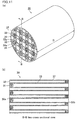
- Fig. 19(a) is a perspective view schematically illustrating a honeycomb filter disclosed in Patent Literature 3.
- Fig. 19 (b) is a perspective view schematically illustrating a honeycomb fired body forming the honeycomb filter.
- Patent Literature 3 discloses a honeycomb filter 90 that includes a plurality of honeycomb fired bodies 100 combined with one another with adhesive layers 105 residing therebetween, and an periphery coat layer 106 formed on the periphery of the combined honeycomb fired bodies, wherein the honeycomb fired bodies 100 each include exhaust gas introduction cells 102 each having an open end at an exhaust gas introduction side and a plugged end at an exhaust gas emission side, and exhaust gas emission cells 101 each having an open end at the exhaust gas emission side and a plugged end at the exhaust gas introduction side; the exhaust gas emission cells 101 each have a square cross section perpendicular to the longitudinal direction of the cells; the exhaust gas introduction cells 102 each have an octagonal cross section perpendicular to the longitudinal direction of the cells; and the exhaust gas emission cells 101 and the exhaust gas introduction cells 102 are alternately (in a grid-like pattern) arranged.
- a cell having an open end at an exhaust gas emission side and a plugged end at an exhaust gas introduction side is simply described as an exhaust gas emission cell.
- a cell having an open end at an exhaust gas introduction side and a plugged end at an exhaust gas emission side is simply described as an exhaust gas introduction cell, a first exhaust gas introduction cell, or a second exhaust gas introduction cell.
- cell means both of the exhaust gas emission cell and exhaust gas introduction cell.
- a cross section perpendicular to the longitudinal direction of cells including exhaust gas introduction cells, exhaust gas emission cells, or the like is simply described as a cross section of the exhaust gas introduction cells, exhaust gas emission cells, or the like.
- Fig. 20(a) is a perspective view schematically illustrating a honeycomb filter disclosed in Patent Literature 4.
- Fig. 20 (b) is a view schematically illustrating an end face of the honeycomb filter.
- Patent Literature 4 discloses a honeycomb filter 110 in which all cells have the same square cross-sectional shape as shown in Figs. 20(a) and 20(b) .
- exhaust gas emission cells 111 each having an open end at an exhaust gas emission side and a plugged end at an exhaust gas introduction side are fully surrounded by adjacent exhaust gas introduction cells 112 and 114 each having an open end at the exhaust gas introduction side and a plugged end at the exhaust gas emission side across cell walls 113.
- a side of the exhaust gas introduction cell 112 faces the exhaust gas emission cell 111 across the cell wall 113, whereas the corners of the exhaust gas introduction cells 114 respectively face the corners of the exhaust gas emission cells 111.
- none of the sides forming the cross sections of the exhaust gas introduction cells 114 faces the exhaust gas emission cells 111.
- the honeycomb filter disclosed in Patent Literature 1 has a compact exhaust gas clean-up system achieved by imparting a catalytic function to the honeycomb filter for capturing PMs.
- Patent Literature 1 describes that, particularly in order to impart a Selective Catalytic Reduction (SCR) function for converting NOx to a honeycomb filter, the honeycomb filter is required to support a large amount of a zeolite as a catalyst and therefore to have a high porosity and a large average pore diameter for preventing the supported catalyst from clogging the pores of the honeycomb filter.
- SCR Selective Catalytic Reduction
- the honeycomb filter of Patent Literature 1 has poor NOx conversion performance due to insufficient contact between exhaust gas and the catalyst.
- the parameter of the circularity is set to be smaller for exhaust gas introduction cells than for exhaust gas emission cells.
- the total volume of the exhaust gas introduction cells 102 is larger than the total volume of the exhaust gas emission cells 101, so that the area of the inner walls of the exhaust gas introduction cells 102 among the cell walls 103, that is, the area where PMs are to be accumulated (hereinafter, also referred to as filtration area) is increased.
- the pressure loss is less likely to be increased after accumulation of PMs and after accumulation of ashes.
- the number of the gas emission cells 101 substantially equals to the number of the exhaust gas introduction cells 102, and the exhaust gas emission cells 101 each have a smaller cross sectional area than the exhaust gas introduction cells 102. In other words, the exhaust gas emission cells 101 have a smaller average cross sectional area than the exhaust gas introduction cells 102.
- exhaust gas having flowed into the exhaust gas introduction cells 102 does not pass through the cell wall 103 easily to flow into the exhaust gas emission cell 101 until accumulation of a certain amount of PMs in the honeycomb filter 90. In such a case, in the vicinity of the end on the exhaust gas emission side of the honeycomb filter 90, the passage rate of exhaust gas passing through the cell wall 103 increases.
- exhaust gas is less likely to pass inside the cell walls 103 in the direction parallel with the inner walls of the cell walls 103.
- This structure causes insufficient contact between exhaust gas and a catalyst supported by the cell walls 103, thereby deteriorating the NOx conversion performance.
- the ratio in number between the exhaust gas emission cells 111 and the exhaust gas introduction cells 112 and 114 is substantially 1:3.
- Each exhaust gas emission cell 111 has the same cross sectional area as each exhaust gas introduction cell 112 or 114. In other words, the exhaust gas emission cells have the same average cross sectional area as the exhaust gas introduction cells.
- the passage rate of exhaust gas passing through the cell walls increases in the vicinity of the end on the exhaust gas emission side of the honeycomb filter 110 until accumulation of a certain amount of PMs in the honeycomb filter 110. This causes insufficient contact between exhaust gas and the catalyst supported by the cell walls, thereby deteriorating the NOx conversion performance.
- the present invention in consideration of the state of the art, aims to provide a honeycomb filter that can have high NOx conversion performance without supporting an excessive amount of catalyst or increasing the volume of the honeycomb filter, which has not been accomplished by the conventional art.
- the inventors of the present invention have intensively studied the above problems and they found that, in a honeycomb filter having the below features, exhaust gas having flowed into the honeycomb filter can easily come into contact with an SCR catalyst supported by cell walls regardless of the presence or absence of a certain amount of accumulated PMs; the NOx conversion performance can be improved; and the pressure loss can be totally lowered compared with conventional honeycomb filters throughout the use thereof from an initial stage to after accumulation of PMs.
- each exhaust gas emission cell is fully surrounded by exhaust gas introduction cells across porous cell walls, wherein the exhaust gas introduction cells include first exhaust gas introduction cells and second exhaust gas introduction cells each having a larger cross sectional area than each first exhaust gas introduction cell in a direction perpendicular to the longitudinal direction of the cells; and each exhaust gas emission cell has an equal or larger cross section than each second exhaust gas introduction cell.
- the exhaust gas emission cells have a larger average cross sectional area than the exhaust gas introduction cells in the direction perpendicular to the longitudinal direction of the cells; the exhaust gas introduction cells have a larger total volume than the exhaust gas emission cells; and the length of sides forming the two types of exhaust gas introduction cells, which face the exhaust gas emission cells across cell walls residing in between, or the thickness of the cell walls is controlled.
- the present invention provides a honeycomb filter including:
- the exhaust gas emission cells have a larger average cross sectional area than the exhaust gas introduction cells in a direction perpendicular to the longitudinal direction of the cells.
- exhaust gas having flowed into the exhaust gas introduction cells tends to pass through the cell walls and flow into the exhaust gas emission cells before accumulation of a certain amount of PMs.
- the exhaust gas introduction cells have a larger total volume than the exhaust gas emission cells, which increases the area of inner walls of the exhaust gas introduction cells for allowing exhaust gas to pass through. As a result, exhaust gas can pass through the cell walls without having a locally high passage rate.
- honeycomb filter can thus have high NOx conversion performance.
- the pressure loss can also be totally reduced throughout the use of the honeycomb filter from an initial stage to after accumulation of PMs.
- the SCR catalyst mentioned in the present invention refers to a catalyst that can convert NOx contained in exhaust gas into N 2 .
- Examples of the SCR catalyst include zeolites.
- Converting NOx in the presence of an SCR catalyst is usually performed by the following process. First, an aqueous solution of urea is sprayed toward a catalyst support. Then, urea contained in the aqueous solution of urea is pyrolyzed by heat of exhaust gas into ammonia. When exhaust gas containing NOx flows into cells from one end of the catalyst support, NOx contained in exhaust gas is reduced by the ammonia into N 2 while flowing along the cells.
- the SCR catalyst may be supported at any position.
- the SCR catalyst may be supported on the surface of the inner cell walls of the exhaust gas introduction cells, on the surface of the inner cell walls of the exhaust gas emission cells, inside of the cell walls, or at all the mentioned positions.
- the inventors of the present invention see that the pressure loss occurs due to (a) inflow resistance caused by exhaust gas flowing into the honeycomb filter, (b) flow-through resistance in the exhaust gas introduction cells, (c) passage resistance in the cell walls, (d) passage resistance caused by exhaust gas upon passing through a layer of accumulated PMs, (e) flow-through resistance in the exhaust gas emission cells, and (f) outflow resistance caused by exhaust gas flowing out of the honeycomb filter.
- the study of the inventors has revealed that the factors (c), (e), and (f) are controlling factors of the initial pressure loss that occurs before accumulation of PMs, and that the factors (a), (b), and (d) are controlling factors of the transitional pressure loss that occurs after accumulation of a certain amount of PMs.
- One of the controlling factors of the initial pressure loss is not the factor (b) flow-through resistance in the exhaust gas introduction cells but the factor (e) flow-through resistance in the exhaust gas emission cells because the aperture ratio of the honeycomb filter based on the exhaust gas emission cells is smaller than the aperture ratio of the honeycomb filter based on the exhaust gas introduction cells.
- the inventors consider the factor (f) outflow resistance caused by exhaust gas flowing out of the honeycomb filter, not the factor (a) inflow resistance caused by exhaust gas flowing into the honeycomb filter, as one of the controlling factors of the initial pressure loss because they suppose that the resistance due to compression of the gas is smaller than the resistance due to disturbance of emission of the exhaust gas caused by eddying flow of the gas that occurs near the emission end when the gas rapidly expands upon emission from the cells.
- the honeycomb filter of the present invention has the exhaust gas introduction cells arranged to fully surround the exhaust gas emission cells across cell walls, there are no other openings from which exhaust gas can flow out around each exhaust gas emission cell on the exhaust gas emission side. This structure is less likely to cause large eddying flow or the like upon emission of exhaust gas. This lowers the outflow resistance of the factor (f). Moreover, since the entire area of the cell walls can be used for filtration, PMs are likely to be thinly and uniformly accumulated on the inner walls of the exhaust gas introduction cells, lowering the passage resistance of the factor (d). Thus, in the provided honeycomb filter, the pressure loss is small at the initial stage and is less likely to increase even after accumulation of PMs.
- the inventors of the present invention also have found that, until accumulation of a certain amount of PMs in a conventional honeycomb filter, exhaust gas having flowed into exhaust gas introduction cells flows a long distance in the exhaust gas introduction cells to a relatively back end in the honeycomb filter, and then tends to flow into exhaust gas emission cells from local portions in the relatively back end in the honeycomb filter.
- the honeycomb filter of the present invention the (b) flow-through resistance in each exhaust gas introduction cell is made larger than the (e) flow-through resistance in each exhaust gas emission cell, and the (f) outflow resistance caused by exhaust gas flowing out of the honeycomb filter is reduced. Thereby, exhaust gas having flowed into the exhaust gas introduction cells flows into the exhaust gas emission cells through the entire cell walls in the longitudinal direction.
- Occurrence of (d) passage resistance caused by exhaust gas passing through a layer of accumulated PMs allows exhaust gas to pass, in addition to a direction from the exhaust gas introduction cells toward the exhaust gas emission cells, inside the cell walls in a direction parallel with the inner walls of the exhaust gas introduction cells.
- exhaust gas can be efficiently brought into contact with the catalyst supported by the cell walls, which can improve the NOx conversion performance.
- the honeycomb filter of the present invention supports a zeolite as an SCR catalyst.
- the zeolite encompasses, in addition to aluminosilicates, zeolite analogs such as aluminophosphates and aluminogermanates.
- Examples of the zeolite to be supported by the cell walls of honeycomb fired bodies constituting the honeycomb filter include CHA-type zeolites, ⁇ -type zeolites, Y-type zeolites, ferrierites, ZSM-5 type zeolites, mordenites, faujasites, A-type zeolites, L-type zeolites, silicoaluminophosphates (SAPOs), and metalaluminophosphates (MeAPOs).
- CHA-type zeolites and SAPOs are preferred among the mentioned zeolites.
- SSZ-13 is preferred as a CHA-type zeolite, and SAPO-34 is preferred as a SAPO.
- the honeycomb filter of the present invention supports preferably 80 to 150 g of the SCR catalyst per liter of an apparent volume of the honeycomb filter.
- the amount of the SCR catalyst supported is 80 to 150 g/L, a required NOx conversion rate can be achieved and an increase in the pressure loss of the honeycomb filter due to supporting a catalyst can be minimized.
- the amount of the SCR catalyst supported is less than 80 g/L, the amount is too small and thus the NOx conversion rate is reduced. If the amount of the SCR catalyst supported is more than 150 g/L, the amount is too large and thus the volume of pores is reduced and the pressure loss is increased.
- An amount of 80 to 150 g/L of the SCR catalyst supported means that 80 to 150 g of the SCR catalyst is supported per liter of an apparent volume of the honeycomb filter.
- the SCR catalyst supported by the honeycomb filter of the present invention is preferably a Cu ion-exchanged zeolite.
- a Cu ion-exchanged zeolite has high adsorption performance for ammonium to be used in the SCR system and thereby can improve the NOx conversion performance.
- a Cu ion-exchanged zeolite has high hydrothermal durability and thus can keep good NOx conversion performance even after a long-term use.
- the honeycomb filter of the present invention supports preferably 1 to 10 g/L of Cu.
- An amount of 1 to 10 g/L of Cu supported, similarly to the aforementioned case, means that 1 to 10 g of Cu is supported per liter of an apparent volume of the honeycomb filter.
- honeycomb filter of the present invention supports the SCR catalyst preferably on the surfaces and inside of the cell walls to cause the following effects.
- cross sectional shape of a cell refers to a shape formed by an inner cell wall of the exhaust gas emission cell, first exhaust gas introduction cell, or second exhaust gas introduction cell in the direction perpendicular to the longitudinal direction of the cell.
- cross sectional area of a cell herein refers to an area of a cross sectional shape formed by an inner cell wall of each exhaust gas emission cell, first exhaust gas introduction cell, or second exhaust gas introduction cell in a cross section perpendicular to the longitudinal direction of the cell.
- inner cell wall refers to a surface on the inner side of a cell among surfaces of cell walls defining rims of cells.
- side refers to a segment between vertices of a polygon in the case where cross sectional shapes formed by inner cell walls of the exhaust gas emission cells, the first exhaust gas introduction cells, or the second exhaust gas introduction cells are polygons in a direction perpendicular to the longitudinal direction of the cells.
- volume of a cell refers to a volume of a part surrounded by inner walls except for the plugged portion of the cell.
- total volume refers to the total sum of the volumes. The volume of the cell is calculated by multiplying the cross sectional area of the cell and the length of the cell excluding the length of the plugged portion.
- the term "length of a side” means the length of the segment.
- the length of a side means the length of a straight line excluding the curved line portions for the following reasons.
- the vertex portions are formed by curved lines
- the cell walls separating the cells are thick in the curve portions, and thus the curve portions have high passage resistance. This causes exhaust gas to preferentially flow into straight line portions, and thus the length of the straight portions needs to be controlled. Hence, it is reasonable to exclude the curve portions from consideration.
- the length of the straight portion of the side excluding the curve portion is preferably not less than 80% the length of a hypothetical side given by connecting the hypothetical vertices.
- a main-channel-switching effect which is a functional effect of the present invention, can be achieved by adjusting the length of the sides.
- a side forming the cross sectional shape of a first exhaust gas introduction cell or a second exhaust gas introduction cell is considered to face an exhaust gas emission cell when the following condition is satisfied.
- a hypothetical perpendicular line hereinafter referred to as a perpendicular bisector
- the perpendicular bisector crosses a shape region defined by the inner cell wall of an exhaust gas emission cell which is adjacent to the first exhaust gas introduction cell or a second exhaust gas introduction cell across a cell wall.
- a first exhaust gas introduction cell or second exhaust gas introduction cell having a side facing an exhaust gas emission cell is considered to face the exhaust gas emission cell.
- a side forming the cross sectional shape of an exhaust gas emission cell is considered to face a first exhaust gas introduction cell or a second exhaust gas introduction cell when the following condition is satisfied.
- a hypothetical perpendicular line hereinafter referred to as a perpendicular bisector
- the perpendicular bisector crosses a shape region defined by the inner cell wall of a first exhaust gas introduction cell or a second exhaust gas introduction cell which is adjacent to the exhaust gas emission cell across a cell wall.
- an exhaust gas emission cell having a side facing a first exhaust gas introduction cell or a second exhaust gas introduction cell is considered to face the first exhaust gas introduction cell or the second exhaust gas introduction cell.
- a side forming a first exhaust gas introduction cell is considered to face a second exhaust gas introduction cell when the following condition is satisfied.
- a hypothetical perpendicular line hereinafter referred to as a perpendicular bisector
- the perpendicular bisector crosses a shape region defined by the inner cell wall of a second exhaust gas introduction cell which is adjacent to the first exhaust gas introduction cell across a cell wall.
- a first exhaust gas introduction cell having a side facing a second exhaust gas introduction cell is considered to face the second exhaust gas introduction cell.
- a side forming a second exhaust gas introduction cell is considered to face a first exhaust gas introduction cell when the following condition is satisfied.
- a hypothetical perpendicular line hereinafter referred to as a perpendicular bisector
- the perpendicular bisector crosses a shape region defined by the inner cell wall of a first exhaust gas introduction cell which is adjacent to the second exhaust gas introduction cell across a cell wall.
- the second exhaust gas introduction cell having a side facing a first exhaust gas introduction cell is considered to face the first exhaust gas introduction cell.
- the thickness of a cell wall separating two cells is defined as follows.
- the centers of gravity herein refer to geometric centers of gravity of cross sectional figures defined by inner cell walls.
- the center of gravity can be defined even for cross sectional figures of void such as cells.
- the word “adjacent” herein is equivalent to the word “adjacent” in Japanese.
- the word “adjacent” is used not only for a case where exhaust gas introduction cells are arranged to face exhaust gas emission cells across porous cell walls, but also for a case where exhaust gas introduction cells are not facing but arranged diagonally to exhaust gas emission cells across porous cell walls.
- the expression “Lattices are diagonally adjacent to each other” is accepted as an exemplary expression using "adjacent”.
- exhaust gas introduction cells and exhaust gas emission cells each have a polygonal cross sectional shape and are arranged to face each other across porous cell walls is specifically illustrated in Figs. 2 and 3 .
- a second exhaust gas introduction cells 14 face exhaust gas emission cells 11 across porous cell walls 13.
- exhaust gas introduction cells and exhaust gas emission cells each have a round or elliptical cross sectional shape and a single porous cell wall is formed by curves of the cross sectional shapes of an exhaust gas introduction cell and an exhaust gas emission cell
- the exhaust gas introduction cell and the exhaust gas emission cell are considered to be arranged to face each other across a porous cell wall according to the case where exhaust gas introduction cells and exhaust gas emission cells each have a polygonal cross sectional shape.
- exhaust gas introduction cells 54 are considered to face exhaust gas emission cells 51 across porous cell walls 53.
- exhaust gas introduction cells and exhaust gas emission cells each have a polygonal cross sectional shape and are not arranged to face each other but arranged diagonally across porous cell walls is specifically illustrated in Fig. 14 .
- second exhaust gas introduction cells 44 and exhaust gas emission cells 41 do not face each other and are arranged diagonally across porous cell walls 43.
- exhaust gas introduction cells and exhaust gas emission cells each have a shape formed by curved lines, except for round or elliptical shape
- an intersection of two curved lines is considered to be a vertex and a curved line between two vertices is considered to be a side.
- a side (curved line) of an exhaust gas emission cell or exhaust gas introduction cell is considered to face an exhaust gas introduction cell or exhaust gas emission cell when the following condition is satisfied.
- a hypothetical perpendicular line which bisects a segment between vertices at the both ends of a side (curved line) forming the cross sectional shape of an exhaust gas emission cell or an exhaust gas introduction cell (A) is given from the side toward the outside the exhaust gas emission cell or the exhaust gas introduction cell (A), the perpendicular bisector crosses a shape region defined by the inner cell wall of an exhaust gas introduction cell or an exhaust gas emission cell (B) that is closest to the cell (A) across a cell wall.
- the exhaust gas emission cell or the exhaust gas introduction cell (A) is described to face the exhaust gas introduction cell or the exhaust gas emission cell (B).
- the vertex portions formed by curved lines so-called chamfered shape
- the curved lines are extended, and the hypothetical intersection of the extended lines is considered to be a vertex.
- a case where exhaust gas introduction cells and exhaust gas emission cells each have a shape formed by curved lines, except for round or elliptical shape a case where exhaust gas introduction cells and exhaust gas emission cells do not face each other and are arranged diagonally across porous cell walls is specifically illustrated in Fig. 17 .
- second exhaust gas introduction cells 64 and exhaust gas emission cells 61 do not face each other and arranged diagonally across porous cell walls 63.
- the phrase "arranged diagonally” refers to the arrangement in which exhaust gas introduction cells and exhaust gas emission cells do not face each other and satisfy the following condition.
- a hypothetical segment between the geometrical center of gravity and a vertex in the case of chamfered vertex portions, sides (straight or curved lines) forming the cross sectional figure are hypothetically extended and an intersection of the extended lines is considered to be a vertex) of a cross sectional figure formed by the inner cell wall of the exhaust gas emission cell is provided.
- a hypothetical segment between the geometrical center of gravity and a vertex (in the case of chamfered vertex portions, sides (straight or curved lines) forming the cross sectional figure are hypothetically extended and an intersection of the extended lines is considered to be a vertex) of a cross sectional figure formed by the inner cell wall of the exhaust gas introduction cell is provided.
- the provided hypothetical segments are parallel with each other or overlapped with each other. It is to be noted that, if a pair of hypothetical lines among plural hypothetical lines is parallel or overlapped with each other, the other hypothetical lines may be across with each other at a predetermined angle (e.g., 90°).
- exhaust gas introduction cell refers to both the first exhaust gas introduction cell and the second exhaust gas introduction cell.
- Fig. 3(b) is an enlarged end face view illustrating an enlarged image of a part of an end face of the honeycomb filter according to one embodiment of the present invention.
- Fig. 3 illustrates exhaust gas emission cells 11, and first exhaust gas introduction cells 12 and second exhaust gas introduction cells 14 surrounding the exhaust gas emission cells 11.
- a side forming the cross sectional shape of a first exhaust gas introduction cell 12 or a second exhaust gas introduction cell 14 is considered to face an exhaust gas emission cell 11 when the following condition is satisfied. Provided that, in the cross section perpendicular to the longitudinal direction of the cells shown in Fig.
- a hypothetical perpendicular line (hereinafter referred to as a perpendicular bisector) which bisects a side 12a of a polygon formed by the inner cell wall of a first exhaust gas introduction cell 12 or a side 14a of a polygon formed by the inner cell wall of a second exhaust gas introduction cell 14 is given from the side to outside the first exhaust gas introduction cell 12 or the second exhaust gas introduction cell 14, the perpendicular bisector A or the perpendicular bisector B crosses a shape region (side 11a, side 11b) defined by the inner cell wall of an exhaust gas emission cell 11 which is adjacent to the side 12a of the first exhaust gas introduction cell 12 or the side 14a of the second exhaust gas introduction cell 14 across a cell wall as shown in Fig. 3 .
- the reason why the crossing of the bisector is set as a condition for the facing in the present invention is that the passage resistance caused upon allowing exhaust gas to pass through at or around the center of the side in the length direction, i.e. at or around the center of the cell wall separating the exhaust gas introduction cell and the exhaust gas emission cell, represents a pressure loss caused upon allowing exhaust gas to pass through the entire wall.
- the cross sectional shape defined by the inner cell wall of each exhaust gas emission cell, first exhaust gas introduction cell, or second exhaust gas introduction cell is a polygon, and the vertex portions of the polygon are chamfered, i.e. formed by curved lines in the cross section perpendicular to the longitudinal direction of the cells, the bisectors of respective sides are bisectors of segments excluding the curved lines.
- the curved lines are not included in the sides.
- the sides forming the cross sectional shape are hypothetically extended, and intersections of the extended sides are considered as hypothetical vertices.
- the cross sectional shape is treated as a polygon.
- the vertex portions of the polygonal cross sectional shapes may be formed by curved lines to prevent concentration of stress at the vertex portions.
- Such cross sections in which the vertex portions are formed by curved lines are considered as polygons.
- the thickness of a cell wall separating two cells is defined as follows.
- the center of gravity of the exhaust gas emission cell 11 is O 11
- the center of gravity of the second exhaust gas introduction cells is O 14 in Fig. 3
- the length D of the segment of the line Z 14 overlapping the cell wall area is defined as the thickness of the cell wall.
- the thickness of the cell wall is defined as above for the following reasons.
- the passage resistance caused upon allowing gas to pass through the cell walls is the highest at a portion of the cell wall where the gas passes through at the highest flow rate, and the passage resistance at the portion may represent the passage resistance of the cell wall.
- the flow rate of gas in the longitudinal direction of the honeycomb filter is the highest at positions corresponding to the geometric centers of gravity of the cross sectional shapes defined by the inner cell walls.
- the flow rate concentrically decreases from the center of gravity toward the circumference of the cross sectional shape of the cells.
- the flow rate of gas passing through a cell wall is the highest at an intersection of the cell wall and a line connecting the center of gravity of an exhaust gas introduction cell and the center of gravity of an exhaust gas emission cell.
- electron microscope pictures are used for measurement of the length of sides and the thickness of cell walls, and identification of the cross sectional shapes of cells.
- the electron microscope pictures are taken with an electron microscope (FE-SEM: High resolution field emission scanning electron microscope S-4800, manufactured by Hitachi High-Technologies Corporation).
- the electron microscope pictures are preferably those taken by the electron microscope at a magnification of 30X. This is because, at a magnification of 30X, irregularities due to particles or pores on the surface (inner wall) of cell walls defining the rims of cells do not disturb identification of the cross sectional shapes of the cells, measurement of the lengths of sides, thicknesses of cell walls, and cross sectional area of the cells. Also, at a magnification of 30X, the cross sectional shapes of the cells can be identified, and the lengths of sides, thicknesses of cell walls, and cross sectional area of the cells can be measured.
- the lengths of the respective sides of the cell are measured using the scale of the electron microscope photographs based on the above definitions of the length of the cells and the thickness of the cell walls.
- the cross sectional area is arithmetically determined based on the obtained values including the length of the cells.
- the cross sectional area can also be determined by cutting a square piece (a square with a side having a scale length) corresponding to a unit area out of the electron microscope photograph, and weighing the cut-out piece, while separately cutting the cross section of the cell out along the cross sectional shape of the cell (along curved lines in the case of a polygonal cross section with the vertex portions formed by curved lines), and weighing the cut-out piece, and then calculating the cross sectional area of the cell based on the weight ratio.
- the cross sectional shapes defined by the inner walls of the exhaust gas emission cells and the second exhaust gas introduction cells are octagons having the same cross sectional area from one another, and the cross sectional shapes defined by the respective inner walls of the first exhaust gas introduction cells are square (although the vertex portions have so-called roundly-cornered shape (i.e. formed by curved lines), the cross sectional shapes are each considered as a square having four sides and four vertices at four intersections of straight lines extended from the four sides forming the cross sectional shape in the present invention).
- a 500 ⁇ m scale is displayed.
- a square (corresponding to a unit area) having each side in a length corresponding to 500 ⁇ m in the photograph is cut out of the photograph, and the cut-out piece is weighed.
- the octagon and the square are cut out of the photograph (the four vertex portions formed by curved lines in the square are cut along the curved lines), and the cut-out pieces are weighed.
- the cross sectional area is calculated based on the weight ratio between the cut-out piece and the 500 ⁇ m scale square. In the case of measuring only the cross sectional area ratio of the cells, the area ratio can be obtained directly from the weight ratio between the octagon and the square.
- the measurement of the lengths of the cells, the thicknesses of the cell walls, and the cross sectional areas can be changed from the above manual measurement to an electronic measurement by scanning the electron microscope photograph as image data, or using the image data directly output from the electron microscope and entering the scale of the photograph.
- the manual measurement and the electronic measurement are both based on the scale of the electron microscope image, and are in accordance with the same principle. Thus, surely no discrepancies are found between the measurement results of the respective measurements.
- the electronic measurement may be performed by using an image analysis and grain size distribution measurement software (Mac-View (Version 3.5), produced by Mountech Co. Ltd.).
- Mac-View Very Text Generation
- This software measures a cross sectional area by scanning an electron microscope photograph as image data, or using the image data directly output from the electron microscope, entering the scale of the photograph, and specifying the area along the inner wall of the cell.
- the distance between any two points in the image can be measured based on the scale of the electron microscope photograph.
- a photograph of the cross section of the cells is taken with the electron microscope by cutting a filter in a direction perpendicular to the longitudinal direction of the cells to prepare a 1 cm x 1 cm x 1 cm sample including the cut face and ultrasonic cleaning the cut section of the sample, or coating a filter with resin and cutting the coated filter in a direction perpendicular to the longitudinal direction of the cells, and then taking an electron microscope photograph of the sample.
- the resin coating does not affect measurement of the lengths of the sides of the cells and the thicknesses of the cell walls.
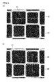
- Figs. 4(a) and 4(b) are each a photograph showing one example of the shape of the cross section of cells taken with a scanning electron microscope.
- Figs. 4 (a) reveals that the cross sectional shapes of the exhaust gas emission cells 11 and the second exhaust gas introduction cells 14 are each octagonal.
- the cross sectional shape of the first exhaust gas introduction cells 12 is square.
- the vertex portions of each first exhaust gas introduction cell are formed by slightly curved lines; however, extension of the four sides, which are straight lines, of the first exhaust gas introduction cell 12 intersect at four intersections to form a square having the intersections as vertices.
- the cross section of the cell is considered square according to the definition of the present invention.
- the length of a side Ls facing the exhaust gas emission cell 11 among the sides forming the cross sectional shape of the first exhaust gas introduction cell 12 is the length excluding the curved portions.
- the length Lo of a side facing the exhaust gas emission cell among the sides forming the cross sectional shape of the second exhaust gas introduction cell 14 corresponds to the distance between the vertices of the octagon.
- the lengths of the sides Ls and Lo, and the cross sectional area can be measured using the scanning electron microscope photograph.
- Figs. 5(a) and 5(b) are each a scanning electron microscope photograph (SEM photograph) showing one example of the cross sectional shapes of cells that are different from the cells shown in Fig. 4 .
- Fig 5(a) shows that the cross sectional areas of the respective exhaust gas emission cell 41, the second exhaust gas introduction cell 44, and the first exhaust gas introduction cells 42 are each in a shape in which straight lines hypothetically extended from the four sides having equal length perpendicularly intersect one another at intersections (vertices), and the vertex portions are formed by curved lines.
- the vertex portions of the cross sectional shape of the cell are formed by curved lines, lines extended from the four straight lines forming each cell intersect at four intersections. Supposing that the intersections are hypothetical vertices, the four distances between the vertices are the same from one another to form a square.
- the cross sectional shapes of the respective cells are considered square according to the definition of the present invention.
- a perpendicular bisector of a side forming the first exhaust gas introduction cell 42 crosses the exhaust gas emission cell 41.
- the side forming the first exhaust gas introduction cell 42 faces the exhaust gas emission cell 41.
- a perpendicular bisector of a side forming the second exhaust gas introduction cell 44 does not intersect with the exhaust gas emission cell 41.
- the side forming the second exhaust gas introduction cell 44 does not face the exhaust gas emission cell 41.
- whether a side forming the second exhaust gas introduction cell 44 or the first exhaust gas introduction cell 42 faces the exhaust gas emission cell 41 can be determined from the electron microscope photograph.
- a convex square according to the present invention is a shape formed by four outwardly curved lines of the same length. The square looks as if its sides bulge from the geometric center of gravity to the outside.
- a concave square is a shape formed by four inwardly curved lines of the same length. The square looks as if its sides concave toward the geometric center of gravity.
- the first exhaust gas introduction cells, the second exhaust gas introduction cells, and the exhaust gas emission cells each have a uniform cross sectional shape thoroughly from the exhaust gas introduction end to the exhaust gas emission end except for the plugged portion.
- the cross sectional shape defined by the inner wall thereof has the same shape at any part from the exhaust gas introduction end to the exhaust gas emission end except for the plugged portion.
- the same shape means a congruent shape, and excludes similar shapes.
- a similar shape means a different shape.
- the explanation for the first exhaust gas introduction cell also applies to the second exhaust gas introduction cell and the exhaust gas emission cell.
- the plugged portions are excluded because the cross sectional shape defined by the inner cell wall does not physically exist at the plugged portions due to the presence of the plugs.
- honeycomb filter of the present invention can comprehensively reduce the pressure loss thoroughly from the initial stage to the stage after accumulation of PMs in close to the limit amount, as compared to conventional honeycomb filters.
- the flow-through resistance and the outflow resistance need to be reduced for reducing the initial pressure loss.
- the cross sectional area of the exhaust gas emission cells needs to be equal to or relatively larger than the cross sectional area of the exhaust gas introduction cells for suppressing the rapid expansion. Wide and thin accumulation of PMs is necessary for reducing the transitional pressure loss.
- the cross sectional area of the exhaust gas introduction cells needs to be relatively larger than the cross sectional area of the exhaust gas emission cells.
- exhaust gas is preferentially introduced firstly into the first exhaust gas introduction cells when the honeycomb filter has the following structures: two kinds of the exhaust gas introduction cells including the exhaust gas introduction cells each having a larger cross sectional area (second exhaust gas introduction cells) and the exhaust gas introduction cells each having a smaller cross sectional area (first exhaust gas introduction cells) are employed as the exhaust gas introduction cells; each exhaust gas emission cell has an equal or larger cross sectional area than each second exhaust gas introduction cell; each exhaust gas emission cell is fully surrounded by the two kinds of the exhaust gas introduction cells; and the length of the inner wall separating the first exhaust gas introduction cell and the exhaust gas emission cell is relatively longer than the length of the inner wall separating the second exhaust gas introduction cell and the exhaust gas emission cell, or the thickness of the wall separating the first exhaust gas introduction cell and the exhaust gas emission cell is relatively smaller than the thickness of the wall separating the second exhaust gas introduction cell and the exhaust gas emission cell.
- the wall separating the first exhaust gas introduction cell and the exhaust gas emission cell has a larger passage area (in the case of polygonal cells, sides are long in the cross sectional shape) or the thickness of the wall is smaller. Exhaust gas can thus pass through such an advantageous wall so that the passage resistance of the factor (c) can be reduced. Also, the flow-through resistance of the factor (e) can be reduced as the cross sectional area of the exhaust gas emission cells is relatively larger than the cross sectional area of the first exhaust gas introduction cells. Namely, both of the passage resistance of the factor (c) and the flow-through resistance of the factor (e) can be reduced, and thereby the initial pressure loss can be reduced.
- the present invention has achieved a surprising effect, which has been considered impossible, of reducing both of the transitional pressure loss and the initial pressure loss by the autonomous switching of the main flow channel.
- Patent Literature 3 discloses a honeycomb filter including exhaust gas introduction cells 102 each having an octagonal cross sectional shape and exhaust gas emission cells 101 each having a rectangular cross sectional shape as shown in Fig. 19 .
- Patent Literature 3 discloses that an increase in the cross sectional area of the exhaust gas introduction cells 102 enables wide and thin accumulation of PMs, and thus the transitional pressure loss can be reduced.
- some of the exhaust gas emission cells 101 each having a smaller cross sectional area need to be changed to the exhaust gas introduction cells 102, and some of the exhaust gas introduction cells 102 each having a larger cross sectional area need to be changed to the exhaust gas emission cells 101.
- Such changes deny the inventive concept of the invention of Patent Literature 3, i.e. increasing the cross sectional area of the exhaust gas introduction cells 102.
- the present invention cannot be achieved in view of Patent Literature 3 as the closest prior art document.
- Patent Literature 4 discloses a honeycomb filter which can reduce the transitional pressure loss by increasing the number of exhaust gas introduction cells having the same cross sectional area to increase the total area of the exhaust gas introduction cells so that PMs are allowed to widely and thinly accumulate.
- Figs. 6(a) to 6(c) are each an enlarged end face view illustrating an enlarged image of a part of an end face of the honeycomb filter according to one embodiment of the present invention.
- each exhaust gas emission cell 11 having an open end at an exhaust gas emission side and a plugged end at an exhaust gas introduction side is adjacently surrounded fully by first exhaust gas introduction cells 12 and second exhaust gas introduction cells 14 each having an open end at the exhaust gas introduction side and a plugged end at the exhaust gas emission side across porous cell walls 13.
- the exhaust gas emission cell 11 has an octagonal cross section that is the same as or similar to that of the exhaust gas introduction cell 102 shown in Fig. 19
- the first exhaust gas introduction cell 12 has a square cross section
- the second exhaust gas introduction cell 14 has an octagonal square section that is the same as that of the exhaust gas emission cell 11.
- the second exhaust gas introduction cell 14 has a larger cross sectional area than the first exhaust gas introduction cell 12, and the cross sectional area is the same as the exhaust gas emission cell 11. That is, the second exhaust gas introduction cell 14 has the same cross sectional area as the exhaust gas emission cell 11, and the exhaust gas emission cell 11 has a larger cross sectional area than the first exhaust gas introduction cell 12.
- a side 12a facing the exhaust gas emission cell 11 among the sides forming the cross sectional shape of the first exhaust gas introduction cell 12 is longer than a side 14a facing the exhaust gas emission cell 11 among the sides forming the cross sectional shape of the second exhaust gas introduction cell 14.
- Exhaust gas flowing toward the honeycomb filter 20 flows into the first exhaust gas introduction cells 12 each having an open end at the exhaust gas introduction side and the second exhaust gas introduction cells 14 each having an open end at the exhaust gas introduction side.
- the exhaust gas flows in the filter in order from a part allowing easier flow and then evenly flows in the entire filter.
- the length (Ls) of the side 12a of the first exhaust gas introduction cell 12 is larger than the length (Lo) of the side 14a of the second exhaust gas introduction cell 14.
- the surface area of a cell wall 13a separating the exhaust gas emission cell 11 and the first exhaust gas introduction cell 12 is larger than the surface area of a cell wall 13b separating the exhaust gas emission cell 11 and the second exhaust gas introduction cell 14, leading to easier exhaust gas passage through the cell wall 13a. Consequently, PMs accumulate on the cell walls 13a at an initial stage.
- both of the flow-through resistance of the exhaust gas emission cells and the outflow resistance upon emission of exhaust gas from the honeycomb filter can be reduced.
- the initial pressure loss before accumulation of PMs can be reduced.
- the surface area of the cell wall 13a separating the exhaust gas emission cell 11 and the first exhaust gas introduction cell 12 corresponds to the surface area of the inner wall of the first exhaust gas introduction cell 12.
- the surface area of the inner wall of the first exhaust gas introduction cell 12 is expressed as Ls x Le, where Le represents an effective length of the filter excluding the length of the plugged portions at the introduction side from the exhaust gas introduction end and at the emission side from the exhaust gas emission end (see Fig. 2(b) ).
- Le represents an effective length of the filter excluding the length of the plugged portions at the introduction side from the exhaust gas introduction end and at the emission side from the exhaust gas emission end (see Fig. 2(b) ).
- the surface area of the cell wall 13b separating the exhaust gas emission cell 11 and the second exhaust gas introduction cell 14 corresponds to the surface area of the inner wall of the second exhaust gas introduction cell 14.
- the surface area of the inner wall of the second exhaust gas introduction cell 14 is expressed as Lo x Le, where Le represents an effective length of the filter excluding the length of the plugged portions at the introduction side from the exhaust gas introduction end and at the emission side from the exhaust gas emission end.
- the effective length of the filter is defined as a length measured from the tip of a plug in Fig. 2(b) .
- the length (Ls) of the side 12a is larger than the length (Lo) of the side 14a
- the surface area value of Ls x Le is relatively larger than the surface area value of Lo x Le.
- the length of the side is equivalent to the surface area.
- exhaust gas can considerably freely pass through the cell walls, exhaust gas passes through inside the cell walls 13c separating the first exhaust gas introduction cells 12 and the second exhaust gas introduction cells 14 to flow into the exhaust gas emission cells 11 as shown in Fig. 6(c) . In this situation, exhaust gas enters the cell walls 13c from the first exhaust gas introduction cells 12 as well as from the second exhaust gas introduction cells 14.
- PMs accumulate on the entire surfaces of the cell walls 13a and 13c around the first exhaust gas introduction cells 12 corresponding the inner walls of the first exhaust gas introduction cells 12, and gradually accumulate rather more widely and thinly in a larger amount on the entire surfaces of the cell walls 13b and 13c around the second exhaust gas introduction cells 14 corresponding to the inner walls of the second exhaust gas introduction cells 14.
- the first exhaust gas introduction cells 12 each have a smaller cross sectional area than each second exhaust gas introduction cell 14.
- the introduced exhaust gas flows more easily into the second exhaust gas introduction cells 14 than into the first exhaust gas introduction cells 12 at an early stage (aforementioned switching of the main channel of exhaust gas), causing the aforementioned shift of the PM accumulation. Consequently, PMs accumulate more on the entire surfaces of the cell walls 13b and 13c around the second exhaust gas introduction cells 14 corresponding to the inner walls of the second exhaust gas introduction cells 14 rather than the surfaces of the cell walls 13a and 13c around the first exhaust gas introduction cells 12 corresponding to the inner walls of the first exhaust gas introduction cells 12. It is thus possible to make use of the entire surfaces of the cell walls 13b and 13c around the second exhaust gas introduction cells 14 corresponding to the inner walls of the second exhaust gas introduction cells 14 for accumulation of PMs earlier.
- the surface area of the cell walls 13b and 13c around the second exhaust gas introduction cells 14 corresponding to the inner walls of the second exhaust gas introduction cells 14 is larger than the surface area of the cell walls 13a and 13c around the first exhaust gas introduction cells 12 corresponding to the inner walls of the first exhaust gas introduction cells 12, when PMs accumulate on the entire peripheries of the cell walls 13b and 13c surrounding the second exhaust gas introduction cells 14, the accumulated layer is thin.
- the pressure loss due to exhaust gas increases at a low rate even after accumulation of PMs.
- a surprisingly excellent effect of maintaining the pressure loss at a low level can be achieved even though the amount of accumulated PMs increases.
- vehicles carrying the honeycomb filter according to the present invention do not cause a disadvantageous phenomenon for driving that are derived from an increase in the pressure loss throughout the use area, and also have good fuel economy.
- the honeycomb filter of the present invention preferably has the following structure.
- a side, among the sides forming the cross sectional shape of the exhaust gas emission cell, which is adjacent to the first exhaust gas introduction cell across the cell wall in a manner facing the first exhaust gas introduction cell is parallel to a side, among the sides forming the cross sectional shape of the first exhaust gas introduction cell, which is adjacent to the exhaust gas emission cell across the cell wall in a manner facing the exhaust gas emission cell.
- the thickness is uniform at any part of the walls separating the exhaust gas emission cells and the first exhaust gas introduction cells.
- the curve portions are not considered as sides because naturally such portions do not form parallel lines.
- the length of each side of the cross sectional shape excluding the curve portion is preferably not less than 80% the length of a hypothetical side of a polygon that is formed by connecting the hypothetical vertices.
- the length of the portion not considered as a side is preferably less than 20% the length of the hypothetical side.
- the main-channel-switching effect which is an effect of the present invention, can be achieved by controlling the length of the sides.
- the honeycomb filter of the present invention preferably has the following structure.
- a side, among the sides forming the cross sectional shape of the exhaust gas emission cell, which is adjacent to the second exhaust gas introduction cell across the cell wall in a manner facing the second exhaust gas introduction cell is parallel to a side, among the sides forming the cross sectional shape of the second exhaust gas introduction cell, which is adjacent to the exhaust gas emission cell across the cell wall in a manner facing the exhaust gas emission cell.
- the curve portions are not considered as sides because naturally such portions do not form parallel lines.
- the length of each side of the cross sectional shape excluding the curve portion is preferably not less than 80% the length of a hypothetical side of a polygon that is formed by connecting the hypothetical vertices.
- the length of the portion not considered as a side is preferably less than 20% the length of the hypothetical side.
- the main-channel-switching effect which is an effect of the present invention, can be achieved by controlling the length of the sides.
- the honeycomb filter of the present invention preferably has the following structure.
- a side, among the sides forming the cross sectional shape of the first exhaust gas introduction cell, which is adjacent to the second exhaust gas introduction cell across the cell wall in a manner facing the second exhaust gas introduction cell is parallel to a side, among the sides forming the cross sectional shape of the second exhaust gas introduction cell, which is adjacent to the first exhaust gas introduction cell across the cell wall in a manner facing the first exhaust gas introduction cell.
- the thickness is uniform at any part of the walls separating the first exhaust gas introduction cells and the second exhaust gas introduction cells.
- the vertex portions of the polygonal cross section are formed by curved lines
- the curve portions are not considered as sides because naturally such portions do not form parallel lines.
- the length of each side of the cross sectional shape excluding the curve portion is preferably not less than 80% the length of a hypothetical side of a polygon that is formed by connecting the hypothetical vertices.
- the length of the portion not considered as a side is preferably less than 20% the length of the hypothetical side.
- the main-channel-switching effect which is an effect of the present invention, can be achieved by controlling the length of the sides.
- the honeycomb filter according to the present invention preferably has the following structure.
- the exhaust gas emission cell, the first exhaust gas introduction cell, and the second exhaust gas introduction cell which are adjacent to one another across cell walls, each have a polygonal cross sectional shape in the cross section perpendicular to the longitudinal direction of the cells,
- the distance between the parallel sides in the above condition (a), the distance between the parallel sides in the above condition (b), and the distance between the parallel sides in the above condition (c) are preferably the same in the structure simultaneously satisfying the conditions (a), (b), and (c).
- the distance between the sides is defined as follows: a hypothetical perpendicular line is given from an arbitrary point P in one side to a point Q in the other side, and the distance between the point P and the point Q is defined as the distance between the parallel sides.
- the honeycomb filter having the above structure has the highest fracture strength, has excellent thermal shock resistance upon regeneration, can best reduce the pressure loss regardless of the presence or absence of accumulated PMs, and can avoid thermal shock damage that occurs upon regeneration of PMs.
- the vertex portions of the polygonal cross section are formed by curved lines
- the curve portions are not considered as sides because naturally such portions do not form parallel lines.
- the length of each side of the cross sectional shape excluding the curve portion is preferably not less than 80% the length of a hypothetical side of a polygon that is formed by connecting the hypothetical vertices.
- the length of the portion not considered as a side is preferably less than 20% the length of the hypothetical side.
- the main-channel-switching effect which is an effect of the present invention, can be achieved by controlling the length of the sides.
- the honeycomb filter of the present invention is preferably used to purify PMs in exhaust gas discharged from internal combustion engines of automobiles.
- the honeycomb filter can reduce both of the initial pressure loss before accumulation of PMs and the transitional pressure loss caused by accumulation of PMs in the filter, and thereby the fuel economy of the engine can be enhanced.
- the honeycomb filter of the present invention is most suitably used in automobiles whose internal combustion engines are diesel engines.
- the amount of PMs discharged from a diesel engine is larger than that from a gasoline engine.
- a demand for reducing the transitional pressure loss caused by accumulation of PMs in the filter is higher for diesel engines than for gasoline engines.
- the honeycomb filter of the present invention is fixed inside an exhaust tube via a holding material.
- each exhaust gas emission cell and each exhaust gas introduction cell in the cross section perpendicular to the longitudinal direction of the cells, each exhaust gas emission cell and each exhaust gas introduction cell preferably have a polygonal cross section, and a side forming the cross sectional shape of each first exhaust gas introduction cell faces one of the exhaust gas emission cells, a side forming the cross sectional shape of each second exhaust gas introduction cell faces one of the exhaust gas emission cells, and the length of the side forming the cross sectional shape of the second exhaust gas introduction cell is not more than 0.8 times the length of the side forming the cross sectional shape of the first exhaust gas introduction cell.
- the honeycomb filter having the above structure enables easier passage of exhaust gas through the cell walls separating the exhaust gas emission cells and the first exhaust gas introduction cells, effective suppression of the initial pressure loss, and prevention of an increase in the rate of increase of the pressure loss after accumulation of PMs.
- the exhaust gas emission cells are each octagonal
- the first exhaust gas introduction cells are each square
- the second exhaust gas introduction cells are each octagonal.
- the honeycomb filter having the above structure has the same shape as the honeycomb filter in Fig. 6 that is described concerning the effects thereof.
- the honeycomb filter can effectively suppress the initial pressure loss, have a large surface area for allowing PMs to accumulate thereon, and can maintain the pressure loss at a low level.
- the cross sectional area of each second exhaust gas introduction cell is equal in size to the cross sectional area of each exhaust gas emission cell, and the cross sectional area of each first exhaust gas introduction cell is 20 to 50% the size of the cross sectional area of each second exhaust gas introduction cell.
- the honeycomb structure having the above structure can provide difference between the resistance caused upon flowing of exhaust gas through the first exhaust gas introduction cells and the resistance caused upon flowing of exhaust gas through the second exhaust gas introduction cells, thereby enabling effective suppression of the pressure loss.
- the cross sectional area of the first exhaust gas introduction cells is less than 20% the size of the cross sectional area of the second exhaust gas introduction cells, the cross sectional area of the first exhaust gas introduction cells is too small. Consequently, high flow-through resistance occurs upon flowing of exhaust gas through the first exhaust gas introduction cells so that the pressure loss tends to be high. If the cross sectional area of the first exhaust gas introduction cells is more than 50% the size of the cross sectional area of the second exhaust gas introduction cells, the difference in the flow-through resistance of the first exhaust gas introduction cells and the flow-through resistance of the second exhaust gas introduction cells is small. Thus, the pressure loss is hardly reduced.
- the cell walls defining rims of the cells preferably have a uniform thickness in any part of the honeycomb filter.
- the honeycomb filter having this structure can exert the aforementioned effects through its entire body.
- the exhaust gas emission cells in the direction perpendicular to the longitudinal direction of the cells, preferably the exhaust gas emission cells have octagonal cross sections, the first exhaust gas introduction cells have square cross sections, and the second exhaust gas introduction cells have octagonal cross sections, the cross sectional shape of each second exhaust gas introduction cell is congruent with the cross sectional shape of each exhaust gas emission cell, and the exhaust gas emission cells, the first exhaust gas introduction cells, and the second exhaust gas introduction cells are arranged in the following manner:
- the exhaust gas emission cells, the first exhaust gas introduction cells, and the second exhaust gas introduction cells all preferably have a square cross section.
- first exhaust gas introduction cells and the second exhaust gas introduction cells all have a square cross section
- relations concerning the size, position, or the like of the exhaust gas emission cells, the first exhaust gas introduction cells, and the second exhaust gas introduction cells are different.
- the honeycomb filter of the present invention is different from the honeycomb filter 110 (see Fig. 20 ) in the aforementioned prior art, and can exert the aforementioned effects of the present invention.
- the cross sectional area of each second exhaust gas introduction cell is equal in size to the cross sectional area of each exhaust gas emission cell, and the cross sectional area of each first exhaust gas introduction cell is 20 to 50% the size of the cross sectional area of each second exhaust gas introduction cell.
- the honeycomb filter having the above structure can provide difference between the resistance caused upon flowing of exhaust gas through the first exhaust gas introduction cells and the resistance caused upon flowing of exhaust gas through the second exhaust gas introduction cells, thereby enabling effective suppression of the pressure loss.
- the cross sectional area of the first exhaust gas introduction cells is less than 20% the size of the cross sectional area of the second exhaust gas introduction cells, the cross sectional area of the first exhaust gas introduction cells is too small. Consequently, high flow-through resistance occurs upon flowing of exhaust gas through the first exhaust gas introduction cells so that the pressure loss tends to be high. If the cross sectional area of the first exhaust gas introduction cells is more than 50% the size of the cross sectional area of the second exhaust gas introduction cells, the difference in flow-through resistance between the first exhaust gas introduction cells and the second exhaust gas introduction cells is small. Thus, the pressure loss is hardly reduced.
- the exhaust gas emission cells have a square cross section
- the first exhaust gas introduction cells have a square cross section
- the second exhaust gas introduction cells have a square cross section
- the cross sectional shape of each second exhaust gas introduction cell is congruent with the cross sectional shape of each exhaust gas emission cell
- the exhaust gas emission cells, the first exhaust gas introduction cells, and the second exhaust gas introduction cells are arranged in the following manner:
- the vertex portions of the polygonal cells are preferably formed by curved lines.
- honeycomb filter having cells with vertex portions formed by curved lines according to the above structure are not susceptible to concentration of stress derived from heat or the like in the corner portions of the cells. Thus, cracks hardly occur.
- the exhaust gas emission cells, the first exhaust gas introduction cells, and the second exhaust gas introduction cells are preferably point-symmetrical polygons each having not more than eight sides.
- the cells each having a point-symmetrical polygonal shape with not more than eight sides can reduce the resistance caused upon flowing of exhaust gas through the cells, and thus can further reduce the pressure loss.
- the exhaust gas introduction cells and the exhaust gas emission cells are each in a shape formed by curved lines, and the thickness of the cell walls separating the first exhaust gas introduction cells and the respective exhaust gas emission cells is 40 to 75% the thickness of the cell walls separating the second exhaust gas introduction cells and the exhaust gas emission cells.
- the thickness of the cell walls separating the first exhaust gas introduction cells and the exhaust gas emission cells is 40 to 75% the thickness of the cell walls separating the second exhaust gas introduction cells and the exhaust gas emission cells, exhaust gas easily passes through the cell walls separating the first exhaust gas introduction cells and the exhaust gas emission cells at an initial stage. Then, after accumulation of a certain amount of PMs, exhaust gas passes through the cell walls separating the second exhaust gas introduction cells and the exhaust gas emission cells.
- the second exhaust gas introduction cells each have a larger cross sectional area than each first exhaust gas introduction cell, and each exhaust gas emission cell has an equal or larger cross sectional area than each second exhaust gas introduction cell.
- the cell walls separating the first exhaust gas introduction cells and the exhaust gas emission cells need to be extremely thin. Consequently, the honeycomb filter has low mechanical strength. If the thickness of the cell walls separating the first exhaust gas introduction cells and the exhaust gas emission cells is more than 75% the thickness of the cell walls separating the second exhaust gas introduction cells and the exhaust gas emission cells, the former cells and latter cells do not have a big difference in the thickness. Consequently, the aforementioned pressure loss reduction effect may not be obtained.
- the exhaust gas emission cells, the first exhaust gas introduction cells, and the second exhaust gas introduction cells are preferably round.
- the exhaust gas emission cells and the second exhaust gas introduction cells each preferably have a convex square cross section formed by four outwardly curved lines, whereas the first exhaust gas introduction cells each preferably have a concave square cross section formed by four inwardly curved lines.
- convex square refers to a shape formed by four outwardly curved lines in the same length. The shape seems to be a square having sides expanding outwardly from the geometrical center of gravity.
- concave square herein refers to a shape formed by four inwardly curved lines in the same length. The shape seems to be a square having sides bending toward the geometrical center of gravity.
- the exhaust gas emission cells, the first exhaust gas introduction cells, and the second exhaust gas introduction cells in this honeycomb filter having this structure have the aforementioned structures.
- the exhaust gas emission cells each have a larger cross sectional area than each first exhaust gas introduction cells, and thereby providing a honeycomb filter having the relations concerning the sizes of the exhaust gas emission cells, first exhaust gas introduction cells, and second exhaust gas introduction cells according to the present invention. Consequently, the effects of the present invention can be exerted.
- the cross sectional area of each second exhaust gas introduction cell is preferably equal in size to the cross sectional area of each exhaust gas emission cell, and the cross sectional area of each first exhaust gas introduction cell is preferably 20 to 50% the size of the cross sectional area of each second exhaust gas introduction cell.
- the honeycomb filter having the above structure can provide difference between the resistance caused upon flowing of exhaust gas through the first exhaust gas introduction cells and the resistance caused upon flowing of exhaust gas through the second exhaust gas introduction cells, thereby enabling effective suppression of the pressure loss.
- the cross sectional area of the first exhaust gas introduction cells is less than 20% the size of the cross sectional area of the second exhaust gas introduction cells, the cross sectional area of the first exhaust gas introduction cells is too small. Consequently, high flow-through resistance occurs upon flowing of exhaust gas through the first exhaust gas introduction cells so that the pressure loss tends to be high. If the cross sectional area of the first exhaust gas introduction cells is more than 50% the size of the cross sectional area of the second exhaust gas introduction cells, the difference between the flow-through resistance of the first exhaust gas introduction cells and the flow-through resistance of the second exhaust gas introduction cells is small. Thus, the pressure loss is hardly reduced.
- the exhaust gas introduction cells preferably consist only of the first exhaust gas introduction cells and the second exhaust gas introduction cells each having a larger cross sectional area than each first exhaust gas introduction cell in a direction perpendicular to the longitudinal direction of the cells.
- the honeycomb filter of the present invention preferably includes a plurality of honeycomb fired bodies combined with one another by adhesive layers residing therebetween, the honeycomb fired bodies each having the exhaust gas emission cells, the first exhaust gas introduction cells, and the second exhaust gas introduction cells, and each having an outer wall on the periphery thereof.
- honeycomb fired bodies With regard to the structure formed by combining a plurality of honeycomb fired bodies to one another with adhesive layers residing therebetween, since the cells forming one honeycomb fired body have the structures according to the present invention, an aggregate of the honeycomb fired bodies can exert the effects of the present invention.
- honeycomb fired bodies each having a smaller volume enables to reduce the thermal stress that is generated upon production and usage thereof, preventing damage such as cracks.
- the outer wall of the honeycomb fired body and the exhaust gas introduction cell adjacent to the outer wall have the following three patterns of shapes:
- the outer wall has corner portions and in the exhaust gas introduction cells and the exhaust gas emission cells adjacent to the outer wall, a side, which contacts the outer wall, is straight and parallel to a side corresponding to an outer periphery of the outer wall in a manner that the thickness of the outer wall except for the corner portions is substantially uniform.
- the pattern (2) in the above description of three patterns applies to the honeycomb filter of such an embodiment.
- the aforementioned structure enables to enhance the strength of the honeycomb fired body by the outer wall but also suppress the partial variation of the volume ratio of the exhaust emission cells and the exhaust gas introduction cells in the honeycomb fired body. As a result, the flow of exhaust gas becomes more uniform, lowering the pressure loss.
- the aforementioned honeycomb filter includes honeycomb fired bodies, and the honeycomb fired body preferably includes silicon carbide or silicon-containing silicon carbide.
- the silicon carbide and silicon-containing silicon carbide are materials excellent in heat resistance.
- the honeycomb filter is better in heat resistance.
- the thickness of the cell wall of the honeycomb filter is preferably 0.10 to 0.46 mm.
- the cell wall having such a thickness is enough thick to capture PMs in the gas and effectively suppresses an increase of the pressure loss.
- the honeycomb filter of the present invention can sufficiently exert the effects of the present invention.
- the thickness is less than 0.10 mm, the cell wall is too thin, so that the mechanical strength of the honeycomb filter is lowered. If the thickness is more than 0.46 mm, the cell wall is too thick, so that the pressure loss upon passage of exhaust gas through the cell wall becomes larger.
- the cell walls preferably have pores having an average pore diameter of 15 to 25 ⁇ m.
- the pore diameter and the porosity are measured by a mercury injection method under conditions of the contact angle of 130 degrees and the surface tension of 485 mN/m.
- the pressure loss after supporting the SCR catalyst increases. If the average pore diameter of the pores in the cell walls is more than 25 ⁇ m, PM capturing efficiency decreases due to the large pore diameter.
- the porosity of the cell walls of the honeycomb filter of the present invention is preferably 50% to 70%.
- the cell walls with a porosity of 50% to 70% can suppress an increase in the pressure loss caused by supporting the SCR catalyst. Such cell walls can also favorably capture PMs in exhaust gas and suppress an increase in the pressure loss caused by the cell walls.
- the pressure loss at initial stage can be low and the pressure loss is less likely to increase even after accumulation of PMs.
- the cell walls with a porosity of less than 50% provide too small a proportion of pores of the cell walls and thus tend to allow the pressure loss to increase upon supporting the SCR catalyst.
- the cell walls with a porosity of more than 70% cause low mechanical characteristics and thus tend to have cracks upon regeneration of the honeycomb filter or the like.
- the honeycomb filter of the present invention preferably has a peripheral coat layer formed on the periphery thereof.
- the periphery coat layer functions to protect cells inside thereof from mechanical damage.
- a honeycomb filter having excellent mechanical characteristics such as compression strength is obtained.
- the first exhaust gas introduction cells, the second exhaust gas introduction cells, and the exhaust gas emission cells each have a uniform cross sectional shape except for the plugged portion in a direction perpendicular to the longitudinal direction of the cells thoroughly from the end at the exhaust gas introduction side to the end at the exhaust gas emission side
- the cross sectional shape of the first exhaust gas introduction cells is different from the cross sectional shape of the second exhaust gas introduction cells
- the cross sectional shape of the exhaust gas emission cells is different from the cross sectional shape of the first exhaust gas introduction cells.
- “different” means "not congruent,” but encompasses "similar.” In other words, if the cross sectional shapes are similar to each other, the cross sectional shapes are considered different from each other.
- Each first exhaust gas introduction cell itself has a uniform cross sectional shape at any cross section thereof
- each second exhaust gas introduction cell itself has a uniform cross sectional shape at any cross section thereof
- each exhaust gas emission cell has a uniform cross sectional shape at any cross section thereof.
- Each first exhaust gas introduction cell has a different cross sectional shape from each second exhaust gas introduction cell.
- Each exhaust gas emission cell has a different cross sectional shape from each first exhaust gas introduction cell.
- the honeycomb filter of the present invention preferably has the following structure.
- a cell unit having a cell structure described below is two-dimensionally repeated, where the first exhaust gas introduction cells and the second exhaust gas introduction cells surrounding each exhaust gas emission cell in the unit are shared between adjacent cell units.
- each exhaust gas emission cell is adjacently surrounded fully by the exhaust gas introduction cells across the porous cell walls, the exhaust gas introduction cells including first exhaust gas introduction cells and second exhaust gas introduction cells each having a larger cross sectional area than each first exhaust gas introduction cell in a direction perpendicular to the longitudinal direction of the cells, and each exhaust gas emission cell has an equal or larger cross sectional area than each second exhaust gas introduction cell in a direction perpendicular to the longitudinal direction of the cells, and the exhaust gas introduction cells and the exhaust gas emission cells have the following feature A or B in the cross section perpendicular to the longitudinal direction of the cells:
- Such a honeycomb filter is preferable because the two-dimensional repetition of the cell unit forms a filter having a large volume.
- the filter has an outer wall, and the cell units naturally do not spread outside the outer wall. The cell units are cut out properly to be fit into the shape of the outer wall.
- the honeycomb filter according to the first embodiment of the present invention includes a plurality of honeycomb fired bodies.
- Each honeycomb fired body includes exhaust gas emission cells each having an open end at an exhaust gas emission side and a plugged end at an exhaust gas introduction side, and exhaust gas introduction cells each having an open end at the exhaust gas introduction side and a plugged end at the exhaust gas emission side, the exhaust gas introduction cells including first exhaust gas introduction cells and second exhaust gas introduction cells, and has an outer wall on the periphery thereof.
- the honeycomb fired bodies are combined with one another by adhesive layers residing therebetween.
- An SCR catalyst is supported on the surface and inside of cell walls.
- the exhaust gas emission cells are each adjacently surrounded fully by the first exhaust gas introduction cells and the second exhaust gas introduction cells across the porous cell walls.
- each second exhaust gas introduction cell has a larger cross sectional area than each first exhaust gas introduction cell, and each exhaust gas emission cell has the same cross sectional area as each second exhaust gas introduction cell.
- the exhaust gas emission cells have a larger average cross sectional area than the exhaust gas introduction cells in a direction perpendicular to the longitudinal direction of the cells, and the total volume of the exhaust gas introduction cells is larger than the total volume of the exhaust gas emission cells.
- the exhaust gas emission cells and the exhaust gas introduction cells are each polygonal, and a side facing one exhaust gas emission cell among the sides forming the cross sectional shape of the first exhaust gas introduction cell is longer than a side facing one exhaust gas emission cell among the sides forming the cross sectional shape of the second exhaust gas introduction cell.
- the cells adjacent to the outer wall include the first exhaust gas introduction cells and the exhaust gas emission cells arranged alternately with the first exhaust gas introduction cells.
- Each exhaust gas emission cell has a larger cross sectional area than each first exhaust gas introduction cell in a direction perpendicular to the longitudinal direction of the cells.
- the arrangement of two first exhaust gas introduction cells, one second exhaust gas introduction cell, and one exhaust gas emission cell is two-dimensionally repeated.
- the cross sectional areas thereof have the above relationships
- the exhaust gas emission cells have a larger average cross sectional area than the exhaust gas introduction cells
- the total volume of the exhaust gas introduction cells is larger than the total volume of the exhaust gas emission cells.
- the outer wall has corner portions.
- a side, which contacts the outer wall is straight and parallel to a side corresponding to an outer periphery of the outer wall in a manner that the thickness of the outer wall except for the corner portions is substantially uniform, and the exhaust gas emission cells adjacent to the outer wall each have a shape partially deformed.
- the exhaust gas introduction cells and the exhaust gas emission cells each have a uniform cross sectional shape except for the plugged portion, in a direction perpendicular to the longitudinal direction of the cells thoroughly from the end at the exhaust gas introduction side to the end at the exhaust gas emission side.
- a zeolite as an SCR catalyst is supported on the surface and inside of the cell walls.
- the zeolite encompasses, in addition to aluminosilicates, zeolite analogs such as aluminophosphates and aluminogermanates.
- zeolite analogs such as aluminophosphates and aluminogermanates.
- zeolite to be supported on the surface or inside of the cell walls of the honeycomb fired bodies that constitute the honeycomb filter include CHA-type zeolites, ⁇ -type zeolites, Y-type zeolites, ferrierites, ZSM-5 type zeolites, mordenites, faujasites, A-type zeolites, L-type zeolites, silicoaluminophosphates (SAPOs), and metalaluminophosphates (MeAPOs).
- CHA-type zeolites and SAPOs are preferred among these zeolites.
- SSZ-13 is preferred among CHA-type zeolites, and SAPO-34 is preferred among SAPOs.
- the amount of the zeolite to be supported by the cell walls of the honeycomb filter of the first embodiment of the present invention is 80 to 150 g/L.
- the amount of the zeolite is more preferably 100 to 150 g/L.
- the amount of the zeolite to be supported by the cell walls of the honeycomb filter means the weight of the zeolite per liter of an apparent volume of the honeycomb filter.
- the apparent volume of a honeycomb filter is defined to include the volume of the adhesive layer and the coat layer.
- the zeolite is preferably ion-exchanged by a metal ion.
- the metal ion include copper, iron, nickel, zinc, manganese, cobalt, silver, and vanadium ions.
- Copper (Cu) ion and iron (Fe) ion are preferred among the metal ions.
- the amount of Cu to be supported is more preferably 1 to 10 g/L.
- Fig. 1 is a perspective view schematically illustrating one example of the honeycomb filter according to the first embodiment of the present invention.
- Fig. 2(a) is a perspective view schematically illustrating one example of the honeycomb fired body forming the honeycomb filter shown in Fig. 1 .
- Fig. 2(b) is an A-A line cross sectional view of the honeycomb fired body shown in Fig. 2(a) .
- the honeycomb filter 20 shown in Fig. 1 includes a honeycomb filter having a ceramic block 18 formed by combining a plurality of honeycomb fired bodies 10 with an adhesive layer 15 residing therebetween, and has a periphery coat layer 16 for preventing leakage of emission gas on the periphery of the ceramic block 18.
- the periphery coat layer 16 may be optionally formed.
- Such a honeycomb filter including combined honeycomb fired bodies is also referred to as an aggregated honeycomb filter.
- the honeycomb fired body 10 has a rectangular pillar shape, and is roundly cornered at the corner portions in end faces thereof as shown in Fig. 2(a) . This prevents thermal stress concentration at the corner portions to thereby prevent occurrence of damages such as cracks.
- the corner portions each may be chamfered in a manner to have a shape formed by straight lines.
- the exhaust gas emission cells each have an open end at the exhaust gas emission side and a plugged end at the exhaust gas introduction side
- the exhaust gas introduction cells each have an open end at the exhaust gas introduction side and a plugged end at the exhaust gas emission side.
- the plug is preferably made of the same material as the material of the honeycomb fired body.
- the exhaust gas emission cells 11 having an octagonal cross section are each adjacently surrounded fully by the first exhaust gas introduction cells 12 each having a square cross section and the second exhaust gas introduction cells 14 each having an octagonal cross section across porous cell walls therebetween.
- the first exhaust gas introduction cells 12 and the second exhaust gas introduction cells 14 are alternately arranged around each exhaust gas emission cell 11.
- Each second exhaust gas introduction cell 14 has a larger cross sectional area than each first exhaust gas introduction cell 12, and each exhaust gas emission cell 11 has the same cross sectional area as each second exhaust gas introduction cell 14.
- An outer wall 17 is formed on the periphery of the honeycomb fired body 10. Cells adjacent to the outer wall 17 include exhaust gas emission cells 11A and 11B and first exhaust gas introduction cells 12A.
- Each second exhaust gas introduction cell 14 and exhaust gas emission cell 11 have octagonal cross sections, and the cross sections are congruent with each other.
- a side, which contacts the outer wall 17 is straight and parallel to a side corresponding to an outer periphery of the outer wall 17 in a manner that the thickness of the outer wall 17 is uniform except for the corner portions in the cross section perpendicular to the longitudinal direction of the cells.
- the cross sections of the exhaust gas emission cells 11A adjacent to the outer wall 17 are partially cut so that the cross sectional shapes are changed from octagons to hexagons.
- the cross sectional shape of the first exhaust gas introduction cells 12A may be in a partially cut shape but is preferably congruent with the cross sectional shape of the first exhaust gas introduction cells 12.
- the cross sections of second exhaust gas introduction cells 11B at the corner portions of the honeycomb fired body 10 have been changed from octagon to substantial pentagon including chamfered portions 1108 formed by curved lines.
- the chamfered portions 110B of the exhaust gas emission cells 11B illustrated in Fig. 2 (a) are chamfered to be curved but may be linearly chamfered.
- the aforementioned structure enables to not only enhance the strength of the honeycomb fired body by the outer wall but also further reduce the partial variation in the volume ratio between the exhaust gas emission cells and the exhaust gas introduction cells in the honeycomb fired body. Consequently, the uniform flow of exhaust gas is improved. In the vicinity of the outer wall, exhaust gas smoothly flows into the first exhaust gas introduction cells 12 and the cell wall and outer wall effectively function as a filter, so that the pressure loss is reduced.
- the exhaust gas emission cells 11A and 11B and the exhaust gas introduction cells 2A are alternately arranged along the outer wall 17, and the exhaust gas emission cells 11 is orderly arranged inside the cells along the outer wall 17 with the first exhaust gas introduction cells 12 and the second exhaust gas introduction cells residing therebetween.
- the exhaust gas emission cells 11, the first exhaust gas introduction cells 12, and the second exhaust gas introduction cells 14 are arranged in a significantly ordered manner.
- Each exhaust gas emission cell 11 and each second exhaust gas introduction cell 14 have the same octagonal shape.
- the octagon is point-symmetry with respect to the center of gravity.
- all hypotenuse sides (14a in Fig. 6 ) have the same length
- all vertical or horizontal sides (14b in Fig. 6 ) have the same length.
- four first sides (the hypotenuse sides) and four second sides (the vertical or horizontal sides) are alternately arranged.
- the first sides and the second sides form an angle of 135°.
- hypotenuse side generally refers to the longest side that is opposite to the right angle in a right-angled triangle.
- a “hypotenuse side” herein refers to a side such as the side 14a and the side 11b that has a certain angle, except for 90° and 0°, to below-mentioned four hypothetical segments.
- vertical or horizontal side herein refers to a side such as the side 14b and the side 11a that is parallel to or vertical to the below-mentioned four hypothetical segments.
- hypotenuse side and “vertical or horizontal sides” refer to four hypothetical segments (the four segments form a square) that do not cross the cross sectional figure of the exhaust gas emission cell 11, among hypothetical segments that connect geometric centers of gravity of the respective cross sectional figures of the four second exhaust gas introduction cells arranged around the exhaust gas emission cell 11.
- Each first exhaust gas introduction cell 12 has a square cross section.
- the side 11a facing the first exhaust gas introduction cell 12 across the cell wall 13 among the sides of the octagonal exhaust gas emission cell 11 is parallel to the side 12a facing the exhaust gas emission cell 11 across the cell wall 13 among the sides of the square first exhaust gas introduction cell 12.
- the side 11b facing the octagonal second exhaust gas introduction cell 14 across the cell wall 13 among the sides of the octagonal exhaust gas emission cells 11 is parallel to the side 14a facing the exhaust gas emission cell 11 across the cell wall 13 among the sides of the octagonal second exhaust gas introduction cell 14.
- the side 12b facing the second exhaust gas introduction cell 14 across the cell wall 13 among the sides of the first exhaust gas introduction cell 12 is parallel to the side 14b facing the first exhaust gas introduction cell 12 across the cell wall 13 among the sides of the second exhaust gas introduction cell 14.
- the distances between the parallel sides of all the above pairs are the same (see Figs. 6(a) to 6(c) ). That is, the distance between the parallel sides 11a and 12a, the distance between the parallel sides 11b and 14a, and the distance between the parallel sides 12b and 14b are the same.
- the exhaust gas emission cells 11, the first exhaust gas introduction cells 12, and the second exhaust gas introduction cells 14 are arranged in a manner satisfying the conditions below.
- the four segments not crossing the octagonal shape region of the exhaust gas emission cell 11 forms a square, and midpoints of the respective sides of the square are identical with the geometric centers of gravity of the respective square shapes of the four first exhaust gas introduction cells 12 surrounding the exhaust gas emission cell 11.
- the octagonal exhaust gas emission cell 11 is adjacently surrounded by alternately arranged four pieces of the first square exhaust gas introduction cells 12 and four pieces of the second octagonal exhaust gas introduction cells 14 across the cell walls 13 to form a single unit.
- the unit is two-dimensionally repeated, where the first exhaust gas introduction cells 12 and the second exhaust gas introduction cells 14 in the unit are shared between adjacent cell units, to form a honeycomb filter. Since the units share the first exhaust gas introduction cells 12 and the second exhaust gas introduction cells 14, the first exhaust gas introduction cell 12 and the second exhaust gas introduction cell 14, that adjoin the exhaust gas emission cell 11 across the cell walls 13, also adjoin the exhaust gas emission cell 11 in the adjacent unit across the cell wall 13.
- Fig. 7 is an enlarged cross sectional view perpendicular to the longitudinal direction of the honeycomb filter.
- Fig. 7 illustrates how each cell unit (cell structure) is two-dimensionally, i.e. in X and Y directions shown in Fig. 7 , repeated in the case where the second exhaust gas introduction cells 14 and the exhaust gas emission cells 11 are octagonal, the first exhaust gas introduction cells 12 are square in the cross section of the cells, and the aforementioned conditions are satisfied, and also illustrates how the first exhaust gas introduction cells 12 and the second exhaust gas introduction cells 14 are shared between the cell units (cell structure).
- a cell unit 1, a cell unit 2, and a cell unit 3 each have a structure in which the exhaust gas emission cell 11 is fully surrounded by alternately arranged four pieces of the first exhaust gas introduction cells 12 and four pieces of the second exhaust gas introduction cells 14 across the cell walls 13 in a manner satisfying the aforementioned conditions.
- the cell unit 2 has the same structure as that of the cell unit 1.
- the cell unit 2 is adjacent to the cell unit 1 in the X direction while sharing one piece of the first exhaust gas introduction cell 12 and two pieces of the second exhaust gas introduction cells 14 with the cell unit 1.
- the cells shared between the cell unit 1 and the cell unit 2 are depicted as "shared portion 2" in Fig. 7 .
- the cell unit 3 has the same structure as that of the cell unit 1.
- the cell unit 3 is adjacent to the cell unit 1 in the Y direction while sharing one piece of the first exhaust gas introduction cell 12 and two pieces of the second exhaust gas introduction cells 12 with the cell unit 1.
- the cells shared between the cell unit 1 and the cell unit 3 are depicted as "shared portion 1" in Fig. 7 .
- Fig. 7 shows four segments H, I, J, and K that do not cross the octagonal shape region of the exhaust gas emission cell 11, and hypothetical two segments L and M that cross the octagonal shape region of the exhaust gas emission cell 11, among hypothetical segments connecting the geometric centers of gravity of the respective octagonal shapes of the four pieces of the second exhaust gas introduction cells 14.
- the "shared portion 2" is depicted by cross-hatching with segments in the same direction as that of the segment M
- the "shared portion 1" is depicted by cross-hatching with segments in the same direction as that of the segment L.
- an intersection of the two segments L and M is identical with the geometric center of gravity of the exhaust gas emission cell 11.
- the cross sectional shapes of the exhaust gas emission cells and the exhaust gas introduction cells of the present invention are not limited to the above shapes, and may be all square as mentioned below, or may be combinations of other polygons.
- the exhaust gas emission cells 11, the first exhaust gas introduction cells 12, and the second exhaust gas introduction cells 14, which are polygons in the cross section thereof, may be roundly cornered so that the vertex portions are formed by curved lines in the cross section.
- the curved lines include curved lines obtained by dividing a circle into quarters, and curved lines obtained by dividing an ellipse into four equal parts linearly along the long axis and the axis perpendicular to the long axis.
- the vertex portions of the cells having a rectangular cross section are preferably formed by curved lines in the cross section. This prevents stress concentration at the corner portions, thereby preventing cracks in the cell walls.
- honeycomb filter 20 may partially include cells formed by curved lines such as a cell having a circle cross section.
- each first exhaust gas introduction cell 12 is preferably 20 to 50%, and more preferably 22 to 45% the size of the cross sectional area of each second exhaust gas introduction cell 14.
- each exhaust gas emission cell 11 is equal to the cross sectional area of each second exhaust gas introduction cell 14; however, the cross sectional area of each exhaust gas emission cell 11 may be larger than the cross sectional area of each second exhaust gas introduction cell 14.
- the cross sectional area of each exhaust gas emission cell 11 is preferably 1. 05 to 1. 5 times the size of the cross sectional area of each second exhaust gas introduction cell 14.
- the side 12a facing the exhaust gas emission cell 11 among the sides forming the cross sectional shape of the first exhaust gas introduction cell 12 is longer than the side 14a facing the exhaust gas emission cell 11 among the sides forming the cross sectional shape of the second exhaust gas introduction cell 14.
- the sides 12a and 14a are sides facing the exhaust gas emission cell 11 according to the aforementioned definition of the present invention.
- the ratio of the length of the side 14a of the second exhaust gas introduction cell 14 to the length of the side 12a of the first exhaust gas introduction cell 12 is not particularly limited, and is preferably not more than 0.8, more preferably not more than 0.7, and still more preferably not more than 0.5.
- exhaust gas G 1 exhaust gas is represented by an arrow G 1 which shows the flow of exhaust gas in Fig. 2(b)
- first exhaust gas introduction cells 12 or the second exhaust gas introduction cells 14 inevitably passes through the cell walls 13 which separates the exhaust gas emission cells 11 and the respective first exhaust gas introduction cells 12 or the respective second exhaust gas introduction cells 14, and then flows out of the exhaust gas emission cells 11.
- PMs and the like in the exhaust gas are captured so that the cell walls 13 function as filters.
- the exhaust gas emission cells 11, the first exhaust gas introduction cells 12, and the second exhaust gas introduction cells 14 allow flow of gas such as exhaust gas as described above.
- gas introduction side end an end at a first end face 10f of the honeycomb fired body 10 (the end on the side at which the exhaust gas emission cells 11 are plugged)
- an end at a second end face 10r of the honeycomb fired body 10 is referred to as an exhaust gas emission side end.
- the honeycomb filter 20 having the aforementioned structure can not only achieve high NOx conversion performance but also can reduce the rate of increase in the pressure loss even after accumulation of a considerable amount of PMs on the cell walls as explained in the effects of the honeycomb filter according to the present invention.
- the honeycomb filter 20 can significantly reduce the pressure loss throughout the use from the initial stage to after accumulation of PMs in close to the limit amount.
- the thickness of the outer wall 17 is uniform over the whole length, the strength of the honeycomb fired body is enhanced by the outer wall and the partial variation in the volume ratio is further reduced between the exhaust gas emission cells and the exhaust gas introduction cells in the honeycomb fired body. Consequently, the uniform flow of exhaust gas is improved so that the pressure loss can be reduced.
- exhaust gas emission cells 11A and 11B are each adjacent to the exhaust gas introduction cell 12A, exhaust gas can pass through the inside of the outer wall 17, which means that part of the outer wall 17 can be used as a filter. As a result, the pressure loss is further reduced.
- the outer wall 17 is chamfered, stress is prevented from concentrating on the corner portions of the honeycomb fired body 10, so that cracks hardly occur in the corner portions of the honeycomb fired body 10.
- the cross sectional shape of the exhaust gas emission cell 11B positioned at the corner portion is a pentagon formed by straight lines, not having the chamfered portion 110B formed by curved lines, the exhaust gas emission cell 11B positioned close to the corner portion of the honeycomb fired body 10 is likely to have a stress concentrated thereon to easily have cracks.
- the exhaust gas emission cells 11B each have the chamfered portion 110B, cracks hardly occurs therein.
- the honeycomb filter 20 includes a plurality of honeycomb fired bodies 10.
- the material for the honeycomb fired bodies 10 include carbide ceramics such as silicon carbide, titanium carbide, tantalum carbide, and tungsten carbide; nitride ceramics such as aluminum nitride, silicon nitride, boron nitride, and titanium nitride; oxide ceramics such as alumina, zirconia, cordierite, mullite, and aluminum titanate; and silicon-containing silicon carbide, and the like. Silicon carbide or silicon-containing silicon carbide is preferable among the examples as they are excellent in heat resistance, mechanical strength, thermal conductivity and the like.
- the silicon-containing silicon carbide is a mixture of silicon carbide and silicon metal, and is preferably silicon-containing silicon carbide including 60 wt% or more of silicon carbide.
- the thickness of the cell walls separating the cells is preferably uniform at any part in the honeycomb fired body 10 forming the honeycomb filter 20 according to the first embodiment.
- the thickness of the cell walls is preferably 0.10 to 0.4 6 mm, and more preferably 0.12 to 0.35 mm.
- the thickness of the outer wall 17 is preferably 0.10 to 0.50 mm. Meanwhile, the thickness of the cell wall is a value measured as the thickness D shown in Fig. 3(b) based on the aforementioned definition.
- the thickness of the plugged portion is preferably 1.0 to 5.0 mm.
- the average pore diameter of pores in the cell walls is preferably 15 to 25 ⁇ m in the honeycomb fired body 10 forming the honeycomb filter 20 according to the first embodiment.
- the cell walls have a porosity of preferably 50% to 70%, more preferably 55% to 65%, still more preferably 57% to 63%.
- the pore diameter and the porosity of the cell walls can be measured by mercury injection method under conditions of the contact angle of 130 degrees and the surface tension of 485 mN/m.
- the cell walls In order to allow a sufficient amount of exhaust gas to pass through the pores even when the cell walls support the SCR catalyst, the cell walls, as described above, preferably have a larger porosity than usual and a relatively large average pore diameter.
- the number of the cells per unit area is preferably 31 to 62 pcs/cm 2 (200 to 400 pcs/inch 2 ) in the cross section of the honeycomb fired body 10.
- the honeycomb filter 20 is formed by combining, with an adhesive layer residing therebetween, a plurality of the honeycomb fired bodies each having an outer wall on the periphery thereof.
- An adhesive layer that combines the honeycomb fired bodies is prepared by applying an adhesive paste that contains an inorganic binder and inorganic particles, and drying the adhesive paste.
- the adhesive layer may further contain at least one of an inorganic fiber and a whisker.
- the adhesive layer preferably has a thickness of 0.5 to 2.0 mm.
- the honeycomb filter according to the first embodiment of the present invention may have a periphery coat layer on the periphery thereof.
- the material of the periphery coat layer is preferably the same as the materials of the adhesive layer.
- the periphery coat layer preferably has a thickness of 0.1 to 3.0 mm.
- the method described below uses a silicon carbide as ceramic powder.
- a mixture was obtained by mixing 40.6% by weight of a silicon carbide coarse powder having an average particle size of 22 ⁇ m, 17.4% by weight of a silicon carbide fine powder having an average particle size of 0.5 ⁇ m, and 10.6% by weight of acrylic resin with an average particle size of 40 ⁇ m as a pore-forming agent.
- To the mixture were added 6.4% by weight of an organic binder (methylcellulose), 3.0% by weight of a lubricant (UNILUB, manufactured by NOF Corporation), 1.4% by weight of glycerin, and 20.6% by weight of water and then kneaded to prepare a wet mixture. Thereafter, the wet mixture was extrusion-molded (molding process).
- This process provided a raw honeycomb molded body which had the same shape as that of the honeycomb fired body 10 shown in Fig. 2(a) and in which the cells were not plugged.
- the raw honeycomb molded body was dried using a microwave drying apparatus to obtain dried honeycomb molded bodies. Then, predetermined cells of the dried honeycomb molded body were plugged by filling the cells with a plug material paste.
- the cells are plugged in a manner that the end at the exhaust gas introduction side and the end at the exhaust gas emission side are plugged at the positions shown in Fig. 6(a) .
- the wet mixture was used as the plug material paste. Thereafter, the dried honeycomb molded body, which has predetermined cells filled with the plug material paste, was dried with a drying apparatus again.
- the dried honeycomb molded bodies after plugging of cells were degreased at 400°C (degrease treatment) and then fired at 2200°C (firing treatment) under normal pressure argon atmosphere for three hours.
- the measurement mentioned below of the length of sides and the cross sectional area can be performed by the aforementioned image analysis of an electron microscope photograph and by use of the aforementioned grain size distribution measurement software (Mac-View (Version 3.5), produced by Mountech Co. Ltd.).
- the honeycomb fired body was the honeycomb fired body 10 shown in Figs. 2 (a) and 2 (b) formed of a silicon carbide sintered body having a porosity of 63%, an average pore diameter of 23 ⁇ m, a size of 34.3 mm ⁇ 34.3 mm ⁇ 150 mm, the number of cells (cell density) of 290 pcs/inch 2 , a thickness of cell walls of 0.33 mm, and a thickness of each plugged portion of 3 mm.
- the exhaust gas emission cell 11 was adjacently surrounded fully by the first exhaust gas introduction cells 12 and 12A and the second exhaust gas introduction cells 14 in the cross section perpendicular to the longitudinal direction of the honeycomb fired body 10.
- the first exhaust gas introduction cells 12 and 12A had square cross sections, and the length of sides forming the cross sections of the first exhaust gas introduction cells 12 and 12A was 0.78 mm.
- the second exhaust gas introduction cells 14 had octagonal cross sections.
- the length of the hypotenuse side of the second exhaust gas introduction cells facing the exhaust gas emission cell 11 was 0.39 mm, and the vertical or horizontal sides not facing the exhaust gas emission cell 11 were 0.97 mm.
- the length of the side facing the exhaust gas emission cell 11 among the sides forming the cross sectional shape of the second exhaust gas introduction cell 14 was 0.40 times as long as the side facing the exhaust gas emission cell 11 among the sides forming the first exhaust gas introduction cell 12.
- the length of sides adjacent to the outer wall 17 was 1.15 mm
- the length of the vertical or horizontal sides was 0.87 mm
- the length of the hypotenuse sides was 0.39 mm
- the cross sectional area was 1.28 mm 2 .
- the length of the side adjacent to the outer wall 17 was 1.52 mm
- the length of the vertical side parallel to the side adjacent to the outer wall 17 was 0. 97 mm
- the length of the horizontal side connected at a right angle to the side adjacent to the outer wall 17 was 0.87 mm
- the length of the hypotenuse side was 0.39 mm
- the cross sectional area was 1.67 mm 2 .
- the exhaust gas emission cell 11 had an octagonal cross section, and the shape of the cross section was the same as that of the second exhaust gas introduction cell 14.
- the length of the hypotenuse side facing the second exhaust gas introduction cell 14 was 0.39 mm, and the vertical or horizontal sides facing the first exhaust gas introduction cells 12 was 0.97 mm.
- the thickness of the outer wall 17 was 0.37 mm.
- the cross sectional area of the first exhaust gas introduction cell 12 was 0.60 mm 2 , and the cross sectional areas of the second exhaust gas introduction cell 14 and the exhaust gas emission cell 11 were both 2.15 mm 2 . In other words, the cross sectional area of the first exhaust gas introduction cell 12 was 28% the size of the cross sectional area of the second exhaust gas introduction cell 14.
- the cross sectional area of the exhaust gas emission cell 11 was equal in size to the cross sectional area of the second exhaust gas introduction cell 14, and was larger than the cross sectional area of the first exhaust gas introduction cell 12.
- the honeycomb fired body was in a rectangular pillar shape that was roundly cornered at the corner portions in end faces thereof.
- a plurality of the honeycomb fired bodies were combined using an adhesive paste containing 30% by weight of alumina fibers having an average fiber length of 20 ⁇ m, 21% by weight of silicon carbide particles having an average particle size of 0.6 ⁇ m, 15% by weight of silica sol, 5.6% by weight of carboxymethyl cellulose, and 28.4% by weight of water.
- the adhesive layer was dried and solidified at 120°C to form an adhesive layer, and thereby a pillar-shaped ceramic block was manufactured.
- the periphery of the pillar-shaped ceramic block was cut out using a diamond cutter to manufacture a substantially round pillar-shaped ceramic block.
- a sealing material paste having the same composition as that of the adhesive paste was applied to the peripheral face of the ceramic block.
- the sealing material paste was dried and solidified at 120°C to form a periphery coat layer. In this manner a round pillar-shaped honeycomb filter was manufactured.
- the diameter of the honeycomb filter was 143.8 mm, and the length in the longitudinal direction was 150 mm.
- the honeycomb filter was immersed in a slurry in which a Cu ion-exchanged CHA zeolite (SSZ-13) with an average particle size of 0.1 ⁇ m was dispersed, dried at 120°C, and heat-treated at 450°C. Thereby, 292 g (120 g/L) of the zeolite as an SCR catalyst was supported on the surface and inside of the cell walls of the honeycomb filter. The amount of supported Cu was 4 g/L.
- SSZ-13 Cu ion-exchanged CHA zeolite
- a raw honeycomb molded body was obtained in the same molding process as in Example 1. Subsequently the raw honeycomb molded body was dried using a microwave drying apparatus to manufacture a dried honeycomb molded body. Then, predetermined cells of the dried honeycomb molded body were plugged by filling the cells with a plug material paste.
- the positions of the cells to be plugged were changed from those in Example 1 as follows.
- the octagonal cells were all plugged in the end face corresponding to the end at the exhaust gas emission side, and the square cells were all plugged in the end face corresponding to the end at the exhaust gas introduction side so that the cells were alternately plugged in both of the end faces.
- a honeycomb fired body 130 shown in Figs. 21 (a) and 21(b) were manufactured, a honeycomb filter 120 was manufactured, and the SCR catalyst was supported through the same processes as in Example 1.
- all the exhaust gas introduction cells 132 had an octagonal cross section except for the exhaust gas introduction cells 132A and 132B which were adjacent to the outer wall 137.
- the sides facing the exhaust gas emission cell 131 were vertical or horizontal sides having a length of 0.97 mm.
- the sides facing other exhaust gas introduction cells 132, 132A, and 132B were hypotenuse sides having a length of 0.39 mm.
- All the exhaust gas emission cells 131 and 131A had a square cross section.
- the length of the sides forming the cross sections of the exhaust gas emission cells 131 and 131A was 0.78 mm.
- the length of sides adjacent to the outer wall 137 was 1.15 mm
- the length of the vertical or horizontal sides was 0.87 mm
- the length of the hypotenuse sides was 0.39 mm
- the cross sectional area was 1.28 mm 2 .
- the length of the side adjacent to the outer wall 137 was 1.52 mm
- the length of the vertical side parallel to the side adjacent to the outer wall 17 was 1.13 mm
- the length of the horizontal line connected at a right angle to the side adjacent to the outer wall 17 was 0.97 mm
- the length of the hypotenuse side was 0.39 mm
- the cross sectional area was 1.67 mm 2 .
- the thickness of the cell walls 133 was 0.33 mm, and the thickness of the outer walls was 0.37 mm.
- the cross sectional area of the exhaust gas introduction cell 132 was 2.15 mm 2 , and the cross sectional area of the exhaust gas emission cell 131 was 0.60 mm 2 . In other words, the cross sectional area of the exhaust gas introduction cell 132 was larger than the cross sectional area of the exhaust gas emission cell 131.
- the honeycomb filters manufactured in Example 1 and Comparative Example 1 were measured for a NOx conversion rate, an initial pressure loss using an initial pressure loss measuring apparatus as shown in Fig. 8 , and a relation between the amount of captured PMs and the pressure loss using a pressure loss measuring apparatus as shown in Fig. 9 .
- the NOx conversion rate was determined as follows. Each of the honeycomb filters supporting the SCR catalyst obtained in Example 1 and in Comparative Example 1 was cut with a diamond cutter to prepare a single honeycomb fired body (34.3 mm ⁇ 34.3 mm ⁇ 150 mm). The cut-out honeycomb fired body was further cut into a round pillar-shaped shortened body (1 inch (25.4 mm) in diameter ⁇ 3 inches (76.2 mm) in length).
- the NOx conversion rate was determined with a NOx conversion rate-measuring apparatus (Catalyst Test System SIGU-2000, HORIBA, Ltd.).
- the NOx conversion rate-measuring apparatus includes a gas generator and a reactor. Pseudo exhaust gas and ammonia generated by the gas generator were passed through the reactor in which the sample for determining the NOx conversion rate was placed.
- This composition was obtained by controlling the flow rate of each gas with a flow rate controller.
- the temperature of the reactor was fixed at 200°C.
- the space velocity (SV) was set at 70000 hr -1 .
- NOx conversion rate % N ⁇ 0 - N ⁇ 1 / N ⁇ 0 ⁇ 100
- the NOx conversion rate of the sample cut out from the honeycomb filter of Example 1 was 76%. In contrast, the NOx conversion rate of the sample cut out from the honeycomb filter of Comparative Example 1 was 52%.
- Fig. 8 is an explanatory diagram schematically illustrating a method for measuring the initial pressure loss.
- An initial pressure loss measuring apparatus 210 includes a blower 211, an exhaust gas pipe 212 connected to the blower 211, a metal casing 213 in which the honeycomb filter 20 is fixed, and a pressure gauge 214 in which pipes are arranged so that the pressure in front and back of the honeycomb filter 20 can be measured. Specifically, in the initial pressure loss measuring apparatus 210, the pressure loss is measured by flowing gas through the honeycomb filter 20 and measuring the pressure in front and back of the honeycomb filter.
- the blower 211 was operated three times to flow gas at a rate of 300 m 3 /h, 450 m 3 /h, and 600 m 3 /h. In each operation, the pressure loss in five minutes from the start was measured.
- Fig. 10 (b) is a graph showing a relation between the gas flow rate and the initial pressure loss of the honeycomb filters of Example 1 and Comparative Example 1.
- the graph in Fig. 10(b) clearly shows that, in the honeycomb filter according to Comparative Example 1, the initial pressure loss was 1.70 kPa, 3.34 kPa, and 5.47 kPa for the gas flow rate of 300 m 3 /h, 450 m 3 /h, and 600 m 3 /h, respectively.
- the initial pressure loss was 1.46 kPa, 2.72 kPa, and 4.34 kPa for the gas flow rate of 300 m 3 /h, 450 m 3 /h, and 600 m 3 /h, respectively, each of which was lower than that in Comparative Example 1.
- the difference with Comparative Example 1 becomes more significant.
- Fig. 9 is an explanatory diagram schematically illustrating a method for measuring the pressure loss.
- the pressure loss measuring apparatus 310 has the following structure: a honeycomb filter 20 fixed inside a metal casing 313 is disposed in an exhaust gas tube 312 of a 1. 6-liter diesel engine 311, and a pressure gauge 314 is attached in a manner such that it can detect the pressure in front and back of the honeycomb filter 20.
- the honeycomb filter 20 is disposed such that the end at the exhaust gas introduction side is closer to the exhaust gas tube 312 of the diesel engine 311. Namely, the honeycomb filter 20 is disposed to allow exhaust gas to flow in the cells which are open at the exhaust gas introduction side end.
- the diesel engine 311 was operated with the number of rotation of 3100 rpm and a torque of 50 Nm to allow exhaust gas to flow into the honeycomb filter 20 so that PMs were captured by the honeycomb filter.
- Fig. 10(a) is a graph showing the relation between the PM capture amount and the pressure loss measured in the honeycomb filters of Example 1 and Comparative Example 1.
- the graph in Fig. 10(a) clearly shows that the initial pressure loss, i.e. the pressure loss when the PM capture amount was 0 g/L, was as low as 1.3 kPa, and the pressure loss was as low as 7.3 kPa even when the PM capture amount was 8 g/L in the honeycomb filter of Example 1.
- the honeycomb filter of Example 1 had a significant effect of achieving, in addition to a lower initial pressure loss, a lower pressure loss as compared to the honeycomb filter of Comparative Example 1 at any time when the PM capture amount was 0 g/L to 8 g/L.
- the initial pressure loss i.e. the pressure loss when the PM capture amount was 0 g/L
- the pressure loss was 7.9 kPa when the PM capture amount was 8 g/L.
- honeycomb filter according to the second embodiment of the present invention.
- the honeycomb filter according to the second embodiment of the present invention includes a single honeycomb fired body having an outer wall on the periphery thereof.
- the honeycomb fired body includes exhaust gas emission cells each having an open end at an exhaust gas emission side and a plugged end at an exhaust gas introduction side, and exhaust gas introduction cells each having an open end at the exhaust gas introduction side and a plugged end at the exhaust gas emission side, the exhaust gas introduction cells including first exhaust gas introduction cells and second exhaust gas introduction cells.
- the SCR catalyst is supported on the surface and inside of cell walls.
- the exhaust gas emission cells are each adjacently surrounded fully by the first exhaust gas introduction cells and the second exhaust gas introduction cells across the porous cell walls.
- each second exhaust gas introduction cell has a larger cross sectional area than each first exhaust gas introduction cell, and each exhaust gas emission cell has the same cross sectional area as each second exhaust gas introduction cell.
- the exhaust gas emission cells and the exhaust gas introduction cells are each polygonal, and a side facing one exhaust gas emission cell among the sides forming the cross sectional shape of the first exhaust gas introduction cell is longer than a side facing one exhaust gas emission cell among the sides forming the cross sectional shape of the second exhaust gas introduction cell.
- the exhaust gas introduction cells and the exhaust gas emission cells each have a uniform cross sectional shape except for the plugged portion, in a direction perpendicular to the longitudinal direction of the cells thoroughly from the end at the exhaust gas introduction side to the end at the exhaust gas emission side.
- the honeycomb filter according to the second embodiment has the same structure as that of the honeycomb filter according to the first embodiment except that the honeycomb filter according to the second embodiment is formed of a single honeycomb fired body having an outer wall on the periphery thereof.
- a honeycomb filter formed of a single honeycomb fired body is referred to also as an integrated honeycomb filter.
- Fig. 11(a) is a perspective view schematically illustrating one example of the integrated honeycomb filter according to the second embodiment of the present invention.
- Fig. 11 (b) is a B-B line cross sectional view of the integrated honeycomb filter.
- exhaust gas emission cells 31 having an octagonal cross section are each adjacently surrounded fully by first exhaust gas introduction cells 32 each having a square cross section and second exhaust gas introduction cells 34 each having an octagonal cross section across porous cell walls therebetween.
- the first exhaust gas introduction cells 32 and the second exhaust gas introduction cells 34 are alternately arranged around each exhaust gas emission cell 31.
- Each second exhaust gas introduction cell 34 has a larger cross section than each first exhaust gas introduction cell 32, and each exhaust gas emission cell 31 has the same cross sectional area as each second exhaust gas introduction cell 34.
- the length of a side 32a facing the exhaust gas emission cell 31 among the sides forming the cross sectional shape of the first exhaust gas introduction cell 32 is longer than a side 34a facing the exhaust gas emission cell 11 among the sides forming the cross sectional shape of the second exhaust gas introduction cell 34.
- the honeycomb filter 30 according to the present embodiment is formed of a single honeycomb fired body, and has an outer wall 37 on the periphery of the honeycomb fired body.
- Preferable examples of the material forming the honeycomb filter 30 according to the present embodiment include cordierite and aluminum titanate. These materials have a low coefficient of thermal expansion. Thus, cracks or the like caused by thermal stress during regeneration or the like rarely occur even in a large scale honeycomb filter.
- the honeycomb filter 30 according to the present embodiment can be manufactured by using the honeycomb fired body manufactured in the first embodiment as it is, or can be manufactured in the same manner as in the first embodiment of the present invention, except that a periphery coat layer is formed on the periphery thereof.
- This embodiment does not require the processes (4), (5), and (6) in the method for manufacturing the honeycomb filter according to the first embodiment of the present invention. Furthermore, the process (7) is not necessary in the case of not forming the periphery coat layer.
- the honeycomb filter 30 according to the present embodiment is substantially the same as the honeycomb filter 20 according to the first embodiment concerning the manners of basic arrangement of cells, shapes, plugging, and the like.
- the honeycomb filter 30 according to the present embodiment can exert the same effects as the effects (1) to (10) described in relation to the first embodiment.
- honeycomb filter according to the third embodiment of the present invention.
- the honeycomb filter according to the third embodiment of the present invention includes a plurality of honeycomb fired bodies having an outer wall on the periphery thereof, the honeycomb fired bodies combined with one another by adhesive layers residing therebetween.
- Each honeycomb fired body includes exhaust gas emission cells each having an open end at an exhaust gas emission side and a plugged end at an exhaust gas introduction side, and exhaust gas introduction cells each having an open end at the exhaust gas introduction side and a plugged end at the exhaust gas emission side, the exhaust gas introduction cells including first exhaust gas introduction cells and second exhaust gas introduction cells.
- the SCR catalyst is supported on the surface and inside of cell walls.
- the exhaust gas emission cells are each adjacently surrounded fully by the first exhaust gas introduction cells and the second exhaust gas introduction cells across the porous cell walls.
- each second exhaust gas introduction cell has a larger cross sectional area than each first exhaust gas introduction cell, and each exhaust gas emission cell has the same cross sectional area as each second exhaust gas introduction cell.
- the exhaust gas emission cells and the exhaust gas introduction cells are each polygonal, and a side facing one exhaust gas emission cell among the sides forming the cross sectional shape of the first exhaust gas introduction cell is longer than a side facing one exhaust gas emission cell among the sides forming the cross sectional shape of the second exhaust gas introduction cell.
- the exhaust gas emission cells and the first exhaust gas introduction cells are alternately arranged.
- the exhaust gas introduction cells and the exhaust gas emission cells each have a uniform cross sectional shape except for the plugged portions, in a direction perpendicular to the longitudinal direction of the cells thoroughly from the end at the exhaust gas introduction side to the end at the exhaust gas emission side.
- the honeycomb filter according to the third embodiment has the same structure as that of the honeycomb filter according to the first embodiment. They are the same in terms of the basic shape and arrangement of the cells but different in that, in the honeycomb filter according to the third embodiment, the cross sectional shape of the cells adjacent to the outer wall is the same as the cross sectional shape of the cells other than the cells adjacent to the outer wall.
- Fig. 12(a) is a perspective view schematically illustrating one example of a honeycomb filter according to a third embodiment of the present invention.
- Fig. 12(b) is a perspective view illustrating a honeycomb fired body forming the honeycomb filter.
- the cross sectional shape and arrangement of the cell walls in a honeycomb fired body included in a honeycomb filter 30 shown in Figs. 12 (a) and 12 (b) are basically the same as those of the cell walls in the honeycomb fired body 10 included in the honeycomb filer 20 shown in Fig. 1 .
- Exhaust gas emission cells 11 having an octagonal cross sectional shape are each adjacently surrounded fully by first exhaust gas introduction cells 12 having a square cross sectional shape and second exhaust gas introduction cells 14 having an octagonal cross sectional shape across porous cell walls.
- the first exhaust gas introduction cells 12 and the second exhaust gas introduction cells 14 are alternately arranged around the exhaust gas emission cells 11.
- Each second exhaust gas introduction cell 14 has a larger cross sectional area than each first exhaust gas introduction cell 12.
- Each exhaust gas emission cell 11 has the same cross sectional area as each second exhaust gas introduction cell 14.
- the honeycomb fired body 10 has an outer wall 17a on the periphery thereof.
- the cells adjacent to the outer wall 17a include the first exhaust gas introduction cells 12 and the exhaust gas emission cells 11.
- a side 12a facing one exhaust gas emission cell 11 among the sides forming the cross sectional shape of the first exhaust gas introduction cell 12 is longer than a side 14a facing one exhaust gas emission cell 11 among the sides forming the cross sectional shape of the second exhaust gas introduction cell 14.
- the honeycomb fired body 10a is different from the honeycomb fired body 10 included in the honeycomb filter 20 shown in Fig. 1(a) in that, as shown in Fig. 12(b) , the exhaust gas emission cells 11 and the first exhaust gas introduction cells 12 adjacent to the outer wall respectively have the same cross sectional shapes as the exhaust gas emission cells 11 and the first exhaust gas introduction cells 12 other than the cells adjacent to the outer wall.
- Fig. 13(c) is a perspective view schematically illustrating one modified example of a honeycomb fired body forming the honeycomb filter according to the third embodiment of the present invention.
- Fig 13(d) is an end face view of the honeycomb fired body in Fig. 13(c) .
- all the first exhaust gas introduction cells 12 have the same shape and all the second exhaust gas introduction cells 14 have the same shape.
- a side 170b corresponding to an outer periphery of an outer wall 17b changes in accordance with the shapes of the first exhaust gas introduction cells 12 and the exhaust gas emission cells 11 adjacent to the outer wall 17b.
- the thickness of the outer wall 17b is uniform.
- the side 170b corresponding to the outer periphery of the outer wall 17b becomes rugged along with the shapes of the first exhaust gas introduction cells 12 and the exhaust gas emission cells 11 adjacent to the outer wall 17b.
- Fig. 13(e) is an end face view illustrating another modified example of a honeycomb fired body forming the honeycomb filter according to the third embodiment of the present invention.
- a honeycomb fired body 10c forming the honeycomb filter shown in Fig. 13(e) all the cells adjacent to an outer wall 17c are exhaust gas introduction cells.
- the shape of a second exhaust gas introduction cell 14A is, compared to the shape of an exhaust gas introduction cell not adjacent to the outer wall 17c, partially deformed to be hexagonal in accordance with the line along the inner wall, which forms the outer wall 17c, in first exhaust gas introduction cells 12A adjacent to the outer wall 17c.
- an exhaust gas emission cell 14B at the corner portion is partially deformed to be pentagonal.
- all the cells adjacent to the outer wall may be exhaust gas introduction cells with an aim of enhancing the aperture ratio of the exhaust gas introduction cells.
- honeycomb filter according to the present embodiment can be manufactured by the same method as described in the first embodiment of the present invention, except that the shape of the mold used in the extrusion molding is changed.
- the honeycomb filter according to the present embodiment can exert the same effects as the effects (1) to (11) mentioned in the first embodiment.
- honeycomb filter according to the fourth embodiment of the present invention will discuss a honeycomb filter according to the fourth embodiment of the present invention. Features not described below are substantially the same as those in the honeycomb filter according to the first embodiment.
- the honeycomb filter according to the fourth embodiment of the present invention includes a plurality of honeycomb fired bodies each having an outer wall on the periphery thereof.
- Each honeycomb fired body includes exhaust gas emission cells each having an open end at an exhaust gas emission side and a plugged end at an exhaust gas introduction side, and exhaust gas introduction cells each having an open end at the exhaust gas introduction side and a plugged end at the exhaust gas emission side, the exhaust gas introduction cells including first exhaust gas introduction cells and second exhaust gas introduction cells.
- the honeycomb fired bodies are combined with one another by adhesive layers residing therebetween.
- the SCR catalyst is supported on the surface and inside of cell walls.
- the exhaust gas emission cells are each adjacently surrounded fully by the first exhaust gas introduction cells and the second exhaust gas introduction cells across the porous cell walls.
- each second exhaust gas introduction cell has a larger cross sectional area than each first exhaust gas introduction cell, and each exhaust gas emission cell has the same cross sectional area as each second exhaust gas introduction cell.
- the exhaust gas emission cells, the first exhaust gas introduction cells, and the second exhaust gas introduction cells are each square, and one of the sides forming the cross sectional shape of the first exhaust gas introduction cell faces one exhaust gas emission cell, and none of the sides forming the cross sectional shape of the second exhaust gas introduction cell faces the sides forming the exhaust gas emission cell.
- the cells adjacent to the outer wall include the first exhaust gas introduction cells and the exhaust gas emission cells.
- the exhaust gas introduction cells and the exhaust gas emission cells each have a uniform cross sectional shape except for the plugged portion in a direction perpendicular to the longitudinal direction of the cells thoroughly from the end at the exhaust gas introduction side to the end at the exhaust gas emission side.
- the honeycomb filter according to the fourth embodiment has substantially the same structure as the honeycomb filter according to the first embodiment, except that all the exhaust gas emission cells, the first exhaust gas introduction cells, and the second exhaust gas introduction cells each have a square cross section, and also except for the features mentioned below.
- Fig. 14 (a) is an end face view schematically illustrating one example of the cell arrangement in an end face of the honeycomb fired body forming the honeycomb filter according to the fourth embodiment of the present invention.
- exhaust gas emission cells 41 having a square cross section are each adjacently surrounded fully by first exhaust gas introduction cells 42 each having a square cross section and second exhaust gas introduction cells 44 each having a square cross section across porous cell walls therebetween.
- the first exhaust gas introduction cells 42 and the second exhaust gas introduction cells 44 are alternately arranged around each exhaust gas emission cell 41.
- Each second exhaust gas introduction cell 44 has a larger cross sectional area than each first exhaust gas introduction cell 42, and each exhaust gas emission cell 41 has the same cross sectional area as each second exhaust gas introduction cell 44.
- a side 41a facing the first exhaust gas introduction cell 42 across a cell wall 43 among the sides of the square exhaust gas emission cell 41 is parallel to a side 42a facing the exhaust gas emission cell 41 across the cell wall 43 among the sides of the square first exhaust gas introduction cell 42.
- a side 42b facing the second exhaust gas introduction cell 44 across the cell wall 43 among the sides of the first exhaust gas introduction cell 42 is parallel to a side 44b facing the first exhaust gas introduction cell 42 across the cell wall 43 among the sides of the second exhaust gas introduction cell 44. Furthermore, the distances between the parallel sides of all the above pairs are the same. That is, the distance between the parallel sides 41a and 42a, and the distance between the parallel sides 42b and 44b, are the same.
- the square exhaust gas emission cell 41 is adjacently surrounded by alternately arranged four pieces of the first square exhaust gas introduction cells 42 and four pieces of the second square exhaust gas introduction cells 44 across the cell walls 43.
- the cross sectional area of the second exhaust gas introduction cell 44 is larger than the cross sectional area of the first exhaust gas introduction cell 42.
- the exhaust gas emission cells 41, the first exhaust gas introduction cells 42, and the second exhaust gas introduction cells 44 are each arranged in a manner satisfying the conditions below.
- the four segments not crossing the square shape region of the exhaust gas emission cell 41 forms a square, and midpoints of the respective sides of the square are identical with the geometric centers of gravity of the respective square shapes of the four first exhaust gas introduction cells 42 surrounding the exhaust gas emission cell 41.
- the square exhaust gas emission cell 41 is adjacently surrounded by alternately arranged four pieces of the first square exhaust gas introduction cells 42 and four pieces of the second square exhaust gas introduction cells 44 across the cell walls 43 to form a single unit.
- the unit is two-dimensionally repeated, where the first exhaust gas introduction cells 42 and the second exhaust gas introduction cells 44 in the unit are shared between adjacent cell units, to form a honeycomb filter.
- the units share the first exhaust gas introduction cells 42 and the second exhaust gas introduction cells 44.
- the first exhaust gas introduction cell 42 and the second exhaust gas introduction cell 44 which face the exhaust gas emission cell 41 across the cell walls 43, face the exhaust gas emission cell 41 in the adjacent unit across the cell wall 43.
- Fig. 15 is an enlarged cross sectional view perpendicular to the longitudinal direction of the honeycomb filter.
- Fig. 15 illustrates how each cell unit (cell structure) is two-dimensionally, i.e. in X and Y directions shown in Fig. 15 , repeated in the case where the first exhaust gas introduction cells 42, the second exhaust gas introduction cells 44, and the exhaust gas emission cells 41 are square and the aforementioned conditions are satisfied, and also illustrates how the first exhaust gas introduction cells 42 and the second exhaust gas introduction cells 44 in the unit are shared between the cell units (cell structure).
- a cell unit 1, a cell unit 2, and a cell unit 3 each have a structure in which the exhaust gas emission cell 41 is fully surrounded by alternately arranged four pieces of the first exhaust gas introduction cells 42 and four pieces of the second exhaust gas introduction cells 44 across the cell walls 43 in a manner satisfying the aforementioned conditions.
- the cell unit 2 has the same structure as that of the cell unit 1.
- the cell unit 2 is adjacent to the cell unit 1 in the X direction while sharing one piece of the first exhaust gas introduction cell 42 and two pieces of the second exhaust gas introduction cells 44 with the cell unit 1.
- the cells shared between the cell unit 1 and the cell unit 2 are depicted as "shared portion 2" in Fig. 15 .
- the cell unit 3 has the same structure as that of the cell unit 1.
- the cell unit 3 is adjacent to the cell unit 1 in the Y direction while sharing one piece of the first exhaust gas introduction cell 42 and two pieces of the second exhaust gas introduction cells 42 with the cell unit 1.
- the cells shared between the cell unit 1 and the cell unit 3 are depicted as "shared portion 1" in Fig. 15 .
- Fig. 15 shows four segments h, i, j, and k that do not cross the square shape region of the exhaust gas emission cell 41, and hypothetical two segments 1 and m that cross the square shape region of the exhaust gas emission cell 41, among hypothetical segments connecting the geometric centers of gravity of the square shapes of the four pieces of the second exhaust gas introduction cells 44.
- the "shared portion 2" is depicted by cross-hatching with segments in the same direction as that of the segment m
- the "shared portion 1" is depicted by cross-hatching with segments in the same direction as that of the segment 1.
- an intersection of the two segments 1 and m is identical with the geometric center of gravity of the exhaust gas emission cell 41.
- one of sides forming the cross sectional shape of the first exhaust gas introduction cell 42 faces one exhaust gas emission cell 41.
- the second exhaust gas introduction cell 44 and the exhaust gas emission cell 41 are arranged so that they face each other at their corner portions.
- none of the sides forming the cross sectional shape of the second exhaust gas introduction cell 44 faces the sides forming the exhaust gas emission cell 41.
- the cells adjacent to an outer wall 47 include the first exhaust gas introduction cells 42 and the exhaust gas emission cells 41.
- the plugged portions provided at the end at the exhaust gas emission side namely the plugged portions in the first exhaust gas introduction cells and the second exhaust gas introduction cells are present in vertical and horizontal rows.
- Each plugged portion has a width equal to or larger than the length of one side of the first exhaust gas introduction cell.
- the plugged portions aligned in vertical and horizontal rows at the exhaust gas emission side function as thermally conductive layers and as layers for dissipating heat to outside.
- the temperature difference is small along the diameter direction of the honeycomb filter. This reduces the thermal stress to be caused to prevent occurrence of cracks.
- the amount of the plug in the second exhaust gas introduction cells in which a larger amount of PMs accumulate compared with the first exhaust gas introduction cells, is large due to the size of the cross sectional area, and thereby the thermal capacity of the plugged portions increase.
- Such plugged portions can prevent an increase in the temperature of the second exhaust gas introduction cells, where the heat of burning PMs is higher, even in consideration of each cell. This reduces the temperature difference in the diameter direction of the honeycomb filter, thereby reducing the thermal stress to be caused.
- the honeycomb filter according to the present embodiment can prevent cracks during the regeneration even though it includes exhaust gas introduction cells having square cross sections.
- each first exhaust gas introduction cell 42 is preferably 20 to 50% the size, and more preferably 22 to 45% the size of the cross sectional area of each second exhaust gas introduction cell 44.
- each exhaust gas emission cell 41 is equal to the cross sectional area of each second exhaust gas introduction cell 44; however, the cross sectional area of each exhaust gas emission cell 41 may be larger than the cross sectional area of each second exhaust gas introduction cell 44.
- the cross sectional area of each exhaust gas emission cell 41 is preferably 1. 05 to 1.5 times the size of the cross sectional area of each second exhaust gas introduction cell 44.
- the thickness of the cell walls in the cross section of the honeycomb fired body 40 included in the honeycomb filter according to the fourth embodiment based on the aforementioned definition of the cell walls. Supposing that a straight line Z 42 connecting the center of gravity O 41 of the exhaust gas emission cell 41 and the center of gravity O 42 of the first exhaust gas introduction cell 42 is given, the thickness of the cell wall 43 at a part overlapped with the straight line Z 42 (the thickness between the side 42a and the side 41a) is determined as thickness X 1 .
- the thickness of the cell wall 43 which separates the second exhaust gas introduction cell 44 and the exhaust gas emission cell 41, at a part overlapped with the straight line Z 44 (the length between a corner portion 44c of the second exhaust gas introduction cell 44 and a corner portion 41c of the exhaust gas emission cell 41) is determined as thickness Y 1 .
- the thickness of the cell walls of the honeycomb fired body 40 varies depending on the parts as shown in Fig. 14(a) ; however, the thicknesses, including the thickness X 1 and the thickness Y 1 , may be set to be within a range of 0.10 to 0.46 mm.
- Fig. 14 (b) is an end face view illustrating one modified example of a honeycomb fired body forming the honeycomb filter according to the fourth embodiment of the present invention.
- an exhaust gas emission cell 41A adjacent to an outer wall 47a is, compared to the shape of an exhaust gas emission cell 41 not adjacent to the outer wall 47a, partially deformed to be rectangle in accordance with the line along the inner wall, which forms the outer wall, in the first exhaust gas introduction cells 42A adjacent to the outer wall 47a.
- An exhaust gas emission cell 41B at the corner portion has a square shape with a smaller cross sectional area compared to the exhaust gas emission cell 41 not adjacent to the outer wall 47a.
- the boundary between the outer wall 47a and the exhaust gas emission cells 41A and 41B and the first exhaust gas introduction cells 42A adjacent to the outer wall 47a is formed linearly, and the thickness of the outer wall 47a is uniform.
- Fig. 14(c) is an end face view illustrating another modified example of a honeycomb fired body forming the honeycomb filter according to the fourth embodiment of the present invention.
- a honeycomb fired body 40b included in the honeycomb filter shown in Fig. 14(c) all the first exhaust gas introduction cells have the same shape, and all the exhaust gas emission cells 41 have the same shape.
- a side 470b corresponding to an outer periphery of an outer wall 47b changes in accordance with the shapes of the first exhaust gas introduction cells 42 and the exhaust gas emission cells 41 adjacent to the outer wall 47b.
- the thickness of the outer wall 47b is uniform.
- the side 470b corresponding to the outer periphery of the outer wall 47b becomes rugged along with the shapes of the first exhaust gas introduction cells 42 and the exhaust gas emission cells 41 adjacent to the outer wall 47b.
- honeycomb filter according to the present embodiment can be manufactured in the same manner as in the first embodiment of the present invention, except that a die having a different shape is used in the extrusion molding process.
- the exhaust gas emission cells 41 and the second exhaust gas introduction cells 44 have square cross sections, and all the sides forming the cross sectional shape of the second exhaust gas introduction cells 44 do not face the exhaust gas emission cells 41.
- a side 42a faces one of the exhaust gas emission cells 41.
- the honeycomb filter according to the present embodiment is substantially the same as the honeycomb filter 20 according to the first embodiment concerning basic arrangement of cells, manner of plugging, size difference among the cross sectional areas of the cells, or the like.
- the honeycomb filter according to the present embodiment can exert the same effects as the effects (1) to (5) and (7) to (10) described in relation to the first embodiment.
- honeycomb filter according to the fifth embodiment of the present invention will discuss a honeycomb filter according to the fifth embodiment of the present invention. Features not described below are substantially the same as those in the honeycomb filter according to the first embodiment.
- the honeycomb filter according to the fourth embodiment of the present invention includes a plurality of honeycomb fired bodies each having an outer wall on the periphery thereof.
- Each honeycomb fired body includes exhaust gas emission cells each having an open end at an exhaust gas emission side and a plugged end at an exhaust gas introduction side, and exhaust gas introduction cells each having an open end at the exhaust gas introduction side and a plugged end at the exhaust gas emission side, the exhaust gas introduction cells including first exhaust gas introduction cells and second exhaust gas introduction cells each having a larger cross sectional area than each first exhaust gas introduction cell in a direction perpendicular to the longitudinal direction of the cells.
- the honeycomb fired bodies are combined with one another by adhesive layers residing therebetween.
- the SCR catalyst is supported on the surface and inside of cell walls.
- the cross sectional area of each exhaust gas emission cell is equal in size to the cross sectional area of each second exhaust gas introduction cell.
- the exhaust gas emission cells and the exhaust gas introduction cells are each in a shape formed by a curved line in the cross section perpendicular to the longitudinal direction of the cells, and all the exhaust gas emission cells, the first exhaust gas introduction cells, and the second exhaust gas introduction cells have round cross sectional shapes.
- the cells adjacent to the outer wall include the first exhaust gas introduction cells and the exhaust gas emission cells.
- the honeycomb filter according to the fifth embodiment of the present invention has substantially the same features as the features of the honeycomb filter according to the first embodiment of the present invention, except that the cross sectional shapes of the exhaust gas emission cells, the second exhaust gas introduction cells, and the first exhaust gas introduction cells are different in the direction perpendicular to the longitudinal direction of the cells.
- Fig. 16 is an end face view schematically illustrating one example of the cell arrangement in an end face of a honeycomb fired body forming the honeycomb filter according to a fifth embodiment of the present invention.
- a honeycomb fired body 50 in a honeycomb filter according to the fifth embodiment of the present invention includes exhaust gas emission cells 51, first exhaust gas introduction cells 52, cell walls 53, and second exhaust gas introduction cells 54.
- the exhaust gas emission cells 51 are each adjacently surrounded fully by the first exhaust gas introduction cells 52 and the second exhaust gas introduction cells 54 across porous cell walls 53 residing therebetween.
- the cells adjacent to the outer wall include the exhaust gas emission cells 51 and the first exhaust gas introduction cells 52.
- each second exhaust gas introduction cell 54 in the cross section perpendicular to the longitudinal direction of the cells, is equal in size to the cross sectional area of each exhaust gas emission cell 51, and the cross sectional area of each first exhaust gas introduction cells 52 is smaller than the cross sectional area of each second exhaust gas introduction cell 54.
- the cross sectional area of each first exhaust gas introduction cell 52 is preferably 20 to 50% the size of the cross sectional area of each second exhaust gas introduction cell 54.
- All the exhaust gas emission cells 51, the first exhaust gas introduction cells 52, and the second exhaust gas introduction cells 54 have round cross sectional shapes.
- the following describes the thickness of the cell walls in the cross section of the honeycomb fired body 50 included in the honeycomb filter according to the fifth embodiment shown in Fig. 16 based on the aforementioned definition of the cell walls. Supposing that a straight line Z 52 connecting the center of gravity O 51 of the exhaust gas emission cell 51 and the center of gravity O 52 of the first exhaust gas introduction cell 52 is given, the thickness of the cell wall 53 at a part overlapped with the straight line is determined as thickness X 2 .
- the thickness of the cell wall 53, which separates the second exhaust gas introduction cell 54 and the exhaust gas emission cell 51, at a part overlapped with the straight line Z 54 is determined as thickness Y 2 .
- the thickness X 2 of the cell wall 53 separating the first exhaust gas introduction cell 52 and the exhaust gas emission cell 51 is smaller than the thickness Y 2 of the cell wall 53 separating second exhaust gas introduction cell 54 and the exhaust gas emission cell 51.
- This embodiment provides a shape that can have a larger difference between the thickness of the cell walls separating the first exhaust gas introduction cells and the exhaust gas emission cells and the thickness of the cell walls separating the second exhaust gas introduction cells and the exhaust gas emission cells. For this reason, the exhaust gas more easily flows into the first exhaust gas introduction cells at an initial stage as compared to the first embodiment. Thus, PMs accumulate earlier on the inner cell walls of the first exhaust gas introduction cells corresponding to the cell walls separating the first exhaust gas introduction cells and the exhaust gas emission cells.
- the thickness X 2 of the cell wall 53 separating the first exhaust gas introduction cell 52 and the exhaust gas emission cell 51 is preferably 40 to 75% the thickness Y 2 of the cell wall 53 separating the second exhaust gas introduction cell 54 and the exhaust gas emission cell 51.
- the thickness of the cell wall 53 separating the first exhaust gas introduction cell 52 and the second exhaust gas introduction cell 54 may be determined in the same manner as the thickness of the cell wall 53 separating the first exhaust gas introduction cell 52 and the exhaust gas emission cell 51.
- the thickness of the cell wall 53 separating the first exhaust gas introduction cell 52 and the second exhaust gas introduction cell 54 is smaller than the thickness of the cell wall 53 separating the first exhaust gas introduction cell 52 and the exhaust gas emission cell 51.
- each first exhaust gas introduction cell adjacent to the outer wall may be the same as that of each first exhaust gas introduction cell not adjacent to the outer wall, and the shape of each exhaust gas emission cell adjacent to the outer wall may be the same as that of each exhaust gas emission cell not adjacent to the outer wall.
- the exhaust gas emission cell may have a side partially deformed in accordance with the line connecting the outermost points on the inner walls of the first exhaust gas introduction cells adjacent to the outer walls so that the thickness of the outer wall except for the corner portions is substantially uniform.
- the thickness of the outer wall may be uniform in accordance with the shapes of the first exhaust gas introduction cells and the exhaust gas emission cells adjacent to the outer wall, and the shapes of the first exhaust gas introduction cells and the exhaust gas emission cells adjacent to the outer wall may be the same as the exhaust gas emission cells not adjacent to the outer wall, respectively.
- the outer wall is bending in accordance with the shapes of the first exhaust gas introduction cells and the exhaust gas emission cells to maintain the uniform thickness in this case.
- honeycomb filter according to the present embodiment can be manufactured in the same manner as in the first embodiment of the present invention, except that a die having a different shape is used in the extrusion molding process.
- the honeycomb filter described in the first embodiment of the present invention has a feature that the side 12a facing the exhaust gas emission cell 11 among the sides forming the cross sectional shape of the first exhaust gas introduction cell 12 is longer than the side 14a facing the exhaust gas emission cell 11 among the sides forming the cross sectional shape of the second exhaust gas introduction cell 14.
- the honeycomb filter according to the fourth embodiment has a feature that all the exhaust gas emission cells, the first exhaust gas introduction cells, and the second exhaust gas introduction cells have round cross sectional shapes, and the thickness of the cell walls separating the first exhaust gas introduction cells and the exhaust gas emission cells is smaller than the thickness of the cell walls separating the second exhaust gas introduction cells and the exhaust gas emission cells.
- the fifth embodiment is different on the above points from the first embodiment. Other features are substantially the same.
- the honeycomb filter according to the fourth embodiment of the present invention can exert the same effects as the effects (1) to (3), (5) and (7) to (9) described in relation to the first embodiment.
- honeycomb filter according to the sixth embodiment of the present invention will discuss a honeycomb filter according to the sixth embodiment of the present invention. Features not described below are substantially the same as those in the honeycomb filter according to the first embodiment.
- the honeycomb filter according to the sixth embodiment of the present invention includes a plurality of honeycomb fired bodies each having an outer wall on the periphery thereof.
- Each honeycomb fired body includes exhaust gas emission cells each having an open end at an exhaust gas emission side and a plugged end at an exhaust gas introduction side, and exhaust gas introduction cells each having an open end at the exhaust gas introduction side and a plugged end at the exhaust gas emission side, the exhaust gas introduction cells including first exhaust gas introduction cells and second exhaust gas introduction cells each having a larger cross sectional area than each first exhaust gas introduction cell in a direction perpendicular to the longitudinal direction of the cells.
- the honeycomb fired bodies are combined with one another by adhesive layers residing therebetween.
- the SCR catalyst is supported on the surface and inside of cell walls.
- the cross sectional area of the exhaust gas emission cells is equal in size to the cross sectional area of the second exhaust gas introduction cells.
- the exhaust gas emission cells and the exhaust gas introduction cells are each in a shape formed by curved lines; and the exhaust gas emission cells and the second exhaust gas introduction cells each have a convex square cross section formed by four outwardly curved lines, whereas the first exhaust gas introduction cells each have a concave square cross section formed by four inwardly curved lines.
- the cells adjacent to the outer wall include the exhaust gas emission cells and the first exhaust gas introduction cells.
- the honeycomb filter according to the sixth embodiment of the present invention has substantially the same features as the features of the honeycomb filter according to the first embodiment of the present invention, except that the cross sectional shapes of the exhaust gas emission cells, the second exhaust gas introduction cells, and the first exhaust gas introduction cells are different in the direction perpendicular to the longitudinal direction of the cells.
- Fig. 17 is an end face view schematically illustrating one example of the cell arrangement in an end face of a honeycomb fired body forming the honeycomb filter according to the sixth embodiment of the present invention.
- a honeycomb fired body 60 included in a honeycomb filter according to the sixth embodiment of the present invention includes exhaust gas emission cells 61, first exhaust gas introduction cells 62, cell walls 63, and second exhaust gas introduction cells 64.
- the exhaust gas emission cells 61 are each adjacently surrounded fully by the first exhaust gas introduction cells 62 and the second exhaust gas introduction cells 64 across porous cell walls 63 residing therebetween.
- each second exhaust gas introduction cell 64 in the cross section perpendicular to the longitudinal direction of the cells, is equal in size to the cross sectional area of each exhaust gas emission cell 61, and the cross sectional area of each first exhaust gas introduction cell 62 is smaller than the cross sectional area of each second exhaust gas introduction cell 64.
- the cross sectional area of each first exhaust gas introduction cell 62 is preferably 20 to 50% the size of the cross sectional area of each second exhaust gas introduction cell 64.
- the exhaust gas emission cells 61 and the second exhaust gas introduction cells 64 each have a convex square cross section formed by four outwardly curved lines.
- Fig. 18(a) is an explanatory diagram schematically illustrating one example of the convex square cell shape.
- Fig. 18 (b) is an explanatory diagram schematically illustrating one example of the concave square cell shape.
- Fig. 18(c) is an explanatory diagram schematically illustrating one example of the concave square shape in which a vertex portion is chamfered.
- Fig. 18(d) is an explanatory diagram schematically illustrating one example of the convex square shape in which a vertex portion is chamfered.
- Fig. 18(a) shows a second exhaust gas introduction cell 64 having a convex square cross section, and a square 65 formed by connecting four vertices 64e of the second exhaust gas introduction cell 64.
- the convex square refers to a figure that is substantially square having four curved sides.
- the sides are curved outwardly from the square formed by connecting the four vertices of the substantially square figure.
- Fig. 18(a) shows that the sides 64a forming the cross section of the second exhaust gas introduction cell 64 are curved (convex) outwardly from the geometric center of gravity of the convex square toward outside the square 65.
- Fig. 18(a) illustrates the cross section of the second exhaust gas introduction cell 64 as an example of the convex square cell shape
- the cross section of the exhaust gas emission cell 61 is substantially the same as the cross section of the second exhaust gas introduction cell 64.
- the first exhaust gas introduction cells 62 each have a concave square cross section formed by four inwardly curved lines.
- Fig. 18(b) shows a first exhaust gas introduction cell 62 having a concave square cross section, and a square 66 formed by connecting four vertices 62e of the first exhaust gas introduction cell 62.
- the concave square refers to a figure that is substantially square having four curved sides.
- the sides are curved (concaved) inwardly from the square formed by connecting the four vertices of the substantially square figure toward the geometric center of gravity of the concave square.
- Fig. 18(b) shows that the sides 62a forming the cross section of the first exhaust gas introduction cell 62 are curved (concaved) from the square 66 towards the geometric center of gravity of the concave square.
- the first exhaust gas introduction cells each have an acute angle portion that causes resistance by inhibiting gas flow
- the second exhaust gas introduction cells each have obtuse angles that allow easy gas flow.
- the convex square and the concave square include shapes that are chamfered at the vertex portions thereof.
- Fig. 18 (c) shows a shape in which a side 62a1 and a side 62a2, which are curved lines forming the concave square, are not directly connected, and the side 62a1 is connected to the side 62a2 via a chamfered portion 62b that is chamfered with a straight line.
- an intersection 62c of hypothetical curved lines extended respectively from the side 62a1 and the side 62a2 as shown by a dotted line in Fig. 18(c) is defined as a vertex.
- Fig. 18 (d) shows a shape in which a side 64a1 and a side 64a2, which are curved lines forming the convex square, are not directly connected each other, and the side 62a1 is connected to the side 62a2 via a chamfered portion 64b that is chamfered by a straight line.
- an intersection 64c of hypothetical curved lines extended respectively from the side 64a1 and the side 64a2 as shown by a dotted line in Fig. 18(d) is defined as a vertex.
- cross section formed by curved lines is a convex square or a concave square can be determined by hypothetically depicting a square by connecting the vertices (intersections 62c or intersections 64c).
- the chamfered portion is not limited to the one chamfered with a straight line, but may be one chamfered with a curved line.
- the thickness of the cell walls 63 between the first exhaust gas introduction cells 62 and the exhaust gas emission cells 61 is smaller than the thickness of the cell walls 63 between the second exhaust gas introduction cells 64 and the exhaust gas emission cells 61.
- the thickness of the cell walls in the cross section of the honeycomb filter according to the sixth embodiment shown in Fig. 17 based on the aforementioned definition of the cell walls. Supposing that a straight line Z 62 connecting the center of gravity O 61 of the exhaust gas emission cell 61 and the center of gravity O 62 of the first exhaust gas introduction cell 62 is given, the thickness of the cell wall 63 at a part overlapped with the straight line (thickness between the side 62a and the side 61a) is determined as thickness X 3 .
- a thickness of the cell wall 63 which separates the second exhaust gas introduction cell 64 and the exhaust gas emission cell 61, at a part overlapped with the straight line Z 64 (distance between a vertex 64e of the second exhaust gas introduction cell 64 and a vertex 61e of the exhaust gas emission cell 61) is determined as thickness Y 3 .
- the thickness X 3 of the cell wall 63 separating the first exhaust gas introduction cell 62 and the exhaust gas emission cell 61 is smaller than the thickness Y 3 of the cell wall 63 separating the second exhaust gas introduction cell 64 and the exhaust gas emission cell 61.
- the thickness of the cell wall separating the first exhaust gas introduction cell 62 and the second exhaust gas introduction cell 64 may be determined in the same manner as the thickness of the cell wall separating the first exhaust gas introduction cell 62 and the exhaust gas emission cell 61.
- the thickness of the cell wall 63 separating the first exhaust gas introduction cell 62 and the second exhaust gas introduction cell 64 is uniform, and is equal to the thickness of the cell wall 63 separating the first exhaust gas introduction cell 62 and the exhaust gas emission cell 61.
- the thickness of the outer wall may be uniform, the shape of the first exhaust gas introduction cells adjacent to the outer wall may have the same shape as the first exhaust gas introduction cells not adjacent to the outer wall, and the exhaust gas emission cell adjacent to the outer wall may have the same shape as the exhaust gas emission cell not adjacent to the outer wall.
- a side adjacent to the outer wall of the exhaust gas emission cell may be partially deformed along with the line connecting the outermost points on the inner walls of the first exhaust gas introduction cells adjacent to the outer wall.
- the thickness of the outer wall may be uniform along with the shape of the exhaust gas introduction cells adjacent to the outer wall, and the shapes of the first exhaust gas introduction cells and the exhaust gas emission cells adjacent to the outer wall may be the same as those of the first exhaust gas introduction cells and the exhaust gas emission cells not adjacent to the outer wall, respectively.
- the outer wall is bending in accordance with the shapes of the first exhaust gas introduction cells and the exhaust gas emission cells to maintain the uniform thickness in this case.
- honeycomb filter according to the present embodiment can be manufactured in the same manner as in the first embodiment of the present invention, except that a die having a different shape is used in the extrusion molding process.
- the honeycomb filter described in the first embodiment of the present invention has a feature that the side 12a facing the exhaust gas emission cell 11 among the sides forming the cross sectional shape of the first exhaust gas introduction cell 12 is larger than the side 14a facing the exhaust gas emission cell 11 among the sides forming the cross sectional shape of the second exhaust gas introduction cell 14.
- the honeycomb filter according to the sixth embodiment has a feature that the thickness of the cell walls separating the first exhaust gas introduction cells and the exhaust gas emission cells is smaller than the thickness of the cell walls separating the second exhaust gas introduction cells and the exhaust gas emission cells.
- the sixth embodiment is different on the above points from the first embodiment. Other features are substantially the same.
- the honeycomb filter according to the sixth embodiment of the present invention can exert the same effects as the effects (1) to (3), (5), and (7) to (10) described in relation to the first embodiment.
Abstract
Description
- The present invention relates to a honeycomb filter.
- Particulates (hereinafter also referred to as PMs or soot) such as soot in exhaust gas discharged from internal combustion engines including diesel engines cause damage to environment and human bodies, and these days people have paid attention to this problem. Since exhaust gas contains toxic gas components such as CO, HC, and NOx, people also worry about the influences of the toxic gas components on the environment and human bodies.
- To overcome this problem, various filters having honeycomb structures (honeycomb filters) formed of porous ceramics such as cordierite and silicon carbide have been proposed as exhaust gas purifying apparatus. Such honeycomb filters are connected to internal combustion engines to capture PMs in exhaust gas, or to convert the toxic gas components such as CO, HC, and NOx in the exhaust gas into nontoxic gas.
- For enhancing the fuel economy of internal combustion engines and avoiding troubles derived from an increase in the pressure loss during operation, various honeycomb filters have been proposed including those in which the initial pressure loss is lowered by improvement of the cell structure and those in which the rate of increase in the pressure loss is low when a certain amount of PMs is accumulated.
- Inventions of such filters are disclosed for example in
Patent Literature 1,Patent Literature 2,Patent Literature 3, andPatent Literature 4. -
Patent Literature 1 discloses a honeycomb filter that is coated with a zeolite as a catalyst to capture PMs and to convert NOx. -
Patent Literature 2 discloses a honeycomb filter in which six exhaust gas introduction cells having a hexagonal cross sectional shape are arranged to surround an exhaust gas emission cell having a hexagonal cross sectional shape, and each exhaust gas introduction cell has a larger cross sectional area than each exhaust gas emission cell. -
Fig. 19(a) is a perspective view schematically illustrating a honeycomb filter disclosed inPatent Literature 3.Fig. 19 (b) is a perspective view schematically illustrating a honeycomb fired body forming the honeycomb filter. - As shown in
Figs. 19(a) and 19(b) ,Patent Literature 3 discloses ahoneycomb filter 90 that includes a plurality of honeycomb firedbodies 100 combined with one another withadhesive layers 105 residing therebetween, and anperiphery coat layer 106 formed on the periphery of the combined honeycomb fired bodies, wherein the honeycomb firedbodies 100 each include exhaustgas introduction cells 102 each having an open end at an exhaust gas introduction side and a plugged end at an exhaust gas emission side, and exhaust gas emission cells 101 each having an open end at the exhaust gas emission side and a plugged end at the exhaust gas introduction side; the exhaust gas emission cells 101 each have a square cross section perpendicular to the longitudinal direction of the cells; the exhaustgas introduction cells 102 each have an octagonal cross section perpendicular to the longitudinal direction of the cells; and the exhaust gas emission cells 101 and the exhaustgas introduction cells 102 are alternately (in a grid-like pattern) arranged. - Hereinafter, in the explanation of the present invention and prior arts, a cell having an open end at an exhaust gas emission side and a plugged end at an exhaust gas introduction side is simply described as an exhaust gas emission cell. Moreover, a cell having an open end at an exhaust gas introduction side and a plugged end at an exhaust gas emission side is simply described as an exhaust gas introduction cell, a first exhaust gas introduction cell, or a second exhaust gas introduction cell.
- The term just described as "cell" means both of the exhaust gas emission cell and exhaust gas introduction cell.
- Moreover, a cross section perpendicular to the longitudinal direction of cells including exhaust gas introduction cells, exhaust gas emission cells, or the like is simply described as a cross section of the exhaust gas introduction cells, exhaust gas emission cells, or the like.
-
Fig. 20(a) is a perspective view schematically illustrating a honeycomb filter disclosed inPatent Literature 4.Fig. 20 (b) is a view schematically illustrating an end face of the honeycomb filter. -
Patent Literature 4 discloses ahoneycomb filter 110 in which all cells have the same square cross-sectional shape as shown inFigs. 20(a) and 20(b) . In thehoneycomb filter 110, exhaustgas emission cells 111 each having an open end at an exhaust gas emission side and a plugged end at an exhaust gas introduction side are fully surrounded by adjacent exhaustgas introduction cells cell walls 113. In the cross section, a side of the exhaustgas introduction cell 112 faces the exhaustgas emission cell 111 across thecell wall 113, whereas the corners of the exhaustgas introduction cells 114 respectively face the corners of the exhaustgas emission cells 111. Thus, none of the sides forming the cross sections of the exhaustgas introduction cells 114 faces the exhaustgas emission cells 111. -
- Patent Literature 1:
WO 2011/042992 - Patent Literature 2:
JP-T 2009-537741 - Patent Literature 3:
WO 2004/024294 - Patent Literature 4:
US Patent No. 4417908 - The honeycomb filter disclosed in
Patent Literature 1 has a compact exhaust gas clean-up system achieved by imparting a catalytic function to the honeycomb filter for capturing PMs.Patent Literature 1 describes that, particularly in order to impart a Selective Catalytic Reduction (SCR) function for converting NOx to a honeycomb filter, the honeycomb filter is required to support a large amount of a zeolite as a catalyst and therefore to have a high porosity and a large average pore diameter for preventing the supported catalyst from clogging the pores of the honeycomb filter. - However, the honeycomb filter of
Patent Literature 1 has poor NOx conversion performance due to insufficient contact between exhaust gas and the catalyst. - In the honeycomb filter disclosed in
Patent Literature 2, the parameter of the circularity is set to be smaller for exhaust gas introduction cells than for exhaust gas emission cells. With this structure, the honeycomb filter is uniformly heated by combustion of soot included in PMs, so that a local temperature peak that may induce breakage of the honeycomb filter is avoided. - However, in the honeycomb filter disclosed in
Patent Literature 2, in which the pores in cell walls for allowing exhaust gas to pass through are formed without sufficient consideration, six exhaust gas introduction cells surrounding an exhaust gas emission cell have the same size and shape. Thus, exhaust gas passes through cell wall to flow into the exhaust gas emission cell from six different portions at once at the same rate to easily increase the pressure inside the exhaust gas emission cell. For this reason, quick passage of exhaust gas having flowed into the exhaust gas introduction cells through the cell wall near the end on the exhaust gas introduction side is difficult. Thus, exhaust gas tends to flow through the exhaust gas introduction cells to the end of the exhaust gas emission side and locally pass through the cell wall in the vicinity of the end on the exhaust gas emission side. This may cause insufficient contact between exhaust gas and the catalyst, thereby deteriorating the NOx conversion performance. - In the
honeycomb filter 90 disclosed inPatent Literature 3 shown inFig. 19 , the total volume of the exhaustgas introduction cells 102 is larger than the total volume of the exhaust gas emission cells 101, so that the area of the inner walls of the exhaustgas introduction cells 102 among thecell walls 103, that is, the area where PMs are to be accumulated (hereinafter, also referred to as filtration area) is increased. Thus, the pressure loss is less likely to be increased after accumulation of PMs and after accumulation of ashes. - In the
honeycomb filter 90, however, the number of the gas emission cells 101 substantially equals to the number of the exhaustgas introduction cells 102, and the exhaust gas emission cells 101 each have a smaller cross sectional area than the exhaustgas introduction cells 102. In other words, the exhaust gas emission cells 101 have a smaller average cross sectional area than the exhaustgas introduction cells 102. With this structure, exhaust gas having flowed into the exhaustgas introduction cells 102 does not pass through thecell wall 103 easily to flow into the exhaust gas emission cell 101 until accumulation of a certain amount of PMs in thehoneycomb filter 90. In such a case, in the vicinity of the end on the exhaust gas emission side of thehoneycomb filter 90, the passage rate of exhaust gas passing through thecell wall 103 increases. In addition, after accumulation of a certain amount of PMs, exhaust gas is less likely to pass inside thecell walls 103 in the direction parallel with the inner walls of thecell walls 103. This structure causes insufficient contact between exhaust gas and a catalyst supported by thecell walls 103, thereby deteriorating the NOx conversion performance. - In the
honeycomb filter 110 disclosed inPatent Literature 4 shown inFig. 20 , the ratio in number between the exhaustgas emission cells 111 and the exhaustgas introduction cells gas emission cell 111 has the same cross sectional area as each exhaustgas introduction cell - For this reason, the passage rate of exhaust gas passing through the cell walls increases in the vicinity of the end on the exhaust gas emission side of the
honeycomb filter 110 until accumulation of a certain amount of PMs in thehoneycomb filter 110. This causes insufficient contact between exhaust gas and the catalyst supported by the cell walls, thereby deteriorating the NOx conversion performance. - The present invention, in consideration of the state of the art, aims to provide a honeycomb filter that can have high NOx conversion performance without supporting an excessive amount of catalyst or increasing the volume of the honeycomb filter, which has not been accomplished by the conventional art.
- The inventors of the present invention have intensively studied the above problems and they found that, in a honeycomb filter having the below features, exhaust gas having flowed into the honeycomb filter can easily come into contact with an SCR catalyst supported by cell walls regardless of the presence or absence of a certain amount of accumulated PMs; the NOx conversion performance can be improved; and the pressure loss can be totally lowered compared with conventional honeycomb filters throughout the use thereof from an initial stage to after accumulation of PMs. The features of the honeycomb filter are that each exhaust gas emission cell is fully surrounded by exhaust gas introduction cells across porous cell walls, wherein the exhaust gas introduction cells include first exhaust gas introduction cells and second exhaust gas introduction cells each having a larger cross sectional area than each first exhaust gas introduction cell in a direction perpendicular to the longitudinal direction of the cells; and each exhaust gas emission cell has an equal or larger cross section than each second exhaust gas introduction cell. Furthermore, the exhaust gas emission cells have a larger average cross sectional area than the exhaust gas introduction cells in the direction perpendicular to the longitudinal direction of the cells; the exhaust gas introduction cells have a larger total volume than the exhaust gas emission cells; and the length of sides forming the two types of exhaust gas introduction cells, which face the exhaust gas emission cells across cell walls residing in between, or the thickness of the cell walls is controlled. Thus, the inventors completed the present invention.
- Namely, the present invention provides a honeycomb filter including:
- a plurality of cells for allowing exhaust gas to flow therethrough, the cells including exhaust gas introduction cells and exhaust gas emission cells, and
- porous cell walls defining rims of the plurality of cells,
- the exhaust gas introduction cells each having an open end at an exhaust gas introduction side and a plugged end at an exhaust gas emission side,
- the exhaust gas emission cells each having an open end at the exhaust gas emission side and a plugged end at the exhaust gas introduction side,
- the exhaust gas introduction cells and the exhaust gas emission cells each having a uniform cross sectional shape except for the plugged portion in a direction perpendicular to the longitudinal direction of the cells thoroughly from the end at the exhaust gas introduction side to the end at the exhaust gas emission side,
- the cell walls supporting an SCR catalyst,
- wherein each exhaust gas emission cell is adjacently surrounded fully by the exhaust gas introduction cells across the porous cell walls;
- the exhaust gas emission cells have a larger average cross sectional area than the exhaust gas introduction cells in a direction perpendicular to the longitudinal direction of the cells;
- the exhaust gas introduction cells have a larger total volume than the exhaust gas emission cells;
- the exhaust gas introduction cells include first exhaust gas introduction cells and second exhaust gas introduction cells each having a larger cross sectional area than each first exhaust gas introduction cell in a direction perpendicular to the longitudinal direction of the cells;
- each exhaust gas emission cell has an equal or larger cross sectional area than each second exhaust gas introduction cell in a direction perpendicular to the longitudinal direction of the cells; and
- the exhaust gas introduction cells and the exhaust gas emission cells have the following feature A or B in the cross section perpendicular to the longitudinal direction of the cells:
- A: the exhaust gas introduction cells and the exhaust gas emission cells are each polygonal, and
- a side forming the cross sectional shape of each first exhaust gas introduction cell faces one of the exhaust gas emission cells, a side forming the cross sectional shape of each second exhaust gas introduction cell faces one of the exhaust gas emission cells, and the side of the first exhaust gas introduction cell is longer than the side of the second exhaust gas introduction cell, or
- a side forming the cross sectional shape of each first exhaust gas introduction cell faces one of the exhaust gas emission cells, and none of the sides forming the cross sectional shape of each second exhaust gas introduction cell faces the exhaust gas emission cells;
- B: the exhaust gas introduction cells and the exhaust gas emission cells are each in a shape formed by a curved line, and
- the thickness of the cell walls separating the first exhaust gas introduction cells and the exhaust gas emission cells is smaller than the thickness of the cell walls separating the second exhaust gas introduction cells and the exhaust gas emission cells.
- In the honeycomb filter of the present invention, the exhaust gas emission cells have a larger average cross sectional area than the exhaust gas introduction cells in a direction perpendicular to the longitudinal direction of the cells. Thus, exhaust gas having flowed into the exhaust gas introduction cells tends to pass through the cell walls and flow into the exhaust gas emission cells before accumulation of a certain amount of PMs. Moreover, the exhaust gas introduction cells have a larger total volume than the exhaust gas emission cells, which increases the area of inner walls of the exhaust gas introduction cells for allowing exhaust gas to pass through. As a result, exhaust gas can pass through the cell walls without having a locally high passage rate. Furthermore, exhaust gas tends to pass inside the cell walls in the direction parallel to the inner walls after accumulation of a certain amount of PMs, and thereby tends to come into contact with the catalyst supported by the cell walls. The honeycomb filter can thus have high NOx conversion performance. The pressure loss can also be totally reduced throughout the use of the honeycomb filter from an initial stage to after accumulation of PMs.
- The SCR catalyst mentioned in the present invention refers to a catalyst that can convert NOx contained in exhaust gas into N2. Examples of the SCR catalyst include zeolites.
- Converting NOx in the presence of an SCR catalyst is usually performed by the following process. First, an aqueous solution of urea is sprayed toward a catalyst support. Then, urea contained in the aqueous solution of urea is pyrolyzed by heat of exhaust gas into ammonia. When exhaust gas containing NOx flows into cells from one end of the catalyst support, NOx contained in exhaust gas is reduced by the ammonia into N2 while flowing along the cells.
- The SCR catalyst may be supported at any position. The SCR catalyst may be supported on the surface of the inner cell walls of the exhaust gas introduction cells, on the surface of the inner cell walls of the exhaust gas emission cells, inside of the cell walls, or at all the mentioned positions.
- The inventors of the present invention see that the pressure loss occurs due to (a) inflow resistance caused by exhaust gas flowing into the honeycomb filter, (b) flow-through resistance in the exhaust gas introduction cells, (c) passage resistance in the cell walls, (d) passage resistance caused by exhaust gas upon passing through a layer of accumulated PMs, (e) flow-through resistance in the exhaust gas emission cells, and (f) outflow resistance caused by exhaust gas flowing out of the honeycomb filter. The study of the inventors has revealed that the factors (c), (e), and (f) are controlling factors of the initial pressure loss that occurs before accumulation of PMs, and that the factors (a), (b), and (d) are controlling factors of the transitional pressure loss that occurs after accumulation of a certain amount of PMs. One of the controlling factors of the initial pressure loss is not the factor (b) flow-through resistance in the exhaust gas introduction cells but the factor (e) flow-through resistance in the exhaust gas emission cells because the aperture ratio of the honeycomb filter based on the exhaust gas emission cells is smaller than the aperture ratio of the honeycomb filter based on the exhaust gas introduction cells. Similarly, the inventors consider the factor (f) outflow resistance caused by exhaust gas flowing out of the honeycomb filter, not the factor (a) inflow resistance caused by exhaust gas flowing into the honeycomb filter, as one of the controlling factors of the initial pressure loss because they suppose that the resistance due to compression of the gas is smaller than the resistance due to disturbance of emission of the exhaust gas caused by eddying flow of the gas that occurs near the emission end when the gas rapidly expands upon emission from the cells.
- Since the honeycomb filter of the present invention has the exhaust gas introduction cells arranged to fully surround the exhaust gas emission cells across cell walls, there are no other openings from which exhaust gas can flow out around each exhaust gas emission cell on the exhaust gas emission side. This structure is less likely to cause large eddying flow or the like upon emission of exhaust gas. This lowers the outflow resistance of the factor (f). Moreover, since the entire area of the cell walls can be used for filtration, PMs are likely to be thinly and uniformly accumulated on the inner walls of the exhaust gas introduction cells, lowering the passage resistance of the factor (d). Thus, in the provided honeycomb filter, the pressure loss is small at the initial stage and is less likely to increase even after accumulation of PMs.
- The inventors of the present invention also have found that, until accumulation of a certain amount of PMs in a conventional honeycomb filter, exhaust gas having flowed into exhaust gas introduction cells flows a long distance in the exhaust gas introduction cells to a relatively back end in the honeycomb filter, and then tends to flow into exhaust gas emission cells from local portions in the relatively back end in the honeycomb filter. In the honeycomb filter of the present invention, the (b) flow-through resistance in each exhaust gas introduction cell is made larger than the (e) flow-through resistance in each exhaust gas emission cell, and the (f) outflow resistance caused by exhaust gas flowing out of the honeycomb filter is reduced. Thereby, exhaust gas having flowed into the exhaust gas introduction cells flows into the exhaust gas emission cells through the entire cell walls in the longitudinal direction.
- Occurrence of (d) passage resistance caused by exhaust gas passing through a layer of accumulated PMs allows exhaust gas to pass, in addition to a direction from the exhaust gas introduction cells toward the exhaust gas emission cells, inside the cell walls in a direction parallel with the inner walls of the exhaust gas introduction cells. Thus, exhaust gas can be efficiently brought into contact with the catalyst supported by the cell walls, which can improve the NOx conversion performance.
- The honeycomb filter of the present invention supports a zeolite as an SCR catalyst. The zeolite encompasses, in addition to aluminosilicates, zeolite analogs such as aluminophosphates and aluminogermanates. Examples of the zeolite to be supported by the cell walls of honeycomb fired bodies constituting the honeycomb filter include CHA-type zeolites, β-type zeolites, Y-type zeolites, ferrierites, ZSM-5 type zeolites, mordenites, faujasites, A-type zeolites, L-type zeolites, silicoaluminophosphates (SAPOs), and metalaluminophosphates (MeAPOs). These may be used alone or in combination of two or more thereof. CHA-type zeolites and SAPOs are preferred among the mentioned zeolites. SSZ-13 is preferred as a CHA-type zeolite, and SAPO-34 is preferred as a SAPO.
- The honeycomb filter of the present invention supports preferably 80 to 150 g of the SCR catalyst per liter of an apparent volume of the honeycomb filter.
- If the amount of the SCR catalyst supported is 80 to 150 g/L, a required NOx conversion rate can be achieved and an increase in the pressure loss of the honeycomb filter due to supporting a catalyst can be minimized.
- If the amount of the SCR catalyst supported is less than 80 g/L, the amount is too small and thus the NOx conversion rate is reduced. If the amount of the SCR catalyst supported is more than 150 g/L, the amount is too large and thus the volume of pores is reduced and the pressure loss is increased. An amount of 80 to 150 g/L of the SCR catalyst supported means that 80 to 150 g of the SCR catalyst is supported per liter of an apparent volume of the honeycomb filter.
- The SCR catalyst supported by the honeycomb filter of the present invention is preferably a Cu ion-exchanged zeolite.
- This is because a Cu ion-exchanged zeolite has high adsorption performance for ammonium to be used in the SCR system and thereby can improve the NOx conversion performance. In addition, a Cu ion-exchanged zeolite has high hydrothermal durability and thus can keep good NOx conversion performance even after a long-term use.
- The honeycomb filter of the present invention supports preferably 1 to 10 g/L of Cu. An amount of 1 to 10 g/L of Cu supported, similarly to the aforementioned case, means that 1 to 10 g of Cu is supported per liter of an apparent volume of the honeycomb filter.
- The honeycomb filter of the present invention supports the SCR catalyst preferably on the surfaces and inside of the cell walls to cause the following effects.
- When exhaust gas flows from the exhaust gas introduction cells into the exhaust gas emission cells, the exhaust gas comes into contact with the catalyst supported inside of the cell walls. When exhaust gas passes through the exhaust gas introduction cells and the exhaust gas emission cells, the exhaust gas comes into contact with the catalyst supported on the surfaces of the cells. Thereby, the NOx conversion performance can be improved.
- The phrase "cross sectional shape of a cell" herein refers to a shape formed by an inner cell wall of the exhaust gas emission cell, first exhaust gas introduction cell, or second exhaust gas introduction cell in the direction perpendicular to the longitudinal direction of the cell.
- The phrase "cross sectional area of a cell" herein refers to an area of a cross sectional shape formed by an inner cell wall of each exhaust gas emission cell, first exhaust gas introduction cell, or second exhaust gas introduction cell in a cross section perpendicular to the longitudinal direction of the cell. The term "inner cell wall" refers to a surface on the inner side of a cell among surfaces of cell walls defining rims of cells.
- Moreover, the term "side" herein refers to a segment between vertices of a polygon in the case where cross sectional shapes formed by inner cell walls of the exhaust gas emission cells, the first exhaust gas introduction cells, or the second exhaust gas introduction cells are polygons in a direction perpendicular to the longitudinal direction of the cells.
- The phrase "volume of a cell" refers to a volume of a part surrounded by inner walls except for the plugged portion of the cell. The term "total volume" refers to the total sum of the volumes. The volume of the cell is calculated by multiplying the cross sectional area of the cell and the length of the cell excluding the length of the plugged portion.
- Furthermore, the term "length of a side" means the length of the segment. In the case of roundly-cornered shapes with the vertex portions formed by curved lines (so-called chamfered shape), the length of a side means the length of a straight line excluding the curved line portions for the following reasons.
- In the case where the vertex portions are formed by curved lines, the cell walls separating the cells are thick in the curve portions, and thus the curve portions have high passage resistance. This causes exhaust gas to preferentially flow into straight line portions, and thus the length of the straight portions needs to be controlled. Hence, it is reasonable to exclude the curve portions from consideration.
- Provided that the straight portions of a polygon are hypothetically extended, and intersections of the hypothetical straight lines are given as hypothetical vertices, the length of the straight portion of the side excluding the curve portion is preferably not less than 80% the length of a hypothetical side given by connecting the hypothetical vertices. In the case of the cell having a polygonal cross sectional shape in which the sides have not less than 80% the length of the hypothetical sides, a main-channel-switching effect, which is a functional effect of the present invention, can be achieved by adjusting the length of the sides.
- In the honeycomb filter according to the present invention, a side forming the cross sectional shape of a first exhaust gas introduction cell or a second exhaust gas introduction cell is considered to face an exhaust gas emission cell when the following condition is satisfied. Provided that, in the cross section perpendicular to the longitudinal direction of cells, a hypothetical perpendicular line (hereinafter referred to as a perpendicular bisector) which bisects a side of a polygon formed by the inner cell wall of a first exhaust gas introduction cell or a second exhaust gas introduction cell is given from the side to outside the first exhaust gas introduction cell or the second exhaust gas introduction cell, the perpendicular bisector crosses a shape region defined by the inner cell wall of an exhaust gas emission cell which is adjacent to the first exhaust gas introduction cell or a second exhaust gas introduction cell across a cell wall.
- In such a case, a first exhaust gas introduction cell or second exhaust gas introduction cell having a side facing an exhaust gas emission cell is considered to face the exhaust gas emission cell.
- In the honeycomb filter according to the present invention, a side forming the cross sectional shape of an exhaust gas emission cell is considered to face a first exhaust gas introduction cell or a second exhaust gas introduction cell when the following condition is satisfied. Provided that, in the cross section perpendicular to the longitudinal direction of cells, a hypothetical perpendicular line (hereinafter referred to as a perpendicular bisector) which bisects a side of a polygon formed by the inner cell wall of an exhaust gas emission cell is given from the side to outside the exhaust gas emission cell, the perpendicular bisector crosses a shape region defined by the inner cell wall of a first exhaust gas introduction cell or a second exhaust gas introduction cell which is adjacent to the exhaust gas emission cell across a cell wall.
- In such a case, an exhaust gas emission cell having a side facing a first exhaust gas introduction cell or a second exhaust gas introduction cell is considered to face the first exhaust gas introduction cell or the second exhaust gas introduction cell.
- Moreover, in the honeycomb filter according to the present invention, a side forming a first exhaust gas introduction cell is considered to face a second exhaust gas introduction cell when the following condition is satisfied. Provided that, in the cross section perpendicular to the longitudinal direction of cells, a hypothetical perpendicular line (hereinafter referred to as a perpendicular bisector) which bisects a side of a polygon formed by the inner cell wall of a first exhaust gas introduction cell is given from the side to outside the first exhaust gas introduction cell, the perpendicular bisector crosses a shape region defined by the inner cell wall of a second exhaust gas introduction cell which is adjacent to the first exhaust gas introduction cell across a cell wall.
- In such a case, a first exhaust gas introduction cell having a side facing a second exhaust gas introduction cell is considered to face the second exhaust gas introduction cell.
- Furthermore, in the honeycomb filter according to the present invention, a side forming a second exhaust gas introduction cell is considered to face a first exhaust gas introduction cell when the following condition is satisfied. Provided that, in the cross section perpendicular to the longitudinal direction of cells, a hypothetical perpendicular line (hereinafter referred to as a perpendicular bisector) which bisects a side of a polygon formed by the inner cell wall of a second exhaust gas introduction cell is given from the side to outside the second exhaust gas introduction cell, the perpendicular bisector crosses a shape region defined by the inner cell wall of a first exhaust gas introduction cell which is adjacent to the second exhaust gas introduction cell across a cell wall.
- In such a case, the second exhaust gas introduction cell having a side facing a first exhaust gas introduction cell is considered to face the first exhaust gas introduction cell.
- In the honeycomb filter of the present invention, the thickness of a cell wall separating two cells is defined as follows.
- Namely, in the cross section perpendicular to the longitudinal direction of cells, provided that a hypothetical straight line is given which connects geometric centers of gravity of cross sectional figures defined by the inner cell walls of two cells, the length of a segment of the straight line overlapping the cell wall area is defined as the thickness of the cell wall. Although cells are void, the centers of gravity herein refer to geometric centers of gravity of cross sectional figures defined by inner cell walls. Thus, the center of gravity can be defined even for cross sectional figures of void such as cells.
- The word "adjacent" herein is equivalent to the word "adjacent" in Japanese. The word "adjacent" is used not only for a case where exhaust gas introduction cells are arranged to face exhaust gas emission cells across porous cell walls, but also for a case where exhaust gas introduction cells are not facing but arranged diagonally to exhaust gas emission cells across porous cell walls. In Japanese, the expression "Lattices are diagonally adjacent to each other" is accepted as an exemplary expression using "adjacent".
- The case where exhaust gas introduction cells and exhaust gas emission cells each have a polygonal cross sectional shape and are arranged to face each other across porous cell walls is specifically illustrated in
Figs. 2 and3 . InFigs. 2 and3 , a second exhaustgas introduction cells 14 face exhaustgas emission cells 11 acrossporous cell walls 13. In a case where exhaust gas introduction cells and exhaust gas emission cells each have a round or elliptical cross sectional shape and a single porous cell wall is formed by curves of the cross sectional shapes of an exhaust gas introduction cell and an exhaust gas emission cell (a case where a curve of the inner wall of an exhaust gas emission cell and a curve of the inner wall of an exhaust gas introduction cell form the front side and the rear side of a single cell wall in a three-dimensional view), the exhaust gas introduction cell and the exhaust gas emission cell are considered to be arranged to face each other across a porous cell wall according to the case where exhaust gas introduction cells and exhaust gas emission cells each have a polygonal cross sectional shape. Specifically, such a case is illustrated inFig. 16 . InFig. 16 , exhaustgas introduction cells 54 are considered to face exhaust gas emission cells 51 acrossporous cell walls 53. - The case where exhaust gas introduction cells and exhaust gas emission cells each have a polygonal cross sectional shape and are not arranged to face each other but arranged diagonally across porous cell walls is specifically illustrated in
Fig. 14 . InFig. 14 , second exhaustgas introduction cells 44 and exhaustgas emission cells 41 do not face each other and are arranged diagonally acrossporous cell walls 43. - In a case where exhaust gas introduction cells and exhaust gas emission cells each have a shape formed by curved lines, except for round or elliptical shape, an intersection of two curved lines is considered to be a vertex and a curved line between two vertices is considered to be a side. Here, a side (curved line) of an exhaust gas emission cell or exhaust gas introduction cell is considered to face an exhaust gas introduction cell or exhaust gas emission cell when the following condition is satisfied. Provided that a hypothetical perpendicular line which bisects a segment between vertices at the both ends of a side (curved line) forming the cross sectional shape of an exhaust gas emission cell or an exhaust gas introduction cell (A) is given from the side toward the outside the exhaust gas emission cell or the exhaust gas introduction cell (A), the perpendicular bisector crosses a shape region defined by the inner cell wall of an exhaust gas introduction cell or an exhaust gas emission cell (B) that is closest to the cell (A) across a cell wall. Moreover, the exhaust gas emission cell or the exhaust gas introduction cell (A) is described to face the exhaust gas introduction cell or the exhaust gas emission cell (B). In the case of the vertex portions formed by curved lines (so-called chamfered shape), the curved lines are extended, and the hypothetical intersection of the extended lines is considered to be a vertex.
- In a case where exhaust gas introduction cells and exhaust gas emission cells each have a shape formed by curved lines, except for round or elliptical shape, a case where exhaust gas introduction cells and exhaust gas emission cells do not face each other and are arranged diagonally across porous cell walls is specifically illustrated in
Fig. 17 . InFig. 17 , second exhaustgas introduction cells 64 and exhaustgas emission cells 61 do not face each other and arranged diagonally acrossporous cell walls 63. - The literal translation of the sentence "each exhaust gas emission cell is adjacently surrounded fully by the exhaust gas introduction cells across the porous cell walls" in
claim 1 in English is "each exhaust gas emission cell is enclosed all around by the adjacent exhaust gas introduction cells across the porous cell walls". - Here, the phrase "arranged diagonally" refers to the arrangement in which exhaust gas introduction cells and exhaust gas emission cells do not face each other and satisfy the following condition. In a cross section perpendicular to the longitudinal direction of an exhaust gas emission cell, a hypothetical segment between the geometrical center of gravity and a vertex (in the case of chamfered vertex portions, sides (straight or curved lines) forming the cross sectional figure are hypothetically extended and an intersection of the extended lines is considered to be a vertex) of a cross sectional figure formed by the inner cell wall of the exhaust gas emission cell is provided. In a cross section perpendicular to the longitudinal direction of an exhaust gas introduction cell, a hypothetical segment between the geometrical center of gravity and a vertex (in the case of chamfered vertex portions, sides (straight or curved lines) forming the cross sectional figure are hypothetically extended and an intersection of the extended lines is considered to be a vertex) of a cross sectional figure formed by the inner cell wall of the exhaust gas introduction cell is provided. Here, the provided hypothetical segments are parallel with each other or overlapped with each other. It is to be noted that, if a pair of hypothetical lines among plural hypothetical lines is parallel or overlapped with each other, the other hypothetical lines may be across with each other at a predetermined angle (e.g., 90°).
- In the description of the term "adjacent", the term "exhaust gas introduction cell" refers to both the first exhaust gas introduction cell and the second exhaust gas introduction cell.
- Next, a side which faces a cell and the thickness of a cell wall separating two cells are explained below based on figures.
-
Fig. 3(b) is an enlarged end face view illustrating an enlarged image of a part of an end face of the honeycomb filter according to one embodiment of the present invention.Fig. 3 illustrates exhaustgas emission cells 11, and first exhaustgas introduction cells 12 and second exhaustgas introduction cells 14 surrounding the exhaustgas emission cells 11. - A side forming the cross sectional shape of a first exhaust
gas introduction cell 12 or a second exhaustgas introduction cell 14 is considered to face an exhaustgas emission cell 11 when the following condition is satisfied. Provided that, in the cross section perpendicular to the longitudinal direction of the cells shown inFig. 3 , a hypothetical perpendicular line (hereinafter referred to as a perpendicular bisector) which bisects aside 12a of a polygon formed by the inner cell wall of a first exhaustgas introduction cell 12 or aside 14a of a polygon formed by the inner cell wall of a second exhaustgas introduction cell 14 is given from the side to outside the first exhaustgas introduction cell 12 or the second exhaustgas introduction cell 14, the perpendicular bisector A or the perpendicular bisector B crosses a shape region (side 11a,side 11b) defined by the inner cell wall of an exhaustgas emission cell 11 which is adjacent to theside 12a of the first exhaustgas introduction cell 12 or theside 14a of the second exhaustgas introduction cell 14 across a cell wall as shown inFig. 3 . - The reason why the crossing of the bisector is set as a condition for the facing in the present invention is that the passage resistance caused upon allowing exhaust gas to pass through at or around the center of the side in the length direction, i.e. at or around the center of the cell wall separating the exhaust gas introduction cell and the exhaust gas emission cell, represents a pressure loss caused upon allowing exhaust gas to pass through the entire wall.
- According to the present invention, in the case where the cross sectional shape defined by the inner cell wall of each exhaust gas emission cell, first exhaust gas introduction cell, or second exhaust gas introduction cell is a polygon, and the vertex portions of the polygon are chamfered, i.e. formed by curved lines in the cross section perpendicular to the longitudinal direction of the cells, the bisectors of respective sides are bisectors of segments excluding the curved lines.
- Moreover, in the case where the vertex portions are roundly-cornered, i. e. formed by curved lines, the curved lines are not included in the sides. In the case where the vertex portions are chamfered in the cross sectional shape, the sides forming the cross sectional shape are hypothetically extended, and intersections of the extended sides are considered as hypothetical vertices. Hence, the cross sectional shape is treated as a polygon.
- This is based on the following intention. For manufacturing a honeycomb filter including cells having polygonal cross sectional shapes in the cross section perpendicular to the longitudinal direction of the cells by extrusion molding, the vertex portions of the polygonal cross sectional shapes may be formed by curved lines to prevent concentration of stress at the vertex portions. Such cross sections in which the vertex portions are formed by curved lines are considered as polygons.
- The thickness of a cell wall separating two cells is defined as follows.
- Namely, in the cross section perpendicular to the longitudinal direction of the cells shown in
Fig. 3 , provided that a hypothetical line Z14 is given which connects geometric centers of gravity of the cross sectional figures defined by the inner cell walls of the two cells (the center of gravity of the exhaustgas emission cell 11 is O11, and the center of gravity of the second exhaust gas introduction cells is O14 inFig. 3 ), the length D of the segment of the line Z14 overlapping the cell wall area is defined as the thickness of the cell wall. Although cells are voids, the centers of gravity herein refer to geometric centers of gravity of cross sectional figures defined by inner cell walls. Thus, the center of gravity can be defined even for cross sectional figures of voids such as cells. - The thickness of the cell wall is defined as above for the following reasons. The passage resistance caused upon allowing gas to pass through the cell walls is the highest at a portion of the cell wall where the gas passes through at the highest flow rate, and the passage resistance at the portion may represent the passage resistance of the cell wall. The flow rate of gas in the longitudinal direction of the honeycomb filter is the highest at positions corresponding to the geometric centers of gravity of the cross sectional shapes defined by the inner cell walls. The flow rate concentrically decreases from the center of gravity toward the circumference of the cross sectional shape of the cells. Thus, the flow rate of gas passing through a cell wall is the highest at an intersection of the cell wall and a line connecting the center of gravity of an exhaust gas introduction cell and the center of gravity of an exhaust gas emission cell. In view of the pressure loss as described above, it is reasonable to define a length D of the segment of a portion where a straight line connecting the centers of gravity overlaps the cell wall area as the thickness of a cell wall.
- According to the present invention, electron microscope pictures are used for measurement of the length of sides and the thickness of cell walls, and identification of the cross sectional shapes of cells. The electron microscope pictures are taken with an electron microscope (FE-SEM: High resolution field emission scanning electron microscope S-4800, manufactured by Hitachi High-Technologies Corporation).
- The electron microscope pictures are preferably those taken by the electron microscope at a magnification of 30X. This is because, at a magnification of 30X, irregularities due to particles or pores on the surface (inner wall) of cell walls defining the rims of cells do not disturb identification of the cross sectional shapes of the cells, measurement of the lengths of sides, thicknesses of cell walls, and cross sectional area of the cells. Also, at a magnification of 30X, the cross sectional shapes of the cells can be identified, and the lengths of sides, thicknesses of cell walls, and cross sectional area of the cells can be measured.
- In other words, the lengths of the respective sides of the cell are measured using the scale of the electron microscope photographs based on the above definitions of the length of the cells and the thickness of the cell walls. The cross sectional area is arithmetically determined based on the obtained values including the length of the cells. If arithmetic calculation of the cross sectional area is complicated, the cross sectional area can also be determined by cutting a square piece (a square with a side having a scale length) corresponding to a unit area out of the electron microscope photograph, and weighing the cut-out piece, while separately cutting the cross section of the cell out along the cross sectional shape of the cell (along curved lines in the case of a polygonal cross section with the vertex portions formed by curved lines), and weighing the cut-out piece, and then calculating the cross sectional area of the cell based on the weight ratio.
- For example, in
Fig. 4(a) , the cross sectional shapes defined by the inner walls of the exhaust gas emission cells and the second exhaust gas introduction cells are octagons having the same cross sectional area from one another, and the cross sectional shapes defined by the respective inner walls of the first exhaust gas introduction cells are square (although the vertex portions have so-called roundly-cornered shape (i.e. formed by curved lines), the cross sectional shapes are each considered as a square having four sides and four vertices at four intersections of straight lines extended from the four sides forming the cross sectional shape in the present invention). In the photograph, a 500 µm scale is displayed. A square (corresponding to a unit area) having each side in a length corresponding to 500 µm in the photograph is cut out of the photograph, and the cut-out piece is weighed. Next, the octagon and the square are cut out of the photograph (the four vertex portions formed by curved lines in the square are cut along the curved lines), and the cut-out pieces are weighed. The cross sectional area is calculated based on the weight ratio between the cut-out piece and the 500 µm scale square. In the case of measuring only the cross sectional area ratio of the cells, the area ratio can be obtained directly from the weight ratio between the octagon and the square. According to the present invention, the measurement of the lengths of the cells, the thicknesses of the cell walls, and the cross sectional areas can be changed from the above manual measurement to an electronic measurement by scanning the electron microscope photograph as image data, or using the image data directly output from the electron microscope and entering the scale of the photograph. The manual measurement and the electronic measurement are both based on the scale of the electron microscope image, and are in accordance with the same principle. Thus, surely no discrepancies are found between the measurement results of the respective measurements. - For example, the electronic measurement may be performed by using an image analysis and grain size distribution measurement software (Mac-View (Version 3.5), produced by Mountech Co. Ltd.). This software measures a cross sectional area by scanning an electron microscope photograph as image data, or using the image data directly output from the electron microscope, entering the scale of the photograph, and specifying the area along the inner wall of the cell. Moreover, the distance between any two points in the image can be measured based on the scale of the electron microscope photograph.
- A photograph of the cross section of the cells is taken with the electron microscope by cutting a filter in a direction perpendicular to the longitudinal direction of the cells to prepare a 1 cm x 1 cm x 1 cm sample including the cut face and ultrasonic cleaning the cut section of the sample, or coating a filter with resin and cutting the coated filter in a direction perpendicular to the longitudinal direction of the cells, and then taking an electron microscope photograph of the sample. The resin coating does not affect measurement of the lengths of the sides of the cells and the thicknesses of the cell walls.
-
Figs. 4(a) and 4(b) are each a photograph showing one example of the shape of the cross section of cells taken with a scanning electron microscope. -
Figs. 4 (a) reveals that the cross sectional shapes of the exhaustgas emission cells 11 and the second exhaustgas introduction cells 14 are each octagonal. The cross sectional shape of the first exhaustgas introduction cells 12 is square. The vertex portions of each first exhaust gas introduction cell are formed by slightly curved lines; however, extension of the four sides, which are straight lines, of the first exhaustgas introduction cell 12 intersect at four intersections to form a square having the intersections as vertices. Thus, the cross section of the cell is considered square according to the definition of the present invention. - Moreover, calculation with MAC-View (Version3.5) reveals that the area of the cross sectional shape (cross sectional area) of the exhaust
gas emission cell 11 and the second exhaustgas introduction cell 14 is 2.14 mm2, and the area of the cross sectional shape (cross sectional area) of the first exhaustgas introduction cell 12 is 0.92 mm2. - Furthermore, as shown in
Fig. 4 (b) , since the four vertex portions of the first exhaustgas introduction cell 12 are formed by curved lines, the length of a side Ls facing the exhaustgas emission cell 11 among the sides forming the cross sectional shape of the first exhaustgas introduction cell 12 is the length excluding the curved portions. Additionally, the length Lo of a side facing the exhaust gas emission cell among the sides forming the cross sectional shape of the second exhaustgas introduction cell 14 corresponds to the distance between the vertices of the octagon. - As described above, the lengths of the sides Ls and Lo, and the cross sectional area can be measured using the scanning electron microscope photograph.
-
Figs. 5(a) and 5(b) are each a scanning electron microscope photograph (SEM photograph) showing one example of the cross sectional shapes of cells that are different from the cells shown inFig. 4 . -
Fig 5(a) shows that the cross sectional areas of the respective exhaustgas emission cell 41, the second exhaustgas introduction cell 44, and the first exhaustgas introduction cells 42 are each in a shape in which straight lines hypothetically extended from the four sides having equal length perpendicularly intersect one another at intersections (vertices), and the vertex portions are formed by curved lines. Although the vertex portions of the cross sectional shape of the cell are formed by curved lines, lines extended from the four straight lines forming each cell intersect at four intersections. Supposing that the intersections are hypothetical vertices, the four distances between the vertices are the same from one another to form a square. Thus, the cross sectional shapes of the respective cells are considered square according to the definition of the present invention. - Moreover, as is understood from
Fig. 5(b) , a perpendicular bisector of a side forming the first exhaustgas introduction cell 42 crosses the exhaustgas emission cell 41. Thus, the side forming the first exhaustgas introduction cell 42 faces the exhaustgas emission cell 41. In contrast, a perpendicular bisector of a side forming the second exhaustgas introduction cell 44 does not intersect with the exhaustgas emission cell 41. Thus, the side forming the second exhaustgas introduction cell 44 does not face the exhaustgas emission cell 41. As described above, whether a side forming the second exhaustgas introduction cell 44 or the first exhaustgas introduction cell 42 faces the exhaustgas emission cell 41 can be determined from the electron microscope photograph. - A convex square according to the present invention is a shape formed by four outwardly curved lines of the same length. The square looks as if its sides bulge from the geometric center of gravity to the outside. A concave square is a shape formed by four inwardly curved lines of the same length. The square looks as if its sides concave toward the geometric center of gravity.
- In the cross section perpendicular to the longitudinal direction of the cells forming the honeycomb filter according to the present invention, the first exhaust gas introduction cells, the second exhaust gas introduction cells, and the exhaust gas emission cells each have a uniform cross sectional shape thoroughly from the exhaust gas introduction end to the exhaust gas emission end except for the plugged portion. Namely, taking the first exhaust gas introduction cell as an example, in a cross sectional view perpendicular to the longitudinal direction, the cross sectional shape defined by the inner wall thereof has the same shape at any part from the exhaust gas introduction end to the exhaust gas emission end except for the plugged portion. The same shape means a congruent shape, and excludes similar shapes. Namely, a similar shape means a different shape. The explanation for the first exhaust gas introduction cell also applies to the second exhaust gas introduction cell and the exhaust gas emission cell. The plugged portions are excluded because the cross sectional shape defined by the inner cell wall does not physically exist at the plugged portions due to the presence of the plugs.
- The honeycomb filter of the present invention can comprehensively reduce the pressure loss thoroughly from the initial stage to the stage after accumulation of PMs in close to the limit amount, as compared to conventional honeycomb filters.
- In consideration of the above-described pressure loss broken down to respective resistance components, the flow-through resistance and the outflow resistance need to be reduced for reducing the initial pressure loss. Thus, the cross sectional area of the exhaust gas emission cells needs to be equal to or relatively larger than the cross sectional area of the exhaust gas introduction cells for suppressing the rapid expansion. Wide and thin accumulation of PMs is necessary for reducing the transitional pressure loss. Thus, the cross sectional area of the exhaust gas introduction cells needs to be relatively larger than the cross sectional area of the exhaust gas emission cells.
- It has been considered impossible to reduce both of the transitional pressure loss and the initial pressure loss. The inventors of the present invention further studied and completed the present invention described below.
- That is, exhaust gas is preferentially introduced firstly into the first exhaust gas introduction cells when the honeycomb filter has the following structures: two kinds of the exhaust gas introduction cells including the exhaust gas introduction cells each having a larger cross sectional area (second exhaust gas introduction cells) and the exhaust gas introduction cells each having a smaller cross sectional area (first exhaust gas introduction cells) are employed as the exhaust gas introduction cells; each exhaust gas emission cell has an equal or larger cross sectional area than each second exhaust gas introduction cell; each exhaust gas emission cell is fully surrounded by the two kinds of the exhaust gas introduction cells; and the length of the inner wall separating the first exhaust gas introduction cell and the exhaust gas emission cell is relatively longer than the length of the inner wall separating the second exhaust gas introduction cell and the exhaust gas emission cell, or the thickness of the wall separating the first exhaust gas introduction cell and the exhaust gas emission cell is relatively smaller than the thickness of the wall separating the second exhaust gas introduction cell and the exhaust gas emission cell.
- The wall separating the first exhaust gas introduction cell and the exhaust gas emission cell has a larger passage area (in the case of polygonal cells, sides are long in the cross sectional shape) or the thickness of the wall is smaller. Exhaust gas can thus pass through such an advantageous wall so that the passage resistance of the factor (c) can be reduced. Also, the flow-through resistance of the factor (e) can be reduced as the cross sectional area of the exhaust gas emission cells is relatively larger than the cross sectional area of the first exhaust gas introduction cells. Namely, both of the passage resistance of the factor (c) and the flow-through resistance of the factor (e) can be reduced, and thereby the initial pressure loss can be reduced. After accumulation of a certain amount of PMs, since the cross sectional area of the first exhaust gas introduction cells is smaller than the cross sectional area of the second exhaust gas introduction cells, an increase in the passage resistance occurs earlier in a layer of the accumulated PMs in the first exhaust gas introduction cells. This leads to "switching" of the main flow channel of exhaust gas in a manner that a larger amount of the exhaust gas is naturally (i.e. autonomously) introduced to the second exhaust gas introduction cells. Consequently, PMs are widely and thinly accumulated in the second exhaust gas introduction cells each having a large cross sectional area. Hence, both of the flow-through resistance of the factor (b) and the passage resistance of the factor (d) can be reduced so that the transitional pressure loss can be reduced even after accumulation of PMs.
- As described above, the present invention has achieved a surprising effect, which has been considered impossible, of reducing both of the transitional pressure loss and the initial pressure loss by the autonomous switching of the main flow channel.
- The aforementioned effect of reducing both of the initial pressure loss and the transitional pressure loss by "switching" of the main flow channel to which a larger amount of exhaust gas is introduced is exerted only when all the aforementioned features work integrally. Such structures or effects are not disclosed in any publicly known document.
- The aforementioned international application:
WO 2004/024294 (Patent Literature 3) discloses a honeycomb filter including exhaustgas introduction cells 102 each having an octagonal cross sectional shape and exhaust gas emission cells 101 each having a rectangular cross sectional shape as shown inFig. 19 .Patent Literature 3 discloses that an increase in the cross sectional area of the exhaustgas introduction cells 102 enables wide and thin accumulation of PMs, and thus the transitional pressure loss can be reduced. However, for achieving the present invention in view ofPatent Literature 3, some of the exhaust gas emission cells 101 each having a smaller cross sectional area need to be changed to the exhaustgas introduction cells 102, and some of the exhaustgas introduction cells 102 each having a larger cross sectional area need to be changed to the exhaust gas emission cells 101. Such changes deny the inventive concept of the invention ofPatent Literature 3, i.e. increasing the cross sectional area of the exhaustgas introduction cells 102. Thus, the present invention cannot be achieved in view ofPatent Literature 3 as the closest prior art document. - Also, as explained earlier based on
Fig. 20 ,US patent No. 4417908 (Patent Literature 4) discloses a honeycomb filter which can reduce the transitional pressure loss by increasing the number of exhaust gas introduction cells having the same cross sectional area to increase the total area of the exhaust gas introduction cells so that PMs are allowed to widely and thinly accumulate. - However, for achieving the present invention in view of
Patent Literature 4, some of the exhaust gas introduction cells need to be changed to cells having a smaller cross sectional area. Such a change reduces the cross sectional area of the exhaust gas introduction cells, and thus denies the inventive concept ofPatent Literature 4. Hence, the present invention is not achieved in view ofPatent Literature 4 as the closest prior art document. - Those prior art documents deny the present invention, and thus the present invention cannot be achieved in view of the prior arts.
- The following will explain the details of the effects of the present invention by exemplifying an embodiment.
-
Figs. 6(a) to 6(c) are each an enlarged end face view illustrating an enlarged image of a part of an end face of the honeycomb filter according to one embodiment of the present invention. - As shown in
Fig. 6(a) , in ahoneycomb fileter 20, each exhaustgas emission cell 11 having an open end at an exhaust gas emission side and a plugged end at an exhaust gas introduction side is adjacently surrounded fully by first exhaustgas introduction cells 12 and second exhaustgas introduction cells 14 each having an open end at the exhaust gas introduction side and a plugged end at the exhaust gas emission side acrossporous cell walls 13. - In the cross section perpendicular to the longitudinal direction of the cells, the exhaust
gas emission cell 11 has an octagonal cross section that is the same as or similar to that of the exhaustgas introduction cell 102 shown inFig. 19 , the first exhaustgas introduction cell 12 has a square cross section, and the second exhaustgas introduction cell 14 has an octagonal square section that is the same as that of the exhaustgas emission cell 11. The second exhaustgas introduction cell 14 has a larger cross sectional area than the first exhaustgas introduction cell 12, and the cross sectional area is the same as the exhaustgas emission cell 11. That is, the second exhaustgas introduction cell 14 has the same cross sectional area as the exhaustgas emission cell 11, and the exhaustgas emission cell 11 has a larger cross sectional area than the first exhaustgas introduction cell 12. Thus, the resistance caused by flowing of exhaust gas through the exhaustgas emission cells 11 and the resistance caused by outflow of exhaust gas to outside the filter are reduced to low levels, and thereby the pressure loss can be reduced to a low level. - Moreover, a
side 12a facing the exhaustgas emission cell 11 among the sides forming the cross sectional shape of the first exhaustgas introduction cell 12 is longer than aside 14a facing the exhaustgas emission cell 11 among the sides forming the cross sectional shape of the second exhaustgas introduction cell 14. - Exhaust gas flowing toward the
honeycomb filter 20 flows into the first exhaustgas introduction cells 12 each having an open end at the exhaust gas introduction side and the second exhaustgas introduction cells 14 each having an open end at the exhaust gas introduction side. The exhaust gas flows in the filter in order from a part allowing easier flow and then evenly flows in the entire filter. In the honeycomb filter according to the present invention, the length (Ls) of theside 12a of the first exhaustgas introduction cell 12 is larger than the length (Lo) of theside 14a of the second exhaustgas introduction cell 14. Thus, the surface area of acell wall 13a separating the exhaustgas emission cell 11 and the first exhaustgas introduction cell 12 is larger than the surface area of acell wall 13b separating the exhaustgas emission cell 11 and the second exhaustgas introduction cell 14, leading to easier exhaust gas passage through thecell wall 13a. Consequently, PMs accumulate on thecell walls 13a at an initial stage. - As described above, both of the flow-through resistance of the exhaust gas emission cells and the outflow resistance upon emission of exhaust gas from the honeycomb filter can be reduced. Thus, the initial pressure loss before accumulation of PMs can be reduced.
- The relation between the length of a side forming a cell and the surface area mentioned above is attributed to the following reasons.
- The surface area of the
cell wall 13a separating the exhaustgas emission cell 11 and the first exhaustgas introduction cell 12 corresponds to the surface area of the inner wall of the first exhaustgas introduction cell 12. The surface area of the inner wall of the first exhaustgas introduction cell 12 is expressed as Ls x Le, where Le represents an effective length of the filter excluding the length of the plugged portions at the introduction side from the exhaust gas introduction end and at the emission side from the exhaust gas emission end (seeFig. 2(b) ). Similarly, the surface area of thecell wall 13b separating the exhaustgas emission cell 11 and the second exhaustgas introduction cell 14 corresponds to the surface area of the inner wall of the second exhaustgas introduction cell 14. The surface area of the inner wall of the second exhaustgas introduction cell 14 is expressed as Lo x Le, where Le represents an effective length of the filter excluding the length of the plugged portions at the introduction side from the exhaust gas introduction end and at the emission side from the exhaust gas emission end. The effective length of the filter is defined as a length measured from the tip of a plug inFig. 2(b) . - Thus, if the length (Ls) of the
side 12a is larger than the length (Lo) of theside 14a, the surface area value of Ls x Le is relatively larger than the surface area value of Lo x Le. Namely, the length of the side is equivalent to the surface area. Thus, if the length (Ls) of theside 12a of the first exhaustgas introduction cell 12 is larger than the length (Lo) of theside 14a of the second exhaustgas introduction cell 14, the surface area of thecell wall 13a separating the exhaustgas emission cell 11 and the first exhaustgas introduction cell 12 is larger than the surface area of thecell wall 13b separating the exhaustgas emission cell 11 and the second exhaustgas introduction cell 14. - In
Figs. 6 (a) to 6(c) , insertions relating to the effects are only partially illustrated. The same is true toFig. 3 . - Next, as shown in
Fig. 6(b) , when a certain amount of PMs are accumulated on thecell walls 13a corresponding to the inner walls of the first exhaustgas introduction cells 12, an accumulated layer of the PMs gets thick due to the small cross sectional area of the first exhaustgas introduction cells 12. Consequently, resistance due to the accumulation of PMs increases to make the passage of exhaust gas through thecell walls 13a difficult. Under such conditions, exhaust gas turns to pass through thecell walls 13b separating the exhaustgas emission cells 11 and the second exhaust gas introduction cells 14 (switching of the main channel). Then, PMs are also accumulated on the surfaces of thecell walls 13 corresponding to the surfaces of the inner walls of the second exhaustgas introduction cells 14. - Subsequently, since exhaust gas can considerably freely pass through the cell walls, exhaust gas passes through inside the
cell walls 13c separating the first exhaustgas introduction cells 12 and the second exhaustgas introduction cells 14 to flow into the exhaustgas emission cells 11 as shown inFig. 6(c) . In this situation, exhaust gas enters thecell walls 13c from the first exhaustgas introduction cells 12 as well as from the second exhaustgas introduction cells 14. - As described above, PMs accumulate on the entire surfaces of the
cell walls gas introduction cells 12 corresponding the inner walls of the first exhaustgas introduction cells 12, and gradually accumulate rather more widely and thinly in a larger amount on the entire surfaces of thecell walls gas introduction cells 14 corresponding to the inner walls of the second exhaustgas introduction cells 14. The first exhaustgas introduction cells 12 each have a smaller cross sectional area than each second exhaustgas introduction cell 14. Thus, in the first exhaustgas introduction cells 12, PMs accumulate in a thick layer where the passage resistance is high. For this reason, the introduced exhaust gas flows more easily into the second exhaustgas introduction cells 14 than into the first exhaustgas introduction cells 12 at an early stage (aforementioned switching of the main channel of exhaust gas), causing the aforementioned shift of the PM accumulation. Consequently, PMs accumulate more on the entire surfaces of thecell walls gas introduction cells 14 corresponding to the inner walls of the second exhaustgas introduction cells 14 rather than the surfaces of thecell walls gas introduction cells 12 corresponding to the inner walls of the first exhaustgas introduction cells 12. It is thus possible to make use of the entire surfaces of thecell walls gas introduction cells 14 corresponding to the inner walls of the second exhaustgas introduction cells 14 for accumulation of PMs earlier. Since the surface area of thecell walls gas introduction cells 14 corresponding to the inner walls of the second exhaustgas introduction cells 14 is larger than the surface area of thecell walls gas introduction cells 12 corresponding to the inner walls of the first exhaustgas introduction cells 12, when PMs accumulate on the entire peripheries of thecell walls gas introduction cells 14, the accumulated layer is thin. Thus, the pressure loss due to exhaust gas increases at a low rate even after accumulation of PMs. Hence, a surprisingly excellent effect of maintaining the pressure loss at a low level can be achieved even though the amount of accumulated PMs increases. - As a result, vehicles carrying the honeycomb filter according to the present invention do not cause a disadvantageous phenomenon for driving that are derived from an increase in the pressure loss throughout the use area, and also have good fuel economy.
- The honeycomb filter of the present invention preferably has the following structure. In the cross section perpendicular to the longitudinal direction of an exhaust gas emission cell and a first exhaust gas introduction cell which have polygonal cross sectional shapes and are adjacent to each other, a side, among the sides forming the cross sectional shape of the exhaust gas emission cell, which is adjacent to the first exhaust gas introduction cell across the cell wall in a manner facing the first exhaust gas introduction cell is parallel to a side, among the sides forming the cross sectional shape of the first exhaust gas introduction cell, which is adjacent to the exhaust gas emission cell across the cell wall in a manner facing the exhaust gas emission cell.
- This indicates that the thickness is uniform at any part of the walls separating the exhaust gas emission cells and the first exhaust gas introduction cells. Thus, it is possible to achieve high fracture strength of the filter, easy passage of exhaust gas, and uniform accumulation of PMs, so that the pressure loss is reduced.
- In the case where the vertex portions of the polygonal cross section are formed by curved lines, the curve portions are not considered as sides because naturally such portions do not form parallel lines.
- Provided that, in the cross section perpendicular to the longitudinal direction of the cells, straight portions considered as sides are hypothetically extended, and intersections of the hypothetical straight lines are given as hypothetical vertices, the length of each side of the cross sectional shape excluding the curve portion is preferably not less than 80% the length of a hypothetical side of a polygon that is formed by connecting the hypothetical vertices. To put it the other way around, the length of the portion not considered as a side is preferably less than 20% the length of the hypothetical side.
- In the case of the cell having a polygonal cross sectional shape, if the lengths of the sides are not less than 80% the respective lengths of the hypothetical sides, the main-channel-switching effect , which is an effect of the present invention, can be achieved by controlling the length of the sides.
- The honeycomb filter of the present invention preferably has the following structure. In the cross section perpendicular to the longitudinal direction of an exhaust gas emission cell and a second exhaust gas introduction cell which is adjacent to the exhaust gas emission cell across a cell wall, in the case where the cells have polygonal cross sections, a side, among the sides forming the cross sectional shape of the exhaust gas emission cell, which is adjacent to the second exhaust gas introduction cell across the cell wall in a manner facing the second exhaust gas introduction cell is parallel to a side, among the sides forming the cross sectional shape of the second exhaust gas introduction cell, which is adjacent to the exhaust gas emission cell across the cell wall in a manner facing the exhaust gas emission cell.
- This indicates that the thickness is uniform at any part of the walls separating the exhaust gas emission cells and the respective second exhaust gas introduction cells. Thus, it is possible to achieve high fracture strength of the filter, easy passage of exhaust gas, and uniform accumulation of PMs so that the pressure loss is reduced.
- Meanwhile, in the case where the vertex portions of the polygonal cross sectional shape are formed by curved lines, the curve portions are not considered as sides because naturally such portions do not form parallel lines.
- Provided that, in the cross section perpendicular to the longitudinal direction of the cells, straight portions considered as sides are hypothetically extended, and intersections of the hypothetical straight lines are given as hypothetical vertices, the length of each side of the cross sectional shape excluding the curve portion is preferably not less than 80% the length of a hypothetical side of a polygon that is formed by connecting the hypothetical vertices. To put it the other way around, the length of the portion not considered as a side is preferably less than 20% the length of the hypothetical side.
- In the case of the cell having a polygonal cross sectional shape, if the lengths of the sides are not less than 80% the respective lengths of the hypothetical sides, the main-channel-switching effect, which is an effect of the present invention, can be achieved by controlling the length of the sides.
- The honeycomb filter of the present invention preferably has the following structure. In the cross section perpendicular to the longitudinal direction of a first exhaust gas introduction cell and a second exhaust gas introduction cell which is adjacent to the first exhaust gas introduction cell across a cell wall, in the case where the cells have polygonal cross sectional shapes, a side, among the sides forming the cross sectional shape of the first exhaust gas introduction cell, which is adjacent to the second exhaust gas introduction cell across the cell wall in a manner facing the second exhaust gas introduction cell, is parallel to a side, among the sides forming the cross sectional shape of the second exhaust gas introduction cell, which is adjacent to the first exhaust gas introduction cell across the cell wall in a manner facing the first exhaust gas introduction cell.
- This indicates that the thickness is uniform at any part of the walls separating the first exhaust gas introduction cells and the second exhaust gas introduction cells. Thus, it is possible to achieve high fracture strength of the honeycomb filter, easy exhaust gas passage through the walls from the second exhaust gas introduction cells to the exhaust gas emission cells, and wide, thin and uniform accumulation of PMs on the inner cell walls of the second exhaust gas introduction cells, so that low pressure loss can be achieved after accumulation of PMs.
- Meanwhile, in the case where the vertex portions of the polygonal cross section are formed by curved lines, the curve portions are not considered as sides because naturally such portions do not form parallel lines.
- Provided that, in the cross section perpendicular to the longitudinal direction of the cells, straight portions considered as sides are hypothetically extended, and intersections of the hypothetical straight lines are given as hypothetical vertices, the length of each side of the cross sectional shape excluding the curve portion is preferably not less than 80% the length of a hypothetical side of a polygon that is formed by connecting the hypothetical vertices. To put it the other way around, the length of the portion not considered as a side is preferably less than 20% the length of the hypothetical side.
- In the case of the cell having a polygonal cross sectional shape, if the lengths of the sides are not less than 80% the respective lengths of the hypothetical sides, the main-channel-switching effect, which is an effect of the present invention, can be achieved by controlling the length of the sides.
- The honeycomb filter according to the present invention preferably has the following structure. In the case where the exhaust gas emission cell, the first exhaust gas introduction cell, and the second exhaust gas introduction cell, which are adjacent to one another across cell walls, each have a polygonal cross sectional shape in the cross section perpendicular to the longitudinal direction of the cells,
- (a) a side, among the sides forming the cross sectional shape of the exhaust gas emission cell, which is adjacent to the first exhaust gas introduction cell across the cell wall in a manner facing the first exhaust gas introduction cell, is parallel to a side, among the sides forming the cross sectional shape of the first exhaust gas introduction cell, which is adjacent to the exhaust gas emission cell across the cell wall in a manner facing the exhaust gas emission cell,
- (b) a side, among the sides forming the cross sectional shape of the exhaust gas emission cell, which is adjacent to the second exhaust gas introduction cell across the cell wall in a manner facing the second exhaust gas introduction cell, is parallel to a side, among the sides forming the cross sectional shape of the second exhaust gas introduction cell, which is adjacent to the exhaust gas emission cell across the cell wall in a manner facing the exhaust gas emission cell, and
- (c) a side, among the sides forming the cross sectional shape of the first exhaust gas introduction cell, which is adjacent to the second exhaust gas introduction cell across the cell wall in a manner facing the second exhaust gas introduction cell, is parallel to a side, among the sides forming the cross sectional shape of the second exhaust gas introduction cell, which is adjacent to the first exhaust gas introduction cell across the cell wall in a manner facing the first exhaust gas introduction cell.
- Moreover, in the case where the first exhaust gas introduction cell, the second exhaust gas introduction cell, and the exhaust gas emission cell each have a polygonal cross sectional shape in the honeycomb filter according to the present invention, the distance between the parallel sides in the above condition (a), the distance between the parallel sides in the above condition (b), and the distance between the parallel sides in the above condition (c) are preferably the same in the structure simultaneously satisfying the conditions (a), (b), and (c). Here, the distance between the sides is defined as follows: a hypothetical perpendicular line is given from an arbitrary point P in one side to a point Q in the other side, and the distance between the point P and the point Q is defined as the distance between the parallel sides.
- The honeycomb filter having the above structure has the highest fracture strength, has excellent thermal shock resistance upon regeneration, can best reduce the pressure loss regardless of the presence or absence of accumulated PMs, and can avoid thermal shock damage that occurs upon regeneration of PMs.
- Meanwhile, in the case where the vertex portions of the polygonal cross section are formed by curved lines, the curve portions are not considered as sides because naturally such portions do not form parallel lines.
- Provided that, in the cross section perpendicular to the longitudinal direction of the cells, straight portions considered as sides are hypothetically extended, and intersections of the hypothetical straight lines are given as hypothetical vertices, the length of each side of the cross sectional shape excluding the curve portion is preferably not less than 80% the length of a hypothetical side of a polygon that is formed by connecting the hypothetical vertices. To put it the other way around, the length of the portion not considered as a side is preferably less than 20% the length of the hypothetical side.
- In the case of the cell having a polygonal cross sectional shape, if the lengths of the sides are not less than 80% the respective lengths of the hypothetical sides, the main-channel-switching effect, which is an effect of the present invention, can be achieved by controlling the length of the sides.
- The honeycomb filter of the present invention is preferably used to purify PMs in exhaust gas discharged from internal combustion engines of automobiles. The honeycomb filter can reduce both of the initial pressure loss before accumulation of PMs and the transitional pressure loss caused by accumulation of PMs in the filter, and thereby the fuel economy of the engine can be enhanced.
- The honeycomb filter of the present invention is most suitably used in automobiles whose internal combustion engines are diesel engines. The amount of PMs discharged from a diesel engine is larger than that from a gasoline engine. Thus, a demand for reducing the transitional pressure loss caused by accumulation of PMs in the filter is higher for diesel engines than for gasoline engines.
- In the case of using the honeycomb filter of the present invention to purify PMs in exhaust gas discharged from internal combustion engines of automobiles, the honeycomb filter of the present invention is fixed inside an exhaust tube via a holding material.
- In the honeycomb filter according to the present invention, in the cross section perpendicular to the longitudinal direction of the cells, each exhaust gas emission cell and each exhaust gas introduction cell preferably have a polygonal cross section, and a side forming the cross sectional shape of each first exhaust gas introduction cell faces one of the exhaust gas emission cells, a side forming the cross sectional shape of each second exhaust gas introduction cell faces one of the exhaust gas emission cells, and the length of the side forming the cross sectional shape of the second exhaust gas introduction cell is not more than 0.8 times the length of the side forming the cross sectional shape of the first exhaust gas introduction cell.
- The honeycomb filter having the above structure enables easier passage of exhaust gas through the cell walls separating the exhaust gas emission cells and the first exhaust gas introduction cells, effective suppression of the initial pressure loss, and prevention of an increase in the rate of increase of the pressure loss after accumulation of PMs.
- If the ratio of the length of the side of the second exhaust gas introduction cell to the length of the side of the first exhaust gas introduction cell exceeds 0.8, the two sides do not have a big difference in length. Consequently, the initial pressure loss is hardly suppressed.
- In the honeycomb filter according to the present invention, in the direction perpendicular to the longitudinal direction of the cells, preferably, the exhaust gas emission cells are each octagonal, the first exhaust gas introduction cells are each square, and the second exhaust gas introduction cells are each octagonal.
- The honeycomb filter having the above structure has the same shape as the honeycomb filter in
Fig. 6 that is described concerning the effects thereof. Thus, the honeycomb filter can effectively suppress the initial pressure loss, have a large surface area for allowing PMs to accumulate thereon, and can maintain the pressure loss at a low level. - In the honeycomb filter according to the present invention, in the cross section perpendicular to the longitudinal direction of the cells,
preferably, the cross sectional area of each second exhaust gas introduction cell is equal in size to the cross sectional area of each exhaust gas emission cell, and
the cross sectional area of each first exhaust gas introduction cell is 20 to 50% the size of the cross sectional area of each second exhaust gas introduction cell. - The honeycomb structure having the above structure can provide difference between the resistance caused upon flowing of exhaust gas through the first exhaust gas introduction cells and the resistance caused upon flowing of exhaust gas through the second exhaust gas introduction cells, thereby enabling effective suppression of the pressure loss.
- If the cross sectional area of the first exhaust gas introduction cells is less than 20% the size of the cross sectional area of the second exhaust gas introduction cells, the cross sectional area of the first exhaust gas introduction cells is too small. Consequently, high flow-through resistance occurs upon flowing of exhaust gas through the first exhaust gas introduction cells so that the pressure loss tends to be high. If the cross sectional area of the first exhaust gas introduction cells is more than 50% the size of the cross sectional area of the second exhaust gas introduction cells, the difference in the flow-through resistance of the first exhaust gas introduction cells and the flow-through resistance of the second exhaust gas introduction cells is small. Thus, the pressure loss is hardly reduced.
- In the honeycomb filter according to the present invention, the cell walls defining rims of the cells preferably have a uniform thickness in any part of the honeycomb filter.
- The honeycomb filter having this structure can exert the aforementioned effects through its entire body.
- In the honeycomb filter according to the present invention, in the direction perpendicular to the longitudinal direction of the cells,
preferably the exhaust gas emission cells have octagonal cross sections, the first exhaust gas introduction cells have square cross sections, and the second exhaust gas introduction cells have octagonal cross sections,
the cross sectional shape of each second exhaust gas introduction cell is congruent with the cross sectional shape of each exhaust gas emission cell, and
the exhaust gas emission cells, the first exhaust gas introduction cells, and the second exhaust gas introduction cells are arranged in the following manner: - the exhaust gas emission cells are each surrounded by alternately arranged four pieces of the first exhaust gas introduction cells and four pieces of the second exhaust gas introduction cells across the porous cell walls;
- provided that hypothetical segments connecting geometric centers of gravity of the octagonal cross sections of the four second exhaust gas introduction cells surrounding the exhaust gas emission cell are given, an intersection of the two segments crossing a shape region including the cross sectional shape of the exhaust gas emission cell is identical with a geometric center of gravity of the octagonal cross section of the exhaust gas emission cell; and
- the four segments not crossing the shape region including the cross sectional shape of the exhaust gas emission cell form a square, and midpoints of the respective sides of the square are identical with geometric centers of gravity of the square cross sections of the four first exhaust gas introduction cells surrounding the exhaust gas emission cell, and
- a side facing the first exhaust gas introduction cell across a cell wall among the sides forming the cross sectional shape of the exhaust gas emission cell is parallel to a side facing the exhaust gas emission cell across the cell wall among the sides forming the cross sectional shape of the first exhaust gas introduction cell,
- a side facing the second exhaust gas introduction cell across a cell wall among the sides forming the cross sectional shape of the exhaust gas emission cell is parallel to a side facing the exhaust gas emission cell across the cell wall among the sides forming the cross sectional shape of the second exhaust gas introduction cell,
- a side facing the second exhaust gas introduction cell across a cell wall among the sides forming the cross sectional shape of the first exhaust gas introduction cell is parallel to a side facing the first exhaust gas introduction cell across the cell wall among the sides forming the cross sectional shape of the second exhaust gas introduction cell, and distances between the parallel sides are the same.
- In the honeycomb filter according to the present invention, in the direction perpendicular to the longitudinal direction of the cells, the exhaust gas emission cells, the first exhaust gas introduction cells, and the second exhaust gas introduction cells all preferably have a square cross section.
- Even in the case where the first exhaust gas introduction cells and the second exhaust gas introduction cells all have a square cross section, relations concerning the size, position, or the like of the exhaust gas emission cells, the first exhaust gas introduction cells, and the second exhaust gas introduction cells are different. For example, since the cross sectional area of each first exhaust gas introduction cell is smaller than the cross sectional area of each exhaust gas emission cell, the honeycomb filter of the present invention is different from the honeycomb filter 110 (see
Fig. 20 ) in the aforementioned prior art, and can exert the aforementioned effects of the present invention. - In the honeycomb filter according to the present invention, in the direction perpendicular to the longitudinal direction of the cells, preferably the cross sectional area of each second exhaust gas introduction cell is equal in size to the cross sectional area of each exhaust gas emission cell, and
the cross sectional area of each first exhaust gas introduction cell is 20 to 50% the size of the cross sectional area of each second exhaust gas introduction cell. - The honeycomb filter having the above structure can provide difference between the resistance caused upon flowing of exhaust gas through the first exhaust gas introduction cells and the resistance caused upon flowing of exhaust gas through the second exhaust gas introduction cells, thereby enabling effective suppression of the pressure loss.
- If the cross sectional area of the first exhaust gas introduction cells is less than 20% the size of the cross sectional area of the second exhaust gas introduction cells, the cross sectional area of the first exhaust gas introduction cells is too small. Consequently, high flow-through resistance occurs upon flowing of exhaust gas through the first exhaust gas introduction cells so that the pressure loss tends to be high. If the cross sectional area of the first exhaust gas introduction cells is more than 50% the size of the cross sectional area of the second exhaust gas introduction cells, the difference in flow-through resistance between the first exhaust gas introduction cells and the second exhaust gas introduction cells is small. Thus, the pressure loss is hardly reduced.
- In the honeycomb filter according to the present invention, in the direction perpendicular to the longitudinal direction of the cells,
preferably, the exhaust gas emission cells have a square cross section, the first exhaust gas introduction cells have a square cross section, and the second exhaust gas introduction cells have a square cross section,
the cross sectional shape of each second exhaust gas introduction cell is congruent with the cross sectional shape of each exhaust gas emission cell,
the exhaust gas emission cells, the first exhaust gas introduction cells, and the second exhaust gas introduction cells are arranged in the following manner: - the exhaust gas emission cells are each surrounded by alternately arranged four pieces of the first exhaust gas introduction cells and four pieces of the second exhaust gas introduction cells across the porous cell walls;
- provided that hypothetical segments connecting geometric centers of gravity of the square cross sections of the four second exhaust gas introduction cells surrounding the exhaust gas emission cell are given, an intersection of the two segments crossing a shape region including the cross sectional shape of the exhaust gas emission cell is identical with a geometric center of gravity of the square cross section of the exhaust gas emission cell; and
- the four segments not crossing the shape region including the cross sectional shape of the exhaust gas emission cell form a square, and midpoints of the sides of the square are identical with geometric centers of gravity of the square cross sections of the four first exhaust gas introduction cells surrounding the exhaust gas emission cell, and
- a side facing the first exhaust gas introduction cell across a cell wall among the sides forming the cross sectional shape of the exhaust gas emission cell is parallel to a side facing the exhaust gas emission cell across the cell wall among the sides forming the cross sectional shape of the first exhaust gas introduction cell,
- a side facing the second exhaust gas introduction cell across a cell wall among the sides forming the cross sectional shape of the first exhaust gas introduction cell is parallel to a side facing the first exhaust gas introduction cell across the cell wall among the sides forming the cross sectional shape of the second exhaust gas introduction cell, and distances between the parallel sides are the same.
- In the honeycomb filter of the present invention, in the cross section perpendicular to the longitudinal direction of the cells, the vertex portions of the polygonal cells are preferably formed by curved lines.
- The honeycomb filter having cells with vertex portions formed by curved lines according to the above structure are not susceptible to concentration of stress derived from heat or the like in the corner portions of the cells. Thus, cracks hardly occur.
- In the honeycomb filter according to the present invention, in the direction perpendicular to the longitudinal direction of the cells,
the exhaust gas emission cells, the first exhaust gas introduction cells, and the second exhaust gas introduction cells are preferably point-symmetrical polygons each having not more than eight sides. - The cells each having a point-symmetrical polygonal shape with not more than eight sides can reduce the resistance caused upon flowing of exhaust gas through the cells, and thus can further reduce the pressure loss.
- In the honeycomb filter according to the present invention, in the direction perpendicular to the longitudinal direction of the cells,
preferably the exhaust gas introduction cells and the exhaust gas emission cells are each in a shape formed by curved lines, and
the thickness of the cell walls separating the first exhaust gas introduction cells and the respective exhaust gas emission cells is 40 to 75% the thickness of the cell walls separating the second exhaust gas introduction cells and the exhaust gas emission cells. - In the honeycomb filter of the present invention, if the thickness of the cell walls separating the first exhaust gas introduction cells and the exhaust gas emission cells is 40 to 75% the thickness of the cell walls separating the second exhaust gas introduction cells and the exhaust gas emission cells, exhaust gas easily passes through the cell walls separating the first exhaust gas introduction cells and the exhaust gas emission cells at an initial stage. Then, after accumulation of a certain amount of PMs, exhaust gas passes through the cell walls separating the second exhaust gas introduction cells and the exhaust gas emission cells. Moreover, the second exhaust gas introduction cells each have a larger cross sectional area than each first exhaust gas introduction cell, and each exhaust gas emission cell has an equal or larger cross sectional area than each second exhaust gas introduction cell. Thus, the aforementioned effects of the present invention can be exerted.
- If the thickness of the cell walls separating the first exhaust gas introduction cells and the exhaust gas emission cells is less than 40% the thickness of the cell walls separating the second exhaust gas introduction cells and the exhaust gas emission cells, the cell walls separating the first exhaust gas introduction cells and the exhaust gas emission cells need to be extremely thin. Consequently, the honeycomb filter has low mechanical strength. If the thickness of the cell walls separating the first exhaust gas introduction cells and the exhaust gas emission cells is more than 75% the thickness of the cell walls separating the second exhaust gas introduction cells and the exhaust gas emission cells, the former cells and latter cells do not have a big difference in the thickness. Consequently, the aforementioned pressure loss reduction effect may not be obtained.
- In the honeycomb filter according to the present invention, in the direction perpendicular to the longitudinal direction of the cells,
the exhaust gas emission cells, the first exhaust gas introduction cells, and the second exhaust gas introduction cells are preferably round. - In the honeycomb filter having the above structure, if the cross sectional shapes of the exhaust gas emission cells, first exhaust gas introduction cells, and the second exhaust gas introduction cells are all round, the effects of the present invention can be exerted.
- In the honeycomb filter according to the present invention, in the direction perpendicular to the longitudinal direction of the cells,
the exhaust gas emission cells and the second exhaust gas introduction cells each preferably have a convex square cross section formed by four outwardly curved lines, whereas the first exhaust gas introduction cells each preferably have a concave square cross section formed by four inwardly curved lines. - The term "convex square" herein refers to a shape formed by four outwardly curved lines in the same length. The shape seems to be a square having sides expanding outwardly from the geometrical center of gravity. The term "concave square" herein refers to a shape formed by four inwardly curved lines in the same length. The shape seems to be a square having sides bending toward the geometrical center of gravity.
- The exhaust gas emission cells, the first exhaust gas introduction cells, and the second exhaust gas introduction cells in this honeycomb filter having this structure have the aforementioned structures. Thus, the exhaust gas emission cells each have a larger cross sectional area than each first exhaust gas introduction cells, and thereby providing a honeycomb filter having the relations concerning the sizes of the exhaust gas emission cells, first exhaust gas introduction cells, and second exhaust gas introduction cells according to the present invention. Consequently, the effects of the present invention can be exerted.
- In the honeycomb filter according to the present invention, in the direction perpendicular to the longitudinal direction of the cells,
the cross sectional area of each second exhaust gas introduction cell is preferably equal in size to the cross sectional area of each exhaust gas emission cell, and
the cross sectional area of each first exhaust gas introduction cell is preferably 20 to 50% the size of the cross sectional area of each second exhaust gas introduction cell.
The honeycomb filter having the above structure can provide difference between the resistance caused upon flowing of exhaust gas through the first exhaust gas introduction cells and the resistance caused upon flowing of exhaust gas through the second exhaust gas introduction cells, thereby enabling effective suppression of the pressure loss. - If the cross sectional area of the first exhaust gas introduction cells is less than 20% the size of the cross sectional area of the second exhaust gas introduction cells, the cross sectional area of the first exhaust gas introduction cells is too small. Consequently, high flow-through resistance occurs upon flowing of exhaust gas through the first exhaust gas introduction cells so that the pressure loss tends to be high. If the cross sectional area of the first exhaust gas introduction cells is more than 50% the size of the cross sectional area of the second exhaust gas introduction cells, the difference between the flow-through resistance of the first exhaust gas introduction cells and the flow-through resistance of the second exhaust gas introduction cells is small. Thus, the pressure loss is hardly reduced.
- In the honeycomb filter of the present invention, the exhaust gas introduction cells preferably consist only of the first exhaust gas introduction cells and the second exhaust gas introduction cells each having a larger cross sectional area than each first exhaust gas introduction cell in a direction perpendicular to the longitudinal direction of the cells.
- This is because a smaller number of first exhaust gas introduction cells each having a smaller cross sectional area than each second exhaust gas introduction cell provides a larger effective introduction cell area, thereby allowing PMs to be thinly and widely accumulated.
- The honeycomb filter of the present invention preferably includes a plurality of honeycomb fired bodies combined with one another by adhesive layers residing therebetween, the honeycomb fired bodies each having the exhaust gas emission cells, the first exhaust gas introduction cells, and the second exhaust gas introduction cells, and each having an outer wall on the periphery thereof.
- With regard to the structure formed by combining a plurality of honeycomb fired bodies to one another with adhesive layers residing therebetween, since the cells forming one honeycomb fired body have the structures according to the present invention, an aggregate of the honeycomb fired bodies can exert the effects of the present invention.
- Moreover, the honeycomb fired bodies each having a smaller volume enables to reduce the thermal stress that is generated upon production and usage thereof, preventing damage such as cracks.
- In the honeycomb filter of the present invention, the outer wall of the honeycomb fired body and the exhaust gas introduction cell adjacent to the outer wall have the following three patterns of shapes:
- (1) as illustrated in
Figs. 12 (b) and14(a) , the thickness of the outer wall is not uniform, and the first exhaust gas introduction cell and the exhaust gas emission cell adjacent to the outer wall have the same shapes as the first exhaust gas introduction cell and the exhaust gas emission cell not adjacent to the outer wall, respectively; - (2) as illustrated in
Figs. 2 (a) and14(b) , the thickness of the outer wall is uniform, the first exhaust gas introduction cell adjacent to the outer wall has the same shape as the first exhaust gas introduction cell not adjacent to the outer wall, and the exhaust gas emission cell adjacent to the outer wall has a shape partially deformed, compared to the cross sectional shape of the exhaust gas emission cell not adjacent to the outer wall, in accordance with the line along the inner wall, which forms the outer wall, in the exhaust gas emission cell adjacent to the outer wall; and - (3) as illustrated in
Figs. 13(d) and14(c) , the thickness of the outer wall is uniform in accordance with the cross sectional shapes of the first exhaust gas introduction cell and the exhaust gas emission cell adjacent to the outer wall, and the first exhaust gas introduction cell and the exhaust gas emission cell adjacent to the outer wall have the same shapes as the first exhaust gas introduction cell and the exhaust gas emission cell not adjacent to the outer wall, respectively, which means that the outer wall is bending in accordance with the cross sectional shapes of the first exhaust gas introduction cell and the exhaust gas emission cell adjacent to the outer wall. - In the honeycomb filter of the present invention, preferably, the outer wall has corner portions and in the exhaust gas introduction cells and the exhaust gas emission cells adjacent to the outer wall, a side, which contacts the outer wall, is straight and parallel to a side corresponding to an outer periphery of the outer wall in a manner that the thickness of the outer wall except for the corner portions is substantially uniform.
- The pattern (2) in the above description of three patterns applies to the honeycomb filter of such an embodiment.
- The aforementioned structure enables to enhance the strength of the honeycomb fired body by the outer wall but also suppress the partial variation of the volume ratio of the exhaust emission cells and the exhaust gas introduction cells in the honeycomb fired body. As a result, the flow of exhaust gas becomes more uniform, lowering the pressure loss.
- According to the honeycomb filter of the present invention, the aforementioned honeycomb filter includes honeycomb fired bodies, and the honeycomb fired body preferably includes silicon carbide or silicon-containing silicon carbide.
- The silicon carbide and silicon-containing silicon carbide are materials excellent in heat resistance. Thus, the honeycomb filter is better in heat resistance.
- In the honeycomb filter of the present invention, the thickness of the cell wall of the honeycomb filter is preferably 0.10 to 0.46 mm.
- The cell wall having such a thickness is enough thick to capture PMs in the gas and effectively suppresses an increase of the pressure loss. As a result, the honeycomb filter of the present invention can sufficiently exert the effects of the present invention.
- If the thickness is less than 0.10 mm, the cell wall is too thin, so that the mechanical strength of the honeycomb filter is lowered. If the thickness is more than 0.46 mm, the cell wall is too thick, so that the pressure loss upon passage of exhaust gas through the cell wall becomes larger.
- In the honeycomb filter of the present invention, the cell walls preferably have pores having an average pore diameter of 15 to 25 µm. The pore diameter and the porosity are measured by a mercury injection method under conditions of the contact angle of 130 degrees and the surface tension of 485 mN/m.
- If the average pore diameter of the pores in the cell walls is less than 15 µm, the pressure loss after supporting the SCR catalyst increases. If the average pore diameter of the pores in the cell walls is more than 25 µm, PM capturing efficiency decreases due to the large pore diameter.
- The porosity of the cell walls of the honeycomb filter of the present invention is preferably 50% to 70%.
- The cell walls with a porosity of 50% to 70% can suppress an increase in the pressure loss caused by supporting the SCR catalyst. Such cell walls can also favorably capture PMs in exhaust gas and suppress an increase in the pressure loss caused by the cell walls. Thus, in the resulting honeycomb filter, the pressure loss at initial stage can be low and the pressure loss is less likely to increase even after accumulation of PMs.
- The cell walls with a porosity of less than 50% provide too small a proportion of pores of the cell walls and thus tend to allow the pressure loss to increase upon supporting the SCR catalyst. The cell walls with a porosity of more than 70% cause low mechanical characteristics and thus tend to have cracks upon regeneration of the honeycomb filter or the like.
- The honeycomb filter of the present invention preferably has a peripheral coat layer formed on the periphery thereof.
- The periphery coat layer functions to protect cells inside thereof from mechanical damage. Thus, a honeycomb filter having excellent mechanical characteristics such as compression strength is obtained.
- In the honeycomb filter of the present invention, in the cross section perpendicular to the longitudinal direction of the cells forming the honeycomb filter,
preferably the first exhaust gas introduction cells, the second exhaust gas introduction cells, and the exhaust gas emission cells each have a uniform cross sectional shape except for the plugged portion in a direction perpendicular to the longitudinal direction of the cells thoroughly from the end at the exhaust gas introduction side to the end at the exhaust gas emission side, the cross sectional shape of the first exhaust gas introduction cells is different from the cross sectional shape of the second exhaust gas introduction cells, and the cross sectional shape of the exhaust gas emission cells is different from the cross sectional shape of the first exhaust gas introduction cells. Here, "different" means "not congruent," but encompasses "similar." In other words, if the cross sectional shapes are similar to each other, the cross sectional shapes are considered different from each other. - Each first exhaust gas introduction cell itself has a uniform cross sectional shape at any cross section thereof, each second exhaust gas introduction cell itself has a uniform cross sectional shape at any cross section thereof, and each exhaust gas emission cell has a uniform cross sectional shape at any cross section thereof. Each first exhaust gas introduction cell has a different cross sectional shape from each second exhaust gas introduction cell. Each exhaust gas emission cell has a different cross sectional shape from each first exhaust gas introduction cell.
- The honeycomb filter of the present invention preferably has the following structure. In the cross section perpendicular to the longitudinal direction of the cells, a cell unit having a cell structure described below is two-dimensionally repeated, where the first exhaust gas introduction cells and the second exhaust gas introduction cells surrounding each exhaust gas emission cell in the unit are shared between adjacent cell units.
cell structure: each exhaust gas emission cell is adjacently surrounded fully by the exhaust gas introduction cells across the porous cell walls, the exhaust gas introduction cells including first exhaust gas introduction cells and second exhaust gas introduction cells each having a larger cross sectional area than each first exhaust gas introduction cell in a direction perpendicular to the longitudinal direction of the cells, and each exhaust gas emission cell has an equal or larger cross sectional area than each second exhaust gas introduction cell in a direction perpendicular to the longitudinal direction of the cells, and
the exhaust gas introduction cells and the exhaust gas emission cells have the following feature A or B in the cross section perpendicular to the longitudinal direction of the cells: - A: the exhaust gas introduction cells and the exhaust gas emission cells are each polygonal, and
- a side forming the cross sectional shape of each first exhaust gas introduction cell faces one of the exhaust gas emission cells, a side forming the cross sectional shape of each second exhaust gas introduction cell faces one of the exhaust gas emission cells, and the side of the first exhaust gas introduction cell is longer than the side of the second exhaust gas introduction cell, or
- a side forming the cross sectional shape of each first exhaust gas introduction cell faces one of the exhaust gas emission cells, and none of the sides forming the cross sectional shape of each second exhaust gas introduction cell faces the exhaust gas emission cells;
- B: the exhaust gas introduction cells and the exhaust gas emission cells are each in a shape formed by a curved line, and the thickness of the cell walls separating the first exhaust gas introduction cells and the exhaust gas emission cells is smaller than the thickness of the cell walls separating the second exhaust gas introduction cells and the exhaust gas emission cells.
- Such a honeycomb filter is preferable because the two-dimensional repetition of the cell unit forms a filter having a large volume. The filter has an outer wall, and the cell units naturally do not spread outside the outer wall. The cell units are cut out properly to be fit into the shape of the outer wall.
-
-
Fig. 1 is a perspective view schematically illustrating one example of a honeycomb filter according to a first embodiment of the present invention. -
Fig. 2(a) is a perspective view schematically illustrating one example of a honeycomb fired body forming the honeycomb filter inFig. 1 .Fig. 2(b) is an A-A line cross sectional view of the honeycomb fired body inFig. 2(a) . -
Fig. 3 (a) is an end face view illustrating an end of a honeycomb filter according to one embodiment of the present invention.Fig. 3(b) is an enlarged end face view illustrating an enlarged image of a part of an end face of a honeycomb filter according to one embodiment of the present invention. -
Figs. 4(a) and 4(b) are each a scanning electron microscope photograph (SEM photograph) showing one example of the cross sections of cells. -
Figs. 5(a) and 5(b) are each a scanning electron microscope photograph (SEM photograph) showing one example of the cross sectional shapes of cells that are different from the cells shown inFig. 4 . -
Figs. 6(a) to 6(c) are each an enlarged end face view illustrating an enlarged image of a part of an end face of a honeycomb filter according to one embodiment of the present invention. -
Fig. 7 is an enlarged cross sectional view perpendicular to the longitudinal direction of the honeycomb filter.Fig. 7 illustrates how each cell unit (cell structure) is two-dimensionally, i.e. in X and Y directions, repeated in the case where the second exhaust gas introduction cells and the exhaust gas emission cells are octagonal and the first exhaust gas introduction cells are square in the cross section of the cells, and also illustrates how the first exhaust gas introduction cells and the second exhaust gas introduction cells are shared between the cell units (cell structure). -
Fig. 8 is an explanatory diagram schematically illustrating a method for measuring the initial pressure loss. -
Fig. 9 is an explanatory diagram schematically illustrating a method for measuring the pressure loss. -
Fig. 10 (a) is a graph showing a relation between PM capture amount and the pressure loss that are measured in Example 1 and Comparative Example 1.Fig. 10 (b) is a graph showing a relation between the gas flow rate and the initial pressure loss. -
Fig. 11(a) is a perspective view schematically illustrating one example of a honeycomb filter according to a second embodiment of the present invention.Fig. 11(b) is a B-B line cross sectional view of the honeycomb filter inFig. 11 (a) . -
Fig. 12(a) is a perspective view schematically illustrating one example of a honeycomb filter according to a third embodiment of the present invention.Fig. 12(b) is a perspective view illustrating a honeycomb fired body forming the honeycomb filter. -
Fig. 13(c) is a perspective view schematically illustrating one modified example of a honeycomb fired body forming the honeycomb filter according to the third embodiment of the present invention.Fig 13 (d) is an end face view of the honeycomb fired body inFig. 13(c). Fig. 13(e) is an end face view illustrating another modified example of a honeycomb fired body forming the honeycomb filter according to the third embodiment of the present invention. -
Fig. 14 (a) is an end face view schematically illustrating one example of the cell arrangement at an end face of a honeycomb fired body forming the honeycomb filter according to a fourth embodiment of the present invention.Fig. 14 (b) is an end face view illustrating one modified example of a honeycomb fired body forming the honeycomb filter according to the fourth embodiment of the present invention.Fig. 14(c) is an end face view illustrating another modified example of a honeycomb fired body forming the honeycomb filter according to the fourth embodiment of the present invention. -
Fig. 15 is an enlarged cross sectional view perpendicular to the longitudinal direction of the honeycomb filter.Fig. 15 illustrates how each cell unit (cell structure) is two-dimensionally, i.e. in X and Y directions, repeated in the case where the first exhaust gas introduction cells, the second exhaust gas introduction cells, and the exhaust gas emission cells are square in the cross section of the cells, and also illustrates how the first exhaust gas introduction cells and the second exhaust gas introduction cells are shared between the cell units (cell structure). -
Fig. 16 is an end face view schematically illustrating one example of the cell arrangement in an end face of a honeycomb fired body forming the honeycomb filter according to a fifth embodiment of the present invention. -
Fig. 17 is an end face view schematically illustrating one example of a honeycomb fired body forming a honeycomb filter according to a sixth embodiment of the present invention. -
Fig. 18(a) is an explanatory diagram schematically illustrating one example of a convex square cell shape.Fig. 18 (b) is an explanatory diagram schematically illustrating one example of a concave square cell shape.Fig. 18(c) is an explanatory diagram schematically illustrating one example of the concave square shape in which a vertex portion is chamfered.Fig. 18 (d) is an explanatory diagram schematically illustrating one example of the convex square shape in which a vertex portion is chamfered. -
Fig. 19(a) is a perspective view schematically illustrating a honeycomb filter disclosed inPatent Literature 3.Fig. 19 (b) is a perspective view schematically illustrating a honeycomb fired body forming the honeycomb filter. -
Fig. 20(a) is a perspective view schematically illustrating a honeycomb filter disclosed inPatent Literature 4.Fig. 20(b) is an end face view schematically illustrating an end face of the honeycomb filter. -
Fig. 21(a) is a perspective view schematically illustrating a honeycomb filter according to comparative examples.Fig. 21(b) is a perspective view schematically illustrating a honeycomb fired body forming the honeycomb filter shown inFig. 21(a) . - Hereinafter, embodiments of the present invention are more specifically described. The present invention is not limited to those embodiments, and may be modified within a scope not changing the gist of the present invention.
- The following will discuss the first embodiment which is one embodiment of the honeycomb filter of the present invention.
- The honeycomb filter according to the first embodiment of the present invention includes a plurality of honeycomb fired bodies. Each honeycomb fired body includes exhaust gas emission cells each having an open end at an exhaust gas emission side and a plugged end at an exhaust gas introduction side, and exhaust gas introduction cells each having an open end at the exhaust gas introduction side and a plugged end at the exhaust gas emission side, the exhaust gas introduction cells including first exhaust gas introduction cells and second exhaust gas introduction cells, and has an outer wall on the periphery thereof. The honeycomb fired bodies are combined with one another by adhesive layers residing therebetween. An SCR catalyst is supported on the surface and inside of cell walls.
- In terms of the cells other than the cells adjacent to the outer wall, the exhaust gas emission cells are each adjacently surrounded fully by the first exhaust gas introduction cells and the second exhaust gas introduction cells across the porous cell walls.
- In the cross section perpendicular to the longitudinal direction of the cells, each second exhaust gas introduction cell has a larger cross sectional area than each first exhaust gas introduction cell, and each exhaust gas emission cell has the same cross sectional area as each second exhaust gas introduction cell. In other words, the exhaust gas emission cells have a larger average cross sectional area than the exhaust gas introduction cells in a direction perpendicular to the longitudinal direction of the cells, and the total volume of the exhaust gas introduction cells is larger than the total volume of the exhaust gas emission cells.
- In the cross section perpendicular to the longitudinal direction of the cells, the exhaust gas emission cells and the exhaust gas introduction cells are each polygonal, and a side facing one exhaust gas emission cell among the sides forming the cross sectional shape of the first exhaust gas introduction cell is longer than a side facing one exhaust gas emission cell among the sides forming the cross sectional shape of the second exhaust gas introduction cell.
- The cells adjacent to the outer wall include the first exhaust gas introduction cells and the exhaust gas emission cells arranged alternately with the first exhaust gas introduction cells. Each exhaust gas emission cell has a larger cross sectional area than each first exhaust gas introduction cell in a direction perpendicular to the longitudinal direction of the cells.
- Specifically, the arrangement of two first exhaust gas introduction cells, one second exhaust gas introduction cell, and one exhaust gas emission cell is two-dimensionally repeated. Here, since the cross sectional areas thereof have the above relationships, the exhaust gas emission cells have a larger average cross sectional area than the exhaust gas introduction cells, and the total volume of the exhaust gas introduction cells is larger than the total volume of the exhaust gas emission cells.
- The outer wall has corner portions. In the exhaust gas introduction cells and the exhaust gas emission cells adjacent to the outer wall, a side, which contacts the outer wall, is straight and parallel to a side corresponding to an outer periphery of the outer wall in a manner that the thickness of the outer wall except for the corner portions is substantially uniform, and the exhaust gas emission cells adjacent to the outer wall each have a shape partially deformed.
- The exhaust gas introduction cells and the exhaust gas emission cells each have a uniform cross sectional shape except for the plugged portion, in a direction perpendicular to the longitudinal direction of the cells thoroughly from the end at the exhaust gas introduction side to the end at the exhaust gas emission side.
- In the honeycomb filter of the first embodiment of the present invention, a zeolite as an SCR catalyst is supported on the surface and inside of the cell walls.
- In this description of the present invention, the zeolite encompasses, in addition to aluminosilicates, zeolite analogs such as aluminophosphates and aluminogermanates. Examples of the zeolite to be supported on the surface or inside of the cell walls of the honeycomb fired bodies that constitute the honeycomb filter include CHA-type zeolites, β-type zeolites, Y-type zeolites, ferrierites, ZSM-5 type zeolites, mordenites, faujasites, A-type zeolites, L-type zeolites, silicoaluminophosphates (SAPOs), and metalaluminophosphates (MeAPOs).
- These may be used alone or in combination of two or more thereof.
- CHA-type zeolites and SAPOs are preferred among these zeolites.
- SSZ-13 is preferred among CHA-type zeolites, and SAPO-34 is preferred among SAPOs.
- The amount of the zeolite to be supported by the cell walls of the honeycomb filter of the first embodiment of the present invention is 80 to 150 g/L.
- The amount of the zeolite is more preferably 100 to 150 g/L.
- In the description of the present invention, the amount of the zeolite to be supported by the cell walls of the honeycomb filter means the weight of the zeolite per liter of an apparent volume of the honeycomb filter.
- The apparent volume of a honeycomb filter is defined to include the volume of the adhesive layer and the coat layer. The zeolite is preferably ion-exchanged by a metal ion. Examples of the metal ion include copper, iron, nickel, zinc, manganese, cobalt, silver, and vanadium ions.
- These may be used alone or in combination of two or more thereof.
- Copper (Cu) ion and iron (Fe) ion are preferred among the metal ions. The amount of Cu to be supported is more preferably 1 to 10 g/L.
-
Fig. 1 is a perspective view schematically illustrating one example of the honeycomb filter according to the first embodiment of the present invention. -
Fig. 2(a) is a perspective view schematically illustrating one example of the honeycomb fired body forming the honeycomb filter shown inFig. 1 .Fig. 2(b) is an A-A line cross sectional view of the honeycomb fired body shown inFig. 2(a) . - The
honeycomb filter 20 shown inFig. 1 includes a honeycomb filter having aceramic block 18 formed by combining a plurality of honeycomb firedbodies 10 with anadhesive layer 15 residing therebetween, and has aperiphery coat layer 16 for preventing leakage of emission gas on the periphery of theceramic block 18. Theperiphery coat layer 16 may be optionally formed. - Such a honeycomb filter including combined honeycomb fired bodies is also referred to as an aggregated honeycomb filter.
- The honeycomb fired
body 10 has a rectangular pillar shape, and is roundly cornered at the corner portions in end faces thereof as shown inFig. 2(a) . This prevents thermal stress concentration at the corner portions to thereby prevent occurrence of damages such as cracks. The corner portions each may be chamfered in a manner to have a shape formed by straight lines. - In the
honeycomb filter 20 according to the first embodiment, the exhaust gas emission cells each have an open end at the exhaust gas emission side and a plugged end at the exhaust gas introduction side, and the exhaust gas introduction cells each have an open end at the exhaust gas introduction side and a plugged end at the exhaust gas emission side. The plug is preferably made of the same material as the material of the honeycomb fired body. - In the honeycomb fired
body 10 shown inFig. 2 (a) and Fig. 2(b) , the exhaustgas emission cells 11 having an octagonal cross section are each adjacently surrounded fully by the first exhaustgas introduction cells 12 each having a square cross section and the second exhaustgas introduction cells 14 each having an octagonal cross section across porous cell walls therebetween. The first exhaustgas introduction cells 12 and the second exhaustgas introduction cells 14 are alternately arranged around each exhaustgas emission cell 11. Each second exhaustgas introduction cell 14 has a larger cross sectional area than each first exhaustgas introduction cell 12, and each exhaustgas emission cell 11 has the same cross sectional area as each second exhaustgas introduction cell 14. Anouter wall 17 is formed on the periphery of the honeycomb firedbody 10. Cells adjacent to theouter wall 17 include exhaustgas emission cells gas introduction cells 12A. - Each second exhaust
gas introduction cell 14 and exhaustgas emission cell 11 have octagonal cross sections, and the cross sections are congruent with each other. - In the exhaust
gas emission cells gas introduction cells 12A adjacent to theouter wall 17 in thehoneycomb filter 20 according to the present embodiment, a side, which contacts theouter wall 17, is straight and parallel to a side corresponding to an outer periphery of theouter wall 17 in a manner that the thickness of theouter wall 17 is uniform except for the corner portions in the cross section perpendicular to the longitudinal direction of the cells. - The cross sections of the exhaust
gas emission cells 11A adjacent to theouter wall 17 are partially cut so that the cross sectional shapes are changed from octagons to hexagons. The cross sectional shape of the first exhaustgas introduction cells 12A may be in a partially cut shape but is preferably congruent with the cross sectional shape of the first exhaustgas introduction cells 12. - The cross sections of second exhaust
gas introduction cells 11B at the corner portions of the honeycomb firedbody 10 have been changed from octagon to substantial pentagon including chamfered portions 1108 formed by curved lines. Thechamfered portions 110B of the exhaustgas emission cells 11B illustrated inFig. 2 (a) are chamfered to be curved but may be linearly chamfered. - The aforementioned structure enables to not only enhance the strength of the honeycomb fired body by the outer wall but also further reduce the partial variation in the volume ratio between the exhaust gas emission cells and the exhaust gas introduction cells in the honeycomb fired body. Consequently, the uniform flow of exhaust gas is improved. In the vicinity of the outer wall, exhaust gas smoothly flows into the first exhaust
gas introduction cells 12 and the cell wall and outer wall effectively function as a filter, so that the pressure loss is reduced. - In the honeycomb fired
body 10, the exhaustgas emission cells outer wall 17, and the exhaustgas emission cells 11 is orderly arranged inside the cells along theouter wall 17 with the first exhaustgas introduction cells 12 and the second exhaust gas introduction cells residing therebetween. As above, the exhaustgas emission cells 11, the first exhaustgas introduction cells 12, and the second exhaustgas introduction cells 14 are arranged in a significantly ordered manner. - Each exhaust
gas emission cell 11 and each second exhaustgas introduction cell 14 have the same octagonal shape. The octagon is point-symmetry with respect to the center of gravity. In the octagon, all hypotenuse sides (14a inFig. 6 ) have the same length, and all vertical or horizontal sides (14b inFig. 6 ) have the same length. Moreover, four first sides (the hypotenuse sides) and four second sides (the vertical or horizontal sides) are alternately arranged. The first sides and the second sides form an angle of 135°. - The term "hypotenuse side" generally refers to the longest side that is opposite to the right angle in a right-angled triangle. However, for convenience for explanation, a "hypotenuse side" herein refers to a side such as the
side 14a and theside 11b that has a certain angle, except for 90° and 0°, to below-mentioned four hypothetical segments. For differentiation from this term, the term "vertical or horizontal side" herein refers to a side such as theside 14b and theside 11a that is parallel to or vertical to the below-mentioned four hypothetical segments. - The hypothetical segments mentioned in the explanation of the terms "hypotenuse side" and "vertical or horizontal sides" refer to four hypothetical segments (the four segments form a square) that do not cross the cross sectional figure of the exhaust
gas emission cell 11, among hypothetical segments that connect geometric centers of gravity of the respective cross sectional figures of the four second exhaust gas introduction cells arranged around the exhaustgas emission cell 11. - Each first exhaust
gas introduction cell 12 has a square cross section. - In the cross section of the three kinds of cells which are adjacent to each other, namely, the exhaust
gas emission cell 11, the second exhaustgas introduction cell 14, and the first exhaustgas introduction cell 12, theside 11a facing the first exhaustgas introduction cell 12 across thecell wall 13 among the sides of the octagonal exhaustgas emission cell 11 is parallel to theside 12a facing the exhaustgas emission cell 11 across thecell wall 13 among the sides of the square first exhaustgas introduction cell 12. - Also, the
side 11b facing the octagonal second exhaustgas introduction cell 14 across thecell wall 13 among the sides of the octagonal exhaustgas emission cells 11 is parallel to theside 14a facing the exhaustgas emission cell 11 across thecell wall 13 among the sides of the octagonal second exhaustgas introduction cell 14. Moreover, theside 12b facing the second exhaustgas introduction cell 14 across thecell wall 13 among the sides of the first exhaustgas introduction cell 12 is parallel to theside 14b facing the first exhaustgas introduction cell 12 across thecell wall 13 among the sides of the second exhaustgas introduction cell 14. Furthermore, the distances between the parallel sides of all the above pairs are the same (seeFigs. 6(a) to 6(c) ). That is, the distance between theparallel sides parallel sides parallel sides - Additionally, the exhaust
gas emission cells 11, the first exhaustgas introduction cells 12, and the second exhaustgas introduction cells 14 are arranged in a manner satisfying the conditions below. - Among the hypothetical segments connecting the geometric centers of gravity of the octagonal shapes of the four second exhaust
gas introduction cells 14 surrounding the exhaustgas emission cell 11, an intersection of the two segments crossing the octagonal shape region of the exhaustgas emission cell 11 is identical with the geometric center of gravity of the octagonal cross section of the exhaustgas emission cell 11. - Moreover, among the hypothetical segments connecting the geometric centers of gravity of the octagonal shapes of the four second exhaust
gas introduction cells 14, the four segments not crossing the octagonal shape region of the exhaustgas emission cell 11 forms a square, and midpoints of the respective sides of the square are identical with the geometric centers of gravity of the respective square shapes of the four first exhaustgas introduction cells 12 surrounding the exhaustgas emission cell 11. - As described above, the octagonal exhaust
gas emission cell 11 is adjacently surrounded by alternately arranged four pieces of the first square exhaustgas introduction cells 12 and four pieces of the second octagonal exhaustgas introduction cells 14 across thecell walls 13 to form a single unit. The unit is two-dimensionally repeated, where the first exhaustgas introduction cells 12 and the second exhaustgas introduction cells 14 in the unit are shared between adjacent cell units, to form a honeycomb filter. Since the units share the first exhaustgas introduction cells 12 and the second exhaustgas introduction cells 14, the first exhaustgas introduction cell 12 and the second exhaustgas introduction cell 14, that adjoin the exhaustgas emission cell 11 across thecell walls 13, also adjoin the exhaustgas emission cell 11 in the adjacent unit across thecell wall 13. -
Fig. 7 is an enlarged cross sectional view perpendicular to the longitudinal direction of the honeycomb filter.Fig. 7 illustrates how each cell unit (cell structure) is two-dimensionally, i.e. in X and Y directions shown inFig. 7 , repeated in the case where the second exhaustgas introduction cells 14 and the exhaustgas emission cells 11 are octagonal, the first exhaustgas introduction cells 12 are square in the cross section of the cells, and the aforementioned conditions are satisfied, and also illustrates how the first exhaustgas introduction cells 12 and the second exhaustgas introduction cells 14 are shared between the cell units (cell structure). - A
cell unit 1, acell unit 2, and acell unit 3 each have a structure in which the exhaustgas emission cell 11 is fully surrounded by alternately arranged four pieces of the first exhaustgas introduction cells 12 and four pieces of the second exhaustgas introduction cells 14 across thecell walls 13 in a manner satisfying the aforementioned conditions. Thecell unit 2 has the same structure as that of thecell unit 1. Thecell unit 2 is adjacent to thecell unit 1 in the X direction while sharing one piece of the first exhaustgas introduction cell 12 and two pieces of the second exhaustgas introduction cells 14 with thecell unit 1. The cells shared between thecell unit 1 and thecell unit 2 are depicted as "sharedportion 2" inFig. 7 . Thecell unit 3 has the same structure as that of thecell unit 1. Thecell unit 3 is adjacent to thecell unit 1 in the Y direction while sharing one piece of the first exhaustgas introduction cell 12 and two pieces of the second exhaustgas introduction cells 12 with thecell unit 1. The cells shared between thecell unit 1 and thecell unit 3 are depicted as "sharedportion 1" inFig. 7 . - Meanwhile,
Fig. 7 shows four segments H, I, J, and K that do not cross the octagonal shape region of the exhaustgas emission cell 11, and hypothetical two segments L and M that cross the octagonal shape region of the exhaustgas emission cell 11, among hypothetical segments connecting the geometric centers of gravity of the respective octagonal shapes of the four pieces of the second exhaustgas introduction cells 14. The "sharedportion 2" is depicted by cross-hatching with segments in the same direction as that of the segment M, and the "sharedportion 1" is depicted by cross-hatching with segments in the same direction as that of the segment L. - As shown in
Fig. 7 , an intersection of the two segments L and M is identical with the geometric center of gravity of the exhaustgas emission cell 11. - With regard to the cell shapes in the
honeycomb filter 20 shown inFigs. 1 ,2 , and6 , the exhaustgas emission cells 11 and the second exhaustgas introduction cells 14, except for the exhaustgas emission cells outer wall 17, each have an octagonal cross section, and the first exhaustgas introduction cells - Moreover, the exhaust
gas emission cells 11, the first exhaustgas introduction cells 12, and the second exhaustgas introduction cells 14, which are polygons in the cross section thereof, may be roundly cornered so that the vertex portions are formed by curved lines in the cross section. - Examples of the curved lines include curved lines obtained by dividing a circle into quarters, and curved lines obtained by dividing an ellipse into four equal parts linearly along the long axis and the axis perpendicular to the long axis. In particular, the vertex portions of the cells having a rectangular cross section are preferably formed by curved lines in the cross section. This prevents stress concentration at the corner portions, thereby preventing cracks in the cell walls.
- Furthermore, the
honeycomb filter 20 may partially include cells formed by curved lines such as a cell having a circle cross section. - The following description is not applicable to the exhaust
gas emission cells outer wall 17. - The cross sectional area of each first exhaust
gas introduction cell 12 is preferably 20 to 50%, and more preferably 22 to 45% the size of the cross sectional area of each second exhaustgas introduction cell 14. - In the
honeycomb filter 20 shown inFigs. 1 ,2 , and6 , the cross sectional area of each exhaustgas emission cell 11 is equal to the cross sectional area of each second exhaustgas introduction cell 14; however, the cross sectional area of each exhaustgas emission cell 11 may be larger than the cross sectional area of each second exhaustgas introduction cell 14. - The cross sectional area of each exhaust
gas emission cell 11 is preferably 1. 05 to 1. 5 times the size of the cross sectional area of each second exhaustgas introduction cell 14. - Moreover, the
side 12a facing the exhaustgas emission cell 11 among the sides forming the cross sectional shape of the first exhaustgas introduction cell 12 is longer than theside 14a facing the exhaustgas emission cell 11 among the sides forming the cross sectional shape of the second exhaustgas introduction cell 14. Thesides gas emission cell 11 according to the aforementioned definition of the present invention. - The ratio of the length of the
side 14a of the second exhaustgas introduction cell 14 to the length of theside 12a of the first exhaust gas introduction cell 12 (length of theside 14a/length of theside 12a) is not particularly limited, and is preferably not more than 0.8, more preferably not more than 0.7, and still more preferably not more than 0.5. - As shown in
Fig. 2(b) , exhaust gas G1 (exhaust gas is represented by an arrow G1 which shows the flow of exhaust gas inFig. 2(b) ) having flowed into the first exhaustgas introduction cells 12 or the second exhaustgas introduction cells 14 inevitably passes through thecell walls 13 which separates the exhaustgas emission cells 11 and the respective first exhaustgas introduction cells 12 or the respective second exhaustgas introduction cells 14, and then flows out of the exhaustgas emission cells 11. Upon passage of exhaust gas G1 through thecell walls 13, PMs and the like in the exhaust gas are captured so that thecell walls 13 function as filters. - The exhaust
gas emission cells 11, the first exhaustgas introduction cells 12, and the second exhaustgas introduction cells 14 allow flow of gas such as exhaust gas as described above. For flow of exhaust gas in the direction shown inFig. 2(b) , an end at afirst end face 10f of the honeycomb fired body 10 (the end on the side at which the exhaustgas emission cells 11 are plugged) is referred to as an exhaust gas introduction side end, an end at asecond end face 10r of the honeycomb fired body 10 (the end on the side at which the first exhaustgas introduction cells 12, and the second exhaustgas introduction cells 14 are plugged) is referred to as an exhaust gas emission side end. - The
honeycomb filter 20 having the aforementioned structure can not only achieve high NOx conversion performance but also can reduce the rate of increase in the pressure loss even after accumulation of a considerable amount of PMs on the cell walls as explained in the effects of the honeycomb filter according to the present invention. Thehoneycomb filter 20 can significantly reduce the pressure loss throughout the use from the initial stage to after accumulation of PMs in close to the limit amount. - In the
honeycomb filter 20 having the structure illustrated inFig. 2 , since the thickness of theouter wall 17 is uniform over the whole length, the strength of the honeycomb fired body is enhanced by the outer wall and the partial variation in the volume ratio is further reduced between the exhaust gas emission cells and the exhaust gas introduction cells in the honeycomb fired body. Consequently, the uniform flow of exhaust gas is improved so that the pressure loss can be reduced. - In terms of the cells adjacent to the
outer wall 17, since the exhaustgas emission cells gas introduction cell 12A, exhaust gas can pass through the inside of theouter wall 17, which means that part of theouter wall 17 can be used as a filter. As a result, the pressure loss is further reduced. - Moreover, since the
outer wall 17 is chamfered, stress is prevented from concentrating on the corner portions of the honeycomb firedbody 10, so that cracks hardly occur in the corner portions of the honeycomb firedbody 10. When the cross sectional shape of the exhaustgas emission cell 11B positioned at the corner portion is a pentagon formed by straight lines, not having the chamferedportion 110B formed by curved lines, the exhaustgas emission cell 11B positioned close to the corner portion of the honeycomb firedbody 10 is likely to have a stress concentrated thereon to easily have cracks. In thehoneycomb filter 20, however, since the exhaustgas emission cells 11B each have the chamferedportion 110B, cracks hardly occurs therein. - The
honeycomb filter 20 according to the first embodiment includes a plurality of honeycomb firedbodies 10. Examples of the material for the honeycomb firedbodies 10 include carbide ceramics such as silicon carbide, titanium carbide, tantalum carbide, and tungsten carbide; nitride ceramics such as aluminum nitride, silicon nitride, boron nitride, and titanium nitride; oxide ceramics such as alumina, zirconia, cordierite, mullite, and aluminum titanate; and silicon-containing silicon carbide, and the like. Silicon carbide or silicon-containing silicon carbide is preferable among the examples as they are excellent in heat resistance, mechanical strength, thermal conductivity and the like. - Meanwhile, the silicon-containing silicon carbide is a mixture of silicon carbide and silicon metal, and is preferably silicon-containing silicon carbide including 60 wt% or more of silicon carbide.
- The thickness of the cell walls separating the cells is preferably uniform at any part in the honeycomb fired
body 10 forming thehoneycomb filter 20 according to the first embodiment. The thickness of the cell walls is preferably 0.10 to 0.4 6 mm, and more preferably 0.12 to 0.35 mm. The thickness of theouter wall 17 is preferably 0.10 to 0.50 mm. Meanwhile, the thickness of the cell wall is a value measured as the thickness D shown inFig. 3(b) based on the aforementioned definition. - The thickness of the plugged portion is preferably 1.0 to 5.0 mm.
- The average pore diameter of pores in the cell walls is preferably 15 to 25 µm in the honeycomb fired
body 10 forming thehoneycomb filter 20 according to the first embodiment. - In the present invention, the cell walls have a porosity of preferably 50% to 70%, more preferably 55% to 65%, still more preferably 57% to 63%. The pore diameter and the porosity of the cell walls can be measured by mercury injection method under conditions of the contact angle of 130 degrees and the surface tension of 485 mN/m.
- In order to allow a sufficient amount of exhaust gas to pass through the pores even when the cell walls support the SCR catalyst, the cell walls, as described above, preferably have a larger porosity than usual and a relatively large average pore diameter.
- The number of the cells per unit area is preferably 31 to 62 pcs/cm2 (200 to 400 pcs/inch2) in the cross section of the honeycomb fired
body 10. - The
honeycomb filter 20 according to the embodiments of the present invention is formed by combining, with an adhesive layer residing therebetween, a plurality of the honeycomb fired bodies each having an outer wall on the periphery thereof. An adhesive layer that combines the honeycomb fired bodies is prepared by applying an adhesive paste that contains an inorganic binder and inorganic particles, and drying the adhesive paste. The adhesive layer may further contain at least one of an inorganic fiber and a whisker. - The adhesive layer preferably has a thickness of 0.5 to 2.0 mm.
- The honeycomb filter according to the first embodiment of the present invention may have a periphery coat layer on the periphery thereof. The material of the periphery coat layer is preferably the same as the materials of the adhesive layer.
- The periphery coat layer preferably has a thickness of 0.1 to 3.0 mm.
- The following will discuss a method of manufacturing the honeycomb filter according to the first embodiment of the present invention.
- The method described below uses a silicon carbide as ceramic powder.
- (1) A molding process for manufacturing a honeycomb molded body is performed by extrusion molding a wet mixture containing ceramic powder and a binder.
Specifically, silicon carbide powders having different average particle sizes serving as ceramic powder, an organic binder, a pore-forming agent, a liquid plasticizer, a lubricant, and water are mixed to prepare a wet mixture for manufacturing a honeycomb molded body.
Examples of the pore-forming agent include balloons that are fine hollow spheres including oxide-based ceramics, spherical acrylic particles, graphite, and starch.
The balloons are not particularly limited, and examples thereof include alumina balloon, glass micro balloon, shirasu balloon, fly ash balloon (FA balloon), and mullite balloon. Alumina balloon is preferable among these.
The pore-forming agent has an average particle size of preferably 30 to 50 µm, more preferably 35 to 45 µm, still more preferably 1.5 to 2.5 times as large as the target average pore diameter of the honeycomb filter. In the pore-forming agent, the amount of the particles with a particle size of not larger than 20 µm and the amount of the particles with a particle size of not smaller than 60 µm each are preferably not more than 10%, more preferably not more than 5%, relative to all the particles contained in the pore-forming agent. The amount of the pore-forming agent to be used is preferably 10 to 25 wt%, more preferably 15 to 20 wt%, relative to the amount of silicon carbide powder as ceramic powder.
Then, the wet mixture is charged into an extrusion molding machine and extrusion-molded to manufacture honeycomb molded bodies in predetermined shapes.
Here, a honeycomb molded body is manufactured with a die that can make a cross sectional shape having the cell structure (shapes and arrangement of the cells) shown inFig. 2 . - (2) The honeycomb molded bodies are cut at a predetermined length and dried with use of a drying apparatus such as a microwave drying apparatus, a hot-air drying apparatus, a dielectric drying apparatus, a reduced-pressure drying apparatus, a vacuum drying apparatus, or a freeze drying apparatus. Then, predetermined cells are plugged by filling the cells with a plug material paste to be a plug material (plugging process).
Here, the wet mixture may be used as the plug material paste. - (3) Then, the honeycomb molded body is heated at 300°C to 650°C in a degreasing furnace to remove organic matters in the honeycomb molded body (degreasing process). The degreased honeycomb molded body is transferred to a firing furnace and fired at 2000°C to 2200°C (firing process). In this manner, the honeycomb fired body having the configuration as shown in
Fig. 2 is manufactured.
The plug material paste filled into the end of the cells is fired by heating to be a plug material.
Conditions for cutting, drying, plugging, degreasing, and firing may be conditions conventionally used for manufacturing honeycomb fired bodies. - (4) A plurality of the honeycomb fired bodies are stacked in series with the adhesive paste residing therebetween on a support table to combine the honeycomb fired bodies (combining process) so that a honeycomb aggregate body including the plurality of stacked honeycomb fired bodies is manufactured.
The adhesive paste contains, for example, an inorganic binder, an organic binder, and inorganic particles. The adhesive paste may further contain inorganic fibers and/or whisker.
Examples of the inorganic particles in the adhesive paste include carbide particles, nitride particles, and the like. Specific examples thereof include inorganic particles made from silicon carbide, silicon nitride, boron nitride, and the like. Each of these may be used alone, or two or more of these may be used in combination. Among the inorganic particles, silicon carbide particles are preferable due to their superior thermal conductivity.
Examples of the inorganic fibers and/or whisker in the adhesive paste include inorganic fibers and/or whisker made from silica-alumina, mullite, alumina, and silica. Each of these may be used alone or two or more of these may be used in combination. Alumina fibers are preferable among the inorganic fibers. The inorganic fibers may be biosoluble fibers.
Furthermore, balloons that are fine hollow spheres including oxide-based ceramics, spherical acrylic particles, graphite, or the like may be added to the adhesive paste, if necessary. The balloons are not particularly limited, and examples thereof include alumina balloon, glass micro balloon, shirasu balloon, fly ash balloon (FA balloon), mullite balloon, and the like. - (5) The honeycomb aggregate body is then heated to solidify the adhesive paste, whereby a rectangular pillar-shaped ceramic block is manufactured.
The heating and solidifying of the adhesive paste may be performed under conditions that have been conventionally employed for manufacturing honeycomb filters. - (6) The ceramic block is subjected to cutting (cutting process).
Specifically, the periphery of the ceramic block is cut with a diamond cutter, whereby a ceramic block whose periphery is cut into a substantially round pillar shape is manufactured. - (7) A peripheral coating material paste is applied to the peripheral face of the substantially round pillar-shaped ceramic block, and is dried and solidified to form a periphery coat layer (periphery coat layer forming process).
The adhesive paste may be used as the peripheral coating material paste. Alternatively, the peripheral coating material paste may be a paste having a composition different from that of the adhesive paste.
The periphery coat layer is not necessarily formed and may be formed, if necessary.
The peripheral shape of the ceramic block is adjusted by the periphery coat layer, and thereby a round pillar-shaped honeycomb filter is obtained.
The honeycomb filter including the honeycomb fired bodies can be manufactured through the aforementioned processes.
Although the honeycomb filter having a predetermined shape is manufactured by cutting, the honeycomb filter may also be allowed to have a predetermined shape such as round-pillar shape as follows: honeycomb fired bodies of a plurality of shapes, each having an outer wall on the periphery thereof, are manufactured in the honeycomb fired body manufacturing process, and then the honeycomb fired bodies of a plurality of shapes are combined with one another with the adhesive layer residing therebetween. In this case, the cutting process can be omitted. - (8) A catalyst coating process for allowing the honeycomb filter to support an SCR catalyst is performed.
The SCR catalyst may be selected from the above mentioned zeolites and may be dispersed in a solvent such as water to be prepared as slurry. The honeycomb filter may be immersed in the slurry to support the catalyst. The amount of the catalyst to be supported may be adjusted by repeating a series of processes including immersing in the slurry, air blowing, and drying. - Hereinafter, the effects of the honeycomb filter according to the first embodiment of the present invention are listed.
- (1) In the honeycomb filter of the present embodiment, the exhaust gas emission cells have a larger average cross sectional area than the exhaust gas introduction cells in a longitudinal direction perpendicular to the cells, and the exhaust gas introduction cells have a larger total volume than the exhaust gas emission cells. Thus, exhaust gas having flowed into the cells tends to come into contact with the SCR catalyst supported by the cell walls, whereby the NOx conversion performance can be improved.
- (2) The honeycomb filter according to the embodiment can not only reduce the initial pressure loss as compared with conventional honeycomb filters but also reduce the rate of increase in the pressure loss even after accumulation of a considerable amount of PMs on the cell walls. The honeycomb filter can significantly reduce the pressure loss throughout the use from the initial stage to after accumulation of PMs in close to the limit amount.
- (3) In the honeycomb filter according to the present embodiment, the cross sectional area of each first exhaust gas introduction cell may be 20 to 50% the size of the cross sectional area of each second exhaust gas introduction cell.
This setting of the cross sectional area ratio of the first exhaust gas introduction cell and the second exhaust gas introduction cell can provide difference between the resistance caused upon flowing of exhaust gas through the first exhaust gas introduction cells and the resistance caused upon flowing of exhaust gas through the second exhaust gas introduction cells, thereby enabling effective reduction of the pressure loss. - (4) In the honeycomb filter according to the present embodiment, the ratio of the length of the side of the second exhaust gas introduction cell facing the exhaust gas emission cell to the length of the side of the first exhaust gas introduction cell facing the exhaust gas emission cell may be not more than 0.8.
The aforementioned ratio of the length of the side of the first exhaust gas introduction cell to the length of the side of the second exhaust gas introduction cell enables easier passage of exhaust gas through the cell walls separating the exhaust gas emission cells and the first exhaust gas introduction cells, effective suppression of the initial pressure loss, and prevention of an increase in the rate of increase of the pressure loss after accumulation of PMs. - (5) In the honeycomb filter according to the present embodiment, the material of the honeycomb fired bodies may include silicon carbide or silicon-containing silicon carbide. Such a material enables to provide a honeycomb filter having excellent heat resistance.
- (6) In the honeycomb filter according to the present embodiment, the thickness of the cell walls separating the cells may be uniform at any part.
This setting for the entire thickness of the cell walls enables to provide a honeycomb filter having the same effects at any part thereof. - (7)In the honeycomb filter according to the present embodiment, the thickness of the cell walls may be 0.10 to 0.46 mm.
The cell walls having the aforementioned thickness are sufficient for capturing PMs in exhaust gas, and also enable efficient suppression of increase in the pressure loss. - (8) In the honeycomb filter according to the present embodiment, the average pore diameter of pores in the cell walls may be 15 to 25 µm in the honeycomb fired body forming the honeycomb filter.
The above average pore diameter of pores in the cell walls enables to capture PMs at a high capturing efficiency while suppressing an increase in the pressure loss. - (9) In the honeycomb filter according to the present embodiment, the exhaust gas introduction cells and the exhaust gas emission cells each have a uniform cross sectional shape except for the plugged portion in a direction perpendicular to the longitudinal direction of the cells thoroughly from the end at the exhaust gas introduction side to the end at the exhaust gas emission side.
Thus, the entire honeycomb filter can exert the same or similar effects so that disadvantages caused by local shape variations in the honeycomb filter can be prevented. - (10) In the honeycomb filter according to the present embodiment, cracks tend not to be caused by thermal shock that occurs upon burn-removal (regeneration) of accumulated PMs in the honeycomb filter.
In the honeycomb filter according to the present embodiment, the plugged portions provided at the end at the exhaust gas emission side, namely the plugged portions in the first exhaust gas introduction cells and the second exhaust gas introduction cells are present in vertical and horizontal rows. Each plugged portion has a width equal to or larger than the length of one side of the first exhaust gas introduction cell. In ordinary regeneration of honeycomb filters, heat burns firstly PMs accumulated at the exhaust gas introduction side of a honeycomb filter. Then, burning of PMs is transferred by exhaust gas flow to the emission side of the honeycomb filter so that all the PMs are burned. For this reason, positions closer to the emission side of the honeycomb filter are exposed to higher temperatures, and easily have temperature difference along the diameter direction of the honeycomb filter. Thus, cracks occur due to the thermal stress. Such cracks are prominent in the case where the cross sectional areas are different among the cells, and also in the case where the cross sections of the exhaust gas introduction cells where PMs accumulate have square cross section(s). In contrast, in the honeycomb filter according to the present invention, the plugged portions aligned in vertical and horizontal rows at the exhaust gas emission side function as thermally conductive layers and as layers for dissipating heat to outside. Thus, the temperature difference is small along the diameter direction at the end of the exhaust gas emission side of the honeycomb filter. This reduces the thermal stress to prevent occurrence of cracks. Moreover, in the honeycomb filter according to the present invention, the amount of the plug in the second exhaust gas introduction cells, in which a larger amount of PMs accumulate compared with the first exhaust gas introduction cells, is large due to the size of the cross sectional area, and thereby the thermal capacity of the plugged portions increase. Such plugged portions can prevent an increase in the temperature of the second exhaust gas introduction cells, where the heat of burning PMs is higher, even in consideration of each cell. This reduces the temperature difference in the diameter direction of the honeycomb filter, thereby presumably reducing the thermal stress to be caused.
Thus, the honeycomb filter according to the present embodiment can prevent cracks during the regeneration even though it includes exhaust gas introduction cells having square cross sections. - (11) In the honeycomb filter according to the embodiment, the aforementioned structure enables to not only enhance the strength of the honeycomb fired body by the outer wall but also further reduce the partial variation in the volume ratio between the exhaust gas emission cells and the exhaust gas introduction cells in the honeycomb fired body. Consequently, the uniform flow of exhaust gas is improved so that the pressure loss can be reduced.
- Hereinafter, examples are given for more specifically describing the first embodiment of the present invention. However, the present invention is not limited only to the examples.
- A mixture was obtained by mixing 40.6% by weight of a silicon carbide coarse powder having an average particle size of 22 µm, 17.4% by weight of a silicon carbide fine powder having an average particle size of 0.5 µm, and 10.6% by weight of acrylic resin with an average particle size of 40 µm as a pore-forming agent. To the mixture were added 6.4% by weight of an organic binder (methylcellulose), 3.0% by weight of a lubricant (UNILUB, manufactured by NOF Corporation), 1.4% by weight of glycerin, and 20.6% by weight of water and then kneaded to prepare a wet mixture. Thereafter, the wet mixture was extrusion-molded (molding process).
- This process provided a raw honeycomb molded body which had the same shape as that of the honeycomb fired
body 10 shown inFig. 2(a) and in which the cells were not plugged. - Next, the raw honeycomb molded body was dried using a microwave drying apparatus to obtain dried honeycomb molded bodies. Then, predetermined cells of the dried honeycomb molded body were plugged by filling the cells with a plug material paste.
- Specifically, the cells are plugged in a manner that the end at the exhaust gas introduction side and the end at the exhaust gas emission side are plugged at the positions shown in
Fig. 6(a) . - The wet mixture was used as the plug material paste. Thereafter, the dried honeycomb molded body, which has predetermined cells filled with the plug material paste, was dried with a drying apparatus again.
- Subsequently, the dried honeycomb molded bodies after plugging of cells were degreased at 400°C (degrease treatment) and then fired at 2200°C (firing treatment) under normal pressure argon atmosphere for three hours.
- In this manner, a rectangular pillar-shaped honeycomb fired body was manufactured.
- The measurement mentioned below of the length of sides and the cross sectional area can be performed by the aforementioned image analysis of an electron microscope photograph and by use of the aforementioned grain size distribution measurement software (Mac-View (Version 3.5), produced by Mountech Co. Ltd.).
- The honeycomb fired body was the honeycomb fired
body 10 shown inFigs. 2 (a) and 2 (b) formed of a silicon carbide sintered body having a porosity of 63%, an average pore diameter of 23 µm, a size of 34.3 mm × 34.3 mm × 150 mm, the number of cells (cell density) of 290 pcs/inch2, a thickness of cell walls of 0.33 mm, and a thickness of each plugged portion of 3 mm. - The exhaust
gas emission cell 11 was adjacently surrounded fully by the first exhaustgas introduction cells gas introduction cells 14 in the cross section perpendicular to the longitudinal direction of the honeycomb firedbody 10. The first exhaustgas introduction cells gas introduction cells - The second exhaust
gas introduction cells 14 had octagonal cross sections. The length of the hypotenuse side of the second exhaust gas introduction cells facing the exhaustgas emission cell 11 was 0.39 mm, and the vertical or horizontal sides not facing the exhaustgas emission cell 11 were 0.97 mm. - In other words, the length of the side facing the exhaust
gas emission cell 11 among the sides forming the cross sectional shape of the second exhaustgas introduction cell 14 was 0.40 times as long as the side facing the exhaustgas emission cell 11 among the sides forming the first exhaustgas introduction cell 12. - In the exhaust
gas emission cells 11B at the four corners, the length of sides adjacent to theouter wall 17 was 1.15 mm, the length of the vertical or horizontal sides was 0.87 mm, the length of the hypotenuse sides was 0.39 mm, and the cross sectional area was 1.28 mm2. - In the exhaust
gas emission cells 11A, the length of the side adjacent to theouter wall 17 was 1.52 mm, the length of the vertical side parallel to the side adjacent to theouter wall 17 was 0. 97 mm, the length of the horizontal side connected at a right angle to the side adjacent to theouter wall 17 was 0.87 mm, the length of the hypotenuse side was 0.39 mm, and the cross sectional area was 1.67 mm2. - The exhaust
gas emission cell 11 had an octagonal cross section, and the shape of the cross section was the same as that of the second exhaustgas introduction cell 14. The length of the hypotenuse side facing the second exhaustgas introduction cell 14 was 0.39 mm, and the vertical or horizontal sides facing the first exhaustgas introduction cells 12 was 0.97 mm. - The thickness of the
outer wall 17 was 0.37 mm. - The cross sectional area of the first exhaust
gas introduction cell 12 was 0.60 mm2, and the cross sectional areas of the second exhaustgas introduction cell 14 and the exhaustgas emission cell 11 were both 2.15 mm2. In other words, the cross sectional area of the first exhaustgas introduction cell 12 was 28% the size of the cross sectional area of the second exhaustgas introduction cell 14. - Moreover, the cross sectional area of the exhaust
gas emission cell 11 was equal in size to the cross sectional area of the second exhaustgas introduction cell 14, and was larger than the cross sectional area of the first exhaustgas introduction cell 12. - The honeycomb fired body was in a rectangular pillar shape that was roundly cornered at the corner portions in end faces thereof.
- Next, a plurality of the honeycomb fired bodies were combined using an adhesive paste containing 30% by weight of alumina fibers having an average fiber length of 20 µm, 21% by weight of silicon carbide particles having an average particle size of 0.6 µm, 15% by weight of silica sol, 5.6% by weight of carboxymethyl cellulose, and 28.4% by weight of water. Subsequently, the adhesive layer was dried and solidified at 120°C to form an adhesive layer, and thereby a pillar-shaped ceramic block was manufactured.
- The periphery of the pillar-shaped ceramic block was cut out using a diamond cutter to manufacture a substantially round pillar-shaped ceramic block.
- Subsequently, a sealing material paste having the same composition as that of the adhesive paste was applied to the peripheral face of the ceramic block. The sealing material paste was dried and solidified at 120°C to form a periphery coat layer. In this manner a round pillar-shaped honeycomb filter was manufactured.
- The diameter of the honeycomb filter was 143.8 mm, and the length in the longitudinal direction was 150 mm.
- Next, the honeycomb filter was immersed in a slurry in which a Cu ion-exchanged CHA zeolite (SSZ-13) with an average particle size of 0.1 µm was dispersed, dried at 120°C, and heat-treated at 450°C. Thereby, 292 g (120 g/L) of the zeolite as an SCR catalyst was supported on the surface and inside of the cell walls of the honeycomb filter. The amount of supported Cu was 4 g/L.
- A raw honeycomb molded body was obtained in the same molding process as in Example 1. Subsequently the raw honeycomb molded body was dried using a microwave drying apparatus to manufacture a dried honeycomb molded body. Then, predetermined cells of the dried honeycomb molded body were plugged by filling the cells with a plug material paste.
- The positions of the cells to be plugged were changed from those in Example 1 as follows. The octagonal cells were all plugged in the end face corresponding to the end at the exhaust gas emission side, and the square cells were all plugged in the end face corresponding to the end at the exhaust gas introduction side so that the cells were alternately plugged in both of the end faces.
- Consequently, a honeycomb molded body was obtained in which the end at the exhaust gas introduction side and the end at the exhaust gas emission side were plugged at the positions shown in
Fig. 21 (b) . - A honeycomb fired
body 130 shown inFigs. 21 (a) and 21(b) were manufactured, ahoneycomb filter 120 was manufactured, and the SCR catalyst was supported through the same processes as in Example 1. - In the cross section of the honeycomb fired
body 130 in the direction perpendicular to the longitudinal direction of the cells, all the exhaustgas introduction cells 132 had an octagonal cross section except for the exhaustgas introduction cells outer wall 137. - The sides facing the exhaust
gas emission cell 131 were vertical or horizontal sides having a length of 0.97 mm. - The sides facing other exhaust
gas introduction cells - All the exhaust
gas emission cells gas emission cells - In the exhaust
gas introduction cells 132B at the four corners, the length of sides adjacent to theouter wall 137 was 1.15 mm, the length of the vertical or horizontal sides was 0.87 mm, the length of the hypotenuse sides was 0.39 mm, and the cross sectional area was 1.28 mm2. - In the exhaust
gas introduction cells 132A, the length of the side adjacent to theouter wall 137 was 1.52 mm, the length of the vertical side parallel to the side adjacent to theouter wall 17 was 1.13 mm, the length of the horizontal line connected at a right angle to the side adjacent to theouter wall 17 was 0.97 mm, the length of the hypotenuse side was 0.39 mm, and the cross sectional area was 1.67 mm2. - The thickness of the
cell walls 133 was 0.33 mm, and the thickness of the outer walls was 0.37 mm. - The cross sectional area of the exhaust
gas introduction cell 132 was 2.15 mm2, and the cross sectional area of the exhaustgas emission cell 131 was 0.60 mm2. In other words, the cross sectional area of the exhaustgas introduction cell 132 was larger than the cross sectional area of the exhaustgas emission cell 131. - The honeycomb filters manufactured in Example 1 and Comparative Example 1 were measured for a NOx conversion rate, an initial pressure loss using an initial pressure loss measuring apparatus as shown in
Fig. 8 , and a relation between the amount of captured PMs and the pressure loss using a pressure loss measuring apparatus as shown inFig. 9 . - The NOx conversion rate was determined as follows. Each of the honeycomb filters supporting the SCR catalyst obtained in Example 1 and in Comparative Example 1 was cut with a diamond cutter to prepare a single honeycomb fired body (34.3 mm × 34.3 mm × 150 mm). The cut-out honeycomb fired body was further cut into a round pillar-shaped shortened body (1 inch (25.4 mm) in diameter × 3 inches (76.2 mm) in length).
- In the same manner as the aforementioned plugging and degreasing, cells of the prepared shortened body were plugged with an adhesive paste such that one end of each cell was plugged. The shortened body with plugged cells was degreased at 400°C, whereby a sample for determining the NOx conversion rate was prepared.
- The NOx conversion rate was determined with a NOx conversion rate-measuring apparatus (Catalyst Test System SIGU-2000, HORIBA, Ltd.).
- The NOx conversion rate-measuring apparatus includes a gas generator and a reactor. Pseudo exhaust gas and ammonia generated by the gas generator were passed through the reactor in which the sample for determining the NOx conversion rate was placed.
- The composition (volume ratio) of the pseudo exhaust gas included NO2: 350 ppm (NO2/NOx = 0.25), O2: 14%, H2O: 10%, and N2: balance, and NH3/NOx = 1.
- This composition was obtained by controlling the flow rate of each gas with a flow rate controller.
- The temperature of the reactor was fixed at 200°C.
- As a condition to allow the zeolite to come into contact with the pseudo exhaust gas and ammonia, the space velocity (SV) was set at 70000 hr-1.
- The NOx concentration N0, the concentration before the pseudo exhaust gas passed through the sample, and the NOx concentration N1, the concentration after the pseudo exhaust gas passed through the sample, were measured, and the NOx conversion rate of the honeycomb catalyst body was calculated from the following equation.

- The NOx conversion rate of the sample cut out from the honeycomb filter of Example 1 was 76%. In contrast, the NOx conversion rate of the sample cut out from the honeycomb filter of Comparative Example 1 was 52%.
-
Fig. 8 is an explanatory diagram schematically illustrating a method for measuring the initial pressure loss. - An initial pressure
loss measuring apparatus 210 includes ablower 211, anexhaust gas pipe 212 connected to theblower 211, ametal casing 213 in which thehoneycomb filter 20 is fixed, and apressure gauge 214 in which pipes are arranged so that the pressure in front and back of thehoneycomb filter 20 can be measured. Specifically, in the initial pressureloss measuring apparatus 210, the pressure loss is measured by flowing gas through thehoneycomb filter 20 and measuring the pressure in front and back of the honeycomb filter. - The
blower 211 was operated three times to flow gas at a rate of 300 m3/h, 450 m3/h, and 600 m3/h. In each operation, the pressure loss in five minutes from the start was measured. -
Fig. 10 (b) is a graph showing a relation between the gas flow rate and the initial pressure loss of the honeycomb filters of Example 1 and Comparative Example 1. - The graph in
Fig. 10(b) clearly shows that, in the honeycomb filter according to Comparative Example 1, the initial pressure loss was 1.70 kPa, 3.34 kPa, and 5.47 kPa for the gas flow rate of 300 m3/h, 450 m3/h, and 600 m3/h, respectively. In the honeycomb filter according to Example 1, the initial pressure loss was 1.46 kPa, 2.72 kPa, and 4.34 kPa for the gas flow rate of 300 m3/h, 450 m3/h, and 600 m3/h, respectively, each of which was lower than that in Comparative Example 1. In particular, as the flow rate increases, the difference with Comparative Example 1 becomes more significant. -
Fig. 9 is an explanatory diagram schematically illustrating a method for measuring the pressure loss. - The pressure
loss measuring apparatus 310 has the following structure: ahoneycomb filter 20 fixed inside ametal casing 313 is disposed in anexhaust gas tube 312 of a 1. 6-liter diesel engine 311, and apressure gauge 314 is attached in a manner such that it can detect the pressure in front and back of thehoneycomb filter 20. Thehoneycomb filter 20 is disposed such that the end at the exhaust gas introduction side is closer to theexhaust gas tube 312 of thediesel engine 311. Namely, thehoneycomb filter 20 is disposed to allow exhaust gas to flow in the cells which are open at the exhaust gas introduction side end. - The
diesel engine 311 was operated with the number of rotation of 3100 rpm and a torque of 50 Nm to allow exhaust gas to flow into thehoneycomb filter 20 so that PMs were captured by the honeycomb filter. - Then, a relation was determined between the amount (g/L) of captured PMs per liter of an apparent volume of the honeycomb filter and the pressure loss (kPa).
-
Fig. 10(a) is a graph showing the relation between the PM capture amount and the pressure loss measured in the honeycomb filters of Example 1 and Comparative Example 1. - The graph in
Fig. 10(a) clearly shows that the initial pressure loss, i.e. the pressure loss when the PM capture amount was 0 g/L, was as low as 1.3 kPa, and the pressure loss was as low as 7.3 kPa even when the PM capture amount was 8 g/L in the honeycomb filter of Example 1. Thus, the honeycomb filter of Example 1 had a significant effect of achieving, in addition to a lower initial pressure loss, a lower pressure loss as compared to the honeycomb filter of Comparative Example 1 at any time when the PM capture amount was 0 g/L to 8 g/L. In the honeycomb filter of Comparative Example 1, the initial pressure loss, i.e. the pressure loss when the PM capture amount was 0 g/L, was 1.6 kPa, and the pressure loss was 7.9 kPa when the PM capture amount was 8 g/L. - The following will discuss a honeycomb filter according to the second embodiment of the present invention.
- The honeycomb filter according to the second embodiment of the present invention includes a single honeycomb fired body having an outer wall on the periphery thereof. The honeycomb fired body includes exhaust gas emission cells each having an open end at an exhaust gas emission side and a plugged end at an exhaust gas introduction side, and exhaust gas introduction cells each having an open end at the exhaust gas introduction side and a plugged end at the exhaust gas emission side, the exhaust gas introduction cells including first exhaust gas introduction cells and second exhaust gas introduction cells. In the honeycomb filter, the SCR catalyst is supported on the surface and inside of cell walls.
- The exhaust gas emission cells are each adjacently surrounded fully by the first exhaust gas introduction cells and the second exhaust gas introduction cells across the porous cell walls.
- In the cross section perpendicular to the longitudinal direction of the cells, each second exhaust gas introduction cell has a larger cross sectional area than each first exhaust gas introduction cell, and each exhaust gas emission cell has the same cross sectional area as each second exhaust gas introduction cell.
- In the cross section perpendicular to the longitudinal direction of the cells, the exhaust gas emission cells and the exhaust gas introduction cells are each polygonal, and a side facing one exhaust gas emission cell among the sides forming the cross sectional shape of the first exhaust gas introduction cell is longer than a side facing one exhaust gas emission cell among the sides forming the cross sectional shape of the second exhaust gas introduction cell.
- The exhaust gas introduction cells and the exhaust gas emission cells each have a uniform cross sectional shape except for the plugged portion, in a direction perpendicular to the longitudinal direction of the cells thoroughly from the end at the exhaust gas introduction side to the end at the exhaust gas emission side.
- Namely, the honeycomb filter according to the second embodiment has the same structure as that of the honeycomb filter according to the first embodiment except that the honeycomb filter according to the second embodiment is formed of a single honeycomb fired body having an outer wall on the periphery thereof. Such a honeycomb filter formed of a single honeycomb fired body is referred to also as an integrated honeycomb filter.
-
Fig. 11(a) is a perspective view schematically illustrating one example of the integrated honeycomb filter according to the second embodiment of the present invention.Fig. 11 (b) is a B-B line cross sectional view of the integrated honeycomb filter. - In the
honeycomb filter 30 shown inFig. 11(a) and Fig.11(b) , exhaustgas emission cells 31 having an octagonal cross section are each adjacently surrounded fully by first exhaustgas introduction cells 32 each having a square cross section and second exhaust gas introduction cells 34 each having an octagonal cross section across porous cell walls therebetween. The first exhaustgas introduction cells 32 and the second exhaust gas introduction cells 34 are alternately arranged around each exhaustgas emission cell 31. Each second exhaust gas introduction cell 34 has a larger cross section than each first exhaustgas introduction cell 32, and each exhaustgas emission cell 31 has the same cross sectional area as each second exhaust gas introduction cell 34. - The length of a
side 32a facing the exhaustgas emission cell 31 among the sides forming the cross sectional shape of the first exhaustgas introduction cell 32 is longer than a side 34a facing the exhaustgas emission cell 11 among the sides forming the cross sectional shape of the second exhaust gas introduction cell 34. - The
honeycomb filter 30 according to the present embodiment is formed of a single honeycomb fired body, and has anouter wall 37 on the periphery of the honeycomb fired body. Preferable examples of the material forming thehoneycomb filter 30 according to the present embodiment include cordierite and aluminum titanate. These materials have a low coefficient of thermal expansion. Thus, cracks or the like caused by thermal stress during regeneration or the like rarely occur even in a large scale honeycomb filter. - The features of the embodiment other than those mentioned above are the same as the features described in relation to the first embodiment, and thus the explanation thereof is omitted.
- The
honeycomb filter 30 according to the present embodiment can be manufactured by using the honeycomb fired body manufactured in the first embodiment as it is, or can be manufactured in the same manner as in the first embodiment of the present invention, except that a periphery coat layer is formed on the periphery thereof. This embodiment does not require the processes (4), (5), and (6) in the method for manufacturing the honeycomb filter according to the first embodiment of the present invention. Furthermore, the process (7) is not necessary in the case of not forming the periphery coat layer. - The
honeycomb filter 30 according to the present embodiment is substantially the same as thehoneycomb filter 20 according to the first embodiment concerning the manners of basic arrangement of cells, shapes, plugging, and the like. Thus, thehoneycomb filter 30 according to the present embodiment can exert the same effects as the effects (1) to (10) described in relation to the first embodiment. - The following will discuss a honeycomb filter according to the third embodiment of the present invention.
- The honeycomb filter according to the third embodiment of the present invention includes a plurality of honeycomb fired bodies having an outer wall on the periphery thereof, the honeycomb fired bodies combined with one another by adhesive layers residing therebetween. Each honeycomb fired body includes exhaust gas emission cells each having an open end at an exhaust gas emission side and a plugged end at an exhaust gas introduction side, and exhaust gas introduction cells each having an open end at the exhaust gas introduction side and a plugged end at the exhaust gas emission side, the exhaust gas introduction cells including first exhaust gas introduction cells and second exhaust gas introduction cells. In the honeycomb filter, the SCR catalyst is supported on the surface and inside of cell walls.
- The exhaust gas emission cells are each adjacently surrounded fully by the first exhaust gas introduction cells and the second exhaust gas introduction cells across the porous cell walls.
- In the cross section perpendicular to the longitudinal direction of the cells, each second exhaust gas introduction cell has a larger cross sectional area than each first exhaust gas introduction cell, and each exhaust gas emission cell has the same cross sectional area as each second exhaust gas introduction cell.
- In the cross section perpendicular to the longitudinal direction of the cells, the exhaust gas emission cells and the exhaust gas introduction cells are each polygonal, and a side facing one exhaust gas emission cell among the sides forming the cross sectional shape of the first exhaust gas introduction cell is longer than a side facing one exhaust gas emission cell among the sides forming the cross sectional shape of the second exhaust gas introduction cell.
- In relation to the cells adjacent to the outer wall, the exhaust gas emission cells and the first exhaust gas introduction cells are alternately arranged.
- The exhaust gas introduction cells and the exhaust gas emission cells each have a uniform cross sectional shape except for the plugged portions, in a direction perpendicular to the longitudinal direction of the cells thoroughly from the end at the exhaust gas introduction side to the end at the exhaust gas emission side.
- Namely, the honeycomb filter according to the third embodiment has the same structure as that of the honeycomb filter according to the first embodiment. They are the same in terms of the basic shape and arrangement of the cells but different in that, in the honeycomb filter according to the third embodiment, the cross sectional shape of the cells adjacent to the outer wall is the same as the cross sectional shape of the cells other than the cells adjacent to the outer wall.
-
Fig. 12(a) is a perspective view schematically illustrating one example of a honeycomb filter according to a third embodiment of the present invention.Fig. 12(b) is a perspective view illustrating a honeycomb fired body forming the honeycomb filter. - The cross sectional shape and arrangement of the cell walls in a honeycomb fired body included in a
honeycomb filter 30 shown inFigs. 12 (a) and 12 (b) are basically the same as those of the cell walls in the honeycomb firedbody 10 included in thehoneycomb filer 20 shown inFig. 1 . Exhaustgas emission cells 11 having an octagonal cross sectional shape are each adjacently surrounded fully by first exhaustgas introduction cells 12 having a square cross sectional shape and second exhaustgas introduction cells 14 having an octagonal cross sectional shape across porous cell walls. The first exhaustgas introduction cells 12 and the second exhaustgas introduction cells 14 are alternately arranged around the exhaustgas emission cells 11. Each second exhaustgas introduction cell 14 has a larger cross sectional area than each first exhaustgas introduction cell 12. Each exhaustgas emission cell 11 has the same cross sectional area as each second exhaustgas introduction cell 14. The honeycomb firedbody 10 has anouter wall 17a on the periphery thereof. The cells adjacent to theouter wall 17a include the first exhaustgas introduction cells 12 and the exhaustgas emission cells 11. - A
side 12a facing one exhaustgas emission cell 11 among the sides forming the cross sectional shape of the first exhaustgas introduction cell 12 is longer than aside 14a facing one exhaustgas emission cell 11 among the sides forming the cross sectional shape of the second exhaustgas introduction cell 14. - The honeycomb fired
body 10a is different from the honeycomb firedbody 10 included in thehoneycomb filter 20 shown inFig. 1(a) in that, as shown inFig. 12(b) , the exhaustgas emission cells 11 and the first exhaustgas introduction cells 12 adjacent to the outer wall respectively have the same cross sectional shapes as the exhaustgas emission cells 11 and the first exhaustgas introduction cells 12 other than the cells adjacent to the outer wall. - The following will discuss a modified example of the honeycomb filter according to the third embodiment of the present invention.
-
Fig. 13(c) is a perspective view schematically illustrating one modified example of a honeycomb fired body forming the honeycomb filter according to the third embodiment of the present invention.Fig 13(d) is an end face view of the honeycomb fired body inFig. 13(c) . - As shown in
Figs. 13(c) and 13(d) , in a honeycomb firedbody 10b forming the honeycomb filter, all the first exhaustgas introduction cells 12 have the same shape and all the second exhaustgas introduction cells 14 have the same shape. Aside 170b corresponding to an outer periphery of anouter wall 17b changes in accordance with the shapes of the first exhaustgas introduction cells 12 and the exhaustgas emission cells 11 adjacent to theouter wall 17b. The thickness of theouter wall 17b is uniform. - In other words, to make the thickness of the
outer wall 17b uniform, theside 170b corresponding to the outer periphery of theouter wall 17b becomes rugged along with the shapes of the first exhaustgas introduction cells 12 and the exhaustgas emission cells 11 adjacent to theouter wall 17b. -
Fig. 13(e) is an end face view illustrating another modified example of a honeycomb fired body forming the honeycomb filter according to the third embodiment of the present invention. - In a honeycomb fired
body 10c forming the honeycomb filter shown inFig. 13(e) , all the cells adjacent to anouter wall 17c are exhaust gas introduction cells. The shape of a second exhaust gas introduction cell 14A is, compared to the shape of an exhaust gas introduction cell not adjacent to theouter wall 17c, partially deformed to be hexagonal in accordance with the line along the inner wall, which forms theouter wall 17c, in first exhaustgas introduction cells 12A adjacent to theouter wall 17c. Similarly, an exhaustgas emission cell 14B at the corner portion is partially deformed to be pentagonal. - As above, all the cells adjacent to the outer wall may be exhaust gas introduction cells with an aim of enhancing the aperture ratio of the exhaust gas introduction cells.
- The features of the embodiment other than those mentioned above are the same as the features described in relation to the first embodiment, and thus the explanation thereof is omitted.
- The honeycomb filter according to the present embodiment can be manufactured by the same method as described in the first embodiment of the present invention, except that the shape of the mold used in the extrusion molding is changed.
- Being similar to the
honeycomb filter 20 of the first embodiment in the basic arrangement and shapes of the cells and in the state of plugs, the honeycomb filter according to the present embodiment can exert the same effects as the effects (1) to (11) mentioned in the first embodiment. - The following will discuss a honeycomb filter according to the fourth embodiment of the present invention. Features not described below are substantially the same as those in the honeycomb filter according to the first embodiment.
- The honeycomb filter according to the fourth embodiment of the present invention includes a plurality of honeycomb fired bodies each having an outer wall on the periphery thereof. Each honeycomb fired body includes exhaust gas emission cells each having an open end at an exhaust gas emission side and a plugged end at an exhaust gas introduction side, and exhaust gas introduction cells each having an open end at the exhaust gas introduction side and a plugged end at the exhaust gas emission side, the exhaust gas introduction cells including first exhaust gas introduction cells and second exhaust gas introduction cells. The honeycomb fired bodies are combined with one another by adhesive layers residing therebetween. In the honeycomb filter, the SCR catalyst is supported on the surface and inside of cell walls.
- The exhaust gas emission cells are each adjacently surrounded fully by the first exhaust gas introduction cells and the second exhaust gas introduction cells across the porous cell walls.
- In the cross section perpendicular to the longitudinal direction of the cells, each second exhaust gas introduction cell has a larger cross sectional area than each first exhaust gas introduction cell, and each exhaust gas emission cell has the same cross sectional area as each second exhaust gas introduction cell.
- In the cross section perpendicular to the longitudinal direction of the cells, the exhaust gas emission cells, the first exhaust gas introduction cells, and the second exhaust gas introduction cells are each square, and one of the sides forming the cross sectional shape of the first exhaust gas introduction cell faces one exhaust gas emission cell, and none of the sides forming the cross sectional shape of the second exhaust gas introduction cell faces the sides forming the exhaust gas emission cell.
- The cells adjacent to the outer wall include the first exhaust gas introduction cells and the exhaust gas emission cells.
- The exhaust gas introduction cells and the exhaust gas emission cells each have a uniform cross sectional shape except for the plugged portion in a direction perpendicular to the longitudinal direction of the cells thoroughly from the end at the exhaust gas introduction side to the end at the exhaust gas emission side.
- In other words, the honeycomb filter according to the fourth embodiment has substantially the same structure as the honeycomb filter according to the first embodiment, except that all the exhaust gas emission cells, the first exhaust gas introduction cells, and the second exhaust gas introduction cells each have a square cross section, and also except for the features mentioned below.
-
Fig. 14 (a) is an end face view schematically illustrating one example of the cell arrangement in an end face of the honeycomb fired body forming the honeycomb filter according to the fourth embodiment of the present invention. - In a honeycomb fired
body 40 included in the honeycomb filter shown inFig. 14 (a) , exhaustgas emission cells 41 having a square cross section are each adjacently surrounded fully by first exhaustgas introduction cells 42 each having a square cross section and second exhaustgas introduction cells 44 each having a square cross section across porous cell walls therebetween. The first exhaustgas introduction cells 42 and the second exhaustgas introduction cells 44 are alternately arranged around each exhaustgas emission cell 41. Each second exhaustgas introduction cell 44 has a larger cross sectional area than each first exhaustgas introduction cell 42, and each exhaustgas emission cell 41 has the same cross sectional area as each second exhaustgas introduction cell 44. - In the cross section of the three kinds of adjacent cells, namely, the exhaust
gas emission cell 41, the second exhaustgas introduction cell 44, and the first exhaustgas introduction cells 42, aside 41a facing the first exhaustgas introduction cell 42 across acell wall 43 among the sides of the square exhaustgas emission cell 41 is parallel to aside 42a facing the exhaustgas emission cell 41 across thecell wall 43 among the sides of the square first exhaustgas introduction cell 42. - Moreover, a
side 42b facing the second exhaustgas introduction cell 44 across thecell wall 43 among the sides of the first exhaustgas introduction cell 42 is parallel to aside 44b facing the first exhaustgas introduction cell 42 across thecell wall 43 among the sides of the second exhaustgas introduction cell 44. Furthermore, the distances between the parallel sides of all the above pairs are the same. That is, the distance between theparallel sides parallel sides - The square exhaust
gas emission cell 41 is adjacently surrounded by alternately arranged four pieces of the first square exhaustgas introduction cells 42 and four pieces of the second square exhaustgas introduction cells 44 across thecell walls 43. The cross sectional area of the second exhaustgas introduction cell 44 is larger than the cross sectional area of the first exhaustgas introduction cell 42. - Furthermore, the exhaust
gas emission cells 41, the first exhaustgas introduction cells 42, and the second exhaustgas introduction cells 44 are each arranged in a manner satisfying the conditions below. - Namely, among hypothetical segments connecting geometric centers of gravity of the square shapes of the four second exhaust
gas introduction cells 44 surrounding the exhaustgas emission cell 41, an intersection of the two segments crossing the square shape region of the exhaustgas emission cell 41 is identical with the geometric center of gravity of the square cross section of the exhaustgas emission cell 41. - Moreover, among the hypothetical segments connecting the geometric centers of gravity of the square shapes of the four second exhaust
gas introduction cells 44, the four segments not crossing the square shape region of the exhaustgas emission cell 41 forms a square, and midpoints of the respective sides of the square are identical with the geometric centers of gravity of the respective square shapes of the four first exhaustgas introduction cells 42 surrounding the exhaustgas emission cell 41. - As described above, the square exhaust
gas emission cell 41 is adjacently surrounded by alternately arranged four pieces of the first square exhaustgas introduction cells 42 and four pieces of the second square exhaustgas introduction cells 44 across thecell walls 43 to form a single unit. The unit is two-dimensionally repeated, where the first exhaustgas introduction cells 42 and the second exhaustgas introduction cells 44 in the unit are shared between adjacent cell units, to form a honeycomb filter. The units share the first exhaustgas introduction cells 42 and the second exhaustgas introduction cells 44. Thus, the first exhaustgas introduction cell 42 and the second exhaustgas introduction cell 44, which face the exhaustgas emission cell 41 across thecell walls 43, face the exhaustgas emission cell 41 in the adjacent unit across thecell wall 43. -
Fig. 15 is an enlarged cross sectional view perpendicular to the longitudinal direction of the honeycomb filter.Fig. 15 illustrates how each cell unit (cell structure) is two-dimensionally, i.e. in X and Y directions shown inFig. 15 , repeated in the case where the first exhaustgas introduction cells 42, the second exhaustgas introduction cells 44, and the exhaustgas emission cells 41 are square and the aforementioned conditions are satisfied, and also illustrates how the first exhaustgas introduction cells 42 and the second exhaustgas introduction cells 44 in the unit are shared between the cell units (cell structure). Acell unit 1, acell unit 2, and acell unit 3 each have a structure in which the exhaustgas emission cell 41 is fully surrounded by alternately arranged four pieces of the first exhaustgas introduction cells 42 and four pieces of the second exhaustgas introduction cells 44 across thecell walls 43 in a manner satisfying the aforementioned conditions. - The
cell unit 2 has the same structure as that of thecell unit 1. Thecell unit 2 is adjacent to thecell unit 1 in the X direction while sharing one piece of the first exhaustgas introduction cell 42 and two pieces of the second exhaustgas introduction cells 44 with thecell unit 1. The cells shared between thecell unit 1 and thecell unit 2 are depicted as "sharedportion 2" inFig. 15 . Thecell unit 3 has the same structure as that of thecell unit 1. Thecell unit 3 is adjacent to thecell unit 1 in the Y direction while sharing one piece of the first exhaustgas introduction cell 42 and two pieces of the second exhaustgas introduction cells 42 with thecell unit 1. The cells shared between thecell unit 1 and thecell unit 3 are depicted as "sharedportion 1" inFig. 15 . - Meanwhile,
Fig. 15 shows four segments h, i, j, and k that do not cross the square shape region of the exhaustgas emission cell 41, and hypothetical twosegments 1 and m that cross the square shape region of the exhaustgas emission cell 41, among hypothetical segments connecting the geometric centers of gravity of the square shapes of the four pieces of the second exhaustgas introduction cells 44. The "sharedportion 2" is depicted by cross-hatching with segments in the same direction as that of the segment m, and the "sharedportion 1" is depicted by cross-hatching with segments in the same direction as that of thesegment 1. - As shown in
Fig. 15 , an intersection of the twosegments 1 and m is identical with the geometric center of gravity of the exhaustgas emission cell 41. - In the cross section of the cells, one of sides forming the cross sectional shape of the first exhaust
gas introduction cell 42 faces one exhaustgas emission cell 41. Also, the second exhaustgas introduction cell 44 and the exhaustgas emission cell 41 are arranged so that they face each other at their corner portions. Thus, none of the sides forming the cross sectional shape of the second exhaustgas introduction cell 44 faces the sides forming the exhaustgas emission cell 41. The cells adjacent to anouter wall 47 include the first exhaustgas introduction cells 42 and the exhaustgas emission cells 41. - None of the sides forming the cross section of the second exhaust gas introduction cell faces exhaust gas emission cells in the present embodiment, and thus exhaust gas more easily flows into the first exhaust gas introduction cells at an initial stage as compared to the first embodiment. For this reason, PMs accumulate earlier on the inner cell walls of the first exhaust gas introduction cells corresponding to the cell walls separating the first exhaust gas introduction cells and the exhaust gas emission cells. Consequently, the aforementioned switching of the main channel occurs further earlier. Therefore, PMs tend to uniformly accumulate on the inner cell walls of the first exhaust gas introduction cells and the inner cell walls of the second exhaust gas introduction cells so that the pressure loss can be further reduced after accumulation of a certain amount of PMs. In the honeycomb filter according to the present embodiment, cracks tend not to be caused by thermal shock that occurs upon burn-removal (regeneration) of PMs accumulated on the honeycomb filter.
- In the honeycomb filter according to the present embodiment, the plugged portions provided at the end at the exhaust gas emission side, namely the plugged portions in the first exhaust gas introduction cells and the second exhaust gas introduction cells are present in vertical and horizontal rows. Each plugged portion has a width equal to or larger than the length of one side of the first exhaust gas introduction cell. In ordinary regeneration of honeycomb filters, heat burns firstly PMs accumulated at the exhaust gas introduction side of a honeycomb filter. Then, burning of PMs is transferred by exhaust gas flow to the emission side of the honeycomb filter so that all the PMs are burned. For this reason, positions closer to the emission side of the honeycomb filter are exposed to higher temperatures, and easily have temperature difference along the diameter direction of the honeycomb filter. Thus, cracks occur due to the thermal stress. Such cracks are prominent in the case where the cross sectional areas are different among the cells, and also in the case where the cross sections of the exhaust gas introduction cells where PMs accumulate have square cross section(s). In contrast, in the honeycomb filter according to the present invention, the plugged portions aligned in vertical and horizontal rows at the exhaust gas emission side function as thermally conductive layers and as layers for dissipating heat to outside. Thus, the temperature difference is small along the diameter direction of the honeycomb filter. This reduces the thermal stress to be caused to prevent occurrence of cracks. Moreover, in the honeycomb filter according to the present invention, the amount of the plug in the second exhaust gas introduction cells, in which a larger amount of PMs accumulate compared with the first exhaust gas introduction cells, is large due to the size of the cross sectional area, and thereby the thermal capacity of the plugged portions increase. Such plugged portions can prevent an increase in the temperature of the second exhaust gas introduction cells, where the heat of burning PMs is higher, even in consideration of each cell. This reduces the temperature difference in the diameter direction of the honeycomb filter, thereby reducing the thermal stress to be caused.
- Thus, the honeycomb filter according to the present embodiment can prevent cracks during the regeneration even though it includes exhaust gas introduction cells having square cross sections.
- The cross sectional area of each first exhaust
gas introduction cell 42 is preferably 20 to 50% the size, and more preferably 22 to 45% the size of the cross sectional area of each second exhaustgas introduction cell 44. - In the honeycomb filter shown in
Figs. 14(a) , the cross sectional area of each exhaustgas emission cell 41 is equal to the cross sectional area of each second exhaustgas introduction cell 44; however, the cross sectional area of each exhaustgas emission cell 41 may be larger than the cross sectional area of each second exhaustgas introduction cell 44. - The cross sectional area of each exhaust
gas emission cell 41 is preferably 1. 05 to 1.5 times the size of the cross sectional area of each second exhaustgas introduction cell 44. - The following describes the thickness of the cell walls in the cross section of the honeycomb fired
body 40 included in the honeycomb filter according to the fourth embodiment based on the aforementioned definition of the cell walls. Supposing that a straight line Z42 connecting the center of gravity O41 of the exhaustgas emission cell 41 and the center of gravity O42 of the first exhaustgas introduction cell 42 is given, the thickness of thecell wall 43 at a part overlapped with the straight line Z42 (the thickness between theside 42a and theside 41a) is determined as thickness X1. Supposing that a straight line Z44 connecting the center of gravity O44 of the second exhaustgas introduction cell 44 and the center of gravity O41 of the exhaustgas emission cell 41 is given, the thickness of thecell wall 43, which separates the second exhaustgas introduction cell 44 and the exhaustgas emission cell 41, at a part overlapped with the straight line Z44 (the length between acorner portion 44c of the second exhaustgas introduction cell 44 and acorner portion 41c of the exhaust gas emission cell 41) is determined as thickness Y1. - The thickness of the cell walls of the honeycomb fired
body 40 varies depending on the parts as shown inFig. 14(a) ; however, the thicknesses, including the thickness X1 and the thickness Y1, may be set to be within a range of 0.10 to 0.46 mm. - The following will discuss a modified example of the honeycomb filter according to the fourth embodiment of the present invention.
-
Fig. 14 (b) is an end face view illustrating one modified example of a honeycomb fired body forming the honeycomb filter according to the fourth embodiment of the present invention. - In a honeycomb fired
body 40a included in the honeycomb filter shown inFig. 14 (b) , the shape of an exhaustgas emission cell 41A adjacent to anouter wall 47a is, compared to the shape of an exhaustgas emission cell 41 not adjacent to theouter wall 47a, partially deformed to be rectangle in accordance with the line along the inner wall, which forms the outer wall, in the first exhaustgas introduction cells 42A adjacent to theouter wall 47a. An exhaustgas emission cell 41B at the corner portion has a square shape with a smaller cross sectional area compared to the exhaustgas emission cell 41 not adjacent to theouter wall 47a. - With such shapes of the cells, the boundary between the
outer wall 47a and the exhaustgas emission cells gas introduction cells 42A adjacent to theouter wall 47a is formed linearly, and the thickness of theouter wall 47a is uniform. - The following will discuss another modified example of the honeycomb filter according to the fourth embodiment of the present invention.
-
Fig. 14(c) is an end face view illustrating another modified example of a honeycomb fired body forming the honeycomb filter according to the fourth embodiment of the present invention. - In a honeycomb fired
body 40b included in the honeycomb filter shown inFig. 14(c) , all the first exhaust gas introduction cells have the same shape, and all the exhaustgas emission cells 41 have the same shape. Aside 470b corresponding to an outer periphery of anouter wall 47b changes in accordance with the shapes of the first exhaustgas introduction cells 42 and the exhaustgas emission cells 41 adjacent to theouter wall 47b. The thickness of theouter wall 47b is uniform. - In other words, to make the thickness of the
outer wall 47b uniform, theside 470b corresponding to the outer periphery of theouter wall 47b becomes rugged along with the shapes of the first exhaustgas introduction cells 42 and the exhaustgas emission cells 41 adjacent to theouter wall 47b. - The features of the embodiment other than those mentioned above are the same as the features described in relation to the first embodiment, and thus the explanation thereof is omitted.
- The honeycomb filter according to the present embodiment can be manufactured in the same manner as in the first embodiment of the present invention, except that a die having a different shape is used in the extrusion molding process.
- In the honeycomb fired
body 40 according to the present embodiment, unlike the first embodiment, the exhaustgas emission cells 41 and the second exhaustgas introduction cells 44 have square cross sections, and all the sides forming the cross sectional shape of the second exhaustgas introduction cells 44 do not face the exhaustgas emission cells 41. Among the sides forming the cross sectional shape of the first exhaustgas introduction cells 42, aside 42a faces one of the exhaustgas emission cells 41. Thus, like the honeycomb filter according to the first embodiment, it is considered that exhaust gas easily flows into the first exhaustgas introduction cells 42 at an initial stage. After accumulation of a certain amount of PMs, exhaust gas tends to flows into the second exhaustgas introduction cells 44. - The honeycomb filter according to the present embodiment is substantially the same as the
honeycomb filter 20 according to the first embodiment concerning basic arrangement of cells, manner of plugging, size difference among the cross sectional areas of the cells, or the like. Thus, the honeycomb filter according to the present embodiment can exert the same effects as the effects (1) to (5) and (7) to (10) described in relation to the first embodiment. - The following will discuss a honeycomb filter according to the fifth embodiment of the present invention. Features not described below are substantially the same as those in the honeycomb filter according to the first embodiment.
- The honeycomb filter according to the fourth embodiment of the present invention includes a plurality of honeycomb fired bodies each having an outer wall on the periphery thereof. Each honeycomb fired body includes exhaust gas emission cells each having an open end at an exhaust gas emission side and a plugged end at an exhaust gas introduction side, and exhaust gas introduction cells each having an open end at the exhaust gas introduction side and a plugged end at the exhaust gas emission side, the exhaust gas introduction cells including first exhaust gas introduction cells and second exhaust gas introduction cells each having a larger cross sectional area than each first exhaust gas introduction cell in a direction perpendicular to the longitudinal direction of the cells. The honeycomb fired bodies are combined with one another by adhesive layers residing therebetween. In the honeycomb filter, the SCR catalyst is supported on the surface and inside of cell walls.
- In the honeycomb filter according to the fifth embodiment of the present invention, in the cross section perpendicular to the longitudinal direction of the cells, the cross sectional area of each exhaust gas emission cell is equal in size to the cross sectional area of each second exhaust gas introduction cell. The exhaust gas emission cells and the exhaust gas introduction cells are each in a shape formed by a curved line in the cross section perpendicular to the longitudinal direction of the cells, and all the exhaust gas emission cells, the first exhaust gas introduction cells, and the second exhaust gas introduction cells have round cross sectional shapes.
- The cells adjacent to the outer wall include the first exhaust gas introduction cells and the exhaust gas emission cells.
- The honeycomb filter according to the fifth embodiment of the present invention has substantially the same features as the features of the honeycomb filter according to the first embodiment of the present invention, except that the cross sectional shapes of the exhaust gas emission cells, the second exhaust gas introduction cells, and the first exhaust gas introduction cells are different in the direction perpendicular to the longitudinal direction of the cells.
-
Fig. 16 is an end face view schematically illustrating one example of the cell arrangement in an end face of a honeycomb fired body forming the honeycomb filter according to a fifth embodiment of the present invention. - A honeycomb fired
body 50 in a honeycomb filter according to the fifth embodiment of the present invention includes exhaust gas emission cells 51, first exhaustgas introduction cells 52,cell walls 53, and second exhaustgas introduction cells 54. - The exhaust gas emission cells 51 are each adjacently surrounded fully by the first exhaust
gas introduction cells 52 and the second exhaustgas introduction cells 54 acrossporous cell walls 53 residing therebetween. The cells adjacent to the outer wall include the exhaust gas emission cells 51 and the first exhaustgas introduction cells 52. - In the honeycomb filter shown in
Fig. 16 , in the cross section perpendicular to the longitudinal direction of the cells, the cross sectional area of each second exhaustgas introduction cell 54 is equal in size to the cross sectional area of each exhaust gas emission cell 51, and the cross sectional area of each first exhaustgas introduction cells 52 is smaller than the cross sectional area of each second exhaustgas introduction cell 54. The cross sectional area of each first exhaustgas introduction cell 52 is preferably 20 to 50% the size of the cross sectional area of each second exhaustgas introduction cell 54. - All the exhaust gas emission cells 51, the first exhaust
gas introduction cells 52, and the second exhaustgas introduction cells 54 have round cross sectional shapes. - The following describes the thickness of the cell walls in the cross section of the honeycomb fired
body 50 included in the honeycomb filter according to the fifth embodiment shown inFig. 16 based on the aforementioned definition of the cell walls. Supposing that a straight line Z52 connecting the center of gravity O51 of the exhaust gas emission cell 51 and the center of gravity O52 of the first exhaustgas introduction cell 52 is given, the thickness of thecell wall 53 at a part overlapped with the straight line is determined as thickness X2. Supposing that a straight line Z54 connecting the center of gravity O54 of the second exhaustgas introduction cell 54 and the center of gravity O51 of the exhaust gas emission cell 51 is given, the thickness of thecell wall 53, which separates the second exhaustgas introduction cell 54 and the exhaust gas emission cell 51, at a part overlapped with the straight line Z54 is determined as thickness Y2. - In the honeycomb fired
body 50 according to the present embodiment, the thickness X2 of thecell wall 53 separating the first exhaustgas introduction cell 52 and the exhaust gas emission cell 51 is smaller than the thickness Y2 of thecell wall 53 separating second exhaustgas introduction cell 54 and the exhaust gas emission cell 51. This embodiment provides a shape that can have a larger difference between the thickness of the cell walls separating the first exhaust gas introduction cells and the exhaust gas emission cells and the thickness of the cell walls separating the second exhaust gas introduction cells and the exhaust gas emission cells. For this reason, the exhaust gas more easily flows into the first exhaust gas introduction cells at an initial stage as compared to the first embodiment. Thus, PMs accumulate earlier on the inner cell walls of the first exhaust gas introduction cells corresponding to the cell walls separating the first exhaust gas introduction cells and the exhaust gas emission cells. Consequently, the aforementioned switching of the main channel occurs further earlier. Therefore, PMs tend to uniformly accumulate on the inner cell walls of the first exhaust gas introduction cells and the inner cell walls of the second exhaust gas introduction cells so that the pressure loss can be further reduced after accumulation of a certain amount of PMs. - The thickness X2 of the
cell wall 53 separating the first exhaustgas introduction cell 52 and the exhaust gas emission cell 51 is preferably 40 to 75% the thickness Y2 of thecell wall 53 separating the second exhaustgas introduction cell 54 and the exhaust gas emission cell 51. - In the honeycomb fired
body 50 according to the present embodiment, the thickness of thecell wall 53 separating the first exhaustgas introduction cell 52 and the second exhaustgas introduction cell 54 may be determined in the same manner as the thickness of thecell wall 53 separating the first exhaustgas introduction cell 52 and the exhaust gas emission cell 51. - In the honeycomb fired
body 50 shown inFig. 16 , the thickness of thecell wall 53 separating the first exhaustgas introduction cell 52 and the second exhaustgas introduction cell 54 is smaller than the thickness of thecell wall 53 separating the first exhaustgas introduction cell 52 and the exhaust gas emission cell 51. - In the honeycomb filter according to the fifth embodiment of the present invention, as shown in
Fig. 16 , the shape of each first exhaust gas introduction cell adjacent to the outer wall may be the same as that of each first exhaust gas introduction cell not adjacent to the outer wall, and the shape of each exhaust gas emission cell adjacent to the outer wall may be the same as that of each exhaust gas emission cell not adjacent to the outer wall. Alternatively, the exhaust gas emission cell may have a side partially deformed in accordance with the line connecting the outermost points on the inner walls of the first exhaust gas introduction cells adjacent to the outer walls so that the thickness of the outer wall except for the corner portions is substantially uniform. - In the honeycomb filter according to the fifth embodiment of the present invention, the thickness of the outer wall may be uniform in accordance with the shapes of the first exhaust gas introduction cells and the exhaust gas emission cells adjacent to the outer wall, and the shapes of the first exhaust gas introduction cells and the exhaust gas emission cells adjacent to the outer wall may be the same as the exhaust gas emission cells not adjacent to the outer wall, respectively. In other words, the outer wall is bending in accordance with the shapes of the first exhaust gas introduction cells and the exhaust gas emission cells to maintain the uniform thickness in this case.
- The features of the embodiment other than those mentioned above are the same as the features described in relation to the first embodiment, and thus the explanation thereof is omitted.
- The honeycomb filter according to the present embodiment can be manufactured in the same manner as in the first embodiment of the present invention, except that a die having a different shape is used in the extrusion molding process.
- Hereinafter, the effects of the honeycomb filter according to the fifth embodiment of the present invention are listed.
- The honeycomb filter described in the first embodiment of the present invention has a feature that the
side 12a facing the exhaustgas emission cell 11 among the sides forming the cross sectional shape of the first exhaustgas introduction cell 12 is longer than theside 14a facing the exhaustgas emission cell 11 among the sides forming the cross sectional shape of the second exhaustgas introduction cell 14. Meanwhile, the honeycomb filter according to the fourth embodiment has a feature that all the exhaust gas emission cells, the first exhaust gas introduction cells, and the second exhaust gas introduction cells have round cross sectional shapes, and the thickness of the cell walls separating the first exhaust gas introduction cells and the exhaust gas emission cells is smaller than the thickness of the cell walls separating the second exhaust gas introduction cells and the exhaust gas emission cells. The fifth embodiment is different on the above points from the first embodiment. Other features are substantially the same. - A smaller thickness of the cell walls may lead to easier passage of exhaust gas through the cell walls so that the pressure loss is reduced even in the case where all the exhaust gas emission cells, the first exhaust gas introduction cells, and the second exhaust gas introduction cells have round cross sectional shapes. Thus, the length of sides forming cross sections of the cells may be considered to correspond to the thickness of the cell walls separating the cells. Hence, the honeycomb filter according to the fourth embodiment of the present invention can exert the same effects as the effects (1) to (3), (5) and (7) to (9) described in relation to the first embodiment.
- The following will discuss a honeycomb filter according to the sixth embodiment of the present invention. Features not described below are substantially the same as those in the honeycomb filter according to the first embodiment.
- The honeycomb filter according to the sixth embodiment of the present invention includes a plurality of honeycomb fired bodies each having an outer wall on the periphery thereof. Each honeycomb fired body includes exhaust gas emission cells each having an open end at an exhaust gas emission side and a plugged end at an exhaust gas introduction side, and exhaust gas introduction cells each having an open end at the exhaust gas introduction side and a plugged end at the exhaust gas emission side, the exhaust gas introduction cells including first exhaust gas introduction cells and second exhaust gas introduction cells each having a larger cross sectional area than each first exhaust gas introduction cell in a direction perpendicular to the longitudinal direction of the cells. The honeycomb fired bodies are combined with one another by adhesive layers residing therebetween. In the honeycomb filter, the SCR catalyst is supported on the surface and inside of cell walls.
- In the honeycomb filter according to the sixth embodiment of the present invention, in the cross section perpendicular to the longitudinal direction of the cells, the cross sectional area of the exhaust gas emission cells is equal in size to the cross sectional area of the second exhaust gas introduction cells. In the cross section perpendicular to the longitudinal direction of the cells, the exhaust gas emission cells and the exhaust gas introduction cells are each in a shape formed by curved lines; and the exhaust gas emission cells and the second exhaust gas introduction cells each have a convex square cross section formed by four outwardly curved lines, whereas the first exhaust gas introduction cells each have a concave square cross section formed by four inwardly curved lines. The cells adjacent to the outer wall include the exhaust gas emission cells and the first exhaust gas introduction cells.
- The honeycomb filter according to the sixth embodiment of the present invention has substantially the same features as the features of the honeycomb filter according to the first embodiment of the present invention, except that the cross sectional shapes of the exhaust gas emission cells, the second exhaust gas introduction cells, and the first exhaust gas introduction cells are different in the direction perpendicular to the longitudinal direction of the cells.
-
Fig. 17 is an end face view schematically illustrating one example of the cell arrangement in an end face of a honeycomb fired body forming the honeycomb filter according to the sixth embodiment of the present invention. - A honeycomb fired
body 60 included in a honeycomb filter according to the sixth embodiment of the present invention includes exhaustgas emission cells 61, first exhaustgas introduction cells 62,cell walls 63, and second exhaustgas introduction cells 64. The exhaustgas emission cells 61 are each adjacently surrounded fully by the first exhaustgas introduction cells 62 and the second exhaustgas introduction cells 64 acrossporous cell walls 63 residing therebetween. - In the honeycomb filter shown in
Fig. 17 , in the cross section perpendicular to the longitudinal direction of the cells, the cross sectional area of each second exhaustgas introduction cell 64 is equal in size to the cross sectional area of each exhaustgas emission cell 61, and the cross sectional area of each first exhaustgas introduction cell 62 is smaller than the cross sectional area of each second exhaustgas introduction cell 64. The cross sectional area of each first exhaustgas introduction cell 62 is preferably 20 to 50% the size of the cross sectional area of each second exhaustgas introduction cell 64. - The exhaust
gas emission cells 61 and the second exhaustgas introduction cells 64 each have a convex square cross section formed by four outwardly curved lines. -
Fig. 18(a) is an explanatory diagram schematically illustrating one example of the convex square cell shape.Fig. 18 (b) is an explanatory diagram schematically illustrating one example of the concave square cell shape.Fig. 18(c) is an explanatory diagram schematically illustrating one example of the concave square shape in which a vertex portion is chamfered.Fig. 18(d) is an explanatory diagram schematically illustrating one example of the convex square shape in which a vertex portion is chamfered. -
Fig. 18(a) shows a second exhaustgas introduction cell 64 having a convex square cross section, and a square 65 formed by connecting fourvertices 64e of the second exhaustgas introduction cell 64. - In the explanation of the present invention, the convex square refers to a figure that is substantially square having four curved sides. The sides are curved outwardly from the square formed by connecting the four vertices of the substantially square figure.
-
Fig. 18(a) shows that thesides 64a forming the cross section of the second exhaustgas introduction cell 64 are curved (convex) outwardly from the geometric center of gravity of the convex square toward outside the square 65. - Although
Fig. 18(a) illustrates the cross section of the second exhaustgas introduction cell 64 as an example of the convex square cell shape, the cross section of the exhaustgas emission cell 61 is substantially the same as the cross section of the second exhaustgas introduction cell 64. - The first exhaust
gas introduction cells 62 each have a concave square cross section formed by four inwardly curved lines. -
Fig. 18(b) shows a first exhaustgas introduction cell 62 having a concave square cross section, and a square 66 formed by connecting fourvertices 62e of the first exhaustgas introduction cell 62. - In the explanation of the present invention, the concave square refers to a figure that is substantially square having four curved sides. The sides are curved (concaved) inwardly from the square formed by connecting the four vertices of the substantially square figure toward the geometric center of gravity of the concave square.
-
Fig. 18(b) shows that thesides 62a forming the cross section of the first exhaustgas introduction cell 62 are curved (concaved) from the square 66 towards the geometric center of gravity of the concave square. - According to the present embodiment, the first exhaust gas introduction cells each have an acute angle portion that causes resistance by inhibiting gas flow, whereas the second exhaust gas introduction cells each have obtuse angles that allow easy gas flow. Thus, in comparison to the first embodiment, after only a small amount of PMs are accumulated on the inner cell walls separating the second exhaust gas introduction cells and the exhaust gas emission cells, exhaust gas easily flows into the first exhaust gas introduction cells. Therefore, PMs tend to uniformly accumulate on the inner walls of the first exhaust gas introduction cells and the inner walls of the second exhaust gas introduction cells so that the pressure loss after accumulation of a certain amount of PMs can be further reduced.
- In the explanation of the present invention, the convex square and the concave square include shapes that are chamfered at the vertex portions thereof.
-
Fig. 18 (c) shows a shape in which a side 62a1 and a side 62a2, which are curved lines forming the concave square, are not directly connected, and the side 62a1 is connected to the side 62a2 via a chamferedportion 62b that is chamfered with a straight line. - In the case where the curved sides forming the concave square are connected via the chamfered portion, an
intersection 62c of hypothetical curved lines extended respectively from the side 62a1 and the side 62a2 as shown by a dotted line inFig. 18(c) is defined as a vertex. -
Fig. 18 (d) shows a shape in which a side 64a1 and a side 64a2, which are curved lines forming the convex square, are not directly connected each other, and the side 62a1 is connected to the side 62a2 via a chamferedportion 64b that is chamfered by a straight line. - In the case where the curved sides forming the convex square are connected each other via the chamfered portion, an
intersection 64c of hypothetical curved lines extended respectively from the side 64a1 and the side 64a2 as shown by a dotted line inFig. 18(d) is defined as a vertex. - Whether the cross section formed by curved lines is a convex square or a concave square can be determined by hypothetically depicting a square by connecting the vertices (
intersections 62c orintersections 64c). - The chamfered portion is not limited to the one chamfered with a straight line, but may be one chamfered with a curved line.
- In the honeycomb filter of the present embodiment, the thickness of the
cell walls 63 between the first exhaustgas introduction cells 62 and the exhaustgas emission cells 61 is smaller than the thickness of thecell walls 63 between the second exhaustgas introduction cells 64 and the exhaustgas emission cells 61. - The following describes the thickness of the cell walls in the cross section of the honeycomb filter according to the sixth embodiment shown in
Fig. 17 based on the aforementioned definition of the cell walls. Supposing that a straight line Z62 connecting the center of gravity O61 of the exhaustgas emission cell 61 and the center of gravity O62 of the first exhaustgas introduction cell 62 is given, the thickness of thecell wall 63 at a part overlapped with the straight line (thickness between theside 62a and the side 61a) is determined as thickness X3. Supposing that a straight line Z64 connecting the center of gravity O64 of the second exhaustgas introduction cell 64 and the center of gravity O61 of the exhaustgas emission cell 61 is given, a thickness of thecell wall 63, which separates the second exhaustgas introduction cell 64 and the exhaustgas emission cell 61, at a part overlapped with the straight line Z64 (distance between avertex 64e of the second exhaustgas introduction cell 64 and avertex 61e of the exhaust gas emission cell 61) is determined as thickness Y3. - In the honeycomb filter according to the present embodiment, the thickness X3 of the
cell wall 63 separating the first exhaustgas introduction cell 62 and the exhaustgas emission cell 61 is smaller than the thickness Y3 of thecell wall 63 separating the second exhaustgas introduction cell 64 and the exhaustgas emission cell 61. - In the honeycomb filter according to the present embodiment, the thickness of the cell wall separating the first exhaust
gas introduction cell 62 and the second exhaustgas introduction cell 64 may be determined in the same manner as the thickness of the cell wall separating the first exhaustgas introduction cell 62 and the exhaustgas emission cell 61. - In the honeycomb filter shown in
Fig. 17 , the thickness of thecell wall 63 separating the first exhaustgas introduction cell 62 and the second exhaustgas introduction cell 64 is uniform, and is equal to the thickness of thecell wall 63 separating the first exhaustgas introduction cell 62 and the exhaustgas emission cell 61. - In the honeycomb filter according to the sixth embodiment of the present invention, the thickness of the outer wall may be uniform, the shape of the first exhaust gas introduction cells adjacent to the outer wall may have the same shape as the first exhaust gas introduction cells not adjacent to the outer wall, and the exhaust gas emission cell adjacent to the outer wall may have the same shape as the exhaust gas emission cell not adjacent to the outer wall. With an aim of making the thickness of the outer wall substantially uniform, except for the corner portions, a side adjacent to the outer wall of the exhaust gas emission cell may be partially deformed along with the line connecting the outermost points on the inner walls of the first exhaust gas introduction cells adjacent to the outer wall.
- In the honeycomb filter according to the sixth embodiment of the present invention, the thickness of the outer wall may be uniform along with the shape of the exhaust gas introduction cells adjacent to the outer wall, and the shapes of the first exhaust gas introduction cells and the exhaust gas emission cells adjacent to the outer wall may be the same as those of the first exhaust gas introduction cells and the exhaust gas emission cells not adjacent to the outer wall, respectively. In other words, the outer wall is bending in accordance with the shapes of the first exhaust gas introduction cells and the exhaust gas emission cells to maintain the uniform thickness in this case.
- The honeycomb filter according to the present embodiment can be manufactured in the same manner as in the first embodiment of the present invention, except that a die having a different shape is used in the extrusion molding process.
- Hereinafter, the effects of the honeycomb filter according to the sixth embodiment of the present invention are listed.
- The honeycomb filter described in the first embodiment of the present invention has a feature that the
side 12a facing the exhaustgas emission cell 11 among the sides forming the cross sectional shape of the first exhaustgas introduction cell 12 is larger than theside 14a facing the exhaustgas emission cell 11 among the sides forming the cross sectional shape of the second exhaustgas introduction cell 14. Meanwhile, the honeycomb filter according to the sixth embodiment has a feature that the thickness of the cell walls separating the first exhaust gas introduction cells and the exhaust gas emission cells is smaller than the thickness of the cell walls separating the second exhaust gas introduction cells and the exhaust gas emission cells. The sixth embodiment is different on the above points from the first embodiment. Other features are substantially the same. - A smaller thickness of the cell walls may lead to easier passage of exhaust gas through the cell walls so that the pressure loss may be reduced. Thus, the length of the sides forming the cross sections of the cells may correspond to the thickness of the cell walls separating the cells. Hence, the honeycomb filter according to the sixth embodiment of the present invention can exert the same effects as the effects (1) to (3), (5), and (7) to (10) described in relation to the first embodiment.
-
- 10, 10a, 10b, 10c, 40, 40a, 40b, 50, 60: Honeycomb fired
body 20, 30: Honeycomb filter - 11, 11A, 11B, 31, 41, 51, 61: Exhaust gas emission cell
- 11a, 11b, 41a: Side (side of exhaust gas emission cell)
- 12, 12A, 32, 42, 52, 62: First exhaust gas introduction cell
- 12a, 32a, 42a, 62a: Side (side of first exhaust gas introduction cell)
- 13, 13a, 13b, 33, 43, 53, 63: Cell wall
- 14, 34, 44, 54, 64: Second exhaust gas introduction cell
- 14a, 34a: Side (side of second exhaust gas introduction cell)
- 15: Adhesive layer
- 16: Periphery coat layer
- 17, 17a, 17b, 47, 57, 67: Outer wall
- 18: Ceramic block
- 41c: Corner portion (corner portion of exhaust gas emission cell)
- 44c: Corner portion (corner portion of second exhaust gas introduction cell)
- 61a: Side (side of exhaust gas emission cell)
- 62a: Side (side of first exhaust gas introduction cell)
- 62b: Chamfered portion
- 61e: Vertex (vertex of exhaust gas emission cell)
- 62e: Vertex (vertex of first exhaust gas introduction cell)
- 65, 66: Square
- 64a: Side (side of second exhaust gas introduction cell)
- 64b: Chamfered portion
- 64e: Vertex (vertex of second exhaust gas introduction cell)
Claims (28)
- A honeycomb filter comprising:a plurality of cells for allowing exhaust gas to flow therethrough, the cells including exhaust gas introduction cells and exhaust gas emission cells, andporous cell walls defining rims of the plurality of cells,the exhaust gas introduction cells each having an open end at an exhaust gas introduction side and a plugged end at an exhaust gas emission side,the exhaust gas emission cells each having an open end at the exhaust gas emission side and a plugged end at the exhaust gas introduction side,the exhaust gas introduction cells and the exhaust gas emission cells each having a uniform cross sectional shape except for the plugged portion in a direction perpendicular to the longitudinal direction of the cells thoroughly from the end at the exhaust gas introduction side to the end at the exhaust gas emission side,the cell walls supporting an SCR catalyst,wherein each exhaust gas emission cell is adjacently surrounded fully by the exhaust gas introduction cells across the porous cell walls;the exhaust gas emission cells have a larger average cross sectional area than the exhaust gas introduction cells in a direction perpendicular to the longitudinal direction of the cells;the exhaust gas introduction cells have a larger total volume than the exhaust gas emission cells;the exhaust gas introduction cells include first exhaust gas introduction cells and second exhaust gas introduction cells each having a larger cross sectional area than each first exhaust gas introduction cell in a direction perpendicular to the longitudinal direction of the cells;each exhaust gas emission cell has an equal or larger cross sectional area than each second exhaust gas introduction cell in a direction perpendicular to the longitudinal direction of the cells; andthe exhaust gas introduction cells and the exhaust gas emission cells have the following feature A or B in the cross section perpendicular to the longitudinal direction of the cells:A: the exhaust gas introduction cells and the exhaust gas emission cells are each polygonal, anda side forming the cross sectional shape of each first exhaust gas introduction cell faces one of the exhaust gas emission cells, a side forming the cross sectional shape of each second exhaust gas introduction cell faces one of the exhaust gas emission cells, and the side of the first exhaust gas introduction cell is longer than the side of the second exhaust gas introduction cell, ora side forming the cross sectional shape of each first exhaust gas introduction cell faces one of the exhaust gas emission cells, and none of the sides forming the cross sectional shape of each second exhaust gas introduction cell faces the exhaust gas emission cells;B: the exhaust gas introduction cells and the exhaust gas emission cells are each in a shape formed by a curved line, andthe thickness of the cell walls separating the first exhaust gas introduction cells and the exhaust gas emission cells is smaller than the thickness of the cell walls separating the second exhaust gas introduction cells and the exhaust gas emission cells.
- The honeycomb filter according to claim 1,
wherein the amount of the SCR catalyst supported by the cell walls is 80 to 150 g/L. - The honeycomb filter according to claim 1 or 2,
wherein the SCR catalyst is a Cu ion-exchanged zeolite. - The honeycomb filter according to any one of claims 1 to 3,
wherein the SCR catalyst is supported on the surface and inside of the cell walls. - The honeycomb filter according to any one of claims 1 to 4,
wherein, in the cross section perpendicular to the longitudinal direction of the cells, the exhaust gas introduction cells and the exhaust gas emission cells are each polygonal, and
a side forming the cross sectional shape of each first exhaust gas introduction cell faces one of the exhaust gas emission cells, a side forming the cross sectional shape of each second exhaust gas introduction cell faces one of the exhaust gas emission cells, and the length of the side forming the cross sectional shape of the second exhaust gas introduction cell is not more than 0.8 times the length of the side forming the cross sectional shape of the first exhaust gas introduction cell. - The honeycomb filter according to any one of claims 1 to 5,
wherein, in the cross section perpendicular to the longitudinal direction of the cells, the exhaust gas emission cells are each octagonal, the first exhaust gas introduction cells are each square, and the second exhaust gas introduction cells are each octagonal. - The honeycomb filter according to any one of claims 1 to 6,
wherein, in the cross section perpendicular to the longitudinal direction of the cells, the cross sectional area of each second exhaust gas introduction cell is equal in size to the cross sectional area of each exhaust gas emission cell, and
the cross sectional area of each first exhaust gas introduction cell is 20 to 50% the size of the cross sectional area of each second exhaust gas introduction cell. - The honeycomb filter according to claim 6 or 7,
wherein the cell walls separating the cells have a uniform thickness in any part of the honeycomb filter. - The honeycomb filter according to any one of claims 6 to 8,
wherein, in the cross section perpendicular to the longitudinal direction of the cells, the exhaust gas emission cells have octagonal cross sections, the first exhaust gas introduction cells have square cross sections, and the second exhaust gas introduction cells have octagonal cross sections,
the cross sectional shape of each second exhaust gas introduction cell is congruent with the cross sectional shape of each exhaust gas emission cell, and
the exhaust gas emission cells, the first exhaust gas introduction cells, and the second exhaust gas introduction cells are arranged in the following manner:the exhaust gas emission cells are each surrounded by alternately arranged four pieces of the first exhaust gas introduction cells and four pieces of the second exhaust gas introduction cells across the porous cell walls;provided that hypothetical segments connecting geometric centers of gravity of the octagonal cross sections of the four second exhaust gas introduction cells surrounding the exhaust gas emission cell are given, an intersection of the two segments crossing a shape region including the cross sectional shape of the exhaust gas emission cell is identical with a geometric center of gravity of the octagonal cross section of the exhaust gas emission cell; andthe four segments not crossing the shape region including the cross sectional shape of the exhaust gas emission cell form a square, and midpoints of the respective sides of the square are identical with geometric centers of gravity of the square cross sections of the four first exhaust gas introduction cells surrounding the exhaust gas emission cell, anda side facing the first exhaust gas introduction cell across a cell wall among the sides forming the cross sectional shape of the exhaust gas emission cell is parallel to a side facing the exhaust gas emission cell across the cell wall among the sides forming the cross sectional shape of the first exhaust gas introduction cell,a side facing the second exhaust gas introduction cell across a cell wall among the sides forming the cross sectional shape of the exhaust gas emission cell is parallel to a side facing the exhaust gas emission cell across the cell wall among the sides forming the cross sectional shape of the second exhaust gas introduction cell,a side facing the second exhaust gas introduction cell across a cell wall among the sides forming the cross sectional shape of the first exhaust gas introduction cell is parallel to a side facing the first exhaust gas introduction cell across the cell wall among the sides forming the cross sectional shape of the second exhaust gas introduction cell, anddistances between the parallel sides are the same. - The honeycomb filter according to any one of claims 1 to 4,
wherein, in the cross section perpendicular to the longitudinal direction of the cells, the exhaust gas emission cells, the first exhaust gas introduction cells, and the second exhaust gas introduction cells are all square. - The honeycomb filter according to claim 10,
wherein, in the cross section perpendicular to the longitudinal direction of the cells, the cross sectional area of each second exhaust gas introduction cell is equal in size to the cross sectional area of each exhaust gas emission cell, and
the cross sectional area of each first exhaust gas introduction cell is 20 to 50% the size of the cross sectional area of each second exhaust gas introduction cell. - The honeycomb filter according to claim 10 or 11,
wherein, in the cross section perpendicular to the longitudinal direction of the cells, the exhaust gas emission cells have square cross sections, the first exhaust gas introduction cells have square cross sections, and the second exhaust gas introduction cells have square cross sections,
the cross sectional shape of each second exhaust gas introduction cell is congruent with the cross sectional shape of each exhaust gas emission cell,
the exhaust gas emission cells, the first exhaust gas introduction cells, and the second exhaust gas introduction cells are arranged in the following manner:the exhaust gas emission cells are each surrounded by alternately arranged four pieces of the first exhaust gas introduction cells and four pieces of the second exhaust gas introduction cells across the porous cell walls;provided that hypothetical segments connecting geometric centers of gravity of the square cross sections of the four second exhaust gas introduction cells surrounding the exhaust gas emission cell are given, an intersection of the two segments crossing a shape region including the cross sectional shape of the exhaust gas emission cell is identical with a geometric center of gravity of the square cross section of the exhaust gas emission cell; andthe four segments not crossing the shape region including the cross sectional shape of the exhaust gas emission cell form a square, and midpoints of the sides of the square are identical with geometric centers of gravity of the square cross sections of the four first exhaust gas introduction cells surrounding the exhaust gas emission cell, anda side facing the first exhaust gas introduction cell across a cell wall among the sides forming the cross sectional shape of the exhaust gas emission cell is parallel to a side facing the exhaust gas emission cell across the cell wall among the sides forming the cross sectional shape of the first exhaust gas introduction cell,a side facing the second exhaust gas introduction cell across a cell wall among the sides forming the cross sectional shape of the first exhaust gas introduction cell is parallel to a side facing the first exhaust gas introduction cell across the cell wall among the sides forming the cross sectional shape of the second exhaust gas introduction cell, anddistances between the parallel sides are the same. - The honeycomb filter according to any one of claims 1 to 12,
wherein, in the cross section perpendicular to the longitudinal direction of the cells, vertex portions of the polygonal cells are formed by curved lines. - The honeycomb filter according to any one of claims 1 to 13,
wherein, in the cross section perpendicular to the longitudinal direction of the cells, the exhaust gas emission cells, the first exhaust gas introduction cells, and the second exhaust gas introduction cells are point-symmetrical polygons each having not more than eight sides. - The honeycomb filter according to any one of claims 1 to 4,
wherein, in the cross section perpendicular to the longitudinal direction of the cells, the exhaust gas introduction cells and the exhaust gas emission cells are each in a shape formed by a curved line, and
the thickness of the cell walls separating the first exhaust gas introduction cells and the exhaust gas emission cells is 40 to 75% the thickness of the cell walls separating the second exhaust gas introduction cells and the exhaust gas emission cells. - The honeycomb filter according to claim 15,
wherein, in the cross section perpendicular to the longitudinal direction of the cells, the exhaust gas emission cells, the first exhaust gas introduction cells, and the second exhaust gas introduction cells are round. - The honeycomb filter according to claim 15 or 16,
wherein, in the cross section perpendicular to the longitudinal direction of the cells, the exhaust gas emission cells and the second exhaust gas introduction cells each have a convex square cross section formed by four outwardly curved lines, whereas the first exhaust gas introduction cells each have a concave square cross section formed by four inwardly curved lines. - The honeycomb filter according to any one of claims 15 to 17,
wherein, in the cross section perpendicular to the longitudinal direction of the cells, the cross sectional area of each second exhaust gas introduction cell is equal in size to the cross sectional area of each exhaust gas emission cell, and
the cross sectional area of each first exhaust gas introduction cell is 20 to 50% the size of the cross sectional area of each second exhaust gas introduction cell. - The honeycomb filter according to any one of claims 1 to 18,
wherein the exhaust gas introduction cells consist only of two types of cells including the first exhaust gas introduction cells and the second exhaust gas introduction cells having a larger cross sectional area than the first exhaust gas introduction cells in a direction perpendicular to the longitudinal direction of the cells. - The honeycomb filter according to any one of claims 1 to 19,
wherein the honeycomb filter comprises a plurality of honeycomb fired bodies each having the exhaust gas emission cells, the first exhaust gas introduction cells, and the second exhaust gas introduction cells, and each having an outer wall on an outer periphery thereof, and
the honeycomb fired bodies are combined with one another by adhesive layers residing therebetween. - The honeycomb filter according to claim 20,
wherein the outer wall has corner portions, and
a side, which contacts the outer wall, of each exhaust gas introduction cell and exhaust gas emission cell adjacent to the outer wall is straight and parallel to a side corresponding to an outer periphery of the outer wall in a manner that the thickness of the outer wall is uniform except for the corner portions in the cross section perpendicular to the longitudinal direction of the cells. - The honeycomb filter according to any one of claims 1 to 21,
wherein the honeycomb filter comprises the honeycomb fired bodies, and
the honeycomb fired bodies include silicon carbide or silicon-containing silicon carbide. - The honeycomb filter according to any one of claims 1 to 22,
wherein the cell walls have a thickness of 0.10 to 0.46 mm. - The honeycomb filter according to any one of claims 1 to 23,
wherein the cell walls have pores having an average pore diameter of 15 to 25 µm. - The honeycomb filter according to any one of claims 1 to 24,
wherein the cell walls have a porosity of 50% to 70%. - The honeycomb filter according to any one of claims 1 to 25,
wherein the honeycomb filter has a periphery coat layer formed on the periphery thereof. - The honeycomb filter according to any one of claims 1 to 26,
wherein, in the cross sectional shape perpendicular to the longitudinal direction of the cells forming the honeycomb filter, the first exhaust gas introduction cells, the second exhaust gas introduction cells, and the exhaust gas emission cells each have a uniform cross sectional shape except for the plugged portion in a direction perpendicular to the longitudinal direction of the cells thoroughly from the end at the exhaust gas introduction side to the end at the exhaust gas emission side,
the cross sectional shape of the first exhaust gas introduction cells is different from the cross sectional shape of the second exhaust gas introduction cells, and
the cross sectional shape of the exhaust gas emission cells is different from the cross sectional shape of the first exhaust gas introduction cells. - The honeycomb filter according to any one of claims 1 to 27,
wherein, in the cross section perpendicular to the longitudinal direction of the cells, a cell unit having a cell structure described below is two-dimensionally repeated, where the first exhaust gas introduction cells and the second exhaust gas introduction cells surrounding each exhaust gas emission cell in the unit are shared between adjacent cell units,
cell structure: each exhaust gas emission cell is adjacently surrounded fully by the exhaust gas introduction cells across the porous cell walls, the exhaust gas introduction cells including first exhaust gas introduction cells and second exhaust gas introduction cells each having a larger cross sectional area than each first exhaust gas introduction cell in a direction perpendicular to the longitudinal direction of the cells, and each exhaust gas emission cell has an equal or larger cross sectional area than each second exhaust gas introduction cell in a direction perpendicular to the longitudinal direction of the cells, and
the exhaust gas introduction cells and the exhaust gas emission cells have the following feature A or B in the cross section perpendicular to the longitudinal direction of the cells:A: the exhaust gas introduction cells and the exhaust gas emission cells are each polygonal, anda side forming the cross sectional shape of each first exhaust gas introduction cell faces one of the exhaust gas emission cells, a side forming the cross sectional shape of each second exhaust gas introduction cell faces one of the exhaust gas emission cells, and the side of the first exhaust gas introduction cell is longer than the side of the second exhaust gas introduction cell, ora side forming the cross sectional shape of each first exhaust gas introduction cell faces one of the exhaust gas emission cells, and none of the sides forming the cross sectional shape of each second exhaust gas introduction cell faces the exhaust gas emission cells;B: the exhaust gas introduction cells and the exhaust gas emission cells are each in a shape formed by a curved line, andthe thickness of the cell walls separating the first exhaust gas introduction cells and the exhaust gas emission cells is smaller than the thickness of the cell walls separating the second exhaust gas introduction cells and the exhaust gas emission cells.
Applications Claiming Priority (1)
| Application Number | Priority Date | Filing Date | Title |
|---|---|---|---|
| JP2013159935A JP6267452B2 (en) | 2013-07-31 | 2013-07-31 | Honeycomb filter |
Publications (2)
| Publication Number | Publication Date |
|---|---|
| EP2851114A1 true EP2851114A1 (en) | 2015-03-25 |
| EP2851114B1 EP2851114B1 (en) | 2019-07-10 |
Family
ID=51228368
Family Applications (1)
| Application Number | Title | Priority Date | Filing Date |
|---|---|---|---|
| EP14179118.6A Active EP2851114B1 (en) | 2013-07-31 | 2014-07-30 | Honeycomb filter |
Country Status (3)
| Country | Link |
|---|---|
| US (1) | US9394814B2 (en) |
| EP (1) | EP2851114B1 (en) |
| JP (1) | JP6267452B2 (en) |
Cited By (2)
| Publication number | Priority date | Publication date | Assignee | Title |
|---|---|---|---|---|
| EP2905058A4 (en) * | 2012-10-04 | 2016-04-06 | Ibiden Co Ltd | Honeycomb filter |
| US10286358B2 (en) | 2013-07-31 | 2019-05-14 | Ibiden Co., Ltd. | Honeycomb filter |
Families Citing this family (16)
| Publication number | Priority date | Publication date | Assignee | Title |
|---|---|---|---|---|
| WO2013150971A1 (en) * | 2012-04-05 | 2013-10-10 | 住友化学株式会社 | Honeycomb structure |
| WO2013186923A1 (en) * | 2012-06-15 | 2013-12-19 | イビデン株式会社 | Honeycomb filter |
| WO2013186922A1 (en) * | 2012-06-15 | 2013-12-19 | イビデン株式会社 | Honeycomb filter |
| JP6239306B2 (en) | 2013-07-31 | 2017-11-29 | イビデン株式会社 | Honeycomb filter |
| JP6506993B2 (en) | 2015-03-16 | 2019-04-24 | 日本碍子株式会社 | Honeycomb filter |
| JP6934702B2 (en) * | 2015-03-27 | 2021-09-15 | 株式会社デンソー | Exhaust gas purification filter |
| JP6562861B2 (en) | 2016-03-25 | 2019-08-21 | 日本碍子株式会社 | Honeycomb structure |
| JP6691811B2 (en) * | 2016-05-02 | 2020-05-13 | 日本碍子株式会社 | Plugged honeycomb structure and method for forming plugged honeycomb structure |
| JP2018062871A (en) * | 2016-10-11 | 2018-04-19 | 日本碍子株式会社 | Plugged Honeycomb Structure |
| JP6829979B2 (en) * | 2016-10-19 | 2021-02-17 | 日本碍子株式会社 | Sealed honeycomb structure |
| JP6767235B2 (en) * | 2016-10-19 | 2020-10-14 | 日本碍子株式会社 | Sealed honeycomb structure |
| CN110475599B (en) | 2017-01-31 | 2022-01-25 | 康宁股份有限公司 | Patterned plugged honeycomb, particulate filter, and extrusion die therefor |
| JP2018167200A (en) * | 2017-03-30 | 2018-11-01 | 日本碍子株式会社 | Honeycomb filter |
| US11276727B1 (en) | 2017-06-19 | 2022-03-15 | Rigetti & Co, Llc | Superconducting vias for routing electrical signals through substrates and their methods of manufacture |
| US10898889B2 (en) * | 2018-01-23 | 2021-01-26 | Umicore Ag & Co. Kg | SCR catalyst and exhaust gas cleaning system |
| US11123720B2 (en) * | 2018-05-18 | 2021-09-21 | Umicore Ag & Co. Kg | Hydrocarbon trap catalyst |
Citations (6)
| Publication number | Priority date | Publication date | Assignee | Title |
|---|---|---|---|---|
| US4417908A (en) | 1982-02-22 | 1983-11-29 | Corning Glass Works | Honeycomb filter and method of making it |
| WO2004024294A1 (en) | 2002-09-13 | 2004-03-25 | Ibiden Co., Ltd. | Filter |
| DE102008042372A1 (en) * | 2007-09-26 | 2009-04-23 | Denso Corporation, Kariya | Exhaust gas cleaning filter for diesel engine, comprises a honeycomb structure having cells that are divided into inlet cells and outlet cells by porous cell walls that are arranged in a honeycomb form, and plug parts |
| JP2009537741A (en) | 2006-05-23 | 2009-10-29 | ローベルト ボツシユ ゲゼルシヤフト ミツト ベシユレンクテル ハフツング | Filter element |
| WO2011042992A1 (en) | 2009-10-09 | 2011-04-14 | イビデン株式会社 | Honeycomb filter |
| EP2368633A1 (en) * | 2010-03-25 | 2011-09-28 | NGK Insulators, Ltd. | Formed zeolite honeycomb article and fired zeolite honeycomb article |
Family Cites Families (18)
| Publication number | Priority date | Publication date | Assignee | Title |
|---|---|---|---|---|
| US4420316A (en) * | 1982-02-22 | 1983-12-13 | Corning Glass Works | Filter apparatus and method of making it |
| JPS5928010A (en) * | 1982-08-05 | 1984-02-14 | Nippon Denso Co Ltd | Structure to purify exhaust gas |
| JP4369141B2 (en) * | 2003-02-18 | 2009-11-18 | 日本碍子株式会社 | Honeycomb filter and exhaust gas purification system |
| JP2004261664A (en) * | 2003-02-28 | 2004-09-24 | Ngk Insulators Ltd | Honeycomb structure and mouthpiece for extrusion molding of honeycomb structure |
| ATE361140T1 (en) * | 2003-06-23 | 2007-05-15 | Ibiden Co Ltd | HONEYCOMB STRUCTURAL BODY |
| ATE355884T1 (en) * | 2003-07-02 | 2007-03-15 | Haldor Topsoe As | METHOD AND FILTER FOR THE CATALYTIC TREATMENT OF DIESEL EXHAUST GASES |
| US7601194B2 (en) * | 2003-09-25 | 2009-10-13 | Corning Incorporated | Asymmetric honeycomb wall-flow filter having improved structural strength |
| US7247184B2 (en) * | 2003-09-25 | 2007-07-24 | Corning Incorporated | Asymmetric honeycomb wall-flow filter having improved structural strength |
| ES2302042T5 (en) * | 2003-10-20 | 2012-10-11 | Ibiden Co., Ltd. | Honeycomb structure |
| EP1726795A4 (en) * | 2004-02-23 | 2008-03-05 | Ibiden Co Ltd | Honeycomb structural body and exhaust gas purifying apparatus |
| WO2007074808A1 (en) * | 2005-12-26 | 2007-07-05 | Ngk Insulators, Ltd. | Honeycomb structure and production method thereof |
| JP2007204331A (en) * | 2006-02-03 | 2007-08-16 | Ngk Insulators Ltd | Method for manufacturing sealed honeycomb structure and sealed honeycomb structure |
| JP2007260595A (en) * | 2006-03-29 | 2007-10-11 | Ngk Insulators Ltd | Honeycomb structure |
| WO2008099454A1 (en) * | 2007-02-09 | 2008-08-21 | Ibiden Co., Ltd. | Honeycomb structure and exhaust gas treating apparatus |
| JP2010248996A (en) * | 2009-04-15 | 2010-11-04 | Toyota Motor Corp | Particulate filter |
| JP2011098336A (en) * | 2009-10-09 | 2011-05-19 | Ibiden Co Ltd | Honeycomb filter |
| JP5390438B2 (en) * | 2010-03-11 | 2014-01-15 | 日本碍子株式会社 | Honeycomb catalyst body |
| JP5714567B2 (en) * | 2010-03-31 | 2015-05-07 | 日本碍子株式会社 | Honeycomb filter |
-
2013
- 2013-07-31 JP JP2013159935A patent/JP6267452B2/en active Active
-
2014
- 2014-07-30 EP EP14179118.6A patent/EP2851114B1/en active Active
- 2014-07-31 US US14/448,921 patent/US9394814B2/en active Active
Patent Citations (6)
| Publication number | Priority date | Publication date | Assignee | Title |
|---|---|---|---|---|
| US4417908A (en) | 1982-02-22 | 1983-11-29 | Corning Glass Works | Honeycomb filter and method of making it |
| WO2004024294A1 (en) | 2002-09-13 | 2004-03-25 | Ibiden Co., Ltd. | Filter |
| JP2009537741A (en) | 2006-05-23 | 2009-10-29 | ローベルト ボツシユ ゲゼルシヤフト ミツト ベシユレンクテル ハフツング | Filter element |
| DE102008042372A1 (en) * | 2007-09-26 | 2009-04-23 | Denso Corporation, Kariya | Exhaust gas cleaning filter for diesel engine, comprises a honeycomb structure having cells that are divided into inlet cells and outlet cells by porous cell walls that are arranged in a honeycomb form, and plug parts |
| WO2011042992A1 (en) | 2009-10-09 | 2011-04-14 | イビデン株式会社 | Honeycomb filter |
| EP2368633A1 (en) * | 2010-03-25 | 2011-09-28 | NGK Insulators, Ltd. | Formed zeolite honeycomb article and fired zeolite honeycomb article |
Cited By (3)
| Publication number | Priority date | Publication date | Assignee | Title |
|---|---|---|---|---|
| EP2905058A4 (en) * | 2012-10-04 | 2016-04-06 | Ibiden Co Ltd | Honeycomb filter |
| US9919255B2 (en) | 2012-10-04 | 2018-03-20 | Ibiden Co., Ltd. | Honeycomb filter |
| US10286358B2 (en) | 2013-07-31 | 2019-05-14 | Ibiden Co., Ltd. | Honeycomb filter |
Also Published As
| Publication number | Publication date |
|---|---|
| US9394814B2 (en) | 2016-07-19 |
| JP6267452B2 (en) | 2018-01-24 |
| EP2851114B1 (en) | 2019-07-10 |
| US20150037221A1 (en) | 2015-02-05 |
| JP2015029938A (en) | 2015-02-16 |
Similar Documents
| Publication | Publication Date | Title |
|---|---|---|
| EP2851114B1 (en) | Honeycomb filter | |
| EP2835169B1 (en) | Honeycomb filter | |
| EP2835167B1 (en) | Honeycomb filter | |
| EP2837419B1 (en) | Honeycomb filter | |
| EP2835168B1 (en) | Honeycomb filter | |
| US10335727B2 (en) | Honeycomb filter | |
| EP2862611B1 (en) | Honeycomb filter | |
| EP2905058B1 (en) | Honeycomb filter | |
| EP2862616B1 (en) | Honeycomb filter | |
| US10300424B2 (en) | Honeycomb filter | |
| EP3173137B1 (en) | Honeycomb filter | |
| US9975076B2 (en) | Honeycomb filter |
Legal Events
| Date | Code | Title | Description |
|---|---|---|---|
| PUAI | Public reference made under article 153(3) epc to a published international application that has entered the european phase |
Free format text: ORIGINAL CODE: 0009012 |
|
| 17P | Request for examination filed |
Effective date: 20140730 |
|
| AK | Designated contracting states |
Kind code of ref document: A1 Designated state(s): AL AT BE BG CH CY CZ DE DK EE ES FI FR GB GR HR HU IE IS IT LI LT LU LV MC MK MT NL NO PL PT RO RS SE SI SK SM TR |
|
| AX | Request for extension of the european patent |
Extension state: BA ME |
|
| STAA | Information on the status of an ep patent application or granted ep patent |
Free format text: STATUS: EXAMINATION IS IN PROGRESS |
|
| 17Q | First examination report despatched |
Effective date: 20180911 |
|
| GRAP | Despatch of communication of intention to grant a patent |
Free format text: ORIGINAL CODE: EPIDOSNIGR1 |
|
| STAA | Information on the status of an ep patent application or granted ep patent |
Free format text: STATUS: GRANT OF PATENT IS INTENDED |
|
| RIN1 | Information on inventor provided before grant (corrected) |
Inventor name: SHIBATA, TOSHIAKI Inventor name: MIWA, YUKI |
|
| INTG | Intention to grant announced |
Effective date: 20190424 |
|
| GRAS | Grant fee paid |
Free format text: ORIGINAL CODE: EPIDOSNIGR3 |
|
| GRAA | (expected) grant |
Free format text: ORIGINAL CODE: 0009210 |
|
| STAA | Information on the status of an ep patent application or granted ep patent |
Free format text: STATUS: THE PATENT HAS BEEN GRANTED |
|
| AK | Designated contracting states |
Kind code of ref document: B1 Designated state(s): AL AT BE BG CH CY CZ DE DK EE ES FI FR GB GR HR HU IE IS IT LI LT LU LV MC MK MT NL NO PL PT RO RS SE SI SK SM TR |
|
| REG | Reference to a national code |
Ref country code: GB Ref legal event code: FG4D |
|
| REG | Reference to a national code |
Ref country code: CH Ref legal event code: EP Ref country code: AT Ref legal event code: REF Ref document number: 1152916 Country of ref document: AT Kind code of ref document: T Effective date: 20190715 |
|
| REG | Reference to a national code |
Ref country code: DE Ref legal event code: R096 Ref document number: 602014049755 Country of ref document: DE |
|
| REG | Reference to a national code |
Ref country code: IE Ref legal event code: FG4D |
|
| REG | Reference to a national code |
Ref country code: NL Ref legal event code: MP Effective date: 20190710 |
|
| REG | Reference to a national code |
Ref country code: LT Ref legal event code: MG4D |
|
| REG | Reference to a national code |
Ref country code: AT Ref legal event code: MK05 Ref document number: 1152916 Country of ref document: AT Kind code of ref document: T Effective date: 20190710 |
|
| PG25 | Lapsed in a contracting state [announced via postgrant information from national office to epo] |
Ref country code: FI Free format text: LAPSE BECAUSE OF FAILURE TO SUBMIT A TRANSLATION OF THE DESCRIPTION OR TO PAY THE FEE WITHIN THE PRESCRIBED TIME-LIMIT Effective date: 20190710 Ref country code: PT Free format text: LAPSE BECAUSE OF FAILURE TO SUBMIT A TRANSLATION OF THE DESCRIPTION OR TO PAY THE FEE WITHIN THE PRESCRIBED TIME-LIMIT Effective date: 20191111 Ref country code: AT Free format text: LAPSE BECAUSE OF FAILURE TO SUBMIT A TRANSLATION OF THE DESCRIPTION OR TO PAY THE FEE WITHIN THE PRESCRIBED TIME-LIMIT Effective date: 20190710 Ref country code: NO Free format text: LAPSE BECAUSE OF FAILURE TO SUBMIT A TRANSLATION OF THE DESCRIPTION OR TO PAY THE FEE WITHIN THE PRESCRIBED TIME-LIMIT Effective date: 20191010 Ref country code: BG Free format text: LAPSE BECAUSE OF FAILURE TO SUBMIT A TRANSLATION OF THE DESCRIPTION OR TO PAY THE FEE WITHIN THE PRESCRIBED TIME-LIMIT Effective date: 20191010 Ref country code: SE Free format text: LAPSE BECAUSE OF FAILURE TO SUBMIT A TRANSLATION OF THE DESCRIPTION OR TO PAY THE FEE WITHIN THE PRESCRIBED TIME-LIMIT Effective date: 20190710 Ref country code: NL Free format text: LAPSE BECAUSE OF FAILURE TO SUBMIT A TRANSLATION OF THE DESCRIPTION OR TO PAY THE FEE WITHIN THE PRESCRIBED TIME-LIMIT Effective date: 20190710 Ref country code: LT Free format text: LAPSE BECAUSE OF FAILURE TO SUBMIT A TRANSLATION OF THE DESCRIPTION OR TO PAY THE FEE WITHIN THE PRESCRIBED TIME-LIMIT Effective date: 20190710 Ref country code: HR Free format text: LAPSE BECAUSE OF FAILURE TO SUBMIT A TRANSLATION OF THE DESCRIPTION OR TO PAY THE FEE WITHIN THE PRESCRIBED TIME-LIMIT Effective date: 20190710 |
|
| PG25 | Lapsed in a contracting state [announced via postgrant information from national office to epo] |
Ref country code: IS Free format text: LAPSE BECAUSE OF FAILURE TO SUBMIT A TRANSLATION OF THE DESCRIPTION OR TO PAY THE FEE WITHIN THE PRESCRIBED TIME-LIMIT Effective date: 20191110 Ref country code: GR Free format text: LAPSE BECAUSE OF FAILURE TO SUBMIT A TRANSLATION OF THE DESCRIPTION OR TO PAY THE FEE WITHIN THE PRESCRIBED TIME-LIMIT Effective date: 20191011 Ref country code: RS Free format text: LAPSE BECAUSE OF FAILURE TO SUBMIT A TRANSLATION OF THE DESCRIPTION OR TO PAY THE FEE WITHIN THE PRESCRIBED TIME-LIMIT Effective date: 20190710 Ref country code: ES Free format text: LAPSE BECAUSE OF FAILURE TO SUBMIT A TRANSLATION OF THE DESCRIPTION OR TO PAY THE FEE WITHIN THE PRESCRIBED TIME-LIMIT Effective date: 20190710 Ref country code: AL Free format text: LAPSE BECAUSE OF FAILURE TO SUBMIT A TRANSLATION OF THE DESCRIPTION OR TO PAY THE FEE WITHIN THE PRESCRIBED TIME-LIMIT Effective date: 20190710 Ref country code: LV Free format text: LAPSE BECAUSE OF FAILURE TO SUBMIT A TRANSLATION OF THE DESCRIPTION OR TO PAY THE FEE WITHIN THE PRESCRIBED TIME-LIMIT Effective date: 20190710 |
|
| REG | Reference to a national code |
Ref country code: CH Ref legal event code: PL |
|
| PG25 | Lapsed in a contracting state [announced via postgrant information from national office to epo] |
Ref country code: TR Free format text: LAPSE BECAUSE OF FAILURE TO SUBMIT A TRANSLATION OF THE DESCRIPTION OR TO PAY THE FEE WITHIN THE PRESCRIBED TIME-LIMIT Effective date: 20190710 |
|
| REG | Reference to a national code |
Ref country code: BE Ref legal event code: MM Effective date: 20190731 |
|
| PG25 | Lapsed in a contracting state [announced via postgrant information from national office to epo] |
Ref country code: EE Free format text: LAPSE BECAUSE OF FAILURE TO SUBMIT A TRANSLATION OF THE DESCRIPTION OR TO PAY THE FEE WITHIN THE PRESCRIBED TIME-LIMIT Effective date: 20190710 Ref country code: IT Free format text: LAPSE BECAUSE OF FAILURE TO SUBMIT A TRANSLATION OF THE DESCRIPTION OR TO PAY THE FEE WITHIN THE PRESCRIBED TIME-LIMIT Effective date: 20190710 Ref country code: PL Free format text: LAPSE BECAUSE OF FAILURE TO SUBMIT A TRANSLATION OF THE DESCRIPTION OR TO PAY THE FEE WITHIN THE PRESCRIBED TIME-LIMIT Effective date: 20190710 Ref country code: DK Free format text: LAPSE BECAUSE OF FAILURE TO SUBMIT A TRANSLATION OF THE DESCRIPTION OR TO PAY THE FEE WITHIN THE PRESCRIBED TIME-LIMIT Effective date: 20190710 Ref country code: RO Free format text: LAPSE BECAUSE OF FAILURE TO SUBMIT A TRANSLATION OF THE DESCRIPTION OR TO PAY THE FEE WITHIN THE PRESCRIBED TIME-LIMIT Effective date: 20190710 |
|
| PG25 | Lapsed in a contracting state [announced via postgrant information from national office to epo] |
Ref country code: SK Free format text: LAPSE BECAUSE OF FAILURE TO SUBMIT A TRANSLATION OF THE DESCRIPTION OR TO PAY THE FEE WITHIN THE PRESCRIBED TIME-LIMIT Effective date: 20190710 Ref country code: BE Free format text: LAPSE BECAUSE OF NON-PAYMENT OF DUE FEES Effective date: 20190731 Ref country code: CH Free format text: LAPSE BECAUSE OF NON-PAYMENT OF DUE FEES Effective date: 20190731 Ref country code: LU Free format text: LAPSE BECAUSE OF NON-PAYMENT OF DUE FEES Effective date: 20190730 Ref country code: CZ Free format text: LAPSE BECAUSE OF FAILURE TO SUBMIT A TRANSLATION OF THE DESCRIPTION OR TO PAY THE FEE WITHIN THE PRESCRIBED TIME-LIMIT Effective date: 20190710 Ref country code: LI Free format text: LAPSE BECAUSE OF NON-PAYMENT OF DUE FEES Effective date: 20190731 Ref country code: MC Free format text: LAPSE BECAUSE OF FAILURE TO SUBMIT A TRANSLATION OF THE DESCRIPTION OR TO PAY THE FEE WITHIN THE PRESCRIBED TIME-LIMIT Effective date: 20190710 Ref country code: SM Free format text: LAPSE BECAUSE OF FAILURE TO SUBMIT A TRANSLATION OF THE DESCRIPTION OR TO PAY THE FEE WITHIN THE PRESCRIBED TIME-LIMIT Effective date: 20190710 Ref country code: IS Free format text: LAPSE BECAUSE OF FAILURE TO SUBMIT A TRANSLATION OF THE DESCRIPTION OR TO PAY THE FEE WITHIN THE PRESCRIBED TIME-LIMIT Effective date: 20200224 |
|
| REG | Reference to a national code |
Ref country code: DE Ref legal event code: R097 Ref document number: 602014049755 Country of ref document: DE |
|
| PLBE | No opposition filed within time limit |
Free format text: ORIGINAL CODE: 0009261 |
|
| STAA | Information on the status of an ep patent application or granted ep patent |
Free format text: STATUS: NO OPPOSITION FILED WITHIN TIME LIMIT |
|
| PG2D | Information on lapse in contracting state deleted |
Ref country code: IS |
|
| PG25 | Lapsed in a contracting state [announced via postgrant information from national office to epo] |
Ref country code: IE Free format text: LAPSE BECAUSE OF NON-PAYMENT OF DUE FEES Effective date: 20190730 |
|
| 26N | No opposition filed |
Effective date: 20200603 |
|
| PG25 | Lapsed in a contracting state [announced via postgrant information from national office to epo] |
Ref country code: SI Free format text: LAPSE BECAUSE OF FAILURE TO SUBMIT A TRANSLATION OF THE DESCRIPTION OR TO PAY THE FEE WITHIN THE PRESCRIBED TIME-LIMIT Effective date: 20190710 |
|
| GBPC | Gb: european patent ceased through non-payment of renewal fee |
Effective date: 20191010 |
|
| PG25 | Lapsed in a contracting state [announced via postgrant information from national office to epo] |
Ref country code: GB Free format text: LAPSE BECAUSE OF NON-PAYMENT OF DUE FEES Effective date: 20191010 Ref country code: FR Free format text: LAPSE BECAUSE OF NON-PAYMENT OF DUE FEES Effective date: 20190910 |
|
| PG25 | Lapsed in a contracting state [announced via postgrant information from national office to epo] |
Ref country code: CY Free format text: LAPSE BECAUSE OF FAILURE TO SUBMIT A TRANSLATION OF THE DESCRIPTION OR TO PAY THE FEE WITHIN THE PRESCRIBED TIME-LIMIT Effective date: 20190710 |
|
| PG25 | Lapsed in a contracting state [announced via postgrant information from national office to epo] |
Ref country code: MT Free format text: LAPSE BECAUSE OF FAILURE TO SUBMIT A TRANSLATION OF THE DESCRIPTION OR TO PAY THE FEE WITHIN THE PRESCRIBED TIME-LIMIT Effective date: 20190710 Ref country code: HU Free format text: LAPSE BECAUSE OF FAILURE TO SUBMIT A TRANSLATION OF THE DESCRIPTION OR TO PAY THE FEE WITHIN THE PRESCRIBED TIME-LIMIT; INVALID AB INITIO Effective date: 20140730 |
|
| PG25 | Lapsed in a contracting state [announced via postgrant information from national office to epo] |
Ref country code: MK Free format text: LAPSE BECAUSE OF FAILURE TO SUBMIT A TRANSLATION OF THE DESCRIPTION OR TO PAY THE FEE WITHIN THE PRESCRIBED TIME-LIMIT Effective date: 20190710 |
|
| PGFP | Annual fee paid to national office [announced via postgrant information from national office to epo] |
Ref country code: DE Payment date: 20230607 Year of fee payment: 10 |