EP2851410A1 - Biomass gasification installation - Google Patents
Biomass gasification installation Download PDFInfo
- Publication number
- EP2851410A1 EP2851410A1 EP14184753.3A EP14184753A EP2851410A1 EP 2851410 A1 EP2851410 A1 EP 2851410A1 EP 14184753 A EP14184753 A EP 14184753A EP 2851410 A1 EP2851410 A1 EP 2851410A1
- Authority
- EP
- European Patent Office
- Prior art keywords
- biomass
- gas
- gasification
- transport device
- screw
- Prior art date
- Legal status (The legal status is an assumption and is not a legal conclusion. Google has not performed a legal analysis and makes no representation as to the accuracy of the status listed.)
- Withdrawn
Links
Images


Classifications
-
- C—CHEMISTRY; METALLURGY
- C10—PETROLEUM, GAS OR COKE INDUSTRIES; TECHNICAL GASES CONTAINING CARBON MONOXIDE; FUELS; LUBRICANTS; PEAT
- C10J—PRODUCTION OF PRODUCER GAS, WATER-GAS, SYNTHESIS GAS FROM SOLID CARBONACEOUS MATERIAL, OR MIXTURES CONTAINING THESE GASES; CARBURETTING AIR OR OTHER GASES
- C10J3/00—Production of combustible gases containing carbon monoxide from solid carbonaceous fuels
- C10J3/02—Fixed-bed gasification of lump fuel
- C10J3/06—Continuous processes
- C10J3/10—Continuous processes using external heating
-
- C—CHEMISTRY; METALLURGY
- C10—PETROLEUM, GAS OR COKE INDUSTRIES; TECHNICAL GASES CONTAINING CARBON MONOXIDE; FUELS; LUBRICANTS; PEAT
- C10B—DESTRUCTIVE DISTILLATION OF CARBONACEOUS MATERIALS FOR PRODUCTION OF GAS, COKE, TAR, OR SIMILAR MATERIALS
- C10B47/00—Destructive distillation of solid carbonaceous materials with indirect heating, e.g. by external combustion
- C10B47/28—Other processes
- C10B47/32—Other processes in ovens with mechanical conveying means
- C10B47/44—Other processes in ovens with mechanical conveying means with conveyor-screws
-
- C—CHEMISTRY; METALLURGY
- C10—PETROLEUM, GAS OR COKE INDUSTRIES; TECHNICAL GASES CONTAINING CARBON MONOXIDE; FUELS; LUBRICANTS; PEAT
- C10B—DESTRUCTIVE DISTILLATION OF CARBONACEOUS MATERIALS FOR PRODUCTION OF GAS, COKE, TAR, OR SIMILAR MATERIALS
- C10B53/00—Destructive distillation, specially adapted for particular solid raw materials or solid raw materials in special form
- C10B53/02—Destructive distillation, specially adapted for particular solid raw materials or solid raw materials in special form of cellulose-containing material
-
- C—CHEMISTRY; METALLURGY
- C10—PETROLEUM, GAS OR COKE INDUSTRIES; TECHNICAL GASES CONTAINING CARBON MONOXIDE; FUELS; LUBRICANTS; PEAT
- C10J—PRODUCTION OF PRODUCER GAS, WATER-GAS, SYNTHESIS GAS FROM SOLID CARBONACEOUS MATERIAL, OR MIXTURES CONTAINING THESE GASES; CARBURETTING AIR OR OTHER GASES
- C10J3/00—Production of combustible gases containing carbon monoxide from solid carbonaceous fuels
- C10J3/005—Rotary drum or kiln gasifiers
-
- C—CHEMISTRY; METALLURGY
- C10—PETROLEUM, GAS OR COKE INDUSTRIES; TECHNICAL GASES CONTAINING CARBON MONOXIDE; FUELS; LUBRICANTS; PEAT
- C10J—PRODUCTION OF PRODUCER GAS, WATER-GAS, SYNTHESIS GAS FROM SOLID CARBONACEOUS MATERIAL, OR MIXTURES CONTAINING THESE GASES; CARBURETTING AIR OR OTHER GASES
- C10J3/00—Production of combustible gases containing carbon monoxide from solid carbonaceous fuels
- C10J3/007—Screw type gasifiers
-
- C—CHEMISTRY; METALLURGY
- C10—PETROLEUM, GAS OR COKE INDUSTRIES; TECHNICAL GASES CONTAINING CARBON MONOXIDE; FUELS; LUBRICANTS; PEAT
- C10J—PRODUCTION OF PRODUCER GAS, WATER-GAS, SYNTHESIS GAS FROM SOLID CARBONACEOUS MATERIAL, OR MIXTURES CONTAINING THESE GASES; CARBURETTING AIR OR OTHER GASES
- C10J3/00—Production of combustible gases containing carbon monoxide from solid carbonaceous fuels
- C10J3/02—Fixed-bed gasification of lump fuel
- C10J3/20—Apparatus; Plants
- C10J3/22—Arrangements or dispositions of valves or flues
- C10J3/24—Arrangements or dispositions of valves or flues to permit flow of gases or vapours other than upwardly through the fuel bed
- C10J3/26—Arrangements or dispositions of valves or flues to permit flow of gases or vapours other than upwardly through the fuel bed downwardly
-
- C—CHEMISTRY; METALLURGY
- C10—PETROLEUM, GAS OR COKE INDUSTRIES; TECHNICAL GASES CONTAINING CARBON MONOXIDE; FUELS; LUBRICANTS; PEAT
- C10J—PRODUCTION OF PRODUCER GAS, WATER-GAS, SYNTHESIS GAS FROM SOLID CARBONACEOUS MATERIAL, OR MIXTURES CONTAINING THESE GASES; CARBURETTING AIR OR OTHER GASES
- C10J3/00—Production of combustible gases containing carbon monoxide from solid carbonaceous fuels
- C10J3/58—Production of combustible gases containing carbon monoxide from solid carbonaceous fuels combined with pre-distillation of the fuel
- C10J3/60—Processes
- C10J3/62—Processes with separate withdrawal of the distillation products
-
- C—CHEMISTRY; METALLURGY
- C10—PETROLEUM, GAS OR COKE INDUSTRIES; TECHNICAL GASES CONTAINING CARBON MONOXIDE; FUELS; LUBRICANTS; PEAT
- C10K—PURIFYING OR MODIFYING THE CHEMICAL COMPOSITION OF COMBUSTIBLE GASES CONTAINING CARBON MONOXIDE
- C10K3/00—Modifying the chemical composition of combustible gases containing carbon monoxide to produce an improved fuel, e.g. one of different calorific value, which may be free from carbon monoxide
- C10K3/001—Modifying the chemical composition of combustible gases containing carbon monoxide to produce an improved fuel, e.g. one of different calorific value, which may be free from carbon monoxide by thermal treatment
-
- C—CHEMISTRY; METALLURGY
- C10—PETROLEUM, GAS OR COKE INDUSTRIES; TECHNICAL GASES CONTAINING CARBON MONOXIDE; FUELS; LUBRICANTS; PEAT
- C10J—PRODUCTION OF PRODUCER GAS, WATER-GAS, SYNTHESIS GAS FROM SOLID CARBONACEOUS MATERIAL, OR MIXTURES CONTAINING THESE GASES; CARBURETTING AIR OR OTHER GASES
- C10J2300/00—Details of gasification processes
- C10J2300/09—Details of the feed, e.g. feeding of spent catalyst, inert gas or halogens
- C10J2300/0913—Carbonaceous raw material
- C10J2300/0916—Biomass
- C10J2300/092—Wood, cellulose
-
- C—CHEMISTRY; METALLURGY
- C10—PETROLEUM, GAS OR COKE INDUSTRIES; TECHNICAL GASES CONTAINING CARBON MONOXIDE; FUELS; LUBRICANTS; PEAT
- C10J—PRODUCTION OF PRODUCER GAS, WATER-GAS, SYNTHESIS GAS FROM SOLID CARBONACEOUS MATERIAL, OR MIXTURES CONTAINING THESE GASES; CARBURETTING AIR OR OTHER GASES
- C10J2300/00—Details of gasification processes
- C10J2300/12—Heating the gasifier
- C10J2300/1246—Heating the gasifier by external or indirect heating
-
- C—CHEMISTRY; METALLURGY
- C10—PETROLEUM, GAS OR COKE INDUSTRIES; TECHNICAL GASES CONTAINING CARBON MONOXIDE; FUELS; LUBRICANTS; PEAT
- C10J—PRODUCTION OF PRODUCER GAS, WATER-GAS, SYNTHESIS GAS FROM SOLID CARBONACEOUS MATERIAL, OR MIXTURES CONTAINING THESE GASES; CARBURETTING AIR OR OTHER GASES
- C10J2300/00—Details of gasification processes
- C10J2300/16—Integration of gasification processes with another plant or parts within the plant
- C10J2300/1603—Integration of gasification processes with another plant or parts within the plant with gas treatment
- C10J2300/1606—Combustion processes
-
- C—CHEMISTRY; METALLURGY
- C10—PETROLEUM, GAS OR COKE INDUSTRIES; TECHNICAL GASES CONTAINING CARBON MONOXIDE; FUELS; LUBRICANTS; PEAT
- C10J—PRODUCTION OF PRODUCER GAS, WATER-GAS, SYNTHESIS GAS FROM SOLID CARBONACEOUS MATERIAL, OR MIXTURES CONTAINING THESE GASES; CARBURETTING AIR OR OTHER GASES
- C10J2300/00—Details of gasification processes
- C10J2300/16—Integration of gasification processes with another plant or parts within the plant
- C10J2300/1603—Integration of gasification processes with another plant or parts within the plant with gas treatment
- C10J2300/1609—Post-reduction, e.g. on a red-white-hot coke or coal bed
-
- C—CHEMISTRY; METALLURGY
- C10—PETROLEUM, GAS OR COKE INDUSTRIES; TECHNICAL GASES CONTAINING CARBON MONOXIDE; FUELS; LUBRICANTS; PEAT
- C10J—PRODUCTION OF PRODUCER GAS, WATER-GAS, SYNTHESIS GAS FROM SOLID CARBONACEOUS MATERIAL, OR MIXTURES CONTAINING THESE GASES; CARBURETTING AIR OR OTHER GASES
- C10J2300/00—Details of gasification processes
- C10J2300/16—Integration of gasification processes with another plant or parts within the plant
- C10J2300/1625—Integration of gasification processes with another plant or parts within the plant with solids treatment
- C10J2300/1637—Char combustion
-
- C—CHEMISTRY; METALLURGY
- C10—PETROLEUM, GAS OR COKE INDUSTRIES; TECHNICAL GASES CONTAINING CARBON MONOXIDE; FUELS; LUBRICANTS; PEAT
- C10J—PRODUCTION OF PRODUCER GAS, WATER-GAS, SYNTHESIS GAS FROM SOLID CARBONACEOUS MATERIAL, OR MIXTURES CONTAINING THESE GASES; CARBURETTING AIR OR OTHER GASES
- C10J2300/00—Details of gasification processes
- C10J2300/18—Details of the gasification process, e.g. loops, autothermal operation
- C10J2300/1861—Heat exchange between at least two process streams
- C10J2300/1876—Heat exchange between at least two process streams with one stream being combustion gas
-
- Y—GENERAL TAGGING OF NEW TECHNOLOGICAL DEVELOPMENTS; GENERAL TAGGING OF CROSS-SECTIONAL TECHNOLOGIES SPANNING OVER SEVERAL SECTIONS OF THE IPC; TECHNICAL SUBJECTS COVERED BY FORMER USPC CROSS-REFERENCE ART COLLECTIONS [XRACs] AND DIGESTS
- Y02—TECHNOLOGIES OR APPLICATIONS FOR MITIGATION OR ADAPTATION AGAINST CLIMATE CHANGE
- Y02E—REDUCTION OF GREENHOUSE GAS [GHG] EMISSIONS, RELATED TO ENERGY GENERATION, TRANSMISSION OR DISTRIBUTION
- Y02E50/00—Technologies for the production of fuel of non-fossil origin
- Y02E50/10—Biofuels, e.g. bio-diesel
Definitions
- the present invention relates to the production of purified high-calorie flammable gas from biomass by gasification, and more particularly to a biomass gasification plant and a gas-producing process in a biomass gasification plant.
- Biomass gasifiers are used to extract combustible gas from biomass, for example for feeding into a gas network, for storage in a gas storage, for driving a gas engine, which is used, for example, as a drive for a vehicle or as a drive for generating electrical energy.
- biomass gasifiers wood chips (and less commonly other biomass) are introduced from above into a shaft and gasified by the supply of heat energy. The result is a bed of material that slowly slips down vertically because the wood gasifies and decomposes into ashes, coal and gas. When supplied with poor quality wood and too much fines such as sawdust can lead to a malfunction or even failure of the system. Above, the wood is preheated. In the middle of the bed is the combustion chamber. Here ambient air is supplied.
- a biomass gasification plant which over a biomass transport device and a heat supply device for heating the transported in the interior of the transport device biomass, said Transport device of biomass is arranged airtightly separated from the heat supply device in the interior of the heat supply device and is itself designed as a heat exchanger, wherein arranged in the interior of the heat supply device transport device a gasification power specific heat exchanger surface for generating gas from biomass of at least 0.04 m 2 / (Nm 3 per h) and preferably at least 0.08 m 2 / (Nm 3 per h).
- a respective suction device which discharges the gas and flue gas formed separately from each other and in each case generates a negative pressure inside the transport device for biomass and inside the heat supply device.
- the flue gases are discharged separately via a normal chimney into the environment.
- the biomass gasification plant is designed so that the gas can be passed through the glowing, non-gassed residues to reduce a portion of the incombustible CO2 to combustible CO.
- the part of the transport device in which the gasification takes place without additional combustion air.
- the biomass gasification plant is designed so that the gasification takes place in open transport devices; and / or the gasification takes place in temperature-resistant transport devices that are placed lying or standing.
- the transport devices are heated from the outside.
- the transport devices is preferably at the same time continuously (also batchwise transport possible), the biomass transported and thereby gasified.
- the heat transfer takes place through the wall of the transport device from the heat supply device surrounding it.
- the transport device is designed as at least one transverse conveyor, for example a screw conveyor, which is designed and arranged such that heating and gasification not only at points but along almost the entire surface of the transport device, which is arranged within the heat supply device.
- This is preferably a distance of at least 2 meters, more preferably, however, the entire surface of the transport device, wherein the transport device itself is designed as a heat exchanger.
- biomass gasification plants which are designed for the production of wood gas, with a gas engine z. B. is to be operated with a 100KW generator and in which a biomass flow of 40 to 100 kg / h is to be supplied for gasification in the regular operation, designed as a heat transfer device preferably has a biomass flow-specific surface (outside) of more than 0.05 m 2 / (Kg per h).
- the heat input necessary for the gasification to gasify the biomass of the transport device is sufficient solely by the combustion of the non-gasified constituents.
- the non-gasified components of the biomass main component is charcoal
- the biomass can be introduced into the transport device continuously or batchwise.
- the combustion heat is transferred to the transport device, which triggers the gasification in the interior of the transport device.
- the designed as a heat exchanger transport device holds particularly long, if a heating along as far as possible the entire length of the transport device within the heat supply device takes place.
- a major part of the length of the transport device which is preferably designed as a screw, is arranged in the heat supply device, the temperature of the transport device being kept between 700 and 900, more preferably between 750 and 850 and even more preferably at exactly 800 degrees Celsius.
- two transverse conveyors preferably two screws are provided, wherein the first, upper transverse conveyor is designed to perform a preheating of the biomass and the second, lower transverse conveyor is adapted to perform a gasification of the biomass.
- a preheating takes place at preferably 100 to 500 degrees Celsius.
- a metering device In front of the screw, in one example, a metering device is installed. In another example, the metering device is not provided.
- a loose bed is formed, which fills only part of the interior of the screws and is constantly circulated. This allows the biomass to be heated more easily and more uniformly and gasifies better. Inside the gasification screw, the biomass gasifies and decomposes into ashes, coal and gas. Also biomass with poor quality and biomass with even fines, such as sawdust can be gasified so easily.
- the biomass transport device is therefore preferably the two Quer physicallyschnecken at least partially sealed off by a direct heat supply through a partition so that the heat is at least partially indirectly via the partition, which is preferably formed from firebricks.
- chambers are formed by firebricks, in which the transport device is introduced.
- two separate chambers are preferably provided, in each of which one of the transverse screw conveyors is arranged, wherein different temperatures prevail in the chambers.
- the firebricks absorb the heat from the heat supply device (located under the chambers) and distribute it evenly on the two transverse augers.
- the two transverse screw conveyors are placed loosely on the stable floor of the chamotte chamber.
- the entire weight The two transverse augers load on the fireclay and relieve the cross auger. This prevents "sagging".
- the two transverse augers do not bend and can expand unhindered. They will not be useless.
- the heat transfer within the transverse screws is also improved by the fact that the biomass in the two transverse screw conveyors is constantly circulated.
- the transport device of biomass is connected to the heat supply device and designed so that the biomass remaining after gasification is conveyed into the combustion chamber of the heat supply device, which in turn is designed to (preheat) after a start-up phase and during operation with, for example Holzhackschnitzeln the energy required for heating and gasification of the biomass almost completely or completely (depending on the calorific value) on the supply of the remaining after gasification remains (charcoal) of wood chips.
- this particularly desirable property is only possible when gasification and / or preheating is not punctiform or in a small area, but over a conveyor line of the transport device of at least 2 meters, more preferably the entire surface of the transport device.
- the heating process is separate from the gasification process. Therefore, in another example, other sources of energy such as gas, oil or electricity are provided. Only enough heat must be provided for gasification.
- the biomass is preheated at the beginning of the transport device.
- the gasification process takes place. Because the gasification in an example, no additional combustion air is supplied, the proportion of combustible gases is very high. Nitrogen is almost not included. The proportion of incombustible CO2 is low.
- the proportion of CO2 can be further reduced if the gas, as proposed in one embodiment, is passed through the glowing non-gasified residues (main constituent of charcoal). Part of the incombustible CO2 is reduced to combustible CO. In addition, part of the components harmful to a gas engine, such as sulfur and tar, are destroyed. This improves the already good quality of the resulting wood gas.
- a lock is installed, e.g. a cellular wheel or container lock. In this way, it can be prevented in the event of an accident that potentially toxic and combustible gas escapes.
- the resulting wood gases are extracted during operation. This creates a negative pressure in the reactor.
- the gasification can also be done in open transport devices.
- a reduction vessel may be provided for the non-desired gas constituents, such as carbon dioxide (CO 2 ), tar and sulfur, which is designed to be glowing To collect charcoal and to provide a bedding, which improves a refining of the gas by passing the raw gases through the glowing charcoal.
- CO 2 carbon dioxide
- tar and sulfur which is designed to be glowing To collect charcoal and to provide a bedding, which improves a refining of the gas by passing the raw gases through the glowing charcoal.
- additives such as water or lime.
- the gas removal takes place at the end of the transport device.
- a screw preferred at the end of the conveying path of the screw on the discharge nozzle of the screw.
- the plant has a device for adding water. This increases the hydrogen and methane content in the raw gas.
- a device for adding lime is provided. This reduces the sulfur content in the raw gas and in the ash.
- the hot combustible gases which are also referred to in the present invention as wood gas, are sucked in an example of about 500 to 600 ° C from the screw and passed through a based on the principle of a heat exchanger cooler with police after-filter with or without Aktivkoks circulllung.
- the cooling and cleaning is done, for example, to remove any remaining harmful substances such as tar, sulfur and dust. This represents a further improvement in the quality of the Raw gas and leads to an extension of the life of a then operated with the purified gas engine.
- the first stage of the two-stage cooler with police filter is replaced by a gas scrubber.
- the gas scrubber has the task of cooling the raw gas by means of injected cooling water.
- the raw gas comes into contact with the cooling medium.
- the raw gas is passed from below in the gas scrubber by means of nozzle bottom or sieve plate directly through the pent-up cooling water.
- the raw gas is dissolved into individual gas bubbles, which rise by the standing cooling water and by means of spray nozzles moistened hollow packing upwards.
- the raw gas has intensive contact with the cooling water and possibly the cooling water supplied additives.
- the cooling water various additives such as milk of lime and acid or base-binding substances are added. These can then possibly bind pollutants contained in the raw gas and are discharged together with the cooling water.
- the second stage of the cooler has (as in the first embodiment) the task to deposit the raw gas in the gas scrubber supplied water again and to cool down the raw gas even further.
- the raw gas is passed through a police filter and filtered.
- the raw gas thus treated can be supplied to a gas engine.
- the purified gas can be used by a commercial power generator, eg gas engine with generator as fuel.
- the resulting electricity in one example about 100 kW / h, can be sold or used by yourself.
- the transport device are directly heated by the flame of a combustion chamber or are flushed with countercurrent, co-current or cross-flow of flue gases of burnt biomass (for example wood) and heated thereby.
- the reaction product charcoal from the reactors is transferred directly (e.g., uncooled or even after cooling) as fuel into the combustion chamber. This reduces the heating costs.
- reaction product raw gas is sucked out of the transport device or from the reduction vessel, is cooled to temperatures below or near freezing point and is filtered.
- the strong cooling removes harmful components such as tar and dust from the gas for the gas engine to be operated. Only then is the gas supplied to the gas engine.
- a method for producing gas in a biomass gasification plant, and a composite system for generating electricity in which a biomass gasification plant as described above is arranged and which additionally has a gas-powered engine and a generator for generating electricity.
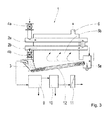
- FIG. 1 shows a conventional wood gasification plant 30 according to the prior art.
- a wood gasification plant 30 In such a plant mostly wood chips are introduced from above into a shaft 31 and gassed by supplying heat energy. The result is a bed in the area 32, which slowly slips vertically downwards, because the wood gasifies and thereby decomposes into ash, coal and gas. Above, the wood is preheated. In the middle of the bed is the combustion chamber 33. Here is ambient air 34 supplied. It burns a part of the wood at about 1000 ° C. The result is a mixture of wood gas and flue gases with a lot of nitrogen and carbon dioxide. The gas is sucked off at 35.
- FIG. 2 shows a schematic representation of a first embodiment of the biomass gasification plant. Via a cellular wheel 4a, which serves as a lock, biomass enters the upper transverse conveyor designed as a screw 2a.
- the biomaterial is air-tightly transported separately from a combustion chamber 5b through this combustion chamber 5b.
- the biomass is preheated by the flue gases and / or directly by flames arising in the combustion chamber 5a.
- the outer tube of the screw serves as a heat exchanger and is designed accordingly.
- the preheating screw 2a has a temperature of 100 to 500 degrees Celsius on its surface (outside).
- a downpipe is arranged, via which the preheated biomass falls into an underlying gasification screw 2b.
- the biomass is further airtight from the furnace 5b through it.
- the gasification screw on its surface has a temperature between 700 and 900, preferably 800 degrees Celsius.
- the gasification takes place in the screw 2b.
- At the end of the gasification screw 2b there is another cellular wheel 4b, which the gasification screw 2b as a lock of a downstream reduction chamber 3 separates. In this reduction chamber 3 fall the non-gasified residues of biomass, especially glowing charcoal.
- this creates a bed of glowing charcoal, through which the wood gas is sucked out of the gasification.
- carbon dioxide is reduced here, whereby the quality of the gas is significantly increased.
- the corresponding upgraded gas flows after the reduction chamber 3 in a first stage 9 of the cooling system and then in a second stage 10 of the cooling system and then by a police filter 11. Thereafter, the gas is recoverable.
- FIG. 2 shown biomass gasification plant 1 differs from the in FIG. 3 shown system only in the principle of firing: While in the plant after FIG. 2 Fuel is only given from the outside into the combustion chamber 5a and is burned with the addition of air, the combustion chamber 5a according to FIG. 3 additionally connected via a coal screw 12 with the reduction space 3. This results in a large saving of fuel, because the combustion chamber 5 a can be fired after starting the system almost or completely completely with the non-gasified residues from the gasification screw 2 b.
- FIGS. 4a to 4d Further details of a particular embodiment of the biomass gasification plant 1 are shown in various cross-sectional views.
- two metering devices 26a and 26b are arranged, one of which supplies the biomass in the container 19 to the preheating screw 2a and the other supplies the combustion chamber 5a with biomass.
- the container 19 was in turn with a pneumatic conveyor or mechanically filled via the inlet 20. The air of this filling escapes at outlet 21.
- two sensors 22 and 23 are arranged, which monitor the filling of the container 19 with biomass.
- an ejector for ash 25 is provided, for which a screw 24 is also provided.
- the crude gas is sucked off at 13 and has a temperature of about 500 degrees Celsius.
- the combustion chamber 5a has a length of about 4 meters, a width and height of about one meter.
- the preheating screw 2a and the gasification screw 2b each have a length of 4 meters and an outer diameter of 30 cm.
- the total height of the plant including container 19 for biomass is about 5 meters.
- the plant is an embodiment of the biomass gasification plant is shown, in which the heat transfer device 5a, 5b, the heat partially off indirectly to the gasification screw 2b and the preheating screw 2a.
- firebricks 27 chambers are formed in which the gasification screw 2b and the preheating screw 2a rest. This ensures that the fireclay bricks serve as a heat storage and give the heat evenly to the two screws. As a result, not only the efficiency of the system is increased, but it also prevents sagging and bending of the screw.
- the biomass gasification plant is designed so that the firebrick stones protecting the gasification screw 2b become about 1000 degrees Celsius warm and the firebrick stones protecting the preheating screw become about 600 degrees Celsius warm.
- FIG. 6 Further details of an embodiment of the biomass gasification plant are shown.
- the resulting in the combustion chamber 5a flue gases are passed through the combustion chamber 5b to the transport devices (2 screws) by means of pipe 6 in a cooler.
- the cooler also has a dust collector.
- the temperature of the flue gas is lowered from 500 degrees Celsius to about 100 degrees Celsius.
- Via a fan 17 then reach the flue gases to a chimney 18 for the flue gas.
- the extracted via the pipe 13 from the gasification screw 2b wood gas passes through two successive connected two-stage cooler 9, 10, in which the wood gas cooled from about 500 degrees Celsius to between 0 and 20 degrees Celsius and preferably to 5 degrees Celsius and with a dust collector 11th is filtered to a gas engine 14 and a connected generator 15 with 100 KW.
- the metering device 26a is put into operation, passes through the biomass by means of a screw conveyor into the combustion chamber 5a and is burned there.
- the heat of combustion is transmitted via the flue gases and the fireclay heat storage to the transport device and heated it.
- the outer wall of the transport device has reached a temperature of 750 degrees Celsius, the gasification process begins.
- the metering device 26b which is connected to a screw conveyor for filling the preheating screw 2a, is opened.
Abstract
Die vorliegende Erfindung betrifft die Erzeugung von brennbarem Gas aus Biomasse durch Vergasung, und betrifft insbesondere eine Biomassevergasungsanlage (1) und ein Verfahren zur Erzeugung von Gas in einer Biomassevergasungsanlage (1) sowie ein Verbundsystem zur Erzeugung von Strom. Um die Erzeugung von brennbarem Gas zu verbessern, ist eine Biomassevergasungsanlage (1) vorgesehen, die eine Transportvorrichtung (2a, 2b) von Biomasse, z.B. Holzhackschnitzel (selten auch andere Biomasse) aufweist, sowie eine Wärmezufuhrvorrichtung zur Erwärmung der im Innenbereich der Transportvorrichtung (2a, 2b) angeordneten Biomasse, und eine Abführvorrichtung (13)zum Abführen des entstehenden Gases, wobei die Absaugvorrichtung (13)unterhalb der Transportvorrichtung vorgesehen ist.The present invention relates to the production of combustible gas from biomass by gasification, and more particularly relates to a biomass gasification plant (1) and a process for producing gas in a biomass gasification plant (1) and a composite system for generating electricity. In order to improve the production of combustible gas, a biomass gasification plant (1) is provided which comprises a transport device (2a, 2b) of biomass, e.g. Has wood chips (rarely other biomass), and a heat supply device for heating the interior of the transport device (2a, 2b) arranged biomass, and a discharge device (13) for discharging the resulting gas, wherein the suction device (13) is provided below the transport device ,
Description
Die vorliegende Erfindung betrifft die Erzeugung von gereinigtem brennbarem Gas mit hohem Brennwert aus Biomasse durch Vergasung, und betrifft insbesondere eine Biomassevergasungsanlage und ein Verfahren zur Erzeugung von Gas in einer Biomassevergasungsanlage.The present invention relates to the production of purified high-calorie flammable gas from biomass by gasification, and more particularly to a biomass gasification plant and a gas-producing process in a biomass gasification plant.
Biomassevergaser werden verwendet, um aus Biomasse brennbares Gas zu gewinnen, beispielsweise zur Einspeisung in ein Gasnetz, zur Speicherung in einem Gasspeicher, zum Antrieb eines Gasmotors, der z.B. als Antrieb für ein Fahrzeug oder als Antrieb zur Erzeugung elektrischer Energie Verwendung findet. Bei Biomassevergasern werden Holzhackschnitzel (seltener auch andere Biomasse) z.B. von oben in einen Schacht eingebracht und durch Zufuhr von Wärmeenergie vergast. Es entsteht eine Schüttung, die langsam senkrecht nach unten rutscht, weil das Holz vergast und dabei in Asche, Kohle und Gas zerfällt. Wenn Holz mit schlechter Qualität zugeführt wird und bei zu viel Feinstoffen wie Sägespänen kann es jedoch zu einer Fehlfunktion oder gar einem Ausfall der Anlage kommen. Oben wird das Holz vorgewärmt. In der Mitte der Schüttung ist der Brennraum. Hier wird Umgebungsluft zugeführt. Dabei verbrennt ein Teil des Holzes bei ca. 1000°C. Es entsteht ein Gemisch aus Holzgas und Rauchgasen die viel Stickstoff und Kohlendioxid enthalten. Das Kohlendioxid ist unerwünscht und deshalb wird das entstehende Gas unten (nicht oben) abgesaugt. Das Gas muss dabei an den glühenden unvergasten Reststoffen (Hauptbestandteil Holzkohle) vorbei und ein Teil des unbrennbaren C02 wird dabei zu brennbarem CO reduziert. Dadurch wird die schlechte Qualität des so entstandenen Holzgases etwas verbessert. Der hohe Gehalt an störendem, unbrennbarem Stickstoff kann so aber nicht entfernt werden.Biomass gasifiers are used to extract combustible gas from biomass, for example for feeding into a gas network, for storage in a gas storage, for driving a gas engine, which is used, for example, as a drive for a vehicle or as a drive for generating electrical energy. In biomass gasifiers, wood chips (and less commonly other biomass) are introduced from above into a shaft and gasified by the supply of heat energy. The result is a bed of material that slowly slips down vertically because the wood gasifies and decomposes into ashes, coal and gas. When supplied with poor quality wood and too much fines such as sawdust can lead to a malfunction or even failure of the system. Above, the wood is preheated. In the middle of the bed is the combustion chamber. Here ambient air is supplied. It burns a part of the wood at about 1000 ° C. The result is a mixture of wood gas and flue gases containing a lot of nitrogen and carbon dioxide. The carbon dioxide is undesirable and therefore the resulting gas is sucked down (not above). The gas must thereby pass the glowing non-gassed residues (main constituent charcoal) and part of the incombustible CO 2 is thereby reduced to combustible CO. This slightly improves the poor quality of the resulting wood gas. However, the high level of interfering, incombustible nitrogen can not be removed.
Es besteht daher ein Bedarf für die Verbesserung einer Biomassevergasungsanlage.There is therefore a need for the improvement of a biomass gasification plant.
Diese Aufgabe wird durch eine Biomassevergasungsanlage, ein Verfahren zur Erzeugung, Nachbehandlung und Reinigung von Gas in einer Biomassevergasungsanlage sowie ein Verbundsystem zur Erzeugung von Strom mit einer Biomassevergasungsanlage nach einem der unabhängigen Ansprüche erreicht. Beispielhafte Ausführungsformen sind in den abhängigen Ansprüchen dargestellt.This object is achieved by a biomass gasification plant, a process for the production, aftertreatment and purification of gas in a biomass gasification plant and a composite system for the production of electricity with a biomass gasification plant according to one of the independent claims. Exemplary embodiments are presented in the dependent claims.
Gemäß der vorliegenden Erfindung wird eine Biomassevergasungsanlage vorgeschlagen, welche über
eine Transportvorrichtung von Biomasse und eine Wärmezufuhrvorrichtung zur Erwärmung der im Innenbereich der Transportvorrichtung transportierten Biomasse verfügt, wobei die Transportvorrichtung von Biomasse luftdicht von der Wärmezufuhrvorrichtung getrennt im Inneren der Wärmezufuhrvorrichtung angeordnet ist und selbst als Wärmeübertrager ausgebildet ist, wobei die im Inneren der Wärmezufuhrvorrichtung angeordnete Transportvorrichtung eine vergasungsleistungsspezifische Wärmeübertrager-Oberfläche zur Erzeugung von Gas aus Biomasse von wenigstens 0,04 m2/ (Nm3 pro h)und bevorzugt wenigstens 0,08 m2/ (Nm3 pro h) besitzt.According to the present invention, a biomass gasification plant is proposed which over
a biomass transport device and a heat supply device for heating the transported in the interior of the transport device biomass, said Transport device of biomass is arranged airtightly separated from the heat supply device in the interior of the heat supply device and is itself designed as a heat exchanger, wherein arranged in the interior of the heat supply device transport device a gasification power specific heat exchanger surface for generating gas from biomass of at least 0.04 m 2 / (Nm 3 per h) and preferably at least 0.08 m 2 / (Nm 3 per h).
Vorzugsweise ist je eine Absaugvorrichtung vorgesehen, welche das entstehende Gas und Rauchgas getrennt voneinander abführt und im Inneren der Transportvorrichtung für Biomasse und im Inneren der Wärmezufuhrvorrichtung jeweils ein Unterdruck erzeugt. Die Rauchgase werden getrennt über einen normalen Schornstein in die Umgebung abgeleitet.Preferably, a respective suction device is provided, which discharges the gas and flue gas formed separately from each other and in each case generates a negative pressure inside the transport device for biomass and inside the heat supply device. The flue gases are discharged separately via a normal chimney into the environment.
Vorzugsweise ist die Biomassevergasungsanlage so ausgestaltet, dass das Gas durch die glühenden, unvergasten Reststoffe führbar ist, um einen Teil des unbrennbaren CO2 zu brennbarem CO zu reduzieren.Preferably, the biomass gasification plant is designed so that the gas can be passed through the glowing, non-gassed residues to reduce a portion of the incombustible CO2 to combustible CO.
Zusätzlich werden dabei in dem Rohgas noch vorhandene Bestandteile wie Schwefel und Teer zerstört. Dadurch wird die bereits gute Qualität des so entstandenen Holzgases noch verbessert. Das ist auch sehr vorteilhaft, wenn das Gas zur Verwendung in einem Gasmotor vorgesehen ist, da diese Bestandteile einem Gasmotor oder Gasbrenner schaden können.In addition, in the raw gas still existing components such as sulfur and tar are destroyed. This improves the already good quality of the resulting wood gas. This is also very advantageous when the gas is intended for use in a gas engine, as these components can damage a gas engine or gas burner.
Gemäß einer bevorzugten Ausführungsform kommt der Teil der Transportvorrichtung, in welchem die Vergasung stattfindet, ohne zusätzliche Verbrennungsluft aus.According to a preferred embodiment, the part of the transport device in which the gasification takes place without additional combustion air.
Vorzugsweise ist die Biomassevergasungsanlage so ausgebildet, dass die Vergasung in offenen Transportvorrichtungen erfolgt; und/oder die Vergasung in temperaturbeständigen Transportvorrichtungen erfolgt, die liegend oder stehend aufgestellt sind.Preferably, the biomass gasification plant is designed so that the gasification takes place in open transport devices; and / or the gasification takes place in temperature-resistant transport devices that are placed lying or standing.
In einem Beispiel ist vorgesehen, dass die Transportvorrichtungen von außen beheizt werden. Durch die Transportvorrichtungen wird gleichzeitig bevorzugt kontinuierlich (auch chargenweiser Transport möglich) die Biomasse transportiert und dabei vergast. Die Wärmeübertragung erfolgt durch die Wand der Transportvorrichtung von der sie umschließenden Wärmezufuhrvorrichtung aus.In one example, it is provided that the transport devices are heated from the outside. By the transport devices is preferably at the same time continuously (also batchwise transport possible), the biomass transported and thereby gasified. The heat transfer takes place through the wall of the transport device from the heat supply device surrounding it.
Vorzugsweise ist die Transportvorrichtung als wenigstens ein Querförderer, z.B. eine Schneckenfördereinrichtung ausgelegt, welcher so ausgebildet und angeordnet ist, dass eine Erwärmung und Vergasung nicht nur punktuell sondern entlang nahezu der gesamten Oberfläche der Transportvorrichtung, die innerhalb der Wärmezufuhrvorrichtung angeordnet ist. Bevorzugt ist dies eine Strecke von mindestens 2 Metern, noch mehr bevorzugt aber die gesamte Oberfläche der Transportvorrichtung, wobei die Transportvorrichtung selbst als Wärmeübertrager ausgelegt ist.Preferably, the transport device is designed as at least one transverse conveyor, for example a screw conveyor, which is designed and arranged such that heating and gasification not only at points but along almost the entire surface of the transport device, which is arranged within the heat supply device. This is preferably a distance of at least 2 meters, more preferably, however, the entire surface of the transport device, wherein the transport device itself is designed as a heat exchanger.
Bei Biomassevergasungsanlagen, welche zur Erzeugung von Holzgas ausgelegt sind, mit dem ein Gasmotor z. B. mit einem 100KW Generator betrieben werden soll und in welchen im Regelbetriebsfall ein Biomassenstrom von 40 bis 100 kg/h zur Vergasung zugeführt werden soll besitzt die als Wärmeübertrager ausgelegte Transportvorrichtung vorzugsweise eine biomassenstromspezifische Oberfläche (außen) von mehr als 0,05 m2/ (Kg pro h).In biomass gasification plants, which are designed for the production of wood gas, with a gas engine z. B. is to be operated with a 100KW generator and in which a biomass flow of 40 to 100 kg / h is to be supplied for gasification in the regular operation, designed as a heat transfer device preferably has a biomass flow-specific surface (outside) of more than 0.05 m 2 / (Kg per h).
Im Gegensatz zu Anlagen mit lokal stark begrenzten Vergasungs-Spots hat sich überraschender Weise gezeigt, dass hierdurch der Gesamtwirkungsgrad einer Biomassevergasungsanlage gesteigert werden kann.In contrast to systems with locally very limited gasification spots has surprisingly been found that this can increase the overall efficiency of a biomass gasification plant.
Abgesehen vom Anfahren des Prozesses hat sich gezeigt, dass die zur Vergasung notwendige Wärmezufuhr zum Vergasen der Biomasse der Transportvorrichtung alleine durch die Verbrennung der nicht vergasten Bestandteile ausreichend ist. Dazu werden die nicht vergasten Bestandteile der Biomasse (Hauptbestandteil ist Holzkohle)aus der Transportvorrichtung in die Brennkammer überführt.Apart from the start of the process, it has been found that the heat input necessary for the gasification to gasify the biomass of the transport device is sufficient solely by the combustion of the non-gasified constituents. For this purpose, the non-gasified components of the biomass (main component is charcoal) are transferred from the transport device into the combustion chamber.
Die Biomasse kann in die Transportvorrichtung kontinuierlich oder auch chargenweise eingebracht werden.The biomass can be introduced into the transport device continuously or batchwise.
Dabei wird die Verbrennungswärme auf die Transportvorrichtung übertragen, was die Vergasung im Innern der der Transportvorrichtung auslöst.The combustion heat is transferred to the transport device, which triggers the gasification in the interior of the transport device.
Es hat sich herausgestellt, dass die als Wärmeübertrager ausgebildete Transportvorrichtung besonders lange hält, wenn eine Erwärmung entlang möglichst der gesamten Länge der Transportvorrichtung innerhalb der Wärmezufuhrvorrichtung erfolgt. Bevorzugt ist ein Großteil der Länge der Transportvorrichtung, welche bevorzugt als Schnecke ausgelegt ist, in der Wärmezufuhrvorrichtung angeordnet, wobei die Temperatur der Transportvorrichtung zwischen 700 und 900, weiter bevorzugt zwischen 750 und 850 und noch weiter bevorzugt bei genau 800 Grad Celsius gehalten wird.It has been found that the designed as a heat exchanger transport device holds particularly long, if a heating along as far as possible the entire length of the transport device within the heat supply device takes place. Preferably, a major part of the length of the transport device, which is preferably designed as a screw, is arranged in the heat supply device, the temperature of the transport device being kept between 700 and 900, more preferably between 750 and 850 and even more preferably at exactly 800 degrees Celsius.
Gemäß einer weiteren, besonders bevorzugten Ausführungsform sind zwei Querförderer, vorzugsweise zwei Schnecken vorgesehen, wobei der erste, obere Querförderer dazu ausgelegt ist, eine Vorwärmung der Biomasse durchzuführen und der zweite, untere Querförderer dazu ausgelegt ist, eine Vergasung der Biomasse durchzuführen. Eine Vorwärmung erfolgt bei vorzugsweise 100 bis 500 Grad Celsius.According to a further, particularly preferred embodiment, two transverse conveyors, preferably two screws are provided, wherein the first, upper transverse conveyor is designed to perform a preheating of the biomass and the second, lower transverse conveyor is adapted to perform a gasification of the biomass. A preheating takes place at preferably 100 to 500 degrees Celsius.
Vor der Schnecke ist in einem Beispiel eine Dosiereinrichtung installiert. In einem anderen Beispiel ist die Dosiereinrichtung nicht vorgesehen.In front of the screw, in one example, a metering device is installed. In another example, the metering device is not provided.
Es entsteht im Betrieb der Schnecke eine lose Schüttung, die nur einen Teil des Innenraumes der Schnecken ausfüllt und ständig umgewälzt wird. Dadurch kann die Biomasse leichter und gleichmäßiger erwärmt werden und vergast so besser. Im Inneren der Vergasungsschnecke vergast die Biomasse und zerfällt dabei in Asche, Kohle und Gas. Auch Biomasse mit schlechter Qualität und Biomasse mit noch Feinstoffen, wie Sägespäne kann so problemlos vergast werden.During operation of the screw, a loose bed is formed, which fills only part of the interior of the screws and is constantly circulated. This allows the biomass to be heated more easily and more uniformly and gasifies better. Inside the gasification screw, the biomass gasifies and decomposes into ashes, coal and gas. Also biomass with poor quality and biomass with even fines, such as sawdust can be gasified so easily.
Gemäß einer weiteren, bevorzugten Ausführungsform ist die Transportvorrichtung für Biomasse bevorzugt also die zwei Querförderschnecken wenigstens teilweise von einer direkten Wärmezuführung durch eine Trennwand abgeschottet, sodass die Wärme zumindest teilweise indirekt über die Abschottung erfolgt, welche bevorzugt aus Schamottesteinen gebildet ist.According to a further preferred embodiment, the biomass transport device is therefore preferably the two Querförderschnecken at least partially sealed off by a direct heat supply through a partition so that the heat is at least partially indirectly via the partition, which is preferably formed from firebricks.
Gemäß einer Ausführungsform sind durch Schamottesteine Kammern gebildet, in denen die Transportvorrichtung eingebracht ist. Bei der Ausführungsform mit zwei Querförderschnecken sind bevorzugt zwei separate Kammern vorgesehen, in welchen jeweils eine der Querförderschnecken angeordnet ist, wobei in den Kammern unterschiedliche Temperaturen herrschen. Die Schamottesteine nehmen die Wärme von der Wärmezufuhrvorrichtung (unter den Kammern gelegen) auf und geben diese gleichmäßig auf die zwei Querförderschnecken ab.According to one embodiment, chambers are formed by firebricks, in which the transport device is introduced. In the embodiment with two transverse screw conveyors, two separate chambers are preferably provided, in each of which one of the transverse screw conveyors is arranged, wherein different temperatures prevail in the chambers. The firebricks absorb the heat from the heat supply device (located under the chambers) and distribute it evenly on the two transverse augers.
Durch diese indirekte Wärmeübertragung wird sichergestellt, dass die Wärmeübertragung auf die Außenwand der Querschnecken gleichmäßig erfolgt und sich kurzfristige Änderungen bei der Wärmezuführung dank der Speichermasse "Schamotte" nicht schädlich auswirken. Es hat sich gezeigt, dass diese Gleichmäßigkeit der Wärmeübertragung ein im Stand der Technik unterschätzte Auswirkung auf den Vergasungsprozess hat. Auf diese Weise wird der Vorwärmprozess und der Vergasungsprozess auch vergleichmäßigt. Dadurch ist zudem sichergestellt, dass die Außenwand der zwei Querförderschnecken sich nicht durch lokale Überhitzung oder Abkühlung verspannen kann und sich die zwei Querförderschnecken verziehen (verbiegen) und dadurch unbrauchbar werden.This indirect heat transfer ensures that the heat transfer to the outer wall of the transverse screws takes place uniformly and that short-term changes in the heat supply do not have a detrimental effect, thanks to the "chamotte" storage mass. It has been found that this uniformity of heat transfer has an underestimated effect on the gasification process in the prior art. In this way the preheating process and the gasification process are also made uniform. This also ensures that the outer wall of the two transverse screw conveyors can not be tense by local overheating or cooling and the two transverse screw conveyors warp (bend) and thus become unusable.
Zusätzlich werden die zwei Querförderschnecken auf dem stabilen Boden der Schamottekammer lose aufgelegt. Das gesamte Gewicht der zwei Querförderschnecken lastet so auf der Schamotte und entlastet die Querförderschnecken. Damit wird dem "Durchhängen" vorgebeugt. Die zwei Querförderschnecken verbiegen sich nicht und können sich ungehindert ausdehnen. Sie werden so nicht unbrauchbar.In addition, the two transverse screw conveyors are placed loosely on the stable floor of the chamotte chamber. The entire weight The two transverse augers load on the fireclay and relieve the cross auger. This prevents "sagging". The two transverse augers do not bend and can expand unhindered. They will not be useless.
Die Wärmeübertragung innerhalb der Querschnecken wird auch dadurch verbessert, dass die Biomasse in den zwei Querförderschnecken ständig umgewälzt wird.The heat transfer within the transverse screws is also improved by the fact that the biomass in the two transverse screw conveyors is constantly circulated.
Gemäß einer Ausführung ist die Transportvorrichtung von Biomasse mit der Wärmezufuhrvorrichtung derart verbunden und dazu ausgelegt, dass die nach der Vergasung verbleibende Biomasse in die Brennkammer der Wärmezufuhrvorrichtung befördert wird, welche ihrerseits dazu ausgelegt ist, nach einer Anlaufphase (vorheizen) und bei einem Betrieb mit beispielsweise Holzhackschnitzeln die zur Erwärmung und Vergasung von der Biomasse notwendige Energie nahezu vollständig oder vollständig (je nach Brennwert) über die Versorgung mit der nach der Vergasung verbleibenden unvergaste Reste(Holzkohle)der Hackschnitzel zu beziehen. Es hat sich gezeigt, dass diese besonders wünschenswerte Eigenschaft nur ermöglicht wird, wenn eine Vergasung und/oder eine Vorwärmung nicht punktuell oder in einem kleinem Bereich erfolgt, sondern über eine Förderstrecke der Transportvorrichtung von wenigsten 2 Metern, weiter bevorzugt der gesamten Oberfläche der Transportvorrichtung.According to one embodiment, the transport device of biomass is connected to the heat supply device and designed so that the biomass remaining after gasification is conveyed into the combustion chamber of the heat supply device, which in turn is designed to (preheat) after a start-up phase and during operation with, for example Holzhackschnitzeln the energy required for heating and gasification of the biomass almost completely or completely (depending on the calorific value) on the supply of the remaining after gasification remains (charcoal) of wood chips. It has been found that this particularly desirable property is only possible when gasification and / or preheating is not punctiform or in a small area, but over a conveyor line of the transport device of at least 2 meters, more preferably the entire surface of the transport device.
Der Heizvorgang ist jedoch vom Vorgang der Vergasung getrennt. Deshalb sind in einem anderen Beispiel andere Energiequellen wie Gas, Öl oder Strom vorgesehen. Es muss nur genügend Wärme zur Vergasung bereitgestellt werden.However, the heating process is separate from the gasification process. Therefore, in another example, other sources of energy such as gas, oil or electricity are provided. Only enough heat must be provided for gasification.
Bevorzugt wird am Anfang der Transportvorrichtung die Biomasse vorgewärmt. Im hinteren Teil bei ca. 800°C erfolgt der Vergasungsvorgang. Weil bei der Vergasung in einem Beispiel keine zusätzliche Verbrennungsluft zugeführt wird, ist der Anteil an brennbaren Gasen sehr hoch. Stickstoff ist nahezu nicht enthalten. Der Anteil von unbrennbarem CO2 ist gering.Preferably, the biomass is preheated at the beginning of the transport device. In the rear part at about 800 ° C, the gasification process takes place. Because the gasification in an example, no additional combustion air is supplied, the proportion of combustible gases is very high. Nitrogen is almost not included. The proportion of incombustible CO2 is low.
Der CO2-Anteil kann weiter reduziert werden, wenn das Gas, wie in einer Ausführungsform vorgeschlagen, durch die glühenden nicht-vergasten Reststoffe (Hauptbestandteil Holzkohle) geführt wird. Ein Teil des unbrennbaren CO2 wird dabei zu brennbarem CO reduziert. Zusätzlich wird dabei ein Teil der für einen Gasmotor schädlichen Bestandteile wie Schwefel und Teer zerstört. Dadurch wird die bereits gute Qualität des so entstandenen Holzgases noch verbessert.The proportion of CO2 can be further reduced if the gas, as proposed in one embodiment, is passed through the glowing non-gasified residues (main constituent of charcoal). Part of the incombustible CO2 is reduced to combustible CO. In addition, part of the components harmful to a gas engine, such as sulfur and tar, are destroyed. This improves the already good quality of the resulting wood gas.
Zur Verbesserung der Sicherheit wird in einem Beispiel am Eintrag (Anfang) und Austrag (Ende) der Schnecken eine Schleuse installiert, z.B. eine Zellenrad- oder Behälterschleuse. Auf diese Weise kann bei einer Havarie verhindert werden, dass ggf. giftiges und brennbares Gas austritt.To improve safety, in one example, at the entry (start) and discharge (end) of the screws, a lock is installed, e.g. a cellular wheel or container lock. In this way, it can be prevented in the event of an accident that potentially toxic and combustible gas escapes.
Die entstehenden Holzgase werden im Betriebszustand abgesaugt. Dabei entsteht im Reaktor ein Unterdruck.The resulting wood gases are extracted during operation. This creates a negative pressure in the reactor.
Alternativ kann die Vergasung aber auch in offenen Transportvorrichtungen erfolgen.Alternatively, the gasification can also be done in open transport devices.
Gemäß einer Ausführungsform kann am Ende der Transportvorrichtung ein Reduktionsbehälter für die nicht-erwünschten Gasbestandteile wie Kohlendioxid (CO2), Teer und Schwefel vorgesehen sein, welcher dazu ausgebildet ist, die glühende Holzkohle aufzufangen und eine Schüttung bereit zu stellen, die eine Veredelung des Gases durch das Durchführen der Rohgase durch die glühenden Holzkohlen verbessert. An diesen Reduktionsbehälter sind gemäß bestimmten Ausführungsformen Einlässe vorgesehen, die ein Einbringen von Zusatzstoffen, wie Wasser, oder Kalk ermöglichen. Durch das Einbringen dieser Stoffe werden die Gasqualität und der Brennwert des Rohgases weiter gesteigert.According to one embodiment, at the end of the transport device, a reduction vessel may be provided for the non-desired gas constituents, such as carbon dioxide (CO 2 ), tar and sulfur, which is designed to be glowing To collect charcoal and to provide a bedding, which improves a refining of the gas by passing the raw gases through the glowing charcoal. At this reduction tank inlets are provided according to certain embodiments, which allow the introduction of additives such as water or lime. By introducing these substances, the gas quality and the calorific value of the raw gas are further increased.
Gemäß einer Ausführungsform erfolgt die Gasabführung am Ende der Transportvorrichtung. Im Falle einer Schnecke bevorzugt am Ende der Förderstrecke der Schnecke am Austragsstutzen der Schnecke.According to one embodiment, the gas removal takes place at the end of the transport device. In the case of a screw preferred at the end of the conveying path of the screw on the discharge nozzle of the screw.
Gemäß einer weiteren Ausführungsform besitzt die Anlage eine Vorrichtung zur Zugabe von Wasser. Hierdurch erhöht sich der Wasserstoff- und Methangehalt im Rohgas.According to a further embodiment, the plant has a device for adding water. This increases the hydrogen and methane content in the raw gas.
Vorzugsweise ist ebenfalls oder fakultativ eine Vorrichtung zur Zugabe von Kalk vorgesehen. Hierdurch wird der Schwefelgehalt im Rohgas und in der Asche reduziert.Preferably, also or optionally, a device for adding lime is provided. This reduces the sulfur content in the raw gas and in the ash.
Die heißen brennbaren Gase, die in der vorliegenden Erfindung auch als Holzgas bezeichnet werden, werden in einem Beispiel mit ca. 500 bis 600°C aus der Schnecke abgesaugt und durch einen auf dem Prinzip eines Wärmetauschers beruhenden Kühler mit Polizeinachfilter mit oder ohne Aktivkoksfüllung geführt. Die Kühlung und Reinigung erfolgt z.B. um ggf. noch vorhandene schädliche Stoffe wie Teer, Schwefel und Staub abzuscheiden. Dies stellt eine weitere Verbesserung der Qualität des Rohgases dar und führt zu einer Verlängerung der Lebensdauer eines mit dem dann gereinigten Gas betriebenen Motors.The hot combustible gases, which are also referred to in the present invention as wood gas, are sucked in an example of about 500 to 600 ° C from the screw and passed through a based on the principle of a heat exchanger cooler with police after-filter with or without Aktivkoksfüllung. The cooling and cleaning is done, for example, to remove any remaining harmful substances such as tar, sulfur and dust. This represents a further improvement in the quality of the Raw gas and leads to an extension of the life of a then operated with the purified gas engine.
Gemäß einer weiteren bevorzugten Ausführungsform wird die erste Stufe des zweistufigen Kühlers mit Polizeifilter durch einen Gaswäscher ersetzt. Der Gaswäscher hat die Aufgabe, das Rohgas mittels eingespritztem Kühlwasser abzukühlen. Das Rohgas kommt dabei mit dem Kühlmedium in Kontakt. Dabei wird das Rohgas von unten im Gaswäscher mittels Düsenboden oder Siebboden direkt durch das aufgestaute Kühlwasser geleitet. Das Rohgas wird dabei in einzelne Gasblasen aufgelöst, die durch das stehende Kühlwasser und mittels Sprühdüsen befeuchteter hohler Füllkörper nach oben steigen. Dabei hat das Rohgas intensiven Kontakt mit dem Kühlwasser und ggf. dem Kühlwasser zugeführten Additiven. Dem Kühlwasser können verschiedene Additive wie Kalkmilch und Säure oder Basen bindende Substanzen beigemischt werden. Diese können dann ggf. im Rohgas enthaltene Schadstoffe binden und werden zusammen mit dem Kühlwasser ausgetragen. Die zweite Stufe des Kühlers hat (wie im ersten Ausführungsbeispiel) die Aufgabe, das dem Rohgas im Gaswäscher zugeführte Wasser wieder abzuscheiden und das Rohgas noch weiter herunter zu kühlen. Zusätzlich wird das Rohgas durch einen Polizeifilter geleitet und gefiltert. Das so behandelte Rohgas kann einem Gasmotor zugeführt werden.According to a further preferred embodiment, the first stage of the two-stage cooler with police filter is replaced by a gas scrubber. The gas scrubber has the task of cooling the raw gas by means of injected cooling water. The raw gas comes into contact with the cooling medium. The raw gas is passed from below in the gas scrubber by means of nozzle bottom or sieve plate directly through the pent-up cooling water. The raw gas is dissolved into individual gas bubbles, which rise by the standing cooling water and by means of spray nozzles moistened hollow packing upwards. The raw gas has intensive contact with the cooling water and possibly the cooling water supplied additives. The cooling water, various additives such as milk of lime and acid or base-binding substances are added. These can then possibly bind pollutants contained in the raw gas and are discharged together with the cooling water. The second stage of the cooler has (as in the first embodiment) the task to deposit the raw gas in the gas scrubber supplied water again and to cool down the raw gas even further. In addition, the raw gas is passed through a police filter and filtered. The raw gas thus treated can be supplied to a gas engine.
Das gereinigte Gas kann von einem handelsüblichen Stromerzeuger, z.B. Gasmotor mit Generator, als Kraftstoff verwendet werden. Der entstehende Strom, in einem Beispiel ca. 100 kW/h, kann verkauft oder selbst genutzt werden.The purified gas can be used by a commercial power generator, eg gas engine with generator as fuel. The resulting electricity, in one example about 100 kW / h, can be sold or used by yourself.
Beim Betrieb der Anlage wird zusätzlich zum Strom Wärme erzeugt. Diese Wärme von ca. 250 kW/h, die hier als Nebenprodukt anfällt, kann verkauft oder selbst genutzt werden.When operating the system, heat is generated in addition to the electricity. This heat of approx. 250 kW / h, which is a by-product here, can be sold or used by the customer.
In einem Beispiel ist vorgesehen, dass die Transportvorrichtung von der Flamme eines Brennraums direkt beheizt werden oder von Rauchgasen verbrannter Biomasse (z.B. Holz) im Gegen-, Gleich- oder Kreuzstrom umspült werden und dabei beheizt werden. Das Reaktionsprodukt Holzkohle aus den Reaktoren wird direkt (z.B. ungekühlt oder auch nach Abkühlung) als Brennstoff in den Brennraum überführt. Das reduziert die Heizkosten.In one example, it is provided that the transport device are directly heated by the flame of a combustion chamber or are flushed with countercurrent, co-current or cross-flow of flue gases of burnt biomass (for example wood) and heated thereby. The reaction product charcoal from the reactors is transferred directly (e.g., uncooled or even after cooling) as fuel into the combustion chamber. This reduces the heating costs.
In einem Beispiel ist vorgesehen, dass das Reaktionsprodukt Rohgas aus der Transportvorrichtung bzw. aus dem Reduktionsbehälter abgesaugt wird, auf Temperaturen unter oder nahe dem Gefrierpunkt gekühlt wird und gefiltert wird. Durch die starke Kühlung werden für den zu betreibenden Gasmotor schädliche Bestandteile wie Teer und Staub aus dem Gas entfernt. Erst dann wird das Gas dem Gasmotor zugeführt.In one example, it is provided that the reaction product raw gas is sucked out of the transport device or from the reduction vessel, is cooled to temperatures below or near freezing point and is filtered. The strong cooling removes harmful components such as tar and dust from the gas for the gas engine to be operated. Only then is the gas supplied to the gas engine.
Gemäß der Erfindung ist auch ein Verfahren zur Erzeugung von Gas in einer Biomassevergasungsanlage, sowie ein Verbundsystem zur Erzeugung von Strom vorgesehen, in dem eine voranstehend beschriebene Biomassevergasungsanlage angeordnet ist und welches zusätzlich über einen gasbetriebenen Motor und einen Generator zur Erzeugung von Strom verfügt.According to the invention, there is also provided a method for producing gas in a biomass gasification plant, and a composite system for generating electricity, in which a biomass gasification plant as described above is arranged and which additionally has a gas-powered engine and a generator for generating electricity.
Der Gasmotor erreicht durch die Kühlung eine höhere Leistung.
-
Fig. 1 zeigt eine Funktionsskizze einer herkömmlichen Biomassevergasungsanlage. -
Fig. 2 zeigt eine schematische Darstellung einer ersten Ausführungsform der erfindungsgemäßen Biomassevergasungsanlage. -
Figur 3 -
Figuren 4a bis 4d -
Figur 5 zeigt eine Biomassevergasungsanlage im Querschnitt mit den die Transportvorrichtung umschließenden Kammern aus Schamottesteinen für gleichmäßige Wärmezuführung und für die Abstützung der Transportvorrichtung, -
Figur 6
-
Fig. 1 shows a functional diagram of a conventional biomass gasification plant. -
Fig. 2 shows a schematic representation of a first embodiment of the biomass gasification plant according to the invention. -
FIG. 3 shows a schematic representation of a second embodiment of the biomass gasification plant. -
FIGS. 4a to 4d show details of the biomass feed and ash removal of the plant, -
FIG. 5 shows a biomass gasification plant in cross-section with the transport device enclosing chambers made of fireclay bricks for uniform heat supply and for supporting the transport device, -
FIG. 6 shows details of the wood gas treatment and a possible installation of the biomass gasification plant in a network system for power generation.
In diesen Schnecken 2a und 2b wird das Biomaterial Luftdicht getrennt von einem Feuerraum 5b durch diesen Feuerraum 5b transportiert. Auf dieser Strecke wird die Biomasse durch die Rauchgase und/oder direkt durch Flammen, welche in dem Brennraum 5a entstehen vorgewärmt. Dabei dient das Außenrohr der Schnecke als Wärmeübertrager und ist dementsprechend ausgelegt. Die Vorwärmschnecke 2a weist eine Temperatur von 100 bis 500 Grad Celsius an seiner Oberfläche (außen) auf. Am Ende dieser Vorwärmschnecke 2a ist ein Fallrohr angeordnet, über das die vorgewärmte Biomasse in eine darunter liegende Vergasungsschnecke 2b fällt. In der Vergasungsschnecke 2b wird die Biomasse weiter luftdicht von dem Feuerraum 5b durch diesen geführt. Während die Flamme im Feuerraum eine Temperatur von 900 bis 1100 bevorzugt 1000 Grad Celsius hat, hat die Vergasungsschnecke auf ihrer Oberfläche (außen) eine Temperatur zwischen 700 und 900, bevorzugt 800 Grad Celsius. Nicht nur auf einem kurzen Abschnitt der Schnecke, sondern auf einer Förderstrecke von bevorzugt mehr als 2 und noch mehr bevorzugt von mehr als 3 Metern bzw. der gesamten Länge der Schnecke 2b erfolgt die Vergasung in der Schnecke 2b. Am Ende der Vergasungsschnecke 2b befindet sich ein weiteres Zellenrad 4b, welches die Vergasungsschnecke 2b als Schleuse von einer nachgeordneten Reduktionskammer 3 trennt. In diese Reduktionskammer 3 fallen die nicht-vergasten Reste der Biomasse, insbesondere glühende Holzkohle. In der Reduktionskammer 3 entsteht so eine Schüttung aus glühender Holzkohle, durch die das Holzgas aus der Vergasung gesaugt wird. Während der Vergasung ggf. entstandenes Kohlendioxid wird hier reduziert, wodurch die Qualität des Gases erheblich gesteigert wird. Das dementsprechend aufgewertete Gas strömt nach der Reduktionskammer 3 in eine erste Stufe 9 der Kühlanlage und danach in eine zweite Stufe 10 der Kühlanlage und dann durch einen Polizeifilter 11. Danach ist das Gas verwertungsfähig.In these
Die Ausführungsform der in
In den
Der Brennraum 5a hat eine Länge von etwa 4 Metern, eine Breite und Höhe von etwa einem Meter. Die Vorwärmschnecke 2a und die Vergasungsschnecke 2b haben jeweils eine Länge von 4 Metern und einen Außen-Durchmesser von 30 cm. Die Gesamthöhe der Anlage inklusive Behälter 19 für Biomasse ist ca. 5 Meter.The
In der
In dieser bevorzugten Ausführungsform ist die Biomassevergasungsanlage so ausgelegt, dass die Schamottesteine, welche die Vergasungsschnecke 2b schützen, ca. 1000 Grad Celsius warm werden und die Schamottesteine, welche die Vorwärmschnecke schützen, ca. 600 Grad Celsius warm werden.In this preferred embodiment, the biomass gasification plant is designed so that the firebrick stones protecting the
In der
Zum Anfahren der Anlage gemäß der
Dazu wird die Dosiervorrichtung 26b, welche mit einer Förderschnecke zur Befüllung der Vorwärmschnecke 2a verbunden ist, geöffnet.For this purpose, the
Es hat sich gezeigt, dass es besonders sinnvoll ist, die Anlage so auszulegen, dass das beim Anfahren entstehende Holzgas im Anfahrprozess in den Brennraum 5a zu leiten, indem die Ventile zu den Kühlern 9 und 10 und über den Polizeifilter auch zu einer hier nicht dargestellten Fackel vorrübergehend geschlossen werden. Dann gelangt das entstehende Holzgas über die Kohleschnecke 12, welche sich am Ende der Vergasungsschnecke 2b befindet, in den Brennraum 5a. Daraufhin werden die beiden Kühler 9 und 10 eingeschaltet, wobei 9 ein Normal-Wasserkühler und 10 ein Eiswasserkühler ist. Die Temperatur im Brennraum unterhalb der Vergasungsschnecke 2b wird permanent überwacht. Der Anfahrprozess ist abgeschlossen, wenn die Temperatur über 799 Grad Celsius an der Oberfläche (Außenseite) der Transportvorrichtung steigt. Wenn hier mindestens 800 Grad Celsius herrschen und die Vorwärm- und Vergasungsschnecken wenigstens 60 Sekunden laufen, wird hochwertiges, für Gasmotoren verwertbares Gas produziert.It has been found that it is particularly expedient to design the plant so that the wood gas produced during startup can be guided into the
Beim Abfahren der Anlage wird die Vergasung gestoppt, wenn die Temperatur unter der Vergasungsschnecke unter 750 Grad Celsius fällt. Das dann noch produzierte Gas wird dann nicht wie beim Anfahren in den Brennraum 5a, sondern zu der hier nicht dargestellten Fackel geleitet.When the system is shut down, gasification stops when the temperature below the gasification screw falls below 750 degrees Celsius. The then still produced gas is then not directed as when starting in the
Claims (14)
wobei vor der Vorwärmschnecke (2a) eine Dosiereinrichtung (26a, 26b) installiert ist;
wobei eine lose Schüttung erzeugbar ist, die nur einen Teil des Innenraumes der Schnecken (2a,2b) ausfüllt, wodurch die Biomasse durch die im Inneren der Schnecke angeordnete sich drehende Schneckenwelle gut durchmischt, gleichmäßig vergast und in Asche, Kohle und Gas zerfällt;
wobei sich ein Wärmeerzeuger (5a, 5b) luftdicht getrennt vom Vorgang der Vergasung befindet, der mit Holz befeuerbar ist; wobei die Rauchgase getrennt über einen normalen Schornstein (18) in die Umgebung abgeleitet werden, wobei die Verbrennungswärme auf die Schnecken (2a, 2b) übertragbar ist, um die Vergasung im Innern der Schnecke (2b) auszulösen;
wobei der Heizvorgang vom Vorgang der Vergasung getrennt ist;
wobei am Anfang der Schnecke (2a) die Biomasse vorwärmbar ist und im hinteren Teil (2b) bei ca. 750°C bis 800°C die Vergasung stattfindet;
wobei die Vergasung ohne zusätzliche Verbrennungsluft durchführbar ist zur Erhöhung der Anteile an brennbaren Gasen;
wobei das Gas durch die glühenden nicht-vergasten Reststoffe führbar ist, um einen Teil des unbrennbaren CO2 zu brennbarem CO und Teer zu reduzieren;
wobei ein Teil der für einen Gasmotor (14) schädlichen Bestandteile wie schwefelhaltige Gase und Teer entfernbar ist; und
wobei am Eintrag (Anfang) und Austrag (Ende) der Schnecken (2a, 2b) eine Schleuse (4a, 4b) installiert ist, z.B. eine Zellenrad- oder Behälterschleuse, um ein Austreten von ggf. giftigem und brennbarem Gas bei einer Havarie zu verhindern.Biomass gasification plant (1) according to one of the preceding claims, wherein biomass with the transverse conveyor (2a, 2b) is continuously or batchwise introduced;
wherein a metering device (26a, 26b) is installed in front of the preheating screw (2a);
wherein a loose bed is generated, which fills only a part of the interior of the screw (2a, 2b), whereby the biomass well mixed by the arranged inside the screw rotating screw shaft, evenly gasified and decomposed into ash, coal and gas;
wherein a heat generator (5a, 5b) is airtightly separate from the process of gasification, which is combustible with wood; whereby the flue gases are discharged into the environment separately via a normal chimney (18), the heat of combustion being transferred to the screws (2a, 2a). 2b) is transferable to trigger the gasification inside the screw (2b);
wherein the heating process is separate from the gasification process;
wherein at the beginning of the screw (2a) the biomass is preheated and in the rear part (2b) at about 750 ° C to 800 ° C, the gasification takes place;
the gasification without additional combustion air is feasible to increase the proportions of combustible gases;
the gas being passable through the glowing non-gasified residuals to reduce a portion of the incombustible CO2 to combustible CO and tar;
wherein a portion of the components harmful to a gas engine (14) such as sulfur-containing gases and tar are removable; and
wherein at the entry (start) and discharge (end) of the screws (2a, 2b) a lock (4a, 4b) is installed, for example a cellular or container lock to prevent leakage of potentially toxic and combustible gas in case of accident ,
Applications Claiming Priority (1)
| Application Number | Priority Date | Filing Date | Title |
|---|---|---|---|
| DE102013015127 | 2013-09-13 |
Publications (1)
| Publication Number | Publication Date |
|---|---|
| EP2851410A1 true EP2851410A1 (en) | 2015-03-25 |
Family
ID=51609905
Family Applications (1)
| Application Number | Title | Priority Date | Filing Date |
|---|---|---|---|
| EP14184753.3A Withdrawn EP2851410A1 (en) | 2013-09-13 | 2014-09-15 | Biomass gasification installation |
Country Status (2)
| Country | Link |
|---|---|
| EP (1) | EP2851410A1 (en) |
| DE (1) | DE202014007334U1 (en) |
Families Citing this family (1)
| Publication number | Priority date | Publication date | Assignee | Title |
|---|---|---|---|---|
| DE102017122915A1 (en) * | 2017-10-03 | 2019-04-04 | Rüdiger Maria gen. von Görtz Schlitz | Pyrolytic gas generator |
Citations (3)
| Publication number | Priority date | Publication date | Assignee | Title |
|---|---|---|---|---|
| US4501644A (en) * | 1982-09-28 | 1985-02-26 | Thomas Delbert D | Apparatus for the selective retorting of carbonaceous materials |
| EP1865045A1 (en) * | 2006-06-07 | 2007-12-12 | ILW - Ingeneurbüro | Steam reformer for biomasse |
| EP2636720A1 (en) * | 2012-03-06 | 2013-09-11 | Ulrich Finger | Method and apparatus for the gasification of wet biomass with a compact gasification device |
-
2014
- 2014-09-15 EP EP14184753.3A patent/EP2851410A1/en not_active Withdrawn
- 2014-09-15 DE DE202014007334.1U patent/DE202014007334U1/en not_active Expired - Lifetime
Patent Citations (3)
| Publication number | Priority date | Publication date | Assignee | Title |
|---|---|---|---|---|
| US4501644A (en) * | 1982-09-28 | 1985-02-26 | Thomas Delbert D | Apparatus for the selective retorting of carbonaceous materials |
| EP1865045A1 (en) * | 2006-06-07 | 2007-12-12 | ILW - Ingeneurbüro | Steam reformer for biomasse |
| EP2636720A1 (en) * | 2012-03-06 | 2013-09-11 | Ulrich Finger | Method and apparatus for the gasification of wet biomass with a compact gasification device |
Also Published As
| Publication number | Publication date |
|---|---|
| DE202014007334U1 (en) | 2014-10-28 |
Similar Documents
| Publication | Publication Date | Title |
|---|---|---|
| DE102007005799B4 (en) | Process for producing a hydrogen-rich product gas | |
| DE2927240C2 (en) | Method and device for gasifying lumpy fuels with pre-carbonization and cracking of the carbonization gases in the gas generator | |
| EP2563881B1 (en) | Method for gasifying biomass | |
| EP3230412B1 (en) | Co-current fixed bed gasifier for producing a product gas from biomass particulates | |
| WO2001002513A1 (en) | Method and device for pyrolyzing and gasifying organic substances or substance mixtures | |
| DE3335544A1 (en) | REACTOR DEVICE FOR GENERATING GENERATOR GAS FROM COMBUSTIBLE WASTE PRODUCTS | |
| CH615215A5 (en) | ||
| EP1865045B1 (en) | Process and apparatus for steam gasification of biomasse | |
| WO2011110138A1 (en) | Method and device for producing synthesis gas and for operating an internal combustion engine therewith | |
| EP2380951A2 (en) | Device and method for generating useful energy from bioenergy fuels and other organic materials | |
| EP0126407A2 (en) | Process for recovering a useful gas from waste by pyrolysis, and apparatus for carrying out the process | |
| EP2641958B1 (en) | Biomass gasifier | |
| EP1950272A1 (en) | Method and device for thermal conversion of pellets or wood chippings | |
| AT519471B1 (en) | Verkohlungsanlage | |
| EP2281864B1 (en) | Method and apparatus for gasifying solid fuels | |
| EP3309240A1 (en) | Method and device for gasification of biomass | |
| EP2663742A2 (en) | Method and system for the recovery of energy from biomass and combustible waste, in particular renewable resources, and for carbonation | |
| DE102004008621A1 (en) | Transportable or stationary hearth-type furnace reactor, to transform solid and paste organic materials to processed gas, comprises cubic reactor, vapor inlet, a chain conveyor, a cover with passages and a supporting flame mechanism | |
| EP0055440A1 (en) | Process and plant for the continuous production of combustible gas from organic waste materials | |
| EP2325288A1 (en) | Method and device for thermal-chemical processing and exploitation of substances containing carbon | |
| EP2851410A1 (en) | Biomass gasification installation | |
| DE102007017859A1 (en) | Double-walled direct current gasifier for organic components and water, has gas and/or vapor and/or combustion medium supplying devices arranged over each other in plane or multiple planes | |
| EP3088492B1 (en) | Method and device for the gasification of biomass | |
| EP2522707A2 (en) | Device for creating a flammable gas mixture | |
| AT506919A1 (en) | Biomass solid fuel gasification method, involves guiding partial flow of injected gas downwards outside of reactor space, and introducing partial flow together with gasification agent into reactor space |
Legal Events
| Date | Code | Title | Description |
|---|---|---|---|
| PUAI | Public reference made under article 153(3) epc to a published international application that has entered the european phase |
Free format text: ORIGINAL CODE: 0009012 |
|
| 17P | Request for examination filed |
Effective date: 20140915 |
|
| AK | Designated contracting states |
Kind code of ref document: A1 Designated state(s): AL AT BE BG CH CY CZ DE DK EE ES FI FR GB GR HR HU IE IS IT LI LT LU LV MC MK MT NL NO PL PT RO RS SE SI SK SM TR |
|
| AX | Request for extension of the european patent |
Extension state: BA ME |
|
| STAA | Information on the status of an ep patent application or granted ep patent |
Free format text: STATUS: THE APPLICATION IS DEEMED TO BE WITHDRAWN |
|
| 18D | Application deemed to be withdrawn |
Effective date: 20150926 |