EP2857065A1 - Autonomous intracorporeal capsule having energy recovery with frequency conversion - Google Patents
Autonomous intracorporeal capsule having energy recovery with frequency conversion Download PDFInfo
- Publication number
- EP2857065A1 EP2857065A1 EP20140180560 EP14180560A EP2857065A1 EP 2857065 A1 EP2857065 A1 EP 2857065A1 EP 20140180560 EP20140180560 EP 20140180560 EP 14180560 A EP14180560 A EP 14180560A EP 2857065 A1 EP2857065 A1 EP 2857065A1
- Authority
- EP
- European Patent Office
- Prior art keywords
- capsule
- electrostatic
- electrodes
- oscillating structure
- primary
- Prior art date
- Legal status (The legal status is an assumption and is not a legal conclusion. Google has not performed a legal analysis and makes no representation as to the accuracy of the status listed.)
- Granted
Links
- 239000002775 capsule Substances 0.000 title claims abstract description 92
- 238000011084 recovery Methods 0.000 title claims abstract description 21
- 238000006243 chemical reaction Methods 0.000 title claims description 32
- 230000033001 locomotion Effects 0.000 claims abstract description 27
- 125000004122 cyclic group Chemical group 0.000 claims abstract description 22
- 230000000694 effects Effects 0.000 claims abstract description 19
- 239000003990 capacitor Substances 0.000 claims description 22
- 230000035882 stress Effects 0.000 claims description 12
- 230000008878 coupling Effects 0.000 claims description 10
- 238000010168 coupling process Methods 0.000 claims description 10
- 238000005859 coupling reaction Methods 0.000 claims description 10
- 239000000725 suspension Substances 0.000 claims description 9
- 230000006355 external stress Effects 0.000 claims description 7
- 230000009881 electrostatic interaction Effects 0.000 claims description 5
- 230000004048 modification Effects 0.000 claims description 2
- 238000012986 modification Methods 0.000 claims description 2
- 230000003534 oscillatory effect Effects 0.000 claims 2
- 210000001520 comb Anatomy 0.000 description 21
- 238000006073 displacement reaction Methods 0.000 description 13
- 230000026683 transduction Effects 0.000 description 12
- 238000010361 transduction Methods 0.000 description 12
- 230000009975 flexible effect Effects 0.000 description 9
- 230000005284 excitation Effects 0.000 description 7
- 230000007246 mechanism Effects 0.000 description 7
- 208000031968 Cadaver Diseases 0.000 description 6
- 239000012528 membrane Substances 0.000 description 6
- 239000012530 fluid Substances 0.000 description 5
- 230000001133 acceleration Effects 0.000 description 4
- 230000000747 cardiac effect Effects 0.000 description 4
- 230000006870 function Effects 0.000 description 4
- 230000010355 oscillation Effects 0.000 description 4
- 238000004891 communication Methods 0.000 description 3
- 239000000463 material Substances 0.000 description 3
- 239000000523 sample Substances 0.000 description 3
- 230000000638 stimulation Effects 0.000 description 3
- 238000005452 bending Methods 0.000 description 2
- 230000008901 benefit Effects 0.000 description 2
- 230000005540 biological transmission Effects 0.000 description 2
- 239000008280 blood Substances 0.000 description 2
- 210000004369 blood Anatomy 0.000 description 2
- 230000036772 blood pressure Effects 0.000 description 2
- 238000007599 discharging Methods 0.000 description 2
- 239000007943 implant Substances 0.000 description 2
- 230000007774 longterm Effects 0.000 description 2
- 238000000034 method Methods 0.000 description 2
- 230000000926 neurological effect Effects 0.000 description 2
- 210000000056 organ Anatomy 0.000 description 2
- 241001415961 Gaviidae Species 0.000 description 1
- 241001080024 Telles Species 0.000 description 1
- 230000009471 action Effects 0.000 description 1
- 230000003321 amplification Effects 0.000 description 1
- 238000004873 anchoring Methods 0.000 description 1
- 230000006793 arrhythmia Effects 0.000 description 1
- 206010003119 arrhythmia Diseases 0.000 description 1
- 230000000712 assembly Effects 0.000 description 1
- 238000000429 assembly Methods 0.000 description 1
- QVGXLLKOCUKJST-UHFFFAOYSA-N atomic oxygen Chemical compound [O] QVGXLLKOCUKJST-UHFFFAOYSA-N 0.000 description 1
- 230000001746 atrial effect Effects 0.000 description 1
- 230000017531 blood circulation Effects 0.000 description 1
- 238000013194 cardioversion Methods 0.000 description 1
- 230000008859 change Effects 0.000 description 1
- 239000004020 conductor Substances 0.000 description 1
- 239000000470 constituent Substances 0.000 description 1
- 230000003247 decreasing effect Effects 0.000 description 1
- 238000001514 detection method Methods 0.000 description 1
- 238000010586 diagram Methods 0.000 description 1
- 238000010494 dissociation reaction Methods 0.000 description 1
- 230000005593 dissociations Effects 0.000 description 1
- 229920001746 electroactive polymer Polymers 0.000 description 1
- 239000007789 gas Substances 0.000 description 1
- 210000005003 heart tissue Anatomy 0.000 description 1
- 230000000004 hemodynamic effect Effects 0.000 description 1
- 238000002513 implantation Methods 0.000 description 1
- 230000006872 improvement Effects 0.000 description 1
- 230000003993 interaction Effects 0.000 description 1
- 238000005259 measurement Methods 0.000 description 1
- 230000005226 mechanical processes and functions Effects 0.000 description 1
- 230000028161 membrane depolarization Effects 0.000 description 1
- 238000012544 monitoring process Methods 0.000 description 1
- 238000003199 nucleic acid amplification method Methods 0.000 description 1
- 239000001301 oxygen Substances 0.000 description 1
- 229910052760 oxygen Inorganic materials 0.000 description 1
- 230000002093 peripheral effect Effects 0.000 description 1
- 238000012545 processing Methods 0.000 description 1
- 230000000750 progressive effect Effects 0.000 description 1
- 230000010349 pulsation Effects 0.000 description 1
- 230000003252 repetitive effect Effects 0.000 description 1
- 230000000717 retained effect Effects 0.000 description 1
- 230000035939 shock Effects 0.000 description 1
- 238000007920 subcutaneous administration Methods 0.000 description 1
- 230000001131 transforming effect Effects 0.000 description 1
- 230000002861 ventricular Effects 0.000 description 1
Images


Classifications
-
- A—HUMAN NECESSITIES
- A61—MEDICAL OR VETERINARY SCIENCE; HYGIENE
- A61N—ELECTROTHERAPY; MAGNETOTHERAPY; RADIATION THERAPY; ULTRASOUND THERAPY
- A61N1/00—Electrotherapy; Circuits therefor
- A61N1/18—Applying electric currents by contact electrodes
- A61N1/32—Applying electric currents by contact electrodes alternating or intermittent currents
- A61N1/36—Applying electric currents by contact electrodes alternating or intermittent currents for stimulation
- A61N1/372—Arrangements in connection with the implantation of stimulators
- A61N1/378—Electrical supply
- A61N1/3785—Electrical supply generated by biological activity or substance, e.g. body movement
-
- A—HUMAN NECESSITIES
- A61—MEDICAL OR VETERINARY SCIENCE; HYGIENE
- A61N—ELECTROTHERAPY; MAGNETOTHERAPY; RADIATION THERAPY; ULTRASOUND THERAPY
- A61N1/00—Electrotherapy; Circuits therefor
- A61N1/18—Applying electric currents by contact electrodes
- A61N1/32—Applying electric currents by contact electrodes alternating or intermittent currents
- A61N1/36—Applying electric currents by contact electrodes alternating or intermittent currents for stimulation
- A61N1/372—Arrangements in connection with the implantation of stimulators
- A61N1/375—Constructional arrangements, e.g. casings
- A61N1/3756—Casings with electrodes thereon, e.g. leadless stimulators
-
- H—ELECTRICITY
- H02—GENERATION; CONVERSION OR DISTRIBUTION OF ELECTRIC POWER
- H02N—ELECTRIC MACHINES NOT OTHERWISE PROVIDED FOR
- H02N1/00—Electrostatic generators or motors using a solid moving electrostatic charge carrier
- H02N1/06—Influence generators
- H02N1/08—Influence generators with conductive charge carrier, i.e. capacitor machines
-
- A—HUMAN NECESSITIES
- A61—MEDICAL OR VETERINARY SCIENCE; HYGIENE
- A61N—ELECTROTHERAPY; MAGNETOTHERAPY; RADIATION THERAPY; ULTRASOUND THERAPY
- A61N1/00—Electrotherapy; Circuits therefor
- A61N1/18—Applying electric currents by contact electrodes
- A61N1/32—Applying electric currents by contact electrodes alternating or intermittent currents
- A61N1/36—Applying electric currents by contact electrodes alternating or intermittent currents for stimulation
- A61N1/362—Heart stimulators
-
- A—HUMAN NECESSITIES
- A61—MEDICAL OR VETERINARY SCIENCE; HYGIENE
- A61N—ELECTROTHERAPY; MAGNETOTHERAPY; RADIATION THERAPY; ULTRASOUND THERAPY
- A61N1/00—Electrotherapy; Circuits therefor
- A61N1/18—Applying electric currents by contact electrodes
- A61N1/32—Applying electric currents by contact electrodes alternating or intermittent currents
- A61N1/38—Applying electric currents by contact electrodes alternating or intermittent currents for producing shock effects
- A61N1/39—Heart defibrillators
- A61N1/3975—Power supply
-
- H—ELECTRICITY
- H02—GENERATION; CONVERSION OR DISTRIBUTION OF ELECTRIC POWER
- H02N—ELECTRIC MACHINES NOT OTHERWISE PROVIDED FOR
- H02N2/00—Electric machines in general using piezoelectric effect, electrostriction or magnetostriction
- H02N2/18—Electric machines in general using piezoelectric effect, electrostriction or magnetostriction producing electrical output from mechanical input, e.g. generators
-
- H—ELECTRICITY
- H10—SEMICONDUCTOR DEVICES; ELECTRIC SOLID-STATE DEVICES NOT OTHERWISE PROVIDED FOR
- H10N—ELECTRIC SOLID-STATE DEVICES NOT OTHERWISE PROVIDED FOR
- H10N30/00—Piezoelectric or electrostrictive devices
- H10N30/80—Constructional details
- H10N30/88—Mounts; Supports; Enclosures; Casings
Definitions
- the invention relates generally to the field of "active medical devices” as defined by the Council of European Communities Directive 93/42 / EC of 14 June 1993, and in particular "active implantable medical devices” as defined by Council Directive 90/385 / EEC of 20 June 1990.
- This definition includes in particular the devices responsible for monitoring cardiac activity and generating pacing, resynchronization, defibrillation and / or cardioversion pulses in the event of arrhythmia detected by the device. It also includes neurological devices, cochlear implants, etc., as well as devices for measuring pH or intracorporeal impedance (such as measurement of transpulmonary impedance or intracardiac impedance).
- the invention relates more particularly to those devices that implement implanted autonomous capsules and devoid of any physical connection to an implanted main device (such as a stimulation pulse generator box).
- an implanted main device such as a stimulation pulse generator box.
- Such leadless capsules are for example described in US 2007/0088397 A1 and WO 2007/047681 A2 (Nanostim, Inc.) or in the US 2006/0136004 A1 (EBR Systems, Inc.).
- leadless capsules may for example be epicardial capsules, attached to the outer wall of the heart, or endocardial capsules, attached to the inner wall of a ventricular or atrial cavity by means of a projecting anchoring screw, extending axially. the body of the capsule and intended to penetrate into the heart tissue by screwing to the implantation site.
- the invention is however not limited to a particular type of capsule, and it is applicable regardless of any type of leadless capsule , regardless of its functional purpose.
- a leadless capsule includes various electronic circuits, sensors, etc. as well as wireless communication transmitter / receiver means for remote data exchange.
- the processing of signals within the capsule and their remote transmission requires a significant energy compared to the energy resources that can store this capsule.
- the capsule can only appeal to its own resources, namely an integrated self-power system comprising a power recovery associated with a small integrated buffer battery.
- a first type of energy recuperator uses a transducer coupled to an inertial mechanism comprising a moving mass, called “seismic mass”, oscillating in the capsule at the discretion of the latter, which is subjected to the forces due to the movements of the wall of the patient's organ and the fluidic forces of the surrounding medium.
- the recovered power depends mainly on the excitation frequency of the seismic mass, the amplitude of this movement and the mass value.
- the excitations resulting from the acceleration of the body or organs do not have stable specific frequencies for which the recovery could be optimized so as to produce a resonance of the mechanism.
- the excitation frequencies in play are very low, of the order of 0.5 to 10 Hz for the typical frequencies of blood flow pulsation and 15 to 40 Hz for the movements of the heart walls, which limits the performance of the recuperator.
- the mass value of the seismic mass must remain very low, for reasons of respect for miniaturization.
- Non-inertial energy recuperator uses pressure variations of the fluid surrounding the capsule (typically the blood medium) to deform or cyclically displace a flexible membrane or bellows coupled to a transducer.
- the energy that can be recovered depends mainly on the amplitude of the cyclic movement, the membrane or the bellows actuated by the surrounding fluid (amplitude that is necessarily limited for reasons of mechanical reliability), the frequency of this cyclic movement and the area of the moving surface (necessarily reduced for obvious reasons of miniaturization of the capsule).
- the pressure variations are at the heart rate, of the order of 1 to 3 Hz, and therefore allow to solicit the transducer at low frequency, imposing in fact a limitation of the performance of the energy recuperator .
- the object of the invention is to overcome these limitations by proposing a new type of energy recuperator provided with a mechanism for increasing the excitation frequency of the transducer, so as to benefit for a single external solicitation cycle of a plurality of transduction cycles for converting the provided mechanical energy.
- the US 2011/0140577 A1 discloses a vibratile energy recovery device comprising two suspended magnets, mounted opposite and in opposition of poles and each carried by an elastic membrane, with between them an inertial mass carrying a third intermediate magnet.
- the back and forth of the inertial mass causes successive couplings / decouples of the suspended magnets, at a frequency greater than that of the oscillation of the inertial mass.
- the oscillation energy of each suspended magnet is recovered by a fixed coil inside which oscillates the magnet.
- Another object of the invention is to propose such a mechanism that can be used both with an inertial recuperator with seismic mass, solicited by the vibrations and external movements of the surrounding medium, with a non-inertial recuperator of membrane type or bellows, biased by the cyclic pressure variations of the fluid in which bathes the capsule.
- Yet another object of the invention is to propose such a mechanism which does not implement any magnetic element which would create a risk during an MRI examination, nor a shock or a repetitive mechanical contact which would lead in the long term to mechanical reliability problems. .
- the two primary and secondary structures are coupled together by a mechanism performing a "pull-release" function creating a relaxation phenomenon.
- This coupling between the two oscillating structures is realized, typically, by a coupling structure operating by electrostatic interaction, therefore without magnetic element or mechanical element rubbing or impact.
- the invention proposes an autonomous intracorporeal capsule comprising, in a manner known per se, a body and, inside this body, electronic circuits and an energy recovery module for the power supply of the body. these electronic circuits.
- the energy recovery module comprises a transducer able to convert into electrical energy a cyclic external physical stress applied to the body of the capsule and resulting from pressure variations in the medium surrounding the capsule and / or movements of a wall to which is anchored the capsule.
- the first and second electrodes are configured together so that, under the effect of external cyclic stress applied to the primary oscillating structure, they exert between each other, under the effect of electrostatic interactions, a force of mutual attraction resulting in the secondary oscillating structure away from its stable equilibrium position and with tensioning of the deformable elastic element.
- the secondary oscillating structure is thus driven to a limit where the tension exerted by the deformable elastic element exceeds the mutual attraction force of the electrodes, which limit beyond which the secondary oscillating structure is released by a relaxation effect to vibrate. freely at said own resonance frequency.
- the transducer is coupled to the secondary oscillating structure, for converting the vibrational motions thereof to electrical energy at said resonance frequency into electrical energy.
- the transducer may be of the electrostatic type. It then comprises conversion electrodes forming a capacitor, one of these conversion electrodes being driven cyclically by the secondary oscillating structure, and the transducer operating by cyclic modification of the surfaces facing each other and / or the gap. dielectric conversion electrodes with correlative variation of the capacity of the capacitor.
- the conversion electrodes may in particular include the first and second electrodes of the electrostatic structure.
- the transducer may also be of the piezoelectric type, comprising a deformable piezoelectric element configured to be cyclically constrained by the secondary oscillating structure.
- the transducer may also be of the electromagnetic type, comprising a movable magnetic element or a mobile coil configured to be driven cyclically by the secondary oscillating structure.
- the primary oscillating structure comprises an inertial mass coupled to the body of the capsule by an elastic suspension able to be cyclically stressed by the movement of the capsule in the surrounding environment.
- the primary oscillating structure may in particular be coupled to a deformable surface outside the body of the capsule, able to be cyclically stressed under the effect of pressure variations in the medium surrounding the capsule.
- the primary oscillating structure and the secondary oscillating structure are coupled together by the electrostatic structure.
- the secondary oscillating structure can in particular be coupled to the body of the capsule by the deformable elastic element, and the first electrode of the electrostatic structure can be connected to the primary oscillating structure, the second electrode of the electrostatic structure being connected to the oscillating structure secondary.
- the primary oscillating structure and the secondary oscillating structure are coupled together by the deformable elastic element.
- the first electrode of the electrostatic structure can be connected to the body of the capsule, the second electrode of the electrostatic structure being connected to the secondary oscillating structure.
- the first and second electrodes of the electrostatic structure are formed as respective fingers of comb (s) and counter-comb (s) imbricated.
- the fingers of at least one of the first and second electrodes of the electrostatic structure are then elastically deformable fingers, forming together the deformable elastic element of the secondary oscillating structure.
- the distal ends of these fingers can be joined together by a rigid coupling.
- FIG. 1 there is illustrated a set of medical devices implanted within the body of a patient.
- This device 10 is equipped for example with an implant 10 such as an implanted defibrillator / stimulator / resynchronizer, a subcutaneous defibrillator or a long-term recorder.
- This device 10 is the master device of a network comprising a plurality of slave devices 12 to 18, which may in particular include intracardiac 12 or epicardial capsules 14 implanted directly on the patient's heart, other devices 16 such as myopotential sensors. or neurological stimulation devices, and possibly an external device 18 disposed on a cuff and provided with electrodes in contact with the skin.
- the device 10 may also be used as a gateway with the outside world to communicate with an external device 20 of programmer type or data teletransmission device with which it will be able to communicate by telemetry.
- the Figure 2 schematically illustrates the various internal circuits of the implanted autonomous capsules 12 to 16.
- the capsule comprises, for example, a pair of electrodes 22, 24 connected to a stimulation pulse generator circuit 26 (for an active capsule incorporating this function) and / or to a detection circuit 28 serving to collect the depolarization potentials collected. between the electrodes 22 and 24.
- a central circuit 30 includes all of the electronics used to control the various functions of the capsule, the storage of the collected signals, etc. It comprises a microcontroller and an oscillator generating the clock signals necessary for the operation of the microcontroller and for communication. It can also contain an analog / digital converter and a digital storage memory.
- the capsule may also be provided with a sensor 32 such as a sensor for acceleration, pressure, a hemodynamic sensor, temperature, oxygen saturation, etc.
- the capsule comprises a power recovery module 34 supplying all of the circuits via a power management stage 36.
- the electrodes 22 and 24 are also connected to a pulse transmission / reception circuit 38 used for wireless communication with the master device or the other capsules.
- the invention relates more particularly to the energy recovery module 34.
- the frequency of the cyclic stresses is, in the cardiac medium, in ranges of the order of 1 to 3 Hz (frequency of heart beats) and also around 15 to 20 Hz, for the vibrations of a seismic mass, and in the range 1 to 3 Hz of the heart beats for the variations of the blood pressure.
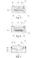
- FIGS. 3 to 7 illustrate various embodiments adapted to the recovery of pressure forces by a capsule as disclosed for example in the EP 2 520 333 A1 (Sorin CRM).
- this example is not limiting of the invention, which will be seen later that it applies both energy recovery systems using a seismic mass.
- the capsule is made, as illustrated Figures 3 and 4 , with a body 40 provided with one or more deformable elements 42 biased at the rate of changes in the pressure of the fluid in which the capsule is bathed, typically blood pressure variations.
- the deformable element 42 comprises a rigid surface 44 on which the pressure variations are exerted, and which is connected to the remainder of the body 40 by a deformable bellows 46.
- a deformable bellows 46 In the example of FIG.
- this surface / bellows assembly 44 / 46 is disposed on an axial end face of the capsule 40, while in the example of the Figure 4 there are two surface / bellows assemblies 44/46 disposed on lateral faces of the body 40 of the capsule, the rigid surfaces 44 being parallel to each other and to the main axis of the capsule.
- FIGS. 5 to 7 illustrate various possible structures of electrostatic transducer for the recovery of the energy of the pressure variations by the deformable element 42.
- This mode of transduction is however not limiting of the present invention which, as will be seen later, can also implement a transducer operating according to another principle, for example electromagnetic or piezoelectric.
- the movable surface 44 is coupled to the body 40 by an elastic connecting element 48 ( Figures 5 and 6 ) or a bellows 46 (Figure 7).
- This movable surface 44 is connected to a series of first conversion electrodes 50 via a coupling element 52.
- These electrodes are advantageously configured in the form of combs, made for example by conventional photoengraving techniques.
- the device also comprises second conversion electrodes 54 made in the form of interdigitating cross-combs with the combs of the electrodes 50 and connected to the body 40 by a peripheral support 56. The assembly formed by these electrodes 50, 54 is enclosed in the sealed volume 58 constituted by the body 40 enclosed by the deformable element 42.
- each cardiac cycle can thus recover a quantity of energy that will eventually be sufficient to ensure a permanent operation of the electronic circuits of the capsule, without additional energy input.
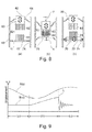
- the Figure 8 illustrates this conversion principle according to the invention.
- this structure comprises two moving parts, hereinafter referred to as “primary oscillating structure” (designated 60 in the figures) and “secondary oscillating structure” (designated 70 in the figures, these numerical references being retained in all the figures to designate, in different embodiments, functionally similar structures).
- the primary structure 60 is subjected to a low frequency external stress such as a direct force or, as in the embodiment of the Figure 8 , to the vibrations of a seismic mass 62 mounted on an elastic suspension 64 connected to the body 40 of the capsule.
- a low frequency external stress such as a direct force or, as in the embodiment of the Figure 8 .
- the secondary structure 70 in turn, comprises a movable element 72 and an elastically deformable element 74, which is in the embodiment of the invention.
- Figure 8 a suspension connecting the movable portion 70 to the body 40 of the capsule.
- the mass of the movable portion 72 and the elasticity of the suspension 74 define for the secondary structure 70 a specific resonance frequency, which typically is a frequency significantly higher than the frequency at which the primary structure 60 is biased.
- the two oscillating structures 60, 70 are coupled together by an electrostatic structure referenced 80, consisting of two respective series of electrodes 82, 84 whose mutual displacement has the effect of varying the capacitance of the capacitor constituted by these respective electrodes.
- an electrostatic structure referenced 80 consisting of two respective series of electrodes 82, 84 whose mutual displacement has the effect of varying the capacitance of the capacitor constituted by these respective electrodes.
- the electrodes 82 are integral with the primary oscillating structure 60, and the electrodes 84 are integral with the secondary oscillating structure 70.
- the primary structure 60 during its displacement (at the frequency of the cyclic external stress, corresponding to the curve A of FIG. 9) will be found opposite the secondary structure 7 with progressive interlocking of the electrodes 82, 84 (passage of state (a) in state (b) of the Figure 8 ).
- an electrostatic interaction typically an attraction, takes place between these electrodes. This interaction will have the effect of attracting the secondary structure 70 to the primary structure 60, as illustrated by the curve B of the Figure 9 , which represents the displacement of the structure 70: the attraction resulting from the electrostatic interaction corresponds to the displacement in the region (b) of the Figure 9 .
- the secondary structure 70 is the one that provides the transduction, these vibrations will lead to numerous transduction cycles before the primary structure returns to the zone of action of the secondary structure, to perform a new cycle-to-cycle of pulling. release.
- h a characteristic dimension of the fingers, such as their thickness, then to have a displacement x of the same order of magnitude as h, a stiffness k must be at least of the same order of magnitude as ⁇ * L * V 2 / ( g * h ).
- the deformable element must not be too flexible, that is to say with k too weak, because otherwise there will never be “let go”, the stiffness is never important enough to make out the structure of electrostatic attraction and produce relaxation around the equilibrium position.
- stiffness k of the system must be equal (to an order of magnitude) to ⁇ * L * V 2 / ( g * h ).
- the fingers must be sized such that the value of ⁇ * V 2 / g is equal to that of E * x * h 3 * w / L 4 , at one order of size.
- the fingers preferably have a width w greater than their thickness h , to make them rigid in the plane, compared to their desired out-of-plane flexibility.
- the multiplication of the operating frequency of the transducer (at the resonant natural frequency of the secondary oscillating structure 70 and not at the low frequency of the cyclic external stresses) has the effect of significantly increasing the conversion efficiency of the transformers transforming the energy. mechanical forces applied to the capsule in electrical energy. Indeed, if at each transduction cycle the transducer converts a given fraction of the mechanical energy into electrical energy, and if the transduction frequency is a multiple of the excitation frequency, then the transduction efficiency per excitation cycle is multiplied by the same amount.
- the deformable elastic element which defines the resonant frequency of the secondary structure 70 is no longer, as in the Figure 8 a suspension coupling this structure to the body of the capsule, but a spring 76 connecting the seismic mass 62 of the primary structure 60 to the movable portion 72 of the secondary structure 70.
- the electrodes 84 are still carried by the movable portion 72 of the secondary structure 70, however the electrodes 82 are fixed electrodes integral with the body 40 of the capsule.
- the system combining the primary structure 60 and the secondary structure 70 initially has a uniform motion induced by the low frequency excitation of the primary structure 60 by the external bias.
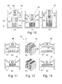
- this structure enters the field electrostatic attraction of the fixed structure constituted by the electrodes 82, as illustrated in step (b) of FIG. Figure 10 , then the secondary structure 70 will undergo, in addition to its restoring force the bonding to the primary structure 60 (due to the spring 76), an electrostatic attraction force which will cause a dissociation of the movement of the two primary structures 60 and secondary 70 ("pull" stage).
- the Figures 11, 12 and 13 illustrate three possible examples of electrostatic structure, where the configuration of the facing surfaces advantageously comprises large areas separated by a small gap, so as to create a high capacity and therefore a large variation in this capacity during the relative displacement of the electrodes. It is thus possible to provide in particular interdigitated combs for maximizing the surfaces opposite, with a variable overlap, out of plane ( Figure 11 ) or in the plan ( Figure 12 ).
- the capacitance variation can also result from a gap variation between the surfaces facing the electrodes ( Figure 13 ).
- the electrical energy transduction of the movement of the secondary structure 70 can be operated in various ways, schematically illustrated. Figures 14 to 16 .
- the Figure 14 illustrates the case of a piezoelectric transducer, for example by providing to partially realize the suspension of the secondary structure 70 carrying the electrodes 84 with a piezoelectric material 92, which will undergo stresses during the displacement and will therefore generate loads on these electrodes.
- These electrodes are located on either side of the piezoelectric material 92 and are connected to an electronic management circuit, typically a current rectifier and a filter capacitor.
- the Figure 15 illustrates the case of an electrostatic transducer, which in the illustrated embodiment comprises electrodes 50, 54 (functionally comparable to those described above with respect to Figures 5 to 7 ) forming a capacitor 94 whose capacity varies at high frequency.
- the terminals of this capacitor 94 are connected to an electronic circuit performing a charge and a discharge of the capacitor at each capacity variation cycle, so as to generate a positive electrical energy.
- a transducer 94 comprising a set of electrodes 50, 54 distinct from the electrodes 82, 84 of the electrostatic structure 80 carrying out the frequency conversion according to the invention has been described.
- the Figure 16 illustrates the case of an electromagnetic transducer, in which the mobile part of the secondary structure 70 supports a permanent magnet 96 movable in a fixed coil 98 integral with the body 40 (or vice versa) so as to generate a high frequency variable magnetic field .
- transducers are not limiting, and other techniques can also be used, for example based on magnetostrictive transducers, using electroactive polymers, etc.
- the Figure 17 illustrates another possible embodiment of the frequency conversion system according to the invention, implementing a rotation of the electrodes 84 relative to the electrodes 82, fixed and rigid.
- the states (a) to (d) illustrate the successive phases of deformation and relative displacements of the various elements of the assembly: at rest (state (a)), the combs and counter-combs of the respective electrodes 82, 84 are immobile and face to face.
- the central element 60 of the assembly constitutes the primary structure, which is subjected to external forces, via a seismic mass in the case of an inertial recovery, or a movable surface with a bellows in the case of a recovery. variations in pressure, and its movement is dictated by this cyclic external stress at low frequency.
- combs 84 will then enter a phase of free vibration at high frequency, this frequency which can reach several hundreds or even thousands of hertz being defined by the mass, very low combs 84 and the stiffness of the flexible element 76. of this vibration, the capacitance between the combs 84 and the counter-combs 82 will also vary at high frequency, and many charging / discharging cycles of the capacitor will be able to be performed, greatly increasing the extracted energy per unit of time.
- the Figure 18 illustrates the variations over time of the capacitance of the capacitor constituted by the combs and against-combs 82 and 84 of the whole of the Figure 17 .
- the Figure 19 illustrates the energy recovered at the output thanks to this variation of capacity.
- the capacitance variation comprises a sinusoid of decreasing amplitude O superimposed on high frequency variations V. Thanks to the frequency conversion phenomenon, the variable capacitor will present a very large number of maxima and minima per unit of time which, for the same solicitation cycle, will allow, as we can see on the Figure 19 , to recover an electrical energy E 2 much higher than that E 1 which would have been obtained with a conventional device without frequency conversion.
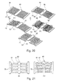
- the Figure 20 describes an alternative embodiment in which the electrostatic fingers 82, 84 of the electrostatic structure 80 constitute the element deformable elastic defining the own resonance frequency of the secondary oscillating structure 70.
- the fingers 82, 84 of the combs and against-combs have a geometry such that electrostatic instability phenomena at these fingers occur during the displacement of the moving part, thus creating high frequency capacitance variations.
- the fingers have a high aspect ratio, with an elongated and shallow shape, resulting in a high off-plane flexibility enabling the vertical electrostatic forces to be significant.
- the fingers 84 of the combs will bend so as to remain opposite the fingers 82 of the counter-combs, the electrostatic attraction force comb / counter-comb being strong in view of the mechanical rigidity of the combs.
- the stiffness of the combs takes over and the combs are released spontaneously from their electrostatic attraction vis-à-vis against-combs. If we superimpose several layers of comb / counter-comb as illustrated Figure 20 when the combs are freed from the attraction of the counter-combs of the initial layer, they will enter the field of attraction of the counter-combs of the upper layer. This jump from one layer to another will cause a high frequency vibration of the combs, causing a variation in the capacity of the transducer at this same frequency and thus increasing the number of charging and discharging cycles of the capacitor, and ultimately increasing. recovered energy.
Landscapes
- Health & Medical Sciences (AREA)
- Engineering & Computer Science (AREA)
- Life Sciences & Earth Sciences (AREA)
- General Health & Medical Sciences (AREA)
- Biomedical Technology (AREA)
- Nuclear Medicine, Radiotherapy & Molecular Imaging (AREA)
- Radiology & Medical Imaging (AREA)
- Animal Behavior & Ethology (AREA)
- Public Health (AREA)
- Veterinary Medicine (AREA)
- Molecular Biology (AREA)
- Power Engineering (AREA)
- Cardiology (AREA)
- Heart & Thoracic Surgery (AREA)
- Micromachines (AREA)
- Prostheses (AREA)
Abstract
Le module de récupération d'énergie de la capsule comprend : une structure oscillante primaire (60) soumise à une sollicitation cyclique extérieure à basse fréquence ; une structure oscillante secondaire (70) comprenant un élément élastique (74) et apte à vibrer librement en résonance à haute fréquence ; et une structure électrostatique (80) avec une première électrode (82) couplée à la structure primaire (60) et une seconde électrode (84) couplée à la structure secondaire (70). Les électrodes exercent entre elles une attraction mutuelle entrainant la structure secondaire en éloignement de sa position d'équilibre stable avec mise en tension de l'élément élastique, jusqu'à une limite au-delà de laquelle la structure secondaire est libérée par effet de relaxation pour vibrer librement à sa fréquence de résonance propre. Un transducteur couplé à la structure secondaire convertit en énergie électrique ces mouvements de vibration à haute fréquence.The energy recovery module of the capsule comprises: a primary oscillating structure (60) subjected to a low frequency external cyclic stress; a secondary oscillating structure (70) comprising an elastic element (74) and able to vibrate freely in high frequency resonance; and an electrostatic structure (80) with a first electrode (82) coupled to the primary structure (60) and a second electrode (84) coupled to the secondary structure (70). The electrodes exert a mutual attraction between them causing the secondary structure to move away from its stable equilibrium position with tensioning of the elastic element, to a limit beyond which the secondary structure is released by a relaxation effect. to vibrate freely at its own resonant frequency. A transducer coupled to the secondary structure converts these high frequency vibration motions into electrical energy.
Description
L'invention concerne, de façon générale, le domaine des "dispositifs médicaux actifs" tels que définis par la directive 93/42/CE du 14 juin 1993 du Conseil des communautés européennes, et notamment les "dispositifs médicaux implantables actifs" tels que définis par la directive du Conseil 90/385/CEE du 20 juin 1990.The invention relates generally to the field of "active medical devices" as defined by the Council of European Communities Directive 93/42 / EC of 14 June 1993, and in particular "active implantable medical devices" as defined by Council Directive 90/385 / EEC of 20 June 1990.
Cette définition inclut en particulier les appareils chargés de surveiller l'activité cardiaque et de générer des impulsions de stimulation, de resynchronisation, de défibrillation et/ou de cardioversion en cas de trouble du rythme détecté par l'appareil. Elle inclut aussi les appareils neurologiques, les implants cochléaires, etc., ainsi que les dispositifs de mesure de pH ou encore d'impédance intracorporelle (telle que mesure d'impédance transpulmonaire ou d'impédance intracardiaque).This definition includes in particular the devices responsible for monitoring cardiac activity and generating pacing, resynchronization, defibrillation and / or cardioversion pulses in the event of arrhythmia detected by the device. It also includes neurological devices, cochlear implants, etc., as well as devices for measuring pH or intracorporeal impedance (such as measurement of transpulmonary impedance or intracardiac impedance).
L'invention concerne plus particulièrement ceux de ces dispositifs qui mettent en oeuvre des capsules autonomes implantées et dépourvues de toute liaison physique à un dispositif principal implanté (tel qu'un boitier de générateur d'impulsions de stimulation).The invention relates more particularly to those devices that implement implanted autonomous capsules and devoid of any physical connection to an implanted main device (such as a stimulation pulse generator box).
Ces capsules autonomes sont dénommées pour cette raison "capsules leadless", pour les distinguer des électrodes ou des capteurs disposés à l'extrémité distale d'une sonde (lead), cette sonde étant parcourue sur toute sa longueur par un ou plusieurs conducteurs reliant par voie galvanique l'électrode ou le capteur à un générateur connecté à l'extrémité opposée, proximale, de la sonde.These autonomous capsules are named for this reason " leadless capsules", to distinguish them from the electrodes or sensors arranged at the distal end of a probe (lead), this probe being traversed along its length by one or more connecting conductors by Galvanically route the electrode or sensor to a generator connected to the opposite, proximal end of the probe.
De telles capsules leadless sont par exemple décrites dans les
Ces capsules leadless peuvent être par exemple des capsules épicardiques, fixées à la paroi extérieure du coeur, ou bien des capsules endocavitaires, fixées à la paroi intérieure d'une cavité ventriculaire ou auriculaire au moyen d'une vis d'ancrage saillante, prolongeant axialement le corps de la capsule et destinée à pénétrer dans le tissu cardiaque par vissage au site d'implantation. L'invention n'est toutefois pas limitée à un type particulier de capsule, et elle est applicable indifféremment à tout type de capsule leadless, quelle que soit sa destination fonctionnelle.These leadless capsules may for example be epicardial capsules, attached to the outer wall of the heart, or endocardial capsules, attached to the inner wall of a ventricular or atrial cavity by means of a projecting anchoring screw, extending axially. the body of the capsule and intended to penetrate into the heart tissue by screwing to the implantation site. The invention is however not limited to a particular type of capsule, and it is applicable regardless of any type of leadless capsule , regardless of its functional purpose.
Une capsule leadless comprend divers circuits électroniques, capteurs, etc. ainsi que des moyens émetteurs/récepteurs de communication sans fil pour l'échange de données à distance.A leadless capsule includes various electronic circuits, sensors, etc. as well as wireless communication transmitter / receiver means for remote data exchange.
Dans tous les cas, le traitement des signaux au sein de la capsule et leur transmission à distance nécessite une énergie non négligeable par rapport aux ressources énergétiques que peut stocker cette capsule. Or, compte tenu de son caractère autonome, la capsule ne peut faire appel qu'à ses ressources propres, à savoir un système d'auto-alimentation intégré comprenant un récupérateur d'énergie associé à une petite batterie tampon intégrée.In all cases, the processing of signals within the capsule and their remote transmission requires a significant energy compared to the energy resources that can store this capsule. However, given its autonomous nature, the capsule can only appeal to its own resources, namely an integrated self-power system comprising a power recovery associated with a small integrated buffer battery.
Un premier type de récupérateur d'énergie utilise un transducteur couplé à un mécanisme inertiel comportant une masse mobile, dite "masse sismique", oscillant dans la capsule au gré des déplacements de cette dernière, qui est soumise aux efforts dus aux mouvements de la paroi de l'organe du patient et aux forces fluidiques du milieu environnant. La puissance récupérée dépend principalement de la fréquence d'excitation de la masse sismique, de l'amplitude de ce mouvement et de la valeur de masse. Or, dans le cas de l'environnement du corps humain, les excitations provenant de l'accélération du corps ou des organes n'ont pas de fréquences spécifiques stables pour lesquelles la récupération pourrait être optimisée de manière à produire une résonance du mécanisme. De la sorte, il n'est pas possible de bénéficier d'une amplification mécanique qui accroitrait l'amplitude et permettrait de récupérer un maximum de l'énergie inertielle. De plus, les fréquences d'excitation en jeu sont très basses, de l'ordre de 0,5 à 10 Hz pour les fréquences typiques de pulsation du flux sanguin et de 15 à 40 Hz pour les mouvements des parois cardiaques, ce qui limite les performances du récupérateur. Enfin, la valeur de masse de la masse sismique doit rester très faible, pour des raisons de respect de la miniaturisation.A first type of energy recuperator uses a transducer coupled to an inertial mechanism comprising a moving mass, called "seismic mass", oscillating in the capsule at the discretion of the latter, which is subjected to the forces due to the movements of the wall of the patient's organ and the fluidic forces of the surrounding medium. The recovered power depends mainly on the excitation frequency of the seismic mass, the amplitude of this movement and the mass value. However, in the case of the human body environment, the excitations resulting from the acceleration of the body or organs do not have stable specific frequencies for which the recovery could be optimized so as to produce a resonance of the mechanism. In this way, it is not possible to benefit from a mechanical amplification that increases the amplitude and would recover a maximum of the inertial energy. In addition, the excitation frequencies in play are very low, of the order of 0.5 to 10 Hz for the typical frequencies of blood flow pulsation and 15 to 40 Hz for the movements of the heart walls, which limits the performance of the recuperator. Finally, the mass value of the seismic mass must remain very low, for reasons of respect for miniaturization.
Un autre type de récupérateur d'énergie, non inertiel, utilise les variations de pression du fluide environnant la capsule (typiquement le milieu sanguin) pour déformer ou déplacer cycliquement une membrane flexible ou un soufflet couplé à un transducteur. L'énergie susceptible d'être récupérée dépend principalement de l'amplitude du mouvement cyclique, de la membrane ou du soufflet actionné par le fluide environnant (amplitude qui est nécessairement limitée pour des raisons de fiabilité mécanique), de la fréquence de ce mouvement cyclique et de l'aire de la surface mobile (nécessairement réduite pour des raisons évidentes de miniaturisation de la capsule). Ici encore, les variations de pression se situent à la fréquence cardiaque, de l'ordre de 1 à 3 Hz, et ne permettent donc de solliciter le transducteur qu'à basse fréquence, imposant de fait une limitation des performances du récupérateur d'énergie.Another type of non-inertial energy recuperator uses pressure variations of the fluid surrounding the capsule (typically the blood medium) to deform or cyclically displace a flexible membrane or bellows coupled to a transducer. The energy that can be recovered depends mainly on the amplitude of the cyclic movement, the membrane or the bellows actuated by the surrounding fluid (amplitude that is necessarily limited for reasons of mechanical reliability), the frequency of this cyclic movement and the area of the moving surface (necessarily reduced for obvious reasons of miniaturization of the capsule). Here again, the pressure variations are at the heart rate, of the order of 1 to 3 Hz, and therefore allow to solicit the transducer at low frequency, imposing in fact a limitation of the performance of the energy recuperator .
Le but de l'invention est de pallier ces limitations en proposant un nouveau type de récupérateur d'énergie pourvu d'un mécanisme permettant d'accroitre la fréquence d'excitation du transducteur, de manière à bénéficier, pour un seul cycle de sollicitation externe, d'une pluralité de cycles de transduction pour la conversion de l'énergie mécanique procurée.The object of the invention is to overcome these limitations by proposing a new type of energy recuperator provided with a mechanism for increasing the excitation frequency of the transducer, so as to benefit for a single external solicitation cycle of a plurality of transduction cycles for converting the provided mechanical energy.
Sur cet aspect, le
Un autre but de l'invention est de proposer un tel mécanisme qui puisse être utilisé aussi bien avec un récupérateur inertiel à masse sismique, sollicité par les vibrations et mouvements externes du milieu environnant, qu'avec un récupérateur non inertiel de type à membrane ou à soufflet, sollicité par les variations cycliques de pression du fluide dans lequel baigne la capsule.Another object of the invention is to propose such a mechanism that can be used both with an inertial recuperator with seismic mass, solicited by the vibrations and external movements of the surrounding medium, with a non-inertial recuperator of membrane type or bellows, biased by the cyclic pressure variations of the fluid in which bathes the capsule.
Un autre but encore de l'invention est de proposer un tel mécanisme qui ne mette en oeuvre ni élément magnétique qui créerait un risque lors d'un examen IRM, ni choc ou contact mécanique répétitif qui entrainerait sur le long terme des problèmes de fiabilité mécanique.Yet another object of the invention is to propose such a mechanism which does not implement any magnetic element which would create a risk during an MRI examination, nor a shock or a repetitive mechanical contact which would lead in the long term to mechanical reliability problems. .
L'idée de base de l'invention consiste à mettre en oeuvre deux éléments mobiles, à savoir :
- une première structure, ci-après "structure oscillante primaire" soumise à une sollicitation extérieure à basse fréquence qui peut être une force directement appliquée par exemple à partir des variations de pression déplaçant cycliquement une membrane ou un soufflet, ou bien indirectement par une masse sismique solidaire de cette structure, cette structure se déplaçant à cette même fréquence basse ; et
- une deuxième structure, ci-après "structure oscillante secondaire" vibrant à plus haute fréquence, typiquement avec un effet de résonance et couplée au transducteur du récupérateur d'énergie.
- a first structure, hereinafter referred to as a "primary oscillating structure" subjected to a low frequency external stress which may be a force directly applied for example from pressure variations cyclically displacing a membrane or a bellows, or indirectly by a seismic mass integral with this structure, this structure moving at this same low frequency; and
- a second structure, hereinafter "oscillating secondary structure" vibrating at a higher frequency, typically with a resonance effect and coupled to the transducer of the energy recuperator.
Pour réaliser cette conversion de fréquence, les deux structures primaire et secondaire sont couplées entre elles par un mécanisme réalisant une fonction de "tirer-lâcher" créant un phénomène de relaxation.To achieve this frequency conversion, the two primary and secondary structures are coupled together by a mechanism performing a "pull-release" function creating a relaxation phenomenon.
Ce couplage entre les deux structures oscillantes est réalisé, de façon caractéristique, par une structure de couplage opérant par interaction électrostatique, donc sans élément magnétique ni élément mécanique frottant ou à impact.This coupling between the two oscillating structures is realized, typically, by a coupling structure operating by electrostatic interaction, therefore without magnetic element or mechanical element rubbing or impact.
Plus précisément, l'invention propose une capsule intracorporelle autonome comportant, de manière en elle-même connue, un corps et, à l'intérieur de ce corps, des circuits électroniques et un module de récupération d'énergie pour l'alimentation électrique de ces circuits électroniques. Le module de récupération d'énergie comprend un transducteur apte à convertir en énergie électrique une sollicitation physique extérieure cyclique appliquée au corps de la capsule et résultant de variations de pression dans le milieu environnant la capsule et/ou de mouvements d'une paroi à laquelle est ancrée la capsule.More specifically, the invention proposes an autonomous intracorporeal capsule comprising, in a manner known per se, a body and, inside this body, electronic circuits and an energy recovery module for the power supply of the body. these electronic circuits. The energy recovery module comprises a transducer able to convert into electrical energy a cyclic external physical stress applied to the body of the capsule and resulting from pressure variations in the medium surrounding the capsule and / or movements of a wall to which is anchored the capsule.
De façon caractéristique de l'invention, le module de récupération d'énergie comprend :
- une structure oscillante primaire soumise à la sollicitation cyclique extérieure, cette structure oscillante primaire étant apte à être déplacée alternativement dans un sens et dans l'autre à la fréquence de la sollicitation cyclique extérieure ;
- une structure oscillante secondaire non soumise à la sollicitation extérieure cyclique, cette structure oscillante secondaire comprenant un élément élastique déformable et étant apte à vibrer librement à une fréquence de résonance propre supérieure à la fréquence de la sollicitation cyclique extérieure ; et
- une structure électrostatique comprenant une première électrode de condensateur couplée à la structure oscillante primaire ou au corps de la capsule, et une seconde électrode de condensateur couplée à la structure oscillante secondaire.
- a primary oscillating structure subjected to external cyclic loading, this primary oscillating structure being able to be displaced alternately in one direction and the other at the frequency of external cyclic stress;
- a secondary oscillating structure not subject to cyclic external stress, this secondary oscillating structure comprising a elastic element deformable and being able to vibrate freely at a natural resonance frequency greater than the frequency of external cyclic stress; and
- an electrostatic structure comprising a first capacitor electrode coupled to the primary oscillating structure or the body of the capsule, and a second capacitor electrode coupled to the secondary oscillating structure.
La première et la seconde électrode sont configurées entre elles de manière que, sous l'effet de la sollicitation cyclique extérieure appliquée à la structure oscillante primaire, elles exercent entre elles sous l'effet d'interactions électrostatiques une force d'attraction mutuelle entrainant la structure oscillante secondaire en éloignement de sa position d'équilibre stable et avec mise en tension de l'élément élastique déformable. La structure oscillante secondaire est ainsi entrainée jusqu'à une limite où la tension exercée par l'élément élastique déformable dépasse la force d'attraction mutuelle des électrodes, limite au-delà de laquelle la structure oscillante secondaire est libérée par effet de relaxation pour vibrer librement à ladite fréquence de résonance propre. Enfin, le transducteur est couplé à la structure oscillante secondaire, pour convertir en énergie électrique les mouvements de vibration de celle-ci à ladite fréquence de résonance propre.The first and second electrodes are configured together so that, under the effect of external cyclic stress applied to the primary oscillating structure, they exert between each other, under the effect of electrostatic interactions, a force of mutual attraction resulting in the secondary oscillating structure away from its stable equilibrium position and with tensioning of the deformable elastic element. The secondary oscillating structure is thus driven to a limit where the tension exerted by the deformable elastic element exceeds the mutual attraction force of the electrodes, which limit beyond which the secondary oscillating structure is released by a relaxation effect to vibrate. freely at said own resonance frequency. Finally, the transducer is coupled to the secondary oscillating structure, for converting the vibrational motions thereof to electrical energy at said resonance frequency into electrical energy.
Le transducteur peut être de type électrostatique. Il comprend alors des électrodes de conversion formant un condensateur, l'une de ces électrodes de conversion étant entrainée cycliquement par la structure oscillante secondaire, et le transducteur opérant par modification cyclique des surfaces en vis-à-vis et/ou de l'intervalle diélectrique des électrodes de conversion avec variation corrélative de la capacité du condensateur. Les électrodes de conversion peuvent notamment inclure les première et seconde électrodes de la structure électrostatique.The transducer may be of the electrostatic type. It then comprises conversion electrodes forming a capacitor, one of these conversion electrodes being driven cyclically by the secondary oscillating structure, and the transducer operating by cyclic modification of the surfaces facing each other and / or the gap. dielectric conversion electrodes with correlative variation of the capacity of the capacitor. The conversion electrodes may in particular include the first and second electrodes of the electrostatic structure.
Le transducteur peut également être de type piézoélectrique, comprenant un élément piézoélectrique déformable configuré pour être contraint cycliquement par la structure oscillante secondaire.The transducer may also be of the piezoelectric type, comprising a deformable piezoelectric element configured to be cyclically constrained by the secondary oscillating structure.
Le transducteur peut encore être de type électromagnétique, comprenant un élément magnétique mobile ou un bobinage mobile configuré pour être entrainé cycliquement par la structure oscillante secondaire.The transducer may also be of the electromagnetic type, comprising a movable magnetic element or a mobile coil configured to be driven cyclically by the secondary oscillating structure.
Dans un premier mode de réalisation, la structure oscillante primaire comprend une masse inertielle couplée au corps de la capsule par une suspension élastique apte à être sollicitée cycliquement sous l'effet des mouvements de la capsule dans le milieu environnant. La structure oscillante primaire peut notamment être couplée à une surface déformable extérieure au corps de la capsule, apte à être sollicitée cycliquement sous l'effet des variations de pression dans le milieu environnant la capsule.In a first embodiment, the primary oscillating structure comprises an inertial mass coupled to the body of the capsule by an elastic suspension able to be cyclically stressed by the movement of the capsule in the surrounding environment. The primary oscillating structure may in particular be coupled to a deformable surface outside the body of the capsule, able to be cyclically stressed under the effect of pressure variations in the medium surrounding the capsule.
Dans un second mode de réalisation, la structure oscillante primaire et la structure oscillante secondaire sont couplées entre elles par la structure électrostatique. La structure oscillante secondaire peut notamment être couplée au corps de la capsule par l'élément élastique déformable, et la première électrode de la structure électrostatique peut être reliée à la structure oscillante primaire, la seconde électrode de la structure électrostatique étant reliée à la structure oscillante secondaire.In a second embodiment, the primary oscillating structure and the secondary oscillating structure are coupled together by the electrostatic structure. The secondary oscillating structure can in particular be coupled to the body of the capsule by the deformable elastic element, and the first electrode of the electrostatic structure can be connected to the primary oscillating structure, the second electrode of the electrostatic structure being connected to the oscillating structure secondary.
Dans un troisième mode de réalisation, la structure oscillante primaire et la structure oscillante secondaire sont couplées entre elles par l'élément élastique déformable. La première électrode de la structure électrostatique peut être reliée au corps de la capsule, la seconde électrode de la structure électrostatique étant reliée à la structure oscillante secondaire.In a third embodiment, the primary oscillating structure and the secondary oscillating structure are coupled together by the deformable elastic element. The first electrode of the electrostatic structure can be connected to the body of the capsule, the second electrode of the electrostatic structure being connected to the secondary oscillating structure.
Dans un quatrième mode de réalisation, les première et seconde électrodes de la structure électrostatique sont réalisées sous forme de doigts respectifs de peigne(s) et contre-peigne(s) imbriqués. Les doigts de l'une au moins des première et seconde électrodes de la structure électrostatique sont alors des doigts élastiquement déformables, formant ensemble l'élément élastique déformable de la structure oscillante secondaire. Les extrémités distales de ces doigts peuvent être réunies entre elles par un couplage rigide.In a fourth embodiment, the first and second electrodes of the electrostatic structure are formed as respective fingers of comb (s) and counter-comb (s) imbricated. The fingers of at least one of the first and second electrodes of the electrostatic structure are then elastically deformable fingers, forming together the deformable elastic element of the secondary oscillating structure. The distal ends of these fingers can be joined together by a rigid coupling.
On va maintenant décrire un exemple de mise en oeuvre du dispositif de l'invention, en référence aux dessins annexés où les mêmes références numériques désignent d'une figure à l'autre des éléments identiques ou fonctionnellement semblables.
- La
Figure 1 illustre de façon schématique un ensemble de dispositifs médicaux comprenant notamment des capsules leadless, implantées au sein du corps d'un patient. - La
Figure 2 est un schéma par blocs fonctionnels montrant les différents étages constitutifs d'une capsule leadless. - Les
Figures 3 et 4 illustrent deux formes de réalisation possibles du corps d'une capsule leadless à récupération des variations de pression du fluide environnant. - Les
Figures 5 à 7 illustrent diverses variantes de la structure interne d'une capsule leadless connue à récupération des variations de pression et transducteur électrostatique. - La
Figure 8 illustre le principe de conversion de fréquence selon l'invention, mettant en oeuvre une double structure oscillante et un couplage électrostatique à relaxation. - La
Figure 9 illustre les déplacements respectifs des deux structures oscillantes de la configuration de laFigure 8 , au cours d'un cycle de sollicitation mécanique de la structure primaire. - La
Figure 10 est homologue de laFigure 8 , pour une variante de réalisation avec un jeu d'électrodes fixes solidaires du corps de la capsule. - Les
Figures 11 à 13 illustrent divers exemples possibles de configuration électrostatique entre les deux structures oscillantes. - Les
Figures 14 à 16 illustrent divers exemples possibles de transducteurs qu'il est possible d'associer à la structure oscillante secondaire du mécanisme de l'invention. - La
Figure 17 illustre une implémentation possible du système de conversion de fréquence selon l'invention, utilisant la rotation de doigts électrostatiques rigides par rapport à une structure centrale formant la structure oscillante primaire. - La
Figure 18 est une courbe montrant les variations de capacité au cours du temps d'une structure telle que celle de laFigure 17 . - La
Figure 19 est une courbe montrant les variations de l'énergie générée en sortie au moyen de la structure de laFigure 17 , et en comparaison l'énergie générée par un dispositif récupérateur conventionnel. - La
Figure 20 illustre une autre implémentation possible du système de conversion de fréquence selon l'invention, utilisant la déformation de doigts électrostatiques flexibles sous l'effet de forces d'attraction électrostatique. - La
Figure 21 illustre une variante du système de laFigure 20 , dans laquelle les extrémités des doigts flexibles sont reliées ensemble afin de s'assurer de la synchronisation de leurs mouvements à haute fréquence.
- The
Figure 1 schematically illustrates a set of medical devices including leadless capsules , implanted within the body of a patient. - The
Figure 2 is a functional block diagram showing the different constituent stages of a leadless capsule . - The
Figures 3 and 4 illustrate two possible embodiments of the body of a leadless capsule to recover pressure variations of the surrounding fluid. - The
Figures 5 to 7 illustrate various variants of the internal structure of a known leadless capsule with pressure change recovery and electrostatic transducer. - The
Figure 8 illustrates the principle of frequency conversion according to the invention, implementing a double oscillating structure and a relaxation electrostatic coupling. - The
Figure 9 illustrates the respective displacements of the two oscillating structures of the configuration of theFigure 8 , during a mechanical stress cycle of the primary structure. - The
Figure 10 is counterpart of theFigure 8 , for an alternative embodiment with a set of fixed electrodes integral with the body of the capsule. - The
Figures 11 to 13 illustrate various possible examples of electrostatic configuration between the two oscillating structures. - The
Figures 14 to 16 illustrate various possible examples of transducers that can be associated with the secondary oscillating structure of the mechanism of the invention. - The
Figure 17 illustrates a possible implementation of the frequency conversion system according to the invention, using the rotation of rigid electrostatic fingers with respect to a central structure forming the primary oscillating structure. - The
Figure 18 is a curve showing the variations of capacity over time of a structure such as that of theFigure 17 . - The
Figure 19 is a curve showing the variations of the energy generated at the output by means of the structure of theFigure 17 , and in comparison the energy generated by a conventional recuperative device. - The
Figure 20 illustrates another possible implementation of the frequency conversion system according to the invention, using the deformation of flexible electrostatic fingers under the effect of electrostatic attraction forces. - The
Figure 21 illustrates a variant of the system of theFigure 20 wherein the ends of the flexible fingers are connected together to ensure synchronization of their high frequency movements.
On va tout d'abord décrire, en référence aux
Sur la
Celui-ci est équipé par exemple d'un implant 10 tel qu'un défibrillateur/ stimulateur/resynchroniseur implanté, un défibrillateur sous-cutané ou encore un enregistreur longue durée. Ce dispositif 10 est le dispositif maitre d'un réseau comportant une pluralité de dispositifs esclaves 12 à 18, qui peuvent notamment inclure des capsules intracardiaques 12 ou épicardiques 14 implantées directement sur le coeur du patient, d'autres dispositifs 16 tels que capteurs de myopotentiels ou dispositifs de stimulation neurologique, et éventuellement un dispositif externe 18 disposé sur un brassard et pourvu d'électrodes en contact avec la peau. Le dispositif 10 peut également être utilisé en tant que passerelle avec le monde extérieur pour communiquer avec un périphérique externe 20 de type programmateur ou dispositif de télétransmission de données avec lequel il pourra communiquer par télémétrie.This is equipped for example with an
La
La capsule comporte par exemple un couple d'électrodes 22, 24 reliées à un circuit 26 générateur d'impulsions de stimulation (pour une capsule active incorporant cette fonction) et/ou à un circuit de détection 28 servant au recueil des potentiels de dépolarisation recueillis entre les électrodes 22 et 24. Un circuit central 30 inclut l'ensemble de l'électronique permettant de piloter les diverses fonctions de la capsule, la mémorisation des signaux recueillis, etc. Il comprend un microcontrôleur et un oscillateur générant les signaux d'horloge nécessaires au fonctionnement du microcontrôleur et à la communication. Il peut également contenir un convertisseur analogique/numérique et une mémoire de stockage numérique. La capsule peut également être pourvue d'un capteur 32 tel qu'un capteur d'accélération, de pression, un capteur hémodynamique, de température, de saturation en oxygène, etc. La capsule comprend un module de récupération d'énergie 34 alimentant l'ensemble des circuits via un étage de gestion d'énergie 36. Les électrodes 22 et 24 sont également reliées à un circuit d'émission/réception d'impulsions 38 servant à la communication sans fil avec le dispositif maitre ou les autres capsules.The capsule comprises, for example, a pair of
L'invention concerne plus particulièrement le module de récupération d'énergie 34.The invention relates more particularly to the
Il s'agit de récupérer l'énergie contenue dans des efforts mécaniques auxquels est soumise la capsule.It is a question of recovering the energy contained in mechanical forces to which the capsule is subjected.
Deux cas particuliers de sollicitations extérieures peuvent être envisagés :
- récupération de l'énergie vibratoire, également dénommée énergie inertielle, au moyen d'une masse sismique qui subit les efforts d'accélération et produit une force égale au produit de cette accélération par la masse en mouvement ; ou
- récupération des variations de pression cardiaque, en prévoyant qu'une partie du corps de la capsule soit déformable sous l'effet de ces variations de pression. La force produite est alors proportionnelle au produit de l'amplitude des variations de pression par la surface de l'élément déformable.
- recovery of vibratory energy, also called inertial energy, by means of a seismic mass which undergoes the acceleration forces and produces a force equal to the product of this acceleration by the moving mass; or
- recovering variations in cardiac pressure, by providing that a portion of the body of the capsule is deformable under the effect of these pressure variations. The force produced is then proportional to the product of the amplitude of the pressure variations by the surface of the deformable element.
Dans l'un ou l'autre cas, la fréquence des sollicitations cycliques se situe, dans le milieu cardiaque, dans des plages de l'ordre de 1 à 3 Hz (fréquence des battements cardiaques) et également autour de 15 à 20 Hz, pour les vibrations d'une masse sismique, et dans la plage 1 à 3 Hz des battements cardiaques pour les variations de la pression sanguine.In either case, the frequency of the cyclic stresses is, in the cardiac medium, in ranges of the order of 1 to 3 Hz (frequency of heart beats) and also around 15 to 20 Hz, for the vibrations of a seismic mass, and in the
Les
Pour prendre en compte les variations de pression, la capsule est réalisée, comme illustré
Les
Sur les
On dispose ainsi d'un transducteur qui peut être modélisé par un condensateur à capacité variable comprenant :
- une première électrode de conversion, suspendue, constituée par les peignes 50 qui sont mécaniquement et électriquement réunis entre eux et à la surface mobile via
l'élément 52 ; - une deuxième électrode de conversion, fixe, constituée par les contre-peignes 54 qui sont mécaniquement et électriquement réunis entre eux et au corps 40 via
le support 56 ; et - un intervalle diélectrique, défini entre les deux électrodes.
- a first suspended conversion electrode constituted by the
combs 50 which are mechanically and electrically joined to each other and to the moving surface via theelement 52; - a second fixed conversion electrode formed by the counter-combs 54 which are mechanically and electrically joined together and to the
body 40 via thesupport 56; and - a dielectric gap defined between the two electrodes.
Dans la configuration de la
Si le condensateur a été chargé au préalable, une diminution de sa capacité produira un surcroit d'énergie qui pourra être déchargé par des circuits appropriés vers un module de stockage, et vice versa. À chaque cycle cardiaque on pourra ainsi récupérer une quantité d'énergie qui sera à terme suffisante pour assurer un fonctionnement permanent des circuits électroniques de la capsule, sans apport supplémentaire d'énergie.If the capacitor has been charged beforehand, a decrease in its capacitance will produce additional energy that can be discharged by appropriate circuits to a storage module, and vice versa. Each cardiac cycle can thus recover a quantity of energy that will eventually be sufficient to ensure a permanent operation of the electronic circuits of the capsule, without additional energy input.
On va maintenant décrire, en référence aux
La
Essentiellement, il s'agit d'utiliser les forces électrostatiques mises en jeu lors de l'application d'une tension d'une charge électrique entre deux parties d'un condensateur à capacité variable afin de provoquer un phénomène de "tirer-lâcher" d'une structure de transduction d'énergie mécanique en énergie électrique.Essentially, it is to use the electrostatic forces involved when applying a voltage of an electric charge between two parts of a capacitor with variable capacity to cause a phenomenon of "pull-let go" a structure of mechanical energy transduction into electrical energy.
Concrètement, cette structure comprend deux parties mobiles, ci-après désignées "structure oscillante primaire" (désignée 60 sur les figures) et "structure oscillante secondaire" (désignée 70 sur les figures, ces références numériques étant conservées sur toutes les figures pour désigner, dans des modes de réalisation différents, des structures fonctionnellement semblables).Specifically, this structure comprises two moving parts, hereinafter referred to as "primary oscillating structure" (designated 60 in the figures) and "secondary oscillating structure" (designated 70 in the figures, these numerical references being retained in all the figures to designate, in different embodiments, functionally similar structures).
La structure primaire 60 est soumise à une sollicitation extérieure à basse fréquence telle qu'une force directe ou, comme dans le mode de réalisation de la
La structure secondaire 70, quant à elle, comprend un élément 72 mobile et un élément élastiquement déformable 74, qui est dans le mode de réalisation de la
La masse de la partie mobile 72 et l'élasticité de la suspension 74 définissent pour la structure secondaire 70 une fréquence de résonance propre, qui de façon caractéristique est une fréquence notablement plus élevée que la fréquence à laquelle est sollicitée la structure primaire 60.The mass of the
Les deux structures oscillantes 60, 70 sont couplées entre elles par une structure électrostatique référencée 80, constituée de deux séries respectives d'électrodes 82, 84 dont le déplacement mutuel a pour effet de faire varier la capacité du condensateur constitué par ces électrodes respectives. On exposera ci-après diverses configurations possibles de ces électrodes 82, 84 de la structure électrostatique 80, les mêmes références numériques 80, 82 et 84 étant conservées sur les différentes figures pour désigner des éléments fonctionnement semblables.The two
Dans le mode de réalisation de la
On va maintenant exposer le comportement dynamique de cette structure, en référence aux
La structure primaire 60, lors de son déplacement (à la fréquence de la sollicitation extérieure cyclique, correspondant à la courbe A de la Figure 9) va se retrouver en regard de la structure secondaire 7 avec imbrication progressive des électrodes 82, 84 (passage de l'état (a) à l'état (b) de la
Si l'on applique une tension ou une charge électrique entre les électrodes 82, 84 en regard, une interaction électrostatique, typiquement une attraction, a lieu entre ces électrodes. Cette interaction aura pour effet d'attirer la structure secondaire 70 vers la structure primaire 60, comme illustré par la courbe B de la
La force d'attraction électrostatique entre les deux structures 60 et 70 va passer par un maximum, suffisamment fort pour que la structure secondaire 70 soit entrainée par la structure primaire 60 (étape de "tirer"). Mais la course de la structure secondaire 70 étant plus limitée, une fois une limite L atteinte la rigidité de la suspension 74 va séparer les deux structures (étape de "lâcher").The electrostatic attraction force between the two
N'étant plus attirée par la structure primaire 60 qui s'éloigne, la structure secondaire 70, lâchée à partir d'un état étiré de la suspension 74, va entrer en vibration libre à sa fréquence de résonance propre, comme illustré en (c) sur les
La structure secondaire 70 étant celle qui assure la transduction, ces vibrations vont entrainer de nombreux cycles de transduction avant que la structure primaire ne revienne dans la zone d'action de la structure secondaire, pour effectuer un nouveau cycle-à-cycle de tirer-lâcher.Since the
Pour que l'effet recherché de "tirer-lâcher" soit significatif, il faut que l'attraction électrostatique engendre une déformation du même ordre de grandeur que les dimensions caractéristiques de la structure.For the desired effect of "pull-release" is significant, it is necessary that the electrostatic attraction generates a deformation of the same order of magnitude as the characteristic dimensions of the structure.
Ici et dans la suite, l'expression "du même ordre de grandeur" devra être comprise dans son acception spécifique conventionnellement employée en physique, c'est-à-dire "dans un rapport de 0,1 à 10".Here and in the following, the expression "of the same order of magnitude" will have to be understood in its specific meaning conventionally used in physics, that is to say "in a ratio of 0.1 to 10".
Plus concrètement, la force électrostatique d'attraction fe (exprimée en N) entre les doigts formant les électrodes est : 
L étant la longueur de la surface en regard des électrodes dans la dimension perpendiculaire au déplacement de couplage,
V étant la tension électrique appliquée entre les électrodes, et
g étant l'entrefer séparant ces électrodes.More concretely, the electrostatic attraction force f e (expressed in N) between the fingers forming the electrodes is:
Where L is the length of the surface facing the electrodes in the dimension perpendicular to the coupling displacement,
V is the voltage applied between the electrodes, and
g being the air gap separating these electrodes.
Si l'élément déformable soutenant la structure secondaire a une raideur k (en N/m), alors la force élastique de rappel fr sous une déformation x est (en N) : ![]()
![]()
Ainsi, sous équilibre quasi-statique lors du mouvement de tirer, le déplacement est : ![]()
![]()
Si l'on note h une dimension caractéristique des doigts, comme par exemple leur épaisseur, alors pour avoir un déplacement x du même ordre de grandeur que h, il faut une raideur k qui soit au moins du même ordre de grandeur que ε*L*V 2/(g*h).If we denote h a characteristic dimension of the fingers, such as their thickness, then to have a displacement x of the same order of magnitude as h, a stiffness k must be at least of the same order of magnitude as ε * L * V 2 / ( g * h ).
A contrario, l'élément déformable ne doit pas être trop souple, c'est-à-dire avec k trop faible, car sinon il n'y aura jamais de "lâcher", la raideur n'étant jamais assez importante pour faire sortir la structure de l'attraction électrostatique et produire la relaxation autour de la position d'équilibre. On the other hand, the deformable element must not be too flexible, that is to say with k too weak, because otherwise there will never be "let go", the stiffness is never important enough to make out the structure of electrostatic attraction and produce relaxation around the equilibrium position.
C'est pourquoi il faut que la raideur k du système soit égale (à un ordre de grandeur près) à ε*L*V 2/(g*h).This is why the stiffness k of the system must be equal (to an order of magnitude) to ε * L * V 2 / ( g * h ).
Du point de vue mécanique, si l'on assimile chaque doigt à une poutre de longueur L, d'épaisseur h (dans le sens de la direction de flexion) et de largeur w (perpendiculairement à la direction de flexion), on peut exprimer la valeur de la force électrostatique comme une force linéique (exprimée en N/m) de valeur fe = ε*V 2/g, s'exerçant le long des doigts.From the mechanical point of view, if we assimilate each finger to a beam of length L , of thickness h (in the direction of bending direction) and of width w (perpendicular to the direction of bending), we can express the value of the electrostatic force as a linear force (expressed in N / m) of value f e = ε * V 2 / g , exerted along the fingers.
En utilisant les lois de la mécanique, on peut exprimer la rigidité fr du doigt par unité de longueur (en N/m), lorsque ce dernier subit une flexion d'amplitude x en bout de doigt, par : ![]()
où E représente le module d'Young du matériau du doigt.Using the laws of mechanics, we can express the rigidity f r of the finger per unit length (in N / m), when the latter undergoes a flexion of amplitude x at the end of the finger, by: ![]()
where E represents the Young's modulus of the finger material.
Le phénomène de flexion des doigts, et donc de conversion de fréquence, devient significatif lorsque fe devient notablement supérieure à fr , pour une déflexion x de l'ordre de grandeur de h. The phenomenon of flexion of the fingers, and therefore of frequency conversion, becomes significant when f e becomes noticeably greater than f r , for a deflection x of the order of magnitude of h.
Ainsi, pour produire les effets caractéristiques de la présente invention, les doigts doivent être dimensionnés de telle manière que la valeur de ε*V 2/g soit égale à celle de E*x*h 3 *w/L 4, à un ordre de grandeur près.Thus, in order to produce the characteristic effects of the present invention, the fingers must be sized such that the value of ε * V 2 / g is equal to that of E * x * h 3 * w / L 4 , at one order of size.
En outre, pour éviter les instabilités des doigts dans le plan, à savoir le fait qu'ils peuvent se défléchir dans le plan en réduisant l'entrefer (effet pull-in), les doigts ont préférablement une largeur w plus grande que leur épaisseur h, pour les rendre rigides dans le plan, comparativement à leur flexibilité hors-plan souhaitée.In addition, to avoid instabilities of the fingers in the plane, namely the fact that they can deflect in the plane by reducing the gap ( pull-in effect ), the fingers preferably have a width w greater than their thickness h , to make them rigid in the plane, compared to their desired out-of-plane flexibility.
La multiplication de la fréquence de fonctionnement du transducteur (à la fréquence propre de résonance de la structure oscillante secondaire 70 et non à la fréquence basse des sollicitations externes cycliques) a pour effet d'augmenter notablement le rendement de conversion des transducteurs transformant l'énergie mécanique des efforts appliqués à la capsule en énergie électrique. En effet, si à chaque cycle de transduction le transducteur convertit une fraction donnée de l'énergie mécanique en énergie électrique, et si la fréquence de transduction est un multiple de la fréquence d'excitation, alors le rendement de transduction par cycle d'excitation est multiplié d'autant.The multiplication of the operating frequency of the transducer (at the resonant natural frequency of the secondary
On va maintenant décrire diverses variantes de réalisation possible du système que l'on vient de décrire.We will now describe various possible embodiments of the system that has just been described.
Dans le cas de la
Comme illustré en (a) sur la
Les
La transduction en énergie électrique du mouvement de la structure secondaire 70 peut être opérée de diverses manières, illustrées schématiquement
La
La
La
Ces divers types de transducteurs ne sont pas limitatifs, et d'autres techniques peuvent être également utilisées, par exemple à base de transducteurs magnétostrictifs, utilisant des polymères électroactifs, etc.These various types of transducers are not limiting, and other techniques can also be used, for example based on magnetostrictive transducers, using electroactive polymers, etc.
La
Les états (a) à (d) illustrent les phases successives de déformation et des déplacements relatifs des différents éléments de l'ensemble : au repos (état (a)), les peignes et contre-peignes des électrodes respectives 82, 84 sont immobiles et face à face. L'élément central 60 de l'ensemble constitue la structure primaire, qui est soumise aux forces extérieures, via une masse sismique dans le cas d'une récupération inertielle, ou d'une surface mobile avec un soufflet dans le cas d'une récupération des variations de pression, et son mouvement est donc dicté par cette sollicitation extérieure cyclique à basse fréquence. Au début du mouvement (état (b) sur la Figure 17), la partie centrale 60 commence à se décaler, cependant les peignes 84 sont soumis à une attraction électrostatique des contre-peignes 82, qui s'oppose au mouvement. De la sorte, l'élément flexible 76 reliant l'élément central 60 impose aux peignes et contre-peignes 82, 84 de rester au maximum en regard les uns des autres (étape de "tirer"). À mesure que le mouvement s'amplifie, la rigidité de l'élément flexible 76 l'emporte sur l'attraction électrostatique, et les peignes vont être subitement relâchés (étape de "lâcher" correspondant à l'état (c) sur la Figure 17). Ces peignes 84 vont alors entrer dans une phase de vibration libre à haute fréquence, cette fréquence qui peut atteindre plusieurs centaines voire milliers de hertz étant définie par la masse, très faible, des peignes 84 et la raideur de l'élément flexible 76. Lors de cette vibration, la capacité entre les peignes 84 et les contre-peignes 82 va également varier à haute fréquence, et de nombreux cycles de charge/décharge du condensateur vont pouvoir être effectués, augmentant grandement l'énergie extraite par unité de temps.The states (a) to (d) illustrate the successive phases of deformation and relative displacements of the various elements of the assembly: at rest (state (a)), the combs and counter-combs of the
La
Ces
Sur la
La
Plus précisément, les doigts 82, 84 des peignes et contre-peignes présentent une géométrie telle que des phénomènes d'instabilité électrostatique au niveau de ces doigts se produisent lors du déplacement de la partie mobile, créant ainsi des variations de capacité à haute fréquence. Les doigts présentent à cet effet un rapport d'aspect élevé, avec une forme allongée et peu épaisse, d'où une grande flexibilité hors plan permettant aux forces électrostatiques verticales d'être significatives.More specifically, the
Comme illustré par les différents états (a) à (e) sur la
Comme illustré
Claims (15)
le module de récupération d'énergie (34) comprenant un transducteur apte à convertir en énergie électrique une sollicitation physique extérieure cyclique appliquée au corps de la capsule et résultant de variations de pression dans le milieu environnant la capsule et/ou de mouvements d'une paroi à laquelle est ancrée la capsule,
caractérisée en ce que le module de récupération d'énergie comprend :
la structure oscillante secondaire étant ainsi entrainée jusqu'à une limite (L) où la tension exercée par l'élément élastique déformable dépasse la force d'attraction mutuelle des électrodes,
limite au-delà de laquelle la structure oscillante secondaire est libérée par effet de relaxation pour vibrer librement à ladite fréquence de résonance propre,
et en ce que le transducteur est couplé à la structure oscillante secondaire, pour convertir en énergie électrique les mouvements de vibration de celle-ci à ladite fréquence de résonance propre.An autonomous intracorporeal capsule comprising a body (40) and, inside this body, electronic circuits (26-38) and an energy recovery module (34) for the power supply of these electronic circuits,
the energy recovery module (34) comprising a transducer adapted to convert into electrical energy a cyclic external physical stress applied to the body of the capsule and resulting from pressure variations in the medium surrounding the capsule and / or movements of a wall to which the capsule is anchored,
characterized in that the energy recovery module comprises:
the secondary oscillating structure thus being driven to a limit (L) where the tension exerted by the deformable elastic element exceeds the force of mutual attraction of the electrodes,
limit beyond which the secondary oscillating structure is released by a relaxation effect to vibrate freely at said own resonance frequency,
and in that the transducer is coupled to the secondary oscillating structure, for converting vibrational motions thereof to electrical energy at said resonance frequency into electrical energy.
Applications Claiming Priority (1)
| Application Number | Priority Date | Filing Date | Title |
|---|---|---|---|
| FR1359466 | 2013-10-01 |
Publications (2)
| Publication Number | Publication Date |
|---|---|
| EP2857065A1 true EP2857065A1 (en) | 2015-04-08 |
| EP2857065B1 EP2857065B1 (en) | 2016-05-04 |
Family
ID=49578509
Family Applications (1)
| Application Number | Title | Priority Date | Filing Date |
|---|---|---|---|
| EP14180560.6A Active EP2857065B1 (en) | 2013-10-01 | 2014-08-11 | Autonomous intracorporeal capsule having energy recovery with frequency conversion |
Country Status (2)
| Country | Link |
|---|---|
| US (1) | US9511237B2 (en) |
| EP (1) | EP2857065B1 (en) |
Cited By (3)
| Publication number | Priority date | Publication date | Assignee | Title |
|---|---|---|---|---|
| WO2018122244A1 (en) | 2016-12-30 | 2018-07-05 | Sorin Crm Sas | Autonomous implantable capsule for heart stimulation |
| FR3071414A1 (en) * | 2017-09-22 | 2019-03-29 | Cairdac | AUTONOMOUS CARDIAC IMPLANT OF AUTONOMOUS CAPSULE TYPE WITH ENERGY RECOVERY AND ENERGY RECOVERED ENERGY STORAGE BUFFER. |
| EP4015036A1 (en) * | 2020-12-28 | 2022-06-22 | Cairdac | Leadless capsule autonomous cardiac implant, comprising an interface for battery recharging and external communication during transport and storage |
Families Citing this family (73)
| Publication number | Priority date | Publication date | Assignee | Title |
|---|---|---|---|---|
| US10220213B2 (en) | 2015-02-06 | 2019-03-05 | Cardiac Pacemakers, Inc. | Systems and methods for safe delivery of electrical stimulation therapy |
| US20160315562A1 (en) * | 2015-04-22 | 2016-10-27 | Everywhere Energy Inc. | Energy harvesting systems, apparatus, and methods |
| US10226631B2 (en) | 2015-08-28 | 2019-03-12 | Cardiac Pacemakers, Inc. | Systems and methods for infarct detection |
| CN108136189B (en) | 2015-08-28 | 2021-10-15 | 心脏起搏器股份公司 | System for behavioral response signal detection and therapy delivery |
| WO2017040115A1 (en) | 2015-08-28 | 2017-03-09 | Cardiac Pacemakers, Inc. | System for detecting tamponade |
| KR101764490B1 (en) * | 2015-09-08 | 2017-08-03 | 한국기계연구원 | Method For Manufacturing EAP Actuator Having Comb Structure |
| JP6608063B2 (en) | 2015-12-17 | 2019-11-20 | カーディアック ペースメイカーズ, インコーポレイテッド | Implantable medical device |
| US10905886B2 (en) | 2015-12-28 | 2021-02-02 | Cardiac Pacemakers, Inc. | Implantable medical device for deployment across the atrioventricular septum |
| US10583303B2 (en) | 2016-01-19 | 2020-03-10 | Cardiac Pacemakers, Inc. | Devices and methods for wirelessly recharging a rechargeable battery of an implantable medical device |
| WO2017136548A1 (en) | 2016-02-04 | 2017-08-10 | Cardiac Pacemakers, Inc. | Delivery system with force sensor for leadless cardiac device |
| CN108883286B (en) | 2016-03-31 | 2021-12-07 | 心脏起搏器股份公司 | Implantable medical device with rechargeable battery |
| US10668294B2 (en) | 2016-05-10 | 2020-06-02 | Cardiac Pacemakers, Inc. | Leadless cardiac pacemaker configured for over the wire delivery |
| US10328272B2 (en) | 2016-05-10 | 2019-06-25 | Cardiac Pacemakers, Inc. | Retrievability for implantable medical devices |
| CN109414582B (en) | 2016-06-27 | 2022-10-28 | 心脏起搏器股份公司 | Cardiac therapy system for resynchronization pacing management using subcutaneous sensing of P-waves |
| US11207527B2 (en) | 2016-07-06 | 2021-12-28 | Cardiac Pacemakers, Inc. | Method and system for determining an atrial contraction timing fiducial in a leadless cardiac pacemaker system |
| WO2018009392A1 (en) | 2016-07-07 | 2018-01-11 | Cardiac Pacemakers, Inc. | Leadless pacemaker using pressure measurements for pacing capture verification |
| CN109475743B (en) | 2016-07-20 | 2022-09-02 | 心脏起搏器股份公司 | System for utilizing atrial contraction timing references in a leadless cardiac pacemaker system |
| EP3500342B1 (en) | 2016-08-19 | 2020-05-13 | Cardiac Pacemakers, Inc. | Trans-septal implantable medical device |
| WO2018039335A1 (en) | 2016-08-24 | 2018-03-01 | Cardiac Pacemakers, Inc. | Integrated multi-device cardiac resynchronization therapy using p-wave to pace timing |
| EP3503970B1 (en) | 2016-08-24 | 2023-01-04 | Cardiac Pacemakers, Inc. | Cardiac resynchronization using fusion promotion for timing management |
| CN109803720B (en) | 2016-09-21 | 2023-08-15 | 心脏起搏器股份公司 | Leadless stimulation device having a housing containing its internal components and functioning as a terminal for a battery case and an internal battery |
| WO2018057626A1 (en) | 2016-09-21 | 2018-03-29 | Cardiac Pacemakers, Inc. | Implantable cardiac monitor |
| US10758737B2 (en) | 2016-09-21 | 2020-09-01 | Cardiac Pacemakers, Inc. | Using sensor data from an intracardially implanted medical device to influence operation of an extracardially implantable cardioverter |
| US10413733B2 (en) | 2016-10-27 | 2019-09-17 | Cardiac Pacemakers, Inc. | Implantable medical device with gyroscope |
| AU2017350759B2 (en) | 2016-10-27 | 2019-10-17 | Cardiac Pacemakers, Inc. | Implantable medical device with pressure sensor |
| EP3532159B1 (en) | 2016-10-27 | 2021-12-22 | Cardiac Pacemakers, Inc. | Implantable medical device delivery system with integrated sensor |
| EP3532160B1 (en) | 2016-10-27 | 2023-01-25 | Cardiac Pacemakers, Inc. | Separate device in managing the pace pulse energy of a cardiac pacemaker |
| WO2018081275A1 (en) | 2016-10-27 | 2018-05-03 | Cardiac Pacemakers, Inc. | Multi-device cardiac resynchronization therapy with timing enhancements |
| WO2018081133A1 (en) | 2016-10-27 | 2018-05-03 | Cardiac Pacemakers, Inc. | Implantable medical device having a sense channel with performance adjustment |
| US10617874B2 (en) | 2016-10-31 | 2020-04-14 | Cardiac Pacemakers, Inc. | Systems and methods for activity level pacing |
| EP3532158B1 (en) | 2016-10-31 | 2022-12-14 | Cardiac Pacemakers, Inc. | Systems for activity level pacing |
| US10583301B2 (en) | 2016-11-08 | 2020-03-10 | Cardiac Pacemakers, Inc. | Implantable medical device for atrial deployment |
| CN109952129B (en) | 2016-11-09 | 2024-02-20 | 心脏起搏器股份公司 | System, device and method for setting cardiac pacing pulse parameters for a cardiac pacing device |
| CN109996585B (en) | 2016-11-21 | 2023-06-13 | 心脏起搏器股份公司 | Implantable medical device with magnetically permeable housing and induction coil disposed around the housing |
| CN109963618B (en) | 2016-11-21 | 2023-07-04 | 心脏起搏器股份公司 | Leadless cardiac pacemaker with multi-mode communication |
| EP3541471B1 (en) | 2016-11-21 | 2021-01-20 | Cardiac Pacemakers, Inc. | Leadless cardiac pacemaker providing cardiac resynchronization therapy |
| US10881869B2 (en) | 2016-11-21 | 2021-01-05 | Cardiac Pacemakers, Inc. | Wireless re-charge of an implantable medical device |
| US10639486B2 (en) | 2016-11-21 | 2020-05-05 | Cardiac Pacemakers, Inc. | Implantable medical device with recharge coil |
| US11207532B2 (en) | 2017-01-04 | 2021-12-28 | Cardiac Pacemakers, Inc. | Dynamic sensing updates using postural input in a multiple device cardiac rhythm management system |
| WO2018140623A1 (en) | 2017-01-26 | 2018-08-02 | Cardiac Pacemakers, Inc. | Leadless device with overmolded components |
| EP3573708B1 (en) | 2017-01-26 | 2021-03-10 | Cardiac Pacemakers, Inc. | Leadless implantable device with detachable fixation |
| JP7000438B2 (en) | 2017-01-26 | 2022-01-19 | カーディアック ペースメイカーズ, インコーポレイテッド | Human device communication with redundant message transmission |
| JP6953614B2 (en) | 2017-04-03 | 2021-10-27 | カーディアック ペースメイカーズ, インコーポレイテッド | Cardiac pacemaker with pacing pulse energy adjustment based on sensed heart rate |
| US10905872B2 (en) | 2017-04-03 | 2021-02-02 | Cardiac Pacemakers, Inc. | Implantable medical device with a movable electrode biased toward an extended position |
| US10918875B2 (en) | 2017-08-18 | 2021-02-16 | Cardiac Pacemakers, Inc. | Implantable medical device with a flux concentrator and a receiving coil disposed about the flux concentrator |
| WO2019036600A1 (en) | 2017-08-18 | 2019-02-21 | Cardiac Pacemakers, Inc. | Implantable medical device with pressure sensor |
| US11235163B2 (en) | 2017-09-20 | 2022-02-01 | Cardiac Pacemakers, Inc. | Implantable medical device with multiple modes of operation |
| US11185703B2 (en) | 2017-11-07 | 2021-11-30 | Cardiac Pacemakers, Inc. | Leadless cardiac pacemaker for bundle of his pacing |
| CN111629776B (en) * | 2017-11-20 | 2022-04-05 | 中佛罗里达大学研究基金会有限公司 | Monolithic neural interface system |
| WO2019108482A1 (en) | 2017-12-01 | 2019-06-06 | Cardiac Pacemakers, Inc. | Methods and systems for detecting atrial contraction timing fiducials and determining a cardiac interval from a ventricularly implanted leadless cardiac pacemaker |
| WO2019108545A1 (en) | 2017-12-01 | 2019-06-06 | Cardiac Pacemakers, Inc. | Methods and systems for detecting atrial contraction timing fiducials during ventricular filling from a ventricularly implanted leadless cardiac pacemaker |
| EP3717059A1 (en) | 2017-12-01 | 2020-10-07 | Cardiac Pacemakers, Inc. | Methods and systems for detecting atrial contraction timing fiducials within a search window from a ventricularly implanted leadless cardiac pacemaker |
| US11813463B2 (en) | 2017-12-01 | 2023-11-14 | Cardiac Pacemakers, Inc. | Leadless cardiac pacemaker with reversionary behavior |
| US11529523B2 (en) | 2018-01-04 | 2022-12-20 | Cardiac Pacemakers, Inc. | Handheld bridge device for providing a communication bridge between an implanted medical device and a smartphone |
| CN111556773A (en) | 2018-01-04 | 2020-08-18 | 心脏起搏器股份公司 | Dual chamber pacing without beat-to-beat communication |
| WO2019183512A1 (en) | 2018-03-23 | 2019-09-26 | Medtronic, Inc. | Vfa cardiac resynchronization therapy |
| WO2019183507A1 (en) | 2018-03-23 | 2019-09-26 | Medtronic, Inc. | Av synchronous vfa cardiac therapy |
| US11058880B2 (en) | 2018-03-23 | 2021-07-13 | Medtronic, Inc. | VFA cardiac therapy for tachycardia |
| CN112770807A (en) | 2018-09-26 | 2021-05-07 | 美敦力公司 | Capture in atrial-to-ventricular cardiac therapy |
| US11951313B2 (en) | 2018-11-17 | 2024-04-09 | Medtronic, Inc. | VFA delivery systems and methods |
| US11679265B2 (en) | 2019-02-14 | 2023-06-20 | Medtronic, Inc. | Lead-in-lead systems and methods for cardiac therapy |
| US11697025B2 (en) | 2019-03-29 | 2023-07-11 | Medtronic, Inc. | Cardiac conduction system capture |
| US11213676B2 (en) | 2019-04-01 | 2022-01-04 | Medtronic, Inc. | Delivery systems for VfA cardiac therapy |
| US11712188B2 (en) | 2019-05-07 | 2023-08-01 | Medtronic, Inc. | Posterior left bundle branch engagement |
| JP7090249B2 (en) * | 2019-06-06 | 2022-06-24 | 国立大学法人 東京大学 | Manufacturing method for manufacturing electrostatic devices |
| US11305127B2 (en) | 2019-08-26 | 2022-04-19 | Medtronic Inc. | VfA delivery and implant region detection |
| US11522469B2 (en) * | 2019-12-06 | 2022-12-06 | Alliance For Sustainable Energy, Llc | Electric machines as motors and power generators |
| US11813466B2 (en) | 2020-01-27 | 2023-11-14 | Medtronic, Inc. | Atrioventricular nodal stimulation |
| US11911168B2 (en) | 2020-04-03 | 2024-02-27 | Medtronic, Inc. | Cardiac conduction system therapy benefit determination |
| CN111564944A (en) * | 2020-05-26 | 2020-08-21 | 歌尔股份有限公司 | Electronic terminal |
| US11813464B2 (en) | 2020-07-31 | 2023-11-14 | Medtronic, Inc. | Cardiac conduction system evaluation |
| EP4019083B1 (en) * | 2020-12-22 | 2023-02-22 | Cairdac | Accessory for transporting and storing a leadless capsule type autonomous cardiac implant |
| US11918377B2 (en) | 2021-01-19 | 2024-03-05 | Medtronic, Inc. | Dry electrodes in a wearable garment |
Citations (8)
| Publication number | Priority date | Publication date | Assignee | Title |
|---|---|---|---|---|
| DE102004043002A1 (en) * | 2004-09-02 | 2006-03-09 | Biotronik Vi Patent Ag | Electro-medical implant e.g. cardiac pacemaker, for treatment of human heart, has generator with coil and magnet that are movably arranged such that relative movement between coil and magnet causes induction of voltage and/or current |
| US20060136004A1 (en) | 2004-12-21 | 2006-06-22 | Ebr Systems, Inc. | Leadless tissue stimulation systems and methods |
| US20070088397A1 (en) | 2005-10-14 | 2007-04-19 | Jacobson Peter M | Leadless cardiac pacemaker system with conductive communication |
| US20070276444A1 (en) * | 2006-05-24 | 2007-11-29 | Daniel Gelbart | Self-powered leadless pacemaker |
| US20110140577A1 (en) * | 2009-06-19 | 2011-06-16 | The Regents Of The University Of Michigan | Increased frequency power generation using low-frequency ambient vibrations |
| EP2520333A1 (en) | 2011-05-04 | 2012-11-07 | Sorin CRM SAS | Energy recovery device for autonomous intracorporeal capsule |
| EP2639845A1 (en) * | 2012-03-12 | 2013-09-18 | Sorin CRM SAS | Autonomous intracorporeal capsule with piezoelectric energy recovery |
| EP2638930A1 (en) * | 2012-03-12 | 2013-09-18 | Sorin CRM SAS | Autonomous intracorporeal capsule with dual energy recovery |
Family Cites Families (3)
| Publication number | Priority date | Publication date | Assignee | Title |
|---|---|---|---|---|
| WO2005069959A2 (en) * | 2004-01-21 | 2005-08-04 | The Regents Of The University Of Michigan | Method and micro power generator for generating electrical power from low frequency vibrational energy |
| WO2007102937A2 (en) * | 2006-01-13 | 2007-09-13 | Cernasov Andre N | Apparatus and method for supplying power to subcutaneously implanted devices |
| US7821183B2 (en) * | 2008-06-19 | 2010-10-26 | Omnitek Partners Llc | Electrical generators for low-frequency and time-varying rocking and rotary motion |
-
2014
- 2014-08-11 EP EP14180560.6A patent/EP2857065B1/en active Active
- 2014-09-29 US US14/500,504 patent/US9511237B2/en active Active
Patent Citations (9)
| Publication number | Priority date | Publication date | Assignee | Title |
|---|---|---|---|---|
| DE102004043002A1 (en) * | 2004-09-02 | 2006-03-09 | Biotronik Vi Patent Ag | Electro-medical implant e.g. cardiac pacemaker, for treatment of human heart, has generator with coil and magnet that are movably arranged such that relative movement between coil and magnet causes induction of voltage and/or current |
| US20060136004A1 (en) | 2004-12-21 | 2006-06-22 | Ebr Systems, Inc. | Leadless tissue stimulation systems and methods |
| US20070088397A1 (en) | 2005-10-14 | 2007-04-19 | Jacobson Peter M | Leadless cardiac pacemaker system with conductive communication |
| WO2007047681A2 (en) | 2005-10-14 | 2007-04-26 | Nanostim, Inc. | Leadless cardiac pacemaker and system |
| US20070276444A1 (en) * | 2006-05-24 | 2007-11-29 | Daniel Gelbart | Self-powered leadless pacemaker |
| US20110140577A1 (en) * | 2009-06-19 | 2011-06-16 | The Regents Of The University Of Michigan | Increased frequency power generation using low-frequency ambient vibrations |
| EP2520333A1 (en) | 2011-05-04 | 2012-11-07 | Sorin CRM SAS | Energy recovery device for autonomous intracorporeal capsule |
| EP2639845A1 (en) * | 2012-03-12 | 2013-09-18 | Sorin CRM SAS | Autonomous intracorporeal capsule with piezoelectric energy recovery |
| EP2638930A1 (en) * | 2012-03-12 | 2013-09-18 | Sorin CRM SAS | Autonomous intracorporeal capsule with dual energy recovery |
Cited By (7)
| Publication number | Priority date | Publication date | Assignee | Title |
|---|---|---|---|---|
| WO2018122244A1 (en) | 2016-12-30 | 2018-07-05 | Sorin Crm Sas | Autonomous implantable capsule for heart stimulation |
| US11389657B2 (en) | 2016-12-30 | 2022-07-19 | Sorin Crm Sas | Autonomous implantable capsule for heart stimulation |
| FR3071414A1 (en) * | 2017-09-22 | 2019-03-29 | Cairdac | AUTONOMOUS CARDIAC IMPLANT OF AUTONOMOUS CAPSULE TYPE WITH ENERGY RECOVERY AND ENERGY RECOVERED ENERGY STORAGE BUFFER. |
| EP4015036A1 (en) * | 2020-12-28 | 2022-06-22 | Cairdac | Leadless capsule autonomous cardiac implant, comprising an interface for battery recharging and external communication during transport and storage |
| EP4015034A1 (en) * | 2020-12-28 | 2022-06-22 | Cairdac | Leadless capsule autonomous cardiac implant, comprising an interface for battery recharging and external communication during transport and storage |
| US11684790B2 (en) | 2020-12-28 | 2023-06-27 | Cairdac | Autonomous cardiac implant of the leadless capsule type, comprising an auxiliary electrode for charging the battery by means of an external source during transportation and storage |
| US11691020B2 (en) | 2020-12-28 | 2023-07-04 | Cairdac | Autonomous cardiac implant of the leadless capsule type, comprising an interface for external communication during transportation and storage |
Also Published As
| Publication number | Publication date |
|---|---|
| US9511237B2 (en) | 2016-12-06 |
| EP2857065B1 (en) | 2016-05-04 |
| US20150094786A1 (en) | 2015-04-02 |
Similar Documents
| Publication | Publication Date | Title |
|---|---|---|
| EP2857065B1 (en) | Autonomous intracorporeal capsule having energy recovery with frequency conversion | |
| EP2639845B1 (en) | Autonomous intracorporeal capsule with piezoelectric energy recovery | |
| EP2520333B1 (en) | Energy recovery device for autonomous intracorporeal capsule | |
| EP2638930B1 (en) | Autonomous intracorporeal capsule with dual energy recovery | |
| FR3082434A1 (en) | AUTONOMOUS HEART IMPLANT TYPE "CAPSULE LEADLESS", COMPRISING AN ENERGY RECOVERY WITH A PIEZOELECTRIC BLADE | |
| US9630007B2 (en) | Energy harvesting cochlear implant | |
| EP2857064A1 (en) | Autonomous intracorporeal capsule with energy recovery by piezoelectric transducer | |
| EP3592420A1 (en) | Leadless capsule type autonomous cardiac implant comprising an energy recovery providing information on the physiology or activity of the patient | |
| FR3073743A1 (en) | INDEPENDENT CARDIAC IMPLANT OF "CAPSULE LEADLESS" TYPE, WITH DETECTION OF THE EARLY ACTIVITY BY ANALYSIS OF THE RECHARGEABLE ELECTRICAL SIGNAL DELIVERED BY AN ENERGY RECOVERY MODULE | |
| Herrera et al. | AlN PMUT-based ultrasonic power transfer links for implantable electronics | |
| FR3071414A1 (en) | AUTONOMOUS CARDIAC IMPLANT OF AUTONOMOUS CAPSULE TYPE WITH ENERGY RECOVERY AND ENERGY RECOVERED ENERGY STORAGE BUFFER. | |
| US10112047B2 (en) | Cochlear implant | |
| WO2012164545A1 (en) | Energy scavenging from a rotating gear using an impact type piezoelectric mems scavenger | |
| Jackson et al. | Ultra-low frequency PiezoMEMS energy harvester for a leadless pacemaker | |
| Ferin et al. | Powering autonomous wireless sensors with miniaturized piezoelectric based energy harvesting devices for NDT applications | |
| EP2374169A1 (en) | Device for converting mechanical energy into electric energy using at least one piezoelectric transducer | |
| Ferin et al. | Powering autonomous sensors with miniaturized piezoelectric based energy harvesting devices operating at very low frequency | |
| EP4140535A1 (en) | Energy recovery module with a double cantilever piezoelectric transducer, in particular for the power supply of a leadless autonomous cardiac capsule | |
| EP4140536A1 (en) | Energy recovery module with a compact-construction piezoelectric transducer, in particular for the power supply of a leadless autonomous cardiac capsule | |
| EP3930014B1 (en) | Module for energy recovery with piezoelectric transducer, in particular for optimised recharging of the battery of an implantable medical device such as a leadless autonomous cardiac capsule | |
| EP4346082A1 (en) | Pendulum assembly with inertial mass mounted on a piezoelectric blade, in particular for a leasure autonomous cardiac capsule energy harvester | |
| EP4336990A1 (en) | Pendular assembly with monolithic inertial mass mounted on a piezoelectric beam, in particular for an energy harvester of a leadless autonomous cardiac capsule | |
| EP4068402B1 (en) | Module with optimised extraction of the energy from a piezoelectric transducer, in particular for recharging the battery of an implantable medical device such as a leadless autonomous cardiac capsule | |
| EP4276923B1 (en) | Piezoelectric energy harvester with controlled beam displacement, in particular for power supply of a leadless autonomous cardiac capsule |
Legal Events
| Date | Code | Title | Description |
|---|---|---|---|
| PUAI | Public reference made under article 153(3) epc to a published international application that has entered the european phase |
Free format text: ORIGINAL CODE: 0009012 |
|
| 17P | Request for examination filed |
Effective date: 20140811 |
|
| AK | Designated contracting states |
Kind code of ref document: A1 Designated state(s): AL AT BE BG CH CY CZ DE DK EE ES FI FR GB GR HR HU IE IS IT LI LT LU LV MC MK MT NL NO PL PT RO RS SE SI SK SM TR |
|
| AX | Request for extension of the european patent |
Extension state: BA ME |
|
| R17P | Request for examination filed (corrected) |
Effective date: 20150908 |
|
| RBV | Designated contracting states (corrected) |
Designated state(s): AL AT BE BG CH CY CZ DE DK EE ES FI FR GB GR HR HU IE IS IT LI LT LU LV MC MK MT NL NO PL PT RO RS SE SI SK SM TR |
|
| RIC1 | Information provided on ipc code assigned before grant |
Ipc: A61N 1/375 20060101ALN20151020BHEP Ipc: A61N 1/378 20060101AFI20151020BHEP Ipc: H02K 35/02 20060101ALN20151020BHEP Ipc: H02N 11/00 20060101ALI20151020BHEP Ipc: H02N 2/18 20060101ALI20151020BHEP Ipc: H01L 41/053 20060101ALI20151020BHEP Ipc: H02N 1/08 20060101ALN20151020BHEP |
|
| GRAP | Despatch of communication of intention to grant a patent |
Free format text: ORIGINAL CODE: EPIDOSNIGR1 |
|
| INTG | Intention to grant announced |
Effective date: 20151207 |
|
| GRAS | Grant fee paid |
Free format text: ORIGINAL CODE: EPIDOSNIGR3 |
|
| GRAA | (expected) grant |
Free format text: ORIGINAL CODE: 0009210 |
|
| AK | Designated contracting states |
Kind code of ref document: B1 Designated state(s): AL AT BE BG CH CY CZ DE DK EE ES FI FR GB GR HR HU IE IS IT LI LT LU LV MC MK MT NL NO PL PT RO RS SE SI SK SM TR |
|
| REG | Reference to a national code |
Ref country code: GB Ref legal event code: FG4D Free format text: NOT ENGLISH |
|
| REG | Reference to a national code |
Ref country code: CH Ref legal event code: EP |
|
| REG | Reference to a national code |
Ref country code: AT Ref legal event code: REF Ref document number: 796368 Country of ref document: AT Kind code of ref document: T Effective date: 20160515 |
|
| REG | Reference to a national code |
Ref country code: IE Ref legal event code: FG4D Free format text: LANGUAGE OF EP DOCUMENT: FRENCH |
|
| REG | Reference to a national code |
Ref country code: DE Ref legal event code: R096 Ref document number: 602014001792 Country of ref document: DE |
|
| REG | Reference to a national code |
Ref country code: FR Ref legal event code: PLFP Year of fee payment: 3 |
|
| REG | Reference to a national code |
Ref country code: NL Ref legal event code: MP Effective date: 20160504 |
|
| REG | Reference to a national code |
Ref country code: LT Ref legal event code: MG4D |
|
| PG25 | Lapsed in a contracting state [announced via postgrant information from national office to epo] |
Ref country code: FI Free format text: LAPSE BECAUSE OF FAILURE TO SUBMIT A TRANSLATION OF THE DESCRIPTION OR TO PAY THE FEE WITHIN THE PRESCRIBED TIME-LIMIT Effective date: 20160504 Ref country code: LT Free format text: LAPSE BECAUSE OF FAILURE TO SUBMIT A TRANSLATION OF THE DESCRIPTION OR TO PAY THE FEE WITHIN THE PRESCRIBED TIME-LIMIT Effective date: 20160504 Ref country code: NL Free format text: LAPSE BECAUSE OF FAILURE TO SUBMIT A TRANSLATION OF THE DESCRIPTION OR TO PAY THE FEE WITHIN THE PRESCRIBED TIME-LIMIT Effective date: 20160504 Ref country code: NO Free format text: LAPSE BECAUSE OF FAILURE TO SUBMIT A TRANSLATION OF THE DESCRIPTION OR TO PAY THE FEE WITHIN THE PRESCRIBED TIME-LIMIT Effective date: 20160804 |
|
| REG | Reference to a national code |
Ref country code: AT Ref legal event code: MK05 Ref document number: 796368 Country of ref document: AT Kind code of ref document: T Effective date: 20160504 |
|
| PG25 | Lapsed in a contracting state [announced via postgrant information from national office to epo] |
Ref country code: PT Free format text: LAPSE BECAUSE OF FAILURE TO SUBMIT A TRANSLATION OF THE DESCRIPTION OR TO PAY THE FEE WITHIN THE PRESCRIBED TIME-LIMIT Effective date: 20160905 Ref country code: LV Free format text: LAPSE BECAUSE OF FAILURE TO SUBMIT A TRANSLATION OF THE DESCRIPTION OR TO PAY THE FEE WITHIN THE PRESCRIBED TIME-LIMIT Effective date: 20160504 Ref country code: RS Free format text: LAPSE BECAUSE OF FAILURE TO SUBMIT A TRANSLATION OF THE DESCRIPTION OR TO PAY THE FEE WITHIN THE PRESCRIBED TIME-LIMIT Effective date: 20160504 Ref country code: GR Free format text: LAPSE BECAUSE OF FAILURE TO SUBMIT A TRANSLATION OF THE DESCRIPTION OR TO PAY THE FEE WITHIN THE PRESCRIBED TIME-LIMIT Effective date: 20160805 Ref country code: SE Free format text: LAPSE BECAUSE OF FAILURE TO SUBMIT A TRANSLATION OF THE DESCRIPTION OR TO PAY THE FEE WITHIN THE PRESCRIBED TIME-LIMIT Effective date: 20160504 Ref country code: ES Free format text: LAPSE BECAUSE OF FAILURE TO SUBMIT A TRANSLATION OF THE DESCRIPTION OR TO PAY THE FEE WITHIN THE PRESCRIBED TIME-LIMIT Effective date: 20160504 Ref country code: HR Free format text: LAPSE BECAUSE OF FAILURE TO SUBMIT A TRANSLATION OF THE DESCRIPTION OR TO PAY THE FEE WITHIN THE PRESCRIBED TIME-LIMIT Effective date: 20160504 |
|
| PG25 | Lapsed in a contracting state [announced via postgrant information from national office to epo] |
Ref country code: BE Free format text: LAPSE BECAUSE OF NON-PAYMENT OF DUE FEES Effective date: 20160831 |
|
| PG25 | Lapsed in a contracting state [announced via postgrant information from national office to epo] |
Ref country code: CZ Free format text: LAPSE BECAUSE OF FAILURE TO SUBMIT A TRANSLATION OF THE DESCRIPTION OR TO PAY THE FEE WITHIN THE PRESCRIBED TIME-LIMIT Effective date: 20160504 Ref country code: SK Free format text: LAPSE BECAUSE OF FAILURE TO SUBMIT A TRANSLATION OF THE DESCRIPTION OR TO PAY THE FEE WITHIN THE PRESCRIBED TIME-LIMIT Effective date: 20160504 Ref country code: DK Free format text: LAPSE BECAUSE OF FAILURE TO SUBMIT A TRANSLATION OF THE DESCRIPTION OR TO PAY THE FEE WITHIN THE PRESCRIBED TIME-LIMIT Effective date: 20160504 Ref country code: EE Free format text: LAPSE BECAUSE OF FAILURE TO SUBMIT A TRANSLATION OF THE DESCRIPTION OR TO PAY THE FEE WITHIN THE PRESCRIBED TIME-LIMIT Effective date: 20160504 Ref country code: RO Free format text: LAPSE BECAUSE OF FAILURE TO SUBMIT A TRANSLATION OF THE DESCRIPTION OR TO PAY THE FEE WITHIN THE PRESCRIBED TIME-LIMIT Effective date: 20160504 |
|
| REG | Reference to a national code |
Ref country code: DE Ref legal event code: R097 Ref document number: 602014001792 Country of ref document: DE |
|
| PG25 | Lapsed in a contracting state [announced via postgrant information from national office to epo] |
Ref country code: PL Free format text: LAPSE BECAUSE OF FAILURE TO SUBMIT A TRANSLATION OF THE DESCRIPTION OR TO PAY THE FEE WITHIN THE PRESCRIBED TIME-LIMIT Effective date: 20160504 Ref country code: SM Free format text: LAPSE BECAUSE OF FAILURE TO SUBMIT A TRANSLATION OF THE DESCRIPTION OR TO PAY THE FEE WITHIN THE PRESCRIBED TIME-LIMIT Effective date: 20160504 Ref country code: AT Free format text: LAPSE BECAUSE OF FAILURE TO SUBMIT A TRANSLATION OF THE DESCRIPTION OR TO PAY THE FEE WITHIN THE PRESCRIBED TIME-LIMIT Effective date: 20160504 |
|
| PLBE | No opposition filed within time limit |
Free format text: ORIGINAL CODE: 0009261 |
|
| STAA | Information on the status of an ep patent application or granted ep patent |
Free format text: STATUS: NO OPPOSITION FILED WITHIN TIME LIMIT |
|
| PG25 | Lapsed in a contracting state [announced via postgrant information from national office to epo] |
Ref country code: MC Free format text: LAPSE BECAUSE OF FAILURE TO SUBMIT A TRANSLATION OF THE DESCRIPTION OR TO PAY THE FEE WITHIN THE PRESCRIBED TIME-LIMIT Effective date: 20160504 |
|
| 26N | No opposition filed |
Effective date: 20170207 |
|
| PG25 | Lapsed in a contracting state [announced via postgrant information from national office to epo] |
Ref country code: SI Free format text: LAPSE BECAUSE OF FAILURE TO SUBMIT A TRANSLATION OF THE DESCRIPTION OR TO PAY THE FEE WITHIN THE PRESCRIBED TIME-LIMIT Effective date: 20160504 |
|
| REG | Reference to a national code |
Ref country code: IE Ref legal event code: MM4A |
|
| REG | Reference to a national code |
Ref country code: FR Ref legal event code: PLFP Year of fee payment: 4 |
|
| PG25 | Lapsed in a contracting state [announced via postgrant information from national office to epo] |
Ref country code: IE Free format text: LAPSE BECAUSE OF NON-PAYMENT OF DUE FEES Effective date: 20160811 |
|
| PG25 | Lapsed in a contracting state [announced via postgrant information from national office to epo] |
Ref country code: LU Free format text: LAPSE BECAUSE OF NON-PAYMENT OF DUE FEES Effective date: 20160811 |
|
| REG | Reference to a national code |
Ref country code: CH Ref legal event code: PL |
|
| PG25 | Lapsed in a contracting state [announced via postgrant information from national office to epo] |
Ref country code: LI Free format text: LAPSE BECAUSE OF NON-PAYMENT OF DUE FEES Effective date: 20170831 Ref country code: CH Free format text: LAPSE BECAUSE OF NON-PAYMENT OF DUE FEES Effective date: 20170831 |
|
| PG25 | Lapsed in a contracting state [announced via postgrant information from national office to epo] |
Ref country code: HU Free format text: LAPSE BECAUSE OF FAILURE TO SUBMIT A TRANSLATION OF THE DESCRIPTION OR TO PAY THE FEE WITHIN THE PRESCRIBED TIME-LIMIT; INVALID AB INITIO Effective date: 20140811 |
|
| PG25 | Lapsed in a contracting state [announced via postgrant information from national office to epo] |
Ref country code: MK Free format text: LAPSE BECAUSE OF FAILURE TO SUBMIT A TRANSLATION OF THE DESCRIPTION OR TO PAY THE FEE WITHIN THE PRESCRIBED TIME-LIMIT Effective date: 20160504 Ref country code: CY Free format text: LAPSE BECAUSE OF FAILURE TO SUBMIT A TRANSLATION OF THE DESCRIPTION OR TO PAY THE FEE WITHIN THE PRESCRIBED TIME-LIMIT Effective date: 20160504 Ref country code: IS Free format text: LAPSE BECAUSE OF FAILURE TO SUBMIT A TRANSLATION OF THE DESCRIPTION OR TO PAY THE FEE WITHIN THE PRESCRIBED TIME-LIMIT Effective date: 20160504 Ref country code: MT Free format text: LAPSE BECAUSE OF FAILURE TO SUBMIT A TRANSLATION OF THE DESCRIPTION OR TO PAY THE FEE WITHIN THE PRESCRIBED TIME-LIMIT Effective date: 20160504 |
|
| REG | Reference to a national code |
Ref country code: FR Ref legal event code: PLFP Year of fee payment: 5 |
|
| PG25 | Lapsed in a contracting state [announced via postgrant information from national office to epo] |
Ref country code: BG Free format text: LAPSE BECAUSE OF FAILURE TO SUBMIT A TRANSLATION OF THE DESCRIPTION OR TO PAY THE FEE WITHIN THE PRESCRIBED TIME-LIMIT Effective date: 20160504 |
|
| PG25 | Lapsed in a contracting state [announced via postgrant information from national office to epo] |
Ref country code: AL Free format text: LAPSE BECAUSE OF FAILURE TO SUBMIT A TRANSLATION OF THE DESCRIPTION OR TO PAY THE FEE WITHIN THE PRESCRIBED TIME-LIMIT Effective date: 20160504 Ref country code: TR Free format text: LAPSE BECAUSE OF FAILURE TO SUBMIT A TRANSLATION OF THE DESCRIPTION OR TO PAY THE FEE WITHIN THE PRESCRIBED TIME-LIMIT Effective date: 20160504 |
|
| P01 | Opt-out of the competence of the unified patent court (upc) registered |
Effective date: 20230714 |
|
| PGFP | Annual fee paid to national office [announced via postgrant information from national office to epo] |
Ref country code: IT Payment date: 20230809 Year of fee payment: 10 Ref country code: GB Payment date: 20230824 Year of fee payment: 10 |
|
| PGFP | Annual fee paid to national office [announced via postgrant information from national office to epo] |
Ref country code: FR Payment date: 20230828 Year of fee payment: 10 Ref country code: DE Payment date: 20230808 Year of fee payment: 10 |