EP2857796B1 - Methods and apparatus of tracking/locking resonator free spectral range and its application in resonator fiber optic gyroscope - Google Patents
Methods and apparatus of tracking/locking resonator free spectral range and its application in resonator fiber optic gyroscope Download PDFInfo
- Publication number
- EP2857796B1 EP2857796B1 EP14185040.4A EP14185040A EP2857796B1 EP 2857796 B1 EP2857796 B1 EP 2857796B1 EP 14185040 A EP14185040 A EP 14185040A EP 2857796 B1 EP2857796 B1 EP 2857796B1
- Authority
- EP
- European Patent Office
- Prior art keywords
- clockwise
- lock
- optical beam
- counter
- resonator
- Prior art date
- Legal status (The legal status is an assumption and is not a legal conclusion. Google has not performed a legal analysis and makes no representation as to the accuracy of the status listed.)
- Active
Links
- 239000000835 fiber Substances 0.000 title claims description 51
- 238000000034 method Methods 0.000 title claims description 31
- 230000003595 spectral effect Effects 0.000 title claims description 15
- 230000003287 optical effect Effects 0.000 claims description 213
- 230000005540 biological transmission Effects 0.000 claims description 49
- 230000008878 coupling Effects 0.000 claims description 6
- 238000010168 coupling process Methods 0.000 claims description 6
- 238000005859 coupling reaction Methods 0.000 claims description 6
- 238000010586 diagram Methods 0.000 description 6
- 229910052451 lead zirconate titanate Inorganic materials 0.000 description 5
- 238000005259 measurement Methods 0.000 description 4
- 238000001914 filtration Methods 0.000 description 3
- 238000004088 simulation Methods 0.000 description 3
- 239000000969 carrier Substances 0.000 description 2
- 230000000694 effects Effects 0.000 description 2
- 238000005516 engineering process Methods 0.000 description 2
- 239000013307 optical fiber Substances 0.000 description 2
- 230000010287 polarization Effects 0.000 description 2
- 239000007787 solid Substances 0.000 description 2
- 230000000087 stabilizing effect Effects 0.000 description 2
- 230000006978 adaptation Effects 0.000 description 1
- 230000002411 adverse Effects 0.000 description 1
- 230000002238 attenuated effect Effects 0.000 description 1
- 230000007613 environmental effect Effects 0.000 description 1
- HFGPZNIAWCZYJU-UHFFFAOYSA-N lead zirconate titanate Chemical compound [O-2].[O-2].[O-2].[O-2].[O-2].[Ti+4].[Zr+4].[Pb+2] HFGPZNIAWCZYJU-UHFFFAOYSA-N 0.000 description 1
- 239000000523 sample Substances 0.000 description 1
Images


Classifications
-
- G—PHYSICS
- G01—MEASURING; TESTING
- G01C—MEASURING DISTANCES, LEVELS OR BEARINGS; SURVEYING; NAVIGATION; GYROSCOPIC INSTRUMENTS; PHOTOGRAMMETRY OR VIDEOGRAMMETRY
- G01C19/00—Gyroscopes; Turn-sensitive devices using vibrating masses; Turn-sensitive devices without moving masses; Measuring angular rate using gyroscopic effects
- G01C19/58—Turn-sensitive devices without moving masses
- G01C19/64—Gyrometers using the Sagnac effect, i.e. rotation-induced shifts between counter-rotating electromagnetic beams
- G01C19/66—Ring laser gyrometers
- G01C19/661—Ring laser gyrometers details
-
- G—PHYSICS
- G01—MEASURING; TESTING
- G01C—MEASURING DISTANCES, LEVELS OR BEARINGS; SURVEYING; NAVIGATION; GYROSCOPIC INSTRUMENTS; PHOTOGRAMMETRY OR VIDEOGRAMMETRY
- G01C19/00—Gyroscopes; Turn-sensitive devices using vibrating masses; Turn-sensitive devices without moving masses; Measuring angular rate using gyroscopic effects
- G01C19/58—Turn-sensitive devices without moving masses
- G01C19/64—Gyrometers using the Sagnac effect, i.e. rotation-induced shifts between counter-rotating electromagnetic beams
- G01C19/72—Gyrometers using the Sagnac effect, i.e. rotation-induced shifts between counter-rotating electromagnetic beams with counter-rotating light beams in a passive ring, e.g. fibre laser gyrometers
- G01C19/727—Gyrometers using the Sagnac effect, i.e. rotation-induced shifts between counter-rotating electromagnetic beams with counter-rotating light beams in a passive ring, e.g. fibre laser gyrometers using a passive ring resonator
Definitions
- the Resonator Fiber Optic Gyroscope has the potential of meeting the needs in many areas of the inertial sensing market.
- RFOGs lock the clockwise (CW) and counter-clockwise (CCW) laser frequencies onto different longitudinal modes of the gyro sensing resonator.
- These technologies separate the counter-propagating laser frequencies and up-convert the interference signals between counter-propagating lightwaves well above the rotation measurement frequency band.
- FSR free spectral range
- the gyro sensing resonator free spectral range must be measured with great precision to reduce the adverse effects caused by FSR variations and more than two lasers are typically used.
- the prior art uses methods of locking three or more lasers to three different resonances.
- To accurately measure the FSR currently available RFOGs use a third laser frequency to probe the sensing resonator. Resonance frequencies of the gyro resonator must be precisely measured to obtain an accurate measure of the FSR and rotation. Modulation is used for detecting the resonance frequency.
- Slave lasers can be modulated with high precision by using digital techniques combined with high gain optical phase lock loops, but it is difficult to modulate the master laser with high precision since the modulation eventually becomes an open loop analog current or voltage.
- RFOGs use a master laser and three slave lasers.
- the master laser is not used for rotation sensing and the three slave lasers are modulated with high precision.
- the number of lasers and associated phase lock loop electronics results in a significant increase in the cost, size, weight, and electrical power consumption of the RFOG.
- an RFOG that requires only two lasers for rate measurement without errors when the FSR of the gyro sensing resonator changes (due to temperature fluctuations and the like) is preferred
- a resonator fiber optic gyroscope system with a modulated clockwise optical beam, a clockwise reflection detector to detect the clockwise optical beam output, a lock-in-amplifier demodulating a signal from the clockwise reflection detector at the first harmonic of the modulation frequency of the clockwise optical beam, and a clockwise-resonance-tracking servo to receive output from the first-lock-in-amplifier and to provide feedback to the laser to lock the laser to the gyroscope resonator is disclosed in the prior art document EP1795865A2 .
- the present application relates to a resonator fiber optic gyroscope.
- the resonator fiber optic gyroscope includes a gyroscope resonator having a clockwise input port and a counter-clockwise input port and a free spectral range (FSR) corresponding to the resonator round trip length; a laser configured to couple a clockwise optical beam into to the clockwise input port; a clockwise modulator to impose a modulation frequency equivalent to (n+0.5) times the FSR on the clockwise optical beam before the clockwise optical beam is coupled into the clockwise input port, where n is zero or a positive integer; a clockwise circulator; a clockwise reflection detector to detect the clockwise optical beam output from a clockwise reflection port; a first-lock-in-amplifier to receive a signal from the clockwise reflection detector; a clockwise-resonance-tracking servo to receive output from the first-lock-in-amplifier and to provide feedback to the laser to
- the first-lock-in-amplifier demodulates at the first harmonic of the modulation frequency of the clockwise optical beam.
- the second-lock-in-amplifier demodulates at the second harmonic of the modulation frequency of the clockwise optical beam and provides feedback to the second servo.
- the third-lock-in-amplifier demodulates at the first harmonic of the modulation frequency of the clockwise optical beam and provides feedback to the clockwise-resonance-tracking servo to correct errors in a clockwise resonance tracking loop.
- Either the modulation frequency of the clockwise optical beam is locked to (n+0.5) times the FSR through the second servo, where n is zero or a positive integer, or the FSR is locked to 1/(n + 0.5) times the modulation frequency of the clockwise optical beam through the second servo.
- the RFOG systems described herein employ laser frequency (or phase) modulation and demodulation schemes that reduce the number of required lasers to two.
- the resonator fiber optic gyroscope (RFOG) system described herein uses only two lasers that are locked to separate resonances.
- the free spectral range (FSR) of the resonator in the RFOG and a laser modulation frequency of the optical beams coupled to the gyroscope resonator are locked with each other.
- the RFOG system described herein removes the need for a third laser to measure the FSR in order to determine the rotation rates. Since the lasers are locked to different resonance frequencies, the backscatter errors are reduced.
- the two input laser beams are frequency or phase modulated at (n+0.5)FSR, where n is an integer number, and FSR is the free spectral range determined by the resonator round trip length.
- the FSR typically ranges from a few hundred kHz to 100 MHz.
- the resonance tracking modulation is set at high frequency by proper selection of the number n.
- a typical modulation frequency can be 10 MHz or higher.
- RIN laser intrinsic relative intensity noise
- laser phase noise induced RIN at high frequencies can be controlled by passive optical filters.
- the high speed RIN servos used in prior art RFOGs can thus be eliminated, the optical loss in the RFOG is therefore reduced, and the laser power required for the RFOG is reduced.
- high frequency phase noise can be controlled entirely with passive filtering of the gyroscope resonator.
- at least some passive filtering of both RIN and laser phase noise is achieved with an unbalanced Mach Zehnder interferometer instead of a cavity. This latter embodiment provides lower optical loss, reduced laser power, and simplified filter control electronics.
- the modulation frequency of the CW optical beam and the FSR of the gyroscope resonator are locked to each other in one of two ways.
- the modulation frequency of the CW optical beam is locked to the (n+0.5)FSR of the gyroscope resonator
- the modulation frequency of a CCW optical beam is locked to (p+0.5)FSR of the gyroscope resonator, where each of p and n are zero or a positive integer, and where p does not equal n.
- optical beam “beam”, and optical signal” are interchangeably herein.
- frequency modulation “phase modulation” and simply “modulation” are interchangeably herein.
- At least one resonance tracking loop (e.g., a CW resonance tracking loop) includes a resonance tracking (RT) servo that adjusts the CW laser optical frequency (or wavelength) based on feedback from both a CW reflection port detector and a CW transmission port detector.
- a resonance tracking (RT) servo that adjusts the CW laser optical frequency (or wavelength) based on feedback from both a CW reflection port detector and a CW transmission port detector.
- RT resonance tracking
- the reflection port detector signal has a quick response to transients (in other words: high bandwidth) and is fed back to a Pound-Drever-Hall (PDH) servo loop to achieve a tight lock of the lasers to the resonator.
- PDH Pound-Drever-Hall
- Feedback based on the output from the CW transmit port detector is used to compensate bias errors in the CW resonance tracking loop by driving the PDH loop integrator bias to remove the error.
- the same process can be applied to a CCW resonance tracking loop in place of the CW resonance tracking loop.
- feedback can be applied to the CCW resonance tracking loop to correct errors in a CCW resonance tracking loop.
- sensing resonator means acoustic resonator
- gyroscope resonator coil means acoustic resonator
- gyro sensing resonator means acoustic resonator
- gyroscope resonator means acoustic resonator
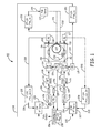
- FIG. 1 is a block diagram of one embodiment of a Resonator Fiber Optic Gyroscope (RFOG) system 10 with two lasers 105 and 106 in accordance with the present application.
- the lasers 105 and 106 are tunable lasers.
- High bandwidth resonance tracking loops reduce the relative frequency noise between the lasers 105 and 106 by stabilizing the lasers 105 and 106 to the same optical cavity, the gyro sensing resonator 150.
- the RFOG 10 includes a counter-clockwise (CCW) laser 105, a clockwise (CW) laser 106, a CCW modulator 111, a CW modulator 112, circulators 113 and 114, a gyroscope resonator 150 with ports 151-154, photodetectors 115, 116, 117, 118, and 119, a first-lock-in amplifier 251, a second-lock-in amplifier 252, a third-lock-in amplifier 253, a fourth-lock-in amplifier 254, a fifth-lock-in amplifier 255, a CW resonance tracking servo 206, a CCW resonance tracking servo 207, a free-spectral-range (FSR) servo 257, and a piezo-electric device (PZT) 260.
- CCW counter-clockwise
- CW clockwise
- CW modulator 111 e.g., CW modulator
- CW modulator 112 e.gyroscope
- the piezo-electric device 260 can be a lead zirconate titanate (PZT) device 260 that expands or shrinks under application of voltages.
- the RFOG 10 also includes couplers 107, 108, and 109 and a processing unit 259, which includes at least one processor configured to execute software to determine a rotation rate f r of the gyroscope resonator 150.
- the processing unit 259 outputs the rotation rate f r of the gyroscope resonator 150 (rate output).
- the CW modulator 112 is a CW phase modulator. In another implementation of this embodiment, the CW modulator 112 is a CW frequency modulator. In yet another implementation of this embodiment, the CCW modulator 111 is a CCW phase modulator. In yet another implementation of this embodiment, the CCW modulator 111 is a CCW frequency modulator.
- the gyroscope resonator 150 is also referred to herein as “sensing resonator 150", “gyroscope resonator coil 150", “gyro sensing resonator 150".
- the gyroscope resonator 150 can comprise a solid core optical fiber or a hollow optical fiber, plus two optical power splitting couplers (i.e., "resonator couplers” for coupling light into and out of the gyroscope resonator 150).
- the RFOG 10 is configured so the FSR of gyroscope resonator 150 is adjusted as required to lock to the frequency of fm_cw/(n+0.5), where fm_cw is the modulation frequency of CW optical beam 126.
- the RFOG 10 is configured so the FSR of gyroscope resonator 150 is adjusted as required to lock to the frequency of fm_ccw/(p+0.5), where fm_ccw is the modulation frequency of CCW optical beam 125.
- An implementation in which the modulation frequency of the CW optical beam 126 and the CW optical beam 125 are adjusted as required to lock to the FSR of the gyroscope resonator 150 is described below with reference to the RFOG 11 of Figure 5 .
- the port 151 is referred to herein as "counter-clockwise input port 151” and “CW transmission output port 151".
- the port 152 is referred to herein as “clockwise input port 152" and “CCW transmission output port 152".
- the port 153 is referred to herein as “CCW reflection output port 153".
- the port 154 is referred to herein as "CW reflection output port 154".
- the photodetector 115 is referred to herein as “CW transmission detector 115".
- the photodetector 116 is referred to herein as "CCW transmission detector 116".
- the photodetector 117 is referred to herein as “CCW reflection detector 117".
- the photodetector 118 is referred to herein as "CW reflection detector 118".
- the CW resonance tracking loop includes the CW laser 106, the CW modulator 112, the CW circulator 114, the gyroscope resonator 150, the CW reflection detector 118, the first-lock-in-amplifier 251, and the CW resonance tracking servo 206.
- the CCW resonance tracking loop includes the CCW laser 105, a CCW modulator 111, the CCW circulator 113, the gyroscope resonator 150, the CCW reflection detector 117, the fourth-lock-in-amplifier 254, and the CCW resonance tracking servo 207.
- An optical beam represented generally at 126 is emitted from the clockwise (CW) laser 106, passed through the CW modulator 112.
- the CW laser 106 is also referred to herein as “first laser 106".
- the optical beam 126 is also referred to herein as "clockwise optical beam 126", “CW light 126", and "CW beam 126".
- the CW modulator 112 modulates the clockwise optical beam 126 before the clockwise optical beam 126 is coupled into the clockwise input port 152 of the gyroscope resonator 150.
- the clockwise optical beam 126 output from the CW modulator 112 is passed through the optical circulator 114 to the gyroscope resonator 150 via the clockwise input port 152.
- the CW laser 106 is locked onto the resonance of the gyro resonator 150 with a high bandwidth feedback loop using Pound-Drever-Hall (PDH) modulation techniques that are known to those skilled in the art.
- the optical frequency of the laser 106 i.e., the carrier frequency f 1 of CW beam
- the optical frequency of the laser 106 is locked midway between a first clockwise longitudinal mode and a second clockwise longitudinal mode of the sensing resonator 150 as shown in Figure 2 and described below.
- An optical beam represented generally at 125 emitted from the counter-clockwise (CCW) laser 105 is passed through the CCW modulator 111.
- the CCW laser 105 is also referred to herein as “second laser 106".
- the optical beam 125 is also referred to herein as "counter-clockwise optical beam 125", “CCW beam 125”, and "CCW light 125".
- the modulator 111 modulates the counter-clockwise optical beam 125 before the counter-clockwise optical beam 125 is coupled into a counter-clockwise input port 151 of the gyroscope resonator 150.
- the counter-clockwise optical 125 beam output from the modulator 111 is passed through the optical circulator 113 to the gyroscope resonator 150 via the counter-clockwise input port 151.
- the CCW laser 105 is locked onto the resonance of the gyro resonator 150 with a high bandwidth feedback loop using the PDH method so the relative frequency noise between the CW laser 106, the CCW laser 105, and the gyro resonator 150 are substantially reduced when there is sufficient loop gain.
- the carrier frequency f 2 of the counter-clockwise optical beam 125 is locked midway between two longitudinal modes of the sensing resonator 150.
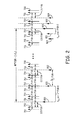
- Figure 2 shows exemplary vector arrows representing the frequency and amplitude of optical signals relative to resonance peaks of a gyro sensing resonator in accordance with the present application.
- the exemplary relations between various frequencies is indicated by the vector arrows 800- 802 and 820-824.
- the CW resonance peaks of a gyro sensing resonator 150 are represented generally as solid vector arrows 700 and the CCW resonance peaks of a gyro sensing resonator 150 are represented generally as dashed vector arrows 701.
- the frequency difference between neighboring vector arrows 700 and 701 is ⁇ f r which is proportional to the rotation rate of the gyro sensing resonator 150.
- the frequency and amplitude of the carrier at frequency f 1 of the CW optical signal is shown locked between two CW resonance peaks 700 of the gyro sensing resonator 150.
- the frequency and amplitude of the carrier at frequency f 2 of the CCW optical signal represented generally as the vector arrow 820 is shown locked between two CCW resonance peaks 710 of the gyro sensing resonator 150.
- the modulation generates sidebands.
- the first order upper sideband represented generally at 801 and the second order upper sideband represented generally at 802 are shown in Figure 2 . Since the carrier 800 of the CW optical signal 126 ( Figure 1 ) is modulated at 1.5 times the FSR of the gyro sensing resonator 150 the first order upper sideband 801 is offset from the carrier 800 by 1.5 times the FSR and the second order upper sideband 802 is offset from the carrier 800 by 3 times the FSR.
- the carrier 820 of the CCW optical signal 125 ( Figure 1 ) is modulated at 0.5 times the FSR of the gyro sensing resonator 150 (e.g., (p+0.5)FSR where p equals 0).
- the carrier 820 of the CCW optical signal 125 ( Figure 1 ) is modulated at 0.5 times the FSR of the gyro sensing resonator 150.
- the modulation generates first and second order, upper and lower sidebands about the optical carrier 820.
- the carrier 820 of the CCW optical signal 125 ( Figure 1 ) is offset from the first lower sideband represented generally at 821 by 1/2 FSR and from the first upper sideband represented generally at 822 by 1/2 FSR.
- the carrier 820 of the CCW optical signal 125 is offset from the second lower sideband represented generally at 823 by a single FSR and from the second upper sideband represented generally at 824 by a single FSR.
- the carrier 820 of the CCW optical signal 125 ( Figure 1 ) is separated in frequency from the carrier 800 of the CW optical signal 126 ( Figure 1 ) by (M*FSR- f r ), where f r is proportional to the rotation rate of the gyroscope resonator 150, and where M is much greater than n, and M is much greater than p.
- the symbol * is used herein to indicate multiplication.
- M is selected substantially large so that there are no overlaps in frequency of the CW and CCW carriers and the sidebands.
- the CW beam and the CCW beam have negligible energy at the same optical frequency, which is referred to herein as "no overlap in frequencies of the CW and CCW sidebands and carriers.
- the interference between any back reflection on the CW beam 126 and the CCW beam 125 or between any back reflection on the CCW beam 125 and the CW beam 126 can be easily filtered out.
- Other modulation frequencies can be selected to provide a condition of no significant overlap of the carrier and sideband frequencies of the CW and CCW beams.
- the optical beam 126 output from the CW laser 106 propagates clockwise through the gyro resonator 150 and passes, via the CW transmission port 151, through the circulator 113 to the CW transmission detector 115.
- the CW optical beam 126 from CW laser 106 is transmitted through gyro resonator 150 to reach transmission detector 115.
- a large portion of the optical beam 126 from the CW laser 106 that enters port 152 does not enter gyro resonator 150 and therefore is not transmitted through gyro resonator 150, but rather goes directly to CW reflection port 154, to be incident on the CW reflection detector 118.
- the portion of the optical beam that entered the gyro resonator 150 exits the gyro resonator 150 at reflection port 154 and interferes with the portion of the optical beam that did not enter the gyro resonator 150.
- the CW reflection detector 118 detects light from the CW reflection port 154 of the gyro resonator 150. Output from the CW reflection detector 118 is input to the first-lock-in-amplifier 251.
- the two resonator couplers are 10% couplers, that that couple 10% of the light from ports 152 and 151 to the resonator coil 150. In another implementation of this embodiment, the two resonator couplers are 20% couplers that couple 20% of the light from ports 152 and 151 to the resonator coil 150.
- the optical beam 125 output from the CCW laser 105 propagates counter-clockwise through the gyro resonator 150 and passes, via the CCW transmission port 152, through the circulator 114 to the CCW transmission detector 116.
- the optical beam 125 from CCW laser 105 must transmit through gyro resonator 150 to reach transmission detector 116.
- a portion of the optical beam from the CCW laser 105 that enters port 151 does not enter gyro resonator 150 and therefore does not transmit through gyro resonator 150, but rather goes directly to CCW reflection port 153 to be incident on the CCW reflection detector 117.
- the CCW reflection detector 117 detects light from the CCW reflection port 153 of the gyro resonator 150. Output from the CCW reflection detector 117 is input to the CCW fourth-lock-in-amplifier 254.
- the reflection port signals typically have fast response to changes of input beam frequencies.
- High bandwidth resonance tracking loop can be achieved by using reflection port signals as feedback signals.
- the line shape of the resonance peak of the optical beam output at the transmission ports 151 and 152 typically have significantly better symmetry than the line shape of the resonance dip of the optical beam output from the reflection ports 153 and 154.
- the transmission port signals can be used to correct the bias errors induced in the resonance tracking loops.
- a first resonance tracking loop includes the third lock-in amplifier 253 and the CW resonance tracking (RT) servo 206 while a second resonance tracking loop includes the fifth lock-in amplifier 255 and the CCW resonance tracking servo 205, as shown in Figure 1 .
- Figures 3A and 3B are flow diagrams of an embodiment of a method 300 to lock a free spectral range (FSR) of a gyroscope resonator in a resonator fiber optic gyroscope and a laser modulation frequency of an optical beam coupled to an input port of the gyroscope resonator with respect to each other in accordance with the present application.
- FSR free spectral range
- a clockwise optical beam 126 emitted from a laser 106 is modulated with a laser modulation frequency of (n+0.5) times the FSR of the gyroscope resonator, where n is zero or a positive integer.
- the modulated clockwise optical beam 126 is coupled into a clockwise input port 152 of the gyroscope resonator 150.
- the optical beam 126 output from the CW laser 106 propagates clockwise through the gyro resonator 150 and passes, via the CW transmission port 151, through the circulator 113 to the CW transmission detector 115.
- a large portion of the optical beam 126 from the CW laser 106 that enters port 152 does not enter gyro resonator 150 and therefore does not transmit through gyro resonator 150, but rather goes directly to CW reflection port 154, to be incident on the CW reflection detector 118.
- the CW reflection detector 118 detects light from the CW reflection port 154 of the gyro resonator 150. Output from the CW reflection detector 118 is input to the first-lock-in-amplifier 251.
- a signal 228 is received from a CW reflection detector 118 of the resonator fiber optic gyroscope system 10 at the first-lock-in-amplifier 251.
- a first harmonic (n+0.5)FSR of the signal 228 received from the CW reflection detector 118 is demodulated at the first-lock-in-amplifier 251.
- a demodulated first-harmonic signal 236 is received from the first-lock-in-amplifier 251 at a CW resonance tracking (RT) servo 206.
- RT CW resonance tracking
- feedback 237 is provided to the first laser 106 from the CW RT servo 206 in order to lock the first laser 106 to the gyroscope resonator 150.
- a signal 229 is received from a CW transmission detector 115 of the resonator fiber optic gyroscope system 10 at a second-lock-in-amplifier 252 and at a third-lock-in-amplifier 253.
- a second harmonic 2(n+0.5)FSR of the signal 229 received from the CW transmission detector 115 is demodulated at the second-lock-in-amplifier 252.
- feedback 244 is provided from the second-lock-in-amplifier 252 to a second servo 257, which is the FSR servo 257 in the embodiment of Figure 1 .
- the FSR servo 257 drives a piezo-electric transducer 260 (also referred to herein as the piezo-electric device 260) for resonator length adjustment.
- Figure 4 shows a simulation of the normalized power of a demodulated signal output from the second-lock-in-amplifier 252 in the RFOG system 10 of Figure 1 as a function of modulation frequency.
- the plot 410 is the demodulated signal coming out of the second-lock-in-amplifier 252 and is provided as feedback 244 to the FSR servo 257 (block 318).
- the FSR servo adjusts the resonator fiber length so that the FSR is kept at fm_cw/(n+0.5).
- feedback 231 is provided from the FSR servo 257 to the piezo-electric device 260 based on the feedback 244 from the second-lock-in-amplifier 252.
- the length of the gyroscope resonator coil 150 is adjusted by driving the piezo-electric device 260 based on the feedback 231 received from FSR servo 257.
- the piezo-electric device 260 applies pressure or stretches the resonator coil 150 as is known to one skilled in the art.
- a temperature control feedback signal 232 is provided from the FSR servo 257 to the gyroscope resonator 150 based on the feedback from the second-lock-in-amplifier 252.
- a first harmonic (n+0.5)FSR of the signal 229 received from the CW transmission detector 115 is demodulated at the third-lock-in-amplifier 253.
- feedback 238 is provided from the third-lock-in-amplifier 253 to the CW RT servo 206 to correct errors in the CW resonance tracking loop.
- the optical beam 127 detected by the CW transmission detector 115 at the CW transmit port 151 contains much less light from mismatched polarization and spatial modes than the optical beam 128 emitted the CW reflection port 154 since the optical beam 127 has been transmitted through the resonator 150. Therefore, the optical beam 127 is pure (i.e., has fewer light components that cause gyro errors).
- the demodulation of the optical beam 127 emitted from the CW transmit port 151 is used to correct errors in the CW resonance tracking loop by driving a bias point in the CW RT servo 206. This stabilizes the locking of the first laser 106 to the gyroscope resonator 150.
- the flow of method 300 is directed to block 326 in Figure 3B .
- the flow of method 300 is directed to block 328 in Figure 3B .
- a counter-clockwise optical beam 125 emitted from a second laser 105 is modulated with a modulation frequency of (p+0.5) times the FSR.
- p is zero or a positive integer and p does not equal n.
- the modulated counter-clockwise optical beam 125 is coupled into the counter-clockwise input port 151 of the gyroscope resonator 150.
- a signal 230 is received from a CCW reflection detector 117 of the resonator fiber optic gyroscope system 10 at the fourth-lock-in-amplifier 254.
- a first harmonic of the signal 230 received from the CCW reflection detector 117 is demodulated at the fourth-lock-in-amplifier 254.
- a demodulated first-harmonic signal 233 is received from the fourth-lock-in-amplifier 254 at a CCW resonance tracking servo 207.
- feedback 234 is provided to the second laser 105 from the CCW RT servo 207 to lock the second laser 105 to the gyroscope resonator 150.
- a signal 246 is received from the CCW transmission detector 116 of the resonator fiber optic gyroscope system 10 at the fifth-lock-in-amplifier 255.
- the optical beam 129 output from the CCW transmit port 152 is detected by the CCW transmission detector 116.
- a first harmonic at (p+0.5)FSR of the signal 246 received from the CCW transmission detector 116 is demodulated at the fifth-lock-in-amplifier 255.
- feedback from the fifth-lock-in-amplifier 255 is provided to the CCW RT servo 207 to correct errors in the CCW RT loop.
- the demodulation of the optical beam 129 detected by the detector 116 is used to correct errors in the CCW resonance tracking loop by driving a bias point in the CCW RT servo 207. This stabilizes the locking of the second laser 105 to the gyroscope resonator 150.
- the FSR corresponding to the resonator round trip length is locked through the FSR servo 257 to the modulation frequency of the CW optical beam 126 emitted from the first laser 106.
- the first laser 106 is modulated by a precision modulation frequency source. Additionally, the modulation frequency of the CCW optical beam 125 emitted from the second laser 105 is locked to the FSR.
- the technique described herein does not need to measure the FSR of the gyroscope resonator 150 to calculate the rotation rate. All error terms related to a change in FSR of the gyroscope resonator 150 are removed. Specifically, since the FSR can be obtained from the modulation frequency of the first laser 106, the influence of the FSR on rotation rate measurement can be easily subtracted out.
- a portion of the clockwise optical beam combined with a portion of the counter-clockwise optical beam is received a photodetector 119.
- Information indicative of a beat signal generated from the combined optical beams is output from the photodetector 119.
- the processing unit calculates a rotation rate f r based on, at least, the beat signal from the photodetector 119.
- a rotation rate f r based on, at least, the beat signal from the photodetector 119.
- a fraction of CW light 126 and CCW light 125 are tapped from the laser outputs and combined at a high bandwidth detector 119 to determine the carrier frequency difference ⁇ f between the CW beam 126 and CCW beam 125.
- FIG. 5 is a block diagram of one embodiment of a Resonator Fiber Optic Gyroscope (RFOG) system 11 with two lasers 105 and 106 in accordance with the present application.
- the RFOG system 11 adjusts the modulation frequency of the CW optical beam 126 and the CW optical beam 125 as required to lock to the FSR of the gyroscope resonator 150.
- the RFOG 11 is configured so the modulation frequency of the CCW optical beam 125 is adjusted as required to lock to a CCW frequency modulation fm ccw equal to (p+0.5)FSR and, at the same time, the modulation frequency of the CW optical beam 126 is adjusted as required to lock to a CW frequency modulation fm_cw equal to (n+0.5)FSR, where n and p are zero or a positive integer, and p does not equal n.
- the lasers 105 and 106 are tunable lasers.
- High bandwidth resonance tracking loops control the relative laser frequency noise between the lasers 105, 106 and the resonator by stabilizing the lasers 105 and 106 to the gyro sensing resonator.
- the free spectral range (FSR) of a gyroscope resonator 150 in the RFOG system 10 and a laser modulation frequency of an optical beam 126 coupled to an input port 152 of the gyroscope resonator 150 are locked to each other.
- the RFOG system 11 includes a counter-clockwise (CCW) laser 105, a clockwise (CW) laser 106, a CCW modulator 111, a CW modulator 112, circulators 113 and 114, a gyroscope resonator 150 with ports 151-154, photodetectors 115, 116, 117, 118, and 119, a first-lock-in amplifier 251, a second-lock-in amplifier 252, a third-lock-in amplifier 253, a fourth-lock-in amplifier 254, a fifth-lock-in amplifier 255, a CW resonance tracking servo 206, a CCW resonance tracking servo 207, a modulation-frequency servo 258, couplers 107, 108, and 109, and a processing unit 259.
- the RFOG system 11 also includes a clockwise tunable modulation generator 102 to drive the clockwise modulator 112 and a counter-clockwise tunable modulation 101 to drive the counter-clockwise
- the clockwise tunable modulation generator 102 is also referred to herein as “CW frequency modulation source 102" used to drive a CW frequency modulator 112.
- the counter-clockwise tunable modulation 101 is also referred to herein as “CCW frequency modulation source 101” used to drive a CCW frequency modulator 111.
- the clockwise tunable modulation generator 102 is also referred to herein as “CW phase modulation source 102" used to drive a CW phase modulator 112.
- the counter-clockwise tunable modulation 101 is also referred to herein as “CCW phase modulation source 102” used to drive a CCW phase modulator 111.
- the RFOG system 11 differs from the RFOG system 10 of Figure 1 in that the second servo is a modulation-frequency servo 258 rather than a FSR servo 257.
- the modulation-frequency servo 258 provides feedback signals 241 and 242 to CW frequency modulation source 102 and CCW frequency modulation source 101, respectively.
- the CW frequency modulation source 102 is a precise frequency modulation source that modulates the CW optical beam 126 emitted from the CW laser 106.
- the CCW frequency modulation source 101 is a precise frequency modulation source that modulates the CCW optical beam 125 emitted from the CCW laser 105.
- the CW frequency modulation source 102 adjusts the modulation frequency of the CW laser 106 based on the feedback signal 241.
- the modulation-frequency servo 258 locks the CW modulation frequency to (n+0.5)FSR, where n is zero or a positive integer.
- the CCW frequency modulation source 101 also adjusts the modulation frequency of the CCW laser 105 based on the feedback signal 242.
- the modulation-frequency servo 258 locks the CCW modulation frequency to (p+0.5)FSR, where p is zero or a positive integer that not equal to m.
- the clockwise resonance tracking loop in the RFOG system 11 is the same as the clockwise resonance tracking loop in the RFOG system 10.
- the counter-clockwise resonance tracking loop in the RFOG system 11 is the same as the counter-clockwise resonance tracking loop in the RFOG system 10.
- the method 300 of Figures 3A and 3B is implemented in the RFOG system 11 as follows.
- feedback 240 is provided from the second-lock-in-amplifier 252 to a second servo 258, which is the modulation-frequency servo 258 in the embodiment of Figure 5 .
- the modulation-frequency servo 258 provides feedback 241 to the CW tunable modulation generator 102 based on the feedback 240 from the second-lock-in-amplifier 252.
- CW tunable modulation generator 102 adjusts the modulation frequency of the CW optical beam 126 as the FSR changes in order to lock the modulation frequency of the CW optical beam 126 to the (n+0.5)FSR.
- the modulation-frequency servo 258 also provides feedback to the CCW tunable modulation generator 101 based on the feedback 240 from the second-lock-in-amplifier 252.
- the CCW tunable modulation generator 101 adjusts the modulation frequency of the CCW optical beam 125 as the FSR changes to lock the modulation frequency of the CCW optical beam 125 to (p+0.5)FSR. In this manner, the modulation frequency (n+0.5)FSR of the CW optical beam 126 is locked to the FSR of the gyroscope resonator 150 through the second servo 258.
- a second servo 257 which is the
- inventions of systems described herein allow for selection of modulation frequencies at substantially high values so that laser RIN noise and phase noise are substantially attenuated by the filtering effect of the sensing coil.
- Example 1 includes a resonator fiber optic gyroscope system, comprising: a gyroscope resonator having a clockwise input port and a counter-clockwise input port and a free spectral range (FSR) corresponding to the resonator round trip length; a laser configured to couple a clockwise optical beam into to the clockwise input port; a clockwise modulator to impose a modulation frequency equivalent to (n+0.5) times the FSR on the clockwise optical beam before the clockwise optical beam is coupled into the clockwise input port, where n is zero or a positive integer; a clockwise circulator; a clockwise reflection detector to detect the clockwise optical beam output from a clockwise reflection port; a first-lock-in-amplifier to receive a signal from the clockwise reflection detector, wherein the first-lock-in-amplifier demodulates at the first harmonic of the modulation frequency of the clockwise optical beam; a clockwise-resonance-tracking servo to receive output from the first
- Example 2 includes the resonator fiber optic gyroscope system of Example 1, wherein the laser is a first laser, further comprising: a second laser configured to couple a counter-clockwise optical beam into to the counter-clockwise input port; a counter-clockwise modulator to impose a modulation frequency equivalent to (p+0.5) times the FSR on the counter-clockwise optical beam before the counter-clockwise optical beam is coupled into the counter-clockwise input port, where p is zero or a positive integer and where p does not equal n; a counter-clockwise circulator; a counter-clockwise reflection detector to detect the counter-clockwise optical beam output from a counter-clockwise reflection port; a fourth-lock-in-amplifier to receive a signal from the counter-clockwise reflection detector, wherein the fourth-lock-in-amplifier demodulates at the first harmonic of the modulation frequency of the counter-clockwise optical beam; a counter-clockwise-resonance-tracking servo to receive output from the fourth-lock-in
- Example 3 includes the resonator fiber optic gyroscope system of Example 2, wherein the second servo is a free-spectral-range (FSR) servo, the resonator fiber optic gyroscope system further comprising: a piezo-electric device to input feedback from the FSR servo, wherein a length of a gyroscope resonator coil is changed by the piezo-electric device to adjust the FSR of the gyroscope resonator in order to lock the FSR in relation to the modulation frequency of the clockwise optical beam.
- FSR free-spectral-range
- Example 4 includes the resonator fiber optic gyroscope system of Example 3, wherein FSR servo further provides a temperature control signal to the gyroscope resonator based on the feedback from the second-lock-in-amplifier.
- Example 5 includes the resonator fiber optic gyroscope system of any of Examples 2-4, wherein the second servo is a modulation-frequency servo, the resonator fiber optic gyroscope system further comprising: a clockwise tunable modulation generator to drive the clockwise modulator; and a counter-clockwise tunable modulation generator to drive the counter-clockwise modulator, wherein the clockwise tunable modulation generator receives feedback from the modulation-frequency servo to adjust the modulation frequency of the clockwise optical beam as the FSR changes in order to lock the modulation frequency of the clockwise optical beam to the (n+ 0.5)FSR, and wherein the counter-clockwise tunable modulation generator receives feedback from the modulation-frequency servo to adjust the modulation frequency of the counter-clockwise optical beam as the FSR changes in order to lock the modulation frequency of the counter-clockwise optical beam to (p+0.5)FSR.
- the clockwise tunable modulation generator receives feedback from the modulation
- Example 6 includes the resonator fiber optic gyroscope system of any of Examples 1-5, wherein the second servo is a FSR servo, the resonator fiber optic gyroscope system further comprising: a piezo-electric device to input feedback from the FSR servo, wherein a length of a gyroscope resonator coil is changed by the piezo-electric device to adjust the FSR of the gyroscope resonator in order to lock the FSR in relation to the modulation frequency of the clockwise optical beam.
- the second servo is a FSR servo
- the resonator fiber optic gyroscope system further comprising: a piezo-electric device to input feedback from the FSR servo, wherein a length of a gyroscope resonator coil is changed by the piezo-electric device to adjust the FSR of the gyroscope resonator in order to lock the FSR in relation to
- Example 7 includes the resonator fiber optic gyroscope system of any of Examples 1-6, wherein the second servo is a modulation-frequency servo, the resonator fiber optic gyroscope system further comprising: a clockwise tunable modulation generator configured to drive the clockwise phase modulator, wherein the clockwise tunable modulation generator receives feedback from the modulation-frequency servo to adjust the modulation frequency of the clockwise optical beam as the FSR changes in order to lock the modulation frequency of the clockwise optical beam to the (n+0.5)FSR.
- a clockwise tunable modulation generator configured to drive the clockwise phase modulator
- the clockwise tunable modulation generator receives feedback from the modulation-frequency servo to adjust the modulation frequency of the clockwise optical beam as the FSR changes in order to lock the modulation frequency of the clockwise optical beam to the (n+0.5)FSR.
- Example 8 includes the resonator fiber optic gyroscope system of any of Examples 1-7, further comprising: a photodetector to receive a portion of the clockwise optical beam combined with a portion of the counter-clockwise optical beam to generate a beat signal from the combined optical beams; and a processing unit to calculate a rotation rate based on at least the beat signal.
- Example 9 includes a method of locking a free spectral range (FSR) of a gyroscope resonator in a resonator fiber optic gyroscope system and a laser modulation frequency of an optical beam coupled to an input port of the gyroscope resonator to each other, the method comprising: modulating a clockwise optical beam emitted from a laser with a laser modulation frequency of (n+0.5) times the FSR, where n is zero or a positive integer; coupling the modulated clockwise optical beam into a clockwise input port of the gyroscope resonator; receiving a signal from a clockwise reflection detector; demodulating a first harmonic of the signal received from the clockwise reflection detector at a first-lock-in-amplifier; receiving a demodulated first-harmonic signal from the first-lock-in-amplifier at a clockwise-resonance-tracking servo; providing feedback to the laser from the clockwise-resonance-tracking
- Example 10 includes the method of Example 9, wherein the laser is a first laser, the method further comprising: modulating a counter-clockwise optical beam emitted from a second laser with a laser modulation frequency of (p+0.5) times the FSR, where p is zero or a positive integer and p does not equal n; coupling the modulated counter-clockwise optical beam into a counter-clockwise input port of the gyroscope resonator; receiving a signal from a counter-clockwise reflection detector at a fourth-lock-in-amplifier; demodulating a first harmonic of the signal received from the counter-clockwise reflection detector at the fourth-lock-in-amplifier; receiving a demodulated first-harmonic signal from the fourth-lock-in-amplifier at a counter-clockwise-resonance-tracking servo; and providing feedback to the second laser from the counter-clockwise-resonance-tracking servo to lock the second laser to the gyroscope resonator.
- Example 11 includes the method of Example 10, further comprising: receiving a signal from counter-clockwise transmission detector at a fifth-lock-in-amplifier; demodulating a first harmonic of the signal received from the counter-clockwise transmission detector at the fifth-lock-in-amplifier; and providing feedback from the fifth-lock-in-amplifier to the counter-clockwise-resonance-tracking servo to correct errors in the counter-clockwise resonance tracking loop.
- Example 12 includes the method of any of Examples 10-11, wherein the second servo is a FSR servo, the method further comprising: providing feedback from the FSR servo to a piezo-electric device based on the feedback from the second-lock-in-amplifier; adjusting a length of a gyroscope resonator coil by driving the piezo-electric device based on the feedback received at the FSR device; and locking the FSR to 1/(n+0.5) times the modulation frequency of the clockwise optical beam through the adjustment to the length of the gyroscope resonator coil.
- the second servo is a FSR servo
- the method further comprising: providing feedback from the FSR servo to a piezo-electric device based on the feedback from the second-lock-in-amplifier; adjusting a length of a gyroscope resonator coil by driving the piezo-electric device based on the feedback received at the FSR device; and locking the
- Example 13 includes the method of Example 12, further comprising: providing a temperature control signal to the gyroscope resonator from the FSR servo based on the feedback from the second-lock-in-amplifier.
- Example 14 includes the method of any of Examples 10-13, wherein the second servo is a modulation-frequency servo, the method further comprising: providing feedback from the modulation-frequency servo to a clockwise tunable modulation generator based on the feedback from the second-lock-in-amplifier; adjusting the modulation frequency of the clockwise optical beam as the FSR changes to lock the modulation frequency of the clockwise optical beam to the (n+ 0.5)FSR; providing feedback from the modulation-frequency servo to a counter-clockwise tunable modulation generator based on the feedback from the second-lock-in-amplifier; and adjusting the modulation frequency of the counter-clockwise optical beam as the FSR changes to lock the modulation frequency of the counter-clockwise optical beam to (p+0.5)FSR.
- Example 15 includes the method of any of Examples 9-14, wherein the second servo is a FSR servo, the method further comprising: providing feedback from the FSR servo to a piezo-electric device based on the feedback from the second-lock-in-amplifier; adjusting a length of a gyroscope resonator coil by implementing the piezo-electric device based on the feedback received at the piezo-electric device; and locking the FSR to the modulation frequency of the clockwise optical through the adjustment to the length of the gyroscope resonator coil.
- the second servo is a FSR servo
- the method further comprising: providing feedback from the FSR servo to a piezo-electric device based on the feedback from the second-lock-in-amplifier; adjusting a length of a gyroscope resonator coil by implementing the piezo-electric device based on the feedback received at the piezo-electric device; and locking the F
- Example 16 includes the method of Example 15, further comprising: providing a temperature control signal to the gyroscope resonator from the FSR servo based on the feedback from the second-lock-in-amplifier.
- Example 17 includes the method of any of Examples 9-16, wherein the second servo is a modulation-frequency servo, the resonator fiber optic gyroscope further comprises: providing feedback from the modulation-frequency servo to a clockwise tunable modulation generator based on the feedback from the second-lock-in-amplifier; adjusting the modulation frequency of the clockwise optical beam as the FSR changes to lock the modulation frequency of the clockwise optical beam to the (n+0.5)FSR; providing feedback from the modulation-frequency servo to a counter-clockwise tunable modulation generator based on the feedback from the second-lock-in-amplifier; and adjusting the modulation frequency of the counter-clockwise optical beam as the FSR changes to lock the modulation frequency of the counter-clockwise optical beam to (p+0.5)FSR.
- Example 18 includes a resonator fiber optic gyroscope system, comprising: a gyroscope resonator having a clockwise input port and a counter-clockwise input port and a free spectral range (FSR) corresponding to the resonator round trip length; a first laser configured to couple a clockwise optical beam into to the clockwise input port; a clockwise modulator to impose a modulation frequency equivalent to (n+0.5) times the FSR on the clockwise optical beam before the clockwise optical beam is coupled into the clockwise input port, where n is a positive integer; a clockwise circulator; a clockwise reflection detector to detect the clockwise optical beam output from a clockwise reflection port; a first-lock-in-amplifier to receive a signal from the clockwise reflection detector, wherein the first-lock-in-amplifier demodulates at the first harmonic of the modulation frequency of the clockwise optical beam; a clockwise-resonance-tracking servo to receive output from the first-
- Example 19 includes the resonator fiber optic gyroscope system of Example 18, wherein the second servo is a FSR servo, the resonator fiber optic gyroscope system further comprising: a piezo-electric device to input feedback from the FSR servo, wherein a length of a gyroscope resonator coil is changed by the piezo-electric device to adjust the FSR of the gyroscope resonator based on the feedback from the FSR servo to lock the FSR in relation to the modulation frequency of the clockwise optical beam.
- the second servo is a FSR servo
- the resonator fiber optic gyroscope system further comprising: a piezo-electric device to input feedback from the FSR servo, wherein a length of a gyroscope resonator coil is changed by the piezo-electric device to adjust the FSR of the gyroscope resonator based on the
- Example 20 includes the resonator fiber optic gyroscope system of any of Examples 18-19, wherein the second servo is a modulation-frequency servo, the resonator fiber optic gyroscope system further comprising: a clockwise tunable modulation generator to drive the clockwise phase modulator; and a counter-clockwise modulation to drive the counter-clockwise phase modulator, wherein the clockwise tunable modulation generator receives feedback from the modulation-frequency servo to adjust the modulation frequency of the clockwise optical beam as the FSR changes, wherein the modulation frequency of the clockwise optical beam is locked to the (n+0.5)FSR, and wherein the counter-clockwise tunable modulation generator receives feedback from the modulation-frequency servo to adjust the modulation frequency of the counter-clockwise optical beam as the FSR changes, wherein the modulation frequency of the counter-clockwise optical beam is locked to (p+0.5)FSR.
- the clockwise tunable modulation generator receives feedback from the modulation-
Description
- The Resonator Fiber Optic Gyroscope (RFOG) has the potential of meeting the needs in many areas of the inertial sensing market. To overcome optical backscatter errors, currently available RFOGs lock the clockwise (CW) and counter-clockwise (CCW) laser frequencies onto different longitudinal modes of the gyro sensing resonator. These technologies separate the counter-propagating laser frequencies and up-convert the interference signals between counter-propagating lightwaves well above the rotation measurement frequency band. However, if only two lasers are used, the gyro sensing resonator free spectral range (FSR) becomes a part the rotation measurement. Thus, in prior art RFOGs, the gyro sensing resonator free spectral range must be measured with great precision to reduce the adverse effects caused by FSR variations and more than two lasers are typically used.
- To avoid interference between the CW and CCW light, which happens due to back reflection when lasers are locked to the same resonance at low rotation rate, the prior art uses methods of locking three or more lasers to three different resonances. To accurately measure the FSR, currently available RFOGs use a third laser frequency to probe the sensing resonator. Resonance frequencies of the gyro resonator must be precisely measured to obtain an accurate measure of the FSR and rotation. Modulation is used for detecting the resonance frequency. For a master/two slave configuration, it is difficult to modulate all three lasers to detect resonance in a way that modulation imperfections do not cause large errors. Slave lasers can be modulated with high precision by using digital techniques combined with high gain optical phase lock loops, but it is difficult to modulate the master laser with high precision since the modulation eventually becomes an open loop analog current or voltage.
- Other currently available RFOGs use a master laser and three slave lasers. In this latter technology, the master laser is not used for rotation sensing and the three slave lasers are modulated with high precision. However, the number of lasers and associated phase lock loop electronics results in a significant increase in the cost, size, weight, and electrical power consumption of the RFOG.
- Thus, an RFOG that requires only two lasers for rate measurement without errors when the FSR of the gyro sensing resonator changes (due to temperature fluctuations and the like) is preferred
- A resonator fiber optic gyroscope system with a modulated clockwise optical beam, a clockwise reflection detector to detect the clockwise optical beam output, a lock-in-amplifier demodulating a signal from the clockwise reflection detector at the first harmonic of the modulation frequency of the clockwise optical beam, and a clockwise-resonance-tracking servo to receive output from the first-lock-in-amplifier and to provide feedback to the laser to lock the laser to the gyroscope resonator is disclosed in the prior art document
EP1795865A2 . - The present application relates to a resonator fiber optic gyroscope. The resonator fiber optic gyroscope includes a gyroscope resonator having a clockwise input port and a counter-clockwise input port and a free spectral range (FSR) corresponding to the resonator round trip length; a laser configured to couple a clockwise optical beam into to the clockwise input port; a clockwise modulator to impose a modulation frequency equivalent to (n+0.5) times the FSR on the clockwise optical beam before the clockwise optical beam is coupled into the clockwise input port, where n is zero or a positive integer; a clockwise circulator; a clockwise reflection detector to detect the clockwise optical beam output from a clockwise reflection port; a first-lock-in-amplifier to receive a signal from the clockwise reflection detector; a clockwise-resonance-tracking servo to receive output from the first-lock-in-amplifier and to provide feedback to the laser to lock the laser to the gyroscope resonator; a clockwise transmission detector to detect an optical beam output from the counter-clockwise input port; a second servo; a second-lock-in-amplifier to receive a signal from the clockwise transmission detector; and a third-lock-in-amplifier to receive a signal from the clockwise transmission detector. The first-lock-in-amplifier demodulates at the first harmonic of the modulation frequency of the clockwise optical beam. The second-lock-in-amplifier demodulates at the second harmonic of the modulation frequency of the clockwise optical beam and provides feedback to the second servo. The third-lock-in-amplifier demodulates at the first harmonic of the modulation frequency of the clockwise optical beam and provides feedback to the clockwise-resonance-tracking servo to correct errors in a clockwise resonance tracking loop. Either the modulation frequency of the clockwise optical beam is locked to (n+0.5) times the FSR through the second servo, where n is zero or a positive integer, or the FSR is locked to 1/(n + 0.5) times the modulation frequency of the clockwise optical beam through the second servo.
-
-
Figure 1 is a block diagram of one embodiment of a Resonator Fiber Optic Gyroscope (RFOG) system with two lasers in accordance with the present application; Attorney Docket No. H0040880-5704 -
Figure 2 shows exemplary vector arrows representing the frequency and amplitude of optical signals relative to resonance peaks of a gyro sensing resonator in accordance with the present application; -
Figures 3A and3B are flow diagrams of an embodiment of a method to lock a free spectral range (FSR) of a gyroscope resonator in a resonator fiber optic gyroscope and a laser modulation frequency of an optical beam coupled to an input port of the gyroscope resonator to each other in accordance with the present application; -
Figure 4 shows a simulation of the normalized power of a demodulated signal output from the second-lock-in-amplifier in the RFOG system ofFigure 1 as a function of frequency; and -
Figure 5 is a block diagram of one embodiment of a Resonator Fiber Optic Gyroscope (RFOG) system with two lasers in accordance with the present application. - In accordance with common practice, the various described features are not drawn to scale but are drawn to emphasize features relevant to the present application. Like reference characters denote like elements throughout figures and text.
- In the following detailed description, reference is made to the accompanying drawings that form a part hereof, and in which is shown by way of illustration specific illustrative embodiments in which the invention may be practiced. These embodiments are described in sufficient detail to enable those skilled in the art to practice the invention, and it is to be understood that other embodiments may be utilized and that logical, mechanical and electrical changes may be made without departing from the scope of the present application. The following detailed description is, therefore, not to be taken in a limiting sense.
- The RFOG systems described herein employ laser frequency (or phase) modulation and demodulation schemes that reduce the number of required lasers to two. The resonator fiber optic gyroscope (RFOG) system described herein uses only two lasers that are locked to separate resonances. The free spectral range (FSR) of the resonator in the RFOG and a laser modulation frequency of the optical beams coupled to the gyroscope resonator are locked with each other. Advantageously, the RFOG system described herein removes the need for a third laser to measure the FSR in order to determine the rotation rates. Since the lasers are locked to different resonance frequencies, the backscatter errors are reduced.
- The two input laser beams are frequency or phase modulated at (n+0.5)FSR, where n is an integer number, and FSR is the free spectral range determined by the resonator round trip length. The FSR typically ranges from a few hundred kHz to 100 MHz. The resonance tracking modulation is set at high frequency by proper selection of the number n. A typical modulation frequency can be 10 MHz or higher. When the modulation is set at these high frequencies, the impact of laser intrinsic relative intensity noise (RIN) is normally very low. In addition, laser phase noise induced RIN at high frequencies can be controlled by passive optical filters. The high speed RIN servos used in prior art RFOGs can thus be eliminated, the optical loss in the RFOG is therefore reduced, and the laser power required for the RFOG is reduced. In addition, high frequency phase noise can be controlled entirely with passive filtering of the gyroscope resonator. In one implementation of this embodiment, at least some passive filtering of both RIN and laser phase noise is achieved with an unbalanced Mach Zehnder interferometer instead of a cavity. This latter embodiment provides lower optical loss, reduced laser power, and simplified filter control electronics.
- In the RFOG systems described herein, the modulation frequency of the CW optical beam and the FSR of the gyroscope resonator are locked to each other in one of two ways. In one implementation of this embodiment, the modulation frequency of the CW optical beam is locked to the (n+0.5)FSR of the gyroscope resonator, while the modulation frequency of a CCW optical beam is locked to (p+0.5)FSR of the gyroscope resonator, where each of p and n are zero or a positive integer, and where p does not equal n. In another implementation of this embodiment, the FSR of the gyroscope resonator is adjusted so that it equals the modulation frequency of a CW optical beam divided by (n+0.5), i.e., FSR = fm/(n+0.5), where fm is the modulation frequency of the CW optical beam. In yet another implementation of this embodiment, with the modulation frequency of a CCW optical beam locked to (p+0.5)FSR of the gyroscope resonator (p and n are zero or a positive integer and p does not equal n), the FSR of the gyroscope resonator is adjusted so that it equals the modulation frequency of the CCW optical beam divided by (p+0.5), i.e., FSR = fm/(p+0.5), where fm is the modulation frequency of the CCW optical beam. The terms "optical beam", "beam", and optical signal" are interchangeably herein. The terms "frequency modulation", "phase modulation" and simply "modulation" are interchangeably herein.
- At least one resonance tracking loop (e.g., a CW resonance tracking loop) includes a resonance tracking (RT) servo that adjusts the CW laser optical frequency (or wavelength) based on feedback from both a CW reflection port detector and a CW transmission port detector. Part of the light in the optical beam detected at the CW reflection port detector is not passed through the gyroscope resonator. All of the light in the optical beam detected at the CW transmit port detector has been transmitted through the resonator. Thus, the signal based on output from the CW transmit port detector is cleaner (i.e., has less of the wrong polarization state of light) than the signal from the CW reflection detector. The reflection port detector signal has a quick response to transients (in other words: high bandwidth) and is fed back to a Pound-Drever-Hall (PDH) servo loop to achieve a tight lock of the lasers to the resonator. The terms "transmit port detector" and "transmission detector" are used interchangeably herein.
- Feedback based on the output from the CW transmit port detector is used to compensate bias errors in the CW resonance tracking loop by driving the PDH loop integrator bias to remove the error. As is understandable to one skilled in the art, the same process can be applied to a CCW resonance tracking loop in place of the CW resonance tracking loop. In one implementation of this embodiment, feedback can be applied to the CCW resonance tracking loop to correct errors in a CCW resonance tracking loop.
- The terms "sensing resonator", "gyroscope resonator coil", "gyro sensing resonator" and "gyroscope resonator" are used interchangeably herein.
-
Figure 1 is a block diagram of one embodiment of a Resonator Fiber Optic Gyroscope (RFOG)system 10 with twolasers lasers lasers lasers gyro sensing resonator 150. The free spectral range (FSR) of agyroscope resonator 150 in theRFOG system 10 and a CW laser modulation frequency fm cw of anoptical beam 126 coupled to aninput port 152 of thegyroscope resonator 150 are locked to each other through relationship of fm_cw = (n+0.5)FSR, where n is zero or a positive integer. - The
RFOG 10 includes a counter-clockwise (CCW)laser 105, a clockwise (CW)laser 106, aCCW modulator 111, aCW modulator 112,circulators gyroscope resonator 150 with ports 151-154,photodetectors amplifier 251, a second-lock-inamplifier 252, a third-lock-inamplifier 253, a fourth-lock-inamplifier 254, a fifth-lock-inamplifier 255, a CWresonance tracking servo 206, a CCWresonance tracking servo 207, a free-spectral-range (FSR)servo 257, and a piezo-electric device (PZT) 260. As is known to one skilled in the art, the piezo-electric device 260 can be a lead zirconate titanate (PZT)device 260 that expands or shrinks under application of voltages. TheRFOG 10 also includescouplers gyroscope resonator 150. The processing unit 259 outputs the rotation rate fr of the gyroscope resonator 150 (rate output). - In one implementation of this embodiment, the
CW modulator 112 is a CW phase modulator. In another implementation of this embodiment, theCW modulator 112 is a CW frequency modulator. In yet another implementation of this embodiment, theCCW modulator 111 is a CCW phase modulator. In yet another implementation of this embodiment, theCCW modulator 111 is a CCW frequency modulator. - The
gyroscope resonator 150 is also referred to herein as "sensingresonator 150", "gyroscope resonator coil 150", "gyro sensing resonator 150". Thegyroscope resonator 150 can comprise a solid core optical fiber or a hollow optical fiber, plus two optical power splitting couplers (i.e., "resonator couplers" for coupling light into and out of the gyroscope resonator 150). In one implementation of this embodiment, theRFOG 10 is configured so the FSR ofgyroscope resonator 150 is adjusted as required to lock to the frequency of fm_cw/(n+0.5), where fm_cw is the modulation frequency of CWoptical beam 126. In another implementation of this embodiment, theRFOG 10 is configured so the FSR ofgyroscope resonator 150 is adjusted as required to lock to the frequency of fm_ccw/(p+0.5), where fm_ccw is the modulation frequency of CCWoptical beam 125. An implementation in which the modulation frequency of the CWoptical beam 126 and the CWoptical beam 125 are adjusted as required to lock to the FSR of thegyroscope resonator 150 is described below with reference to theRFOG 11 ofFigure 5 . - The
port 151 is referred to herein as "counter-clockwise input port 151" and "CWtransmission output port 151". Theport 152 is referred to herein as "clockwise input port 152" and "CCWtransmission output port 152". Theport 153 is referred to herein as "CCWreflection output port 153". Theport 154 is referred to herein as "CWreflection output port 154". Thephotodetector 115 is referred to herein as "CW transmission detector 115". Thephotodetector 116 is referred to herein as "CCW transmission detector 116". Thephotodetector 117 is referred to herein as "CCW reflection detector 117". Thephotodetector 118 is referred to herein as "CW reflection detector 118". - The CW resonance tracking loop includes the
CW laser 106, theCW modulator 112, theCW circulator 114, thegyroscope resonator 150, theCW reflection detector 118, the first-lock-in-amplifier 251, and the CWresonance tracking servo 206. The CCW resonance tracking loop includes theCCW laser 105, aCCW modulator 111, theCCW circulator 113, thegyroscope resonator 150, theCCW reflection detector 117, the fourth-lock-in-amplifier 254, and the CCWresonance tracking servo 207. - An optical beam represented generally at 126 is emitted from the clockwise (CW)
laser 106, passed through theCW modulator 112. TheCW laser 106 is also referred to herein as "first laser 106". Theoptical beam 126 is also referred to herein as "clockwiseoptical beam 126", "CW light 126", and "CW beam 126". The CW modulator 112 modulates the clockwiseoptical beam 126 before the clockwiseoptical beam 126 is coupled into theclockwise input port 152 of thegyroscope resonator 150. The clockwiseoptical beam 126 output from theCW modulator 112 is passed through theoptical circulator 114 to thegyroscope resonator 150 via theclockwise input port 152. TheCW laser 106 is locked onto the resonance of thegyro resonator 150 with a high bandwidth feedback loop using Pound-Drever-Hall (PDH) modulation techniques that are known to those skilled in the art. The CW light 126 is modulated and demodulated at frequency fm_cw = (n+0.5)FSR. By proper setting of the lock-inamplifier 251 phase, the optical frequency of thelaser 106, (i.e., the carrier frequency f1 of CW beam) is locked midway between a first clockwise longitudinal mode and a second clockwise longitudinal mode of thesensing resonator 150 as shown inFigure 2 and described below. - An optical beam represented generally at 125 emitted from the counter-clockwise (CCW)
laser 105 is passed through theCCW modulator 111. TheCCW laser 105 is also referred to herein as "second laser 106". Theoptical beam 125 is also referred to herein as "counter-clockwiseoptical beam 125", "CCW beam 125", and "CCW light 125". Themodulator 111 modulates the counter-clockwiseoptical beam 125 before the counter-clockwiseoptical beam 125 is coupled into acounter-clockwise input port 151 of thegyroscope resonator 150. The counter-clockwise optical 125 beam output from themodulator 111 is passed through theoptical circulator 113 to thegyroscope resonator 150 via thecounter-clockwise input port 151. TheCCW laser 105 is locked onto the resonance of thegyro resonator 150 with a high bandwidth feedback loop using the PDH method so the relative frequency noise between theCW laser 106, theCCW laser 105, and thegyro resonator 150 are substantially reduced when there is sufficient loop gain. Specifically, theCCW laser 105 is modulated and demodulated at fm_ccw = (p+0.5)FSR with a high bandwidth feedback loop using the PDH method. Similar to the case of clockwiseoptical beam 126, the carrier frequency f2 of the counter-clockwiseoptical beam 125 is locked midway between two longitudinal modes of thesensing resonator 150. -
Figure 2 shows exemplary vector arrows representing the frequency and amplitude of optical signals relative to resonance peaks of a gyro sensing resonator in accordance with the present application. The exemplary relations between various frequencies is indicated by the vector arrows 800- 802 and 820-824. The CW resonance peaks of agyro sensing resonator 150 are represented generally assolid vector arrows 700 and the CCW resonance peaks of agyro sensing resonator 150 are represented generally as dashedvector arrows 701. The frequency difference between neighboringvector arrows gyro sensing resonator 150. - The frequency and amplitude of the carrier at frequency f1 of the CW optical signal, represented generally as the
vector arrow 800, is shown locked between two CW resonance peaks 700 of thegyro sensing resonator 150. Likewise, the frequency and amplitude of the carrier at frequency f2 of the CCW optical signal represented generally as thevector arrow 820 is shown locked between two CCW resonance peaks 710 of thegyro sensing resonator 150. - In this exemplary case shown in
Figure 2 , thecarrier 800 of the CW optical signal 126 (Figure 1 ) is modulated at 1.5 times the FSR of the gyro sensing resonator 150 (e.g., (n+0.5)FSR where n = 1). The modulation generates sidebands. The first order upper sideband represented generally at 801 and the second order upper sideband represented generally at 802 are shown inFigure 2 . Since thecarrier 800 of the CW optical signal 126 (Figure 1 ) is modulated at 1.5 times the FSR of thegyro sensing resonator 150 the first orderupper sideband 801 is offset from thecarrier 800 by 1.5 times the FSR and the second orderupper sideband 802 is offset from thecarrier 800 by 3 times the FSR. - In this exemplary case shown in
Figure 2 , thecarrier 820 of the CCW optical signal 125 (Figure 1 ) is modulated at 0.5 times the FSR of the gyro sensing resonator 150 (e.g., (p+0.5)FSR where p equals 0). Thus, as shown inFigure 2 , thecarrier 820 of the CCW optical signal 125 (Figure 1 ) is modulated at 0.5 times the FSR of thegyro sensing resonator 150. The modulation generates first and second order, upper and lower sidebands about theoptical carrier 820. Thecarrier 820 of the CCW optical signal 125 (Figure 1 ) is offset from the first lower sideband represented generally at 821 by 1/2 FSR and from the first upper sideband represented generally at 822 by 1/2 FSR. Thecarrier 820 of the CCWoptical signal 125 is offset from the second lower sideband represented generally at 823 by a single FSR and from the second upper sideband represented generally at 824 by a single FSR. - The
carrier 820 of the CCW optical signal 125 (Figure 1 ) is separated in frequency from thecarrier 800 of the CW optical signal 126 (Figure 1 ) by (M*FSR- fr), where fr is proportional to the rotation rate of thegyroscope resonator 150, and where M is much greater than n, and M is much greater than p. The symbol * is used herein to indicate multiplication. M is selected substantially large so that there are no overlaps in frequency of the CW and CCW carriers and the sidebands. Specifically, the CW beam and the CCW beam have negligible energy at the same optical frequency, which is referred to herein as "no overlap in frequencies of the CW and CCW sidebands and carriers. Thus, the interference between any back reflection on theCW beam 126 and theCCW beam 125 or between any back reflection on theCCW beam 125 and theCW beam 126 can be easily filtered out. Other modulation frequencies can be selected to provide a condition of no significant overlap of the carrier and sideband frequencies of the CW and CCW beams. - To measure the frequency difference Δf = f2 - f1 between the CW and CCW carrier frequency, a
coupler 109 combines a small fraction of CW light 126 from laser 106 (tapped by coupler 108) with a small fraction of CCW light 125 from laser 105 (tapped by coupler 107), and directs them to ahigh bandwidth photodetector 119. The beat signal is analyzed by the processing unit 259, which determines the frequency difference Δf = f2 - f1. The rotation rates are calculated from the Sagnac frequency shift Δfr through relation Δf = f2 - f1 = M*FSR-Δfr, since the FSR = fm_cw/(n+0.5) and integer number M are preselected. - Referring back to
Figure 1 , theoptical beam 126 output from theCW laser 106 propagates clockwise through thegyro resonator 150 and passes, via theCW transmission port 151, through thecirculator 113 to theCW transmission detector 115. The CWoptical beam 126 fromCW laser 106 is transmitted throughgyro resonator 150 to reachtransmission detector 115. A large portion of theoptical beam 126 from theCW laser 106 that entersport 152 does not entergyro resonator 150 and therefore is not transmitted throughgyro resonator 150, but rather goes directly toCW reflection port 154, to be incident on theCW reflection detector 118. The portion of the optical beam that entered thegyro resonator 150 exits thegyro resonator 150 atreflection port 154 and interferes with the portion of the optical beam that did not enter thegyro resonator 150. TheCW reflection detector 118 detects light from theCW reflection port 154 of thegyro resonator 150. Output from theCW reflection detector 118 is input to the first-lock-in-amplifier 251. In one implementation of this embodiment, the two resonator couplers are 10% couplers, that thatcouple 10% of the light fromports resonator coil 150. In another implementation of this embodiment, the two resonator couplers are 20% couplers that couple 20% of the light fromports resonator coil 150. - The
optical beam 125 output from theCCW laser 105 propagates counter-clockwise through thegyro resonator 150 and passes, via theCCW transmission port 152, through thecirculator 114 to theCCW transmission detector 116. Theoptical beam 125 fromCCW laser 105 must transmit throughgyro resonator 150 to reachtransmission detector 116. A portion of the optical beam from theCCW laser 105 that entersport 151 does not entergyro resonator 150 and therefore does not transmit throughgyro resonator 150, but rather goes directly toCCW reflection port 153 to be incident on theCCW reflection detector 117. A portion of the optical beam that entered thegyro resonator 150 exits thegyro resonator 150 at theCCW reflection port 153 and interferes with the portion of the optical beam that did not enter the resonator. TheCCW reflection detector 117 detects light from theCCW reflection port 153 of thegyro resonator 150. Output from theCCW reflection detector 117 is input to the CCW fourth-lock-in-amplifier 254. - The reflection port signals typically have fast response to changes of input beam frequencies. High bandwidth resonance tracking loop can be achieved by using reflection port signals as feedback signals. However, the line shape of the resonance peak of the optical beam output at the
transmission ports reflection ports amplifier 253 and the CW resonance tracking (RT)servo 206 while a second resonance tracking loop includes the fifth lock-inamplifier 255 and the CCW resonance tracking servo 205, as shown inFigure 1 . - The operation of the
RFOG system 10 is now described with reference toFigures 3A and3B .Figures 3A and3B are flow diagrams of an embodiment of amethod 300 to lock a free spectral range (FSR) of a gyroscope resonator in a resonator fiber optic gyroscope and a laser modulation frequency of an optical beam coupled to an input port of the gyroscope resonator with respect to each other in accordance with the present application. - At
block 302, a clockwiseoptical beam 126 emitted from alaser 106 is modulated with a laser modulation frequency of (n+0.5) times the FSR of the gyroscope resonator, where n is zero or a positive integer. Atblock 304, the modulated clockwiseoptical beam 126 is coupled into aclockwise input port 152 of thegyroscope resonator 150. Theoptical beam 126 output from theCW laser 106 propagates clockwise through thegyro resonator 150 and passes, via theCW transmission port 151, through thecirculator 113 to theCW transmission detector 115. A large portion of theoptical beam 126 from theCW laser 106 that entersport 152 does not entergyro resonator 150 and therefore does not transmit throughgyro resonator 150, but rather goes directly toCW reflection port 154, to be incident on theCW reflection detector 118. TheCW reflection detector 118 detects light from theCW reflection port 154 of thegyro resonator 150. Output from theCW reflection detector 118 is input to the first-lock-in-amplifier 251. - At
block 306, asignal 228 is received from aCW reflection detector 118 of the resonator fiberoptic gyroscope system 10 at the first-lock-in-amplifier 251. Atblock 308, a first harmonic (n+0.5)FSR of thesignal 228 received from theCW reflection detector 118 is demodulated at the first-lock-in-amplifier 251. Atblock 310, a demodulated first-harmonic signal 236 is received from the first-lock-in-amplifier 251 at a CW resonance tracking (RT)servo 206. Atblock 312,feedback 237 is provided to thefirst laser 106 from theCW RT servo 206 in order to lock thefirst laser 106 to thegyroscope resonator 150. - At
block 314, asignal 229 is received from aCW transmission detector 115 of the resonator fiberoptic gyroscope system 10 at a second-lock-in-amplifier 252 and at a third-lock-in-amplifier 253. - At
block 316, a second harmonic 2(n+0.5)FSR of thesignal 229 received from theCW transmission detector 115 is demodulated at the second-lock-in-amplifier 252. Atblock 318,feedback 244 is provided from the second-lock-in-amplifier 252 to asecond servo 257, which is theFSR servo 257 in the embodiment ofFigure 1 . TheFSR servo 257 drives a piezo-electric transducer 260 (also referred to herein as the piezo-electric device 260) for resonator length adjustment.Figure 4 shows a simulation of the normalized power of a demodulated signal output from the second-lock-in-amplifier 252 in theRFOG system 10 ofFigure 1 as a function of modulation frequency. The simulation parameters are: fiber length 22 m; loss = 5dB/km; combined resonator coupler losses = 5%; resonator coupler coupling ratios = 96%; coil diameter = 1.264 inches; modulation frequency = 0.5 FSR; and the locking point is set to the mid-point between two resonance peaks. Theplot 410 is the demodulated signal coming out of the second-lock-in-amplifier 252 and is provided asfeedback 244 to the FSR servo 257 (block 318). Thesignal 244 goes to zero when modulation frequency fm_cw satisfies the relationship fm_cw = (n+0.5)FSR. The FSR servo adjusts the resonator fiber length so that the FSR is kept at fm_cw/(n+0.5). - In the embodiment shown in
Figure 1 ,feedback 231 is provided from theFSR servo 257 to the piezo-electric device 260 based on thefeedback 244 from the second-lock-in-amplifier 252. The length of thegyroscope resonator coil 150 is adjusted by driving the piezo-electric device 260 based on thefeedback 231 received fromFSR servo 257. The piezo-electric device 260 applies pressure or stretches theresonator coil 150 as is known to one skilled in the art. In addition to adjusting the fiber length through PZT, it is possible to control the FSR through temperature control of theresonator 150. In the embodiment shown inFigure 1 , a temperaturecontrol feedback signal 232 is provided from theFSR servo 257 to thegyroscope resonator 150 based on the feedback from the second-lock-in-amplifier 252. Thetemperature control signal 232 is used to stabilize the temperature of thegyroscope resonator 150 so that adjustments to the length of thegyroscope resonator 150 can be minimized or held to nearly a constant. In this manner, the FSR of thegyroscope resonator 150 is locked to the modulation frequency with relation of fm_cw = (n+0.5)FSR for the CWoptical beam 126 through thesecond servo 257. - At
block 320, a first harmonic (n+0.5)FSR of thesignal 229 received from theCW transmission detector 115 is demodulated at the third-lock-in-amplifier 253. Atblock 322,feedback 238 is provided from the third-lock-in-amplifier 253 to theCW RT servo 206 to correct errors in the CW resonance tracking loop. Theoptical beam 127 detected by theCW transmission detector 115 at the CW transmitport 151 contains much less light from mismatched polarization and spatial modes than theoptical beam 128 emitted theCW reflection port 154 since theoptical beam 127 has been transmitted through theresonator 150. Therefore, theoptical beam 127 is pure (i.e., has fewer light components that cause gyro errors). Thus, the demodulation of theoptical beam 127 emitted from the CW transmitport 151 is used to correct errors in the CW resonance tracking loop by driving a bias point in theCW RT servo 206. This stabilizes the locking of thefirst laser 106 to thegyroscope resonator 150. - At
block 324, the flow ofmethod 300 is directed to block 326 inFigure 3B . Atblock 326, the flow ofmethod 300 is directed to block 328 inFigure 3B . - At
block 328, a counter-clockwiseoptical beam 125 emitted from asecond laser 105 is modulated with a modulation frequency of (p+0.5) times the FSR. As noted above, p is zero or a positive integer and p does not equal n. Atblock 330, the modulated counter-clockwiseoptical beam 125 is coupled into thecounter-clockwise input port 151 of thegyroscope resonator 150. - At
block 332, asignal 230 is received from aCCW reflection detector 117 of the resonator fiberoptic gyroscope system 10 at the fourth-lock-in-amplifier 254. Atblock 334, a first harmonic of thesignal 230 received from theCCW reflection detector 117 is demodulated at the fourth-lock-in-amplifier 254. Atblock 336, a demodulated first-harmonic signal 233 is received from the fourth-lock-in-amplifier 254 at a CCWresonance tracking servo 207. Atblock 338,feedback 234 is provided to thesecond laser 105 from theCCW RT servo 207 to lock thesecond laser 105 to thegyroscope resonator 150. - At
block 340, asignal 246 is received from theCCW transmission detector 116 of the resonator fiberoptic gyroscope system 10 at the fifth-lock-in-amplifier 255. Theoptical beam 129 output from the CCW transmitport 152 is detected by theCCW transmission detector 116. - At
block 342, a first harmonic at (p+0.5)FSR of thesignal 246 received from theCCW transmission detector 116 is demodulated at the fifth-lock-in-amplifier 255. Atblock 344, feedback from the fifth-lock-in-amplifier 255 is provided to theCCW RT servo 207 to correct errors in the CCW RT loop. The demodulation of theoptical beam 129 detected by thedetector 116 is used to correct errors in the CCW resonance tracking loop by driving a bias point in theCCW RT servo 207. This stabilizes the locking of thesecond laser 105 to thegyroscope resonator 150. - In this manner, the FSR corresponding to the resonator round trip length is locked through the
FSR servo 257 to the modulation frequency of the CWoptical beam 126 emitted from thefirst laser 106. Thefirst laser 106 is modulated by a precision modulation frequency source. Additionally, the modulation frequency of the CCWoptical beam 125 emitted from thesecond laser 105 is locked to the FSR. Unlike prior art RFOG architectures, the technique described herein does not need to measure the FSR of thegyroscope resonator 150 to calculate the rotation rate. All error terms related to a change in FSR of thegyroscope resonator 150 are removed. Specifically, since the FSR can be obtained from the modulation frequency of thefirst laser 106, the influence of the FSR on rotation rate measurement can be easily subtracted out. - At the
last block 346, a portion of the clockwise optical beam combined with a portion of the counter-clockwise optical beam is received aphotodetector 119. Information indicative of a beat signal generated from the combined optical beams is output from thephotodetector 119. The processing unit calculates a rotation rate fr based on, at least, the beat signal from thephotodetector 119. As shown inFigure 1 , a fraction of CW light 126 and CCW light 125 are tapped from the laser outputs and combined at ahigh bandwidth detector 119 to determine the carrier frequency difference Δf between theCW beam 126 andCCW beam 125. The rotation rate is then calculated using relation Δf = M*FSR+Δfr, where Δfr is the rotation induced CW and CCW resonance frequency shift. -
Figure 5 is a block diagram of one embodiment of a Resonator Fiber Optic Gyroscope (RFOG)system 11 with twolasers RFOG system 11 adjusts the modulation frequency of the CWoptical beam 126 and the CWoptical beam 125 as required to lock to the FSR of thegyroscope resonator 150. Specifically, theRFOG 11 is configured so the modulation frequency of the CCWoptical beam 125 is adjusted as required to lock to a CCW frequency modulation fm ccw equal to (p+0.5)FSR and, at the same time, the modulation frequency of the CWoptical beam 126 is adjusted as required to lock to a CW frequency modulation fm_cw equal to (n+0.5)FSR, where n and p are zero or a positive integer, and p does not equal n. - The
lasers lasers lasers gyroscope resonator 150 in theRFOG system 10 and a laser modulation frequency of anoptical beam 126 coupled to aninput port 152 of thegyroscope resonator 150 are locked to each other. - The
RFOG system 11 includes a counter-clockwise (CCW)laser 105, a clockwise (CW)laser 106, aCCW modulator 111, aCW modulator 112,circulators gyroscope resonator 150 with ports 151-154,photodetectors amplifier 251, a second-lock-inamplifier 252, a third-lock-inamplifier 253, a fourth-lock-inamplifier 254, a fifth-lock-inamplifier 255, a CWresonance tracking servo 206, a CCWresonance tracking servo 207, a modulation-frequency servo 258,couplers RFOG system 11 also includes a clockwisetunable modulation generator 102 to drive theclockwise modulator 112 and a counter-clockwisetunable modulation 101 to drive thecounter-clockwise modulator 111. - If the
lasers tunable modulation generator 102 is also referred to herein as "CWfrequency modulation source 102" used to drive aCW frequency modulator 112. Likewise, the counter-clockwisetunable modulation 101 is also referred to herein as "CCWfrequency modulation source 101" used to drive aCCW frequency modulator 111. - If the
lasers tunable modulation generator 102 is also referred to herein as "CWphase modulation source 102" used to drive aCW phase modulator 112. Likewise, the counter-clockwisetunable modulation 101 is also referred to herein as "CCWphase modulation source 102" used to drive aCCW phase modulator 111. - The
RFOG system 11 differs from theRFOG system 10 ofFigure 1 in that the second servo is a modulation-frequency servo 258 rather than aFSR servo 257. There is no piezo-electric device (PZT) 260 used to control the length of the FSR of thegyroscope resonator 150 in theRFOG system 11. Instead, the modulation-frequency servo 258 provides feedback signals 241 and 242 to CWfrequency modulation source 102 and CCWfrequency modulation source 101, respectively. The CWfrequency modulation source 102 is a precise frequency modulation source that modulates the CWoptical beam 126 emitted from theCW laser 106. The CCWfrequency modulation source 101 is a precise frequency modulation source that modulates the CCWoptical beam 125 emitted from theCCW laser 105. - When the FSR of the
gyroscope resonator 150 shifts due to environmental changes, the CWfrequency modulation source 102 adjusts the modulation frequency of theCW laser 106 based on thefeedback signal 241. The modulation-frequency servo 258 locks the CW modulation frequency to (n+0.5)FSR, where n is zero or a positive integer. Likewise, when the FSR of thegyroscope resonator 150 shifts, the CCWfrequency modulation source 101 also adjusts the modulation frequency of theCCW laser 105 based on thefeedback signal 242. The modulation-frequency servo 258 locks the CCW modulation frequency to (p+0.5)FSR, where p is zero or a positive integer that not equal to m. - The clockwise resonance tracking loop in the
RFOG system 11 is the same as the clockwise resonance tracking loop in theRFOG system 10. The counter-clockwise resonance tracking loop in theRFOG system 11 is the same as the counter-clockwise resonance tracking loop in theRFOG system 10. - The
method 300 ofFigures 3A and3B is implemented in theRFOG system 11 as follows. Atblock 318,feedback 240 is provided from the second-lock-in-amplifier 252 to asecond servo 258, which is the modulation-frequency servo 258 in the embodiment ofFigure 5 . The modulation-frequency servo 258 providesfeedback 241 to the CWtunable modulation generator 102 based on thefeedback 240 from the second-lock-in-amplifier 252. CWtunable modulation generator 102 adjusts the modulation frequency of the CWoptical beam 126 as the FSR changes in order to lock the modulation frequency of the CWoptical beam 126 to the (n+0.5)FSR. - The modulation-
frequency servo 258 also provides feedback to the CCWtunable modulation generator 101 based on thefeedback 240 from the second-lock-in-amplifier 252. The CCWtunable modulation generator 101 adjusts the modulation frequency of the CCWoptical beam 125 as the FSR changes to lock the modulation frequency of the CCWoptical beam 125 to (p+0.5)FSR. In this manner, the modulation frequency (n+0.5)FSR of the CWoptical beam 126 is locked to the FSR of thegyroscope resonator 150 through thesecond servo 258. asecond servo 257, which is the - The embodiments of systems described herein allow for selection of modulation frequencies at substantially high values so that laser RIN noise and phase noise are substantially attenuated by the filtering effect of the sensing coil.
- Example 1 includes a resonator fiber optic gyroscope system, comprising: a gyroscope resonator having a clockwise input port and a counter-clockwise input port and a free spectral range (FSR) corresponding to the resonator round trip length; a laser configured to couple a clockwise optical beam into to the clockwise input port; a clockwise modulator to impose a modulation frequency equivalent to (n+0.5) times the FSR on the clockwise optical beam before the clockwise optical beam is coupled into the clockwise input port, where n is zero or a positive integer; a clockwise circulator; a clockwise reflection detector to detect the clockwise optical beam output from a clockwise reflection port; a first-lock-in-amplifier to receive a signal from the clockwise reflection detector, wherein the first-lock-in-amplifier demodulates at the first harmonic of the modulation frequency of the clockwise optical beam; a clockwise-resonance-tracking servo to receive output from the first-lock-in-amplifier and to provide feedback to the laser to lock the laser to the gyroscope resonator; a clockwise transmission detector to detect an optical beam output from the counter-clockwise input port; a second servo; a second-lock-in-amplifier to receive a signal from the clockwise transmission detector, wherein the second-lock-in-amplifier demodulates at the second harmonic of the modulation frequency of the clockwise optical beam and provides feedback to the second servo; and a third-lock-in-amplifier to receive a signal from the clockwise transmission detector, wherein the third-lock-in-amplifier demodulates at the first harmonic of the modulation frequency of the clockwise optical beam and provides feedback to the clockwise-resonance-tracking servo to correct errors in a clockwise resonance tracking loop, wherein one of: the modulation frequency of the clockwise optical beam is locked to (n+0.5) times the FSR through the second servo, where n is zero or a positive integer; or the FSR is locked to 1/(n + 0.5) times the modulation frequency of the clockwise optical beam through the second servo.
- Example 2 includes the resonator fiber optic gyroscope system of Example 1, wherein the laser is a first laser, further comprising: a second laser configured to couple a counter-clockwise optical beam into to the counter-clockwise input port; a counter-clockwise modulator to impose a modulation frequency equivalent to (p+0.5) times the FSR on the counter-clockwise optical beam before the counter-clockwise optical beam is coupled into the counter-clockwise input port, where p is zero or a positive integer and where p does not equal n; a counter-clockwise circulator; a counter-clockwise reflection detector to detect the counter-clockwise optical beam output from a counter-clockwise reflection port; a fourth-lock-in-amplifier to receive a signal from the counter-clockwise reflection detector, wherein the fourth-lock-in-amplifier demodulates at the first harmonic of the modulation frequency of the counter-clockwise optical beam; a counter-clockwise-resonance-tracking servo to receive output from the fourth-lock-in-amplifier and to provide feedback to the second laser to lock the second laser to the gyroscope resonator; a counter-clockwise transmission detector to detect an optical beam output from the clockwise input port; and the fifth-lock-in-amplifier to receive a signal from the counter-clockwise transmission detector, wherein the fifth-lock-in-amplifier demodulates at the first harmonic of the modulation frequency of the counter-clockwise optical beam and provides feedback to the counter-clockwise-resonance-tracking servo to correct errors in a counter-clockwise resonance tracking loop.
- Example 3 includes the resonator fiber optic gyroscope system of Example 2, wherein the second servo is a free-spectral-range (FSR) servo, the resonator fiber optic gyroscope system further comprising: a piezo-electric device to input feedback from the FSR servo, wherein a length of a gyroscope resonator coil is changed by the piezo-electric device to adjust the FSR of the gyroscope resonator in order to lock the FSR in relation to the modulation frequency of the clockwise optical beam.
- Example 4 includes the resonator fiber optic gyroscope system of Example 3, wherein FSR servo further provides a temperature control signal to the gyroscope resonator based on the feedback from the second-lock-in-amplifier.
- Example 5 includes the resonator fiber optic gyroscope system of any of Examples 2-4, wherein the second servo is a modulation-frequency servo, the resonator fiber optic gyroscope system further comprising: a clockwise tunable modulation generator to drive the clockwise modulator; and a counter-clockwise tunable modulation generator to drive the counter-clockwise modulator, wherein the clockwise tunable modulation generator receives feedback from the modulation-frequency servo to adjust the modulation frequency of the clockwise optical beam as the FSR changes in order to lock the modulation frequency of the clockwise optical beam to the (n+ 0.5)FSR, and wherein the counter-clockwise tunable modulation generator receives feedback from the modulation-frequency servo to adjust the modulation frequency of the counter-clockwise optical beam as the FSR changes in order to lock the modulation frequency of the counter-clockwise optical beam to (p+0.5)FSR.
- Example 6 includes the resonator fiber optic gyroscope system of any of Examples 1-5, wherein the second servo is a FSR servo, the resonator fiber optic gyroscope system further comprising: a piezo-electric device to input feedback from the FSR servo, wherein a length of a gyroscope resonator coil is changed by the piezo-electric device to adjust the FSR of the gyroscope resonator in order to lock the FSR in relation to the modulation frequency of the clockwise optical beam.
- Example 7 includes the resonator fiber optic gyroscope system of any of Examples 1-6, wherein the second servo is a modulation-frequency servo, the resonator fiber optic gyroscope system further comprising: a clockwise tunable modulation generator configured to drive the clockwise phase modulator, wherein the clockwise tunable modulation generator receives feedback from the modulation-frequency servo to adjust the modulation frequency of the clockwise optical beam as the FSR changes in order to lock the modulation frequency of the clockwise optical beam to the (n+0.5)FSR.
- Example 8 includes the resonator fiber optic gyroscope system of any of Examples 1-7, further comprising: a photodetector to receive a portion of the clockwise optical beam combined with a portion of the counter-clockwise optical beam to generate a beat signal from the combined optical beams; and a processing unit to calculate a rotation rate based on at least the beat signal.
- Example 9 includes a method of locking a free spectral range (FSR) of a gyroscope resonator in a resonator fiber optic gyroscope system and a laser modulation frequency of an optical beam coupled to an input port of the gyroscope resonator to each other, the method comprising: modulating a clockwise optical beam emitted from a laser with a laser modulation frequency of (n+0.5) times the FSR, where n is zero or a positive integer; coupling the modulated clockwise optical beam into a clockwise input port of the gyroscope resonator; receiving a signal from a clockwise reflection detector; demodulating a first harmonic of the signal received from the clockwise reflection detector at a first-lock-in-amplifier; receiving a demodulated first-harmonic signal from the first-lock-in-amplifier at a clockwise-resonance-tracking servo; providing feedback to the laser from the clockwise-resonance-tracking servo in order to lock the laser to the gyroscope resonator; receiving a signal from a clockwise transmission detector; demodulating a second harmonic of the signal received from the clockwise transmission detector at a second-lock-in-amplifier; providing feedback from the second-lock-in-amplifier to a second servo; demodulating a first harmonic of the signal received from the clockwise transmission detector at a third-lock-in-amplifier; and providing feedback from the third-lock-in-amplifier to the clockwise-resonance-tracking servo to correct errors in a clockwise resonance tracking loop.
- Example 10 includes the method of Example 9, wherein the laser is a first laser, the method further comprising: modulating a counter-clockwise optical beam emitted from a second laser with a laser modulation frequency of (p+0.5) times the FSR, where p is zero or a positive integer and p does not equal n; coupling the modulated counter-clockwise optical beam into a counter-clockwise input port of the gyroscope resonator; receiving a signal from a counter-clockwise reflection detector at a fourth-lock-in-amplifier; demodulating a first harmonic of the signal received from the counter-clockwise reflection detector at the fourth-lock-in-amplifier; receiving a demodulated first-harmonic signal from the fourth-lock-in-amplifier at a counter-clockwise-resonance-tracking servo; and providing feedback to the second laser from the counter-clockwise-resonance-tracking servo to lock the second laser to the gyroscope resonator.
- Example 11 includes the method of Example 10, further comprising: receiving a signal from counter-clockwise transmission detector at a fifth-lock-in-amplifier; demodulating a first harmonic of the signal received from the counter-clockwise transmission detector at the fifth-lock-in-amplifier; and providing feedback from the fifth-lock-in-amplifier to the counter-clockwise-resonance-tracking servo to correct errors in the counter-clockwise resonance tracking loop.
- Example 12 includes the method of any of Examples 10-11, wherein the second servo is a FSR servo, the method further comprising: providing feedback from the FSR servo to a piezo-electric device based on the feedback from the second-lock-in-amplifier; adjusting a length of a gyroscope resonator coil by driving the piezo-electric device based on the feedback received at the FSR device; and locking the FSR to 1/(n+0.5) times the modulation frequency of the clockwise optical beam through the adjustment to the length of the gyroscope resonator coil.
- Example 13 includes the method of Example 12, further comprising: providing a temperature control signal to the gyroscope resonator from the FSR servo based on the feedback from the second-lock-in-amplifier.
- Example 14 includes the method of any of Examples 10-13, wherein the second servo is a modulation-frequency servo, the method further comprising: providing feedback from the modulation-frequency servo to a clockwise tunable modulation generator based on the feedback from the second-lock-in-amplifier; adjusting the modulation frequency of the clockwise optical beam as the FSR changes to lock the modulation frequency of the clockwise optical beam to the (n+ 0.5)FSR; providing feedback from the modulation-frequency servo to a counter-clockwise tunable modulation generator based on the feedback from the second-lock-in-amplifier; and adjusting the modulation frequency of the counter-clockwise optical beam as the FSR changes to lock the modulation frequency of the counter-clockwise optical beam to (p+0.5)FSR.
- Example 15 includes the method of any of Examples 9-14, wherein the second servo is a FSR servo, the method further comprising: providing feedback from the FSR servo to a piezo-electric device based on the feedback from the second-lock-in-amplifier; adjusting a length of a gyroscope resonator coil by implementing the piezo-electric device based on the feedback received at the piezo-electric device; and locking the FSR to the modulation frequency of the clockwise optical through the adjustment to the length of the gyroscope resonator coil.
- Example 16 includes the method of Example 15, further comprising: providing a temperature control signal to the gyroscope resonator from the FSR servo based on the feedback from the second-lock-in-amplifier.
- Example 17 includes the method of any of Examples 9-16, wherein the second servo is a modulation-frequency servo, the resonator fiber optic gyroscope further comprises: providing feedback from the modulation-frequency servo to a clockwise tunable modulation generator based on the feedback from the second-lock-in-amplifier; adjusting the modulation frequency of the clockwise optical beam as the FSR changes to lock the modulation frequency of the clockwise optical beam to the (n+0.5)FSR; providing feedback from the modulation-frequency servo to a counter-clockwise tunable modulation generator based on the feedback from the second-lock-in-amplifier; and adjusting the modulation frequency of the counter-clockwise optical beam as the FSR changes to lock the modulation frequency of the counter-clockwise optical beam to (p+0.5)FSR.
- Example 18 includes a resonator fiber optic gyroscope system, comprising: a gyroscope resonator having a clockwise input port and a counter-clockwise input port and a free spectral range (FSR) corresponding to the resonator round trip length; a first laser configured to couple a clockwise optical beam into to the clockwise input port; a clockwise modulator to impose a modulation frequency equivalent to (n+0.5) times the FSR on the clockwise optical beam before the clockwise optical beam is coupled into the clockwise input port, where n is a positive integer; a clockwise circulator; a clockwise reflection detector to detect the clockwise optical beam output from a clockwise reflection port; a first-lock-in-amplifier to receive a signal from the clockwise reflection detector, wherein the first-lock-in-amplifier demodulates at the first harmonic of the modulation frequency of the clockwise optical beam; a clockwise-resonance-tracking servo to receive output from the first-lock-in-amplifier and to provide feedback to the first laser to lock the first laser to the gyroscope resonator; a clockwise transmission detector to detect an optical beam output from the counter-clockwise input port; a second servo; a second-lock-in-amplifier to receive a signal from the clockwise transmission detector, wherein the second-lock-in-amplifier demodulates at the second harmonic of the modulation frequency of the clockwise optical beam and provides feedback to the second servo; a third-lock-in-amplifier to receive a signal from the clockwise transmission detector, wherein the third-lock-in-amplifier demodulates at the first harmonic of the modulation frequency of the clockwise optical beam and provides feedback to the clockwise-resonance-tracking servo to correct errors in a clockwise resonance tracking loop, a second laser configured to couple a counter-clockwise optical beam into to the counter-clockwise input port; a counter-clockwise modulator to impose a modulation frequency equivalent to (p+0.5) times the FSR on the counter-clockwise optical beam before the counter-clockwise optical beam is coupled into the counter-clockwise input port, where p is zero or a positive integer and where p does not equal n; a counter-clockwise circulator; a counter-clockwise reflection detector to detect the counter-clockwise optical beam output from a counter-clockwise reflection port; a fourth-lock-in-amplifier to receive a signal from the counter-clockwise reflection detector, wherein the fourth-lock-in-amplifier demodulates at the first harmonic of the modulation frequency of the counter-clockwise optical beam; a counter-clockwise-resonance-tracking servo to receive output from the fourth-lock-in-amplifier and to provide feedback to the second laser to lock the second laser to the gyroscope resonator; a counter-clockwise transmission detector to detect an optical beam output from the clockwise input port; and the fifth-lock-in-amplifier to receive a signal from the counter-clockwise transmission detector, wherein the fifth-lock-in-amplifier demodulates at the first harmonic of the modulation frequency of the counter-clockwise optical beam and provides feedback to the counter-clockwise-resonance-tracking servo to correct errors in a counter-clockwise resonance tracking loop, wherein one of: the modulation frequency of the clockwise optical beam is locked to the (n+0.5)FSR through the second servo; or the FSR is locked to 1/(n+0.5) times the modulation frequency of the clockwise optical beam through the second servo.
- Example 19 includes the resonator fiber optic gyroscope system of Example 18, wherein the second servo is a FSR servo, the resonator fiber optic gyroscope system further comprising: a piezo-electric device to input feedback from the FSR servo, wherein a length of a gyroscope resonator coil is changed by the piezo-electric device to adjust the FSR of the gyroscope resonator based on the feedback from the FSR servo to lock the FSR in relation to the modulation frequency of the clockwise optical beam.
- Example 20 includes the resonator fiber optic gyroscope system of any of Examples 18-19, wherein the second servo is a modulation-frequency servo, the resonator fiber optic gyroscope system further comprising: a clockwise tunable modulation generator to drive the clockwise phase modulator; and a counter-clockwise modulation to drive the counter-clockwise phase modulator, wherein the clockwise tunable modulation generator receives feedback from the modulation-frequency servo to adjust the modulation frequency of the clockwise optical beam as the FSR changes, wherein the modulation frequency of the clockwise optical beam is locked to the (n+0.5)FSR, and wherein the counter-clockwise tunable modulation generator receives feedback from the modulation-frequency servo to adjust the modulation frequency of the counter-clockwise optical beam as the FSR changes, wherein the modulation frequency of the counter-clockwise optical beam is locked to (p+0.5)FSR.
- Although specific embodiments have been illustrated and described herein, it will be appreciated by those of ordinary skill in the art that any arrangement, which is calculated to achieve the same purpose, may be substituted for the specific embodiment shown. This application is intended to cover any adaptations or variations of the present application. Therefore, it is manifestly intended that this invention be limited only by the claims and the equivalents thereof.
Claims (10)
- A resonator fiber optic gyroscope system (10), comprising:a gyroscope resonator (150) having a clockwise input port (152) and a counter-clockwise input port (151) and a free spectral range (FSR) corresponding to the resonator round trip length;a laser (106) configured to couple a clockwise optical beam (126) into to the clockwise input port (152);a clockwise modulator (112) to impose a modulation frequency equivalent to (n+0.5) times the FSR on the clockwise optical beam (126) before the clockwise optical beam (126) is coupled into the clockwise input port (152), where n is zero or a positive integer;a clockwise circulator (114);a clockwise reflection detector (118) to detect the clockwise optical beam (126) output from a clockwise reflection port (154);a first-lock-in-amplifier (251) to receive a signal from the clockwise reflection detector (118), wherein the first-lock-in-amplifier (251) demodulates at the first harmonic of the modulation frequency of the clockwise optical beam (126);a clockwise-resonance-tracking servo (206) to receive output from the first-lock-in-amplifier (251) and to provide feedback to the laser (106) to lock the laser to the gyroscope resonator (150);a clockwise transmission detector (115) to detect an optical beam output from the counter-clockwise input port (151);a second servo (257);a second-lock-in-amplifier (252) to receive a signal from the clockwise transmission detector (115), wherein the second-lock-in-amplifier (252) demodulates at the second harmonic of the modulation frequency of the clockwise optical beam (126) and provides feedback to the second servo (257); anda third-lock-in-amplifier (253) to receive a signal from the clockwise transmission detector (115), wherein the third-lock-in-amplifier (253) demodulates at the first harmonic of the modulation frequency of the clockwise optical beam (126) and provides feedback to the clockwise-resonance-tracking servo (206) to correct errors in a clockwise resonance tracking loop,wherein one of: the modulation frequency of the clockwise optical beam (126) is locked to (n+0.5) times the FSR through the second servo, where n is zero or a positive integer; or the FSR is locked to 1/(n + 0.5) times the modulation frequency of the clockwise optical beam (126) through the second servo.
- The resonator fiber optic gyroscope system (10) of claim 1, wherein the laser (106) is a first laser (106), further comprising:a second laser (105) configured to couple a counter-clockwise optical beam (125) into to the counter-clockwise input port (151).a counter-clockwise modulator (112) to impose a modulation frequency equivalent to (p+0.5) times the FSR on the counter-clockwise optical beam (125) before the counter-clockwise optical beam (125) is coupled into the counter-clockwise input port (151), where p is zero or a positive integer and where p does not equal n;a counter-clockwise circulator (114);a counter-clockwise reflection detector (118) to detect the counter-clockwise optical beam (125) output from a counter-clockwise reflection port (154);a fourth-lock-in-amplifier (254) to receive a signal from the counter-clockwise reflection detector (118), wherein the fourth-lock-in-amplifier (254) demodulates at the first harmonic of the modulation frequency of the counter-clockwise optical beam (125);a counter-clockwise-resonance-tracking servo (207) to receive output from the fourth-lock-in-amplifier (254) and to provide feedback to the second laser to lock the second laser to the gyroscope resonator (150);a counter-clockwise transmission detector (116) to detect an optical beam output from the clockwise input port (152); andthe fifth-lock-in-amplifier (255) to receive a signal (246) from the counter-clockwise transmission detector (116), wherein the fifth-lock-in-amplifier (255) demodulates at the first harmonic of the modulation frequency of the counter-clockwise optical beam (125) and provides feedback to the counter-clockwise-resonance-tracking servo (207) to correct errors in a counter-clockwise resonance tracking loop.
- The resonator fiber optic gyroscope system (10) of claim 2, wherein the second servo (257) is a free-spectral-range (FSR) servo, the resonator fiber optic gyroscope system further comprising:a piezo-electric device (260) to input feedback from the FSR servo (257), wherein a length of a gyroscope resonator (150) coil is changed by the piezo-electric device to adjust the FSR of the gyroscope resonator (150) in order to lock the FSR in relation to the modulation frequency of the clockwise optical beam (126).
- The resonator fiber optic gyroscope system (10) of claim 3, wherein FSR servo further provides a temperature control signal (232) to the gyroscope resonator (150) based on the feedback from the second-lock-in-amplifier (252).
- The resonator fiber optic gyroscope system (11) of claim 2, wherein the second servo (258) is a modulation-frequency servo (258), the resonator fiber optic gyroscope (11) system further comprising:a clockwise tunable modulation generator (102) to drive the clockwise modulator (112); anda counter-clockwise tunable modulation generator (101) to drive the counter-clockwise modulator (112),wherein the clockwise tunable modulation generator receives feedback from the modulation-frequency servo to adjust the modulation frequency of the clockwise optical beam (126) as the FSR changes in order to lock the modulation frequency of the clockwise optical beam (126) to the (n+0.5)FSR, andwherein the counter-clockwise tunable modulation generator receives feedback from the modulation-frequency servo to adjust the modulation frequency of the counter-clockwise optical beam (125) as the FSR changes in order to lock the modulation frequency of the counter-clockwise optical beam (125) to the (p+0.5)FSR.
- The resonator fiber optic gyroscope system (10) of claim 1, wherein the second servo (257) is a FSR servo (257), the resonator fiber optic gyroscope system (10) further comprising:a piezo-electric device (260) to input feedback from the FSR servo, wherein a length of a gyroscope resonator (150) coil is changed by the piezo-electric device to adjust the FSR of the gyroscope resonator (150) in order to lock the FSR in relation to the modulation frequency of the clockwise optical beam (126).
- The resonator fiber optic gyroscope system (11) of claim 1, wherein the second servo is a modulation-frequency servo (258), the resonator fiber optic gyroscope system further comprising:a clockwise tunable modulation generator (102)b configured to drive the clockwise phase modulator (112) wherein the clockwise tunable modulation generator receives feedback from the modulation-frequency servo (258) to adjust the modulation frequency of the clockwise optical beam (126) as the FSR changes in order to lock the modulation frequency of the clockwise optical beam (126) to the (n+0.5)FSR.
- The resonator fiber optic gyroscope system (10, 11) of claim 1, further comprising:a photodetector (119) to receive a portion of the clockwise optical beam (126) combined with a portion of the counter-clockwise optical beam (125) to generate a beat signal from the combined optical beams; anda processing unit (256) to calculate a rotation rate fr based on at least the beat signal.
- A method of locking a free spectral range (FSR) of a gyroscope resonator (150) in a resonator fiber optic gyroscope system (10) and a laser modulation frequency of an optical beam (126) coupled to an input port (152) of the gyroscope resonator (150) to each other, the method comprising:modulating a clockwise optical beam (126) emitted from a laser (106) with a laser modulation frequency of (n+0.5) times the FSR, where n is zero or a positive integer;coupling the modulated clockwise optical beam (126) into a clockwise input port (152) of the gyroscope resonator (150);receiving a signal (228) from a clockwise reflection detector (118);demodulating a first harmonic ((n+0.5)FSR) of the signal received from the clockwise reflection detector (118) at a first-lock-in-amplifier (251);receiving a demodulated first-harmonic signal (236) from the first-lock-in-amplifier (251) at a clockwise-resonance-tracking servo (206);providing feedback (237) to the laser from the clockwise-resonance-tracking servo (206) in order to lock the laser to the gyroscope resonator (150);receiving a signal (127) from a clockwise transmission detector (115);demodulating a second harmonic (2(n+0.5)FSR) of the signal (229) received from the clockwise transmission detector (115) at a second-lock-in-amplifier (252);providing feedback (244) from the second-lock-in-amplifier (252) to a second servo (257);demodulating a first harmonic of the signal (229) received from the clockwise transmission detector (115) at a third-lock-in-amplifier (253); andproviding feedback (238) from the third-lock-in-amplifier (253) to the clockwise-resonance-tracking servo (206) to correct errors in a clockwise resonance tracking loop.
- The method of claim 9, wherein the laser (106) is a first laser (106), the method further comprising:modulating a counter-clockwise optical beam (125) emitted from a second laser (105) with a laser modulation frequency of (p+0.5) times the FSR, where p is zero or a positive integer and p does not equal n;coupling the modulated counter-clockwise optical beam (125) into a counter-clockwise input port (151) of the gyroscope resonator (150);receiving a signal from a counter-clockwise reflection detector (118) at a fourth-lock-in-amplifier (254);demodulating a first harmonic of the signal received from the counter-clockwise reflection detector (118) at the fourth-lock-in-amplifier (254);receiving a demodulated first-harmonic signal (233) from the fourth-lock-in-amplifier (254) at a counter-clockwise-resonance-tracking servo (207); andproviding feedback (234) to the second laser from the counter-clockwise-resonance-tracking servo (207) to lock the second laser to the gyroscope resonator (150).
Applications Claiming Priority (1)
| Application Number | Priority Date | Filing Date | Title |
|---|---|---|---|
| US14/047,855 US9001336B1 (en) | 2013-10-07 | 2013-10-07 | Methods and apparatus of tracking/locking resonator free spectral range and its application in resonator fiber optic gyroscope |
Publications (3)
| Publication Number | Publication Date |
|---|---|
| EP2857796A2 EP2857796A2 (en) | 2015-04-08 |
| EP2857796A3 EP2857796A3 (en) | 2015-04-15 |
| EP2857796B1 true EP2857796B1 (en) | 2015-11-04 |
Family
ID=51539220
Family Applications (1)
| Application Number | Title | Priority Date | Filing Date |
|---|---|---|---|
| EP14185040.4A Active EP2857796B1 (en) | 2013-10-07 | 2014-09-16 | Methods and apparatus of tracking/locking resonator free spectral range and its application in resonator fiber optic gyroscope |
Country Status (3)
| Country | Link |
|---|---|
| US (1) | US9001336B1 (en) |
| EP (1) | EP2857796B1 (en) |
| JP (1) | JP6404656B2 (en) |
Cited By (1)
| Publication number | Priority date | Publication date | Assignee | Title |
|---|---|---|---|---|
| CN108896936A (en) * | 2018-05-03 | 2018-11-27 | 清华大学 | Accurate magnetic field detection method and system based on magnetostriction materials optics cavity |
Families Citing this family (14)
| Publication number | Priority date | Publication date | Assignee | Title |
|---|---|---|---|---|
| US9267799B2 (en) * | 2014-02-24 | 2016-02-23 | Honeywell International Inc. | Method and apparatus of monitoring and tracking optical frequency differences of modulated beams |
| US9772189B2 (en) * | 2015-05-11 | 2017-09-26 | Honeywell International Inc. | Systems and methods for resonance switching resonator fiber optic gyroscopes (RFOGs) with feed-forward processing |
| US10386187B1 (en) * | 2015-08-18 | 2019-08-20 | Digital Optics Technologies, Inc. | Rotation and acceleration sensor based on nondegenerate ring lasers |
| CN105973220A (en) * | 2016-05-05 | 2016-09-28 | 浙江大学 | Secondary frequency signal detection technology-based resonant fiber optic gyroscope light source intensity modulation noise inhibition method and device |
| WO2018104938A1 (en) * | 2016-12-05 | 2018-06-14 | Yissum Research Development Company Of The Hebrew University Of Jerusalem Ltd. | A radio-frequency (rf) system and a method thereof |
| US10175047B2 (en) | 2017-05-10 | 2019-01-08 | Honeywell International Inc. | Systems and methods for dynamic bias offset operation in resonator fiber optic gyroscope |
| US10288429B2 (en) * | 2017-06-01 | 2019-05-14 | Honeywell International Inc. | Apparatus and method for diminishing mode lock induced error in stimulated brillouin scattering waveguide ring laser gyroscopes |
| FR3084148A1 (en) * | 2018-07-19 | 2020-01-24 | Stmicroelectronics S.R.L. | ANNULAR OPTICAL RESONATOR DEVICE |
| CN110514197B (en) * | 2019-08-16 | 2023-01-13 | 中国航空工业集团公司西安飞行自动控制研究所 | Method for reducing scale coefficient of non-coplanar four-frequency annular laser goniometer |
| US11204246B1 (en) * | 2020-06-12 | 2021-12-21 | Honeywell International Inc. | Systems and methods to reduce differential harmonics of resonance tracking modulation in a resonant fiber optic gyroscope |
| US11630123B2 (en) * | 2020-08-18 | 2023-04-18 | Honeywell International Inc. | Opto-mechanical resonator with two or more frequency modes |
| CN112857355B (en) * | 2021-01-08 | 2022-09-20 | 华中科技大学 | Passive laser gyroscope based on polarization selection locking and angular velocity determination method |
| CN113465630B (en) * | 2021-07-02 | 2023-09-22 | 浙江大学 | Optical resonant cavity free spectral line width online test system and method based on coherent demodulation |
| CN113959427B (en) * | 2021-10-22 | 2022-08-02 | 北京航空航天大学 | Novel modulation-based real-time tracking method for closed-loop feedback coefficient of integrated optical gyroscope |
Family Cites Families (97)
| Publication number | Priority date | Publication date | Assignee | Title |
|---|---|---|---|---|
| US3861220A (en) | 1973-10-26 | 1975-01-21 | Us Navy | Microwave gyro |
| US4135822A (en) | 1976-01-19 | 1979-01-23 | Massachusetts Institute Of Technology | Laser gyroscope |
| US4274742A (en) | 1979-11-29 | 1981-06-23 | Sperry Corporation | Passive ring laser rate of turn devices |
| US4323310A (en) | 1979-12-05 | 1982-04-06 | The United States Of America As Represented By The Secretary Of The Air Force | Fiber optic rotation sensing interferometer |
| US4352562A (en) | 1980-07-07 | 1982-10-05 | Sperry Corporation | Passive ring laser rate of turn device with acousto-optic modulation |
| DE3426868A1 (en) | 1984-07-20 | 1986-01-30 | LITEF Litton Technische Werke der Hellige GmbH, 7800 Freiburg | METHOD AND DEVICE FOR READING THE TURN RATE BY MEANS OF A PASSIVE OPTICAL RESONATOR |
| US4673293A (en) | 1985-01-31 | 1987-06-16 | Honeywell Inc. | Passive cavity gyro bias eliminator |
| US5100236A (en) | 1985-02-14 | 1992-03-31 | Rockwell International Corporation | Two servo loop passive ring laser gyroscope |
| US4807999A (en) | 1986-03-13 | 1989-02-28 | Rockwell International Corporation | Two source passive ring laser gyroscope |
| EP0240949A3 (en) | 1986-04-07 | 1988-12-14 | Honeywell Inc. | Passive ring resonator angular rate sensor |
| US4815851A (en) | 1986-05-19 | 1989-03-28 | Rockwell International Corporation | Frequency modulated phase-locked stabilized passive ring laser gyro |
| USRE34121E (en) | 1987-01-30 | 1992-11-03 | Litton Systems, Inc. | Method and system for correcting random walk errors induced by rate reversals in a dithered ring laser gyroscope |
| US4921354A (en) | 1987-03-23 | 1990-05-01 | Rockwell International Corporation | Identical servo frequency modulated passive ring laser gyroscope |
| US5112128A (en) | 1987-07-23 | 1992-05-12 | Rockwell International Corporation | Sourced locked frequency modulated dual servo PRLG |
| US4863272A (en) | 1988-05-12 | 1989-09-05 | The Charles Stark Draper Laboratory, Inc. | Multi-mode fiber optic resonator gyroscope |
| US5018857A (en) | 1988-09-15 | 1991-05-28 | Honeywell Inc. | Passive ring resonator gyro with polarization rotating ring path |
| GB8823250D0 (en) | 1988-10-04 | 1989-04-19 | British Aerospace | Ring resonator gyroscope |
| JPH02183109A (en) * | 1989-01-10 | 1990-07-17 | Mitsubishi Electric Corp | Optical fiber gyroscope |
| US5131749A (en) | 1989-03-15 | 1992-07-21 | British Aerospace Public Limited Company | Reduction of demodulator offset errors in fibre-optic gyroscopes |
| EP0393987A3 (en) | 1989-04-19 | 1992-08-05 | British Aerospace Public Limited Company | Ring resonator gyro |
| GB2233445A (en) | 1989-06-24 | 1991-01-09 | British Aerospace | Ring resonator gyro |
| US5237387A (en) | 1989-09-07 | 1993-08-17 | Honeywell Inc. | Dual serrodyne resonator fiber optic gyroscope |
| US5398111A (en) | 1989-12-15 | 1995-03-14 | The Charles Stark Draper Laboratory, Inc. | Optically-locked fiber-optic resonant gyro |
| US5420684A (en) | 1989-12-22 | 1995-05-30 | The Charles Stark Draper Laboratory, Inc. | Resonant interferometer fiber optic gyroscope |
| US5090809A (en) | 1990-06-04 | 1992-02-25 | Ferrar Carl M | Modulation frequency control in a fiber optic rotation sensor |
| US5384637A (en) | 1991-04-12 | 1995-01-24 | Honeywell Inc. | Fiber optic gyroscope modulation amplitude control |
| US5349441A (en) | 1991-08-06 | 1994-09-20 | Honeywell, Inc. | Fiber optic gyroscope refractive index induced error compensation |
| US5229831A (en) | 1991-09-20 | 1993-07-20 | The Charles Stark Draper Laboratory, Inc. | Ultraminiature tactical grade cryogenic RFOG |
| US6014217A (en) | 1991-10-30 | 2000-01-11 | Honeywell, Inc. | Fiber optic gyroscope scattering error reduction |
| US5289258A (en) | 1992-01-15 | 1994-02-22 | Honeywell Inc. | Fiber optic gyroscope modulation error reduction |
| US5296912A (en) | 1992-01-16 | 1994-03-22 | Honeywell Inc. | RFOG rotation rate error reducer having resonator mode symmetrization |
| US5325174A (en) | 1992-06-23 | 1994-06-28 | Northrop Corporation | Integrated optic gyro with one Bragg transducer |
| GB2276000B (en) | 1993-02-27 | 1996-10-09 | British Aerospace | Laser gyroscopes |
| US5428696A (en) | 1993-07-15 | 1995-06-27 | The Perkin-Elmer Corporation | Photometric instrument with optical fibers for analyzing remote samples |
| US5469257A (en) | 1993-11-24 | 1995-11-21 | Honeywell Inc. | Fiber optic gyroscope output noise reducer |
| US5465149A (en) | 1994-03-10 | 1995-11-07 | Honeywell Inc. | Lightwave phase control for reduction of resonator fiber optic gyroscope Kerr effect error |
| US5493623A (en) | 1994-06-28 | 1996-02-20 | Honeywell Inc. | PZT fiber optic modulator having a robust mounting and method of making same |
| GB2300911A (en) | 1995-05-18 | 1996-11-20 | British Aerospace | Optical gyroscope |
| CA2221261A1 (en) | 1995-06-07 | 1996-12-19 | Lee K. Strandjord | Proper frequency tracker for fiber optic sensing coil |
| US5767968A (en) | 1995-12-29 | 1998-06-16 | Honeywell Inc. | Coherent pickup error cancellation device |
| US5781300A (en) | 1996-10-31 | 1998-07-14 | Honeywell Inc. | Backscatter error reducer for interferometric fiber optic gyroscope |
| US5923424A (en) | 1997-06-19 | 1999-07-13 | Honeywell Inc. | Fiber optic gyroscope vibration error compensator |
| US5926275A (en) | 1997-06-19 | 1999-07-20 | Honeywell Inc. | Vibration error reduction servo for a fiber optic gyroscope |
| AU755223B2 (en) | 1998-06-09 | 2002-12-05 | Crystal Fibre A/S | A photonic band gap fibre |
| US6175410B1 (en) | 1998-12-17 | 2001-01-16 | Honeywell Inc. | Fiber optic gyroscope having modulated suppression of co-propagating and counter-propagating polarization errors |
| US6204921B1 (en) | 1998-12-30 | 2001-03-20 | Honeywell, Inc. | System for suppression of relative intensity noise in a fiber optic gyroscope |
| JP4174182B2 (en) | 1999-01-26 | 2008-10-29 | カリフォルニア インスティチュート オブ テクノロジー | Photoelectron oscillation device with optical resonator |
| AUPQ129299A0 (en) | 1999-06-30 | 1999-07-22 | Australian National University, The | Interferometer control and laser frequency locking |
| AU2001238496A1 (en) | 2000-02-17 | 2001-08-27 | Cquint Communications Corporation | Resonant optical power control device assemblies |
| US20020044737A1 (en) | 2000-10-16 | 2002-04-18 | Henry Hung | Multiple wavelength Sagnac interferometer |
| US6690687B2 (en) | 2001-01-02 | 2004-02-10 | Spectrasensors, Inc. | Tunable semiconductor laser having cavity with ring resonator mirror and mach-zehnder interferometer |
| JP3360074B2 (en) | 2001-03-08 | 2002-12-24 | 科学技術振興事業団 | Variable light wave function circuit and variable light wave function device |
| US6765678B2 (en) | 2002-01-08 | 2004-07-20 | Honeywell International Inc. | Relative intensity noise controller with maximum gain at frequencies at or above the bias modulation frequency or with second order feedback for fiber light sources |
| US20030169428A1 (en) | 2002-02-19 | 2003-09-11 | Honeywell International Inc. | Saw tooth bias modulation and loop closure for an interferometric fiber optic gyroscope |
| US6778279B2 (en) | 2002-02-19 | 2004-08-17 | Honeywell International, Inc. | Inline sagnac fiber optic sensor with modulation adjustment |
| US6885794B2 (en) | 2002-07-11 | 2005-04-26 | Lambda Crossing, Ltd. | Micro-ring resonator |
| US20040061863A1 (en) | 2002-08-20 | 2004-04-01 | Digonnet Michel J.F. | Fiber optic sensors with reduced noise |
| IL152195A0 (en) | 2002-10-09 | 2003-05-29 | Lambda Crossing Ltd | Tunable laser |
| US7180598B2 (en) | 2002-11-13 | 2007-02-20 | The Charles Stark Draper Laboratory, Inc. | Photonic crystal interferometric fiber optical gyroscope system |
| US7065276B2 (en) | 2003-04-03 | 2006-06-20 | Lambda Crossing Ltd. | Integrated optical filters utilizing resonators |
| US7034946B2 (en) | 2003-05-06 | 2006-04-25 | Honeywell International Inc. | Fiber optic gyroscope sensing loop doubler |
| US7038783B2 (en) | 2003-05-23 | 2006-05-02 | Honeywell International Inc. | Eigen frequency detector for Sagnac interferometers |
| US7123800B2 (en) | 2004-03-02 | 2006-10-17 | Celight, Inc. | Integrated loop resonator with adjustable couplings and methods of using the same |
| US7245381B2 (en) | 2004-12-20 | 2007-07-17 | Northrop Grumman Corporation | Ring laser gyroscope that does not require mirrors |
| WO2006083691A1 (en) | 2005-01-28 | 2006-08-10 | Honeywell International, Inc. | Hollow core fiber optical gyro |
| US7388671B2 (en) | 2005-10-18 | 2008-06-17 | Honeywell International, Inc. | Polarizing cavity for RFOG and method for sensing rotation rate of resonator |
| US20070097374A1 (en) | 2005-11-01 | 2007-05-03 | Liu Ren-Young | IFOG modulation technique for real-time calibration of wavelength reference under harsh environment |
| US7327460B2 (en) | 2005-11-02 | 2008-02-05 | Honeywell International, Inc. | Transmission mode RFOG and method for detecting rotation with RFOG |
| US7362443B2 (en) | 2005-11-17 | 2008-04-22 | Honeywell International Inc. | Optical gyro with free space resonator and method for sensing inertial rotation rate |
| US7372574B2 (en) * | 2005-12-09 | 2008-05-13 | Honeywell International Inc. | System and method for stabilizing light sources in resonator gyro |
| US7515272B2 (en) | 2006-03-17 | 2009-04-07 | Honeywell International Inc. | Digital feedback systems and methods for optical gyroscopes |
| US7463360B2 (en) | 2006-04-18 | 2008-12-09 | Honeywell International Inc. | Optical resonator gyro with integrated external cavity beam generator |
| US7583384B2 (en) | 2006-07-27 | 2009-09-01 | Honeywell International, Inc. | High resolution IOC drive and method for driving fiber optic gyroscopes |
| US20080079946A1 (en) | 2006-09-29 | 2008-04-03 | Honeywell International, Inc. | Digital intensity suppression for vibration and radiation insensitivity in a fiber optic gyroscope |
| US7522284B2 (en) | 2006-09-29 | 2009-04-21 | Honeywell International Inc. | Optical resonator gyro and method for reducing resonance asymmetry errors |
| US7586619B2 (en) | 2006-12-21 | 2009-09-08 | Honeywell International, Inc. | Spectral balancing system and method for reducing noise in fiber optic gyroscopes |
| US7855789B2 (en) | 2007-07-06 | 2010-12-21 | Honeywell International Inc. | RFOG modulation error correction |
| US7802928B2 (en) | 2008-01-04 | 2010-09-28 | Honeywell International Inc. | System and method for fiber based resonator coupling |
| JP5279008B2 (en) | 2008-08-19 | 2013-09-04 | ミネベア株式会社 | Semiconductor ring laser gyro |
| JP5198185B2 (en) | 2008-08-26 | 2013-05-15 | ミネベア株式会社 | Fiber optic gyro |
| US7715663B2 (en) | 2008-08-29 | 2010-05-11 | Bae Systems Information And Electronic Systems Integration Inc. | Integrated optical latch |
| WO2010041158A1 (en) | 2008-10-10 | 2010-04-15 | Ben Gurion University Of The Negev | Phase locked sideband beams by bias modulation of an external cavity laser diode having a grating |
| US8446589B2 (en) | 2009-03-06 | 2013-05-21 | Honeywell International Inc. | Residual intensity modulation (RIM) control loop in a resonator fiber-optic gyroscope (RFOG) |
| US8259301B2 (en) | 2009-03-06 | 2012-09-04 | Honeywell International Inc. | Cavity length modulation in resonator fiber optic gyroscopes |
| US8077322B2 (en) | 2009-03-09 | 2011-12-13 | Honeywell International Inc. | Signal conditioning to provide optimum gain and noise reduction for resonator fiber optic gyroscopes |
| US7864328B2 (en) | 2009-03-27 | 2011-01-04 | Honeywell International Inc. | Determination of optimum modulation amplitude to suppress modulation-distortation-induced rotation sensing errors in a fiber optic gyroscope |
| US8294900B2 (en) | 2009-04-01 | 2012-10-23 | Honeywell International Inc. | Systems and methods for resonator fiber optic gyroscope intensity modulation control |
| US7869052B2 (en) | 2009-06-05 | 2011-01-11 | Honeywell International Inc. | Method and amplifying stage for suppressing modulation distortion rate sensing errors in a resonator fiber optic gyroscope |
| US8085407B2 (en) | 2009-08-12 | 2011-12-27 | Honeywell International Inc. | Resonator optical gyroscope having input beam modulation optimized for high sensitivity and low bias |
| US7933020B1 (en) | 2009-12-13 | 2011-04-26 | Honeywell International Inc. | System and method for reducing laser phase noise in a resonator fiber optic gyroscope |
| US8009296B2 (en) | 2009-12-13 | 2011-08-30 | Honeywell International Inc. | Light-phase-noise error reducer |
| US8149417B2 (en) | 2010-01-27 | 2012-04-03 | Honeywell International Inc. | Synchronous radiation hardened fiber optic gyroscope |
| WO2011119232A2 (en) | 2010-03-23 | 2011-09-29 | Oewaves, Inc. | Optical gyroscope sensors based on optical whispering gallery mode resonators |
| US8223341B2 (en) | 2010-05-28 | 2012-07-17 | Honeywell International Inc. | System and method for enhancing signal-to-noise ratio of a resonator fiber optic gyroscope |
| US8274659B2 (en) | 2010-08-30 | 2012-09-25 | Honeywell International Inc. | Resonator fiber optic gyroscopes with reduced rotation rate instability from back reflections |
| US8213019B2 (en) * | 2010-09-07 | 2012-07-03 | Honeywell International Inc. | RFOG with optical heterodyning for optical signal discrimination |
| US8736845B2 (en) * | 2011-05-24 | 2014-05-27 | Honeywell International Inc. | Frequency stabilized laser system |
-
2013
- 2013-10-07 US US14/047,855 patent/US9001336B1/en active Active
-
2014
- 2014-09-16 EP EP14185040.4A patent/EP2857796B1/en active Active
- 2014-09-26 JP JP2014196510A patent/JP6404656B2/en not_active Expired - Fee Related
Cited By (1)
| Publication number | Priority date | Publication date | Assignee | Title |
|---|---|---|---|---|
| CN108896936A (en) * | 2018-05-03 | 2018-11-27 | 清华大学 | Accurate magnetic field detection method and system based on magnetostriction materials optics cavity |
Also Published As
| Publication number | Publication date |
|---|---|
| EP2857796A3 (en) | 2015-04-15 |
| EP2857796A2 (en) | 2015-04-08 |
| US20150098088A1 (en) | 2015-04-09 |
| JP2015075485A (en) | 2015-04-20 |
| US9001336B1 (en) | 2015-04-07 |
| JP6404656B2 (en) | 2018-10-10 |
Similar Documents
| Publication | Publication Date | Title |
|---|---|---|
| EP2857796B1 (en) | Methods and apparatus of tracking/locking resonator free spectral range and its application in resonator fiber optic gyroscope | |
| EP2813815B1 (en) | Systems and methods for sideband heterodyning detection | |
| EP2770298B1 (en) | Method and system for detecting optical ring resonator resonance frequencies and free spectral range to reduce the number of lasers in a resonator fiber optic gyroscope | |
| EP2650644B1 (en) | Resonator fiber optic gyroscope utilizing laser frequency combs | |
| EP2221579B1 (en) | RFOG-modulation error correction | |
| EP3106835B1 (en) | Systems and methods for resonator fiber optic gyroscopes utilizing reference ring resonators | |
| EP2966406B1 (en) | Resonator fiber optic gyroscope employing common cavity length modulation along with high bandwidth laser stabilization | |
| EP3173742B1 (en) | Resonator fiber optic gyroscope resonance detection demodulator reference phase corrector | |
| US8908187B2 (en) | System and method for reducing errors in a resonator fiber optic gyroscope | |
| US8446589B2 (en) | Residual intensity modulation (RIM) control loop in a resonator fiber-optic gyroscope (RFOG) | |
| US8873063B2 (en) | Low noise resonator fiber optic gyro | |
| US9354063B2 (en) | Systems and methods for providing intensity stabilization for a resonator fiber optic gyroscope | |
| US9170108B1 (en) | Controlled modulation of light beam with highly stable suppression of carrier or sidebands | |
| US10175047B2 (en) | Systems and methods for dynamic bias offset operation in resonator fiber optic gyroscope | |
| EP3617648B1 (en) | Hyperbolic modulation offset error reducer for an rfog | |
| EP3783311A1 (en) | Sideband heterodyne switching for resonator fiber optic gyroscopes (rfogs) | |
| EP3401641A1 (en) | Systems and methods for dynamic bias offset operation in resonator fiber optic gyroscope |
Legal Events
| Date | Code | Title | Description |
|---|---|---|---|
| PUAL | Search report despatched |
Free format text: ORIGINAL CODE: 0009013 |
|
| PUAI | Public reference made under article 153(3) epc to a published international application that has entered the european phase |
Free format text: ORIGINAL CODE: 0009012 |
|
| 17P | Request for examination filed |
Effective date: 20140916 |
|
| AK | Designated contracting states |
Kind code of ref document: A2 Designated state(s): AL AT BE BG CH CY CZ DE DK EE ES FI FR GB GR HR HU IE IS IT LI LT LU LV MC MK MT NL NO PL PT RO RS SE SI SK SM TR |
|
| AX | Request for extension of the european patent |
Extension state: BA ME |
|
| AK | Designated contracting states |
Kind code of ref document: A3 Designated state(s): AL AT BE BG CH CY CZ DE DK EE ES FI FR GB GR HR HU IE IS IT LI LT LU LV MC MK MT NL NO PL PT RO RS SE SI SK SM TR |
|
| AX | Request for extension of the european patent |
Extension state: BA ME |
|
| RIC1 | Information provided on ipc code assigned before grant |
Ipc: G01C 19/72 20060101AFI20150311BHEP |
|
| REG | Reference to a national code |
Ref country code: DE Ref legal event code: R079 Ref document number: 602014000424 Country of ref document: DE Free format text: PREVIOUS MAIN CLASS: G01C0019720000 Ipc: G01C0019660000 |
|
| GRAP | Despatch of communication of intention to grant a patent |
Free format text: ORIGINAL CODE: EPIDOSNIGR1 |
|
| RIC1 | Information provided on ipc code assigned before grant |
Ipc: G01C 19/72 20060101ALI20150527BHEP Ipc: G01C 19/66 20060101AFI20150527BHEP |
|
| INTG | Intention to grant announced |
Effective date: 20150619 |
|
| GRAS | Grant fee paid |
Free format text: ORIGINAL CODE: EPIDOSNIGR3 |
|
| GRAA | (expected) grant |
Free format text: ORIGINAL CODE: 0009210 |
|
| AK | Designated contracting states |
Kind code of ref document: B1 Designated state(s): AL AT BE BG CH CY CZ DE DK EE ES FI FR GB GR HR HU IE IS IT LI LT LU LV MC MK MT NL NO PL PT RO RS SE SI SK SM TR |
|
| REG | Reference to a national code |
Ref country code: GB Ref legal event code: FG4D |
|
| REG | Reference to a national code |
Ref country code: CH Ref legal event code: EP |
|
| REG | Reference to a national code |
Ref country code: AT Ref legal event code: REF Ref document number: 759509 Country of ref document: AT Kind code of ref document: T Effective date: 20151115 |
|
| REG | Reference to a national code |
Ref country code: IE Ref legal event code: FG4D |
|
| RAP2 | Party data changed (patent owner data changed or rights of a patent transferred) |
Owner name: HONEYWELL INTERNATIONAL INC. |
|
| REG | Reference to a national code |
Ref country code: DE Ref legal event code: R096 Ref document number: 602014000424 Country of ref document: DE |
|
| REG | Reference to a national code |
Ref country code: NL Ref legal event code: MP Effective date: 20151104 |
|
| REG | Reference to a national code |
Ref country code: LT Ref legal event code: MG4D |
|
| REG | Reference to a national code |
Ref country code: AT Ref legal event code: MK05 Ref document number: 759509 Country of ref document: AT Kind code of ref document: T Effective date: 20151104 |
|
| PG25 | Lapsed in a contracting state [announced via postgrant information from national office to epo] |
Ref country code: IT Free format text: LAPSE BECAUSE OF FAILURE TO SUBMIT A TRANSLATION OF THE DESCRIPTION OR TO PAY THE FEE WITHIN THE PRESCRIBED TIME-LIMIT Effective date: 20151104 Ref country code: LT Free format text: LAPSE BECAUSE OF FAILURE TO SUBMIT A TRANSLATION OF THE DESCRIPTION OR TO PAY THE FEE WITHIN THE PRESCRIBED TIME-LIMIT Effective date: 20151104 Ref country code: ES Free format text: LAPSE BECAUSE OF FAILURE TO SUBMIT A TRANSLATION OF THE DESCRIPTION OR TO PAY THE FEE WITHIN THE PRESCRIBED TIME-LIMIT Effective date: 20151104 Ref country code: HR Free format text: LAPSE BECAUSE OF FAILURE TO SUBMIT A TRANSLATION OF THE DESCRIPTION OR TO PAY THE FEE WITHIN THE PRESCRIBED TIME-LIMIT Effective date: 20151104 Ref country code: NL Free format text: LAPSE BECAUSE OF FAILURE TO SUBMIT A TRANSLATION OF THE DESCRIPTION OR TO PAY THE FEE WITHIN THE PRESCRIBED TIME-LIMIT Effective date: 20151104 Ref country code: NO Free format text: LAPSE BECAUSE OF FAILURE TO SUBMIT A TRANSLATION OF THE DESCRIPTION OR TO PAY THE FEE WITHIN THE PRESCRIBED TIME-LIMIT Effective date: 20160204 Ref country code: IS Free format text: LAPSE BECAUSE OF FAILURE TO SUBMIT A TRANSLATION OF THE DESCRIPTION OR TO PAY THE FEE WITHIN THE PRESCRIBED TIME-LIMIT Effective date: 20160304 |
|
| PG25 | Lapsed in a contracting state [announced via postgrant information from national office to epo] |
Ref country code: GR Free format text: LAPSE BECAUSE OF FAILURE TO SUBMIT A TRANSLATION OF THE DESCRIPTION OR TO PAY THE FEE WITHIN THE PRESCRIBED TIME-LIMIT Effective date: 20160205 Ref country code: SE Free format text: LAPSE BECAUSE OF FAILURE TO SUBMIT A TRANSLATION OF THE DESCRIPTION OR TO PAY THE FEE WITHIN THE PRESCRIBED TIME-LIMIT Effective date: 20151104 Ref country code: LV Free format text: LAPSE BECAUSE OF FAILURE TO SUBMIT A TRANSLATION OF THE DESCRIPTION OR TO PAY THE FEE WITHIN THE PRESCRIBED TIME-LIMIT Effective date: 20151104 Ref country code: AT Free format text: LAPSE BECAUSE OF FAILURE TO SUBMIT A TRANSLATION OF THE DESCRIPTION OR TO PAY THE FEE WITHIN THE PRESCRIBED TIME-LIMIT Effective date: 20151104 Ref country code: PT Free format text: LAPSE BECAUSE OF FAILURE TO SUBMIT A TRANSLATION OF THE DESCRIPTION OR TO PAY THE FEE WITHIN THE PRESCRIBED TIME-LIMIT Effective date: 20160304 Ref country code: RS Free format text: LAPSE BECAUSE OF FAILURE TO SUBMIT A TRANSLATION OF THE DESCRIPTION OR TO PAY THE FEE WITHIN THE PRESCRIBED TIME-LIMIT Effective date: 20151104 Ref country code: PL Free format text: LAPSE BECAUSE OF FAILURE TO SUBMIT A TRANSLATION OF THE DESCRIPTION OR TO PAY THE FEE WITHIN THE PRESCRIBED TIME-LIMIT Effective date: 20151104 Ref country code: FI Free format text: LAPSE BECAUSE OF FAILURE TO SUBMIT A TRANSLATION OF THE DESCRIPTION OR TO PAY THE FEE WITHIN THE PRESCRIBED TIME-LIMIT Effective date: 20151104 |
|
| PG25 | Lapsed in a contracting state [announced via postgrant information from national office to epo] |
Ref country code: CZ Free format text: LAPSE BECAUSE OF FAILURE TO SUBMIT A TRANSLATION OF THE DESCRIPTION OR TO PAY THE FEE WITHIN THE PRESCRIBED TIME-LIMIT Effective date: 20151104 |
|
| REG | Reference to a national code |
Ref country code: DE Ref legal event code: R097 Ref document number: 602014000424 Country of ref document: DE |
|
| REG | Reference to a national code |
Ref country code: FR Ref legal event code: PLFP Year of fee payment: 3 |
|
| PG25 | Lapsed in a contracting state [announced via postgrant information from national office to epo] |
Ref country code: SK Free format text: LAPSE BECAUSE OF FAILURE TO SUBMIT A TRANSLATION OF THE DESCRIPTION OR TO PAY THE FEE WITHIN THE PRESCRIBED TIME-LIMIT Effective date: 20151104 Ref country code: EE Free format text: LAPSE BECAUSE OF FAILURE TO SUBMIT A TRANSLATION OF THE DESCRIPTION OR TO PAY THE FEE WITHIN THE PRESCRIBED TIME-LIMIT Effective date: 20151104 Ref country code: SM Free format text: LAPSE BECAUSE OF FAILURE TO SUBMIT A TRANSLATION OF THE DESCRIPTION OR TO PAY THE FEE WITHIN THE PRESCRIBED TIME-LIMIT Effective date: 20151104 Ref country code: DK Free format text: LAPSE BECAUSE OF FAILURE TO SUBMIT A TRANSLATION OF THE DESCRIPTION OR TO PAY THE FEE WITHIN THE PRESCRIBED TIME-LIMIT Effective date: 20151104 Ref country code: RO Free format text: LAPSE BECAUSE OF FAILURE TO SUBMIT A TRANSLATION OF THE DESCRIPTION OR TO PAY THE FEE WITHIN THE PRESCRIBED TIME-LIMIT Effective date: 20151104 |
|
| PLBE | No opposition filed within time limit |
Free format text: ORIGINAL CODE: 0009261 |
|
| STAA | Information on the status of an ep patent application or granted ep patent |
Free format text: STATUS: NO OPPOSITION FILED WITHIN TIME LIMIT |
|
| 26N | No opposition filed |
Effective date: 20160805 |
|
| PG25 | Lapsed in a contracting state [announced via postgrant information from national office to epo] |
Ref country code: SI Free format text: LAPSE BECAUSE OF FAILURE TO SUBMIT A TRANSLATION OF THE DESCRIPTION OR TO PAY THE FEE WITHIN THE PRESCRIBED TIME-LIMIT Effective date: 20151104 |
|
| PG25 | Lapsed in a contracting state [announced via postgrant information from national office to epo] |
Ref country code: BE Free format text: LAPSE BECAUSE OF FAILURE TO SUBMIT A TRANSLATION OF THE DESCRIPTION OR TO PAY THE FEE WITHIN THE PRESCRIBED TIME-LIMIT Effective date: 20151104 |
|
| PG25 | Lapsed in a contracting state [announced via postgrant information from national office to epo] |
Ref country code: MC Free format text: LAPSE BECAUSE OF FAILURE TO SUBMIT A TRANSLATION OF THE DESCRIPTION OR TO PAY THE FEE WITHIN THE PRESCRIBED TIME-LIMIT Effective date: 20151104 |
|
| REG | Reference to a national code |
Ref country code: IE Ref legal event code: MM4A |
|
| PG25 | Lapsed in a contracting state [announced via postgrant information from national office to epo] |
Ref country code: IE Free format text: LAPSE BECAUSE OF NON-PAYMENT OF DUE FEES Effective date: 20160916 |
|
| PG25 | Lapsed in a contracting state [announced via postgrant information from national office to epo] |
Ref country code: LU Free format text: LAPSE BECAUSE OF NON-PAYMENT OF DUE FEES Effective date: 20160916 |
|
| REG | Reference to a national code |
Ref country code: FR Ref legal event code: PLFP Year of fee payment: 4 |
|
| REG | Reference to a national code |
Ref country code: CH Ref legal event code: PL |
|
| PG25 | Lapsed in a contracting state [announced via postgrant information from national office to epo] |
Ref country code: HU Free format text: LAPSE BECAUSE OF FAILURE TO SUBMIT A TRANSLATION OF THE DESCRIPTION OR TO PAY THE FEE WITHIN THE PRESCRIBED TIME-LIMIT; INVALID AB INITIO Effective date: 20140916 |
|
| PG25 | Lapsed in a contracting state [announced via postgrant information from national office to epo] |
Ref country code: CY Free format text: LAPSE BECAUSE OF FAILURE TO SUBMIT A TRANSLATION OF THE DESCRIPTION OR TO PAY THE FEE WITHIN THE PRESCRIBED TIME-LIMIT Effective date: 20151104 Ref country code: MT Free format text: LAPSE BECAUSE OF NON-PAYMENT OF DUE FEES Effective date: 20160930 Ref country code: MK Free format text: LAPSE BECAUSE OF FAILURE TO SUBMIT A TRANSLATION OF THE DESCRIPTION OR TO PAY THE FEE WITHIN THE PRESCRIBED TIME-LIMIT Effective date: 20151104 |
|
| PG25 | Lapsed in a contracting state [announced via postgrant information from national office to epo] |
Ref country code: BG Free format text: LAPSE BECAUSE OF FAILURE TO SUBMIT A TRANSLATION OF THE DESCRIPTION OR TO PAY THE FEE WITHIN THE PRESCRIBED TIME-LIMIT Effective date: 20151104 Ref country code: CH Free format text: LAPSE BECAUSE OF NON-PAYMENT OF DUE FEES Effective date: 20170930 Ref country code: LI Free format text: LAPSE BECAUSE OF NON-PAYMENT OF DUE FEES Effective date: 20170930 |
|
| REG | Reference to a national code |
Ref country code: FR Ref legal event code: PLFP Year of fee payment: 5 |
|
| PG25 | Lapsed in a contracting state [announced via postgrant information from national office to epo] |
Ref country code: AL Free format text: LAPSE BECAUSE OF FAILURE TO SUBMIT A TRANSLATION OF THE DESCRIPTION OR TO PAY THE FEE WITHIN THE PRESCRIBED TIME-LIMIT Effective date: 20151104 Ref country code: TR Free format text: LAPSE BECAUSE OF FAILURE TO SUBMIT A TRANSLATION OF THE DESCRIPTION OR TO PAY THE FEE WITHIN THE PRESCRIBED TIME-LIMIT Effective date: 20151104 |
|
| GBPC | Gb: european patent ceased through non-payment of renewal fee |
Effective date: 20180916 |
|
| PG25 | Lapsed in a contracting state [announced via postgrant information from national office to epo] |
Ref country code: GB Free format text: LAPSE BECAUSE OF NON-PAYMENT OF DUE FEES Effective date: 20180916 |
|
| PGFP | Annual fee paid to national office [announced via postgrant information from national office to epo] |
Ref country code: DE Payment date: 20200928 Year of fee payment: 7 |
|
| REG | Reference to a national code |
Ref country code: DE Ref legal event code: R119 Ref document number: 602014000424 Country of ref document: DE |
|
| PG25 | Lapsed in a contracting state [announced via postgrant information from national office to epo] |
Ref country code: DE Free format text: LAPSE BECAUSE OF NON-PAYMENT OF DUE FEES Effective date: 20220401 |
|
| P01 | Opt-out of the competence of the unified patent court (upc) registered |
Effective date: 20230525 |
|
| PGFP | Annual fee paid to national office [announced via postgrant information from national office to epo] |
Ref country code: FR Payment date: 20230926 Year of fee payment: 10 |