EP2863168A1 - Method and measuring device for evaluating structural differences of a reflecting surface - Google Patents
Method and measuring device for evaluating structural differences of a reflecting surface Download PDFInfo
- Publication number
- EP2863168A1 EP2863168A1 EP20140184706 EP14184706A EP2863168A1 EP 2863168 A1 EP2863168 A1 EP 2863168A1 EP 20140184706 EP20140184706 EP 20140184706 EP 14184706 A EP14184706 A EP 14184706A EP 2863168 A1 EP2863168 A1 EP 2863168A1
- Authority
- EP
- European Patent Office
- Prior art keywords
- light
- edge
- light source
- camera
- measuring
- Prior art date
- Legal status (The legal status is an assumption and is not a legal conclusion. Google has not performed a legal analysis and makes no representation as to the accuracy of the status listed.)
- Withdrawn
Links
Images
Classifications
-
- G—PHYSICS
- G01—MEASURING; TESTING
- G01B—MEASURING LENGTH, THICKNESS OR SIMILAR LINEAR DIMENSIONS; MEASURING ANGLES; MEASURING AREAS; MEASURING IRREGULARITIES OF SURFACES OR CONTOURS
- G01B11/00—Measuring arrangements characterised by the use of optical techniques
- G01B11/30—Measuring arrangements characterised by the use of optical techniques for measuring roughness or irregularity of surfaces
-
- G—PHYSICS
- G01—MEASURING; TESTING
- G01M—TESTING STATIC OR DYNAMIC BALANCE OF MACHINES OR STRUCTURES; TESTING OF STRUCTURES OR APPARATUS, NOT OTHERWISE PROVIDED FOR
- G01M11/00—Testing of optical apparatus; Testing structures by optical methods not otherwise provided for
- G01M11/08—Testing mechanical properties
- G01M11/081—Testing mechanical properties by using a contact-less detection method, i.e. with a camera
-
- G—PHYSICS
- G01—MEASURING; TESTING
- G01N—INVESTIGATING OR ANALYSING MATERIALS BY DETERMINING THEIR CHEMICAL OR PHYSICAL PROPERTIES
- G01N21/00—Investigating or analysing materials by the use of optical means, i.e. using sub-millimetre waves, infrared, visible or ultraviolet light
- G01N21/17—Systems in which incident light is modified in accordance with the properties of the material investigated
- G01N21/55—Specular reflectivity
- G01N21/57—Measuring gloss
-
- G—PHYSICS
- G01—MEASURING; TESTING
- G01N—INVESTIGATING OR ANALYSING MATERIALS BY DETERMINING THEIR CHEMICAL OR PHYSICAL PROPERTIES
- G01N21/00—Investigating or analysing materials by the use of optical means, i.e. using sub-millimetre waves, infrared, visible or ultraviolet light
- G01N21/84—Systems specially adapted for particular applications
- G01N21/88—Investigating the presence of flaws or contamination
- G01N21/8806—Specially adapted optical and illumination features
-
- G—PHYSICS
- G01—MEASURING; TESTING
- G01N—INVESTIGATING OR ANALYSING MATERIALS BY DETERMINING THEIR CHEMICAL OR PHYSICAL PROPERTIES
- G01N21/00—Investigating or analysing materials by the use of optical means, i.e. using sub-millimetre waves, infrared, visible or ultraviolet light
- G01N21/84—Systems specially adapted for particular applications
- G01N21/88—Investigating the presence of flaws or contamination
- G01N21/95—Investigating the presence of flaws or contamination characterised by the material or shape of the object to be examined
- G01N21/9515—Objects of complex shape, e.g. examined with use of a surface follower device
Abstract
Die Erfindung betrifft ein Verfahren zum Bewerten von Strukturunterschieden einer reflektierenden Oberfläche (13) mittels einer Messvorrichtung (10) aufweisend eine Lichtquelle (14) und eine Kamera (16). Es ist vorgesehen, einen linienförmigen Reflexbereich (15) auf der Oberfläche (13) mit der Lichtquelle (14) zu erzeugen; eine Aufnahme des Reflexbereiches (15) mit der Kamera (16) aufzunehmen; eine linienförmige Lichtkante (20) der Aufnahme (18) im Übergang zwischen Reflexbereich (15) und Oberfläche (13) zu erfassen; zumindest einen Bereich der Lichtkante (20) mit einer Referenzkante zu vergleichen; und den Vergleich zu bewerten.The invention relates to a method for evaluating structural differences of a reflecting surface (13) by means of a measuring device (10) comprising a light source (14) and a camera (16). It is intended to produce a line-shaped reflection region (15) on the surface (13) with the light source (14); to record a shot of the reflex area (15) with the camera (16); to detect a line-shaped light edge (20) of the receptacle (18) in the transition between the reflex area (15) and the surface (13); compare at least a portion of the light edge (20) with a reference edge; and to evaluate the comparison.
Description
Die Erfindung betrifft ein Verfahren und eine Messvorrichtung zum Bewerten von Strukturunterschieden einer reflektierenden Oberfläche.The invention relates to a method and a measuring device for evaluating structural differences of a reflective surface.
Reflektierende Oberflächen wie zum Beispiel die Oberflächen von Blechen, beispielsweise lackierten oder gewalzten Blechen, weisen ein optisches Erscheinungsbild auf, dessen Qualität maßgeblich durch eine glatte Oberfläche beeinflusst oder bestimmt wird. Insbesondere bei hochwertigen Oberflächen, wie beispielsweise lackierten Flächen von Fahrzeugen oder Flugzeugen, ist eine hohe und gleichmäßige Qualität wünschenswert.Reflective surfaces such as the surfaces of sheets, such as painted or rolled sheets, have an optical appearance whose quality is significantly influenced or determined by a smooth surface. Especially for high-quality surfaces, such as painted surfaces of vehicles or aircraft, a high and uniform quality is desirable.
Bei größeren Oberflächen oder Flächen wie an Fahrzeugen oder Flugzeugen wird die Qualität des Lackes hinsichtlich des äußeren Erscheinungsbildes oder der Appearance meist nur stichprobenartig von einem Mitarbeiter begutachtet. Die Maßstäbe für die manuelle Bewertung werden regelmäßig definiert und vorgegeben. Die verfügbaren Messgeräte zur Begutachtung einer Oberflächen- oder Lackqualität sind für automatisierte Messungen in der Serienproduktion wie zum Beispiel in der Automobilindustrie weitgehend ungeeignet.For larger surfaces or areas such as on vehicles or aircraft, the quality of the paint is usually only randomly inspected by an employee in terms of appearance or appearance. The standards for manual evaluation are defined and specified on a regular basis. The available measuring instruments for assessing a surface or paint quality are largely unsuitable for automated measurements in series production, such as in the automotive industry.
Der Lackauftrag im Lackierprozess unterliegt ständig schwankenden Einflüssen wie der Temperatur, Luftfeuchte, Luftdruck, Viskosität und der chemischen Zusammensetzung des Lackes. Diese Faktoren beeinflussen den aufgetragenen Lack beim Verlaufen zu einer glatten und geschlossenen Lackschicht. Bei nicht optimalen Prozessbedingungen kann eine unebene Oberfläche entstehen, die einfallendes Licht nicht gleichmäßig reflektiert. Diese Oberflächenstruktur wird oft auch als Orange Peel (Orangenhaut) bezeichnet.The paint application in the painting process is subject to constantly fluctuating influences such as temperature, humidity, air pressure, viscosity and the chemical composition of the paint. These factors affect the applied paint when bleeding to a smooth and closed paint layer. If the process conditions are not optimal, an uneven surface may occur that does not uniformly reflect incident light. This surface structure is often referred to as orange peel (orange peel).
Bekannt ist es, ein Messgerät der Firma "BYK Gartner" zu verwenden, welches eine Infrarothochenergie-LED und eine CCD-Kamera in einem Handgerät zum Aufsetzen auf eine fertig lackierte Oberfläche umfasst und so das Strukturspektrum bestimmt.It is known to use a measuring device of the company "BYK Gartner", which comprises an infrared-energy LED and a CCD camera in a hand-held device for placement on a finished painted surface and thus determines the structural spectrum.
Darüber hinaus existieren Messgeräte, die auf der konfokalen Mikroskopie basieren und die Rauigkeit beziehungsweise Unebenheiten in der Lackschicht bestimmen.In addition, there are measuring devices that are based on confocal microscopy and determine the roughness or unevenness in the lacquer layer.
Daher überprüfen üblicherweise Mitarbeiter stichprobenartig den Lack, indem sie ihn ohne Messgeräte optisch begutachten.Therefore, employees usually randomly check the paint by visually inspecting it without measuring devices.
Die am Markt verfügbare Technik hat in der Handhabung entscheidende Nachteile, weswegen die Messeinrichtungen in der Industrie und speziell in der Automobilindustrie nur schlechte Akzeptanz finden.The technology available on the market has significant disadvantages in handling, which is why the measuring equipment in the industry and especially in the automotive industry find only poor acceptance.
Das Aufsetzen eines Messgerätes auf eine lackierte Oberfläche ist problematisch, da dies zu Schäden führen kann. Die Führung des Messkopfes (alternativ) mit einem Roboter über die Fahrzeugoberfläche ist aufwändig und kann an frisch lackierten Oberflächen zu Schäden führen.Placing a measuring instrument on a painted surface is problematic as it may cause damage. The guidance of the measuring head (alternatively) with a robot over the vehicle surface is complex and can lead to damage to freshly painted surfaces.
Die Messungen durch manuelles Aufsetzen sind nur auf sehr kleine Bereiche begrenzt. Bei großen Flächen erfordert die Oberflächenanalyse durch mehrfaches Aufsetzen des Messgerätes einen erheblichen Zeitaufwand und ist durch Ungenauigkeiten bei der Positionierung nicht reprozierbar. Das Messgerät, zum Beispiel der Firma "BYK Gardner", bestimmt nur das Strukturspektrum und gibt mindestens einen Messwert für die Langwelligkeit und Kurzwelligkeit an. Eine allgemeingültige Zuweisung des gemessenen Spektrums beziehungsweise der Langwelligkeit und Kurzwelligkeit zu dem subjektiven Eindruck einer glatten Oberfläche ist seit Jahren nicht realisierbar.The manual touchdown measurements are limited to very small areas only. For large surfaces, the surface analysis by repeated placement of the measuring device requires a considerable amount of time and can not be re-processed due to inaccuracies in positioning. The measuring device, for example the company "BYK Gardner", only determines the structural spectrum and specifies at least one measured value for the long waviness and short waviness. A general assignment of the measured spectrum or the long waviness and short waviness to the subjective impression of a smooth surface has not been possible for years.
Messgeräte, die auf der konfokalen Mikroskopie basieren, können nur an der obersten Lackschickt Messungen durchführen. Da die Unebenheiten wie beim Orange Peel jedoch durch den unterliegenden Basislack verursacht werden, sind diese Messsysteme nicht für eine Qualitätskontrolle bei derartigen Lacksystemen, die zum Beispiel für die Automobile verwendet werden, geeignet. Weiterhin müssen zum Beispiel konfokale Messsysteme sehr nah an die Oberfläche geführt werden, wodurch die Messung aufwändig wird. Zusätzlich können, bedingt durch das Messprinzip, keine großen Flächen vermessen werden.Measuring instruments based on confocal microscopy can only perform measurements on the topmost coat. However, since the unevenness, as in the case of the Orange Peel, is caused by the underlying base coat, these measuring systems are not suitable for quality control in such paint systems used, for example, for automobiles. Furthermore, for example, confocal measuring systems have to be guided very close to the surface, which makes the measurement expensive. In addition, due to the measuring principle, no large areas can be measured.
Der Erfindung liegt nun die Aufgabe zugrunde, die Bewertung des Erscheinungsbildes einer reflektierenden Oberfläche zu verbessern.The invention is based on the object to improve the evaluation of the appearance of a reflective surface.
Diese Aufgabe wird gemäß Anspruch 1 beziehungsweise 8 gelöst.This object is achieved according to claim 1 or 8.
Das erfindungsgemäße Verfahren zum Bewerten von Strukturunterschieden einer reflektierenden Oberfläche mittels einer Messvorrichtung, aufweisend eine Lichtquelle und eine Kamera, umfasst die Schritte,
- Erzeugen eines linienförmigen Reflexbereiches auf der Oberfläche mit der Lichtquelle;
- Aufnehmen einer Aufnahme des Reflexbereiches mit der Kamera;
- Erfassen einer linienförmigen Lichtkante der Aufnahme im Übergang zwischen Reflexbereich und Oberfläche;
- Vergleichen zumindest eines Bereichs der Lichtkante mit einer Referenzkante;
- Bewerten des Vergleichs.
- Generating a linear reflex area on the surface with the light source;
- Taking a picture of the reflex area with the camera;
- Detecting a linear light edge of the recording in the transition between the reflex area and the surface;
- Comparing at least a portion of the light edge with a reference edge;
- Rate the comparison.
Das erfindungsgemäße Verfahren hat den Vorteil, dass es vollkommen berührungslos arbeitet und gleichzeitig große Oberflächen erfassen kann. Durch die Aufnahme und Bewertung eines Reflexbereiches auf der Oberfläche kann im Gegensatz zu direkten Betrachtungen der Oberfläche das Erscheinungsbild der Oberfläche bewertet werden. In bestimmten Bereichen, wie zum Beispiel bei Kraftfahrzeugen, ist ein perfektes Erscheinungsbild des lackierten Fahrzeuges zumindest genauso wichtig wie die Minimierung von einzelnen Oberflächendefekten. Bislang war eine automatisierte Prüfung gewissermaßen aus der Sicht des Kunden, das heißt mit Blick auf das Erscheinungsbild des Lackes, nicht möglich. Neben der Erfassung des Erscheinungsbildes ist das Verfahren ebenfalls dazu geeignet Fehler im Lack, wie zum Beispiel Einschlüsse, Pickel oder Kocher zu detektieren. Darüber hinaus erlaubt das Verfahren erstmalig eine einheitliche optische Beurteilung der Oberflächenqualität, die automatisch durchgeführt werden kann, das heißt ohne eine stichprobenartige Begutachtung durch einen Mitarbeiter.The inventive method has the advantage that it works completely contactless and can simultaneously detect large surfaces. By recording and evaluating a reflex area on the surface, the appearance of the surface can be evaluated in contrast to direct surface observations. In certain areas, For example, in motor vehicles, a perfect appearance of the painted vehicle is at least as important as the minimization of individual surface defects. So far, an automated test was not possible from the point of view of the customer, that is, with regard to the appearance of the paint. In addition to detecting the appearance of the process is also suitable to detect defects in the paint, such as inclusions, pimples or cooker. Moreover, for the first time, the method allows a uniform optical assessment of the surface quality, which can be carried out automatically, ie without a random assessment by an employee.
Besonders vorteilig ist, dass das Bewertungsverfahren in das Herstellungsverfahren integriert werden kann, wie zum Beispiel bei der Lackierung von Fahrzeugkarosserien. So kann durch die Bestimmung der Lackqualität an jeder Karosserie schnell auf Prozessschwankungen bei der Lackierung reagiert werden. Durch die Feinabstimmung und Nachregelung des Lackierprozesses erhöht sich die Anzahl von fehlerfreien Direktläufer-Karosserien. Damit kann ein geschlossener Regelkreis hinsichtlich der Lackqualität realisiert werden. Online verfügbar und gewissermaßen in Echtzeit kann die Qualität von einzelnen Bereichen oder Teilen der Karosserie beziehungsweise von der gesamten Karosserie beurteilt werden. Hierdurch lassen sich auch Rückschlüsse auf einzelne Lackierstationen und sogar auf einzelne Lackierdüsen schließen, die dadurch überwacht und nachgeregelt werden können.It is particularly advantageous that the evaluation method can be integrated into the manufacturing process, such as in the painting of vehicle bodies. Thus, by determining the paint quality on each body, it is possible to react quickly to process variations in the paint job. The fine tuning and readjustment of the painting process increases the number of faultless direct drive bodies. Thus, a closed loop can be realized in terms of paint quality. Available online, and in a sense in real time, the quality of individual areas or parts of the body or of the entire body can be assessed. This also allows conclusions to be drawn about individual painting stations and even about individual painting nozzles, which can be monitored and readjusted.
In bevorzugter Ausgestaltung der Erfindung ist vorgesehen, dass zwei Lichtkanten einer Aufnahme erfasst und verglichen werden und für die Bewertung ein Mittelwert beider Vergleiche gebildet wird. Auf diese Weise kann der Informationsgehalt der Aufnahme für eine Steigerung der Zuverlässigkeit des Verfahrens besser ausgenutzt werden.In a preferred embodiment of the invention, it is provided that two light edges of a recording are detected and compared, and an average of both comparisons is formed for the evaluation. In this way, the information content of the recording can be better utilized to increase the reliability of the method.
Für den Vergleich und/oder die Bewertung kann die Lichtkante längs der Kante in Bereiche unterteilt werden. Dadurch lässt sich die Auflösung des Verfahrens erhöhen und zugleich der Rechenaufwand besser anpassen.For comparison and / or evaluation, the light edge along the edge can be divided into areas. This can increase the resolution of the method and at the same time better adjust the computational effort.
Besonders vorteilhaft ist, dass für das Erfassen, Vergleichen und/oder Bewerten eine auf der Lichtkante verlaufende mathematische Funktion generiert wird. Vor der Erzeugung der mathematischen Funktion wie zum Beispiel einer Fourier-Transformation kann eine Kontrastanpassung und/oder Objekterkennung für die Lichtkante durchgeführt werden. Die Auswertung beziehungsweise das Vergleichen und/oder Bewerten kann dann beispielsweise durch kubische Splines und eine Koeffizientenselektierung realisiert werden. Die Funktionsgenerierung aus den aufgenommenen Reflexen erlaubt eine Datenreduktion und schnelle Verarbeitung.It is particularly advantageous that a mathematical function running on the edge of the light is generated for detecting, comparing and / or evaluating. Before the generation of the mathematical function, such as a Fourier transformation, a contrast adjustment and / or object recognition for the light edge can be performed. The evaluation or the comparison and / or evaluation can then be realized for example by cubic splines and a coefficient selection. The Function generation from the recorded reflections allows data reduction and fast processing.
Vorzugsweise werden die Oberfläche und die Messvorrichtung relativ zueinander bewegt. So ist eine dynamische Betrachtung und Bewertung möglich, was den Durchsatz erhöht und eine einfachere Integration des Verfahrens in bestehende Abläufe erlaubt.Preferably, the surface and the measuring device are moved relative to each other. This allows dynamic viewing and evaluation, which increases throughput and allows easier integration of the process into existing processes.
In bevorzugter Ausgestaltung der Erfindung ist vorgesehen, dass die Oberfläche eines Objekts, vorzugsweise eines Fahrzeuges, die Lichtquelle das Objekt zumindest teilweise umgibt. Das Verfahren eignet sich insbesondere für gekrümmte, auch mehrfach gekrümmte, Oberflächen, da die Bewertung ohne einen direkten Kontakt zur Oberfläche mittels einer Reflexion erfolgt.In a preferred embodiment of the invention, it is provided that the surface of an object, preferably a vehicle, the light source at least partially surrounds the object. The method is particularly suitable for curved, even multi-curved surfaces, since the evaluation is done without a direct contact with the surface by means of a reflection.
In weiterer bevorzugter Ausgestaltung der Erfindung ist vorgesehen, dass die Strukturunterschiede in einer ersten Richtung entsprechend einer Längsrichtung der Lichtkante erfasst, verglichen und/oder bewertet werden und dass zumindest stichprobenartig Strukturunterschiede in einer zweiten Richtung erfasst, verglichen und/oder bewertet werden, wobei die zweite Richtung einen Winkel, vorzugsweise einen rechten Winkel, bezüglich der ersten Richtung aufweist. Bei den meisten Anwendungen kann davon ausgegangen werden, dass die in einer Richtung erfassten Strukturunterschiede in anderen Richtungen ähnlich oder identisch sein werden. Sollten Abweichungen bestehen und/oder soll die Kontrolle noch weiter verbessert werden, kann die Oberfläche nochmals in einer oder mehreren anderen Richtungen, das heißt Ausrichtungen zwischen Oberfläche und Lichtquelle, betrachtet werden.In a further preferred embodiment of the invention it is provided that the structural differences in a first direction corresponding to a longitudinal direction of the light edge are detected, compared and / or evaluated and that at least randomly pattern differences in a second direction detected, compared and / or evaluated, the second Direction an angle, preferably a right angle, with respect to the first direction. For most applications, it can be assumed that the unidirectional structural differences will be similar or identical in other directions. Should deviations exist and / or if the control should be further improved, the surface can be viewed again in one or more other directions, that is, alignments between the surface and the light source.
Die erfindungsgemäße Messvorrichtung zum Bewerten von Strukturunterschieden einer reflektierenden Oberfläche mit einer Lichtquelle und mindestens einer Kamera umfasst, dass die Lichtquelle linienförmig über einem Messraum für die Oberfläche ausgebildet ist, dass die Kamera eingerichtet ist, eine Aufnahme der Oberfläche mit einem linienförmigen Reflexbereiches zu erstellen, und dass eine Auswertungseinheit eingerichtet ist, eine linienförmige Lichtkante der Aufnahme im Übergang zwischen Reflexbereich und Oberfläche zu erfassen, zumindest einen Bereich der Lichtkante mit einer Referenzkante zu vergleichen und den Vergleich zu bewerten. Es gelten die gleichen Vorteile und Modifikationen wie zuvor für das Verfahren beschrieben.The measuring device according to the invention for evaluating structural differences of a reflecting surface with a light source and at least one camera comprises that the light source is formed linearly over a measuring space for the surface, that the camera is adapted to create a recording of the surface with a linear reflex area, and in that an evaluation unit is set up to detect a linear light edge of the image in the transition between the reflection region and the surface, to compare at least one region of the light edge with a reference edge and to evaluate the comparison. The same advantages and modifications apply as previously described for the procedure.
In bevorzugter Ausgestaltung der Erfindung ist vorgesehen, dass die linienförmige Lichtquelle den Messraum überspannt und dass mehrere Kameras auf mehrere Messabschnitte ausgerichtet sind, wobei die Messabschnitte entlang der Lichtquelle angeordnet sind. Dabei können sich Erfassungs- oder Aufnahmebereiche der Kamera überlappen oder voneinander getrennt sein. Bei einer Überlappung kann die Robustheit des Verfahrens durch eine Betrachtung beider Kamerabilder erhöht werden. Durch diese Ausgestaltung können große Oberflächen oder Objekte mit mehreren Oberflächen schnell und sicher bewertet werden.In a preferred embodiment of the invention, it is provided that the linear light source spans the measuring space and that a plurality of cameras are aligned with a plurality of measuring sections, wherein the measuring sections are arranged along the light source. there Capture or capture areas of the camera may overlap or be separated from each other. If there is an overlap, the robustness of the method can be increased by considering both camera images. By this configuration, large surfaces or objects with multiple surfaces can be evaluated quickly and safely.
In weiterer bevorzugter Ausgestaltung der Erfindung ist vorgesehen, dass die Kamera eine Kamera einer mobilen Rechnervorrichtung ist, dass die Lichtquelle an der mobilen Rechnervorrichtung angeordnet ist und dass die Auswertungseinheit eine Recheneinheit der mobilen Rechnervorrichtung ist. Damit können mobile Geräte wie zum Beispiel ein Tablet-Computer für die Bewertung einer Oberfläche verwendet werden. Die Lichtquelle kann zum Beispiel als Neonröhre an dem mobilen Gerät befestigt und von dem Gerät mit Spannung versorgt werden, beispielsweise mittels einer USB Schnittstelle. Damit kann die Erfindung einfach realisiert werden und ist weitreichend einsetzbar, zum Beispiel in Werkstätten oder nach einer spot repair, das heißt Instandsetzung einer Lackierung direkt am Fahrzeug.In a further preferred embodiment of the invention, it is provided that the camera is a camera of a mobile computing device, that the light source is arranged on the mobile computing device and that the evaluation unit is a computing unit of the mobile computing device. This allows mobile devices such as a tablet computer to be used to score a surface. For example, the light source may be attached to the mobile device as a neon tube and powered by the device, for example, via a USB interface. Thus, the invention can be easily implemented and is widely used, for example in workshops or after a spot repair, that is repair a paint on the vehicle.
Weitere bevorzugte Ausgestaltungen der Erfindung ergeben sich aus den übrigen, in den Unteransprüchen genannten Merkmalen.Further preferred embodiments of the invention will become apparent from the remaining, mentioned in the dependent claims characteristics.
Die Erfindung wird nachfolgend in Ausführungsbeispielen anhand der zugehörigen Zeichnungen erläutert. Es zeigen:
- Figur 1
- eine schematische Darstellung einer Messvorrichtung zum Bewerten von Strukturunterschieden einer reflektierenden Oberfläche;
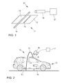
- Figur 2
- eine weitere schematische Darstellung einer Messvorrichtung zum Bewerten von Strukturunterschieden einer reflektierenden Oberfläche;
- Figur 3
- eine Aufnahme eines linienförmigen Reflexbereiches auf der Oberfläche; und
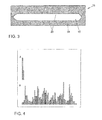
- Figur 4
- zwei Diagramme mit einer Auswertung der Aufnahme.
- FIG. 1
- a schematic representation of a measuring device for evaluating structural differences of a reflective surface;
- FIG. 2
- a further schematic representation of a measuring device for evaluating structural differences of a reflective surface;
- FIG. 3
- a recording of a linear reflex area on the surface; and
- FIG. 4
- two diagrams with an evaluation of the recording.
Auf der Oberfläche 13 erzeugt die Linienförmige Lichtquelle 14 einen linienförmigen Reflexbereich 15. Die Abbildung der linienförmigen Lichtquelle 14 erscheint bei nicht optimaler Oberflächenstruktur des Lackes oder der Oberfläche auf der Oberfläche 13 vereinfacht als Wellenlinie. Diese Wellenlinie wird durch den lokalen Neigungswinkel der Oberfläche 13 hervorgerufen, wodurch helle Felder, hier wird das Licht zum Beobachter reflektiert, und dunkle Felder, hier wird kein oder weniger Licht zum Beobachter reflektiert, entstehen.On the
Dieser Eindruck der hellen und dunklen Felder beziehungsweise des linienförmigen Reflexbereiches 15 wird von einer oder mehreren Kameras 16 aufgenommen. Idealer Weise sind diese Kameras hochauflösend. Die Optik der Kamera 16 ist dabei auf die Oberfläche 13 fokussiert. Bevorzugt sind im Messraum 11 beziehungsweise in der Umgebung des Messraumes 11 geringe störende Streulichteinflüsse vorhanden. Das konzentrierte Licht der Lichtquelle 14 erzeugt einen direkten Lichtreflex 15 auf der Oberfläche 13. Damit ist das vorliegende Verfahren eine Hellfeldmethode.This impression of the light and dark fields or of the line-shaped
Die Kamera 16 beziehungsweise die Kameras 16 sind mit einer Auswertungseinheit 17 verbunden. Die Auswertungseinheit 17 dient zur weiteren Verarbeitung und/oder Bearbeitung der Aufnahmen des Reflexes 15, was im Folgenden weiter beschrieben wird.The
Die Bewertung von Strukturunterschieden der Oberfläche 13 beziehungsweise die Bestimmung der Oberflächenqualität oder Lackqualität orientiert sich an der manuellen Prüfung und ist auf das Erscheinungsbild der Oberfläche 13, wie es ein Kunde wahrnimmt, gerichtet. Damit unterscheidet sich das vorliegende Verfahren von den reinen Fehlererkennungsverfahren, bei denen einzelne Fehlstellen wie Kratzer, Lunker und so weiter detektiert werden sollen. Erfindungsgemäß werden Strukturunterschiede in Mikrometer-Bereich untersucht. Durch die erfindungsgemäße Bewertung der Oberfläche 13, die sich nicht nur auf punktförmige Bereiche, sondern auf linienförmige Reflexbereiche 15 mit einer Länge von wenigen Zentimetern bis zu mehreren Dezimetern reicht, wird vorzugsweise ein linienförmiger Reflexbereich 15 mit einer Länge von 1 - 30 Zentimeter, besonders bevorzugt von 5 - 10 Zentimetern, erfasst und verarbeitet.The evaluation of structural differences of the
Durch diese Vorgehensweise kann bei Lacken auch ein Rückschluss auf Unebenheiten im Basislack, der unter der obersten Lackschicht liegt, getroffen werden. Das vorliegende Verfahren erlaubt somit nicht nur eine reine Betrachtung der Oberfläche 13, sondern auch aller darunter liegenden Schichten, einschließlich des Bleches. So kann auch bei perfekter oberster Lackschicht eine Welligkeit in einer der darunter liegenden Schichten mit diesem Verfahren detektiert werden.With this procedure, it is also possible to draw conclusions regarding unevenness in the basecoat, which is below the uppermost lacquer layer. Thus, the present method allows not only a pure viewing of the
Da das Werkstück 12 über den linienförmigen Reflexbereich 15 gewissermaßen indirekt und berührungslos abgetastet wird, können auch gekrümmte und mehrfach gekrümmte Oberflächen vermessen und bewertet werden. Weiterhin ist es möglich, dass sich das Werkstück 12 beziehungsweise die Messvorrichtung 10 während des Messvorganges bewegen, um so einen höheren Durchsatz beim Messvorgang zu erzielen.Since the
Anhand von
Die lackierten Karossen 12 fahren dabei mit einer konstanten Geschwindigkeit, zum Beispiel einer Bandgeschwindigkeit von 5 Metern pro Minute, an einer oder mehreren linienförmigen Lichtquellen 14 vorbei. Eine oder mehrere Kameras 16, wie zum Beispiel CCD-Kameras, nehmen dabei die Reflexion oder die Reflexionen der Lichtquelle 14 auf den Fahrzeugoberflächen 13 auf und stellen diese Aufnahmen oder Reflektogramme der Auswertungseinheit 17 zur Verfügung. Eine Verbindung zwischen Kamera 16 und der Auswertungseinheit ist beispielhaft dargestellt. Aus Gründen der Übersichtlichkeit sind die anderen Verbindungen zwischen den Kameras 16 und der Auswertungseinheit 17 nicht dargestellt. Die Lichtquellen 14 und die Kameras 16 befinden sich zirka 1 bis 2 Meter vom Messraum 11 beziehungsweise vom Fahrzeug 12 entfernt.The painted
Die Auswertungseinheit 17 kann Teil der Messvorrichtung 10 oder Bestandteil eines Prozesssteuerungssystems sein. Die Bewertung der Lackqualität des Fahrzeugs 12 in Echtzeit durch die Auswertungseinheit 17 erlaubt eine Einbindung dieser Messergebnisse in den Lackierprozess des Kraftfahrzeuges 12. Damit kann ein geschlossener Regelkreis hinsichtlich der Lackqualität des Kraftfahrzeuges 12 erreicht werden.The
Nachdem das Erzeugen des linienförmigen Reflexbereiches 15 auf der Oberfläche 13 und dessen Aufnahme durch mindestens eine Kamera 16 beschrieben worden ist, wird im Folgenden die Auswertung und Bewertung der Oberfläche 13, insbesondere von Strukturunterschieden der Oberfläche 13, im Detail beschrieben.After the generation of the line-shaped
Im Kontrastübergang zwischen dem hellen Reflexbereich 15 und dem dunklen nicht reflektierenden Bereich 19 verläuft jeweils eine Lichtkante 20. Diese Lichtkante 20 ist im Idealfall eine Gerade, wird im Messfall die Form einer Wellenlinie haben.In the contrast transition between the
Nach der Aufnahme des Reflektogramms beziehungsweise der Aufnahme 18 wird zunächst eine Kontrastanpassung der Aufnahme 18 durchgeführt. Anschließend wird mittels einer Objekterkennung die Lichtkante 20 oder die Lichtkanten 20 erkannt. In einer anschließenden Segmentierung der Aufnahme 18 werden die Lichtkanten 20 freigeschnitten und in Bereiche mit einer Kantenlänge von etwa 5 bis 10 Zentimetern unterteilt. Diese Segmentierung erhöht die Robustheit und die Auflösung des Verfahrens.After the recording of the reflectogram or the
Nun wird die extrahierte Lichtkante 20 ausgewertet. Dafür wird eine mathematische Funktion generiert, die auf der Lichtkante 20 der reflektierten Lichtquelle 14 verläuft. Dazu wird eine Fourier-Transformation oder Fast-Fourier-Transformation verwendet. Werden beide Lichtkanten 20 erfasst und verwendet, kann eine Mittelung über die beiden Kanten erfolgen. Die Auswertung der Lichtkante 20 erfolgt dann zum Beispiel über kubische Splines, durch welche eine Näherung beziehungsweise Abbildung der Lichtkante 20 erreicht wird, sowie eine Koeffizientenselektierung zur Transformation in ein Spektrum.Now the extracted
In
Nachdem die linienförmige Lichtkante 20 nunmehr vollständig mathematisch erfasst ist, wird zumindest ein Bereich der Lichtkante 20 mit einer Referenzkante oder Referenzlichtkante verglichen. Die Referenzkante wird durch eine oder mehrere Referenzaufnahmen an einer Glasscheibe, einem Spiegel, einer polierten metallischen Oberfläche und/oder einer lackierten Referenzoberfläche erzeugt. Dabei wird das oben beschrieben mathematische Auswertungsbeziehungsweise Erfassungsverfahren verwendet. Durch den Vergleich beziehungsweise die Korrelation von der Lichtkante 20 mit der Referenzkante wird eine automatisierte Bewertung der Messung vorgenommen.After the line-shaped
In einer Normierungs- oder Kalibrierungsphase wird die Bewertung der Qualität der Lackoberfläche 13 durch Experten vorgenommen und eingestellt. Die Bewertung oder Auswertung der Korrelation beziehungsweise des Korrelationsfaktors führt zu einem Messwert oder einer Qualitätsmaßzahl, der oder die einen Wertebereich zum Beispiel von 0 bis 100 aufweisen kann. Die von Experten vorgenommene Normierung des Wertebereiches kann zum Beispiel derart aussehen, dass eine sehr gute Lackoberfläche oder Qualität eine Maßzahl zwischen 80 und 100 aufweist, eine gute Qualität eine Maßzahl zwischen 50 und 80 aufweist und eine schlechte Qualität eine Maßzahl zwischen 0 und 50 umfasst.In a normalization or calibration phase, the evaluation of the quality of the
Mittels dieser in Echtzeit generierten nummerischen Bewertung der Lackqualität kann ein Mitarbeiter oder ein Prozessleitsystem die Prozessparameter des Lackiervorganges direkt anpassen. Darüber hinaus kann die Qualitätsmaßzahl für eine Dokumentation des Lackierprozesses benutz werden.By means of this real-time generated numerical assessment of the quality of the paint, an employee or a process control system can directly adapt the process parameters of the coating process. In addition, the quality metric can be used to document the painting process.
Während es möglich ist, die Lackbegutachtung nur an bestimmten Bauteilen durchzuführen, wie zum Beispiel der Motorhaube, dem Dach, oder den Türen, ist es vorteilhaft, die gesamte Fahrzeugoberfläche zu begutachten. Weil es hinsichtlich der Benetzung der Oberfläche 13 und den Verlaufseigenschaften des Lackes große Unterschiede zwischen vertikalen und horizontalen Oberflächen 13 geben kann, können durch die gesamte Betrachtung Problemstellen besser identifiziert und berücksichtigt werden.While it is possible to perform paint inspection only on certain components, such as the bonnet, roof, or doors, it is advantageous to inspect the entire vehicle surface. Because there may be large differences between vertical and
- 1010
- Messvorrichtungmeasuring device
- 1111
- Messraummeasuring room
- 1212
- Werkstückworkpiece
- 1313
- Oberflächesurface
- 1414
- Lichtquellelight source
- 1515
- Reflexbereichreflex range
- 1616
- Kameracamera
- 1717
- Auswertungseinheitevaluation unit
- 1818
- Aufnahmeadmission
- 1919
- nicht reflektierender Bereichnon-reflective area
- 2020
- Lichtkantelight edge
Claims (10)
Applications Claiming Priority (1)
| Application Number | Priority Date | Filing Date | Title |
|---|---|---|---|
| DE201310221334 DE102013221334A1 (en) | 2013-10-21 | 2013-10-21 | Method and measuring device for evaluating structural differences of a reflecting surface |
Publications (1)
| Publication Number | Publication Date |
|---|---|
| EP2863168A1 true EP2863168A1 (en) | 2015-04-22 |
Family
ID=51570269
Family Applications (1)
| Application Number | Title | Priority Date | Filing Date |
|---|---|---|---|
| EP20140184706 Withdrawn EP2863168A1 (en) | 2013-10-21 | 2014-09-15 | Method and measuring device for evaluating structural differences of a reflecting surface |
Country Status (3)
| Country | Link |
|---|---|
| EP (1) | EP2863168A1 (en) |
| CN (1) | CN104568966A (en) |
| DE (1) | DE102013221334A1 (en) |
Cited By (1)
| Publication number | Priority date | Publication date | Assignee | Title |
|---|---|---|---|---|
| CN115713532A (en) * | 2023-01-06 | 2023-02-24 | 卡松科技股份有限公司 | Method for detecting pollution of industrial lubricating oil suspension water |
Families Citing this family (2)
| Publication number | Priority date | Publication date | Assignee | Title |
|---|---|---|---|---|
| CN117651668A (en) * | 2021-01-11 | 2024-03-05 | 御眼视觉技术有限公司 | System and method for monitoring the quality of lane markings |
| CN113720854B (en) * | 2021-08-20 | 2023-07-11 | 东风汽车集团股份有限公司 | Appearance detection method for low-glossiness vehicle body paint coating |
Citations (14)
| Publication number | Priority date | Publication date | Assignee | Title |
|---|---|---|---|---|
| US4792232A (en) * | 1987-05-18 | 1988-12-20 | Shell Oil Company | Method and apparatus for detection of undesirable surface deformities |
| US4920385A (en) * | 1984-02-14 | 1990-04-24 | Diffracto Ltd. | Panel surface flaw inspection |
| US5078496A (en) * | 1990-08-14 | 1992-01-07 | Autospect, Inc. | Machine vision surface characterization system |
| US5155558A (en) * | 1990-09-19 | 1992-10-13 | E. I. Du Pont De Nemours And Company | Method and apparatus for analyzing the appearance features of a surface |
| US5414518A (en) * | 1992-08-10 | 1995-05-09 | Chrysler Corporation | Method and apparatus for the evaluation of reflective surfaces |
| US5636024A (en) * | 1994-10-05 | 1997-06-03 | Musco Corporation | Apparatus and method of inspection of specular and semi-specular surfaces |
| DE4123916C2 (en) | 1990-07-19 | 1998-04-09 | Reinhard Malz | Method and device for dynamic detection and classification of surface features and defects of an object |
| JP2000009454A (en) * | 1998-06-25 | 2000-01-14 | Nissan Motor Co Ltd | Apparatus for inspecting surface defect |
| DE69703487T2 (en) | 1997-08-22 | 2001-06-13 | Fraunhofer Ges Forschung | Method and device for automatic inspection of moving surfaces |
| US6266138B1 (en) * | 1999-10-12 | 2001-07-24 | Perceptron, Inc. | System and method for detecting defects in a surface of a workpiece |
| DE10300482B3 (en) * | 2003-01-08 | 2004-07-08 | Uwe Peter Braun | Method and device for detecting surface defects on workpieces with shiny surfaces |
| EP1882896A1 (en) | 2006-07-24 | 2008-01-30 | 3-D Shape GmbH | Method and device for three-dimensional measurement of the shape and local surface perpendiculars of preferably reflective objects |
| DE19726094B4 (en) | 1996-06-25 | 2008-01-31 | Matsushita Electric Works, Ltd., Kadoma | Method for detecting surface defects |
| DE102010060851A1 (en) | 2010-11-29 | 2012-05-31 | Breitmeier Messtechnik Gmbh | Method for evaluation of detected data of image of illuminated surface of work piece by mathematical process, involves conducting structural separation of surface features, particularly surface structures |
Family Cites Families (11)
| Publication number | Priority date | Publication date | Assignee | Title |
|---|---|---|---|---|
| DE3418317C1 (en) * | 1984-05-17 | 1985-01-31 | Daimler-Benz Ag, 7000 Stuttgart | Test chamber for checking the surface of vehicle bodies |
| CH681112A5 (en) * | 1990-01-06 | 1993-01-15 | Wilfried Schoeps | |
| DE4031633A1 (en) * | 1990-10-05 | 1992-04-16 | Sick Optik Elektronik Erwin | OPTICAL INSPECTION DEVICE |
| GB2295224A (en) * | 1994-11-17 | 1996-05-22 | Surface Inspection Ltd | A surface inspection lighting apparatus |
| DE10006663B4 (en) * | 2000-02-15 | 2006-10-05 | Metronom Ag | Method for measuring long-wave surface structures |
| AT408278B (en) * | 2000-03-27 | 2001-10-25 | Theurl Leimholzbau Gmbh | METHOD FOR THE AUTOMATED MONITORING OF THE ADHESIVE APPLICATION ON WOOD AND WOOD MATERIALS |
| DE102004014541B3 (en) * | 2004-03-23 | 2005-05-04 | Koenig & Bauer Ag | Optical system e.g. for banknote checking device, inspection system or flat bed scanner, providing uniform intensity illumination strip on surface of moving material web |
| DE102007024684A1 (en) * | 2007-05-25 | 2008-11-27 | Veselic, Maria | Three-dimensional structure i.e. thin course, detecting method for sheet metal of vehicle body, involves obtaining information about structure from brightness difference of two-dimensional images produced by optical viewing device |
| JP4719284B2 (en) * | 2008-10-10 | 2011-07-06 | トヨタ自動車株式会社 | Surface inspection device |
| EP2492668B1 (en) * | 2011-02-28 | 2013-08-28 | C.R.F. Società Consortile per Azioni | System and method for monitoring painting quality of components, in particular of motor-vehicle bodies |
| DE102011085322A1 (en) * | 2011-10-27 | 2013-05-02 | Siemens Aktiengesellschaft | Apparatus and method for inspecting a specular coating |
-
2013
- 2013-10-21 DE DE201310221334 patent/DE102013221334A1/en not_active Withdrawn
-
2014
- 2014-09-15 EP EP20140184706 patent/EP2863168A1/en not_active Withdrawn
- 2014-10-21 CN CN201410858140.2A patent/CN104568966A/en active Pending
Patent Citations (14)
| Publication number | Priority date | Publication date | Assignee | Title |
|---|---|---|---|---|
| US4920385A (en) * | 1984-02-14 | 1990-04-24 | Diffracto Ltd. | Panel surface flaw inspection |
| US4792232A (en) * | 1987-05-18 | 1988-12-20 | Shell Oil Company | Method and apparatus for detection of undesirable surface deformities |
| DE4123916C2 (en) | 1990-07-19 | 1998-04-09 | Reinhard Malz | Method and device for dynamic detection and classification of surface features and defects of an object |
| US5078496A (en) * | 1990-08-14 | 1992-01-07 | Autospect, Inc. | Machine vision surface characterization system |
| US5155558A (en) * | 1990-09-19 | 1992-10-13 | E. I. Du Pont De Nemours And Company | Method and apparatus for analyzing the appearance features of a surface |
| US5414518A (en) * | 1992-08-10 | 1995-05-09 | Chrysler Corporation | Method and apparatus for the evaluation of reflective surfaces |
| US5636024A (en) * | 1994-10-05 | 1997-06-03 | Musco Corporation | Apparatus and method of inspection of specular and semi-specular surfaces |
| DE19726094B4 (en) | 1996-06-25 | 2008-01-31 | Matsushita Electric Works, Ltd., Kadoma | Method for detecting surface defects |
| DE69703487T2 (en) | 1997-08-22 | 2001-06-13 | Fraunhofer Ges Forschung | Method and device for automatic inspection of moving surfaces |
| JP2000009454A (en) * | 1998-06-25 | 2000-01-14 | Nissan Motor Co Ltd | Apparatus for inspecting surface defect |
| US6266138B1 (en) * | 1999-10-12 | 2001-07-24 | Perceptron, Inc. | System and method for detecting defects in a surface of a workpiece |
| DE10300482B3 (en) * | 2003-01-08 | 2004-07-08 | Uwe Peter Braun | Method and device for detecting surface defects on workpieces with shiny surfaces |
| EP1882896A1 (en) | 2006-07-24 | 2008-01-30 | 3-D Shape GmbH | Method and device for three-dimensional measurement of the shape and local surface perpendiculars of preferably reflective objects |
| DE102010060851A1 (en) | 2010-11-29 | 2012-05-31 | Breitmeier Messtechnik Gmbh | Method for evaluation of detected data of image of illuminated surface of work piece by mathematical process, involves conducting structural separation of surface features, particularly surface structures |
Cited By (1)
| Publication number | Priority date | Publication date | Assignee | Title |
|---|---|---|---|---|
| CN115713532A (en) * | 2023-01-06 | 2023-02-24 | 卡松科技股份有限公司 | Method for detecting pollution of industrial lubricating oil suspension water |
Also Published As
| Publication number | Publication date |
|---|---|
| CN104568966A (en) | 2015-04-29 |
| DE102013221334A1 (en) | 2015-04-23 |
Similar Documents
| Publication | Publication Date | Title |
|---|---|---|
| EP0995108B1 (en) | Method for the automatic recognition of surface defects in body shells and device for carrying out said method | |
| EP3164695B1 (en) | Method and device for determining a material type and/or surface characteristics of a workpiece | |
| DE102013112260B4 (en) | Method and device for detecting defects of deposited semifinished fiber products | |
| EP1716410B1 (en) | Method and system for inspecting surfaces | |
| DE102015221697B3 (en) | Arrangement for determining the surface quality of component surfaces | |
| DE102006037681A1 (en) | Apparatus and method for the topographic determination of surface properties | |
| EP3314036B1 (en) | Method for coating a surface of a metal strip and a metal strip-coating device | |
| DE102009058215A1 (en) | Method for testing surface of bearing component e.g. bearing ring of roller bearing, involves selecting illumination and/or mapping geometry, and determining whether surface defect lies at detection area by analyzing threshold range | |
| EP0598757B1 (en) | Process and device for the quantified evaluation of the physiological impression of reflective surfaces | |
| EP2863168A1 (en) | Method and measuring device for evaluating structural differences of a reflecting surface | |
| DE202018103274U1 (en) | Device for surface inspection of a motor vehicle | |
| AT507121B1 (en) | METHOD OF QUALITY CHECKING OF SURFACES | |
| DE10110994A1 (en) | Device for scanning an object, especially a freshly painted motor vehicle bodywork, has strip light sources and CCD cameras to produce dark and light areas that are used to help determine paint defect size and type | |
| DE10006663B4 (en) | Method for measuring long-wave surface structures | |
| WO2017220452A1 (en) | Laser scanning system | |
| EP3803351A1 (en) | Device for surface inspection of a motor vehicle and method for same | |
| EP3657125B1 (en) | Device and method for determining variations in flatness when handling a material in the form of a strip | |
| EP3525953B1 (en) | Method for working in a forming tool using marking paint | |
| WO2011144374A1 (en) | Method and device for characterising pyramidal surface structures on a substrate | |
| DE102005025291A1 (en) | Method and device for determining surface properties | |
| Bilstein et al. | Two systems for on-line oil film and surface roughness measurement for strip steel production | |
| EP3583382A1 (en) | Method for the non-destructive analysis and classification of a metal workpiece | |
| DE102022128499B3 (en) | Method and device for determining the flatness of a metal strip | |
| EP2463175A2 (en) | Method for locating surface defects | |
| DE102022116099B3 (en) | Surface inspection system and method for detecting surface defects |
Legal Events
| Date | Code | Title | Description |
|---|---|---|---|
| PUAI | Public reference made under article 153(3) epc to a published international application that has entered the european phase |
Free format text: ORIGINAL CODE: 0009012 |
|
| 17P | Request for examination filed |
Effective date: 20140915 |
|
| AK | Designated contracting states |
Kind code of ref document: A1 Designated state(s): AL AT BE BG CH CY CZ DE DK EE ES FI FR GB GR HR HU IE IS IT LI LT LU LV MC MK MT NL NO PL PT RO RS SE SI SK SM TR |
|
| AX | Request for extension of the european patent |
Extension state: BA ME |
|
| R17P | Request for examination filed (corrected) |
Effective date: 20151022 |
|
| RBV | Designated contracting states (corrected) |
Designated state(s): AL AT BE BG CH CY CZ DE DK EE ES FI FR GB GR HR HU IE IS IT LI LT LU LV MC MK MT NL NO PL PT RO RS SE SI SK SM TR |
|
| 17Q | First examination report despatched |
Effective date: 20171213 |
|
| STAA | Information on the status of an ep patent application or granted ep patent |
Free format text: STATUS: THE APPLICATION IS DEEMED TO BE WITHDRAWN |
|
| 18D | Application deemed to be withdrawn |
Effective date: 20180424 |