EP2878321A1 - Needle safety device and drug delivery device - Google Patents
Needle safety device and drug delivery device Download PDFInfo
- Publication number
- EP2878321A1 EP2878321A1 EP13194894.5A EP13194894A EP2878321A1 EP 2878321 A1 EP2878321 A1 EP 2878321A1 EP 13194894 A EP13194894 A EP 13194894A EP 2878321 A1 EP2878321 A1 EP 2878321A1
- Authority
- EP
- European Patent Office
- Prior art keywords
- needle
- inner part
- needle cap
- safety device
- projection
- Prior art date
- Legal status (The legal status is an assumption and is not a legal conclusion. Google has not performed a legal analysis and makes no representation as to the accuracy of the status listed.)
- Ceased
Links
Images

Classifications
-
- A—HUMAN NECESSITIES
- A61—MEDICAL OR VETERINARY SCIENCE; HYGIENE
- A61M—DEVICES FOR INTRODUCING MEDIA INTO, OR ONTO, THE BODY; DEVICES FOR TRANSDUCING BODY MEDIA OR FOR TAKING MEDIA FROM THE BODY; DEVICES FOR PRODUCING OR ENDING SLEEP OR STUPOR
- A61M5/00—Devices for bringing media into the body in a subcutaneous, intra-vascular or intramuscular way; Accessories therefor, e.g. filling or cleaning devices, arm-rests
- A61M5/178—Syringes
- A61M5/31—Details
- A61M5/32—Needles; Details of needles pertaining to their connection with syringe or hub; Accessories for bringing the needle into, or holding the needle on, the body; Devices for protection of needles
- A61M5/3205—Apparatus for removing or disposing of used needles or syringes, e.g. containers; Means for protection against accidental injuries from used needles
- A61M5/321—Means for protection against accidental injuries by used needles
- A61M5/3243—Means for protection against accidental injuries by used needles being axially-extensible, e.g. protective sleeves coaxially slidable on the syringe barrel
- A61M5/3245—Constructional features thereof, e.g. to improve manipulation or functioning
-
- A—HUMAN NECESSITIES
- A61—MEDICAL OR VETERINARY SCIENCE; HYGIENE
- A61M—DEVICES FOR INTRODUCING MEDIA INTO, OR ONTO, THE BODY; DEVICES FOR TRANSDUCING BODY MEDIA OR FOR TAKING MEDIA FROM THE BODY; DEVICES FOR PRODUCING OR ENDING SLEEP OR STUPOR
- A61M5/00—Devices for bringing media into the body in a subcutaneous, intra-vascular or intramuscular way; Accessories therefor, e.g. filling or cleaning devices, arm-rests
- A61M5/178—Syringes
- A61M5/31—Details
- A61M5/32—Needles; Details of needles pertaining to their connection with syringe or hub; Accessories for bringing the needle into, or holding the needle on, the body; Devices for protection of needles
- A61M5/3202—Devices for protection of the needle before use, e.g. caps
- A61M5/3204—Needle cap remover, i.e. devices to dislodge protection cover from needle or needle hub, e.g. deshielding devices
-
- A—HUMAN NECESSITIES
- A61—MEDICAL OR VETERINARY SCIENCE; HYGIENE
- A61M—DEVICES FOR INTRODUCING MEDIA INTO, OR ONTO, THE BODY; DEVICES FOR TRANSDUCING BODY MEDIA OR FOR TAKING MEDIA FROM THE BODY; DEVICES FOR PRODUCING OR ENDING SLEEP OR STUPOR
- A61M5/00—Devices for bringing media into the body in a subcutaneous, intra-vascular or intramuscular way; Accessories therefor, e.g. filling or cleaning devices, arm-rests
- A61M5/178—Syringes
- A61M5/31—Details
- A61M5/32—Needles; Details of needles pertaining to their connection with syringe or hub; Accessories for bringing the needle into, or holding the needle on, the body; Devices for protection of needles
- A61M5/3205—Apparatus for removing or disposing of used needles or syringes, e.g. containers; Means for protection against accidental injuries from used needles
- A61M5/321—Means for protection against accidental injuries by used needles
- A61M5/3243—Means for protection against accidental injuries by used needles being axially-extensible, e.g. protective sleeves coaxially slidable on the syringe barrel
- A61M5/3245—Constructional features thereof, e.g. to improve manipulation or functioning
- A61M2005/3254—Shielding of proximal needles, e.g. for pen needles
Definitions
- the invention relates to a needle safety device and a drug delivery device comprising such a needle safety device.
- the needle of the drug delivery device is covered by a protective needle cap or the so-called rigid needle shield (shortly named RNS).
- the protective needle cap In order to prepare the drug delivery device for delivering a dose the protective needle cap has to be removed from the needle. This may be done by gripping the protective needle cap and pulling it away from the needle. This will usually result in an exposed needle which is undesirable in terms of needle safety. In order to solve that problem the needle of the drug delivery device could be covered by a needle shield or shroud in a manner to hide the needle when the protective needle cap is removed.
- the object is achieved by a needle safety device according to claim 1 and by a drug delivery device according to claim 13.
- a needle safety device for a drug delivery device comprises a needle cap arranged to cover and protect a needle of the drug delivery device and a needle cap remover having an outer part adapted to be arranged to the drug delivery device and an inner part adapted to carry the needle cap.
- the outer part comprises a front end having an opening which at its edge exhibits a projection directed inwards adapted to catch a front projection of the inner part so as to couple the outer part and the inner part.
- the inner part comprises a back end having a grip member adapted to grip a back end of the cap so as to couple the needle cap remover and the cap.
- the term “back” or “proximal” end of a component or of a device refers to the end closest to the user's hand and the term “front” or “distal” end of a component or device refers to the end furthest from the user's hand.
- the multi-part design of the needle cap remover comprising the inner and the outer part which are coupled to each other by corresponding projections allows a limited setting range of the needle cap remover.
- the outer part of the needle cap remover is designed as an outer cap which covers and protects the inner needle shield and thus prevents an early movement of the needle shield.
- the projection of the outer part is formed as at least two opposite arms which ends are angled.
- the ends of the opposite arms could be angled away from each other or otherwise to engage the corresponding front projection of the inner part.
- at least one of the parts, in particular the opposite arms or the front projection are flexible, e.g. are made of a flexible material or soft plastic. Due to a flexible design of the angled ends, the flexible arms of the outer part could be linked to the inner part in such a manner that they are pivoted or swiveled to approach each other so that they are carried over the rigid front projection of the inner part when the outer part is assembled onto or into the inner part.
- the flexible front projection may be pivoted or swiveled away from each other by the rigid arms of the outer part when the outer part is assembled to the inner part, e.g. onto or into the inner part.
- the front projection of the inner part and the projection of the outer part are correspondingly inclined to each other in such a manner that they are coupled to each other to allow a common axial movement after assembling.
- the front projection of the inner part is correspondingly formed to the projection of the outer part.
- the front projection of the inner part is formed as at least two protruding tabs.
- the protruding tabs are protruded from the inner surface of the inner part and are directed inwards in an angle to be gripped by the also angled ends of the arms of the outer part.
- the angled ends of the arms and the angled protruding tabs of the front projection are coupled and engaged by a positive-locking connection and/or form-fitting connection, e.g. snap-fit-connection or latching connection.
- the front projection of the inner part is formed as a dome.
- the dome may be circumferentially formed on the inner surface of the inner part.
- multiple domes e.g. multiple opposite curvatures, may be formed on the inner surface of the inner part.
- the dome is protruded from the inner surface of the inner part and directed inwards and is formed e.g. as an encircling edge with a rounded underside for guiding the projection of the outer part during assembling of the needle safety device.
- the front projection of the inner part is formed as flexible legs or a stem with flexible legs which protrude from the front of the inner part and directed inwards through the opening of the outer part.
- the grip member of the inner part is formed as a back projection of the inner part.
- the back projection bents into the inner part to engage the back end of the needle cap by a positive-locking connection and/or form-fitting connection.
- the back projection is formed as at least two legs directed inwards to engage the back end of the needle cap.
- the grip member of the inner part of the needle cap remover is formed with a profiled surface adapted to grip lateral surfaces of the cap e.g. by friction connection and/or positive-locking connection and/or form-fitting connection.
- the inner surface of the inner part is roughened or lightly ribbed or grooved or coated by a soft coating material.
- the needle cap has an outer surface comprising grip elements adapted to be gripped by the grip member of the inner part of the needle cap remover e.g. by positive-locking connection and/or form-fitting connection and/or friction connection.
- the grip elements of the needle cap may be formed as a profiled outer surface, e.g. as ribs, hooks, domes, grooves and/or protruding pegs, arms, borders or ledges.
- the coupling between the inner part of the needle cap remover and the needle cap is designed in such a manner that after assembling during an axial movement of the needle cap remover the needle cap is removed from the needle together with the needle cap remover.
- the needle cap and the needle cap remover are made from plastic materials with the same or different strengths.
- the needle cap is made of a rigid plastic material to protect the needle against damages.
- the needle cap is also called protective needle shield or rigid needle shield (shortly named RNS).
- the needle cap remover is preferably made of a rigid plastic material, e.g. polypropylene.
- the needle cap may be made from a soft elastomer, for example rubber or a thermoplastic elastomer (TPE), for a tight grip and a good seal between the needle cap and the drug delivery.
- TPE thermoplastic elastomer
- the needle cap remover is rigid and is made from polypropylene for a good protection against needle damages before use and to keep the needle sterile.
- a drug delivery device comprising a needle safety device described above allows an easy assembling of the needle cap remover during manufacturing and a safe removing of the needle cap before use without earlier movement of the needle shield and with a given setting range for the needle cap remover.
- the drug delivery device 2 is a pre-filled syringe 3 having a needle 4.
- the needle 4 may be fixed to the distal end of the syringe 3 or removable therefrom, as a matter of design choice.
- the syringe 3 is hold in a housing 2.1 of the drug delivery device 2.
- the drug delivery device could be an auto-injector or a syringe to be filled.
- the needle safety device 1 comprises a needle cap 5, a needle shield 6 and a needle cap remover 7 which are adapted to be connected to each other by friction connection and/or positive locking connection and/or form-fitting connection.
- the needle shield 6 is being mounted on the housing 2.1 of the drug delivery device 2 in a movable manner and the needle cap 5 is being mounted on the needle 4 in a separable manner.
- the needle cap remover 7 is being mounted on the needle cap 5 in a secured manner and on the drug delivery device 2, in particular on the needle shield 6 in a separable manner.
- the components in particular the needle cap remover 7 with the inner part 8 and the outer part 9 as well as the needle cap 5, have tubular or cylindrical shapes. They may be having different shapes and may have oval or polygonal shapes in cross section.
- the needle cap 5 is arranged to a needle hub 4.1 to cover and protect the needle 4.
- the needle cap 5 may be connected to a needle hub 4.1 of the needle 4 by means of a friction connection and/or positive locking connection.
- the needle cap 5 is preferably of a rigid material and is also called as a protective needle shield or rigid needle shield (shortly named RNS).
- the needle cap is made of a resilient material, especially of a soft elastomer, for example rubber or a thermoplastic elastomer (TPE).
- the needle shield 6 covers and protects the needle 4 before, during and after use.
- the needle shield 6 is movably arranged with respect to the housing 2.1 of the drug delivery device 2.
- the needle shield 6 is provided at the distal or front end of the housing 2.1.
- the needle shield 6 is arranged onto the housing 2.1.
- the needle shield 6 could be arranged into the housing 2.1.
- the needle shield 6 is in the advanced position in which the needle 4 is covered. In this advanced position before use, the needle shield 6 is hold by a positive connection and/or a friction connection and/or a form-fitting connection, e.g. a snap-fit connection. During use, the needle shield 6 is movable from the advanced position to a retracted position (not shown). After use, the needle shield 6 is movable back to the advanced position in which the needle shield 6 is secured with respect to the housing 2.1.
- a positive connection and/or a friction connection and/or a form-fitting connection e.g. a snap-fit connection.
- the needle cap remover 7 comprises at least an outer part 8 and an inner part 9 which are non-releasably coupled to each other after assembling.
- the outer part 8 is adapted to be arranged at the needle shield 6 and is formed as a gripping cap.
- the outer part 8 is releasably coupled to the needle shield 6 by a friction connection and/or a form-fitting connection.
- the inner part 9 is adapted to carry the needle cap 5 by a friction connection and/or a positive locking connection and forms a so-called RNS remover of the needle safety device 1 because the inner part 9 is coupled to the needle cap 5 in such a secured manner that if the inner part 9 is axially moved away from the drug delivery device 2 it takes the needle cap 5 with.
- the needle cap 5 is removed from the needle 4 when the outer part 8 is removed from the drug delivery device 1.
- the outer part 8 comprises a front end 10 having an opening 11 which at its edge exhibits a projection 12 directed inwards.
- the inwardly directed projection 12 is adapted to catch a front projection 13 of the inner part 9 so as to couple the outer part 8 to the inner part 9.
- the inner part 9 which forms the rigid needle shield comprises a back end 14.
- the back end 14 has a grip member 15 adapted to grip a back end 16 of the needle cap 5 so as to couple the needle cap remover 2 to the needle cap 5.
- the grip member 15 is designed as a back projection directed inwards into the inner part 9.
- the back projection bents into the inner part in such a manner that the end of the back projection engages the back end 16 of the needle cap 5 by a positive-locking connection and/or form-fitting connection.
- the back projection is formed as at least two legs 15.1, 15.2 directed inwards to engage the back end 16 of the needle cap 5.
- the multi-part design of the needle cap remover 2 with the inner and outer parts 8 and 9 which are coupled to each other by corresponding projections 12, 13 allows a limited setting range of the needle cap remover 7.
- the outer part 8 of the needle cap remover 7 is designed as an outer cap which covers and protects the inner needle shield 6 and thus prevents an early movement of the needle shield 6.
- the projection 12 of the outer part 8 is designed as at least two opposite arms 12.1, 12.2 which free ends are angled.
- the ends of the opposite arms 12.1, 12.2 are angled away from each other to engage the corresponding front projection 13 of the inner part 9.
- the opposite arms 12.1, 12.2 of the outer part are flexible, e.g. are made of a flexible or soft plastic material.
- the opposite arms 12.1, 12.2 are rigid and the front projection 13 is made of a flexible material.
- the flexible arms 12.1, 12.2 could be pivoted or swiveled to approach each other and thus come closer on to another so that they are carried over the rigid front projection 13 of the inner part 9 when the outer part 8 is assembled to the inner part 9.
- the flexible front projection 13 may be pivoted or swiveled away from each other by the rigid arms 12.1, 12.2 of the rigid outer part 8 when the outer part 8 is assembled to the inner part 9.
- the front projection 13 of the inner part 9 and the projection 12 of the outer part 8 are correspondingly inclined to each other in such a manner that they are coupled to each other to allow a common axial movement.
- the front projection 13 of the inner part 9 is correspondingly formed to the projection 12 of the outer part 8.
- the front projection 13 is formed as at least two protruding tabs 13.1, 13.2.
- the protruding tabs 13.1, 13.2 are protruded from the inner surface of the inner part 9 and are directed inwards in an angle to be gripped by the also angled ends of the arms 12.1, 12.2 of the outer part 8.
- the angled ends of the arms 12.1, 12.2 and the angled protruding tabs 13.1, 13.2 are coupled and securely engaged, wherein the tabs 13.1, 13.2 define a stop on which the arms 12.1, 12.2 come in abutment in such a manner that when the outer part 8 is griped and removed from the needle shield 6 the inner part 9 moves too to remove the needle cap 5 from the needle 4.
- the arms 12.1, 12.2 and the protruding tabs 13.1, 13.2 are securely engaged by a positive-locking connection and/or form-fitting connection, e.g. snap-fit-connection or latching connection.
- the protruding tabs 13.1, 13.2 as well as the grip member 15 of the inner part 9 are disposed in openings of the inner part 9 enabling at least the tabs 13.1, 13.2 to be slightly pivoted or swiveled with regard to the inner part 9 as well as the outer part 8 or needle cap 5 during assembling or removing.
- Figure 2 shows a further embodiment of the invention.
- the invention differs in the kind of the front projection 13 of the inner part 9.
- the front projection 13 is designed as a dome 13.3.
- the dome 13.3 may be formed as circumferential edge on the inner surface of the inner part 9.
- multiple domes may be formed on the inner surface of the inner part (not shown).
- the dome 13.3 is protruded from the inner surface of the inner part 9 and directed to the inside of the tubular inner part 9 towards the angled ends of the arms 12.1, 12.2.
- the underside of the dome 13.3 is rounded to support the guiding of the projection 12 of the outer part 8 during assembling.
- the topside of the dome 13.3 is planar to provide a stop surface for the angled ends of the arms 12.1, 12.2.
- FIG 3 shows yet a further embodiment.
- the invention according to this embodiment also differs in the kind of the front projection 13 of the inner part 9.
- the front projection 13 of the inner part 9 is formed as a stem 13.4 with flexible legs 13.5.
- the flexible legs 13.5 protrude from the front or distal end of the inner part 9 into the distal direction and direct inwards through the opening 11 of the outer part 8.
- the free ends of the flexible legs 13.5 comprise hooks 13.5.1 which cooperate with complementary angled ends of the arms 12.1, 12.2 of the outer part 8.
- the hooks 13.5.1 are engaged with the angled ends of the arms 12.1, 12.2 and the inner part 9 as well as the needle cap 5 are removed too from the drug delivery device 2.
- FIG. 4 shows another embodiment of the invention.
- the invention according to this embodiment differs in the kind of the grip member 15 of the inner part 9.
- the grip member 15 of the inner part 9 is formed with a profiled surface adapted to grip lateral surfaces of the needle cap 5 e.g. by friction connection and/or positive-locking connection and/or form-fitting connection.
- the inner surface of the inner part 9 may be roughened or lightly ribbed or grooved or coated with a coating material so that the inner surface is softened.
- the needle cap 5 has grip elements 5.1 on the outer surface.
- the grip elements 5.1 are adapted to be gripped by the grip member 15 of the inner part 9 e.g. by positive-locking connection and/or form-fitting connection and/or friction connection. As shown in figure 4 , the grip elements 5.1 are formed as hooks.
- the grip elements 5.1 may be formed as a profiled outer surface, e.g. as ribs, domes, grooves and/or protruding pegs, arms.
- the coupling between the inner part 9 and the needle cap 5 is designed in such a manner that after assembling during an axial movement of the needle cap remover 7 the needle cap 5 is removed from the needle 4 together with the needle cap remover 7 and thus with the inner and outer parts 9, 8.
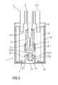
- Figures 5 and 6 show further embodiments with possible combinations of different couplings of the inner part 9 and the outer part 8 as well as the different couplings of the inner part 9 and the needle cap 5.
- drug or “medicament”, as used herein, means a pharmaceutical formulation containing at least one pharmaceutically active compound, wherein in one embodiment the pharmaceutically active compound has a molecular weight up to 1500 Da and/or is a peptide, a proteine, a polysaccharide, a vaccine, a DNA, a RNA, an enzyme, an antibody or a fragment thereof, a hormone or an oligonucleotide, or a mixture of the above-mentioned pharmaceutically active compound, wherein in a further embodiment the pharmaceutically active compound is useful for the treatment and/or prophylaxis of diabetes mellitus or complications associated with diabetes mellitus such as diabetic retinopathy, thromboembolism disorders such as deep vein or pulmonary thromboembolism, acute coronary syndrome (ACS), angina, myocardial infarction, cancer, macular degeneration, inflammation, hay fever, atherosclerosis and/or rheumatoid arthritis, wherein in a further
- Insulin analogues are for example Gly(A21), Arg(B31), Arg(B32) human insulin; Lys(B3), Glu(B29) human insulin; Lys(B28), Pro(B29) human insulin; Asp(B28) human insulin; human insulin, wherein proline in position B28 is replaced by Asp, Lys, Leu, Val or Ala and wherein in position B29 Lys may be replaced by Pro; Ala(B26) human insulin; Des(B28-B30) human insulin; Des(B27) human insulin and Des(B30) human insulin.
- Insulin derivates are for example B29-N-myristoyl-des(B30) human insulin; B29-N-palmitoyl-des(B30) human insulin; B29-N-myristoyl human insulin; B29-N-palmitoyl human insulin; B28-N-myristoyl LysB28ProB29 human insulin; B28-N-palmitoyl-LysB28ProB29 human insulin; B30-N-myristoyl-ThrB29LysB30 human insulin; B30-N-palmitoyl- ThrB29LysB30 human insulin; B29-N-(N-palmitoyl-Y-glutamyl)-des(B30) human insulin; B29-N-(N-lithocholyl-Y-glutamyl)-des(B30) human insulin; B29-N-( ⁇ -carboxyheptadecanoyl)-des(B30) human insulin and B29-N-( ⁇ -carbox
- Exendin-4 for example means Exendin-4(1-39), a peptide of the sequence H-His-Gly-Glu-Gly-Thr-Phe-Thr-Ser-Asp-Leu-Ser-Lys-Gln-Met-Glu-Glu-Glu-Ala-Val-Arg-Leu-Phe-Ile-Glu-Trp-Leu-Lys-Asn-Gly-Gly-Pro-Ser-Ser-Gly-Ala-Pro-Pro-Pro-Ser-NH2.
- Exendin-4 derivatives are for example selected from the following list of compounds:
- Hormones are for example hypophysis hormones or hypothalamus hormones or regulatory active peptides and their antagonists as listed in Rote Liste, ed. 2008, Chapter 50, such as Gonadotropine (Follitropin, Lutropin, Choriongonadotropin, Menotropin), Somatropine (Somatropin), Desmopressin, Terlipressin, Gonadorelin, Triptorelin, Leuprorelin, Buserelin, Nafarelin, Goserelin.
- Gonadotropine Follitropin, Lutropin, Choriongonadotropin, Menotropin
- Somatropine Somatropin
- Desmopressin Terlipressin
- Gonadorelin Triptorelin
- Leuprorelin Buserelin
- Nafarelin Goserelin.
- a polysaccharide is for example a glucosaminoglycane, a hyaluronic acid, a heparin, a low molecular weight heparin or an ultra low molecular weight heparin or a derivative thereof, or a sulphated, e.g. a poly-sulphated form of the above-mentioned polysaccharides, and/or a pharmaceutically acceptable salt thereof.
- An example of a pharmaceutically acceptable salt of a poly-sulphated low molecular weight heparin is enoxaparin sodium.
- Antibodies are globular plasma proteins ( ⁇ 150 kD) that are also known as immunoglobulins which share a basic structure. As they have sugar chains added to amino acid residues, they are glycoproteins.
- the basic functional unit of each antibody is an immunoglobulin (1g) monomer (containing only one Ig unit); secreted antibodies can also be dimeric with two Ig units as with IgA, tetrameric with four Ig units like teleost fish IgM, or pentameric with five Ig units, like mammalian IgM.
- the Ig monomer is a "Y"-shaped molecule that consists of four polypeptide chains; two identical heavy chains and two identical light chains connected by disulfide bonds between cysteine residues. Each heavy chain is about 440 amino acids long; each light chain is about 220 amino acids long. Heavy and light chains each contain intrachain disulfide bonds which stabilize their folding. Each chain is composed of structural domains called Ig domains. These domains contain about 70-110 amino acids and are classified into different categories (for example, variable or V, and constant or C) according to their size and function. They have a characteristic immunoglobulin fold in which two ⁇ sheets create a "sandwich" shape, held together by interactions between conserved cysteines and other charged amino acids.
- Ig heavy chain There are five types of mammalian Ig heavy chain denoted by ⁇ , ⁇ , ⁇ , ⁇ , and ⁇ .
- the type of heavy chain present defines the isotype of antibody; these chains are found in IgA, IgD, IgE, IgG, and IgM antibodies, respectively.
- Distinct heavy chains differ in size and composition; ⁇ and ⁇ contain approximately 450 amino acids and ⁇ approximately 500 amino acids, while ⁇ and ⁇ have approximately 550 amino acids.
- Each heavy chain has two regions, the constant region (C H ) and the variable region (V H ).
- the constant region is essentially identical in all antibodies of the same isotype, but differs in antibodies of different isotypes.
- Heavy chains ⁇ , ⁇ and ⁇ have a constant region composed of three tandem Ig domains, and a hinge region for added flexibility; heavy chains ⁇ and ⁇ have a constant region composed of four immunoglobulin domains.
- the variable region of the heavy chain differs in antibodies produced by different B cells, but is the same for all antibodies produced by a single B cell or B cell clone.
- the variable region of each heavy chain is approximately 110 amino acids long and is composed of a single Ig domain.
- a light chain has two successive domains: one constant domain (CL) and one variable domain (VL).
- CL constant domain
- VL variable domain
- the approximate length of a light chain is 211 to 217 amino acids.
- Each antibody contains two light chains that are always identical; only one type of light chain, ⁇ or ⁇ , is present per antibody in mammals.
- variable (V) regions are responsible for binding to the antigen, i.e. for its antigen specificity.
- VL variable light
- VH variable heavy chain
- CDRs Complementarity Determining Regions
- an "antibody fragment” contains at least one antigen binding fragment as defined above, and exhibits essentially the same function and specificity as the complete antibody of which the fragment is derived from.
- Limited proteolytic digestion with papain cleaves the Ig prototype into three fragments. Two identical amino terminal fragments, each containing one entire L chain and about half an H chain, are the antigen binding fragments (Fab).
- the Fc contains carbohydrates, complement-binding, and FcR-binding sites.
- F(ab')2 is divalent for antigen binding.
- the disulfide bond of F(ab')2 may be cleaved in order to obtain Fab'.
- the variable regions of the heavy and light chains can be fused together to form a single chain variable fragment (scFv).
- Pharmaceutically acceptable salts are for example acid addition salts and basic salts.
- Acid addition salts are e.g. HCl or HBr salts.
- Basic salts are e.g. salts having a cation selected from alkali or alkaline, e.g. Na+, or K+, or Ca2+, or an ammonium ion N+(R1)(R2)(R3)(R4), wherein R1 to R4 independently of each other mean: hydrogen, an optionally substituted C1-C6-alkyl group, an optionally substituted C2-C6-alkenyl group, an optionally substituted C6-C10-aryl group, or an optionally substituted C6-C10-heteroaryl group.
- solvates are for example hydrates.
Abstract
The invention refers to a needle safety device (1) comprising a needle cap (5) arranged to cover and protect a needle (4), a needle shield (6) relatively movable with respect to a drug delivery device (2) to cover and protect the needle (4) and a needle cap remover (7). The needle cap remover (7) has an outer part (8) adapted to be arranged to the needle shield (6) and an inner part (9) adapted to carry the needle cap (5), wherein the outer part (8) comprises a front end (10) having an opening (11) which at its edge exhibits a projection (12) directed inwards adapted to catch a front projection (13) of the inner part (9) and the inner part (9) comprises a back end (14) having a grip member (15) adapted to grip a back end (16) of the needle cap (5).
Description
- The invention relates to a needle safety device and a drug delivery device comprising such a needle safety device.
- Many drug delivery devices of the prior art, such as auto-injectors, syringes, have been developed for self-administration of the drug.
- To protect the needle of the drug delivery device from damage or to protect people from needle-prick injuries before using of the device, the needle of the drug delivery device is covered by a protective needle cap or the so-called rigid needle shield (shortly named RNS).
- In order to prepare the drug delivery device for delivering a dose the protective needle cap has to be removed from the needle. This may be done by gripping the protective needle cap and pulling it away from the needle. This will usually result in an exposed needle which is undesirable in terms of needle safety. In order to solve that problem the needle of the drug delivery device could be covered by a needle shield or shroud in a manner to hide the needle when the protective needle cap is removed.
- It is an object of the present invention to provide a needle safety device that reduces the risk of needle-prick injuries and needle damages in particular before using the device and which is simple to use and manufacture.
- The object is achieved by a needle safety device according to
claim 1 and by a drug delivery device according toclaim 13. - Preferred embodiments of the invention are given in the dependent claims.
- According to the invention, a needle safety device for a drug delivery device comprises a needle cap arranged to cover and protect a needle of the drug delivery device and a needle cap remover having an outer part adapted to be arranged to the drug delivery device and an inner part adapted to carry the needle cap. The outer part comprises a front end having an opening which at its edge exhibits a projection directed inwards adapted to catch a front projection of the inner part so as to couple the outer part and the inner part. The inner part comprises a back end having a grip member adapted to grip a back end of the cap so as to couple the needle cap remover and the cap.
- In the context of this specification, the term "back" or "proximal" end of a component or of a device refers to the end closest to the user's hand and the term "front" or "distal" end of a component or device refers to the end furthest from the user's hand.
- The multi-part design of the needle cap remover comprising the inner and the outer part which are coupled to each other by corresponding projections allows a limited setting range of the needle cap remover. In a possible embodiment, the outer part of the needle cap remover is designed as an outer cap which covers and protects the inner needle shield and thus prevents an early movement of the needle shield.
- In an exemplary embodiment, the projection of the outer part is formed as at least two opposite arms which ends are angled. In particular, the ends of the opposite arms could be angled away from each other or otherwise to engage the corresponding front projection of the inner part. Depending on the material of the inner and outer part of the needle cap remover, at least one of the parts, in particular the opposite arms or the front projection are flexible, e.g. are made of a flexible material or soft plastic. Due to a flexible design of the angled ends, the flexible arms of the outer part could be linked to the inner part in such a manner that they are pivoted or swiveled to approach each other so that they are carried over the rigid front projection of the inner part when the outer part is assembled onto or into the inner part. Otherwise, the flexible front projection may be pivoted or swiveled away from each other by the rigid arms of the outer part when the outer part is assembled to the inner part, e.g. onto or into the inner part. After assembling of the outer and inner parts, the front projection of the inner part and the projection of the outer part are correspondingly inclined to each other in such a manner that they are coupled to each other to allow a common axial movement after assembling.
- In a possible embodiment, the front projection of the inner part is correspondingly formed to the projection of the outer part. In particular the front projection of the inner part is formed as at least two protruding tabs. The protruding tabs are protruded from the inner surface of the inner part and are directed inwards in an angle to be gripped by the also angled ends of the arms of the outer part. During assembling of the outer part onto or into the inner part, the angled ends of the arms and the angled protruding tabs of the front projection are coupled and engaged by a positive-locking connection and/or form-fitting connection, e.g. snap-fit-connection or latching connection.
- According to a further embodiment, the front projection of the inner part is formed as a dome. The dome may be circumferentially formed on the inner surface of the inner part. Alternatively, multiple domes, e.g. multiple opposite curvatures, may be formed on the inner surface of the inner part. In other words, the dome is protruded from the inner surface of the inner part and directed inwards and is formed e.g. as an encircling edge with a rounded underside for guiding the projection of the outer part during assembling of the needle safety device.
- In yet a further embodiment, the front projection of the inner part is formed as flexible legs or a stem with flexible legs which protrude from the front of the inner part and directed inwards through the opening of the outer part.
- According to another embodiment of the invention, the grip member of the inner part is formed as a back projection of the inner part. The back projection bents into the inner part to engage the back end of the needle cap by a positive-locking connection and/or form-fitting connection. In particular, the back projection is formed as at least two legs directed inwards to engage the back end of the needle cap.
- According to an alternative embodiment, the grip member of the inner part of the needle cap remover is formed with a profiled surface adapted to grip lateral surfaces of the cap e.g. by friction connection and/or positive-locking connection and/or form-fitting connection. In particular, the inner surface of the inner part is roughened or lightly ribbed or grooved or coated by a soft coating material.
- Alternatively or additionally, the needle cap has an outer surface comprising grip elements adapted to be gripped by the grip member of the inner part of the needle cap remover e.g. by positive-locking connection and/or form-fitting connection and/or friction connection. In particular, the grip elements of the needle cap may be formed as a profiled outer surface, e.g. as ribs, hooks, domes, grooves and/or protruding pegs, arms, borders or ledges. The coupling between the inner part of the needle cap remover and the needle cap is designed in such a manner that after assembling during an axial movement of the needle cap remover the needle cap is removed from the needle together with the needle cap remover.
- According to another embodiment of the invention, the needle cap and the needle cap remover are made from plastic materials with the same or different strengths. In particular, the needle cap is made of a rigid plastic material to protect the needle against damages. The needle cap is also called protective needle shield or rigid needle shield (shortly named RNS). The needle cap remover is preferably made of a rigid plastic material, e.g. polypropylene. Alternatively, the needle cap may be made from a soft elastomer, for example rubber or a thermoplastic elastomer (TPE), for a tight grip and a good seal between the needle cap and the drug delivery. The needle cap remover is rigid and is made from polypropylene for a good protection against needle damages before use and to keep the needle sterile.
- According to the invention, a drug delivery device comprising a needle safety device described above allows an easy assembling of the needle cap remover during manufacturing and a safe removing of the needle cap before use without earlier movement of the needle shield and with a given setting range for the needle cap remover.
- Further scope of applicability of the present invention will become apparent from the detailed description given hereinafter. However, it should be understood that the detailed description and specific examples, while indicating preferred embodiments of the invention, are given by way of illustration only, since various changes and modifications within the spirit and scope of the invention will become apparent to those skilled in the art from this detailed description.
- The present invention will become more fully understood from the detailed description given herein below and the accompanying drawings which are given by way of illustration only, and thus, are not limitive of the present invention, and wherein:
- Figure 1
- shows a longitudinal section of an exemplary embodiment of a needle safety device for a drug delivery device,
- Figures 2 to 6
- show longitudinal sections of different embodiments of a needle safety device for a drug delivery device.
- Corresponding parts are marked with the same reference symbols in all figures.
-
-
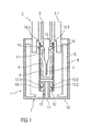
Figure 1 shows one embodiment of the present invention in a longitudinal section of aneedle safety device 1 for adrug delivery device 2. - The
drug delivery device 2 is apre-filled syringe 3 having aneedle 4. Theneedle 4 may be fixed to the distal end of thesyringe 3 or removable therefrom, as a matter of design choice. Thesyringe 3 is hold in a housing 2.1 of thedrug delivery device 2. Alternatively, the drug delivery device could be an auto-injector or a syringe to be filled. - The
needle safety device 1 comprises aneedle cap 5, aneedle shield 6 and aneedle cap remover 7 which are adapted to be connected to each other by friction connection and/or positive locking connection and/or form-fitting connection. As it can be seen, theneedle shield 6 is being mounted on the housing 2.1 of thedrug delivery device 2 in a movable manner and theneedle cap 5 is being mounted on theneedle 4 in a separable manner. Theneedle cap remover 7 is being mounted on theneedle cap 5 in a secured manner and on thedrug delivery device 2, in particular on theneedle shield 6 in a separable manner. - As not shown in the longitudinal sections of the
needle safety device 1, the components, in particular theneedle cap remover 7 with theinner part 8 and theouter part 9 as well as theneedle cap 5, have tubular or cylindrical shapes. They may be having different shapes and may have oval or polygonal shapes in cross section. - In detail, the
needle cap 5 is arranged to a needle hub 4.1 to cover and protect theneedle 4. Theneedle cap 5 may be connected to a needle hub 4.1 of theneedle 4 by means of a friction connection and/or positive locking connection. Theneedle cap 5 is preferably of a rigid material and is also called as a protective needle shield or rigid needle shield (shortly named RNS). Alternatively, the needle cap is made of a resilient material, especially of a soft elastomer, for example rubber or a thermoplastic elastomer (TPE). - The
needle shield 6 covers and protects theneedle 4 before, during and after use. Theneedle shield 6 is movably arranged with respect to the housing 2.1 of thedrug delivery device 2. In the shown embodiment, theneedle shield 6 is provided at the distal or front end of the housing 2.1. In particular, theneedle shield 6 is arranged onto the housing 2.1. Alternatively, theneedle shield 6 could be arranged into the housing 2.1. - As shown in
figure 1 , theneedle shield 6 is in the advanced position in which theneedle 4 is covered. In this advanced position before use, theneedle shield 6 is hold by a positive connection and/or a friction connection and/or a form-fitting connection, e.g. a snap-fit connection. During use, theneedle shield 6 is movable from the advanced position to a retracted position (not shown). After use, theneedle shield 6 is movable back to the advanced position in which theneedle shield 6 is secured with respect to the housing 2.1. - The
needle cap remover 7 comprises at least anouter part 8 and aninner part 9 which are non-releasably coupled to each other after assembling. Theouter part 8 is adapted to be arranged at theneedle shield 6 and is formed as a gripping cap. Preferably, theouter part 8 is releasably coupled to theneedle shield 6 by a friction connection and/or a form-fitting connection. - The
inner part 9 is adapted to carry theneedle cap 5 by a friction connection and/or a positive locking connection and forms a so-called RNS remover of theneedle safety device 1 because theinner part 9 is coupled to theneedle cap 5 in such a secured manner that if theinner part 9 is axially moved away from thedrug delivery device 2 it takes theneedle cap 5 with. - Due to the coupling of the
outer part 8 with theinner part 9 and theinner part 9 with theneedle cap 5, theneedle cap 5 is removed from theneedle 4 when theouter part 8 is removed from thedrug delivery device 1. - The
outer part 8 comprises afront end 10 having anopening 11 which at its edge exhibits aprojection 12 directed inwards. - The inwardly directed
projection 12 is adapted to catch afront projection 13 of theinner part 9 so as to couple theouter part 8 to theinner part 9. Theinner part 9 which forms the rigid needle shield comprises aback end 14. Theback end 14 has agrip member 15 adapted to grip aback end 16 of theneedle cap 5 so as to couple theneedle cap remover 2 to theneedle cap 5. - The
grip member 15 is designed as a back projection directed inwards into theinner part 9. The back projection bents into the inner part in such a manner that the end of the back projection engages theback end 16 of theneedle cap 5 by a positive-locking connection and/or form-fitting connection. In particular, the back projection is formed as at least two legs 15.1, 15.2 directed inwards to engage theback end 16 of theneedle cap 5. - The multi-part design of the
needle cap remover 2 with the inner andouter parts projections needle cap remover 7. In a possible embodiment theouter part 8 of theneedle cap remover 7 is designed as an outer cap which covers and protects theinner needle shield 6 and thus prevents an early movement of theneedle shield 6. - In an exemplary embodiment, the
projection 12 of theouter part 8 is designed as at least two opposite arms 12.1, 12.2 which free ends are angled. In particular, the ends of the opposite arms 12.1, 12.2 are angled away from each other to engage the correspondingfront projection 13 of theinner part 9. Depending on the material of the inner andouter part needle cap remover 7, at least one of the parts, in particular the opposite arms 12.1, 12.2 of the outer part are flexible, e.g. are made of a flexible or soft plastic material. Alternatively, the opposite arms 12.1, 12.2 are rigid and thefront projection 13 is made of a flexible material. - Due to the flexible design of the arms 12.1, 12.2 with the angled ends, the flexible arms 12.1, 12.2 could be pivoted or swiveled to approach each other and thus come closer on to another so that they are carried over the
rigid front projection 13 of theinner part 9 when theouter part 8 is assembled to theinner part 9. - Otherwise, the
flexible front projection 13 may be pivoted or swiveled away from each other by the rigid arms 12.1, 12.2 of the rigidouter part 8 when theouter part 8 is assembled to theinner part 9. After assembling of the outer andinner part front projection 13 of theinner part 9 and theprojection 12 of theouter part 8 are correspondingly inclined to each other in such a manner that they are coupled to each other to allow a common axial movement. - As it is shown in
figure 1 , thefront projection 13 of theinner part 9 is correspondingly formed to theprojection 12 of theouter part 8. In particular thefront projection 13 is formed as at least two protruding tabs 13.1, 13.2. The protruding tabs 13.1, 13.2 are protruded from the inner surface of theinner part 9 and are directed inwards in an angle to be gripped by the also angled ends of the arms 12.1, 12.2 of theouter part 8. - After assembling of
needle cap remover 7, the angled ends of the arms 12.1, 12.2 and the angled protruding tabs 13.1, 13.2 are coupled and securely engaged, wherein the tabs 13.1, 13.2 define a stop on which the arms 12.1, 12.2 come in abutment in such a manner that when theouter part 8 is griped and removed from theneedle shield 6 theinner part 9 moves too to remove theneedle cap 5 from theneedle 4. In particular, the arms 12.1, 12.2 and the protruding tabs 13.1, 13.2 are securely engaged by a positive-locking connection and/or form-fitting connection, e.g. snap-fit-connection or latching connection. - The protruding tabs 13.1, 13.2 as well as the
grip member 15 of theinner part 9 are disposed in openings of theinner part 9 enabling at least the tabs 13.1, 13.2 to be slightly pivoted or swiveled with regard to theinner part 9 as well as theouter part 8 orneedle cap 5 during assembling or removing. -
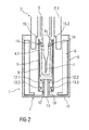
Figure 2 shows a further embodiment of the invention. The invention differs in the kind of thefront projection 13 of theinner part 9. Thefront projection 13 is designed as a dome 13.3. The dome 13.3 may be formed as circumferential edge on the inner surface of theinner part 9. - Alternatively, multiple domes, e.g. multiple opposite curvatures, may be formed on the inner surface of the inner part (not shown). In other words, the dome 13.3 is protruded from the inner surface of the
inner part 9 and directed to the inside of the tubularinner part 9 towards the angled ends of the arms 12.1, 12.2. - The underside of the dome 13.3 is rounded to support the guiding of the
projection 12 of theouter part 8 during assembling. The topside of the dome 13.3 is planar to provide a stop surface for the angled ends of the arms 12.1, 12.2. -
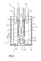
Figure 3 shows yet a further embodiment. The invention according to this embodiment also differs in the kind of thefront projection 13 of theinner part 9. Thefront projection 13 of theinner part 9 is formed as a stem 13.4 with flexible legs 13.5. The flexible legs 13.5 protrude from the front or distal end of theinner part 9 into the distal direction and direct inwards through theopening 11 of theouter part 8. - The free ends of the flexible legs 13.5 comprise hooks 13.5.1 which cooperate with complementary angled ends of the arms 12.1, 12.2 of the
outer part 8. When theouter part 8 is griped and removed from theneedle shield 6 to remove theneedle cap 5 from theneedle 4, the hooks 13.5.1 are engaged with the angled ends of the arms 12.1, 12.2 and theinner part 9 as well as theneedle cap 5 are removed too from thedrug delivery device 2. -
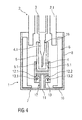
Figure 4 shows another embodiment of the invention. The invention according to this embodiment differs in the kind of thegrip member 15 of theinner part 9. - The
grip member 15 of theinner part 9 is formed with a profiled surface adapted to grip lateral surfaces of theneedle cap 5 e.g. by friction connection and/or positive-locking connection and/or form-fitting connection. In particular, the inner surface of theinner part 9 may be roughened or lightly ribbed or grooved or coated with a coating material so that the inner surface is softened. - Additionally, the
needle cap 5 has grip elements 5.1 on the outer surface. The grip elements 5.1 are adapted to be gripped by thegrip member 15 of theinner part 9 e.g. by positive-locking connection and/or form-fitting connection and/or friction connection. As shown infigure 4 , the grip elements 5.1 are formed as hooks. - Alternatively, the grip elements 5.1 may be formed as a profiled outer surface, e.g. as ribs, domes, grooves and/or protruding pegs, arms. The coupling between the
inner part 9 and theneedle cap 5 is designed in such a manner that after assembling during an axial movement of theneedle cap remover 7 theneedle cap 5 is removed from theneedle 4 together with theneedle cap remover 7 and thus with the inner andouter parts -
Figures 5 and6 show further embodiments with possible combinations of different couplings of theinner part 9 and theouter part 8 as well as the different couplings of theinner part 9 and theneedle cap 5. - The term "drug" or "medicament", as used herein, means a pharmaceutical formulation containing at least one pharmaceutically active compound,
wherein in one embodiment the pharmaceutically active compound has a molecular weight up to 1500 Da and/or is a peptide, a proteine, a polysaccharide, a vaccine, a DNA, a RNA, an enzyme, an antibody or a fragment thereof, a hormone or an oligonucleotide, or a mixture of the above-mentioned pharmaceutically active compound,
wherein in a further embodiment the pharmaceutically active compound is useful for the treatment and/or prophylaxis of diabetes mellitus or complications associated with diabetes mellitus such as diabetic retinopathy, thromboembolism disorders such as deep vein or pulmonary thromboembolism, acute coronary syndrome (ACS), angina, myocardial infarction, cancer, macular degeneration, inflammation, hay fever, atherosclerosis and/or rheumatoid arthritis,
wherein in a further embodiment the pharmaceutically active compound comprises at least one peptide for the treatment and/or prophylaxis of diabetes mellitus or complications associated with diabetes mellitus such as diabetic retinopathy,
wherein in a further embodiment the pharmaceutically active compound comprises at least one human insulin or a human insulin analogue or derivative, glucagon-like peptide (GLP-1) or an analogue or derivative thereof, or exendin-3 or exendin-4 or an analogue or derivative of exendin-3 or exendin-4. - Insulin analogues are for example Gly(A21), Arg(B31), Arg(B32) human insulin; Lys(B3), Glu(B29) human insulin; Lys(B28), Pro(B29) human insulin; Asp(B28) human insulin; human insulin, wherein proline in position B28 is replaced by Asp, Lys, Leu, Val or Ala and wherein in position B29 Lys may be replaced by Pro; Ala(B26) human insulin; Des(B28-B30) human insulin; Des(B27) human insulin and Des(B30) human insulin.
- Insulin derivates are for example B29-N-myristoyl-des(B30) human insulin; B29-N-palmitoyl-des(B30) human insulin; B29-N-myristoyl human insulin; B29-N-palmitoyl human insulin; B28-N-myristoyl LysB28ProB29 human insulin; B28-N-palmitoyl-LysB28ProB29 human insulin; B30-N-myristoyl-ThrB29LysB30 human insulin; B30-N-palmitoyl- ThrB29LysB30 human insulin; B29-N-(N-palmitoyl-Y-glutamyl)-des(B30) human insulin; B29-N-(N-lithocholyl-Y-glutamyl)-des(B30) human insulin; B29-N-(ω-carboxyheptadecanoyl)-des(B30) human insulin and B29-N-(ω-carboxyheptadecanoyl) human insulin.
- Exendin-4 for example means Exendin-4(1-39), a peptide of the sequence H-His-Gly-Glu-Gly-Thr-Phe-Thr-Ser-Asp-Leu-Ser-Lys-Gln-Met-Glu-Glu-Glu-Ala-Val-Arg-Leu-Phe-Ile-Glu-Trp-Leu-Lys-Asn-Gly-Gly-Pro-Ser-Ser-Gly-Ala-Pro-Pro-Pro-Ser-NH2.
- Exendin-4 derivatives are for example selected from the following list of compounds:
- H-(Lys)4-des Pro36, des Pro37 Exendin-4(1-39)-NH2,
- H-(Lys)5-des Pro36, des Pro37 Exendin-4(1-39)-NH2,
- des Pro36 Exendin-4(1-39),
- des Pro36 [Asp28] Exendin-4(1-39),
- des Pro36 [IsoAsp28] Exendin-4(1-39),
- des Pro36 [Met(O)14, Asp28] Exendin-4(1-39),
- des Pro36 [Met(O)14, IsoAsp28] Exendin-4(1-39),
- des Pro36 [Trp(02)25, Asp28] Exendin-4(1-39),
- des Pro36 [Trp(02)25, IsoAsp28] Exendin-4(1-39),
- des Pro36 [Met(O)14 Trp(02)25, Asp28] Exendin-4(1-39),
- des Pro36 [Met(O)14 Trp(02)25, IsoAsp28] Exendin-4(1-39); or
- des Pro36 [Asp28] Exendin-4(1-39),
- des Pro36 [IsoAsp28] Exendin-4(1-39),
- des Pro36 [Met(O)14, Asp28] Exendin-4(1-39),
- des Pro36 [Met(O)14, IsoAsp28] Exendin-4(1-39),
- des Pro36 [Trp(02)25, Asp28] Exendin-4(1-39),
- des Pro36 [Trp(02)25, IsoAsp28] Exendin-4(1-39),
- des Pro36 [Met(O)14 Trp(02)25, Asp28] Exendin-4(1-39),
- des Pro36 [Met(O)14 Trp(02)25, IsoAsp28] Exendin-4(1-39),
- des Pro36 Exendin-4(1-39)-Lys6-NH2 (AVE0010),
- H-(Lys)6-des Pro36 [Asp28] Exendin-4(1-39)-Lys6-NH2,
- des Asp28 Pro36, Pro37, Pro38Exendin-4(1-39)-NH2,
- H-(Lys)6-des Pro36, Pro38 [Asp28] Exendin-4(1-39)-NH2,
- H-Asn-(Glu)5des Pro36, Pro37, Pro38 [Asp28] Exendin-4(1-39)-NH2,
- des Pro36, Pro37, Pro38 [Asp28] Exendin-4(1-39)-(Lys)6-NH2,
- H-(Lys)6-des Pro36, Pro37, Pro38 [Asp28] Exendin-4(1-39)-(Lys)6-NH2,
- H-Asn-(Glu)5-des Pro36, Pro37, Pro38 [Asp28] Exendin-4(1-39)-(Lys)6-NH2,
- H-(Lys)6-des Pro36 [Trp(02)25, Asp28] Exendin-4(1-39)-Lys6-NH2,
- H-des Asp28 Pro36, Pro37, Pro38 [Trp(02)25] Exendin-4(1-39)-NH2,
- H-(Lys)6-des Pro36, Pro37, Pro38 [Trp(02)25, Asp28] Exendin-4(1-39)-NH2,
- H-Asn-(Glu)5-des Pro36, Pro37, Pro38 [Trp(02)25, Asp28] Exendin-4(1-39)-NH2,
- des Pro36, Pro37, Pro38 [Trp(02)25, Asp28] Exendin-4(1-39)-(Lys)6-NH2,
- H-(Lys)6-des Pro36, Pro37, Pro38 [Trp(02)25, Asp28] Exendin-4(1-39)-(Lys)6-NH2,
- H-Asn-(Glu)5-des Pro36, Pro37, Pro38 [Trp(02)25, Asp28] Exendin-4(1-39)-(Lys)6-NH2,
- H-(Lys)6-des Pro36 [Met(O)14, Asp28] Exendin-4(1-39)-Lys6-NH2,
- des Met(O)14 Asp28 Pro36, Pro37, Pro38 Exendin-4(1-39)-NH2,
- H-(Lys)6-desPro36, Pro37, Pro38 [Met(O)14, Asp28] Exendin-4(1-39)-NH2,
- H-Asn-(Glu)5-des Pro36, Pro37, Pro38 [Met(O)14, Asp28] Exendin-4(1-39)-NH2,
- des Pro36, Pro37, Pro38 [Met(O)14, Asp28] Exendin-4(1-39)-(Lys)6-NH2,
- H-(Lys)6-des Pro36, Pro37, Pro38 [Met(O)14, Asp28] Exendin-4(1-39)-(Lys)6-NH2,
- H-Asn-(Glu)5 des Pro36, Pro37, Pro38 [Met(O)14, Asp28] Exendin-4(1-39)-(Lys)6-NH2,
- H-Lys6-des Pro36 [Met(O)14, Trp(02)25, Asp28] Exendin-4(1-39)-Lys6-NH2,
- H-des Asp28 Pro36, Pro37, Pro38 [Met(O)14, Trp(02)25] Exendin-4(1-39)-NH2,
- H-(Lys)6-des Pro36, Pro37, Pro38 [Met(O)14, Asp28] Exendin-4(1-39)-NH2,
- H-Asn-(Glu)5-des Pro36, Pro37, Pro38 [Met(O)14, Trp(02)25, Asp28] Exendin-4(1-39)-NH2,
- des Pro36, Pro37, Pro38 [Met(O)14, Trp(02)25, Asp28] Exendin-4(1-39)-(Lys)6-NH2,
- H-(Lys)6-des Pro36, Pro37, Pro38 [Met(O)14, Trp(02)25, Asp28] Exendin-4(S1-39)-(Lys)6-NH2,
- H-Asn-(Glu)5-des Pro36, Pro37, Pro38 [Met(O)14, Trp(02)25, Asp28] Exendin-4(1-39)-(Lys)6-NH2;
- Hormones are for example hypophysis hormones or hypothalamus hormones or regulatory active peptides and their antagonists as listed in Rote Liste, ed. 2008, Chapter 50, such as Gonadotropine (Follitropin, Lutropin, Choriongonadotropin, Menotropin), Somatropine (Somatropin), Desmopressin, Terlipressin, Gonadorelin, Triptorelin, Leuprorelin, Buserelin, Nafarelin, Goserelin.
- A polysaccharide is for example a glucosaminoglycane, a hyaluronic acid, a heparin, a low molecular weight heparin or an ultra low molecular weight heparin or a derivative thereof, or a sulphated, e.g. a poly-sulphated form of the above-mentioned polysaccharides, and/or a pharmaceutically acceptable salt thereof. An example of a pharmaceutically acceptable salt of a poly-sulphated low molecular weight heparin is enoxaparin sodium.
- Antibodies are globular plasma proteins (~150 kD) that are also known as immunoglobulins which share a basic structure. As they have sugar chains added to amino acid residues, they are glycoproteins. The basic functional unit of each antibody is an immunoglobulin (1g) monomer (containing only one Ig unit); secreted antibodies can also be dimeric with two Ig units as with IgA, tetrameric with four Ig units like teleost fish IgM, or pentameric with five Ig units, like mammalian IgM.
- The Ig monomer is a "Y"-shaped molecule that consists of four polypeptide chains; two identical heavy chains and two identical light chains connected by disulfide bonds between cysteine residues. Each heavy chain is about 440 amino acids long; each light chain is about 220 amino acids long. Heavy and light chains each contain intrachain disulfide bonds which stabilize their folding. Each chain is composed of structural domains called Ig domains. These domains contain about 70-110 amino acids and are classified into different categories (for example, variable or V, and constant or C) according to their size and function. They have a characteristic immunoglobulin fold in which two β sheets create a "sandwich" shape, held together by interactions between conserved cysteines and other charged amino acids.
- There are five types of mammalian Ig heavy chain denoted by α, δ, ε, γ, and µ. The type of heavy chain present defines the isotype of antibody; these chains are found in IgA, IgD, IgE, IgG, and IgM antibodies, respectively.
- Distinct heavy chains differ in size and composition; α and γ contain approximately 450 amino acids and δ approximately 500 amino acids, while µ and ε have approximately 550 amino acids. Each heavy chain has two regions, the constant region (CH) and the variable region (VH). In one species, the constant region is essentially identical in all antibodies of the same isotype, but differs in antibodies of different isotypes. Heavy chains γ, α and δ have a constant region composed of three tandem Ig domains, and a hinge region for added flexibility; heavy chains µ and ε have a constant region composed of four immunoglobulin domains. The variable region of the heavy chain differs in antibodies produced by different B cells, but is the same for all antibodies produced by a single B cell or B cell clone. The variable region of each heavy chain is approximately 110 amino acids long and is composed of a single Ig domain.
- In mammals, there are two types of immunoglobulin light chain denoted by λ and κ. A light chain has two successive domains: one constant domain (CL) and one variable domain (VL). The approximate length of a light chain is 211 to 217 amino acids. Each antibody contains two light chains that are always identical; only one type of light chain, κ or λ, is present per antibody in mammals.
- Although the general structure of all antibodies is very similar, the unique property of a given antibody is determined by the variable (V) regions, as detailed above. More specifically, variable loops, three each the light (VL) and three on the heavy (VH) chain, are responsible for binding to the antigen, i.e. for its antigen specificity. These loops are referred to as the Complementarity Determining Regions (CDRs). Because CDRs from both VH and VL domains contribute to the antigen-binding site, it is the combination of the heavy and the light chains, and not either alone, that determines the final antigen specificity.
- An "antibody fragment" contains at least one antigen binding fragment as defined above, and exhibits essentially the same function and specificity as the complete antibody of which the fragment is derived from. Limited proteolytic digestion with papain cleaves the Ig prototype into three fragments. Two identical amino terminal fragments, each containing one entire L chain and about half an H chain, are the antigen binding fragments (Fab). The third fragment, similar in size but containing the carboxyl terminal half of both heavy chains with their interchain disulfide bond, is the crystalizable fragment (Fc). The Fc contains carbohydrates, complement-binding, and FcR-binding sites. Limited pepsin digestion yields a single F(ab')2 fragment containing both Fab pieces and the hinge region, including the H-H interchain disulfide bond. F(ab')2 is divalent for antigen binding. The disulfide bond of F(ab')2 may be cleaved in order to obtain Fab'. Moreover, the variable regions of the heavy and light chains can be fused together to form a single chain variable fragment (scFv).
- Pharmaceutically acceptable salts are for example acid addition salts and basic salts. Acid addition salts are e.g. HCl or HBr salts. Basic salts are e.g. salts having a cation selected from alkali or alkaline, e.g. Na+, or K+, or Ca2+, or an ammonium ion N+(R1)(R2)(R3)(R4), wherein R1 to R4 independently of each other mean: hydrogen, an optionally substituted C1-C6-alkyl group, an optionally substituted C2-C6-alkenyl group, an optionally substituted C6-C10-aryl group, or an optionally substituted C6-C10-heteroaryl group. Further examples of pharmaceutically acceptable salts are described in "Remington's Pharmaceutical Sciences" 17. ed. Alfonso R. Gennaro (Ed.), Mark Publishing Company, Easton, Pa., U.S.A., 1985 and in Encyclopedia of Pharmaceutical Technology.
- Pharmaceutically acceptable solvates are for example hydrates.
- Those of skill in the art will understand that modifications (additions and/or removals) of various components of the apparatuses, methods and/or systems and embodiments described herein may be made without departing from the full scope and spirit of the present invention, which encompass such modifications and any and all equivalents thereof.
-
- 1
- Needle safety device
- 2
- Drug delivery device
- 3
- Syringe
- 4
- Needle
- 4.1
- Needle hub
- 5
- Needle cap
- 5.1
- Grip elements
- 6
- Needle shield
- 7
- Needle cap remover
- 8
- Outer part
- 9
- Inner part
- 10
- Front end
- 11
- Opening
- 12
- Projection of the outer part
- 12.1, 12.2
- Arms
- 13
- Front projection of the inner part
- 13.1, 13.2
- Protruding tabs
- 13.3
- Dome
- 13.4
- Stem
- 13.5
- Legs
- 13.5.1
- Hooks
- 14
- Back end of the inner part
- 15
- Grip member of the inner part
- 15.1, 15.2
- Legs
- 16
- Back end of the needle cap
or an Exendin-4 derivative of the sequence
Claims (13)
- Needle safety device (1) for a drug delivery device (2) comprising:- a needle cap (5) arranged to cover and protect a needle (4) of the drug delivery device (2);- a needle cap remover (7) having- an outer part (8) adapted to be arranged to the drug delivery device (2);- an inner part (9) adapted to carry the needle cap (5); wherein- the outer part (8) comprises a front end (10) having- an opening (11) which at its edge exhibits a projection (12) directed inwards adapted to catch a front projection (13) of the inner part (9); and- the inner part (9) comprises a back end (14) having- a grip member (15) adapted to grip a back end (16) of the needle cap (5).
- Needle safety device (1) according to claim 1, wherein
the projection (12) of the outer part (8) is formed as at least two opposite arms (12.1, 12.2) which ends are angled. - Needle safety device (1) according to claim 1 or 2, wherein
the front projection (13) of the inner part (9) is correspondingly formed to the projection (12) of the outer part (8), in particular is formed as at least two protruding tabs (13.1, 13.2). - Needle safety device (1) according to claim 1 or 2, wherein
the front projection (13) of the inner part (9) is correspondingly formed to the projection (12) of the outer part (8), in particular is formed as a dome (13.3). - Needle safety device according to claim 1 or 2, wherein
the front projection (13) of the inner part (9) is correspondingly formed to the projection (12) of the outer part (8), in particular is formed as legs (13.5). - Needle safety device (1) according to any of the preceding claims 1 to 5, wherein
the grip member (15) of the inner part (9) is formed as a back projection of the inner part (9). - Needle safety device (1) according to any of the preceding claims 1 to 5, wherein
the grip member (15) of the inner part (9) is formed as a profiled surface adapted to grip lateral surfaces of the needle cap (5) by friction connection. - Needle safety device (1) according to any of the preceding claims 1 to 7, wherein
the needle cap (5) has an outer surface comprising grip elements (5.1) adapted to be gripped by the grip member (15) of the inner part (9) of the needle cap remover (7). - Needle safety device (1) according to claim 8, wherein
the grip elements (5.1) are formed as a profiled outer surface of the needle cap (5) and/or protruding pegs. - Needle safety device (1) according to any of the preceding claims, wherein
the needle cap (5) and the needle cap remover (7) are made from plastic materials with different strengths. - Needle safety device (1) according to claim 10, wherein
the needle cap (5) is made from a soft elastomer, in particular rubber or thermoplastic elastomer. - Needle safety device (1) according to claim 10 or 11, wherein
the needle cap remover (7) is rigid and is made from polypropylene. - Drug delivery device (2) comprising a needle safety device (1) according to any of the preceding claims.
Priority Applications (9)
| Application Number | Priority Date | Filing Date | Title |
|---|---|---|---|
| EP13194894.5A EP2878321A1 (en) | 2013-11-28 | 2013-11-28 | Needle safety device and drug delivery device |
| TR2019/07401T TR201907401T4 (en) | 2013-11-28 | 2014-11-25 | Needle safety device and drug dispensing device. |
| DK14805826.6T DK3074072T3 (en) | 2013-11-28 | 2014-11-25 | CANNEL SAFETY DEVICE AND PHARMACEUTICAL ADMINISTRATION |
| JP2016533021A JP2016538058A (en) | 2013-11-28 | 2014-11-25 | Needle safety device and drug delivery device |
| CN201480071248.5A CN105848698A (en) | 2013-11-28 | 2014-11-25 | Needle safety device and drug delivery device |
| US15/037,919 US10441728B2 (en) | 2013-11-28 | 2014-11-25 | Needle safety device and drug delivery device |
| PCT/EP2014/075557 WO2015078868A1 (en) | 2013-11-28 | 2014-11-25 | Needle safety device and drug delivery device |
| EP14805826.6A EP3074072B1 (en) | 2013-11-28 | 2014-11-25 | Needle safety device and drug delivery device |
| HK16114137A HK1225672A1 (en) | 2013-11-28 | 2016-12-13 | Needle safety device and drug delivery device |
Applications Claiming Priority (1)
| Application Number | Priority Date | Filing Date | Title |
|---|---|---|---|
| EP13194894.5A EP2878321A1 (en) | 2013-11-28 | 2013-11-28 | Needle safety device and drug delivery device |
Publications (1)
| Publication Number | Publication Date |
|---|---|
| EP2878321A1 true EP2878321A1 (en) | 2015-06-03 |
Family
ID=49680862
Family Applications (2)
| Application Number | Title | Priority Date | Filing Date |
|---|---|---|---|
| EP13194894.5A Ceased EP2878321A1 (en) | 2013-11-28 | 2013-11-28 | Needle safety device and drug delivery device |
| EP14805826.6A Active EP3074072B1 (en) | 2013-11-28 | 2014-11-25 | Needle safety device and drug delivery device |
Family Applications After (1)
| Application Number | Title | Priority Date | Filing Date |
|---|---|---|---|
| EP14805826.6A Active EP3074072B1 (en) | 2013-11-28 | 2014-11-25 | Needle safety device and drug delivery device |
Country Status (8)
| Country | Link |
|---|---|
| US (1) | US10441728B2 (en) |
| EP (2) | EP2878321A1 (en) |
| JP (1) | JP2016538058A (en) |
| CN (1) | CN105848698A (en) |
| DK (1) | DK3074072T3 (en) |
| HK (1) | HK1225672A1 (en) |
| TR (1) | TR201907401T4 (en) |
| WO (1) | WO2015078868A1 (en) |
Cited By (27)
| Publication number | Priority date | Publication date | Assignee | Title |
|---|---|---|---|---|
| WO2017062943A3 (en) * | 2015-10-09 | 2017-05-26 | Medimop Medical Projects Ltd. | Injector needle cap remover |
| WO2018018167A1 (en) * | 2016-07-28 | 2018-02-01 | Tecpharma Licensing Ag | Injection device with outer cap with needle protection cap removal element and method for assembling an injection device |
| WO2018018165A1 (en) * | 2016-07-28 | 2018-02-01 | Tecpharma Licensing Ag | External cap having needle protection cap remover element and method for assembling an injection device |
| WO2018234079A1 (en) * | 2017-06-23 | 2018-12-27 | Shl Medical Ag | Needle shield remover and a medicament delivery device comprising the needle shield remover |
| WO2020039009A1 (en) * | 2018-08-21 | 2020-02-27 | Novo Nordisk A/S | Shield remover for a syringe |
| WO2020173995A1 (en) | 2019-02-26 | 2020-09-03 | Becton Dickinson France | Auto-injector with cap |
| WO2020245206A1 (en) * | 2019-06-04 | 2020-12-10 | Sanofi | Apparatus for removing a needle shield |
| CN112972833A (en) * | 2015-10-09 | 2021-06-18 | 西医药服务以色列分公司 | Syringe needle cap separator |
| EP3919102A4 (en) * | 2019-03-26 | 2022-03-02 | TERUMO Kabushiki Kaisha | Syringe cap, syringe assembly, and prefilled syringe |
| US11311674B2 (en) | 2016-01-21 | 2022-04-26 | West Pharma. Services IL, Ltd. | Medicament delivery device comprising a visual indicator |
| US11338090B2 (en) | 2016-08-01 | 2022-05-24 | West Pharma. Services IL, Ltd. | Anti-rotation cartridge pin |
| US11364337B2 (en) | 2016-01-21 | 2022-06-21 | West Pharma. Services IL, Ltd. | Force containment in an automatic injector |
| US11389597B2 (en) | 2016-03-16 | 2022-07-19 | West Pharma. Services IL, Ltd. | Staged telescopic screw assembly having different visual indicators |
| US11504481B2 (en) | 2007-10-02 | 2022-11-22 | West Pharma. Services IL, Ltd. | Anti-rotation feature for infusion pump cartridge |
| USD985117S1 (en) | 2021-03-10 | 2023-05-02 | Amgen Inc. | Handheld drug delivery device |
| USD985116S1 (en) | 2021-03-10 | 2023-05-02 | Amgen Inc. | Handheld drug delivery device |
| USD985119S1 (en) | 2021-03-30 | 2023-05-02 | Amgen Inc. | Handheld drug delivery device |
| USD985118S1 (en) | 2021-03-10 | 2023-05-02 | Amgen Inc. | Handheld drug delivery device |
| US11672904B2 (en) | 2016-01-21 | 2023-06-13 | West Pharma. Services IL, Ltd. | Needle insertion and retraction mechanism |
| GB2613642A (en) * | 2021-12-13 | 2023-06-14 | Owen Mumford Ltd | A needle shield remover |
| USD990668S1 (en) | 2020-11-05 | 2023-06-27 | Amgen Inc. | Handheld drug delivery device |
| USD992109S1 (en) | 2020-11-05 | 2023-07-11 | Amgen Inc. | Handheld drug delivery device |
| USD1001272S1 (en) | 2016-04-28 | 2023-10-10 | Amgen Inc. | Autoinjector with removable cap |
| USD1004078S1 (en) | 2019-09-30 | 2023-11-07 | Amgen Inc. | Handheld drug delivery device |
| US11819666B2 (en) | 2017-05-30 | 2023-11-21 | West Pharma. Services IL, Ltd. | Modular drive train for wearable injector |
| USD1010107S1 (en) | 2020-11-05 | 2024-01-02 | Amgen Inc. | Handheld drug delivery device |
| EP4299092A1 (en) * | 2022-07-01 | 2024-01-03 | Becton Dickinson France | Cap for removing a needle shield attached to a medical container arranged inside a body of an autoinjector |
Families Citing this family (14)
| Publication number | Priority date | Publication date | Assignee | Title |
|---|---|---|---|---|
| EP2902061A1 (en) | 2014-01-30 | 2015-08-05 | Sanofi-Aventis Deutschland GmbH | Medicament delivery device |
| WO2017089281A1 (en) * | 2015-11-27 | 2017-06-01 | Sanofi-Aventis Deutschland Gmbh | Medicament delivery device |
| US10661024B2 (en) * | 2016-03-23 | 2020-05-26 | West Pharmaceutical Services, Inc. | Two piece needle shield puller |
| WO2017198589A1 (en) | 2016-05-18 | 2017-11-23 | Sanofi-Aventis Deutschland Gmbh | Sheath remover and methods for assembly thereof |
| CA3027992C (en) | 2016-06-22 | 2021-08-03 | Antares Pharma, Inc. | Needle-shield remover |
| FR3058895B1 (en) * | 2016-11-23 | 2024-01-12 | Nemera La Verpilliere | INJECTION DEVICE HAVING AN IMPROVED SYRINGE CAP REMOVAL DEVICE |
| EP3332823A1 (en) * | 2016-12-07 | 2018-06-13 | Sanofi-Aventis Deutschland GmbH | A cap for an injection device |
| CN110799229A (en) * | 2017-05-01 | 2020-02-14 | 艾斯曲尔医疗公司 | Needle shield remover |
| EP3574945A1 (en) * | 2018-05-31 | 2019-12-04 | Aspen Global Incorporated | Protective device comprising a protective cover with fixed claws |
| EP3930792A1 (en) * | 2019-02-26 | 2022-01-05 | Becton Dickinson France | Rigid needle shield remover for autoinjector |
| CN113474028B (en) | 2019-02-26 | 2023-07-14 | 贝克顿迪金森法国公司 | Automatic injector with needle cover |
| CN113474030B (en) * | 2019-02-26 | 2023-04-04 | 贝克顿迪金森法国公司 | Rigid needle shield remover with drop-checking features for autoinjectors |
| CN114901330A (en) * | 2020-01-13 | 2022-08-12 | 美国安进公司 | Needle shield remover, drug delivery device, and related methods |
| USD999906S1 (en) | 2021-06-24 | 2023-09-26 | UCB Biopharma SRL | Gripper for auto-injector needle shield |
Citations (5)
| Publication number | Priority date | Publication date | Assignee | Title |
|---|---|---|---|---|
| US20110023281A1 (en) * | 2009-04-30 | 2011-02-03 | Stat Medical Devices, Inc. | Pen injection device cap with integral pen needle quick release and/or removal system |
| EP2438939A1 (en) * | 2010-10-08 | 2012-04-11 | Sanofi-Aventis Deutschland GmbH | Arrangement for coupling a plunger to either a syringe or a stopper |
| WO2012103140A1 (en) * | 2011-01-24 | 2012-08-02 | Abbott Biotechnology Ltd | Removal of needle shields from syringes and automatic injection devices |
| WO2013034984A2 (en) * | 2011-09-09 | 2013-03-14 | Merck Patent Gmbh | An auto injector with separate needle injection |
| WO2013135566A2 (en) * | 2012-03-14 | 2013-09-19 | Carebay Europe Ltd | Medicament delivery device |
Family Cites Families (1)
| Publication number | Priority date | Publication date | Assignee | Title |
|---|---|---|---|---|
| AU2003201338A1 (en) * | 2002-03-20 | 2003-10-16 | Becton, Dickinson And Company | Shieldable needle assembly with biased safety shield |
-
2013
- 2013-11-28 EP EP13194894.5A patent/EP2878321A1/en not_active Ceased
-
2014
- 2014-11-25 US US15/037,919 patent/US10441728B2/en active Active
- 2014-11-25 TR TR2019/07401T patent/TR201907401T4/en unknown
- 2014-11-25 JP JP2016533021A patent/JP2016538058A/en not_active Abandoned
- 2014-11-25 EP EP14805826.6A patent/EP3074072B1/en active Active
- 2014-11-25 CN CN201480071248.5A patent/CN105848698A/en active Pending
- 2014-11-25 DK DK14805826.6T patent/DK3074072T3/en active
- 2014-11-25 WO PCT/EP2014/075557 patent/WO2015078868A1/en active Application Filing
-
2016
- 2016-12-13 HK HK16114137A patent/HK1225672A1/en unknown
Patent Citations (5)
| Publication number | Priority date | Publication date | Assignee | Title |
|---|---|---|---|---|
| US20110023281A1 (en) * | 2009-04-30 | 2011-02-03 | Stat Medical Devices, Inc. | Pen injection device cap with integral pen needle quick release and/or removal system |
| EP2438939A1 (en) * | 2010-10-08 | 2012-04-11 | Sanofi-Aventis Deutschland GmbH | Arrangement for coupling a plunger to either a syringe or a stopper |
| WO2012103140A1 (en) * | 2011-01-24 | 2012-08-02 | Abbott Biotechnology Ltd | Removal of needle shields from syringes and automatic injection devices |
| WO2013034984A2 (en) * | 2011-09-09 | 2013-03-14 | Merck Patent Gmbh | An auto injector with separate needle injection |
| WO2013135566A2 (en) * | 2012-03-14 | 2013-09-19 | Carebay Europe Ltd | Medicament delivery device |
Non-Patent Citations (2)
| Title |
|---|
| "Remington's Pharmaceutical Sciences", 1985, MARK PUBLISHING COMPANY |
| "Rote Liste", 2008 |
Cited By (43)
| Publication number | Priority date | Publication date | Assignee | Title |
|---|---|---|---|---|
| US11590291B2 (en) | 2007-10-02 | 2023-02-28 | West Pharma. Services IL, Ltd. | External drug pump |
| US11504481B2 (en) | 2007-10-02 | 2022-11-22 | West Pharma. Services IL, Ltd. | Anti-rotation feature for infusion pump cartridge |
| US11318254B2 (en) | 2015-10-09 | 2022-05-03 | West Pharma. Services IL, Ltd. | Injector needle cap remover |
| US11759573B2 (en) | 2015-10-09 | 2023-09-19 | West Pharma. Services, IL, Ltd. | Bent fluid path add on to a prefilled reservoir |
| CN112972833A (en) * | 2015-10-09 | 2021-06-18 | 西医药服务以色列分公司 | Syringe needle cap separator |
| CN112972833B (en) * | 2015-10-09 | 2024-01-09 | 西医药服务以色列分公司 | Syringe needle cap remover |
| CN108697863B (en) * | 2015-10-09 | 2021-05-11 | 西医药服务以色列分公司 | Syringe needle cap separator |
| WO2017062943A3 (en) * | 2015-10-09 | 2017-05-26 | Medimop Medical Projects Ltd. | Injector needle cap remover |
| US10576207B2 (en) | 2015-10-09 | 2020-03-03 | West Pharma. Services IL, Ltd. | Angled syringe patch injector |
| CN108697863A (en) * | 2015-10-09 | 2018-10-23 | 西医药服务以色列分公司 | Injector needle cap disconnector |
| US11110224B2 (en) | 2015-10-09 | 2021-09-07 | West Pharma. Services IL, Ltd. | Patch injector with slidable joint |
| US11724034B2 (en) | 2015-10-09 | 2023-08-15 | West Pharma. Services, IL, Ltd. | Injector system |
| US11547802B2 (en) | 2015-10-09 | 2023-01-10 | West Pharma. Services IL, Ltd. | Angled syringe patch injector |
| US11364337B2 (en) | 2016-01-21 | 2022-06-21 | West Pharma. Services IL, Ltd. | Force containment in an automatic injector |
| US11672904B2 (en) | 2016-01-21 | 2023-06-13 | West Pharma. Services IL, Ltd. | Needle insertion and retraction mechanism |
| US11311674B2 (en) | 2016-01-21 | 2022-04-26 | West Pharma. Services IL, Ltd. | Medicament delivery device comprising a visual indicator |
| US11389597B2 (en) | 2016-03-16 | 2022-07-19 | West Pharma. Services IL, Ltd. | Staged telescopic screw assembly having different visual indicators |
| USD1023290S1 (en) | 2016-04-28 | 2024-04-16 | Amgen Inc. | Autoinjector with removable cap |
| USD1001272S1 (en) | 2016-04-28 | 2023-10-10 | Amgen Inc. | Autoinjector with removable cap |
| WO2018018165A1 (en) * | 2016-07-28 | 2018-02-01 | Tecpharma Licensing Ag | External cap having needle protection cap remover element and method for assembling an injection device |
| US11311681B2 (en) | 2016-07-28 | 2022-04-26 | Ypsomed Ag | Injection device with outer cap with needle protection cap removal element and method for assembling an injection device |
| WO2018018167A1 (en) * | 2016-07-28 | 2018-02-01 | Tecpharma Licensing Ag | Injection device with outer cap with needle protection cap removal element and method for assembling an injection device |
| US11338090B2 (en) | 2016-08-01 | 2022-05-24 | West Pharma. Services IL, Ltd. | Anti-rotation cartridge pin |
| US11819666B2 (en) | 2017-05-30 | 2023-11-21 | West Pharma. Services IL, Ltd. | Modular drive train for wearable injector |
| US10828425B2 (en) | 2017-06-23 | 2020-11-10 | Shl Medical Ag | Needle shield remover and a medicament delivery device comprising the needle shield remover |
| WO2018234079A1 (en) * | 2017-06-23 | 2018-12-27 | Shl Medical Ag | Needle shield remover and a medicament delivery device comprising the needle shield remover |
| TWI682796B (en) * | 2017-06-23 | 2020-01-21 | 瑞士商瑞健醫療股份有限公司 | Needle shield remover and a medicament delivery device comprising the needle shield remover |
| KR20200010448A (en) | 2017-06-23 | 2020-01-30 | 에스에이치엘 메디컬 아게 | A drug delivery device comprising a needle shield remover and the needle shield remover |
| WO2020039009A1 (en) * | 2018-08-21 | 2020-02-27 | Novo Nordisk A/S | Shield remover for a syringe |
| WO2020173995A1 (en) | 2019-02-26 | 2020-09-03 | Becton Dickinson France | Auto-injector with cap |
| EP3919102A4 (en) * | 2019-03-26 | 2022-03-02 | TERUMO Kabushiki Kaisha | Syringe cap, syringe assembly, and prefilled syringe |
| WO2020245206A1 (en) * | 2019-06-04 | 2020-12-10 | Sanofi | Apparatus for removing a needle shield |
| USD1004078S1 (en) | 2019-09-30 | 2023-11-07 | Amgen Inc. | Handheld drug delivery device |
| USD1010811S1 (en) | 2019-09-30 | 2024-01-09 | Amgen Inc. | Handheld drug delivery device |
| USD990668S1 (en) | 2020-11-05 | 2023-06-27 | Amgen Inc. | Handheld drug delivery device |
| USD992109S1 (en) | 2020-11-05 | 2023-07-11 | Amgen Inc. | Handheld drug delivery device |
| USD1010107S1 (en) | 2020-11-05 | 2024-01-02 | Amgen Inc. | Handheld drug delivery device |
| USD985117S1 (en) | 2021-03-10 | 2023-05-02 | Amgen Inc. | Handheld drug delivery device |
| USD985118S1 (en) | 2021-03-10 | 2023-05-02 | Amgen Inc. | Handheld drug delivery device |
| USD985116S1 (en) | 2021-03-10 | 2023-05-02 | Amgen Inc. | Handheld drug delivery device |
| USD985119S1 (en) | 2021-03-30 | 2023-05-02 | Amgen Inc. | Handheld drug delivery device |
| GB2613642A (en) * | 2021-12-13 | 2023-06-14 | Owen Mumford Ltd | A needle shield remover |
| EP4299092A1 (en) * | 2022-07-01 | 2024-01-03 | Becton Dickinson France | Cap for removing a needle shield attached to a medical container arranged inside a body of an autoinjector |
Also Published As
| Publication number | Publication date |
|---|---|
| DK3074072T3 (en) | 2019-05-20 |
| HK1225672A1 (en) | 2017-09-15 |
| US10441728B2 (en) | 2019-10-15 |
| EP3074072A1 (en) | 2016-10-05 |
| EP3074072B1 (en) | 2019-02-27 |
| US20160296713A1 (en) | 2016-10-13 |
| TR201907401T4 (en) | 2019-06-21 |
| JP2016538058A (en) | 2016-12-08 |
| WO2015078868A1 (en) | 2015-06-04 |
| CN105848698A (en) | 2016-08-10 |
Similar Documents
| Publication | Publication Date | Title |
|---|---|---|
| US10441728B2 (en) | Needle safety device and drug delivery device | |
| US11752273B2 (en) | Medicament delivery device | |
| US20160325051A1 (en) | Drug Delivery Device | |
| EP2874683B1 (en) | Drug delivery device | |
| EP2923716A1 (en) | Cap having a sheath removal mechanism | |
| US20160354551A1 (en) | Needle cap remover and drug delivery device | |
| EP2874684A1 (en) | Drug delivery device | |
| US10857307B2 (en) | Medicament delivery device and method for assembling same | |
| EP3074068A1 (en) | Boot remover | |
| EP3074069A1 (en) | Boot remover | |
| EP3038683B1 (en) | Safety device for a medicament container | |
| US20160287810A1 (en) | Drug delivery device having a needle shield with needle cap remover | |
| EP2886146A1 (en) | Needle safety device and drug delivery device | |
| EP2886147A1 (en) | Safety device for a drug delivery device | |
| EP3099357A1 (en) | Medicament delivery device |
Legal Events
| Date | Code | Title | Description |
|---|---|---|---|
| PUAI | Public reference made under article 153(3) epc to a published international application that has entered the european phase |
Free format text: ORIGINAL CODE: 0009012 |
|
| 17P | Request for examination filed |
Effective date: 20131128 |
|
| AK | Designated contracting states |
Kind code of ref document: A1 Designated state(s): AL AT BE BG CH CY CZ DE DK EE ES FI FR GB GR HR HU IE IS IT LI LT LU LV MC MK MT NL NO PL PT RO RS SE SI SK SM TR |
|
| AX | Request for extension of the european patent |
Extension state: BA ME |
|
| STAA | Information on the status of an ep patent application or granted ep patent |
Free format text: STATUS: THE APPLICATION HAS BEEN REFUSED |
|
| 18R | Application refused |
Effective date: 20150702 |