EP2889086A1 - A device for collecting and testing analyte in a liquid sample - Google Patents
A device for collecting and testing analyte in a liquid sample Download PDFInfo
- Publication number
- EP2889086A1 EP2889086A1 EP14200592.5A EP14200592A EP2889086A1 EP 2889086 A1 EP2889086 A1 EP 2889086A1 EP 14200592 A EP14200592 A EP 14200592A EP 2889086 A1 EP2889086 A1 EP 2889086A1
- Authority
- EP
- European Patent Office
- Prior art keywords
- piston
- chamber
- opening
- test
- cavity
- Prior art date
- Legal status (The legal status is an assumption and is not a legal conclusion. Google has not performed a legal analysis and makes no representation as to the accuracy of the status listed.)
- Granted
Links
Images
Classifications
-
- B—PERFORMING OPERATIONS; TRANSPORTING
- B01—PHYSICAL OR CHEMICAL PROCESSES OR APPARATUS IN GENERAL
- B01L—CHEMICAL OR PHYSICAL LABORATORY APPARATUS FOR GENERAL USE
- B01L3/00—Containers or dishes for laboratory use, e.g. laboratory glassware; Droppers
- B01L3/50—Containers for the purpose of retaining a material to be analysed, e.g. test tubes
- B01L3/502—Containers for the purpose of retaining a material to be analysed, e.g. test tubes with fluid transport, e.g. in multi-compartment structures
-
- A—HUMAN NECESSITIES
- A61—MEDICAL OR VETERINARY SCIENCE; HYGIENE
- A61B—DIAGNOSIS; SURGERY; IDENTIFICATION
- A61B10/00—Other methods or instruments for diagnosis, e.g. instruments for taking a cell sample, for biopsy, for vaccination diagnosis; Sex determination; Ovulation-period determination; Throat striking implements
- A61B10/0045—Devices for taking samples of body liquids
- A61B10/0051—Devices for taking samples of body liquids for taking saliva or sputum samples
-
- A—HUMAN NECESSITIES
- A61—MEDICAL OR VETERINARY SCIENCE; HYGIENE
- A61B—DIAGNOSIS; SURGERY; IDENTIFICATION
- A61B10/00—Other methods or instruments for diagnosis, e.g. instruments for taking a cell sample, for biopsy, for vaccination diagnosis; Sex determination; Ovulation-period determination; Throat striking implements
- A61B10/0045—Devices for taking samples of body liquids
- A61B10/007—Devices for taking samples of body liquids for taking urine samples
-
- A—HUMAN NECESSITIES
- A61—MEDICAL OR VETERINARY SCIENCE; HYGIENE
- A61B—DIAGNOSIS; SURGERY; IDENTIFICATION
- A61B10/00—Other methods or instruments for diagnosis, e.g. instruments for taking a cell sample, for biopsy, for vaccination diagnosis; Sex determination; Ovulation-period determination; Throat striking implements
- A61B2010/0003—Other methods or instruments for diagnosis, e.g. instruments for taking a cell sample, for biopsy, for vaccination diagnosis; Sex determination; Ovulation-period determination; Throat striking implements including means for analysis by an unskilled person
- A61B2010/0006—Other methods or instruments for diagnosis, e.g. instruments for taking a cell sample, for biopsy, for vaccination diagnosis; Sex determination; Ovulation-period determination; Throat striking implements including means for analysis by an unskilled person involving a colour change
-
- A—HUMAN NECESSITIES
- A61—MEDICAL OR VETERINARY SCIENCE; HYGIENE
- A61B—DIAGNOSIS; SURGERY; IDENTIFICATION
- A61B10/00—Other methods or instruments for diagnosis, e.g. instruments for taking a cell sample, for biopsy, for vaccination diagnosis; Sex determination; Ovulation-period determination; Throat striking implements
- A61B2010/0009—Testing for drug or alcohol abuse
-
- B—PERFORMING OPERATIONS; TRANSPORTING
- B01—PHYSICAL OR CHEMICAL PROCESSES OR APPARATUS IN GENERAL
- B01L—CHEMICAL OR PHYSICAL LABORATORY APPARATUS FOR GENERAL USE
- B01L2200/00—Solutions for specific problems relating to chemical or physical laboratory apparatus
- B01L2200/02—Adapting objects or devices to another
- B01L2200/026—Fluid interfacing between devices or objects, e.g. connectors, inlet details
-
- B—PERFORMING OPERATIONS; TRANSPORTING
- B01—PHYSICAL OR CHEMICAL PROCESSES OR APPARATUS IN GENERAL
- B01L—CHEMICAL OR PHYSICAL LABORATORY APPARATUS FOR GENERAL USE
- B01L2200/00—Solutions for specific problems relating to chemical or physical laboratory apparatus
- B01L2200/06—Fluid handling related problems
- B01L2200/0605—Metering of fluids
-
- B—PERFORMING OPERATIONS; TRANSPORTING
- B01—PHYSICAL OR CHEMICAL PROCESSES OR APPARATUS IN GENERAL
- B01L—CHEMICAL OR PHYSICAL LABORATORY APPARATUS FOR GENERAL USE
- B01L2200/00—Solutions for specific problems relating to chemical or physical laboratory apparatus
- B01L2200/14—Process control and prevention of errors
-
- B—PERFORMING OPERATIONS; TRANSPORTING
- B01—PHYSICAL OR CHEMICAL PROCESSES OR APPARATUS IN GENERAL
- B01L—CHEMICAL OR PHYSICAL LABORATORY APPARATUS FOR GENERAL USE
- B01L2300/00—Additional constructional details
- B01L2300/04—Closures and closing means
- B01L2300/041—Connecting closures to device or container
- B01L2300/044—Connecting closures to device or container pierceable, e.g. films, membranes
-
- B—PERFORMING OPERATIONS; TRANSPORTING
- B01—PHYSICAL OR CHEMICAL PROCESSES OR APPARATUS IN GENERAL
- B01L—CHEMICAL OR PHYSICAL LABORATORY APPARATUS FOR GENERAL USE
- B01L2300/00—Additional constructional details
- B01L2300/06—Auxiliary integrated devices, integrated components
- B01L2300/0672—Integrated piercing tool
-
- B—PERFORMING OPERATIONS; TRANSPORTING
- B01—PHYSICAL OR CHEMICAL PROCESSES OR APPARATUS IN GENERAL
- B01L—CHEMICAL OR PHYSICAL LABORATORY APPARATUS FOR GENERAL USE
- B01L2300/00—Additional constructional details
- B01L2300/08—Geometry, shape and general structure
- B01L2300/0832—Geometry, shape and general structure cylindrical, tube shaped
-
- B—PERFORMING OPERATIONS; TRANSPORTING
- B01—PHYSICAL OR CHEMICAL PROCESSES OR APPARATUS IN GENERAL
- B01L—CHEMICAL OR PHYSICAL LABORATORY APPARATUS FOR GENERAL USE
- B01L2300/00—Additional constructional details
- B01L2300/08—Geometry, shape and general structure
- B01L2300/0861—Configuration of multiple channels and/or chambers in a single devices
- B01L2300/087—Multiple sequential chambers
-
- B—PERFORMING OPERATIONS; TRANSPORTING
- B01—PHYSICAL OR CHEMICAL PROCESSES OR APPARATUS IN GENERAL
- B01L—CHEMICAL OR PHYSICAL LABORATORY APPARATUS FOR GENERAL USE
- B01L2300/00—Additional constructional details
- B01L2300/12—Specific details about materials
- B01L2300/123—Flexible; Elastomeric
-
- B—PERFORMING OPERATIONS; TRANSPORTING
- B01—PHYSICAL OR CHEMICAL PROCESSES OR APPARATUS IN GENERAL
- B01L—CHEMICAL OR PHYSICAL LABORATORY APPARATUS FOR GENERAL USE
- B01L2400/00—Moving or stopping fluids
- B01L2400/04—Moving fluids with specific forces or mechanical means
- B01L2400/0475—Moving fluids with specific forces or mechanical means specific mechanical means and fluid pressure
- B01L2400/0478—Moving fluids with specific forces or mechanical means specific mechanical means and fluid pressure pistons
Landscapes
- Health & Medical Sciences (AREA)
- Life Sciences & Earth Sciences (AREA)
- Chemical & Material Sciences (AREA)
- Hematology (AREA)
- General Health & Medical Sciences (AREA)
- Engineering & Computer Science (AREA)
- Molecular Biology (AREA)
- Biomedical Technology (AREA)
- Analytical Chemistry (AREA)
- Pathology (AREA)
- Public Health (AREA)
- Medical Informatics (AREA)
- Chemical Kinetics & Catalysis (AREA)
- Surgery (AREA)
- Animal Behavior & Ethology (AREA)
- Clinical Laboratory Science (AREA)
- Veterinary Medicine (AREA)
- Heart & Thoracic Surgery (AREA)
- Sampling And Sample Adjustment (AREA)
- Investigating Or Analysing Biological Materials (AREA)
- Immunology (AREA)
- Urology & Nephrology (AREA)
- Cell Biology (AREA)
- Microbiology (AREA)
- Biotechnology (AREA)
- Food Science & Technology (AREA)
- Medicinal Chemistry (AREA)
- Physics & Mathematics (AREA)
- Biochemistry (AREA)
- General Physics & Mathematics (AREA)
- Pharmacology & Pharmacy (AREA)
- Bioinformatics & Cheminformatics (AREA)
Abstract
Description
- The present invention relates to a testing device, such as for example a device for testing illicit drugs in a liquid sample.
- At present, the public have more and more accesses to illicit drugs, thus making such drugs more frequently used. In order to ensure a safe working environment and fair competition in sports, enterprises, institutions and sports organizations need to test the body liquids, such as urine, of their employees and athletesso in order to detect the use of such illicit drugs. Therefore, more and more devices are used in collecting and testing body liquids. Furthermore, such collections and testings are mostly performed by non-professionals in ordinary occasions, e.g. extracting a liquid sample from a container, or dropwise adding onto a chemical or immunological reagent strip. During such operations, both the samples and the tests are exposed to the open air, which may result in contamination to the environment or harm the operators.
-
US6576193B1 describes a similar test device, which extracts a liquid sample for testing by relying on a piston rotating between the collecting chamber and the test chamber. Such device may leak due to the unsatisfactory closeness between the piston and the piston wall. In addition, because the sample extraction is based on piston rotations, the actual operation may cause considerable inconvenience and safety issues. In particular, during the course of rotation, it is difficult for the liquid to flow from the piston into the test chamber due to poor transfer in a confined space, which may result in an inconsistent quantity or even test failure as the sample is insufficient. -
US7270959 describes another device for collecting and testing liquid samples. This patent states that a liquid sample is extracted relying on the horizontal motion of its piston. However, in the actual operation, the operator needs to use tremendous physical forces to move the piston. In addition, the piston handle is removable from the piston. Therefore, in practice, the piston may fail to be moved when the piston handle gets lost for certain reasons. - Therefore, there is still a need to invent a new test device that can perform a quantitative sampling for the liquid sample, with higher feasibility and accuracy. In particular, there is still a need of a test device which can improve the test efficiency and accuracy in quantitativeness.
- In one aspect, this invention relates to a device for testing an analyte in a liquid sample. The device may be used to collect and test an analyte in a liquid sample. A device in accordance with any embodiment of the invention may comprise: a test chamber configured to contain one or more test components, a collecting chamber configured to collect the liquid sample, a piston chamber disposed between the test chamber and the collecting chamber, and a movable piston disposed in the piston chamber. In accordance with one or more embodiments, the movable piston transfers a portion of liquid sample from the collecting chamber to the test chamber.
- In any embodiments of the invention, a piston cavity is formed inside the piston chamber. In any embodiments of the invention, the piston, one end of the piston chamber and a wall of the piston chamber may form the piston cavity, which may be configured to contain a portion of the liquid sample from the collecting chamber.
- In any embodiments of the invention, the piston may be movable between two positions, i.e., a first and a second position, in the piston chamber. When the piston is in the first position, liquid can flow between the piston cavity and the collecting chamber through the opening. In this way, part of the liquid sample flows from the collecting chamber into the piston cavity. While the piston moves from the first position to the second position, the opening is sealed by the piston. As the opening is sealed by the piston, the liquid is released from the piston cavity to the test chamber. When the sample from the piston cavity is released into the test chamber and contacts the one or more test components previously disposed inside the test chamber, an analysis and test on the analyte in the liquid sample may be performed.
- According to one or more embodiments of the invention, the piston chamber may have two openings, one of the two openings being configured to be sealed by the piston and the other opening being sealed by a sealing material, which may be for example a puncturable material.
- According to one or more embodiments of the invention, the piston may comprise a puncturing component, which may be configured to pierce the puncturable material. As the piston moves from the first position to the second position, the opening is sealed. As the opening is sealed, the puncturing component set inside the piston cavity pierces the puncturable material, and thus the liquid in the piston cavity is released into the test chamber through the opening of the puncturable material. In accordance with one or more embodiments of the invention, the sealing material may be a breathable and water-proof film. Thus, as the piston moves inside the piston chamber, before the film is pierced, the excessive gas (if any) will be exhausted from the piston cavity, so as to reduce the resistance in the movement of the piston and facilitate the push on the piston. According to one or more embodiments, the puncturing component on the piston is disposed inside the piston cavity. According to one or more embodiments of the invention, the piston and the puncturing component may be integrated with each other, thus forming an integral part.
- According to one or more embodiments of the invention, the puncturing component is disposed outside the piston chamber compared with the film rather than inside the piston chamber. This configuration facilitates piercing the film.
- In accordance with one or more embodiments of the invention, the other end of the piston chamber may be sealed by a removable sealing plug. For example, the piston may comprise an ejecting structure on the top, such as a non-piercing shaped-element at the top of the puncturing component. When the piston moves inside the piston chamber, as the piston seals the opening thereof, this ejecting structure pushes the sealing plug out from the other end of the piston chamber, and thus a portion of the liquid sample is released from the piston cavity into the test chamber. In accordance with one or more embodiments of the invention, the sealing plug may be made of silica gel, silicone, latex, rubber and/or plastics.
- In accordance with one or more embodiments of the invention, one end of the piston chamber may be made of a puncturable sealing material, and can be sealed by a film. Such film may be for example an aluminum foil, adhesive film or plastic film, or any film which can keep the formed piston cavity in a confined space, except the liquid communication with the collecting chamber through the first passage. However, these films can be easily pierced.
- In accordance with one or more embodiments of the invention, when the piston moves from the first position to the second position, the piston seals the opening set between the piston cavity and the collecting chamber with its outer edge, and the piston continues its motion inside the piston cavity. During such motion, the piston keeps sealing the first passage with its outer edge. According to one or more embodiments, the piston that continues its motion in the piston cavity compresses the volume of the latter, so as to force the liquid sample to flow into the test chamber. According to one or more embodiments, one or more grooves are provided on the outer edge of the piston, and resilient sealing rings are provided inside the grooves thereof. The resilient sealing rings keep the space between the outer edge and the inner wall of the piston in a confined state. According to one or more embodiments, as the outer edge of the piston seals the first passage, two said sealing rings may be provided, set on both ends of the passage. In accordance with one or more embodiments of the invention, the thickness or length of the outer edge may equal the depth of the piston cavity. When the piston is in the first position, one end of the piston is close to the first passage, and the other end is in the piston chamber, but not in the piston cavity. When the piston is in the second position, the one end close to the first passage is inside the piston cavity, with its outer edge sealing the passage. Thus, the piston fills the entire piston cavity and compresses the liquid sample therein substantially into the test chamber.
- In accordance with one or more embodiments of the invention, one end of the piston chamber is sealed with a puncturable film. Such film may be resilient. When the piston moves inside the piston chamber, especially when the piston cavity is filled with the liquid sample, the piston moves toward one end of the piston chamber and forces the liquid sample to transfer into the piston cavity. In order to make the piston move from the first position to the second position, the film should be resilient at least to some extent. Thus, as the piston moves to the second position, the resilient film sealing the other end of the piston chamber bloats (or bulges). Meanwhile, the puncturing component set outside the piston cavity pierces the bloated film, and releases the liquid sample from the piston cavity into the test chamber. Thanks to the resilient sealing film, once the sealed piston opens, the puncturing component may pierce the film, or the piston continues to move and bloats the film, so that the film is pierced by the puncturing component outside. When the outer edge of the piston opens, as sealed, the puncturing component pierces the film. In this case, the piston continues to move and forces all the liquid sample to flow from the piston cavity into the test chamber through the pierced film. At this time, the opening is still sealed by outer edge of the piston, and the volume of piston cavity reduces, or even becomes 0.
- In another aspect, the present invention relates to devices used to test an analyte in a liquid sample. A device in accordance with one or more embodiments of the invention comprises a test chamber configured to contain a one or more test components, a collecting chamber configured to collect a liquid sample, a piston chamber disposed between the test chamber and the collecting chamber, a piston and an opening. The piston may move between two positions in the piston chamber, i.e., a first position and a second position. When the piston is in the first position, liquid can flow between the piston cavity and the collecting chamber through the opening. While the piston moves from the first position to the second position, the opening is sealed by the piston. Since the opening is sealed by the piston, the liquid is released from the piston cavity to the test chamber.
- According to one or more embodiments of the invention, the piston chamber may have openings on both ends, one of which is sealed by the piston, and the other is sealed by sealing material. According to one or more embodiments of the invention, the sealing material is puncturable and the piston comprises a puncturing component. As the piston moves from the first position to the second position, the opening set between the piston cavity and the collecting chamber is sealed. In the meanwhile, when this opening is sealed, the puncturing component pierces the puncturable sealing material and releases the liquid from the piston cavity into the test chamber through the sealing material. According to one or more embodiments of the invention, the puncturable sealing material may be breathable and water-proof.
- According to one or more embodiments of the invention, the sealing material is resilient and puncturable. As the piston moves from the first position to the second position, the resilient material bulges outward on the other end of the piston chamber, and then the projected resilient sealing material is pierced by the puncturing component. Thus, the liquid sample is released from the piston cavity into the test chamber through the pierced sealing material. In accordance with one or more embodiments of the invention, the puncturing component may be set on the outside of the piston chamber, facing the resilient and puncturable material hereof.
- In accordance with one or more embodiments of the invention, the piston chamber may have an opening on each end, one of which is sealed by the piston, and the other is sealed by a sealing plug. The piston may comprise an ejecting component. As the piston moves from the first position to the second position, the opening set between the piston cavity and the collecting chamber is sealed. When the opening is sealed, the ejecting component pushes the sealing plug out, and thus releases the liquid from the piston cavity into the test chamber through the pushed-open end. According to one or more embodiments, the sealing plug is made of silica gel.
- In accordance with one or more embodiments, the opening set between the piston cavity and the collecting chamber may be sealed by the piston with its outer edge.
- In accordance with one or more embodiments, after the opening set between the piston cavity and the collecting chamber is sealed by the piston with its outer edge, the piston may move inside the piston chamber, and thus may compress the volume of the piston cavity.
- In accordance with one or more embodiments, the length of the piston may substantially equal the depth of the piston cavity. When the piston remains in the first position, one end of the piston gets close to the opening between the piston cavity and the collecting chamber without getting it sealed. The other end of the piston remains inside the piston chamber and stays away from the opening between the piston cavity and the collecting chamber.
- In accordance with one or more embodiments, the opening between the piston cavity and the collecting chamber may be 3-8 mm wide.
- In accordance with one or more embodiments, the piston may be provided with a groove, with resilient sealing rings disposed inside, so as to seal the piston and the inner wall of the piston chamber.
- In accordance with one or more embodiments, the piston cavity may be formed by the piston, part of the wall of the piston chamber and the opening on the other end of the piston chamber.
- In accordance with one or more embodiments, the device may comprise testing components disposed inside the test chamber. The liquid sample may be for example urine.
- In accordance with one or more embodiments, the first passage or opening may be formed on the wall of the piston chamber. Thus, the liquid in the collecting chamber maintains communication with the piston cavity through the fist passage.
- In accordance with one or more embodiments, the piston may comprise a piston rod, which may be pushed by external forces so as to get the piston to move inside the piston chamber. The external force can be manually driven or provided by automatic piston rod in an automatic mechanical structure.
- In accordance with one or more embodiments, the piston push rod may comprise a stop component, which may set the initial position of the piston in the piston chamber, so as to avoid any liquid extraction and test caused by a mistaken push. For example, the stop component may be a snap ring, and can be removed from the push rod.
- In accordance with one or more embodiments, the test device may comprise one or more test components inside the test chamber. For example, the test components may include immune test strips and/or adulteration test strips. In accordance with one or more embodiments, an absorbent pad may be disposed close to the bottom of the test chamber.
- The present invention can help achieving the automatic extraction and test of liquid samples, with an accurate quantitative sampling. In addition, it may be easily operated and produced, and the test efficiency may be increased.
-
-
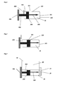
Figure 1 shows a schematic view of one or more embodiments of the present invention, wherein the piston is in the first position; -
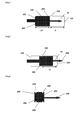
Figure 2 shows a schematic view of one or more embodiments of the present invention, wherein the piston is in the second position, sealing the opening, and piercing an end of the piston chamber; -
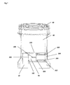
Figure 3 shows a schematic view of one or more embodiments of the present invention; -
Figure 4 shows a schematic view of one or more embodiments of the present invention; -
Figure 5 shows a schematic view of one or more embodiments of the present invention; -
Figure 6 shows a schematic view of a piston in accordance with one or more embodiments of the present invention; -
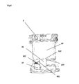
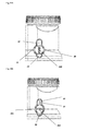
Figure 7 shows a sectional view of a test device in accordance with one or more embodiments of the present invention; -
Figure 8 shows a sectional view of a test device in accordance with one or more embodiments of the present invention; -
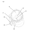
Figure 9 shows a 3D view of a test device in accordance with one or more embodiments of the present invention; -
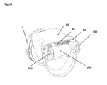
Figure 10 shows a 3D view of a test device in accordance with one or more embodiments of the present invention; -
Figures 11A and 11B show 3D views of a test device in accordance with one or more embodiments of the present invention; - The following explanation made for the structures of the present invention or the technical terms are not intended to limit the scope of the present invention.
- Testing is to analyze or detect the existence of a substance or a material, such as, but are not limited to, chemicals, organic compounds, inorganic compounds, metabolites, drugs or drug metabolites, organism and organism metabolites, nucleic acid, protein, or polymer. In addition, testing also refers to quantifying the substance or material. Further, testing refers to immunoassay tests, chemical tests, and enzymatic detection, etc.
- A sample in the present invention refers to a substance with which the existence of certain interesting substance can be tested, analyzed or diagnosed in an analyte. For example, a sample can be a liquid sample, such as blood, plasma, serum, urine, saliva, and various exudates, or a solution transformed from a solid sample or semi-solid sample after pre-treatment. The collected sample can be used for testing the presence of an analyte with such methods as immunoassay, chemical detection and enzymatic detection, etc.
- A sample can be in liquid, which includes various kinds of body fluid, such as blood, serum, plasma, saliva, urine, tears, semen and marrow; a liquid sample can be a water sample, such as sea water, river water, household water, municipal water, industrial water, runoff water and sewage.
- The present invention relates to a device and methods to analyze all analytes, and the analytes can be detected in all liquid samples or liquefied samples, such as urine, saliva, saliva, blood, plasma or serum.
- An analyte in accordance with one or more embodimens of the present invention can be "drugs of abuse" (DOA) or any other interesting substance(s) in the sample. "Drugs of abuse" (DOA) refer to the drugs for non-medical purpose (often with nerve paralysis effect). The abuse of such drugs can cause physical and mental damages, leading to dependency, addiction and/or death. Typical examples include cocaine and amphetamine (such as Black Beauty, White Benny). Such drugs can break down into different small molecules once absorbed by the body, which exist in blood, urine, saliva, sweat and other body liquids, or the small molecules are present in part of the body liquid(s).
- A device in accordance with one or more embodiments of the present invention can employ a variety of test strips, which is determined by the analyte and the test purpose. The test strips can be roughly divided into two categories: detection test strips and adulteration test strips. A detection test strip may be used to test the composition of a test sample; an adulteration test strip may be used to test a substance with a certain nature contained in a test sample. Both categories may comprise a loading zone and a test zone.
- Detection test strip: Various detection test strips can be adopted in accordance with one or more embodiments of the present invention. Detection test strips may be used for immunoassay, chemical detection and testing for an analyte in a test sample. Such analytes may involve drugs of abuse, or metabolites that can imply one's health state.
- For example, "drugs of abuse" (DOA) described above may be legal for medical purpose, but prone to overdose, and can be detected with a test strip of the present invention. Such drugs may include tricyclic antidepressants (imipramine and its analogues) and OTC products containing acetaminophen (such as pharmaceuticals trademark Tylenol provided by McNeil-PPC, located in Washington, Pennsylvania). Such test can help emergency personnel determine whether a patient in a coma has accidentally overdosed any of these drugs.
- Detection test strips may be in various forms. In general, test strips may be made of absorbent materials, which may comprise a loading zone, a raw material zone and a test result zone. For example, a sample is added to the loading zone, moistens the raw material zone by capillary forces, dissolves and mixes the raw materials needed by the analyte at the raw material zone (if any in the sample). The mixed raw material sample continues to moist the test result zone, and the extra material is immobilized in the test result zone. These materials react with the analyte (if any) or one of the materials of the first group in the raw material zone. If the analyte does exist in the sample, a signal will appear in the test zone; otherwise, it will not.
- Detection test strips described in the following US patents or patent applications may be used according to one or more embodiments of this invention:
5,252,496 ,5, 415,994 ,5,559,041 ,5,602,040 ,5,656,503 ,5,712,170 ,5,877,028 ,5,965,458 ,6,046,058 ,6,136,610 ,6,140,136 ,6,183,972 ,6,187,268 ,6,187,598 ,6,194,221 ,6,194,224 ,6,221,678 ,6,228,660 ,6,241,689 ,6,248,598 ,6,271,046 ,6,297,020 ,6,316,205 , and6,372,514 . - Adulteration test strip: Adulteration test strips aim to test a physical characteristic of a test sample or a contamination, such as temperature, specific gravity, pH, oxidant pollution, glutaconaldehyde pollution, nitrite pollution, ascorbic acid vitamin C pollution and creatinine contamination. For this test purpose, the following test strips may be used. Test strips may have combined the reagents used to test extra chemicals or compromise a test result and conceal a drug taking behavior due to other reasons.
- Test strips for testing the material properties of a liquid sample may be used according to one or more embodiments of the present invention. Such strips may include absorbent materials for transporting liquid samples through the test strips, filter components in liquid communication with absorbent materials, a raw material pad in liquid communication with the filter components, and an optional transparent lid. A raw material pad may comprise the raw material used to produce a detectable symbol, which is associated with the feature(s) of the sample, and observable through the transparent lid and the transparent plate of this device (if applied). A filter component can be made of the material(s) capable of prohibiting liquid(s) from flowing from the raw material pad back to the absorbent material.
- "Prohibition of reflux" refers to the liquid flowing from the raw material pad to the absorbent material is in such a small quantity that it will not change the test result, or the quantity of the raw material transferred from the raw material pad to the absorbent material or to the adjacent raw material pad is so small that it cannot be detected or will not lead to any unclear result.
- The test strips may also include some immoistenable materials set between part of the filter materials and the absorbent materials. Such immoistenable materials may prohibit the reflux of the sample from the raw material pad to the absorbent material. The liquid sample may be transmitted through the entire test strip by the capillarity action, which refers to a physical effect, well known to technical personnel, that is generated through an interactive reaction between a liquid and a wall or material, and this physical effect can cause liquids to be transmitted through the material.
- "Absorbent material" refers to the material that can easily attract or absorb liquids, and is suitable for capillarity action to guide liquids from one point to another point of this material.
- "Filter component" can facilitate a uniform diffusion of the sample when it flows to the raw material pad, so as to form detectable symbols in proper order and in a homogenous manner. A filter component can also prohibit the sample from flowing from the raw material pad back to the absorbent material. Also, it can prevent the chemical substances of the raw material from being transferred from one raw material pad to another.
- "Immoistenable material" refers to the material that does not allow any quantity of the liquid that can change the test result to flow through, and often serves as a liquid flow barrier.
- In accordance with one or more embodiments, a
piston chamber 100 may have the shape of a cylinder, as shown for example inFig.1 . The middle of the cylinder may be hollow, thus defining a cavity of the piston chamber, and both ends of thepiston chamber 100 may be open. Apiston 200 is inserted from anopening 104 of thepiston chamber 100 into thepiston chamber 100. Anouter edge 201 of thepiston 200 contacts aninner wall 102 of thepiston chamber 100, so as to seal theopening 104 of thepiston chamber 100, and keep the liquid sample in the piston chamber without spill-over. - In accordance with one or more embodiments, the
outer edge 201 of thepiston 200 may be provided withgrooves Fig. 6 . One or more resilient sealing rings 501 may be disposed within thegrooves inner wall 102 of thepiston 200, thus achieving a sealing effect. The number of sealing rings can be 1, 2 or larger, and can be set separately above the grooves. When thepiston 200 is thick enough, the grooves can be set at both ends 202 and 205 of the outer edge of the piston, with asealing ring 501, respectively, installed in bothgrooves outer edge 201 of the piston and theinner wall 102 of the piston chamber. In addition to such sealing method, a bolt, a snap or other forms can also be used to seal between thepiston 200 and thepiston chamber 100. - The
other end 101 of thepiston chamber 100 may be sealed by a sealingmaterial 900 that can be easily pierced, such as for example a puncturable sealing fin, a puncturable double-sided adhesive, or other puncturable films, including aluminum foil, thin plastic sheet, latex, rubber, and so on. In addition, the sealingmaterial 900 used to seal theother end 101 of the piston chamber can also be breathable, water-proof and puncturable. Thesealed end 101 of the piston chamber, theother end 205 of thepiston 200, and theinner wall 103 of the piston chamber collectively form thepiston cavity 70, which receives part of the liquid sample from the collectingchamber 80 through theopening 103. In the meanwhile, thepiston cavity 70 also transfers the liquid sample inside the collectingchamber 80 to thetest chamber 10 through the motion of the piston. Thus, thepiston cavity 70 is restrained by theother end 205 of thepiston 200, theend 101 of thepiston chamber 100 and thewall 103 of the piston. - In accordance with one or more embodiments, in order to urge a smooth access of part of the liquid sample from the collecting chamber to the
piston cavity 70, anopening 103 or a passage on the wall of the piston chamber is set so as to establish a liquid communication between the collectingchamber 80 and thepiston cavity 70. Thus, when there is any liquid sample collected in the collecting chamber, it will be released in the piston cavity or even fill the piston cavity through the opening or passage without difficulty. In order to accelerate an accurate flow of the liquid sample from the collectingchamber 80 into thetest chamber 10, thepiston 200 at the initial state is generally set next to theopening 103, or leaves the opening or the passage semi-sealed. Thus, when any liquid sample is collected in the collecting chamber, thanks to the liquid communication between theopening 103 and thepiston cavity 70, the liquid sample will be naturally released from the collecting chamber into the piston cavity. At this time, the piston is located at the first position, as shown for example inFigures 1 and4 . As the puncturable sealing fin, the double-sided adhesive or other films seal theother end 108 of the piston cavity 70 (at this time, part of the space in thepiston chamber 100 is confined to be thepiston cavity 70, and theother end 101 of the piston chamber has naturally become the bottom 108 of the piston cavity70), apuncturing component 300 is set on thepiston 200, and this puncturing component can pierce the sealingmaterial 900 used to seal the other end of the piston chamber. - In accordance with one or more embodiments, this
puncturing component 300 is set inside thepiston cavity 70 and on thepiston 200. In addition, we set the distance between the piercingend 301 of the puncturing component and the sealingmaterial 900 or theother end 101 of the piston chamber smaller than or equal to the length of the opening on the piston chamber. When thepiston 200 moves toward theother end 101 of the piston chamber inside thepiston chamber 100, once theouter edge 201 of the piston substantially and completely seals theopening 103, thepuncturing component 300 pierces the sealingmaterial 900 that seals theother end 101 of thepiston chamber 100, so that the liquid sample is released immediately from thepiston cavity 70 into the test chamber through the pierced sealing material. The liquid sample in thetest chamber 10 contacts atest component 20 disposed in thetest chamber 10, and thus theopening 103 is sealed and the sealingmaterial 900 is pierced virtually at the same time. "Virtually" sealing theopening 103 herein means that the opening is sealed by the outer edge of the piston, preventing the liquid sample returning from the collectingchamber 80 into thepiston cavity 70. In general, as the piston is pushed at a high speed, the opening is sealed and the sealing material is pierced at the same moment, which increases the working efficiency. Especially, during manual operation, the comfort can be improved. - In accordance with one or more embodiments, the sealing
material 900 used to seal one end of the piston chamber is breathable and water-proof. In accordance with one or more embodiments, such breathable and water-proof materials can be easily puncturable. - In accordance with one or more embodiments, the sealing
material 900 used to seal theend 101 of the piston chamber is not sealing film that can be easily pierced, but a plug, such as a silica gel plug. When thepiston 200 moves inside thepiston cavity 70 or thepiston chamber 100, theouter edge 201 of thepiston 100 seals the opening 103 (i.e., the opening or passage between the piston cavity and the collecting chamber). In the meanwhile, the push rod set on thepiston 100 and inside the piston cavity (the puncturing component does not have a sharp tip but non-sharp top) moves forward together, and pushes out the plug, which according to one or more embodiments may seal one end of the piston chamber sealing thebottom 108 of thepiston cavity 70, so as to make the liquid sample flow from the piston cavity into thetest chamber 10. Using a plug may be better than piercing a sealing material, because after the plug is pushed out, the bottom of the piston cavity is virtually completely opened, which facilitates the flow of the liquid sample into the test chamber, while the puncturing component usually pierces a small opening, then tears it open, in which case it may be difficult for the liquid to flow out of the piston cavity, compared with the embodiment in which a plug is used. - According to one or more embodiments, when the
piston 200 moves inside thepiston chamber 100, the volume of thepiston cavity 70 can be compressed. If the sealing material at the other end of the piston chamber is resilient (SeeFigure 8 , wherein the dottedline 901 represents the uncompressed state of a resilient material), the movable piston can cause such resilient material 90 to raise outwardly (see line 902), so as to compress the volume of thepiston cavity 70, for example as described above. According to one or more embodiments, thepuncturing component 300 does not have to be set inside the piston cavity, but on the outside thepiston cavity 70, as for example shown inFigure 8 . When the piston is at the initial position, thesharp tip 301 of the puncturing component is set next to the sealing component, without piercing it. At this time, the resilient component can form a slight projection as the result of overcoming the pressure of the liquid, and such projection fails to be substantially pierced. When thepiston 200 moves inside thepiston cavity 70, once theouter edge 201 of the piston seals theopening 103 between thepiston cavity 70 and the collectingchamber 80, the instant when the opening is sealed, the entire piston cavity enters into a confined state. The piston will continue to move a little more forward by, for example, 1-2 mm, which may be due to the inertia of the piston movement. Thus, thepiston 200 compresses the volume of thepiston cavity 70, and the resilient material projects toward the outside of the piston cavity due to the outer forces (seeFigure 8 ). Once the projecting part contacts the puncturing tip of the puncturing component, the resilient material is pierced, and the liquid sample is released from the piston cavity into the test chamber. Such resilient material may be also easily puncturable, and may be for example in the form of a thin rubber film. - In accordance with one or more embodiments, in order to make all the liquid flow from the
piston cavity 70 into thetest chamber 10 to achieve contact with thetest component 20 in the test chamber, it is necessary to ensure that each final yield of the liquid sample in the device equals the test chamber in volume, and the thickness h*of the piston 200 (or the length of the outer edge of the piston 201) virtually equals the length or depth h of thepiston cavity 70. Thus, when thepiston 200 is at its initial position, theouter edge 205 of the piston is near theopening 103 between thepiston cavity 70 and the collecting chamber 80 (seeFigure 4 ), or the outer edge semi-seals the opening, so that the liquid sample can flow smoothly from the collecting chamber into the piston cavity. If there is liquid sample in the collecting chamber, e.g. urine, when the piston is at the first position, theentire piston 200 is located on one side of the opening and inside thepiston chamber 100. As the piston is pushed, once theouter edge 201 of the piston seals theopening 103, thepuncturing component 300 inside the piston cavity pierces the sealingmaterial 900 that seals theother end 101 of thepiston chamber 100; or the push rod inside the piston cavity pushes open the sealing lid (silica gel lid) that seals theother end 101 of the piston chamber. At this moment, the liquid sample flows from thepiston cavity 70 into the test chamber. At the same time, the liquid sample in the collectingchamber 80 can no longer return to thepiston cavity 70. As the piston continues to move inside the piston cavity, as a matter of fact, the volume of the piston cavity has been gradually reduced, and thepiston 200 can press all the liquid from thepiston cavity 70 into the test chamber. While compressing thepiston cavity 70, theouter edge 201 of the piston keeps sealing theopening 103 with thepiston cavity 70, so that the liquid sample cannot return from the collecting chamber to the piston cavity 70 (seeFigure 5 ). To make sure that thepiston 200 can keep sealing theopening 103 during its motion, one or twogrooves outer edge 201 of the piston, and resilient sealing rings 501 and 502 may be disposed in the grooves. When thepiston 200 moves to the bottom of the piston cavity 70 (i.e., theother end 101 of the piston chamber), theresilient sealing components opening 103, and thus increasing the sealing effectiveness of the piston. - As compared to conventional devices, embodiments of the present invention can achieve a more precisely quantification result. For example, as described in the
U.S. patent No. 7,270,958 , the volume of the piston cavity 216 is fixed. After the opening between the piston cavity and the collecting chamber 208 is sealed, the piston cavity overall moves to the next position. Even so, some of the liquid sample can flow from the piston cavity into thetest chamber 300, but the quantity is not accurate, because the test chamber can be in a confined state sometimes (to prevent the liquid in the test chamber from leaking outside the device). Therefore, the liquid inside the piston cavity needs to overcome the pressure from the test chamber, and cannot flow into the test chamber entirely and naturally. However, as the piston according to one or more embodiments of the present invention compresses the volume of the piston cavity, which can virtually force all the liquid sample to flow from the piston cavity into the test chamber, one or more embodiments of the present invention result in a more precise sampling. In addition, one or more embodiments of the present invention not only quantify accurately, but also make the piston move fast in the piston chamber, so as to reduce the friction between the piston and the piston chamber and save operational efforts. Further, the conventional piston cavity moves in whole, which requires sealing the piston and the inner wall of the piston chamber so as to prevent the liquid from leaking. For this purpose, it is necessary to increase the force between the piston and the piston chamber, which inevitably adds the forces to push the piston, and make the operation more difficult. In practical operation of the product, when the operator needs to continuously operate multiple devices, it is important that he/she applies the least force possible. One or more embodiments of the present invention overcome the problems of conventional designs, adopt completely different configurations, reduce the force exerted on the piston, and improve the operational efficiency and the accuracy of sample loading. - In accordance with one or more embodiments, the
opening 103 or passage between the collectingchamber 80 and thepiston cavity 70 may have a predetermined size. If the opening is designed too small, it may be difficult for the liquid to flow smoothly from the collecting chamber into the piston cavity due to the surface tension, and thus thepiston cavity 70 may not be filled, or bubbles may be present in thepiston cavity 70. If theopening 103 is too large, it may be difficult to seal it with the outer edge of the piston. Results from tests prove that 5-8 mm is optimal for the opening of the piston in width. - In order to maintain the piston stably at the first position, instead of motioning or moving freely inside the
piston cavity 70, or allowing sample collecting personnel to mistakenly push the piston in advance, apush rod 400 is set on oneend 202 of the piston. Thispush rod 400 may be integrated with thepiston 200. A snap joint 600 may be provided on thepush rod 400 to maintain the piston stably at the first position, and to maintain theopening 103 stably in the state of open. In one or more embodiments, apush cap 500 may be provided on the piston push rod, with a width larger than the diameter of the piston. During the operation, the joint 600 may be removed, and thepush cap 500 may be pushed to get thepiston 200 to move inside thepiston chamber 100. Once thepush cap 500 moves for an appropriate distance, as the diameter of the push cap is larger than that of the piston, the push cap can only be pushed till the opening on one end of the piston chamber. Thus, the distance that the piston can cover in the piston chamber may be restrained by the piston rod and the push cap distance (seeFigure 1-3 ). - In accordance with one or more embodiments, as shown in
Figure 11A-11B , the piston position is not restrained with a block but by setting a pair of opposingbumps grooves groove 32, and theshorter bump 30 will be located oppositely with thegroove 33, then push the piston cap, so as to cause the piston to move inside the piston chamber. In order to prevent the sample collecting personnel to operate in advance, a seal can be affixed onto the piston cap; thus, once the seal is torn off, the piston is set in motion, which indicates that the sample collecting personnel may have pushed the piston in advance, and the credibility of the test result is compromised. Then, a new sample may be re-collected, which is particularly useful in drug test. - In accordance with one or more embodiments, the piston, piston push rod, push cap, the puncturing component (or the push rod) or the bumps of the piston cap can be molded, for example integrally. The grooves on the wall of the piston chamber and the piston chamber can also be molded, for example integrally, by injection molding.
- The collecting
chamber 80 is a chamber structure which may be used for collecting liquid samples. The collectingchamber 80 may share a wall with thepiston chamber 100, or thepiston chamber 100 may lie below the bottom of the collectingchamber 80 and maintain liquid communication with the collectingchamber 80 through theopening 103. The collectingchamber 80 may have an opening which may be sealed by a lid. The volume of the collecting chamber can be set at will, for example between 100 and 500 mm. Thetest chamber 10 may be located outside of the collecting chamber, and thetest component 20 may be disposed inside thetest chamber 10. The collecting chamber and thepiston chamber 100 as well as the position of thetest chamber 10 may be set as in conventional configurations. For example, the installation position as described in theU.S. patent Nos. 6,576,193 and7,270,959 can be used according to one or more embodiments of the present invention. In addition, the manufacturing materials for these parts may be produced with known plastic materials in this industry. It may be referred to the detailed descriptions ofU.S. patent No. 7,270,959 for exemplary settings of the test chamber, the collecting chamber and test components. According to one or more embodiments of the present invention, when the test component is disposed inside the test chamber, the test chamber may be transparent. Thus, the test result on the test strip can be read through the transparent test chamber. - In accordance with one or more embodiments, as shown for example in
Figures 7 and8 , a device may comprise a collectingchamber 80 having anopening 40 that can be sealed by alid 2. The way the lid seals the opening can be in a threaded structure or in the form of a bolt. At the bottom of the collecting chamber, there is an opening 13, which remains a liquid communication with the piston chamber. At theother end 103 of the piston chamber100, there may an opening, which may be sealed by the sealingmaterial 900. Such sealing material is puncturable, and may be in the form of a film, aluminum foil and double-sided adhesive, etc. Thepuncturing component 300 may be integrated with thepiston 200. On the outside of theother end 103 of the piston chamber is the test chamber. Test components may be disposed inside the test chamber, grooves may be formed on the piston, and resilient sealing rings 501 and 502 may be disposed in the grooves. Thepiston 200 may be set on one end of thepiston chamber 104. When the piston is located at the initial position, the end with the puncturing component is inside thepiston cavity 70, but it does not seal theopening 103. If any liquid sample is collected in the collectingchamber 80, under the gravity, the liquid sample will naturally flow into the piston cavity. So, at this time, if it is necessary to perform a test, it is advisable to preset joint 600 on the piston rod, push thepiston 200 to move toward theother end 101 of the piston chamber. As theopening 103 is sealed, the puncturing component pierces the sealingmaterial 900. At this time, as the opening is sealed, the liquid sample inside the collecting chamber cannot flow back to the piston cavity. In the meanwhile, since the puncturing component pierces the sealingmaterial 900, the liquid sample inside the piston cavity is released into the test chamber and contacts the test component, so as to complete the test on the analyte in the liquid sample. In order to get the liquid sample to flow from the piston cavity into the test chamber more smoothly, the piston continues to move after sealing theopening 103, compresses the volume of the piston cavity, and forces all the liquid sample to flow from the piston cavity into the test chamber, so as to complete quantifying the liquid sample accurately. - In accordance with one or more embodiments, as shown for example in
Figure 8 , a device includes a collectingchamber 80, which has anopening 40 that can be sealed by thelid 2. The way that the lid seals the opening can be in threaded structure or the form of a bolt. At the bottom of the collecting chamber, there is an opening 13, which remains a liquid communication with the piston chamber. At theother end 103 of the piston chamber100, there is an opening, which is sealed by the sealingmaterial 900. Such sealing material is resilient and puncturable, such as rubber film and plastic film. On the outside of theother end 103 of the piston chamber, opposite to the sealing material, we set a puncturing component. At this moment, the puncturing component is not inside the piston chamber, but outside the piston chamber instead. On the outside of theother end 103 of the piston chamber is the test chamber. We set test components inside the test chamber, grooves on the piston, and resilient sealing rings 501 and 502 in the grooves. Thepiston 200 is set on one end of thepiston chamber 104. When the piston is located at the initial position, the puncturing component is close to the sealing material, but without any contact. At this moment, the piston is on the side of theopening 103, but not sealing theopening 103. If any liquid sample is collected in the collectingchamber 80, under the gravity, the liquid sample will naturally flow into the piston cavity. So, at this time, if it is necessary to perform a test, it is advisable to preset a snap joint 600 on the piston rod, push thepiston 200 to move toward theother end 101 of the piston chamber. As theopening 103 is sealed, the puncturing component pierces the sealingmaterial 900. At this time, as the opening is sealed, the liquid sample inside the collecting chamber cannot flow back to the piston cavity. In the meanwhile, since the puncturing component pierces the sealingmaterial 900, the liquid sample inside the piston cavity is released into the test chamber and contacts the test component, so as to complete the test on the analyte in the liquid sample. At the same time when the piston sealing is opened, as the piston continues to move inside the piston cavity, the air pressure inside the piston cavity increases, which forces the resilient sealing film to bloat outwardly. Once the bloated resilient film contacts the puncturing component, it is pierced, and releases the liquid sample into the test chamber. In order to get the liquid sample to flow from the piston cavity into the test chamber more smoothly, the piston continues to move after sealing theopening 103, compresses the volume of the piston cavity, and forces all the liquid sample to flow from the piston cavity into the test chamber, so as to complete quantifying the liquid sample accurately. - In accordance with one or more embodiments, as shown for example in
Figure 9 , with respect to the embodiment shown inFigure 7 , the difference is that apiston push rod 400 is provided integrated with the piston, and apush cap 500 is provided on the piston push rod. Thepiston chamber 100 lies at the bottom of the collecting chamber, and anopening 103 is made on the wall of the piston, with a width of 3-8 mm. In the meanwhile, a snap joint 600 is set on the piston push rod, to maintain the piston to stably stay at the initial first position inside the piston chamber, that is, not to seal theopening 103. During the operation, the snap joint 600 is removed, thepush cap 500 is pushed to get the piston to move inside the piston chamber. At the same time when the piston seals the opening, it forces the liquid sample to flow from the piston chamber into the test chamber. The way to enter into the test chamber can be as in any of the embodiments as shown inFigures 1-8 . For example, the puncturing component pierces the sealing material, or the push-out component pushes out the sealing cap, or makes the sealing material resilient, and sets the puncturing component outside the piston cavity. Of course, in order to get the liquid sample to flow from the piston cavity into the test chamber more smoothly, the piston continues to move after sealing theopening 103, compresses the volume of the piston cavity, and forces all the liquid sample to flow from the piston cavity into the test chamber, so as to complete quantifying the liquid sample accurately. - In accordance with one or more embodiments, e.g., as shown in
Figure 10 , with respect to the embodiment shown inFigure 7 , the difference is that there is an opening on theend 101 of the piston chamber. On this opening, a sealing plug (such as a silica gel plug) is set to seal the opening. Also, a rod is set on the piston, which moves along with the piston. When theouter edge 201 of piston seals theopening 103, the push-out rod pushes the plug into the test chamber, and releases the liquid sample from the piston cavity into the test chamber. The liquid sample contacts the test component and completes the test of the analyte. In order to get the liquid sample to flow from the piston cavity into the test chamber more smoothly, the piston continues to move after sealing theopening 103, compresses the volume of the piston cavity, and forces all the liquid sample to flow from the piston cavity into the test chamber, so as to complete quantifying the liquid sample accurately. - We hereby describe embodiments of the present invention with reference to the attached drawings. Such description should not serve as limitations to the Claims in any manner, but serve to explain how to implement embodiments of the present invention.
- One thousand (1000) products are produced by the method as disclosed in the
U.S. patent No. 7,270,959 , and another 1000 devices of the present invention. The collecting chamber ofU.S. Patent No. 7,270,959 (the '959 product), with the volume of 450 ml, contains a liquid sample of 25 ml, so does the device of the present invention. In addition, the collecting chamber is the same as the piston chamber in the opening size and location as well as volume. Each device is filled with water or urine sample of 300ml, which shall be operated in manner described, respectively, to put the piston in three statuses by comparing toU.S. Patent No. 7,270,959 . The design of piston in the present invention is different from that inU.S. Patent No. 7,270,959 , and their operating modes substantially vary as well. Meanwhile, it is necessary to compare differences in the volume of the sample transferred into each test chamber and operastion duration.Table 1 Comparison on device parameters between the present invention and another product Leakage ratio Volume of urine in test chamber Volume of water in test chamber Volume of liquid in piston cavity Time of operation '959 product 20/1000 24.7 ml (average) 14.3 ml (average) 23.2 ml (average) 2.3 s The present invention 12/1000 24.3 ml (average) 23.8 ml (average) 24.8 ml (average) 1.5 s - It is particularly noted that the volume of urine that actually reaches the test chamber vary in a wide range. Among the 1000 urine cups, 300 of them have 14-18 ml of liquid actually reach the test chamber, 450 of them have 23-24.5ml, and 250 have 12-13.5 ml, indicating that the volumes of the urine actually reaching the test chambers, varying considerably, is difficult to measure, thus causing great differences to the test results. However, the present invention has made certain improvement, and achieved a result that about 950 urine cups having 22-24 ml reaching the test chamber, with about 50 having 20-21.5 ml.
Table 2 Comparison on degree of comfort and push force between the present invention and another product Push force on piston Degree of comfort '959 product 200.4 Newton 200(10 points), 300 (8 points), 400 (6 points), 100 (3 points) Present invention 120.45 Newton 400 (10 points), 500 (8 points), 80 (6 points), 20 (3 points) - The degree of comfort has been ranked based on the operation by over 1000 ordinary operators, with ranking standard as follows: 10 points-the most comfortable; 8 points—comfortable; 6 points—average; 3 points—uncomfortable.
Claims (15)
- A device for testing an analyte in a liquid sample, comprising:a test chamber (10) configured to contain one or more test components (20);a collecting chamber (80) configured to collect the liquid sample;a piston chamber (100) disposed between the test chamber (10) and the collecting chamber (80); andand a piston (200) with two ends disposed in the piston chamber (100);wherein one end (205) of the piston (200), one end (101) of the piston chamber (100) and a wall (102) of the piston chamber (100) form a piston cavity (70);wherein an opening (103) is set between the piston cavity (70) and the collecting chamber (80), wherein the piston (200) can move between two positions, a first position and a second position, in the piston chamber (100), wherein when the piston (200) is in the first position,liquid can flow between the piston chamber (100) and the collecting chamber (80) through the opening (103), wherein when the piston (200) moves from the first position to the second position, the opening (103) is sealed by the piston (200), wherein while the opening (103) is sealed by the piston (200), the liquid is released from the piston cavity (70) to the test chamber (10).
- The device according to claim 1, wherein the piston chamber (100) has two openings, wherein one of the two openings is configured to be sealed by the piston (200) and the other opening is sealed by a sealing material (900).
- The device according to claim 1 or claim 2, further comprising a puncturing component (300), wherein the sealing material (900) is puncturable, wherein when the piston (200) moves from the first position to the second position, the opening (103) between the piston cavity (70) and the collecting chamber (80) is sealed by the piston (200), wherein as the opening (103) is sealed, the puncturing component (300) pierces the sealing material (900), thereby releasing the liquid in the piston cavity (70) into the test chamber (10) through the pierced sealing material (900).
- The device according to claim 3, wherein the puncturing component (300) is located inside the piston cavity (70).
- The device according to claim 3 or claim 4, wherein the sealing material (900) is resilient and puncturable, wherein when the piston (200) moves from the first position to the second position, the resilient material (900) bulges outward from the other end of the piston chamber (100), and wherein the bulging resilient sealing material (900) is pierced by the puncturing component (300), thereby releasing the liquid sample from the piston cavity (70) to the test chamber (10) through the punctured resilient material (900).
- The device according to any one of claims 3-5, wherein the puncturing component is located outside of the piston chamber (100), facing the resilient and puncturable material (900), wherein the puncturing component is configured to pierce the resilient sealing material.
- The device according to any one of claims 1-6, wherein the sealing material (900) is breathable and water-proof.
- The device according to claim 6, wherein the resilient and puncturable material (900) is air tight.
- The device according to claim 7, wherein the resilient and puncturable material (900) is a latex, rubber or plastic film.
- The device according to claim 1, wherein both ends of the piston chamber (100) are open, wherein one of the ends of the piston chamber (100) is sealed with the piston (200) and the other is sealed with a sealing plug, wherein the piston (200) comprises an ejecting component, and when the piston (200) moves from the first position to the second, the opening (103) between the piston cavity (70) and the collecting chamber (80) is sealed, wherein as the opening (103) is sealed, the ejecting component pushes the sealing plug out from the piston chamber (100), thereby releasing the liquid from the piston cavity (70) through its open end into the test chamber (10).
- The device according to claim 10, wherein the sealing plug is made of silica gel.
- The device according to any one of claims 1-11, wherein the opening (103) set between the piston cavity (70) and the collecting chamber (80) is configured to be sealed with its outer edge.
- The device according to any one of claims 1-11, wherein after the opening (103) set between the piston cavity (70) and the collecting chamber (80) is sealed with its outer edge, the piston (200) will continue its motion inside the piston chamber (100), compress the volume of the piston cavity (70), and thus force the quantitative liquid sample release from the piston cavity (70) to the test chamber (10).
- The device according to any one of claims 1-11, wherein the length of the piston (200) substantially equals the depth of the piston chamber (100), and when the piston (200) is in the first position, one end of the piston (200) gets close to the opening (103) between the piston cavity (70) and the collecting chamber (80) without sealing the opening (103), while the other end remains inside the piston chamber (100) and stays far away from the opening (103) between the piston cavity (70) and the collecting chamber (80).
- The device according to any one of claims 1-11, wherein the piston (200) is integrated with a piston rod (400) and a piston cap (500), with a pair of opposed bumps (30, 31) on the piston cap (500), wherein against such bumps (30, 31) there is a groove in their vertical direction, and when the bumps (30, 31) remain at a horizontal position, their motion is completely limited by leaning against the outer wall of the collecting chamber (80); when the piston cap (500) rotates 90 degrees, the bumps (30, 31) move into the groove and thus the piston cap (500) can be pushed.
Applications Claiming Priority (2)
| Application Number | Priority Date | Filing Date | Title |
|---|---|---|---|
| CN201320894525 | 2013-12-31 | ||
| CN201310755002.7A CN103760330B (en) | 2013-12-31 | 2013-12-31 | A kind ofly to collect and the device of analyte in test fluid sample |
Publications (2)
| Publication Number | Publication Date |
|---|---|
| EP2889086A1 true EP2889086A1 (en) | 2015-07-01 |
| EP2889086B1 EP2889086B1 (en) | 2017-06-21 |
Family
ID=52440513
Family Applications (1)
| Application Number | Title | Priority Date | Filing Date |
|---|---|---|---|
| EP14200592.5A Not-in-force EP2889086B1 (en) | 2013-12-31 | 2014-12-30 | A device for collecting and testing analyte in a liquid sample |
Country Status (2)
| Country | Link |
|---|---|
| US (1) | US9352313B2 (en) |
| EP (1) | EP2889086B1 (en) |
Families Citing this family (3)
| Publication number | Priority date | Publication date | Assignee | Title |
|---|---|---|---|---|
| EP3069118A4 (en) * | 2013-11-14 | 2017-07-05 | Abon Biopharm (Hangzhou) Co., Ltd. | A device and method for using the device |
| EP3374768B1 (en) * | 2015-11-09 | 2021-03-10 | Novamed Ltd. | Body liquids collection and diagnostic device |
| CN108186055B (en) * | 2018-02-07 | 2023-06-20 | 合肥市第二人民医院 | Medical pH value detection belt and urine pH value detection method thereof |
Citations (27)
| Publication number | Priority date | Publication date | Assignee | Title |
|---|---|---|---|---|
| US3422996A (en) * | 1966-11-25 | 1969-01-21 | Valve Corp Of America | Safety actuator cap for hand-held dispensers |
| US3739941A (en) * | 1971-04-26 | 1973-06-19 | Federal Tool & Plastics Uca Co | Actuator means for use with aerosol dispensers |
| US5252496A (en) | 1989-12-18 | 1993-10-12 | Princeton Biomeditech Corporation | Carbon black immunochemical label |
| US5415994A (en) | 1993-08-02 | 1995-05-16 | Quidel Corporation | Lateral flow medical diagnostic assay device with sample extraction means |
| US5602040A (en) | 1987-04-27 | 1997-02-11 | Unilever Patent Holdings B.V. | Assays |
| US5656503A (en) | 1987-04-27 | 1997-08-12 | Unilever Patent Holdings B.V. | Test device for detecting analytes in biological samples |
| US5712170A (en) | 1992-12-29 | 1998-01-27 | Oy Medix Biochemica Ab | Test strip, its production and use |
| US5877028A (en) | 1991-05-29 | 1999-03-02 | Smithkline Diagnostics, Inc. | Immunochromatographic assay device |
| US6046058A (en) | 1998-11-20 | 2000-04-04 | Sun; Ming | Color-coded test strip |
| US6136610A (en) | 1998-11-23 | 2000-10-24 | Praxsys Biosystems, Inc. | Method and apparatus for performing a lateral flow assay |
| US6140136A (en) | 1998-09-18 | 2000-10-31 | Syntron Bioresearch, Inc. | Analytical test device and method of use |
| US6183972B1 (en) | 1998-07-27 | 2001-02-06 | Bayer Corporation | Method for the determination of analyte concentration in a lateral flow sandwich immunoassay exhibiting high-dose hook effect |
| US6187268B1 (en) | 1998-07-27 | 2001-02-13 | Bayer Corporation | Transparent flow through membrane for dry reagent analytical devices |
| US6194221B1 (en) | 1996-11-19 | 2001-02-27 | Wyntek Diagnostics, Inc. | Hybrid one-step immunochromatographic device and method of use |
| US6194224B1 (en) | 1998-07-27 | 2001-02-27 | Avitar, Inc. | Diagnostic membrane containing fatty acid sarcosinate surfactant for testing oral fluid |
| US6221678B1 (en) | 1997-10-06 | 2001-04-24 | Enterix Inc | Apparatus and method for analyte detection |
| US6241689B1 (en) | 1995-11-13 | 2001-06-05 | Provalis Uk Limited | Diagnostic test apparatus |
| US6248598B1 (en) | 1998-09-17 | 2001-06-19 | Stuart C. Bogema | Immunoassay that provides for both collection of saliva and assay of saliva for one or more analytes with visual readout |
| US6271046B1 (en) | 1997-10-06 | 2001-08-07 | Enterix, Inc. | Apparatus and method for analyte detection |
| US6297020B1 (en) | 1999-03-01 | 2001-10-02 | Bayer Corporation | Device for carrying out lateral-flow assays involving more than one analyte |
| US6316205B1 (en) | 2000-01-28 | 2001-11-13 | Genelabs Diagnostics Pte Ltd. | Assay devices and methods of analyte detection |
| US6372514B1 (en) | 1998-09-18 | 2002-04-16 | Syntron Bioresearch, Inc. | Even fluid front for liquid sample on test strip device |
| US6576193B1 (en) | 2000-10-27 | 2003-06-10 | Shujie Cui | Device and method for collecting and testing fluid specimens |
| WO2005023426A2 (en) * | 2003-08-25 | 2005-03-17 | Oakville Hong Kong Co., Limited | Biological specimen collection and analysis system |
| US7270959B2 (en) | 2001-07-25 | 2007-09-18 | Oakville Hong Kong Company Limited | Specimen collection container |
| US7270958B2 (en) | 1998-09-10 | 2007-09-18 | The Regents Of The University Of Michigan | Compositions and methods for analysis of nucleic acids |
| US20130045501A1 (en) * | 2010-03-25 | 2013-02-21 | Lin Hu | Detection Device for Detecting Analytes in Liquid Specimen |
Family Cites Families (4)
| Publication number | Priority date | Publication date | Assignee | Title |
|---|---|---|---|---|
| US6277646B1 (en) * | 1997-05-05 | 2001-08-21 | Dade Behring Inc. | Fluid specimen collecting and testing apparatus |
| US6016712A (en) * | 1997-09-18 | 2000-01-25 | Accumetrics | Device for receiving and processing a sample |
| EP1390466A4 (en) * | 2001-04-26 | 2010-07-28 | Pressure Biosciences Inc | Multichamber device and uses thereof for processing of biological samples |
| US7300633B2 (en) * | 2001-07-25 | 2007-11-27 | Oakville Hong Kong Company Limited | Specimen collection container |
-
2014
- 2014-06-27 US US14/318,489 patent/US9352313B2/en not_active Expired - Fee Related
- 2014-12-30 EP EP14200592.5A patent/EP2889086B1/en not_active Not-in-force
Patent Citations (31)
| Publication number | Priority date | Publication date | Assignee | Title |
|---|---|---|---|---|
| US6228660B1 (en) | 1908-04-27 | 2001-05-08 | Conopco Inc. | Capillary immunoassay and device therefor comprising mobilizable particulate labelled reagents |
| US3422996A (en) * | 1966-11-25 | 1969-01-21 | Valve Corp Of America | Safety actuator cap for hand-held dispensers |
| US3739941A (en) * | 1971-04-26 | 1973-06-19 | Federal Tool & Plastics Uca Co | Actuator means for use with aerosol dispensers |
| US5656503A (en) | 1987-04-27 | 1997-08-12 | Unilever Patent Holdings B.V. | Test device for detecting analytes in biological samples |
| US6187598B1 (en) | 1987-04-27 | 2001-02-13 | Conopco Inc. | Capillary immunoassay and device therefor comprising mobilizable particulate labelled reagents |
| US5602040A (en) | 1987-04-27 | 1997-02-11 | Unilever Patent Holdings B.V. | Assays |
| US5559041A (en) | 1989-12-18 | 1996-09-24 | Princeton Biomeditech Corporation | Immunoassay devices and materials |
| US5252496A (en) | 1989-12-18 | 1993-10-12 | Princeton Biomeditech Corporation | Carbon black immunochemical label |
| US5877028A (en) | 1991-05-29 | 1999-03-02 | Smithkline Diagnostics, Inc. | Immunochromatographic assay device |
| US5712170A (en) | 1992-12-29 | 1998-01-27 | Oy Medix Biochemica Ab | Test strip, its production and use |
| US5965458A (en) | 1992-12-29 | 1999-10-12 | Oy Medix Biochemica A.B. | Test strip, its production and use |
| US5415994A (en) | 1993-08-02 | 1995-05-16 | Quidel Corporation | Lateral flow medical diagnostic assay device with sample extraction means |
| US6241689B1 (en) | 1995-11-13 | 2001-06-05 | Provalis Uk Limited | Diagnostic test apparatus |
| US6194221B1 (en) | 1996-11-19 | 2001-02-27 | Wyntek Diagnostics, Inc. | Hybrid one-step immunochromatographic device and method of use |
| US6271046B1 (en) | 1997-10-06 | 2001-08-07 | Enterix, Inc. | Apparatus and method for analyte detection |
| US6221678B1 (en) | 1997-10-06 | 2001-04-24 | Enterix Inc | Apparatus and method for analyte detection |
| US6187268B1 (en) | 1998-07-27 | 2001-02-13 | Bayer Corporation | Transparent flow through membrane for dry reagent analytical devices |
| US6183972B1 (en) | 1998-07-27 | 2001-02-06 | Bayer Corporation | Method for the determination of analyte concentration in a lateral flow sandwich immunoassay exhibiting high-dose hook effect |
| US6194224B1 (en) | 1998-07-27 | 2001-02-27 | Avitar, Inc. | Diagnostic membrane containing fatty acid sarcosinate surfactant for testing oral fluid |
| US7270958B2 (en) | 1998-09-10 | 2007-09-18 | The Regents Of The University Of Michigan | Compositions and methods for analysis of nucleic acids |
| US6248598B1 (en) | 1998-09-17 | 2001-06-19 | Stuart C. Bogema | Immunoassay that provides for both collection of saliva and assay of saliva for one or more analytes with visual readout |
| US6372514B1 (en) | 1998-09-18 | 2002-04-16 | Syntron Bioresearch, Inc. | Even fluid front for liquid sample on test strip device |
| US6140136A (en) | 1998-09-18 | 2000-10-31 | Syntron Bioresearch, Inc. | Analytical test device and method of use |
| US6046058A (en) | 1998-11-20 | 2000-04-04 | Sun; Ming | Color-coded test strip |
| US6136610A (en) | 1998-11-23 | 2000-10-24 | Praxsys Biosystems, Inc. | Method and apparatus for performing a lateral flow assay |
| US6297020B1 (en) | 1999-03-01 | 2001-10-02 | Bayer Corporation | Device for carrying out lateral-flow assays involving more than one analyte |
| US6316205B1 (en) | 2000-01-28 | 2001-11-13 | Genelabs Diagnostics Pte Ltd. | Assay devices and methods of analyte detection |
| US6576193B1 (en) | 2000-10-27 | 2003-06-10 | Shujie Cui | Device and method for collecting and testing fluid specimens |
| US7270959B2 (en) | 2001-07-25 | 2007-09-18 | Oakville Hong Kong Company Limited | Specimen collection container |
| WO2005023426A2 (en) * | 2003-08-25 | 2005-03-17 | Oakville Hong Kong Co., Limited | Biological specimen collection and analysis system |
| US20130045501A1 (en) * | 2010-03-25 | 2013-02-21 | Lin Hu | Detection Device for Detecting Analytes in Liquid Specimen |
Also Published As
| Publication number | Publication date |
|---|---|
| EP2889086B1 (en) | 2017-06-21 |
| US20150185240A1 (en) | 2015-07-02 |
| US9352313B2 (en) | 2016-05-31 |
Similar Documents
| Publication | Publication Date | Title |
|---|---|---|
| JP4889743B2 (en) | Apparatus for detecting an analyte in a fluid sample | |
| EP2376918B1 (en) | Detection device with a collection chamber for a liquid sample and a detektion chamber in a lid | |
| EP3380837B1 (en) | Assay device | |
| CN102200536B (en) | Device for detecting analyzed objects in test liquid samples | |
| CN103760330B (en) | A kind ofly to collect and the device of analyte in test fluid sample | |
| US20160243544A1 (en) | A device and method for using the device | |
| CN105836240B (en) | Po Guan mechanisms, include the Po Guan mechanisms leakproofness test tube component and its application | |
| EP2889086B1 (en) | A device for collecting and testing analyte in a liquid sample | |
| CA3155849C (en) | Sample collection and detection device and method | |
| US10495635B2 (en) | Testing device for testing analytes in liquid samples | |
| CN106289933B (en) | Cover body and device for storing and mixing solid and liquid | |
| CN201666896U (en) | Device for detecting the analyte in testing liquid sample | |
| CN212410604U (en) | Detection device | |
| WO2022213407A1 (en) | Blood collection structure, and whole blood and fingerstick blood detection device and method | |
| CN217717044U (en) | Sample detection device | |
| US20220137042A1 (en) | Lateral Flow Assay Device And Sampling Methods | |
| CN205146256U (en) | Device that mixes solid and liquid |
Legal Events
| Date | Code | Title | Description |
|---|---|---|---|
| PUAI | Public reference made under article 153(3) epc to a published international application that has entered the european phase |
Free format text: ORIGINAL CODE: 0009012 |
|
| 17P | Request for examination filed |
Effective date: 20141230 |
|
| AK | Designated contracting states |
Kind code of ref document: A1 Designated state(s): AL AT BE BG CH CY CZ DE DK EE ES FI FR GB GR HR HU IE IS IT LI LT LU LV MC MK MT NL NO PL PT RO RS SE SI SK SM TR |
|
| AX | Request for extension of the european patent |
Extension state: BA ME |
|
| R17P | Request for examination filed (corrected) |
Effective date: 20160104 |
|
| RBV | Designated contracting states (corrected) |
Designated state(s): AL AT BE BG CH CY CZ DE DK EE ES FI FR GB GR HR HU IE IS IT LI LT LU LV MC MK MT NL NO PL PT RO RS SE SI SK SM TR |
|
| STAA | Information on the status of an ep patent application or granted ep patent |
Free format text: STATUS: EXAMINATION IS IN PROGRESS |
|
| 17Q | First examination report despatched |
Effective date: 20161108 |
|
| GRAP | Despatch of communication of intention to grant a patent |
Free format text: ORIGINAL CODE: EPIDOSNIGR1 |
|
| STAA | Information on the status of an ep patent application or granted ep patent |
Free format text: STATUS: GRANT OF PATENT IS INTENDED |
|
| INTG | Intention to grant announced |
Effective date: 20170102 |
|
| GRAS | Grant fee paid |
Free format text: ORIGINAL CODE: EPIDOSNIGR3 |
|
| GRAA | (expected) grant |
Free format text: ORIGINAL CODE: 0009210 |
|
| STAA | Information on the status of an ep patent application or granted ep patent |
Free format text: STATUS: THE PATENT HAS BEEN GRANTED |
|
| AK | Designated contracting states |
Kind code of ref document: B1 Designated state(s): AL AT BE BG CH CY CZ DE DK EE ES FI FR GB GR HR HU IE IS IT LI LT LU LV MC MK MT NL NO PL PT RO RS SE SI SK SM TR |
|
| REG | Reference to a national code |
Ref country code: GB Ref legal event code: FG4D |
|
| REG | Reference to a national code |
Ref country code: CH Ref legal event code: EP |
|
| RIN2 | Information on inventor provided after grant (corrected) |
Inventor name: DAI, JIELIN |
|
| REG | Reference to a national code |
Ref country code: IE Ref legal event code: FG4D |
|
| REG | Reference to a national code |
Ref country code: AT Ref legal event code: REF Ref document number: 902439 Country of ref document: AT Kind code of ref document: T Effective date: 20170715 |
|
| REG | Reference to a national code |
Ref country code: DE Ref legal event code: R096 Ref document number: 602014010952 Country of ref document: DE |
|
| REG | Reference to a national code |
Ref country code: NL Ref legal event code: MP Effective date: 20170621 |
|
| PG25 | Lapsed in a contracting state [announced via postgrant information from national office to epo] |
Ref country code: GR Free format text: LAPSE BECAUSE OF FAILURE TO SUBMIT A TRANSLATION OF THE DESCRIPTION OR TO PAY THE FEE WITHIN THE PRESCRIBED TIME-LIMIT Effective date: 20170922 Ref country code: LT Free format text: LAPSE BECAUSE OF FAILURE TO SUBMIT A TRANSLATION OF THE DESCRIPTION OR TO PAY THE FEE WITHIN THE PRESCRIBED TIME-LIMIT Effective date: 20170621 Ref country code: NO Free format text: LAPSE BECAUSE OF FAILURE TO SUBMIT A TRANSLATION OF THE DESCRIPTION OR TO PAY THE FEE WITHIN THE PRESCRIBED TIME-LIMIT Effective date: 20170921 Ref country code: HR Free format text: LAPSE BECAUSE OF FAILURE TO SUBMIT A TRANSLATION OF THE DESCRIPTION OR TO PAY THE FEE WITHIN THE PRESCRIBED TIME-LIMIT Effective date: 20170621 Ref country code: FI Free format text: LAPSE BECAUSE OF FAILURE TO SUBMIT A TRANSLATION OF THE DESCRIPTION OR TO PAY THE FEE WITHIN THE PRESCRIBED TIME-LIMIT Effective date: 20170621 |
|
| REG | Reference to a national code |
Ref country code: LT Ref legal event code: MG4D |
|
| REG | Reference to a national code |
Ref country code: AT Ref legal event code: MK05 Ref document number: 902439 Country of ref document: AT Kind code of ref document: T Effective date: 20170621 |
|
| PG25 | Lapsed in a contracting state [announced via postgrant information from national office to epo] |
Ref country code: NL Free format text: LAPSE BECAUSE OF FAILURE TO SUBMIT A TRANSLATION OF THE DESCRIPTION OR TO PAY THE FEE WITHIN THE PRESCRIBED TIME-LIMIT Effective date: 20170621 Ref country code: LV Free format text: LAPSE BECAUSE OF FAILURE TO SUBMIT A TRANSLATION OF THE DESCRIPTION OR TO PAY THE FEE WITHIN THE PRESCRIBED TIME-LIMIT Effective date: 20170621 Ref country code: RS Free format text: LAPSE BECAUSE OF FAILURE TO SUBMIT A TRANSLATION OF THE DESCRIPTION OR TO PAY THE FEE WITHIN THE PRESCRIBED TIME-LIMIT Effective date: 20170621 Ref country code: SE Free format text: LAPSE BECAUSE OF FAILURE TO SUBMIT A TRANSLATION OF THE DESCRIPTION OR TO PAY THE FEE WITHIN THE PRESCRIBED TIME-LIMIT Effective date: 20170621 Ref country code: BG Free format text: LAPSE BECAUSE OF FAILURE TO SUBMIT A TRANSLATION OF THE DESCRIPTION OR TO PAY THE FEE WITHIN THE PRESCRIBED TIME-LIMIT Effective date: 20170921 |
|
| PG25 | Lapsed in a contracting state [announced via postgrant information from national office to epo] |
Ref country code: SK Free format text: LAPSE BECAUSE OF FAILURE TO SUBMIT A TRANSLATION OF THE DESCRIPTION OR TO PAY THE FEE WITHIN THE PRESCRIBED TIME-LIMIT Effective date: 20170621 Ref country code: RO Free format text: LAPSE BECAUSE OF FAILURE TO SUBMIT A TRANSLATION OF THE DESCRIPTION OR TO PAY THE FEE WITHIN THE PRESCRIBED TIME-LIMIT Effective date: 20170621 Ref country code: EE Free format text: LAPSE BECAUSE OF FAILURE TO SUBMIT A TRANSLATION OF THE DESCRIPTION OR TO PAY THE FEE WITHIN THE PRESCRIBED TIME-LIMIT Effective date: 20170621 Ref country code: AT Free format text: LAPSE BECAUSE OF FAILURE TO SUBMIT A TRANSLATION OF THE DESCRIPTION OR TO PAY THE FEE WITHIN THE PRESCRIBED TIME-LIMIT Effective date: 20170621 Ref country code: CZ Free format text: LAPSE BECAUSE OF FAILURE TO SUBMIT A TRANSLATION OF THE DESCRIPTION OR TO PAY THE FEE WITHIN THE PRESCRIBED TIME-LIMIT Effective date: 20170621 |
|
| PG25 | Lapsed in a contracting state [announced via postgrant information from national office to epo] |
Ref country code: IT Free format text: LAPSE BECAUSE OF FAILURE TO SUBMIT A TRANSLATION OF THE DESCRIPTION OR TO PAY THE FEE WITHIN THE PRESCRIBED TIME-LIMIT Effective date: 20170621 Ref country code: ES Free format text: LAPSE BECAUSE OF FAILURE TO SUBMIT A TRANSLATION OF THE DESCRIPTION OR TO PAY THE FEE WITHIN THE PRESCRIBED TIME-LIMIT Effective date: 20170621 Ref country code: IS Free format text: LAPSE BECAUSE OF FAILURE TO SUBMIT A TRANSLATION OF THE DESCRIPTION OR TO PAY THE FEE WITHIN THE PRESCRIBED TIME-LIMIT Effective date: 20171021 Ref country code: PL Free format text: LAPSE BECAUSE OF FAILURE TO SUBMIT A TRANSLATION OF THE DESCRIPTION OR TO PAY THE FEE WITHIN THE PRESCRIBED TIME-LIMIT Effective date: 20170621 Ref country code: SM Free format text: LAPSE BECAUSE OF FAILURE TO SUBMIT A TRANSLATION OF THE DESCRIPTION OR TO PAY THE FEE WITHIN THE PRESCRIBED TIME-LIMIT Effective date: 20170621 |
|
| REG | Reference to a national code |
Ref country code: DE Ref legal event code: R097 Ref document number: 602014010952 Country of ref document: DE |
|
| PLBE | No opposition filed within time limit |
Free format text: ORIGINAL CODE: 0009261 |
|
| STAA | Information on the status of an ep patent application or granted ep patent |
Free format text: STATUS: NO OPPOSITION FILED WITHIN TIME LIMIT |
|
| PG25 | Lapsed in a contracting state [announced via postgrant information from national office to epo] |
Ref country code: DK Free format text: LAPSE BECAUSE OF FAILURE TO SUBMIT A TRANSLATION OF THE DESCRIPTION OR TO PAY THE FEE WITHIN THE PRESCRIBED TIME-LIMIT Effective date: 20170621 |
|
| 26N | No opposition filed |
Effective date: 20180322 |
|
| REG | Reference to a national code |
Ref country code: DE Ref legal event code: R119 Ref document number: 602014010952 Country of ref document: DE |
|
| REG | Reference to a national code |
Ref country code: CH Ref legal event code: PL |
|
| PG25 | Lapsed in a contracting state [announced via postgrant information from national office to epo] |
Ref country code: SI Free format text: LAPSE BECAUSE OF FAILURE TO SUBMIT A TRANSLATION OF THE DESCRIPTION OR TO PAY THE FEE WITHIN THE PRESCRIBED TIME-LIMIT Effective date: 20170621 |
|
| PG25 | Lapsed in a contracting state [announced via postgrant information from national office to epo] |
Ref country code: MT Free format text: LAPSE BECAUSE OF NON-PAYMENT OF DUE FEES Effective date: 20171230 Ref country code: LU Free format text: LAPSE BECAUSE OF NON-PAYMENT OF DUE FEES Effective date: 20171230 |
|
| REG | Reference to a national code |
Ref country code: FR Ref legal event code: ST Effective date: 20180831 |
|
| REG | Reference to a national code |
Ref country code: IE Ref legal event code: MM4A |
|
| REG | Reference to a national code |
Ref country code: BE Ref legal event code: MM Effective date: 20171231 |
|
| PG25 | Lapsed in a contracting state [announced via postgrant information from national office to epo] |
Ref country code: DE Free format text: LAPSE BECAUSE OF NON-PAYMENT OF DUE FEES Effective date: 20180703 Ref country code: FR Free format text: LAPSE BECAUSE OF NON-PAYMENT OF DUE FEES Effective date: 20180102 Ref country code: IE Free format text: LAPSE BECAUSE OF NON-PAYMENT OF DUE FEES Effective date: 20171230 |
|
| PG25 | Lapsed in a contracting state [announced via postgrant information from national office to epo] |
Ref country code: LI Free format text: LAPSE BECAUSE OF NON-PAYMENT OF DUE FEES Effective date: 20171231 Ref country code: BE Free format text: LAPSE BECAUSE OF NON-PAYMENT OF DUE FEES Effective date: 20171231 Ref country code: CH Free format text: LAPSE BECAUSE OF NON-PAYMENT OF DUE FEES Effective date: 20171231 |
|
| PG25 | Lapsed in a contracting state [announced via postgrant information from national office to epo] |
Ref country code: MC Free format text: LAPSE BECAUSE OF FAILURE TO SUBMIT A TRANSLATION OF THE DESCRIPTION OR TO PAY THE FEE WITHIN THE PRESCRIBED TIME-LIMIT Effective date: 20170621 Ref country code: HU Free format text: LAPSE BECAUSE OF FAILURE TO SUBMIT A TRANSLATION OF THE DESCRIPTION OR TO PAY THE FEE WITHIN THE PRESCRIBED TIME-LIMIT; INVALID AB INITIO Effective date: 20141230 |
|
| GBPC | Gb: european patent ceased through non-payment of renewal fee |
Effective date: 20181230 |
|
| PG25 | Lapsed in a contracting state [announced via postgrant information from national office to epo] |
Ref country code: CY Free format text: LAPSE BECAUSE OF FAILURE TO SUBMIT A TRANSLATION OF THE DESCRIPTION OR TO PAY THE FEE WITHIN THE PRESCRIBED TIME-LIMIT Effective date: 20170621 |
|
| PG25 | Lapsed in a contracting state [announced via postgrant information from national office to epo] |
Ref country code: MK Free format text: LAPSE BECAUSE OF FAILURE TO SUBMIT A TRANSLATION OF THE DESCRIPTION OR TO PAY THE FEE WITHIN THE PRESCRIBED TIME-LIMIT Effective date: 20170621 |
|
| PG25 | Lapsed in a contracting state [announced via postgrant information from national office to epo] |
Ref country code: GB Free format text: LAPSE BECAUSE OF NON-PAYMENT OF DUE FEES Effective date: 20181230 |
|
| PG25 | Lapsed in a contracting state [announced via postgrant information from national office to epo] |
Ref country code: TR Free format text: LAPSE BECAUSE OF FAILURE TO SUBMIT A TRANSLATION OF THE DESCRIPTION OR TO PAY THE FEE WITHIN THE PRESCRIBED TIME-LIMIT Effective date: 20170621 |
|
| PG25 | Lapsed in a contracting state [announced via postgrant information from national office to epo] |
Ref country code: PT Free format text: LAPSE BECAUSE OF FAILURE TO SUBMIT A TRANSLATION OF THE DESCRIPTION OR TO PAY THE FEE WITHIN THE PRESCRIBED TIME-LIMIT Effective date: 20170621 |
|
| PG25 | Lapsed in a contracting state [announced via postgrant information from national office to epo] |
Ref country code: AL Free format text: LAPSE BECAUSE OF FAILURE TO SUBMIT A TRANSLATION OF THE DESCRIPTION OR TO PAY THE FEE WITHIN THE PRESCRIBED TIME-LIMIT Effective date: 20170621 |