EP2896375A1 - A drill guide - Google Patents
A drill guide Download PDFInfo
- Publication number
- EP2896375A1 EP2896375A1 EP15152599.5A EP15152599A EP2896375A1 EP 2896375 A1 EP2896375 A1 EP 2896375A1 EP 15152599 A EP15152599 A EP 15152599A EP 2896375 A1 EP2896375 A1 EP 2896375A1
- Authority
- EP
- European Patent Office
- Prior art keywords
- drill guide
- intramedullary rod
- statement
- arm
- alignment tool
- Prior art date
- Legal status (The legal status is an assumption and is not a legal conclusion. Google has not performed a legal analysis and makes no representation as to the accuracy of the status listed.)
- Granted
Links
- 238000005553 drilling Methods 0.000 description 17
- 210000000988 bone and bone Anatomy 0.000 description 8
- 238000002271 resection Methods 0.000 description 5
- 230000001419 dependent effect Effects 0.000 description 4
- 210000000689 upper leg Anatomy 0.000 description 4
- 210000003127 knee Anatomy 0.000 description 3
- 238000013150 knee replacement Methods 0.000 description 3
- 238000000034 method Methods 0.000 description 2
- 208000008558 Osteophyte Diseases 0.000 description 1
- 238000011882 arthroplasty Methods 0.000 description 1
- 230000000694 effects Effects 0.000 description 1
- 210000000629 knee joint Anatomy 0.000 description 1
- 238000003801 milling Methods 0.000 description 1
- 210000002303 tibia Anatomy 0.000 description 1
Images


Classifications
-
- A—HUMAN NECESSITIES
- A61—MEDICAL OR VETERINARY SCIENCE; HYGIENE
- A61B—DIAGNOSIS; SURGERY; IDENTIFICATION
- A61B17/00—Surgical instruments, devices or methods, e.g. tourniquets
- A61B17/16—Bone cutting, breaking or removal means other than saws, e.g. Osteoclasts; Drills or chisels for bones; Trepans
- A61B17/17—Guides or aligning means for drills, mills, pins or wires
- A61B17/1739—Guides or aligning means for drills, mills, pins or wires specially adapted for particular parts of the body
- A61B17/1764—Guides or aligning means for drills, mills, pins or wires specially adapted for particular parts of the body for the knee
-
- A—HUMAN NECESSITIES
- A61—MEDICAL OR VETERINARY SCIENCE; HYGIENE
- A61B—DIAGNOSIS; SURGERY; IDENTIFICATION
- A61B17/00—Surgical instruments, devices or methods, e.g. tourniquets
- A61B17/14—Surgical saws ; Accessories therefor
- A61B17/15—Guides therefor
-
- A—HUMAN NECESSITIES
- A61—MEDICAL OR VETERINARY SCIENCE; HYGIENE
- A61B—DIAGNOSIS; SURGERY; IDENTIFICATION
- A61B17/00—Surgical instruments, devices or methods, e.g. tourniquets
- A61B17/16—Bone cutting, breaking or removal means other than saws, e.g. Osteoclasts; Drills or chisels for bones; Trepans
- A61B17/17—Guides or aligning means for drills, mills, pins or wires
- A61B17/1717—Guides or aligning means for drills, mills, pins or wires for applying intramedullary nails or pins
-
- A—HUMAN NECESSITIES
- A61—MEDICAL OR VETERINARY SCIENCE; HYGIENE
- A61B—DIAGNOSIS; SURGERY; IDENTIFICATION
- A61B17/00—Surgical instruments, devices or methods, e.g. tourniquets
- A61B17/16—Bone cutting, breaking or removal means other than saws, e.g. Osteoclasts; Drills or chisels for bones; Trepans
- A61B17/17—Guides or aligning means for drills, mills, pins or wires
- A61B17/1725—Guides or aligning means for drills, mills, pins or wires for applying transverse screws or pins through intramedullary nails or pins
-
- A—HUMAN NECESSITIES
- A61—MEDICAL OR VETERINARY SCIENCE; HYGIENE
- A61B—DIAGNOSIS; SURGERY; IDENTIFICATION
- A61B17/00—Surgical instruments, devices or methods, e.g. tourniquets
- A61B17/16—Bone cutting, breaking or removal means other than saws, e.g. Osteoclasts; Drills or chisels for bones; Trepans
- A61B17/17—Guides or aligning means for drills, mills, pins or wires
- A61B17/1728—Guides or aligning means for drills, mills, pins or wires for holes for bone plates or plate screws
-
- A—HUMAN NECESSITIES
- A61—MEDICAL OR VETERINARY SCIENCE; HYGIENE
- A61B—DIAGNOSIS; SURGERY; IDENTIFICATION
- A61B17/00—Surgical instruments, devices or methods, e.g. tourniquets
- A61B17/56—Surgical instruments or methods for treatment of bones or joints; Devices specially adapted therefor
- A61B17/58—Surgical instruments or methods for treatment of bones or joints; Devices specially adapted therefor for osteosynthesis, e.g. bone plates, screws, setting implements or the like
- A61B17/68—Internal fixation devices, including fasteners and spinal fixators, even if a part thereof projects from the skin
- A61B17/72—Intramedullary pins, nails or other devices
Definitions
- the present invention relates to a drill guide particularly, but not exclusively, a femoral drill guide for use during a partial knee replacement.
- the joint is prepared by first resecting the tibial plateau. Following resection of the tibial plateau, one or more holes are then drilled into the femoral condyle to receive a cutting guide for resecting the condyle. Conventionally, a hole is made in the intramedullary canal of the femur, into which an intramedullary rod is inserted. The intramedullary rod acts as a reference for the drilling of the hole or holes which locate the cutting guide. These holes may also serve to locate the femoral component of the prosthetic following resection of the femoral condyle.
- the femoral component may comprise a single fixation peg or two fixation pegs which are received in holes in the femur.
- the femoral component may comprise one or more webs.
- the webs may be thin layers of material, which may extend between the pegs.
- a two peg component provides greater coverage (i.e. a larger degree of rotation) and may be selected where the patient's lifestyle is such that they are squatting regularly.
- the intramedullary rod is used as a reference for locating the hole(s) for receiving the cutting guide.
- a drill guide may be used to reference from the intramedullary rod in order to properly locate the cutting guide.
- Existing drill guides require the surgeon to align the drill guide with the intramedullary rod in various planes so that the guide hole is placed in the correct position on the femur.
- a tibial template is placed on the resected tibial plateau and the drill guide inserted into the operative wound.
- a feeler gauge is then inserted in between the tibial template and the drill guide. Due to this layering of components there is a stack up in the tolerances of each component.
- a drill guide comprising: a body comprising a hole extending therethrough for guiding a drill; and an alignment tool, the alignment tool being operable to connect the body to an intramedullary rod, such that the orientation of the body is fixable with respect to the intramedullary rod in an anteroposterior plane and in a transverse plane.
- a drill guide comprising: a body comprising a hole extending therethrough for guiding a drill; wherein the body comprises a fixed foot and a movable foot which are receivable within a joint; wherein the movable foot is releasably attached to the body and, when in a released state, the movable foot is translatable with respect to the fixed foot, such that the fixed foot contacts a first bone of the joint and the movable foot contacts a second bone of the joint.
- a drill guide comprising: a body and a tubular element, the tubular element having a hole extending therethrough for guiding a drill; wherein the tubular element is pivotably mounted with respect to the body such that the angle of the tubular element with respect to the body is adjustable.
- the alignment tool may comprise a first arm and a second arm, the first arm being operable to connect the alignment tool to the body and the second arm being operable to connect the alignment tool to the intramedullary rod.
- the first and second arms may be pivotably connected to one another such that the distance between the first and second arms can be altered.
- the intramedullary rod may be cannulated and the second arm is received within the intramedullary rod.
- the body may have a mounting hole for receiving the alignment tool.
- the mounting hole may be angled to the left or right lateral side of the body.
- the mounting hole may be angled to the left or right lateral side of the body by 7°.
- the mounting hole may be angled in the vertical plane relative to the body.
- the mounting hole may be angled down by 5°.
- the alignment tool may comprise a handle.
- the movable foot may be releasably attached to the body by a screw which passes through a slot in the body and into the movable foot.
- the movable foot may be locked in position by tightening the screw such that a section of the body disposed between a head of the screw and the movable foot is held therebetween.
- the drill guide may further comprise an incremental locking means for locking the movable foot in predefined positions.
- a leading edge of the movable foot may be curved in the plane of the movable foot.
- An underside of the movable foot may be curved along its length.
- the hole may comprise first and second holes, which extend through the body at different angles.
- the first and second holes may be angled at 0° and 10° respectively or 5° and 15° respectively.
- the body may further comprise a protrusion on a left lateral side of the body and a protrusion on a right lateral side of the body.
- the distance between the protrusions may be equal to a width of a femoral component.
- the drill guide may further comprise a locking mechanism for locking the angle of the tubular element with respect to the body.
- the drill guide may further comprise an indexing mechanism for positioning the tubular element in predefined angles with respect to the body.
- the tubular element may be translatable with respect to the body.
- the tubular element may be translatable toward the top or bottom of the body.
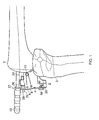
- FIG 1 shows a drill guide 2 in accordance with a first embodiment of the invention, wherein the drill guide is located in a knee joint between the tibia and the femur.
- the drill guide 2 comprises a body 4.
- the body 4 has a first drilling hole 6 and a second drilling hole 8 which each extend longitudinally through the body 4 (as shown in Figure 3 ).
- the first and second drilling holes 6, 8 are aligned at different angles which correspond to the required location of holes for the single peg femoral component or the two peg femoral component.
- the first and second drilling holes 6, 8 are shown angled at 0° and 10° respectively, however the angles may be chosen as 5° and 15° or other suitable angles for the femoral components which may be used.
- the body 4 of the drilling guide 2 is provided with protrusions 10, 12 on both the left lateral and right lateral side of the body 4.
- the distance from the end of one protrusion to the other is equal to the width of the femoral component and thus provides a means of aligning the drill guide 2 in the centre of the femoral condyle.
- the drill guide 2 may be supplied in different sizes which correspond to the size of the femoral component e.g. the width of the component and/or the radius of curvature of the component.
- the protrusions 10, 12 may be replaced with different sized protrusions to indicate the correct width of the component.
- the body 4 is provided with a fixed foot 14 and a movable foot 16.
- the movable foot 16 is releasably attached to the body 4 by a screw 18 or other such means which passes through a slot 19 in the body 4 and into the movable foot 16.
- the movable foot 16 is locked in position by tightening the screw 18 such that the section of the body 4 disposed between the head of the screw 18 and the movable foot 16 is held therebetween.
- the movable foot 16 is released by undoing the screw 18 sufficiently so that the body 4 is no longer held between the head of the screw 18 and the movable foot 16.
- the movable foot 16 is then free to translate toward or away from the fixed foot 14.
- the body 4 and movable foot 16 may be provided with an incremental locking means 20.
- the incremental locking means 20 allows the movable foot 16 to be translated and locked in predefined positions.
- the incremental locking means 20 may be provided with a scale for determining the position of the movable foot 16.
- the fixed foot 14 is narrow to allow reference off the posterior femoral condyle without interference from femoral osteophytes.
- the movable foot 16 has a leading edge which is curved in the plane of the movable foot 16. This allows the movable foot 16 and therefore the drill guide 2 to be angled relative to the vertical cut on the tibial plateau.
- the underside of the movable foot 16 is also curved along its length. This curvature allows the drill guide 2 to be rotated about the tibial plateau in the anteroposterior plane.
- the drill guide 2 further comprises an alignment tool 22 for aligning the body 4.
- the alignment tool 22 has a handle 23 and a bifurcated end, the bifurcated end having a first arm 25 and a second arm 26.
- the first arm 25 is received within a mounting hole 28 provided on the top of the body 4 of the drill guide 2.
- the drill guide 2 is provided with two mounting holes 28 for use of the drill guide 2 on a left or right knee.
- An intramedullary rod 24 is passed into the intramedullary canal of the patient, which provides a reference for the drill guide 2. At least an end portion of the intramedullary rod 24 is cannulated and the second arm 26 is received within the intramedullary rod 24.
- the second arm 26 may be cannulated so that the intramedullary rod 24 is received within the second arm 26.
- the first and second arms 25, 26 are pivotably mounted on the handle 23 of the alignment tool 22 such that the distance between the first and second arms 25, 26 may be altered.
- the mounting holes 28 are angled relative to the body 4, either to the left or right lateral side of the body 4 as shown in Figure 2 , to provide the correct alignment, preferably 7°, for the drill guide 2 relative to the intramedullary rod 24. Also the mounting holes 28 may be angled in the vertical plane relative to the body 4; preferably they are angled down by 5°, as shown in Figure 2 .
- the drill guide 2 is inserted into the operative wound of the patient, with the movable foot 16 aligned with the fixed foot 14.
- the movable foot 16 is then translated vertically such that the fixed foot 14 contacts the posterior femoral condyle and the movable foot 16 contacts the tibial plateau.
- the position of the movable foot 16 is determined by the amount of bone resected from the tibial plateau.
- the scale on the incremental locking means 20 may correspond to a setting on a previously used resection guide. This allows the surgeon to easily adjust the movable foot 16 to the correct position for the amount of bone resected from the tibial plateau so that the drill holes are correctly aligned on the distal femoral condyle.
- the alignment tool 22 is connected to both the body 4 and the intramedullary rod 24 by inserting the first arm 25 into the correct mounting hole 28 and by inserting the second arm 26 into the cannulated end of the intramedullary rod 24.
- the protrusions 10, 12 on the body 4 are then used to align the drill guide 2 in the centre of the femoral condyle.
- the pivotably mounted first and second arms 25, 26 allow the distance between the first and second arms 25, 26 to be altered. This allows the drill guide 2 to be moved laterally whilst maintaining the correct alignment with the intramedullary rod 24 in both the anteroposterior and transverse planes.
- the curvature of the underside of the movable foot 16 allows the drill guide to be rotated about the tibial plateau in the anteroposterior plane. This therefore enables the drill guide 2 to correctly align the drilling holes 6, 8 without the knee being in perfect 90° flexion.
- a drill 30 is passed through one of the first and second drilling holes 6, 8 and drilled into the distal femoral condyle.
- the drill 30 is drilled into the distal femoral condyle until a stop 32 on the drill 30 abuts the body 4 and prevents the drill 30 from drilling any deeper.
- the length of the first and second drilling holes 6, 8 and the length of the drill 30 therefore controls the depth of the hole.
- the hole may be used to mount a cutting guide and/or milling spigot for resection of the femoral condyle to the desired shape for the femoral component.
- the fixed foot may contact the tibial plateau and the movable foot may contact the posterior femoral condyle.
- first and second drilling holes 6, 8 may be replaced by a single drilling hole which is pivotably mounted in the body 4.
- the angle of the single drilling hole may be adjusted to correspond to the femoral component and locked in position by a locking mechanism.
- the locking mechanism and single drilling hole may be provided with an indexing mechanism which provides discrete angles for the single drilling hole.
- the present invention has been described in reference to a knee replacement; however the invention may be adapted to be used in other joints.
- the present invention provides a drill guide which does not require the use of feeler gauges and which has a direct connection to the intramedullary rod so as to simplify alignment of the drill guide.
- EP10781729.8 PCT/GB2010/002117 .
- the original claims of EP10781729.8 are presented as numbered statements below.
Abstract
Description
- The present invention relates to a drill guide particularly, but not exclusively, a femoral drill guide for use during a partial knee replacement.
- During knee arthroplasty, particularly a partial knee replacement, the joint is prepared by first resecting the tibial plateau. Following resection of the tibial plateau, one or more holes are then drilled into the femoral condyle to receive a cutting guide for resecting the condyle. Conventionally, a hole is made in the intramedullary canal of the femur, into which an intramedullary rod is inserted. The intramedullary rod acts as a reference for the drilling of the hole or holes which locate the cutting guide. These holes may also serve to locate the femoral component of the prosthetic following resection of the femoral condyle.
- The femoral component may comprise a single fixation peg or two fixation pegs which are received in holes in the femur. In addition or as an alternative, the femoral component may comprise one or more webs. The webs may be thin layers of material, which may extend between the pegs.
- A two peg component provides greater coverage (i.e. a larger degree of rotation) and may be selected where the patient's lifestyle is such that they are squatting regularly.
- As described previously, the intramedullary rod is used as a reference for locating the hole(s) for receiving the cutting guide. A drill guide may be used to reference from the intramedullary rod in order to properly locate the cutting guide. Existing drill guides require the surgeon to align the drill guide with the intramedullary rod in various planes so that the guide hole is placed in the correct position on the femur.
- In a known technique, a tibial template is placed on the resected tibial plateau and the drill guide inserted into the operative wound. A feeler gauge is then inserted in between the tibial template and the drill guide. Due to this layering of components there is a stack up in the tolerances of each component.
- It is desirable to provide a drill guide which has a simplified alignment process.
- According to a first aspect of the invention, there is provided a drill guide comprising: a body comprising a hole extending therethrough for guiding a drill; and an alignment tool, the alignment tool being operable to connect the body to an intramedullary rod, such that the orientation of the body is fixable with respect to the intramedullary rod in an anteroposterior plane and in a transverse plane.
- According to a second aspect of the invention, there is provided a drill guide comprising: a body comprising a hole extending therethrough for guiding a drill; wherein the body comprises a fixed foot and a movable foot which are receivable within a joint; wherein the movable foot is releasably attached to the body and, when in a released state, the movable foot is translatable with respect to the fixed foot, such that the fixed foot contacts a first bone of the joint and the movable foot contacts a second bone of the joint.
- According to a third aspect of the invention, there is provided a drill guide comprising: a body and a tubular element, the tubular element having a hole extending therethrough for guiding a drill; wherein the tubular element is pivotably mounted with respect to the body such that the angle of the tubular element with respect to the body is adjustable.
- Any of the above aspects of the invention may be combined with one or more of the other aspects of the invention and/or one or more of the optional features set out below.
- The alignment tool may comprise a first arm and a second arm, the first arm being operable to connect the alignment tool to the body and the second arm being operable to connect the alignment tool to the intramedullary rod.
- The first and second arms may be pivotably connected to one another such that the distance between the first and second arms can be altered.
- The intramedullary rod may be cannulated and the second arm is received within the intramedullary rod.
- The body may have a mounting hole for receiving the alignment tool.
- The mounting hole may be angled to the left or right lateral side of the body.
- The mounting hole may be angled to the left or right lateral side of the body by 7°.
- The mounting hole may be angled in the vertical plane relative to the body.
- The mounting hole may be angled down by 5°.
- The alignment tool may comprise a handle.
- The movable foot may be releasably attached to the body by a screw which passes through a slot in the body and into the movable foot.
- The movable foot may be locked in position by tightening the screw such that a section of the body disposed between a head of the screw and the movable foot is held therebetween.
- The drill guide may further comprise an incremental locking means for locking the movable foot in predefined positions.
- A leading edge of the movable foot may be curved in the plane of the movable foot.
- An underside of the movable foot may be curved along its length.
- The hole may comprise first and second holes, which extend through the body at different angles.
- The first and second holes may be angled at 0° and 10° respectively or 5° and 15° respectively.
- The body may further comprise a protrusion on a left lateral side of the body and a protrusion on a right lateral side of the body.
- The distance between the protrusions may be equal to a width of a femoral component.
- The drill guide may further comprise a locking mechanism for locking the angle of the tubular element with respect to the body.
- The drill guide may further comprise an indexing mechanism for positioning the tubular element in predefined angles with respect to the body.
- The tubular element may be translatable with respect to the body.
- The tubular element may be translatable toward the top or bottom of the body.
- For a better understanding of the present invention, and to show more clearly how it may be carried into effect, reference will now be made, by way of example, to the accompanying drawings, in which:-
-
Figure 1 is a side view of a drill guide in accordance with the invention, wherein the drill guide is in use; -
Figure 2 is a top view of the drill guide; -
Figure 3 is a front view of the drill guide; and -
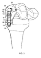
Figure 4 is a second side view of the drill guide inFigure 1 during drilling. -
Figure 1 shows adrill guide 2 in accordance with a first embodiment of the invention, wherein the drill guide is located in a knee joint between the tibia and the femur. Thedrill guide 2 comprises abody 4. Thebody 4 has afirst drilling hole 6 and asecond drilling hole 8 which each extend longitudinally through the body 4 (as shown inFigure 3 ). The first andsecond drilling holes second drilling holes - The
body 4 of thedrilling guide 2 is provided withprotrusions body 4. The distance from the end of one protrusion to the other is equal to the width of the femoral component and thus provides a means of aligning thedrill guide 2 in the centre of the femoral condyle. - The
drill guide 2 may be supplied in different sizes which correspond to the size of the femoral component e.g. the width of the component and/or the radius of curvature of the component. Alternatively, theprotrusions - The
body 4 is provided with a fixedfoot 14 and amovable foot 16. Themovable foot 16 is releasably attached to thebody 4 by ascrew 18 or other such means which passes through aslot 19 in thebody 4 and into themovable foot 16. Themovable foot 16 is locked in position by tightening thescrew 18 such that the section of thebody 4 disposed between the head of thescrew 18 and themovable foot 16 is held therebetween. Themovable foot 16 is released by undoing thescrew 18 sufficiently so that thebody 4 is no longer held between the head of thescrew 18 and themovable foot 16. Themovable foot 16 is then free to translate toward or away from the fixedfoot 14. - The
body 4 andmovable foot 16 may be provided with an incremental locking means 20. The incremental locking means 20 allows themovable foot 16 to be translated and locked in predefined positions. The incremental locking means 20 may be provided with a scale for determining the position of themovable foot 16. - The fixed
foot 14 is narrow to allow reference off the posterior femoral condyle without interference from femoral osteophytes. - The
movable foot 16 has a leading edge which is curved in the plane of themovable foot 16. This allows themovable foot 16 and therefore thedrill guide 2 to be angled relative to the vertical cut on the tibial plateau. The underside of themovable foot 16 is also curved along its length. This curvature allows thedrill guide 2 to be rotated about the tibial plateau in the anteroposterior plane. - The
drill guide 2 further comprises analignment tool 22 for aligning thebody 4. Thealignment tool 22 has ahandle 23 and a bifurcated end, the bifurcated end having afirst arm 25 and asecond arm 26. Thefirst arm 25 is received within a mountinghole 28 provided on the top of thebody 4 of thedrill guide 2. Thedrill guide 2 is provided with two mountingholes 28 for use of thedrill guide 2 on a left or right knee. Anintramedullary rod 24 is passed into the intramedullary canal of the patient, which provides a reference for thedrill guide 2. At least an end portion of theintramedullary rod 24 is cannulated and thesecond arm 26 is received within theintramedullary rod 24. Alternatively, thesecond arm 26 may be cannulated so that theintramedullary rod 24 is received within thesecond arm 26. - The first and
second arms handle 23 of thealignment tool 22 such that the distance between the first andsecond arms - The mounting holes 28 are angled relative to the
body 4, either to the left or right lateral side of thebody 4 as shown inFigure 2 , to provide the correct alignment, preferably 7°, for thedrill guide 2 relative to theintramedullary rod 24. Also the mountingholes 28 may be angled in the vertical plane relative to thebody 4; preferably they are angled down by 5°, as shown inFigure 2 . - In use, following resection of the tibial plateau, the
drill guide 2 is inserted into the operative wound of the patient, with themovable foot 16 aligned with the fixedfoot 14. Themovable foot 16 is then translated vertically such that the fixedfoot 14 contacts the posterior femoral condyle and themovable foot 16 contacts the tibial plateau. - The position of the
movable foot 16 is determined by the amount of bone resected from the tibial plateau. The scale on the incremental locking means 20 may correspond to a setting on a previously used resection guide. This allows the surgeon to easily adjust themovable foot 16 to the correct position for the amount of bone resected from the tibial plateau so that the drill holes are correctly aligned on the distal femoral condyle. - The
alignment tool 22 is connected to both thebody 4 and theintramedullary rod 24 by inserting thefirst arm 25 into the correct mountinghole 28 and by inserting thesecond arm 26 into the cannulated end of theintramedullary rod 24. - The
protrusions body 4 are then used to align thedrill guide 2 in the centre of the femoral condyle. The pivotably mounted first andsecond arms second arms drill guide 2 to be moved laterally whilst maintaining the correct alignment with theintramedullary rod 24 in both the anteroposterior and transverse planes. - As mentioned previously, the curvature of the underside of the
movable foot 16 allows the drill guide to be rotated about the tibial plateau in the anteroposterior plane. This therefore enables thedrill guide 2 to correctly align the drilling holes 6, 8 without the knee being in perfect 90° flexion. - As shown in
Figure 4 , once thedrill guide 2 is correctly aligned adrill 30 is passed through one of the first andsecond drilling holes drill 30 is drilled into the distal femoral condyle until astop 32 on thedrill 30 abuts thebody 4 and prevents thedrill 30 from drilling any deeper. The length of the first andsecond drilling holes drill 30 therefore controls the depth of the hole. - Following drilling, the hole may be used to mount a cutting guide and/or milling spigot for resection of the femoral condyle to the desired shape for the femoral component.
- In an alternative embodiment of the invention, the fixed foot may contact the tibial plateau and the movable foot may contact the posterior femoral condyle.
- In another embodiment of the invention, the first and
second drilling holes body 4. By virtue of this pivotable mounting, the angle of the single drilling hole may be adjusted to correspond to the femoral component and locked in position by a locking mechanism. The locking mechanism and single drilling hole may be provided with an indexing mechanism which provides discrete angles for the single drilling hole. - The present invention has been described in reference to a knee replacement; however the invention may be adapted to be used in other joints.
- The present invention provides a drill guide which does not require the use of feeler gauges and which has a direct connection to the intramedullary rod so as to simplify alignment of the drill guide.
- The present application is a divisional application of
EP10781729.8 PCT/GB2010/002117 EP10781729.8 - Statement 1. A drill guide comprising:
- a body comprising a hole extending therethrough for guiding a drill; and
- an alignment tool, the alignment tool being operable to connect the body to an intramedullary rod, such that the orientation of the body is fixable with respect to the intramedullary rod in an anteroposterior plane and in a transverse plane.
-
Statement 2. A drill guide according to statement 1, wherein the body comprises a fixed foot and a movable foot which are receivable within a joint;
wherein the movable foot is releasably attached to the body and, when in a released state, the movable foot is translatable with respect to the fixed foot, such that the fixed foot contacts a first bone of the joint and the movable foot contacts a second bone of the joint. -
Statement 3. A drill guide according tostatement 1 or 2, wherein the alignment tool comprises a first arm and a second arm, the first arm being operable to connect the alignment tool to the body and the second arm being operable to connect the alignment tool to the intramedullary rod. -
Statement 4. A drill guide according tostatement 3, wherein the first and second arms are pivotably connected to one another such that the distance between the first and second arms can be altered. -
Statement 5. A drill guide according tostatement -
Statement 6. A drill guide according to any preceding statement, wherein the body has a mounting hole for receiving the alignment tool. - Statement 7. A drill guide according to
statement 6, wherein the mounting hole is angled to the left or right lateral side of the body. -
Statement 8. A drill guide according to statement 7, wherein the mounting hole is angled to the left or right lateral side of the body by 7°. - Statement 9. A drill guide according to any one of
statements 6 to 8, wherein the mounting hole is angled in the vertical plane relative to the body. -
Statement 10. A drill guide according to statement 9, wherein the mounting hole is angled down by 5°. - Statement 11. A drill guide according to any one of the preceding statements, wherein the alignment tool comprises a handle.
-
Statement 12. A drill guide according tostatement 2 or any one ofstatements 3 to 11 when dependent onstatement 2, wherein the movable foot is releasably attached to the body by a screw which passes through a slot in the body and into the movable foot. - Statement 13. A drill guide according to
statement 12, wherein the movable foot is locked in position by tightening the screw such that a section of the body disposed between a head of the screw and the movable foot is held therebetween. -
Statement 14. A drill guide according tostatement statements 3 to 11 when dependent onstatement 2, further comprising an incremental locking means for locking the movable foot in predefined positions. - Statement 15. A drill guide according to
statement 2 or any one ofstatements 12 to 14 or any one ofstatements 3 to 11 when dependent onstatement 2, wherein a leading edge of the movable foot is curved in the plane of the movable foot. -
Statement 16. A drill guide according tostatement 2 or any one ofstatements 12 to 15 or any one ofstatements 3 to 11 when dependent onstatement 2, wherein an underside of the movable foot is curved along its length. - Statement 17. A drill guide according to any one of the preceding statements, wherein the hole is defined by a tubular element which is pivotably mounted with respect to the body such that the angle of the tubular element with respect to the body is adjustable.
-
Statement 18. A drill guide according to any one of the preceding statements, wherein the hole comprises first and second holes, which extend through the body at different angles. -
Statement 19. A drill guide according tostatement 18, wherein the first and second holes are angled at 0° and 10° respectively or 5° and 15° respectively. -
Statement 20. A drill guide according to any one of the preceding statements, wherein the body further comprises a protrusion on a left lateral side of the body and a protrusion on a right lateral side of the body. - Statement 21. A drill guide according to
statement 20, wherein the distance between the protrusions is equal to a width of a femoral component. -
Statement 22. A drill guide comprising: a body comprising a hole extending therethrough for guiding a drill;
wherein the body comprises a fixed foot and a movable foot which are receivable within a joint;
wherein the movable foot is releasably attached to the body and, when in a released state, the movable foot is translatable with respect to the fixed foot, such that the fixed foot contacts a first bone of the joint and the movable foot contacts a second bone of the joint. -
Statement 23. A drill guide according tostatement 22, wherein the movable foot is releasably attached to the body by a screw which passes through a slot in the body and into the movable foot. -
Statement 24. A drill guide according tostatement 23, wherein the movable foot is locked in position by tightening the screw such that a section of the body disposed between a head of the screw and the movable foot is held therebetween. -
Statement 25. A drill guide according to any one ofstatements 22 to 24, further comprising an incremental locking means for locking the movable foot in predefined positions. -
Statement 26. A drill guide according to any one ofstatements 22 to 25, wherein a leading edge of the movable foot is curved in the plane of the movable foot. - Statement 27. A drill guide according to any one of
statements 22 to 26, wherein an underside of the movable is curved along its length. -
Statement 28. A drill guide comprising:- a body and a tubular element, the tubular element having a hole extending therethrough for guiding a drill; wherein the tubular element is pivotably mounted with respect to the body such that the angle of the tubular element with respect to the body is adjustable.
- Statement 29. A drill guide according to
statement 28, further comprising a locking mechanism for locking the angle of the tubular element with respect to the body. -
Statement 30. A drill guide according tostatement 28 or 29, further comprising an indexing mechanism for positioning the tubular element in predefined angles with respect to the body. - Statement 31. A drill guide according to any one of
statements 28 to 30, wherein the tubular element is translatable with respect to the body. -
Statement 32. A drill guide according to statement 31, wherein the tubular element is translatable toward the top or bottom of the body.
Claims (15)
- A drill guide (2) comprising:a body (4) comprising a hole (6,8) extending therethrough for guiding a drill;an intramedullary rod (24); andan alignment tool (22), the alignment tool (22) being operable to connect the body to the intramedullary rod (24), such that the orientation of the body (4) is fixable with respect to the intramedullary rod (24) in an anteroposterior plane and in a transverse plane;wherein the alignment tool (22) comprises a first arm (25) and a second arm (26), the first arm (25) being operable to connect the alignment tool (22) to the body (4) and the second arm (26) being operable to connect the alignment tool (22) to the intramedullary rod (24);wherein the first and second arms (25, 26) are pivotably connected to one another such that the distance between the first and second arms (25, 26) can be altered, andwherein the first and second arms (25, 26) are configured such that, when the distance between the first and second arms (25, 26) is altered, the drill guide (2) moves laterally whilst maintaining the correct alignment with the intramedullary rod (24) in both the anteroposterior and transverse planes.
- A drill guide (2) as claimed in claim 1, wherein one of the intramedullary rod (24) and the second arm (26) is cannulated and the other of the intramedullary rod (24) and the second arm (26) is received within the one of the intramedullary rod (24) and the second arm (26).
- A drill guide (2) as claimed in any of the preceding claims, wherein the body (24) has a mounting hole (28) for receiving the alignment tool (22).
- A drill guide (2) as claimed in claim 3, wherein the mounting hole (28) is angled to the left or right lateral side of the body (4).
- A drill guide (2) as claimed in claim 4, wherein the mounting hole (28) is angled to the left or right lateral side of the body (4) by 7°.
- A drill guide (2) as claimed in any of claims 3 to 5, wherein the mounting hole (28) is angled in the vertical plane relative to the body (4).
- A drill guide (2) as claimed in claim 6, wherein the mounting hole (28) is angled in the vertical plane relative to the body (4) by 5° downwards.
- A drill guide (2) as claimed in any of the preceding claims, wherein the alignment tool (22) comprises a handle (23).
- A drill guide (2) as claimed in claim 8, wherein the first and second arms (25, 26) are pivotably mounted on the handle (23).
- A drill guide (2) as claimed in any of the preceding claims, wherein the hole (6, 8) is defined by a tubular element which is pivotably mounted with respect to the body (4) such that the angle of the tubular element with respect to the body (4) is adjustable.
- A drill guide (2) as claimed in any of the preceding claims, wherein the hole (6, 8) comprises first and second holes (6, 8) which extend through the body (4) at different angles.
- A drill guide (2) as claimed in claim 11, wherein the first and second holes (6, 8) extend through the body (4) at 0° and 10° respectively.
- A drill guide (2) as claimed in claim 11, wherein the first and second holes (6, 8) extend through the body (4) at 5° and 15° respectively.
- A drill guide (2) as claimed in any of the preceding claims, wherein the body (4) further comprises a protrusion (10) on a left lateral side of the body (4) and a protrusion (12) on a right lateral side of the body (4).
- A drill guide (2) as claimed in claim 14, wherein the distance between the protrusions is equal to a width of a femoral component.
Applications Claiming Priority (3)
| Application Number | Priority Date | Filing Date | Title |
|---|---|---|---|
| GB0920225A GB2475491A (en) | 2009-11-18 | 2009-11-18 | Alignment tool for a femoral drill guide |
| EP10781729.8A EP2501302B1 (en) | 2009-11-18 | 2010-11-17 | A drill guide |
| PCT/GB2010/002117 WO2011061489A1 (en) | 2009-11-18 | 2010-11-17 | A drill guide |
Related Parent Applications (2)
| Application Number | Title | Priority Date | Filing Date |
|---|---|---|---|
| EP10781729.8A Division EP2501302B1 (en) | 2009-11-18 | 2010-11-17 | A drill guide |
| EP10781729.8A Division-Into EP2501302B1 (en) | 2009-11-18 | 2010-11-17 | A drill guide |
Publications (2)
| Publication Number | Publication Date |
|---|---|
| EP2896375A1 true EP2896375A1 (en) | 2015-07-22 |
| EP2896375B1 EP2896375B1 (en) | 2020-04-15 |
Family
ID=41565500
Family Applications (2)
| Application Number | Title | Priority Date | Filing Date |
|---|---|---|---|
| EP15152599.5A Active EP2896375B1 (en) | 2009-11-18 | 2010-11-17 | A drill guide |
| EP10781729.8A Active EP2501302B1 (en) | 2009-11-18 | 2010-11-17 | A drill guide |
Family Applications After (1)
| Application Number | Title | Priority Date | Filing Date |
|---|---|---|---|
| EP10781729.8A Active EP2501302B1 (en) | 2009-11-18 | 2010-11-17 | A drill guide |
Country Status (8)
| Country | Link |
|---|---|
| US (1) | US9028503B2 (en) |
| EP (2) | EP2896375B1 (en) |
| JP (1) | JP5750117B2 (en) |
| KR (1) | KR101757010B1 (en) |
| AU (1) | AU2010320719B2 (en) |
| CA (1) | CA2781006C (en) |
| GB (1) | GB2475491A (en) |
| WO (1) | WO2011061489A1 (en) |
Families Citing this family (11)
| Publication number | Priority date | Publication date | Assignee | Title |
|---|---|---|---|---|
| GB2482702A (en) | 2010-08-11 | 2012-02-15 | Biomet Uk Healthcare Ltd | Ligament balancer |
| US8672946B2 (en) | 2011-02-11 | 2014-03-18 | Biomet Manfacturing, LLC | Method and apparatus for performing knee arthroplasty |
| US9241784B2 (en) | 2011-07-08 | 2016-01-26 | Smith & Nephew, Inc. | Soft tissue reconstruction |
| US8882834B2 (en) | 2011-07-08 | 2014-11-11 | Smith & Nephew, Inc. | Soft tissue repair |
| US9955963B2 (en) | 2011-07-08 | 2018-05-01 | Smith & Nephew, Inc. | Soft tissue repair |
| US10342529B2 (en) | 2011-07-08 | 2019-07-09 | Smith & Nephew, Inc. | Osteotomy guide and method |
| US9662105B2 (en) | 2011-07-08 | 2017-05-30 | Smith & Nephew, Inc. | Suture passer and method |
| US9907558B2 (en) | 2011-07-08 | 2018-03-06 | Smith & Nephew, Inc. | Osteotomy guide and method |
| US9357997B2 (en) | 2011-07-08 | 2016-06-07 | Smith & Nephew, Inc. | Suture passer and method |
| GB2506616B (en) * | 2012-10-03 | 2018-12-05 | Corin Ltd | Leg alignment apparatus and method |
| KR102053600B1 (en) * | 2017-07-25 | 2019-12-11 | 주식회사 코렌텍 | Patient-Specific Artificial Shoulder Joint Surgical Instruments |
Citations (3)
| Publication number | Priority date | Publication date | Assignee | Title |
|---|---|---|---|---|
| AT410282B (en) * | 2000-09-01 | 2003-03-25 | Ender Hans Georg | Bone-peg for fixing split fracture of joint bone head of humerus, has hole which is provided at bone-peg edge portion for inserting screw to hold fracture split of joint bone head |
| US20040153066A1 (en) * | 2003-02-03 | 2004-08-05 | Coon Thomas M. | Apparatus for knee surgery and method of use |
| EP1479350A2 (en) * | 1996-04-25 | 2004-11-24 | Nuvana Medical Innovations, L.L.C. | Intermedullary rod apparatus for repairing proximal humerus fractures |
Family Cites Families (32)
| Publication number | Priority date | Publication date | Assignee | Title |
|---|---|---|---|---|
| US2666430A (en) * | 1949-05-31 | 1954-01-19 | Gispert Humberto Altamirano | Hip nail aiming and guiding device |
| US2697433A (en) * | 1951-12-04 | 1954-12-21 | Max A Zehnder | Device for accurately positioning and guiding guide wires used in the nailing of thefemoral neck |
| US4566448A (en) | 1983-03-07 | 1986-01-28 | Rohr Jr William L | Ligament tensor and distal femoral resector guide |
| EP0315338B1 (en) * | 1987-10-21 | 1993-02-03 | SMITH & NEPHEW RICHARDS, INC. | Surgical instrument |
| US5385567A (en) * | 1990-09-07 | 1995-01-31 | Goble; E. Marlowe | Sight barrel arthroscopic instrument |
| EP0613658B1 (en) * | 1993-03-05 | 2001-09-12 | Sulzer Orthopädie AG | Apparatus for determining the course of drill-holes in bone |
| DE9308276U1 (en) | 1993-06-02 | 1993-08-05 | Weber, Gerhard, 78727 Oberndorf, De | |
| US5423827A (en) * | 1994-06-02 | 1995-06-13 | Intermedics Orthopedics, Inc. | Surgical jig for femoral knee prosthesis |
| IT1268313B1 (en) * | 1994-07-28 | 1997-02-27 | Orthofix Srl | MECHANICAL EQUIPMENT FOR CENTERING BLIND HOLES FOR BONE SCREWS OF INTRAMIDOLLAR NAILS |
| DE29504857U1 (en) * | 1995-03-22 | 1995-05-18 | Aesculap Ag | Drilling jig for surgical drilling tools |
| GB9611074D0 (en) * | 1996-05-28 | 1996-07-31 | Howmedica | Surgical apparatus |
| EP1095626B1 (en) * | 1999-11-01 | 2016-02-24 | Zimmer GmbH | Intramedullary nail for the radius |
| AU2001250538A1 (en) * | 2000-04-27 | 2001-11-20 | Finsbury (Development) Limited | Surgical tool |
| DE50110247D1 (en) * | 2001-04-27 | 2006-08-03 | Zimmer Gmbh | Drill lower for fixing the axis of a femoral head prosthesis |
| EP1260188B1 (en) * | 2001-05-25 | 2014-09-17 | Zimmer GmbH | Femoral bone nail for implantation in the knee |
| FR2829376A1 (en) * | 2001-09-07 | 2003-03-14 | Bertrand Bergue | Knee joint arthroplasty cutting line marker has femoral and tibial instruments with assembly system |
| PT1480582E (en) | 2002-02-14 | 2012-10-02 | Biomet Spain Orthopaedics S L | Patello-femoral joint replacement |
| DE10215358B4 (en) * | 2002-04-08 | 2007-03-08 | Mathys Medizinaltechnik Ag | Ligament tensioning device with cutting gauge |
| US20040220583A1 (en) * | 2003-02-04 | 2004-11-04 | Zimmer Technology, Inc. | Instrumentation for total knee arthroplasty, and methods of performing same |
| DE10309493A1 (en) * | 2003-02-26 | 2004-09-16 | Aesculap Ag & Co. Kg | Positioning and holder device for surgical tool guide, e.g. for knee operations, has fastener rotatably mounted in off centre position on platform |
| US7641659B2 (en) * | 2003-03-13 | 2010-01-05 | Zimmer Spine, Inc. | Spinal access instrument |
| EP1470786B1 (en) * | 2003-04-25 | 2005-10-05 | Zimmer GmbH | Device for preparation of a femoral condyle |
| US7481814B1 (en) * | 2003-07-28 | 2009-01-27 | Biomet Manufacturing Corporation | Method and apparatus for use of a mill or reamer |
| GB0404347D0 (en) * | 2004-02-27 | 2004-03-31 | Depuy Int Ltd | A drill guide assembly |
| WO2005084559A1 (en) * | 2004-03-01 | 2005-09-15 | Depuy International Limited | An alignment instrument for use with an intramedullary nail |
| US20060064104A1 (en) | 2004-09-09 | 2006-03-23 | Kana Richard J | Translating surgical mount |
| DE102004063977A1 (en) * | 2004-10-19 | 2006-06-22 | Mathys Ag Bettlach | Ligament Tension Device, Cutting Guide and Osteotomy Technique |
| GB2423021A (en) * | 2005-02-15 | 2006-08-16 | Biomet Uk Ltd | A surgical guide jig with an expanding spherical joint |
| US20070100346A1 (en) * | 2005-10-27 | 2007-05-03 | Wyss Joseph G | Support for locating instrument guides |
| US8685034B2 (en) * | 2006-08-10 | 2014-04-01 | Stryker Trauma Gmbh | Distal targeting device |
| WO2008064211A1 (en) * | 2006-11-21 | 2008-05-29 | Smith & Nephew, Inc. | Variable angle drill guide |
| US8771283B2 (en) | 2007-12-17 | 2014-07-08 | Wright Medical Technology, Inc. | Guide assembly for intramedullary fixation and method of using the same |
-
2009
- 2009-11-18 GB GB0920225A patent/GB2475491A/en not_active Withdrawn
-
2010
- 2010-11-17 WO PCT/GB2010/002117 patent/WO2011061489A1/en active Application Filing
- 2010-11-17 EP EP15152599.5A patent/EP2896375B1/en active Active
- 2010-11-17 CA CA2781006A patent/CA2781006C/en active Active
- 2010-11-17 AU AU2010320719A patent/AU2010320719B2/en active Active
- 2010-11-17 US US13/510,480 patent/US9028503B2/en active Active
- 2010-11-17 JP JP2012539404A patent/JP5750117B2/en active Active
- 2010-11-17 EP EP10781729.8A patent/EP2501302B1/en active Active
- 2010-11-17 KR KR1020127015320A patent/KR101757010B1/en active IP Right Grant
Patent Citations (3)
| Publication number | Priority date | Publication date | Assignee | Title |
|---|---|---|---|---|
| EP1479350A2 (en) * | 1996-04-25 | 2004-11-24 | Nuvana Medical Innovations, L.L.C. | Intermedullary rod apparatus for repairing proximal humerus fractures |
| AT410282B (en) * | 2000-09-01 | 2003-03-25 | Ender Hans Georg | Bone-peg for fixing split fracture of joint bone head of humerus, has hole which is provided at bone-peg edge portion for inserting screw to hold fracture split of joint bone head |
| US20040153066A1 (en) * | 2003-02-03 | 2004-08-05 | Coon Thomas M. | Apparatus for knee surgery and method of use |
Also Published As
| Publication number | Publication date |
|---|---|
| EP2896375B1 (en) | 2020-04-15 |
| JP2013511316A (en) | 2013-04-04 |
| EP2501302B1 (en) | 2015-11-11 |
| JP5750117B2 (en) | 2015-07-15 |
| US20120323249A1 (en) | 2012-12-20 |
| WO2011061489A1 (en) | 2011-05-26 |
| AU2010320719A1 (en) | 2012-06-07 |
| AU2010320719B2 (en) | 2015-01-22 |
| EP2501302A1 (en) | 2012-09-26 |
| KR101757010B1 (en) | 2017-07-11 |
| GB0920225D0 (en) | 2010-01-06 |
| CA2781006C (en) | 2018-07-24 |
| KR20120132468A (en) | 2012-12-05 |
| GB2475491A (en) | 2011-05-25 |
| US9028503B2 (en) | 2015-05-12 |
| CA2781006A1 (en) | 2011-05-26 |
Similar Documents
| Publication | Publication Date | Title |
|---|---|---|
| EP2896375B1 (en) | A drill guide | |
| EP1095624B1 (en) | Femoral milling instrumentation for use in total knee arthroplasty | |
| EP2775942B1 (en) | A bone sizing guide | |
| US6033410A (en) | Orthopaedic instrumentation | |
| EP2407115B1 (en) | Instrumentation for use in a patellofemoral arthroplasty procedure | |
| US8828012B2 (en) | Anterior cortex referencing extramedullary femoral cut guide | |
| US7621920B2 (en) | Adjustable cut guide | |
| EP2953559B1 (en) | Total knee arthroplasty systems | |
| EP2568890B1 (en) | A femoral sizing guide | |
| EP2568889B1 (en) | A surgical instrument | |
| US20010001121A1 (en) | Methods and tools for femoral intermedullary revision surgery | |
| US20220192686A1 (en) | Resection guides, sweeping reamers, and methods for use in total ankle replacement | |
| WO1997030640A9 (en) | Distal femoral cutting guide apparatus | |
| WO1997030640A1 (en) | Distal femoral cutting guide apparatus | |
| WO2007113534A1 (en) | Orthopaedic cutting guide instrument | |
| US6629978B2 (en) | Valgus adapter | |
| US8043294B2 (en) | Reference mark adjustment mechanism for a femoral caliper and method of using the same | |
| EP1833386B1 (en) | A drill guide assembly | |
| AU2014268275A1 (en) | A Drill Guide |
Legal Events
| Date | Code | Title | Description |
|---|---|---|---|
| PUAI | Public reference made under article 153(3) epc to a published international application that has entered the european phase |
Free format text: ORIGINAL CODE: 0009012 |
|
| 17P | Request for examination filed |
Effective date: 20150127 |
|
| AC | Divisional application: reference to earlier application |
Ref document number: 2501302 Country of ref document: EP Kind code of ref document: P |
|
| AK | Designated contracting states |
Kind code of ref document: A1 Designated state(s): AL AT BE BG CH CY CZ DE DK EE ES FI FR GB GR HR HU IE IS IT LI LT LU LV MC MK MT NL NO PL PT RO RS SE SI SK SM TR |
|
| 17P | Request for examination filed |
Effective date: 20160121 |
|
| RBV | Designated contracting states (corrected) |
Designated state(s): AL AT BE BG CH CY CZ DE DK EE ES FI FR GB GR HR HU IE IS IT LI LT LU LV MC MK MT NL NO PL PT RO RS SE SI SK SM TR |
|
| 17Q | First examination report despatched |
Effective date: 20160523 |
|
| STAA | Information on the status of an ep patent application or granted ep patent |
Free format text: STATUS: EXAMINATION IS IN PROGRESS |
|
| GRAP | Despatch of communication of intention to grant a patent |
Free format text: ORIGINAL CODE: EPIDOSNIGR1 |
|
| STAA | Information on the status of an ep patent application or granted ep patent |
Free format text: STATUS: GRANT OF PATENT IS INTENDED |
|
| RAP1 | Party data changed (applicant data changed or rights of an application transferred) |
Owner name: MURRAY, DAVID WYCLIFFE Owner name: HUNSLEY, COLIN Owner name: OXFORD JOINT ANALYSIS LTD. Owner name: BIOMET UK LIMITED |
|
| INTG | Intention to grant announced |
Effective date: 20191029 |
|
| RAP1 | Party data changed (applicant data changed or rights of an application transferred) |
Owner name: COLIN HUNSLEY, ACTING AS EXECUTOR FOR THE ESTATE O Owner name: BIOMET UK LIMITED Owner name: OXFORD JOINT ANALYSIS LTD. Owner name: MURRAY, DAVID WYCLIFFE |
|
| GRAS | Grant fee paid |
Free format text: ORIGINAL CODE: EPIDOSNIGR3 |
|
| GRAA | (expected) grant |
Free format text: ORIGINAL CODE: 0009210 |
|
| STAA | Information on the status of an ep patent application or granted ep patent |
Free format text: STATUS: THE PATENT HAS BEEN GRANTED |
|
| AC | Divisional application: reference to earlier application |
Ref document number: 2501302 Country of ref document: EP Kind code of ref document: P |
|
| AK | Designated contracting states |
Kind code of ref document: B1 Designated state(s): AL AT BE BG CH CY CZ DE DK EE ES FI FR GB GR HR HU IE IS IT LI LT LU LV MC MK MT NL NO PL PT RO RS SE SI SK SM TR |
|
| REG | Reference to a national code |
Ref country code: CH Ref legal event code: EP |
|
| REG | Reference to a national code |
Ref country code: DE Ref legal event code: R096 Ref document number: 602010063961 Country of ref document: DE |
|
| REG | Reference to a national code |
Ref country code: IE Ref legal event code: FG4D |
|
| REG | Reference to a national code |
Ref country code: AT Ref legal event code: REF Ref document number: 1256378 Country of ref document: AT Kind code of ref document: T Effective date: 20200515 |
|
| REG | Reference to a national code |
Ref country code: CH Ref legal event code: NV Representative=s name: MICHELI AND CIE SA, CH |
|
| REG | Reference to a national code |
Ref country code: NL Ref legal event code: MP Effective date: 20200415 |
|
| REG | Reference to a national code |
Ref country code: LT Ref legal event code: MG4D |
|
| REG | Reference to a national code |
Ref country code: DE Ref legal event code: R082 Ref document number: 602010063961 Country of ref document: DE Representative=s name: VENNER SHIPLEY GERMANY LLP, DE Ref country code: DE Ref legal event code: R082 Ref document number: 602010063961 Country of ref document: DE Representative=s name: VENNER SHIPLEY LLP, DE |
|
| PG25 | Lapsed in a contracting state [announced via postgrant information from national office to epo] |
Ref country code: SE Free format text: LAPSE BECAUSE OF FAILURE TO SUBMIT A TRANSLATION OF THE DESCRIPTION OR TO PAY THE FEE WITHIN THE PRESCRIBED TIME-LIMIT Effective date: 20200415 Ref country code: FI Free format text: LAPSE BECAUSE OF FAILURE TO SUBMIT A TRANSLATION OF THE DESCRIPTION OR TO PAY THE FEE WITHIN THE PRESCRIBED TIME-LIMIT Effective date: 20200415 Ref country code: IS Free format text: LAPSE BECAUSE OF FAILURE TO SUBMIT A TRANSLATION OF THE DESCRIPTION OR TO PAY THE FEE WITHIN THE PRESCRIBED TIME-LIMIT Effective date: 20200815 Ref country code: NO Free format text: LAPSE BECAUSE OF FAILURE TO SUBMIT A TRANSLATION OF THE DESCRIPTION OR TO PAY THE FEE WITHIN THE PRESCRIBED TIME-LIMIT Effective date: 20200715 Ref country code: GR Free format text: LAPSE BECAUSE OF FAILURE TO SUBMIT A TRANSLATION OF THE DESCRIPTION OR TO PAY THE FEE WITHIN THE PRESCRIBED TIME-LIMIT Effective date: 20200716 Ref country code: LT Free format text: LAPSE BECAUSE OF FAILURE TO SUBMIT A TRANSLATION OF THE DESCRIPTION OR TO PAY THE FEE WITHIN THE PRESCRIBED TIME-LIMIT Effective date: 20200415 Ref country code: PT Free format text: LAPSE BECAUSE OF FAILURE TO SUBMIT A TRANSLATION OF THE DESCRIPTION OR TO PAY THE FEE WITHIN THE PRESCRIBED TIME-LIMIT Effective date: 20200817 Ref country code: NL Free format text: LAPSE BECAUSE OF FAILURE TO SUBMIT A TRANSLATION OF THE DESCRIPTION OR TO PAY THE FEE WITHIN THE PRESCRIBED TIME-LIMIT Effective date: 20200415 |
|
| REG | Reference to a national code |
Ref country code: AT Ref legal event code: MK05 Ref document number: 1256378 Country of ref document: AT Kind code of ref document: T Effective date: 20200415 |
|
| PG25 | Lapsed in a contracting state [announced via postgrant information from national office to epo] |
Ref country code: LV Free format text: LAPSE BECAUSE OF FAILURE TO SUBMIT A TRANSLATION OF THE DESCRIPTION OR TO PAY THE FEE WITHIN THE PRESCRIBED TIME-LIMIT Effective date: 20200415 Ref country code: BG Free format text: LAPSE BECAUSE OF FAILURE TO SUBMIT A TRANSLATION OF THE DESCRIPTION OR TO PAY THE FEE WITHIN THE PRESCRIBED TIME-LIMIT Effective date: 20200715 Ref country code: RS Free format text: LAPSE BECAUSE OF FAILURE TO SUBMIT A TRANSLATION OF THE DESCRIPTION OR TO PAY THE FEE WITHIN THE PRESCRIBED TIME-LIMIT Effective date: 20200415 Ref country code: HR Free format text: LAPSE BECAUSE OF FAILURE TO SUBMIT A TRANSLATION OF THE DESCRIPTION OR TO PAY THE FEE WITHIN THE PRESCRIBED TIME-LIMIT Effective date: 20200415 |
|
| PG25 | Lapsed in a contracting state [announced via postgrant information from national office to epo] |
Ref country code: AL Free format text: LAPSE BECAUSE OF FAILURE TO SUBMIT A TRANSLATION OF THE DESCRIPTION OR TO PAY THE FEE WITHIN THE PRESCRIBED TIME-LIMIT Effective date: 20200415 |
|
| REG | Reference to a national code |
Ref country code: DE Ref legal event code: R097 Ref document number: 602010063961 Country of ref document: DE |
|
| PG25 | Lapsed in a contracting state [announced via postgrant information from national office to epo] |
Ref country code: CZ Free format text: LAPSE BECAUSE OF FAILURE TO SUBMIT A TRANSLATION OF THE DESCRIPTION OR TO PAY THE FEE WITHIN THE PRESCRIBED TIME-LIMIT Effective date: 20200415 Ref country code: RO Free format text: LAPSE BECAUSE OF FAILURE TO SUBMIT A TRANSLATION OF THE DESCRIPTION OR TO PAY THE FEE WITHIN THE PRESCRIBED TIME-LIMIT Effective date: 20200415 Ref country code: EE Free format text: LAPSE BECAUSE OF FAILURE TO SUBMIT A TRANSLATION OF THE DESCRIPTION OR TO PAY THE FEE WITHIN THE PRESCRIBED TIME-LIMIT Effective date: 20200415 Ref country code: DK Free format text: LAPSE BECAUSE OF FAILURE TO SUBMIT A TRANSLATION OF THE DESCRIPTION OR TO PAY THE FEE WITHIN THE PRESCRIBED TIME-LIMIT Effective date: 20200415 Ref country code: AT Free format text: LAPSE BECAUSE OF FAILURE TO SUBMIT A TRANSLATION OF THE DESCRIPTION OR TO PAY THE FEE WITHIN THE PRESCRIBED TIME-LIMIT Effective date: 20200415 Ref country code: SM Free format text: LAPSE BECAUSE OF FAILURE TO SUBMIT A TRANSLATION OF THE DESCRIPTION OR TO PAY THE FEE WITHIN THE PRESCRIBED TIME-LIMIT Effective date: 20200415 Ref country code: IT Free format text: LAPSE BECAUSE OF FAILURE TO SUBMIT A TRANSLATION OF THE DESCRIPTION OR TO PAY THE FEE WITHIN THE PRESCRIBED TIME-LIMIT Effective date: 20200415 Ref country code: ES Free format text: LAPSE BECAUSE OF FAILURE TO SUBMIT A TRANSLATION OF THE DESCRIPTION OR TO PAY THE FEE WITHIN THE PRESCRIBED TIME-LIMIT Effective date: 20200415 |
|
| PLBE | No opposition filed within time limit |
Free format text: ORIGINAL CODE: 0009261 |
|
| STAA | Information on the status of an ep patent application or granted ep patent |
Free format text: STATUS: NO OPPOSITION FILED WITHIN TIME LIMIT |
|
| PG25 | Lapsed in a contracting state [announced via postgrant information from national office to epo] |
Ref country code: SK Free format text: LAPSE BECAUSE OF FAILURE TO SUBMIT A TRANSLATION OF THE DESCRIPTION OR TO PAY THE FEE WITHIN THE PRESCRIBED TIME-LIMIT Effective date: 20200415 Ref country code: PL Free format text: LAPSE BECAUSE OF FAILURE TO SUBMIT A TRANSLATION OF THE DESCRIPTION OR TO PAY THE FEE WITHIN THE PRESCRIBED TIME-LIMIT Effective date: 20200415 |
|
| 26N | No opposition filed |
Effective date: 20210118 |
|
| PG25 | Lapsed in a contracting state [announced via postgrant information from national office to epo] |
Ref country code: SI Free format text: LAPSE BECAUSE OF FAILURE TO SUBMIT A TRANSLATION OF THE DESCRIPTION OR TO PAY THE FEE WITHIN THE PRESCRIBED TIME-LIMIT Effective date: 20200415 |
|
| PG25 | Lapsed in a contracting state [announced via postgrant information from national office to epo] |
Ref country code: MC Free format text: LAPSE BECAUSE OF FAILURE TO SUBMIT A TRANSLATION OF THE DESCRIPTION OR TO PAY THE FEE WITHIN THE PRESCRIBED TIME-LIMIT Effective date: 20200415 |
|
| PG25 | Lapsed in a contracting state [announced via postgrant information from national office to epo] |
Ref country code: LU Free format text: LAPSE BECAUSE OF NON-PAYMENT OF DUE FEES Effective date: 20201117 |
|
| REG | Reference to a national code |
Ref country code: BE Ref legal event code: MM Effective date: 20201130 |
|
| PG25 | Lapsed in a contracting state [announced via postgrant information from national office to epo] |
Ref country code: IE Free format text: LAPSE BECAUSE OF NON-PAYMENT OF DUE FEES Effective date: 20201117 |
|
| PG25 | Lapsed in a contracting state [announced via postgrant information from national office to epo] |
Ref country code: TR Free format text: LAPSE BECAUSE OF FAILURE TO SUBMIT A TRANSLATION OF THE DESCRIPTION OR TO PAY THE FEE WITHIN THE PRESCRIBED TIME-LIMIT Effective date: 20200415 Ref country code: MT Free format text: LAPSE BECAUSE OF FAILURE TO SUBMIT A TRANSLATION OF THE DESCRIPTION OR TO PAY THE FEE WITHIN THE PRESCRIBED TIME-LIMIT Effective date: 20200415 Ref country code: CY Free format text: LAPSE BECAUSE OF FAILURE TO SUBMIT A TRANSLATION OF THE DESCRIPTION OR TO PAY THE FEE WITHIN THE PRESCRIBED TIME-LIMIT Effective date: 20200415 |
|
| PG25 | Lapsed in a contracting state [announced via postgrant information from national office to epo] |
Ref country code: MK Free format text: LAPSE BECAUSE OF FAILURE TO SUBMIT A TRANSLATION OF THE DESCRIPTION OR TO PAY THE FEE WITHIN THE PRESCRIBED TIME-LIMIT Effective date: 20200415 |
|
| PG25 | Lapsed in a contracting state [announced via postgrant information from national office to epo] |
Ref country code: BE Free format text: LAPSE BECAUSE OF NON-PAYMENT OF DUE FEES Effective date: 20201130 |
|
| P01 | Opt-out of the competence of the unified patent court (upc) registered |
Effective date: 20230526 |
|
| PGFP | Annual fee paid to national office [announced via postgrant information from national office to epo] |
Ref country code: GB Payment date: 20231010 Year of fee payment: 14 |
|
| PGFP | Annual fee paid to national office [announced via postgrant information from national office to epo] |
Ref country code: FR Payment date: 20231011 Year of fee payment: 14 Ref country code: DE Payment date: 20231010 Year of fee payment: 14 Ref country code: CH Payment date: 20231201 Year of fee payment: 14 |