EP2899815A1 - Inserting connector, receiving connector, and connector unit - Google Patents
Inserting connector, receiving connector, and connector unit Download PDFInfo
- Publication number
- EP2899815A1 EP2899815A1 EP15151836.2A EP15151836A EP2899815A1 EP 2899815 A1 EP2899815 A1 EP 2899815A1 EP 15151836 A EP15151836 A EP 15151836A EP 2899815 A1 EP2899815 A1 EP 2899815A1
- Authority
- EP
- European Patent Office
- Prior art keywords
- electric power
- connector
- control
- plug terminal
- terminal
- Prior art date
- Legal status (The legal status is an assumption and is not a legal conclusion. Google has not performed a legal analysis and makes no representation as to the accuracy of the status listed.)
- Granted
Links
- 238000009413 insulation Methods 0.000 claims description 17
- 230000006835 compression Effects 0.000 claims description 6
- 238000007906 compression Methods 0.000 claims description 6
- 239000002184 metal Substances 0.000 claims description 6
- 239000004020 conductor Substances 0.000 abstract description 18
- 238000000034 method Methods 0.000 description 7
- 244000145845 chattering Species 0.000 description 3
- 238000010586 diagram Methods 0.000 description 3
- 241000282412 Homo Species 0.000 description 2
- 230000008901 benefit Effects 0.000 description 2
- 230000005540 biological transmission Effects 0.000 description 2
- 230000004907 flux Effects 0.000 description 2
- 230000009471 action Effects 0.000 description 1
- 230000004075 alteration Effects 0.000 description 1
- 238000005452 bending Methods 0.000 description 1
- 238000006243 chemical reaction Methods 0.000 description 1
- 230000006870 function Effects 0.000 description 1
- 238000012423 maintenance Methods 0.000 description 1
- 230000007246 mechanism Effects 0.000 description 1
- 230000008520 organization Effects 0.000 description 1
- 238000006467 substitution reaction Methods 0.000 description 1
- 238000010792 warming Methods 0.000 description 1
Images


Classifications
-
- H—ELECTRICITY
- H01—ELECTRIC ELEMENTS
- H01R—ELECTRICALLY-CONDUCTIVE CONNECTIONS; STRUCTURAL ASSOCIATIONS OF A PLURALITY OF MUTUALLY-INSULATED ELECTRICAL CONNECTING ELEMENTS; COUPLING DEVICES; CURRENT COLLECTORS
- H01R13/00—Details of coupling devices of the kinds covered by groups H01R12/70 or H01R24/00 - H01R33/00
- H01R13/66—Structural association with built-in electrical component
- H01R13/70—Structural association with built-in electrical component with built-in switch
- H01R13/703—Structural association with built-in electrical component with built-in switch operated by engagement or disengagement of coupling parts, e.g. dual-continuity coupling part
- H01R13/7036—Structural association with built-in electrical component with built-in switch operated by engagement or disengagement of coupling parts, e.g. dual-continuity coupling part the switch being in series with coupling part, e.g. dead coupling, explosion proof coupling
- H01R13/7038—Structural association with built-in electrical component with built-in switch operated by engagement or disengagement of coupling parts, e.g. dual-continuity coupling part the switch being in series with coupling part, e.g. dead coupling, explosion proof coupling making use of a remote controlled switch, e.g. relais, solid state switch activated by the engagement of the coupling parts
-
- H—ELECTRICITY
- H01—ELECTRIC ELEMENTS
- H01R—ELECTRICALLY-CONDUCTIVE CONNECTIONS; STRUCTURAL ASSOCIATIONS OF A PLURALITY OF MUTUALLY-INSULATED ELECTRICAL CONNECTING ELEMENTS; COUPLING DEVICES; CURRENT COLLECTORS
- H01R13/00—Details of coupling devices of the kinds covered by groups H01R12/70 or H01R24/00 - H01R33/00
- H01R13/02—Contact members
- H01R13/04—Pins or blades for co-operation with sockets
-
- H—ELECTRICITY
- H01—ELECTRIC ELEMENTS
- H01R—ELECTRICALLY-CONDUCTIVE CONNECTIONS; STRUCTURAL ASSOCIATIONS OF A PLURALITY OF MUTUALLY-INSULATED ELECTRICAL CONNECTING ELEMENTS; COUPLING DEVICES; CURRENT COLLECTORS
- H01R13/00—Details of coupling devices of the kinds covered by groups H01R12/70 or H01R24/00 - H01R33/00
- H01R13/02—Contact members
- H01R13/10—Sockets for co-operation with pins or blades
-
- H—ELECTRICITY
- H01—ELECTRIC ELEMENTS
- H01R—ELECTRICALLY-CONDUCTIVE CONNECTIONS; STRUCTURAL ASSOCIATIONS OF A PLURALITY OF MUTUALLY-INSULATED ELECTRICAL CONNECTING ELEMENTS; COUPLING DEVICES; CURRENT COLLECTORS
- H01R13/00—Details of coupling devices of the kinds covered by groups H01R12/70 or H01R24/00 - H01R33/00
- H01R13/66—Structural association with built-in electrical component
- H01R13/70—Structural association with built-in electrical component with built-in switch
- H01R13/707—Structural association with built-in electrical component with built-in switch interlocked with contact members or counterpart
-
- H—ELECTRICITY
- H01—ELECTRIC ELEMENTS
- H01R—ELECTRICALLY-CONDUCTIVE CONNECTIONS; STRUCTURAL ASSOCIATIONS OF A PLURALITY OF MUTUALLY-INSULATED ELECTRICAL CONNECTING ELEMENTS; COUPLING DEVICES; CURRENT COLLECTORS
- H01R13/00—Details of coupling devices of the kinds covered by groups H01R12/70 or H01R24/00 - H01R33/00
- H01R13/66—Structural association with built-in electrical component
- H01R13/70—Structural association with built-in electrical component with built-in switch
- H01R13/713—Structural association with built-in electrical component with built-in switch the switch being a safety switch
-
- H—ELECTRICITY
- H01—ELECTRIC ELEMENTS
- H01H—ELECTRIC SWITCHES; RELAYS; SELECTORS; EMERGENCY PROTECTIVE DEVICES
- H01H9/00—Details of switching devices, not covered by groups H01H1/00 - H01H7/00
- H01H9/30—Means for extinguishing or preventing arc between current-carrying parts
- H01H9/44—Means for extinguishing or preventing arc between current-carrying parts using blow-out magnet
- H01H9/443—Means for extinguishing or preventing arc between current-carrying parts using blow-out magnet using permanent magnets
-
- H—ELECTRICITY
- H01—ELECTRIC ELEMENTS
- H01R—ELECTRICALLY-CONDUCTIVE CONNECTIONS; STRUCTURAL ASSOCIATIONS OF A PLURALITY OF MUTUALLY-INSULATED ELECTRICAL CONNECTING ELEMENTS; COUPLING DEVICES; CURRENT COLLECTORS
- H01R13/00—Details of coupling devices of the kinds covered by groups H01R12/70 or H01R24/00 - H01R33/00
- H01R13/62—Means for facilitating engagement or disengagement of coupling parts or for holding them in engagement
- H01R13/627—Snap or like fastening
- H01R13/6278—Snap or like fastening comprising a pin snapping into a recess
Landscapes
- Details Of Connecting Devices For Male And Female Coupling (AREA)
Abstract
Description
- This patent application is based upon and claims the benefit of priority of Japanese Patent Application No.
2008-196922 filed on July 30, 2008 2008-251497 filed on September 29, 2008 - The present invention generally relates to inserting connectors, receiving connectors, and connector units. More specifically, the present invention relates to an inserting connector, a receiving connector, and a connector unit which are used for supplying electric power.
- It is normal practice that an electric apparatus is operated by receiving a supply of electric power from an electric power source. When the electric apparatus receives the supply of the electric power from the electric power source, normally the electric power is supplied from the electric power source to the electric apparatus via a connector unit.
- As described in Japanese Laid-Open Patent Application Publication No.
5-82208 2003-31301 - On the other hand, as one measure for global warming or the like, even in electric power transmission in a local area, supplying high voltage and direct current electric power has been suggested whereby electric power loss in a voltage transformer or by electric power transmission can be made low and a cable is not required to be thick. In particular, in an information apparatus such as a server, such an electric power supply is desirable because a large amount of electric power is consumed.
- If the voltage is high, the electric power supplied to the electric apparatus may influence a human body or operations of electronic components.
- In a case where the high voltage electric power is used for the information apparatus such as the server, when the apparatus is installed or at the time of maintenance, operations are performed by humans. Therefore, it is necessary to use, as a connector unit for making electric connection, one different from a connector unit used for a conventional alternating current commercial electric power source.
- Accordingly, embodiments of the present invention may provide a novel and useful inserting connector, receiving connector, and connector unit solving one or more of the problems discussed above.
- More specifically, the embodiments of the present invention may provide an inserting connector, a receiving connector, and a connector unit whereby high voltage electric power can be safely supplied.
- Another aspect of the present invention may be to provide an inserting connector connected to a receiving connector, the receiving connector being configured to electrically connect an electric power source and an electric apparatus receiving an electric power supply from the electric power source, the inserting connector being connected to the electric apparatus, the inserting connector comprising:
- two electric power plug terminals made of a conductor, the conductor being configured to receive the electric power supply; and
- a control plug terminal configured to be extended and retracted in an inserting direction;
- wherein the receiving connector is connected to the electric power source;
- the receiving connector includes
two electric power jack terminals corresponding to the electric power plug terminals; and
a control jack terminal corresponding to the control plug terminal; - the control jack terminal includes two control switches connected to the two electric power jack terminals;
- the electric power source is configured to supply electric power from the electric power jack terminals via the two control switches; and
- contacts of the two control switches are connected by extending the control plug terminal in the control jack terminal in the inserting direction in a state where two electric power plug terminals and the two electric power jack terminals are engaged with each other, so that the electric power is supplied to the electronic apparatus.
- Another aspect of the present invention may be to provide a receiving connector connected to an inserting connector, the inserting connector being configured to electrically connect an electric power source and an electric apparatus receiving an electric power supply from the electric power source, the inserting connector being connected to the electric apparatus, the inserting connector including
two electric power plug terminals made of a conductor, the conductor being configured to receive the electric power supply; and
a control plug terminal configured to be extended and retracted in an inserting direction;
the receiving connector being connected to the electric power source,
the receiving connector including: - two electric power jack terminals corresponding to the electric power plug terminals; and
- a control jack terminal corresponding to the control plug terminal;
- wherein the control jack terminal includes two control switches connected to the two electric power jack terminals;
- the electric power source is configured to supply electric power from the electric power jack terminals via the two control switches; and
- contacts of the two control switches are connected by extending the control plug terminal in the control jack terminal in the inserting direction in a state where two electric power plug terminals and the two electric power jack terminals are engaged with each other, so that the electric power is supplied to the electronic apparatus.
- Another aspect of the present invention may be to provide a connector unit configured to electrically connect an electric power source and an electric apparatus receiving an electric power supply from the electric power source, the connector unit including:
- an inserting connector connected to the electronic apparatus; and
- a receiving connector connected to the electric power source;
- wherein the inserting connector includes
two electric power plug terminals made of a conductor, the conductor being configured to receive the electric power supply; and
a control plug terminal configured to be extended and retracted in an inserting direction; - the receiving connector includes
two electric power jack terminals corresponding to the electric power plug terminals; and
a control jack terminal corresponding to the control plug terminal; - the control jack terminal includes two control switches connected to the two electric power jack terminals;
- the electric power source is configured to supply electric power from the electric power jack terminals via the two control switches; and
- contacts of the two control switches are connected by extending the control plug terminal in the control jack terminal in the inserting direction in a state where two electric power plug terminals and the two electric power jack terminals are engaged with each other, so that the electric power is supplied to the electronic apparatus.
-
-
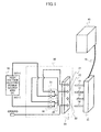
FIG. 1 is a structural diagram of a connector unit of a first embodiment of the present invention; -
FIG. 2 is a perspective view of the connector unit of the first embodiment of the present invention; -
FIG. 3 is an internal structural view of an inserting connector of the first embodiment of the present invention; -
FIG. 4 is a structural view of a receiving connector of the first embodiment of the present invention; -
FIG. 5 is a perspective view of an internal structure of an inserting connector of the first embodiment of the present invention; -
FIG. 6 is a first view for explaining a connection method of the connector unit of the first embodiment of the present invention; -
FIG. 7 is a second view for explaining the connection method of the connector unit of the first embodiment of the present invention; -
FIG. 8 is a third view for explaining the connection method of the connector unit of the first embodiment of the present invention; -
FIG. 9 is a fourth view for explaining the connection method of the connector unit of the first embodiment of the present invention; -
FIG. 10 is a perspective view of a state where a control plug terminal of the connector unit of the first embodiment of the present invention is retracted; -
FIG. 11 is a perspective view of a state where the control plug terminal of the connector unit of the first embodiment of the present invention is extended; -
FIG. 12 is a structural diagram of an electric power source supply system using the connector unit of the first embodiment of the present invention; -
FIG. 13 is a perspective view of a PDU (Power Distribution Unit) using the connector unit of the first embodiment of the present invention; -
FIG. 14 is a perspective view of an internal structure of an inserting connector of a second embodiment of the present invention; -
FIG. 15 is a view for explaining a case where a control plug terminal of an inserting connector of the second embodiment of the present invention is extended; -
FIG. 16 is a perspective view of an internal structure of the inserting connector of the second embodiment of the present invention; -
FIG. 17 is a view for explaining a case where the control plug terminal of the inserting connector of the second embodiment of the present invention is retracted; and -
FIG. 18 is a partial cross-sectional view of the internal structure of the inserting connector of the second embodiment of the present invention. - A description is given below, with reference to the
FIG. 1 through FIG. 18 of embodiments of the present invention. - An inserting connector, a receiving connector and a connector unit of a first embodiment of the present invention are discussed.
- Structures of the inserting connector, the receiving connector and the connector unit of the first embodiment of the present invention are shown in
FIG. 1 . - The connector unit of the first embodiment of the present invention includes an inserting
connector 10 and a receivingconnector 20. - The inserting
connector 10 is connected to aninformation apparatus 40 such as a server. The insertingconnector 10 includes two electricpower plug terminals control plug terminal 13, and aground plug terminal 14. The control plug terminal 13 can be retracted in an inserting direction of the insertingconnector 10. - On the other hand, the receiving
connector 20 is connected to a high voltageelectric power source 50 configured to supply the electric power. The receivingconnector 20 includes electricpower jack terminals power plug terminals control jack terminal 23 corresponding to thecontrol plug terminal 13, and aground jack terminal 24 corresponding to theground plug terminal 14. - In addition, the receiving
connector 20 includes twocontrol switches - The control switches 31 and 32 include plate-shaped switches or the like. By pushing the control switches 31 and 32, their contacts come in contact and electric current flows. In this example, an
insulation plate spring 33 is right above the control switches 31 and 32. - One end of the
control switch 31 is connected to a positive output of the high voltageelectric power source 50. Another end of thecontrol switch 31 is connected to the electricpower jack terminal 21. On the other hand, one end of thecontrol switch 32 is connected to a negative output of the high voltageelectric power source 50. Another end of thecontrol switch 32 is connected to the electricpower jack terminal 22. - In the two
control switches control switches insulation plate spring 33 by extending thecontrol plug terminal 13 of the insertingconnector 10 in the inserting direction in a state where the insertingconnector 10 and the receivingconnector 20 are engaged with each other. - Thus, by connecting the contacts of the control switches 31 and 32, electric power is supplied to the electric
power jack terminals connector 20. In addition, the electric power is supplied to theinformation apparatus 40 such as a server via the electricpower plug terminals connector 10. - Thus, in the connector unit of the embodiment of the present invention, the control switches 31 and 32 are connected to the electric
power jack terminals power jack terminals power jack terminals - In the embodiment of the present invention, the
control jack terminal 23 is not limited to having a structure engaging with thecontrol plug terminal 13 in a state where thecontrol plug terminal 13 is extended. A structure of thecontrol jack terminal 23 may be where a control switch or the like on and off controlled based on a dynamic force due to extension and retraction of thecontrol plug terminal 13 is included inside. - Next, a structure and a connecting method of a connector of the embodiment of the present invention are discussed with reference to
FIG. 2 through FIG. 5 . -
FIG. 2(a) is a perspective view of the insertingconnector 10 of the embodiment of the present invention.FIG. 2(b) is a perspective view of a main body of the receivingconnector 20 of the embodiment of the present invention. -
FIG. 3(a) is a perspective view of an internal structure of a state where thecontrol plug terminal 13 is retracted in the insertingconnector 10 of the embodiment of the present invention.FIG. 3(b) is a perspective view of an internal structure of a state where thecontrol plug terminal 13 is extended in the insertingconnector 10 of the embodiment of the present invention. -
FIG. 4(a) is a top view of the receivingconnector 20 of the embodiment of the present invention.FIG. 4(b) is a side view of the receivingconnector 20 of the embodiment of the present invention.FIG. 4(c) is a rear surface view of the receivingconnector 20 of the embodiment of the present invention. -
FIG. 5(a) is an internal structural view of the receivingconnector 20 of the embodiment of the present invention.FIG. 5(b) is an expanded view of the vicinities of the control switches 31 and 32 of the receivingconnector 20. - The inserting
connector 10 shown inFIG. 2(a) has width W1 of approximately 30 mm, length D1 of approximately 30 mm, and height H1 of approximately 16 mm. A DC electricpower source cable 15 of 400 VDC is connected to the insertingconnector 10. The electricpower plug terminals control plug terminal 13, and theground plug terminal 14 made of metal are provided at a side of the insertingconnector 10 opposite a side where thecable 15 is connected. The length A of the electricpower plug terminals ground plug terminal 14 is approximately 19 mm. - Just after being inserted in the receiving
connector 20, the insertingconnector 10 of the embodiment of the present invention is in a state shown inFIG. 3(a) . After this, by pushing a pushingbutton 16, thecontrol plug terminal 13 is extended and ahinge 17 is rotated. As a result of this, alock terminal 18 projects in a direction perpendicular to the inserting direction so that a state shown inFIG. 3(b) is formed. - On the other hand, as shown in
FIG. 2(b) andFIG. 4 , the receivingconnector 20 of the embodiment of the present invention has a structure where a part of the main body of the insertingconnector 10 is engaged with the receivingconnector 20. - The receiving
connector 20 includes the electricpower jack terminals ground jack terminal 24, and thecontrol jack terminal 23. The electricpower jack terminals power plug terminals ground jack terminal 24 is configured to be connected to theground plug terminal 14. Thecontrol jack terminal 23 is configured to be connected to thecontrol plug terminal 13 in a state where thecontrol plug terminal 13 is extended. - A terminal connected to a main body of a PDU (Power Distribution Unit) discussed below is provided at a rear surface of the main body of the receiving
connector 20. More specifically,electric power terminals ground terminal 24A are provided at the rear surface of the main body of the receivingconnector 20. Theelectric power terminal 21A is connected to the electricpower jack terminal 21 via thecontrol switch 31. Theelectric power terminal 22A is connected to the electricpower jack terminal 22 via thecontrol switch 32. Theground terminal 24A is connected to theground jack terminal 24. - The receiving
connector 20 shown inFIG. 4 has width W2 of approximately 56 mm, length D2 of approximately 40 mm, and height H2 of approximately 40.5 mm. -
FIG. 5(a) and FIG. 5(b) show internal structures of the receivingconnector 20. The twocontrol switches control jack terminal 23 of the receivingconnector 20. When theinsulation plate spring 33 provided above the twocontrol switches control switches - Since the flowing electric current is 400 VDC, it is dangerous that the head end of the
control plug terminal 13 of the receivingconnector 10 directly pushes the twocontrol switches control switches insulation plate spring 33. In this example,permanent magnets - Next, a connecting method of the inserting
connector 10 and the receivingconnector 20 of the embodiment of the present invention is discussed with reference toFIG. 6 through FIG. 8. FIG. 6 through FIG. 8 are first through third views for explaining the connection method of the insertingconnector 10 and the receivingconnector 20 of the first embodiment of the present invention. Each ofFIG. 6 through FIG. 8 shows a schematic structure of a cross section. -
FIG. 6 shows a state before the insertingconnector 10 and the receivingconnector 20 are connected to each other. In a state shown inFIG. 6 , the electricpower plug terminal 11 of the insertingconnector 10 is not connected to the electricpower jack terminal 21. - Similarly, the electric
power plug terminal 12 shown inFIG. 1 and the electricpower jack terminal 22 are not connected to each other. Theground plug terminal 14 and theground jack terminal 24 are not connected to each other. In addition, thecontrol plug terminal 13 is retracted. The pushingbutton 16 configured to extend and retract the control plug terminal 13 projects. - On the other hand, in the receiving
connector 20, thecontrol switch 31 and the electricpower jack terminal 21 are connected to each other. More specifically, thecontrol switch 31 includes aplate spring part 35 andcontacts contact 36 is connected to the electricpower jack terminal 21. Theplate spring part 35 is formed of a metal plate spring. Thecontact 37 is connected to theelectric power source 50 via theplate spring part 35. - Similarly, the electric
power plug terminal 12 shown inFIG. 1 is connected to the electricpower jack terminal 22. Thecontrol switch 32 is connected to theelectric power source 50. In addition, when a force is applied from an upper part of theinsulation plate spring 33, theinsulation plate spring 33 provided above the control switches 31 and 32 is deformed, so that the force is transmitted to the control switches 31 and 32. - Next, a state where the inserting
connector 10 is inserted in the receivingconnector 20 is shown inFIG. 7 . In this state, the electricpower jack terminal 21 and the electricpower plug terminal 11 of the receivingconnector 10 are engaged with each other. - Similarly, the electric
power plug terminal 12 and the electricpower jack terminal 22 shown inFIG. 1 are engaged with each other. Theground plug terminal 14 and theground jack terminal 24 are engaged with each other. In this state, thecontrol plug terminal 13 is kept retracted, and the pushingbutton 16 configured to extend and retract thecontrol plug terminal 13 is kept projecting. Accordingly, thecontact 37 and thecontact 36 of thecontrol switch 31 of the receivingconnector 20 are not connected. Similarly, thecontact 39 and thecontact 38 of thecontrol switch 32 not shown are not connected. - A state where the inserting
connector 10 is inserted in the receivingconnector 20 and thecontrol plug terminal 13 extends is shown inFIG. 8 . - More specifically, by pushing the pushing
button 16, thecontrol plug terminal 13 extends, and the head end of thecontrol plug terminal 13 pushes theinsulation plate spring 33 so that theplate spring 33 is bent. Due to the bending of theinsulation plate spring 33, theplate spring part 35 of thecontrol switch 31 is bent so that thecontact 37 and thecontact 36 of thecontrol switch 31 are connected. - By connecting the
contact 37 and thecontact 36 of thecontrol switch 31, electric power from theelectric power source 50 shown inFIG. 1 is supplied to the electricpower jack terminal 21. Similarly, the electric power is supplied to the electricpower jack terminal 22 shown inFIG. 1 . As a result of this, the electric power is supplied from theelectric power source 50 to theinformation apparatus 40 such as a server shown inFIG. 1 connected to the insertingconnector 10, via the electricpower plug terminals power jack terminals - Next,
contacts control switch 31 andcontacts control switch 32 are discussed with reference toFIG. 9 . - As shown in
FIG. 5 , thepermanent magnet 25A is provided in the vicinities of thecontacts control switch 31. Thepermanent magnet 25B is provided in the vicinities of thecontacts control switch 32. - Referring to
FIG. 9(a) , straight lines in thecontrol switch 31 indicate directions of the electric current flowing when thecontacts control switch 32 indicate directions of the electric current flowing when thecontacts electric power source 50 flows through the controls switches 31 and 32 and is supplied to theinformation apparatus 40 such as the server. - Here, when the
control plug terminal 13 is retracted, thecontacts control switch 31 and thecontacts control switch 32 are opened so that the flow of the electric current stops. At this moment, arcing (arcing electric current) is generated between thecontacts contacts - In this case, by providing the
permanent magnet 25A in the vicinities of thecontacts FIG. 9(b) , magnetic flux indicated by a dotted line is generated due to thepermanent magnet 25A. Thereby, a Lorentz force is generated based on Fleming's left-hand rule. As a result of this, as shown inFIG. 9(a) , the arcing is deflected as indicated by thenumerical reference 91 inFIG. 9(a) so as to be taken out. - Furthermore, by providing the
permanent magnet 25B in the vicinities of thecontacts FIG. 9(c) , magnetic flux indicated by a dotted line is generated due to thepermanent magnet 25B. Thereby, another Lorentz force is generated based on Fleming's left-hand rule. As a result of this, as shown inFIG. 9(a) , the arcing is deflected as indicated by thenumerical reference 92 inFIG. 9(a) so as to be taken out. - As a result of this, supplying of the electric power is immediately blocked, and therefore it is possible to achieve higher safety.
- In the above-discussed example, a case where two
permanent magnets FIG. 9(d) , a singlepermanent magnet 25 formed of twopermanent magnets - Next, functions of the
control plug terminal 13 and thelock terminal 18 are discussed with reference toFIG. 10 andFIG. 11 . -
FIG. 10(a) is a perspective view of a state where thecontrol plug terminal 13 is retracted in the insertingconnector 10 of the embodiment of the present invention.FIG. 10(b) is a perspective view of a state where the insertingconnector 10 and the receivingconnector 20 are engaged with each other and thecontrol plug terminal 13 is retracted. -
FIG. 11(a) is a perspective view of a state where thecontrol plug terminal 13 is extended in the insertingconnector 10 of the embodiment of the present invention.FIG. 11(b) is a perspective view of a state where the insertingconnector 10 and the receivingconnector 20 are engaged with each other and thecontrol plug terminal 13 is extended. - As shown in
FIG. 10(a) , the length C1 in the state where thecontrol plug terminal 13 is retracted is 10 mm. As shown inFIG. 11(a) , the length C2 in the state where thecontrol plug terminal 13 is extended is 14.5 mm. - As shown in
FIG. 10(b) , aconcave part 29 which corresponds to the projectedlock terminal 18 is formed in the receivingconnector 20. As shown inFIG. 11(b) , in theconcave part 29, when thelock terminal 18 projects, connection of the insertingconnector 10 and the receivingconnector 20 cannot be broken. - In the above-discussed embodiment of the present invention, by using the pushing
button 16, thecontrol plug terminal 13 is extended in the inserting direction and thelock terminal 18 projects. However, the present invention is not limited to this structure. A slide switch or the like which can move in the inserting direction, instead of the pushingbutton 16, may be used so that thecontrol plug terminal 13 can be extended in the inserting direction and thelock terminal 18 can project. - Thus, the electric power is supplied from the electric
power jack terminals control plug terminal 13 is extended. This is because it is necessary to prevent the high voltage of 400 VDC from being applied to the electricpower jack terminals connector 20 when the insertingconnector 10 is not connected to the receivingconnector 20. - In other words, if the high voltage of 400 VDC is applied to the electric
power jack terminals connector 20 when the insertingconnector 10 is not connected to the receivingconnector 20, the following problem may occur. That is, when a human touches the electricpower jack terminals power jack terminals - Thus according to the connector unit of the embodiment of the present invention, when the
control plug terminal 13 is pushed in a state where the electricpower plug terminals connector 10 are engaged with the electricpower jack terminals connector 20, an electric current flows via the control switch provided at thecontrol jack terminal 23. As a result of this, electric power is supplied to theinformation apparatus 40 via the electricpower jack terminals power plug terminals connector 10. - Next, a structure of an electric power supply system using the connector unit of the embodiment of the present invention is discussed.
-
FIG. 12 is a structural diagram of the electric power source supply system using the connector unit of the first embodiment of the present invention. - In this electric power supply system, a voltage of AC 100 V or AC 200 V supplied from the commercial
electric power source 70 is input to the high voltageelectric power source 50 so as to be converted toDC 400 V by an AC/DC convertor 51 of the high voltageelectric power source 50. Direct current electric energy can be stored in a battery or the like. Therefore, by providing abackup battery 52, it is possible to easily respond in a case of a power outage or the like. - The receiving
connector 20 of the embodiment of the present invention is connected to the high voltageelectric power source 50 via an electric power source cable, so that electric power of 400 VDC from the high voltageelectric power source 50 is supplied from the receivingconnector 20. - On the other hand, the inserting
connector 10 of the embodiment of the present invention is connected to theinformation apparatus 40 such as a server via the electricpower source cable 15. By electrically connecting the insertingconnector 10 and the receivingconnector 20, the electric power is supplied from the high voltageelectric power source 50 to theinformation apparatus 40 such as the server. - In addition, a DC/
DC convertor 41 is provided in theinformation apparatus 40 such as the server. The DC/DC convertor 41 is configured to convert 400 VDC to a DC output having a low voltage whereby an electronic component such as theCPU 42 can be operated. - In the above-discussed electric power supply system, there are several advantages. For example, since conversion from the AC of the commercial
electric power source 70 to the DC is required only one time, electric power loss is small. In addition, there is no need to pay attention to the width of the wire with a high voltage direct current 400 VDC. Because of the direct current, it is possible to store electric energy in thebattery 52 and it is possible to easily respond when the supply from the commercialelectric power source 70 stops due to a power outage. - Next, a PDU (Power Distribution Unit) using the connector unit of the embodiment of the present invention is discussed with reference to
FIG. 13 . - Here,
FIG. 13 is perspective view of the PDU using the connector unit of the first embodiment of the present invention. - The electric power of 400 VDC supplied from the high voltage electric power source shown in
FIG. 12 is input to itsdistribution board 70 for a while so that the electric power is distributed to eachPDU 30. Plural of the receivingconnectors 20 of the embodiment of the present invention are provided in eachPDU 30. It is possible to supply the electric power of 400 VDC via each receivingconnector 20. - On the other hand, plural of the information apparatuses 40 such as servers are installed in a
server rack 45. The insertingconnectors 10 configured to receive a supply of power from the electric power source are connected to thecorresponding information apparatuses 40 such as the servers via the DC electricpower source cables 15. By electrically connecting the insertingconnectors 10 to the receivingconnectors 20 provided in thePDU 30, the electric power of 400 VDC can be supplied. - In addition, in the above-discussed example, the case of 400 VDC is explained. However, the inserting connector, the receiving connector, and the connector unit can be used as long as the electric current is a direct current (DC). In the case of DC, unlike AC, there is no frequency so that it is safe for humans.
- From the perspective of influence on the human body, a voltage equal to or less than 48 V is normally used as a direct current voltage. This is because there is almost no influence due to electric shock if the voltage is equal to or less than 48 V. If the voltage is higher than 48 V, influence on human body is large and, especially, the voltage equal to or higher than 200 V is dangerous.
- In the inserting connector, the receiving connector, and the connector unit of this embodiment, safety is improved by a structure different from the conventional art. Hence, safety in the case of the voltage higher than 48 V, especially the voltage higher than 200V is improved and therefore the receiving connector and the connector unit of this embodiment are effective.
- The second embodiment of the present invention is mainly related to the inserting connector. More specifically, in the fourth embodiment of the present invention, as discussed below, extension and retraction of the control plug is done with a slide switch.
-
FIG. 14 shows a structure of the inserting connector of the fourth embodiment of the present invention. More specifically,FIG. 14(a) is a perspective view of an insertingconnector 110 in a state where acontrol plug terminal 113 is retracted.FIG. 14(b) is a perspective view of the insertingconnector 110 in a state where thecontrol plug terminal 113 is extended. - The inserting
connector 110 includes two electricpower plug terminals control plug terminal 113, aground plug terminal 114, aslide switch 116, and alock terminal 108. - The
control plug terminal 113 is extended by sliding theslide switch 116 in the inserting direction of the control plug terminal 113 from the retracted state shown inFIG. 14(a) to the extended state shown inFIG. 14(b) . - Next, with reference to
FIG. 15 andFIG. 16 , a case where thecontrol plug terminal 113 is extended in the insertingconnector 110 of this embodiment is discussed. By extending thecontrol plug terminal 113, a contact of a switch provided at the control jack terminal of the receiving connector (not shown) is changed from open to closed. -
FIG. 15(a) is an internal structural view of a state where thecontrol plug terminal 113 is retracted.FIG. 15(b) is an internal perspective view of the state where thecontrol plug terminal 113 is retracted.FIG. 15(c) is an internal structural view of an intermediate state between where thecontrol plug terminal 113 is retracted and where thecontrol plug terminal 113 is extended.FIG. 15(d) is an internal perspective view of the intermediate state between where thecontrol plug terminal 113 is retracted and where thecontrol plug terminal 113 is extended.FIG. 15(e) is an internal structural view of the state where thecontrol plug terminal 113 is extended.FIG. 15(f) is an internal perspective view of the state where thecontrol plug terminal 113 is extended.FIG. 16 is a partially expanded view ofFIG. 15(b) . - As shown in
FIG. 15(a) and FIG. 15(b) , in theslide switch 116, aU-shaped part 117 is provided inside the insertingconnector 110. Thecontrol plug terminal 113 extends via a controlplug terminal link 118. - In addition, a
coil spring 119 is provided inside the insertingconnector 110. Thecoil spring 119 is connected to one end of a transmittingpart 120. The transmittingpart 120 is configured to transmit the expansion and compression of thecoil spring 119. Another end of the transmittingpart 120 is connected to acam shaft 121 of the control plugterminal link 118 where the end part of the transmittingpart 120 can be rotated, and thecam shaft 121 can be moved in acam groove 122. - Furthermore, a
slide shaft 123 is provided in the control plugterminal link 118 so as to move in aslide groove 124. In addition, ahead end part 125 of the control plugterminal link 118 is inserted in abuffer groove 126 provided in thecontrol plug terminal 113 so as to move in thebuffer groove 126. - In the state where the
control plug terminal 113 is retracted, theslide switch 116 and the control plugterminal link 118 are positioned at a left side inFIG. 15 . Thecam shaft 121 is positioned on a leftmost side in thecam groove 122 and comes in contact with an internal part wall surface of the left side of theU-shaped part 117. Furthermore, theslide shaft 123 of the control plugterminal link 118 is positioned at a left side in theslide groove 124. Thehead end part 125 comes in contact with a left end of thebuffer groove 126. At this time, thecoil spring 119 is slightly compressed. - After this, the
slide switch 116 is moved in the inserting direction (right direction inFIG. 15 ) so as to be in the intermediate state shown inFIG. 15(c) and FIG. 15(d) . In this intermediate state, a moving direction of theslide switch 116 is perpendicular to expansion and compression directions of thecoil spring 119. - In this intermediate state, the
slide switch 116 is positioned in the substantially center part inFIG. 15 . In the control plugterminal link 118, thecam shaft 121 is pushed to the right side by the internal part wall surface at the left side of theU-shaped part 117 so as to move to the right side in thecam groove 122 and reach the center part in thecam groove 122. - At this time, although the
head end part 125 of the control plugterminal link 118 moves to a right side, the retracted state of thecontrol plug terminal 113 is maintained because thehead end part 125 moves in thebuffer groove 126. In this retracted state, thehead end part 125 comes in contact with a right end of thebuffer groove 126. In addition, in this retracted state compared to the positions shown inFIG. 15(a) and FIG. 15(b) , thecoil spring 119 is compressed more and therefore a force pushing the transmittingpart 120 up due to a restoring force of thecoil spring 119 becomes stronger. - After this, by further moving the
slide switch 116 in the inserting direction (right direction inFIG. 15 ), positions shown inFIG. 15(e) and FIG. 15(f) are reached due to the restoring force of thecoil spring 119. - In other words, due to the restoring force whereby the
coil spring 119 expands, thecam shaft 121 moves in thecam groove 122 in the right direction inFIG. 15 via the transmittingpart 120. As a result of this, via thehead end part 125 of the control plugterminal link 118, the right end of thebuffer groove 126 is pushed and thecontrol plug terminal 113 extends in the inserting direction. - In this extended state, the
slide switch 116 and the control plugterminal link 118 are moved to the right side inFIG. 15 . Furthermore, thecam shaft 121 is moved to a rightmost side in thecam groove 122 and comes in contact with an internal part wall surface of the right side of theU-shaped part 117. Furthermore, theslide shaft 123 of the control plugterminal link 118 is positioned at a right side in theslide groove 124. Thehead end part 125 comes in contact with a right end of thebuffer groove 126. At this time, thecoil spring 119 is slightly expanded compared to the intermediate state. - Thus, it is possible to extend the
control plug terminal 113 in the inserting direction. Since thecontrol plug terminal 113 is extended in the inserting direction due to the restoring force of thecoil spring 119 from the intermediate state, namely a force whereby thecoil spring 119 is expanded, this occurs for a short period of time. - Next, with reference to
FIG. 17 , a case where thecontrol plug terminal 113 is retracted in the insertingconnector 110 of this embodiment is discussed. By retracting thecontrol plug terminal 113, a contact of a switch provided at the control jack terminal of the receiving connector (not shown) is changed from closed to open. -
FIG. 17(a) is an internal structural view of a state where thecontrol plug terminal 113 is extended.FIG. 17(b) is an internal perspective view of the state where thecontrol plug terminal 113 is extended.FIG. 17(c) is an internal structural view of an intermediate state between where thecontrol plug terminal 113 is extended and where thecontrol plug terminal 113 is retracted.FIG. 17(d) is an internal perspective view of the intermediate state between where thecontrol plug terminal 113 is extended and where thecontrol plug terminal 113 is retracted.FIG. 17(e) is an internal structural view of the state where thecontrol plug terminal 113 is retracted.FIG. 17(f) is an internal perspective view of the state where thecontrol plug terminal 113 is retracted. - As shown in
FIG. 17(a) and FIG. 17(b) , in the state where thecontrol plug terminal 113 is extended, theslide switch 116 and the control plugterminal link 118 are positioned at a right side inFIG. 17 . - The
cam shaft 121 is positioned at a rightmost side in thecam groove 122 and comes in contact with an internal part wall surface of the right side of theU-shaped part 117. Furthermore, theslide shaft 123 of the control plugterminal link 118 is positioned at a right side in theslide groove 124. Ahead end part 125 comes in contact with a right end of thebuffer groove 126. At this time, thecoil spring 119 is slightly compressed. - After this, the
slide switch 116 is moved in the pulling direction (left direction inFIG. 17 ) so as to reach the intermediate state shown inFIG. 17(c) and FIG. 17(d) . In this intermediate state, a moving direction of theslide switch 116 is perpendicular to an expansion and compression direction of thecoil spring 119. - In this intermediate state, the
slide switch 116 is positioned in the substantially center part inFIG. 17 . In the control plugterminal link 118, thecam shaft 121 is pushed to the left side by the internal part wall surface at the right side of theU-shaped part 117 so as to move to the left side in thecam groove 122 and reach the center part in thecam groove 122. - At this time, although the
head end part 125 of the control plugterminal link 118 moves to a left side, the extended state of thecontrol plug terminal 113 is maintained because thehead end part 125 moves in thebuffer groove 126. In this extended state, thehead end part 125 comes in contact with a right end of thebuffer groove 126. In addition, in this extended state compared to the positions shown inFIG. 17(a) and FIG. 17(b) , thecoil spring 119 is compressed more and therefore a force pushing the transmittingpart 120 up due to a restoring force of thecoil spring 119 becomes stronger. - After this, by further moving the
slide switch 116 in the pulling direction (left direction inFIG. 17 ), positions shown inFIG. 17(e) and FIG. 17(f) are attained due to the restoring force of thecoil spring 119. - In other words, due to the restoring force whereby the
coil spring 119 expands, thecam shaft 121 moves in thecam groove 122 in the left direction inFIG. 17 via the transmittingpart 120. As a result of this, via thehead end part 125 of the control plugterminal link 118, the left end of thebuffer groove 126 is pushed and thecontrol plug terminal 113 is retracted in the inserting direction. - In this retracted state, the
slide switch 116 and the control plugterminal link 118 are moved to the left side inFIG. 17 . Furthermore, thecam shaft 121 is moved to a leftmost side in thecam groove 122 and comes in contact with an internal part wall surface of the left side of theU-shaped part 117. Furthermore, theslide shaft 123 of the control plugterminal link 118 is positioned at a left side in theslide groove 124. Thehead end part 125 comes in contact with a left end of thebuffer groove 126. At this time, thecoil spring 119 is slightly expanded compared to the intermediate state. - Thus, it is possible to retract the
control plug terminal 113 in the inserting direction. Since thecontrol plug terminal 113 is retracted in the inserting direction due to the restoring force of thecoil spring 119 from the intermediate state, namely a force whereby thecoil spring 119 is expanded, this is performed for a short period of time. - In the meantime, in a case where the
coil spring 119 is not provided, thecontrol plug terminal 113 is retracted and extended in the inserting direction by only a force of a finger of a human. Since the speed for retracting or extending differs depending on the human, the speed may be slow. - Due to the speed for retracting or extending being slow, arcing or chattering may be generated at a contact of the receiving connector (not shown) connected by the
control plug terminal 113. Such arcing or chattering may damage the contact of the receiving connector or an apparatus connected to the inserting connector. - In the receiving
connector 110 of this embodiment, thecontrol plug terminal 113 can be retracted or extended in a short period of time. Accordingly, the above-mentioned arcing or chattering can be prevented from being generated. Hence, it is possible to prevent the contact of the receiving connector or the apparatus connected to the inserting connector from being damaged. - Next, a mechanism of the inserting connector of the embodiment is discussed with reference to
FIG. 18 . -
FIG. 18(a) is a partial cross-sectional view of an inserting connector in the state where thecontrol plug terminal 113 is retracted.FIG. 18(b) is a partial cross-sectional view of the inserting connector in the state where thecontrol plug terminal 113 is in the intermediate state.FIG. 18(c) is a partial cross-sectional view of the inserting connector in the state where thecontrol plug terminal 113 is extended. - The
slide switch 116 is moved to the left side inFIG. 18(a) so that thecam shaft 121 is pushed to the left side by the internal part wall surface of the right side of theU-shaped part 117. As a result of this, thecam shaft 121 is moved to the left side in thecam groove 122 so that the control plugterminal link 118 is moved to the left side. - At this time, the
coil spring 119 is compressed by thecam shaft 121 via the transmittingpart 120. Thecoil spring 119 of the insertingconnector 110 of this embodiment is received in acoil spring holder 127. An end of thecoil spring 119 at a side not contacting the transmittingpart 120 is fixed inside thecoil spring holder 127. Furthermore, thecoil spring holder 127 is rotatably supported by the housing of the insertingconnector 110 and arotational shaft 128. - As a result of this, the intermediate state shown in
FIG. 18(b) is formed. In this state, thecoil spring 119 is compressed and the restoring force in the extending direction is large. - After this, the
slide switch 116 is further moved to the left side, and the transmittingpart 120 is pushed up by the restoring force of thecoil spring 119 so that thecam shaft 121 moves to the left side in thecam groove 122. As a result of this, thecontrol plug terminal 113 is moved in the left direction via thehead end part 125 of the control plugterminal link 118. In other words, thecontrol plug terminal 113 is extended in the inserting direction so that the extended state shown inFIG. 18(c) is formed. - Thus, it is possible to push the
control plug terminal 113 in a short period of time. - Similarly, in a case where the
control plug terminal 113 is to be retracted, it is possible to retract the control plug terminal 113 from the intermediate state due to the restoring force of thecoil spring 119. Hence, it is possible to retract thecontrol plug terminal 113 in a short period of time. - In the above-discussed examples, by using a restoring force whereby the
coil spring 119 is expanded from the compressed state, thecontrol plug terminal 113 is retracted. However, by using a structure or the like of thecam groove 122, the restoring force whereby thecoil spring 119 is compressed from the expanded state is used so that extension and retraction of thecontrol plug terminal 113 can be performed. - In addition, although the
coil spring 119 is used in the above-discussed examples, any elastic member can be used as long as the same action can be performed. - Furthermore, the inserting connector of this embodiment, instead of the inserting connector of the first embodiment, can be used. For example, the inserting connector of this embodiment can be combined with the receiving connector of the first embodiment so that the connector unit can be formed.
- According to the embodiments of the present invention, it is possible to provide an inserting connector, a receiving connector, and a connector unit whereby high voltage electric power can be safely supplied.
- All examples and conditional language recited herein are intended for pedagogical purposes to aid the reader in understanding the invention and the concepts contributed by the inventor to furthering the art, and are to be construed as being without limitation to such specifically recited examples and conditions, nor does the organization of such examples in the specification relate to a showing of the superiority or inferiority of the invention. Although the embodiments of the present invention have been described in detail, it should be understood that the various changes, substitutions, and alterations could be made hereto without departing from the spirit and scope of the invention.
- Embodiments of the present invention extend to the following statements:
-
Statement 1. A receiving connector connected to an inserting connector, the inserting connector being configured to electrically connect an electric power source and an electric apparatus receiving an electric power supply from the electric power source, the inserting connector being connected to the electric apparatus, the inserting connector including
two electric power plug terminals made of a conductor, the conductor being configured to receive the electric power supply; and
a control plug terminal configured to be extended and retracted in an inserting direction;
the receiving connector being connected to the electric power source,
the receiving connector including:- two electric power jack terminals corresponding to the electric power plug terminals; and
- a control jack terminal corresponding to the control plug terminal;
- wherein the control jack terminal includes two control switches connected to the two electric power jack terminals;
- the electric power source is configured to supply electric power from the electric power jack terminals via the two control switches; and
- contacts of the two control switches are connected by extending the control plug terminal in the control jack terminal in the inserting direction in a state where two electric power plug terminals and the two electric power jack terminals are engaged with each other, so that the electric power is supplied to the electronic apparatus.
- Statement 2. The receiving connector as defined in
statement 1,
wherein the control switch is a metal plate spring switch. - Statement 3. The receiving connector as defined in statement 2,
wherein, in the receiving connector, an insulation spring is provided between the two control switches and the control plug terminal; and
the insulation spring is bent by inserting the control plug terminal in the inserting direction so that the contacts of the control switches are connected via the insulation spring. - Statement 4. The receiving connector as defined in
statement 1,
wherein a permanent magnet is provided in the vicinity of the contact of each of the control switches; and
the permanent magnet is configured to take out arcing generated at the time when the contact of the corresponding control switch is cut to an outside, so that the electric power supply from the electric power source is cut. - Statement 5. The receiving connector as defined in
statement 1,
wherein the inserting connector further includes a ground plug terminal;
the receiving connector includes a ground jack terminal corresponding to the ground plug terminal; and
the ground plug terminal and the ground jack terminal are engaged with each other in the engaging state where the inserting connector and the receiving connector are engaged with each other. - Statement 6. The receiving connector as defined in
statement 1,
wherein the electric power supplied from the electric power source is direct current. - Statement 7. The receiving connector as defined in
statement 1,
wherein a voltage of the electric power supplied from the electric power source is higher than 48 V. - Statement 8. A connector unit configured to electrically connect an electric power source and an electric apparatus receiving an electric power supply from the electric power source, the connector unit comprising:
- an inserting connector connected to the electronic apparatus; and
- a receiving connector connected to the electric power source;
- wherein the inserting connector includes
two electric power plug terminals made of a conductor, the conductor being configured to receive the electric power supply; and
a control plug terminal configured to be extended and retracted in an inserting direction; - the receiving connector includes
two electric power jack terminals corresponding to the electric power plug terminals; and
a control jack terminal corresponding to the control plug terminal; - the control jack terminal includes two control switches connected to the two electric power jack terminals;
- the electric power source is configured to supply electric power from the electric power jack terminals via the two control switches; and
- contacts of the two control switches are connected by extending the control plug terminal in the control jack terminal in the inserting direction in a state where two electric power plug terminals and the two electric power jack terminals are engaged with each other, so that the electric power is supplied to the electronic apparatus.
- Statement 9. The connector unit as defined in statement 8,
wherein the control switch is a metal plate spring switch. -
Statement 10. The connector unit as defined in statement 8,
wherein, in the receiving connector, an insulation spring is provided between the two control switches and the control plug terminal; and
the insulation spring is bent by inserting the control plug terminal in the inserting direction so that the contacts of the control switches are connected via the insulation spring. -
Statement 11. The connector unit as defined in statement 8,
wherein a permanent magnet is provided in the vicinity of the contact of each of the control switchs; and
the permanent magnet is configured to take out arcing generated at the time when the contact of the corresponding control switch is cut to an outside, so that the electric power supply from the electric power source is cut. -
Statement 12. The connector unit as defined in statement 8,
wherein extension and retraction in the inserting direction of the control plug terminal is performed by a slide switch or a pushing button switch. -
Statement 13. The connector unit as defined in statement 8,
wherein the inserting connector further includes
a slide switch configured to perform the extension and retraction in the inserting direction of the control plug terminal via a control plug terminal link; and
an expandable and compressible coil spring;
wherein the inserting connector is in an intermediate state where a moving direction of the slide switch is perpendicular to an expansion and compression direction of the coil spring; and
the coil spring is expanded and compressed by moving the slide switch. -
Statement 14. The connector unit as defined instatement 13,
wherein the coil spring is in an expanded state or a compressed state in the case of the intermediate state; and
the control plug terminal is extended in the inserting direction via the control plug terminal link by a restoring force of the coil spring from the intermediate state. -
Statement 15. The connector unit as defined instatement 13,
wherein the coil spring is in an expanded state or a compressed state in the case of the intermediate state; and
the control plug terminal is retracted in the inserting direction via the control plug terminal link by a restoring force of the coil spring from the intermediate state. -
Statement 16. The connector unit as defined in statement 8,
wherein the inserting connector further includes a lock terminal configured to project in a direction perpendicular to the inserting direction, corresponding to the extension and retraction in the inserting direction of the control plug terminal;
the lock terminal projects in the direction perpendicular to the inserting direction by extending the plug terminal in the inserting direction;
the receiving connector includes a concave part having a configuration corresponding to the projected lock terminal; and
by extending the control plug terminal in a state where the inserting connector and the receiving connector are engaged with each other, the lock terminal is engaged into the concave part of the receiving connector in the direction perpendicular to the inserting direction, so that an engaging state of the inserting connector and the receiving connector is maintained. -
Statement 17. The connector unit as defined in statement 8,
wherein the inserting connector further includes a ground plug terminal;
the receiving connector includes a ground jack terminal corresponding to the ground plug terminal; and
the ground plug terminal and the ground jack terminal are engaged with each other in the engaging state where the inserting connector and the receiving connector are engaged with each other. -
Statement 18. The connector unit as defined in statement 8,
wherein the electric power supplied from the electric power source is direct current. - Statement 19. The connector unit as defined in statement 8,
wherein a voltage of the electric power supplied from the electric power source is higher than 48 V. -
Statement 20. An inserting connector connected to a receiving connector, the receiving connector being configured to electrically connect an electric power source and an electric apparatus receiving an electric power supply from the electric power source, the inserting connector being connected to the electric apparatus, the inserting connector comprising: two electric power plug terminals made of a conductor, the conductor being configured to receive the electric power supply; and a control plug terminal configured to be extended and retracted in an inserting direction; wherein the receiving connector is connected to the electric power source; the receiving connector includes two electric power jack terminals corresponding to the electric power plug terminals; and a control jack terminal corresponding to the control plug terminal; the control jack terminal includes two control switches connected to the two electric power jack terminals; the electric power source is configured to supply electric power from the electric power jack terminals via the two control switches; and contacts of the two control switches are connected by extending the control plug terminal in the control jack terminal in the inserting direction in a state where two electric power plug terminals and the two electric power jack terminals are engaged with each other, so that the electric power is supplied to the electronic apparatus. -
Statement 21. The inserting connector as defined instatement 20, wherein extension and retraction in the inserting direction of the control plug terminal is performed by a slide switch or a pushing button switch. -
Statement 22. The inserting connector as defined instatement 20, further comprising: a slide switch configured to perform the extension and retraction in the inserting direction of the control plug terminal via a control plug terminal link; and an expandable and compressible coil spring; wherein the inserting connector is in an intermediate state where a moving direction of the slide switch is perpendicular to an expansion and compression direction of the coil spring; and the coil spring is expanded and compressed by moving the slide switch. -
Statement 23. The inserting connector as defined instatement 22, wherein the coil spring is in an expanded state or a compressed state in the case of the intermediate state; and the control plug terminal is extended in the inserting direction via the control plug terminal link by a restoring force of the coil spring from the intermediate state. -
Statement 24. The inserting connector as defined instatement 22, wherein the coil spring is in an expanded state or a compressed state in the case of the intermediate state; and the control plug terminal is retracted in the inserting direction via the control plug terminal link by a restoring force of the coil spring from the intermediate state. -
Statement 25. The inserting connector as defined instatement 20, further comprising: a lock terminal configured to project in a direction perpendicular to the inserting direction, corresponding to the extension and retraction in the inserting direction of the control plug terminal; wherein the lock terminal projects in the direction perpendicular to the inserting direction by extending the plug terminal in the inserting direction; the receiving connector includes a concave part having a configuration corresponding to the projected lock terminal; and by extending the control plug terminal in a state where the inserting connector and the receiving connector are engaged with each other, the lock terminal is engaged into the concave part of the receiving connector in the direction perpendicular to the inserting direction, so that an engaging state of the inserting connector and the receiving connector is maintained. - Statement 26. The inserting connector as defined in
statement 20, further comprising: a ground plug terminal; wherein the receiving connector includes a ground jack terminal corresponding to the ground plug terminal; and the ground plug terminal and the ground jack terminal are engaged with each other in the engaging state where the inserting connector and the receiving connector are engaged with each other. - Statement 27. The inserting connector as defined in
statement 20, wherein the electric power supplied from the electric power source is direct current. - Statement 28. The inserting connector as defined in
statement 20, wherein a voltage of the electric power supplied from the electric power source is higher than 48 V. -
Statement 29. A receiving connector connected to an inserting connector, the inserting connector being configured to electrically connect an electric power source and an electric apparatus receiving an electric power supply from the electric power source, the inserting connector being connected to the electric apparatus, the inserting connector including two electric power plug terminals made of a conductor, the conductor being configured to receive the electric power supply; and a control plug terminal configured to be extended and retracted in an inserting direction; the receiving connector being connected to the electric power source, the receiving connector including: two electric power jack terminals corresponding to the electric power plug terminals; and a control jack terminal corresponding to the control plug terminal; wherein the control jack terminal includes two control switches connected to the two electric power jack terminals; the electric power source is configured to supply electric power from the electric power jack terminals via the two control switches; and contacts of the two control switches are connected by extending the control plug terminal in the control jack terminal in the inserting direction in a state where two electric power plug terminals and the two electric power jack terminals are engaged with each other, so that the electric power is supplied to the electronic apparatus. -
Statement 30. A connector unit configured to electrically connect an electric power source and an electric apparatus receiving an electric power supply from the electric power source, the connector unit comprising: an inserting connector connected to the electronic apparatus; and a receiving connector connected to the electric power source; wherein the inserting connector includes two electric power plug terminals made of a conductor, the conductor being configured to receive the electric power supply; and a control plug terminal configured to be extended and retracted in an inserting direction; the receiving connector includes two electric power jack terminals corresponding to the electric power plug terminals; and a control jack terminal corresponding to the control plug terminal; the control jack terminal includes two control switches connected to the two electric power jack terminals; the electric power source is configured to supply electric power from the electric power jack terminals via the two control switches; and contacts of the two control switches are connected by extending the control plug terminal in the control jack terminal in the inserting direction in a state where two electric power plug terminals and the two electric power jack terminals are engaged with each other, so that the electric power is supplied to the electronic apparatus.
Claims (12)
- An inserting connector connectable to a receiving connector that is connected to an electric power source, the inserting connector being connected to an electronic apparatus, the inserting connector comprising:two electric power plug terminals, each of which is connectable to one of electric power jack terminals of the receiving connector; anda control plug terminal configured to be extended and retracted in an inserting direction,wherein when the control plug terminal is extended in the inserting direction, the control plug terminal contacts a control jack terminal of the receiving connector that includes two control switches each connected to one of the electric power jack terminals, respectively, so as to connect contacts of each control switch so that the electric power is supplied to the electronic apparatus from the electric power jack terminals via the two control switches.
- The inserting connector as claimed in claim 1,
further comprising either one of a slide switch or a pushing button switch for extending and retracting the control plug terminal. - The inserting connector as claimed in claim 1, further comprising:a slide switch;a control plug terminal link that is movably connected to the slide switch for extending and retracting the control plug terminal; anda coil spring that is expanded and compressed by a movement of the slide switch,wherein the slide switch is positionable to an intermediate state where a moving direction of the slide switch is perpendicular to an expansion and compression direction of the coil spring.
- The inserting connector as claimed in claim 3,
wherein the control plug terminal is extended as the control plug terminal link moves by a restoring force of the coil spring when the slide switch is slid from the intermediate state. - The inserting connector as claimed in claim 3,
wherein the control plug terminal is retracted as the control plug terminal link moves by a restoring force of the coil spring when the slide switch is slid from the intermediate state. - The inserting connector as claimed in claim 1, further comprising:a lock terminal configured to project in a direction perpendicular to the inserting direction when the control plug terminal is extended,wherein the lock terminal engages with a concave provided in the receiving connector so as to maintain an engaging state of the inserting connector and the receiving connector.
- The inserting connector as claimed in claim 1, further comprising:a ground plug terminal connectable to a ground jack terminal of the receiving connector,wherein the ground plug terminal and the ground jack terminal are engaged with each other when the inserting connector and the receiving connector are engaged with each other.
- A receiving connector connectable to an inserting connector connected to an electronic apparatus and including two electric power plug terminals and a control plug terminal configured to be extended and retracted in an inserting direction, the receiving connector including:two electric power jack terminals each connectable to one of the electric power plug terminals; anda control jack terminal corresponding to the control plug terminal,wherein the control jack terminal includes two control switches each connected to one of the electric power jack terminals, respectively, andcontacts of each control switch are connected when the control plug terminal in the control jack terminal is extended in the inserting direction, so that the electric power is supplied to the electronic apparatus.
- The receiving connector as claimed in claim 8,
wherein the control switch is a metal plate spring switch. - The receiving connector as claimed in claim 8 or 9, further comprising:an insulation spring provided between the two control switches and the control plug terminal,wherein the insulation spring is bent when the control plug terminal is inserted so that the contacts of the control switches are connected via the insulation spring.
- The receiving connector as claimed in claim 8, further comprising:a permanent magnet provided in the vicinity of the contacts of each of the control switches,wherein the permanent magnet is configured to extinguish arc generated when the contacts of the corresponding control switch are separated.
- The receiving connector as claimed in claim 8, further comprising:a ground jack terminal connectable to a ground plug terminal of the inserting connector,wherein the ground plug terminal and the ground jack terminal are engaged with each other when the inserting connector and the receiving connector are engaged with each other.
Applications Claiming Priority (3)
| Application Number | Priority Date | Filing Date | Title |
|---|---|---|---|
| JP2008196922 | 2008-07-30 | ||
| JP2008251497A JP5119112B2 (en) | 2008-07-30 | 2008-09-29 | Male connector, female connector and connector |
| EP20090158180 EP2149940B1 (en) | 2008-07-30 | 2009-04-17 | Inserting connector, receiving connector, and connector unit |
Related Parent Applications (1)
| Application Number | Title | Priority Date | Filing Date |
|---|---|---|---|
| EP20090158180 Division EP2149940B1 (en) | 2008-07-30 | 2009-04-17 | Inserting connector, receiving connector, and connector unit |
Publications (2)
| Publication Number | Publication Date |
|---|---|
| EP2899815A1 true EP2899815A1 (en) | 2015-07-29 |
| EP2899815B1 EP2899815B1 (en) | 2020-03-04 |
Family
ID=40886519
Family Applications (2)
| Application Number | Title | Priority Date | Filing Date |
|---|---|---|---|
| EP20090158180 Not-in-force EP2149940B1 (en) | 2008-07-30 | 2009-04-17 | Inserting connector, receiving connector, and connector unit |
| EP15151836.2A Active EP2899815B1 (en) | 2008-07-30 | 2009-04-17 | Inserting connector, receiving connector, and connector unit |
Family Applications Before (1)
| Application Number | Title | Priority Date | Filing Date |
|---|---|---|---|
| EP20090158180 Not-in-force EP2149940B1 (en) | 2008-07-30 | 2009-04-17 | Inserting connector, receiving connector, and connector unit |
Country Status (6)
| Country | Link |
|---|---|
| US (1) | US7982144B2 (en) |
| EP (2) | EP2149940B1 (en) |
| JP (1) | JP5119112B2 (en) |
| KR (1) | KR101053963B1 (en) |
| CN (1) | CN101640350B (en) |
| TW (1) | TWI384704B (en) |
Cited By (1)
| Publication number | Priority date | Publication date | Assignee | Title |
|---|---|---|---|---|
| CN112165823A (en) * | 2020-09-22 | 2021-01-01 | 科华恒盛股份有限公司 | Safety protection device applied to connector and safety control method |
Families Citing this family (27)
| Publication number | Priority date | Publication date | Assignee | Title |
|---|---|---|---|---|
| DE102009042569B3 (en) * | 2009-09-23 | 2011-05-05 | SCHLÖGL, Hilde | plug-in coupling |
| US7938660B1 (en) * | 2009-11-13 | 2011-05-10 | Fujitsu Component Limited | Connector unit with a male connector having a control terminal with a switch |
| JP5330197B2 (en) * | 2009-11-13 | 2013-10-30 | 富士通コンポーネント株式会社 | Connector device and female connector |
| JP5395629B2 (en) * | 2009-11-13 | 2014-01-22 | 富士通コンポーネント株式会社 | Connector device and male connector |
| JP5479036B2 (en) * | 2009-11-13 | 2014-04-23 | 富士通コンポーネント株式会社 | Connector device, female connector, and male connector |
| JP5079053B2 (en) * | 2010-05-26 | 2012-11-21 | 三菱電機株式会社 | Power supply connector and power supply plug |
| WO2012164980A1 (en) | 2011-06-02 | 2012-12-06 | 株式会社村田製作所 | Connector having switch |
| DE102011109920B4 (en) * | 2011-08-10 | 2021-10-07 | Ellenberger & Poensgen Gmbh | Mechatronic multiple connector system |
| JP5658825B2 (en) * | 2011-08-11 | 2015-01-28 | 富士通コンポーネント株式会社 | Connector and connector bar |
| EP2642611A1 (en) * | 2012-03-19 | 2013-09-25 | Nigel Greig | Connector apparatus |
| US9420663B1 (en) * | 2015-04-16 | 2016-08-16 | Aleddra Inc. | Linear solid-state lighting with an arc prevention switch mechanism free of fire and shock hazards |
| CN104079155B (en) * | 2013-03-28 | 2017-10-17 | 艾默生网络能源系统北美公司 | A kind of soft starting circuit and control method |
| JP6161974B2 (en) * | 2013-06-26 | 2017-07-12 | 富士通コンポーネント株式会社 | connector |
| JP6306882B2 (en) * | 2013-12-27 | 2018-04-04 | 富士通コンポーネント株式会社 | connector |
| KR200473811Y1 (en) * | 2014-01-27 | 2014-08-05 | 이승민 | Safety connector for illuminator |
| JP6418079B2 (en) | 2015-06-24 | 2018-11-07 | Smk株式会社 | Contact structure |
| US9728880B2 (en) * | 2015-09-30 | 2017-08-08 | Smk Corporation | Hotline contacting structure |
| JP6296037B2 (en) * | 2015-10-22 | 2018-03-20 | Smk株式会社 | Contact structure |
| DE202015106121U1 (en) * | 2015-11-12 | 2017-02-16 | Tridonic Gmbh & Co Kg | Pluggable electrical connection device |
| JP6618816B2 (en) * | 2016-01-22 | 2019-12-11 | 富士通コンポーネント株式会社 | Connector and connector device |
| DE102016204505A1 (en) * | 2016-03-18 | 2017-09-21 | BSH Hausgeräte GmbH | Device for locking a plug to a switch socket |
| JP2018028995A (en) * | 2016-08-16 | 2018-02-22 | 有限会社R&K Japan | Ac-dc connector and arc breaker mechanism |
| JP2018055994A (en) * | 2016-09-29 | 2018-04-05 | Smk株式会社 | Arc discharge prevention structure of socket |
| JP6974926B2 (en) | 2017-07-10 | 2021-12-01 | 胡 斐凡HU, Feifan | Insertion detector for safety socket and its plug pin |
| CN108110198A (en) * | 2017-12-18 | 2018-06-01 | 浙江动新能源动力科技股份有限公司 | A kind of belt switch Mechanism Combination formula battery pack inserting piece device |
| DE102019111691B4 (en) * | 2019-01-11 | 2020-10-15 | Hanon Systems | Arrangement for plug-in electrical connections and device for driving a compressor with the arrangement |
| US11923642B2 (en) * | 2021-02-10 | 2024-03-05 | Juniper Networks, Inc. | Apparatus, system, and method for protecting power connectors against high-power arcing |
Citations (7)
| Publication number | Priority date | Publication date | Assignee | Title |
|---|---|---|---|---|
| US4472611A (en) * | 1981-12-21 | 1984-09-18 | Societe D'exploitation Des Procedes Marechal (Sepm) | Current supply connector comprising a plug socket with pivotal contact-strips and a plug with a push-rod unit |
| US4678254A (en) * | 1984-12-27 | 1987-07-07 | Societe D'exploitation Des Procedes Marechal (Sepm) | High intensity power plug |
| JPH0582208A (en) | 1991-09-20 | 1993-04-02 | Fujitsu Ltd | Connector |
| US5394128A (en) * | 1991-03-28 | 1995-02-28 | Kilovac Corporation | DC vacuum relay device |
| US5546061A (en) * | 1994-02-22 | 1996-08-13 | Nippondenso Co., Ltd. | Plunger type electromagnetic relay with arc extinguishing structure |
| JP2003031301A (en) | 2001-07-17 | 2003-01-31 | Fujitsu Denso Ltd | Electric connector |
| WO2007072581A1 (en) * | 2005-12-22 | 2007-06-28 | Matsushita Electric Works, Ltd. | Improved electrical outlets and plugs with local power enabling and disabling |
Family Cites Families (16)
| Publication number | Priority date | Publication date | Assignee | Title |
|---|---|---|---|---|
| GB437309A (en) | 1934-05-09 | 1935-10-28 | Walsall Conduits Ltd | Improvements in or relating to combined electric switches and plug couplings |
| DE2725397A1 (en) * | 1977-06-04 | 1978-12-07 | Graesslin Feinwerktech | DEVICE FOR TIMER SWITCHES |
| US4356368A (en) * | 1980-05-01 | 1982-10-26 | Mcgill Manufacturing Company, Inc. | Auxiliary switch assembly for a power contactor |
| JPH0353475A (en) * | 1989-07-21 | 1991-03-07 | Hitachi Ltd | Outlet with power conversion function and plug with information transmitting function |
| JPH062946U (en) * | 1992-06-10 | 1994-01-14 | 三菱自動車工業株式会社 | Charging connector for separate charger |
| JPH069076U (en) * | 1992-07-09 | 1994-02-04 | カシオ計算機株式会社 | Connector device |
| US5773368A (en) * | 1996-01-22 | 1998-06-30 | Motorola, Inc. | Method of etching adjacent layers |
| US5641292A (en) * | 1995-09-15 | 1997-06-24 | Fann; Jenn-Wang | Dual-use electric plug |
| KR100573088B1 (en) * | 1998-07-20 | 2006-09-22 | (주)한국이에프티엔지니어링 | Grounding plug device |
| US6590169B2 (en) * | 2001-10-22 | 2003-07-08 | Richard J. Martinez | Switch assembly for a power accessory |
| TWM245644U (en) * | 2002-10-21 | 2004-10-01 | Simula Co Ltd | Power plug and power socket with detection pins |
| US7196293B2 (en) | 2004-04-30 | 2007-03-27 | The First Years Inc. | Timed accessory adapter |
| FR2890618B1 (en) * | 2005-09-09 | 2008-02-22 | Sc2N Sa | CONTROL ASSEMBLY, IN PARTICULAR FOR A MOTOR VEHICLE HIGH COLUMN |
| US7723630B1 (en) * | 2005-09-23 | 2010-05-25 | Southwire Company | Remote safety switch |
| KR20060006750A (en) * | 2005-12-26 | 2006-01-19 | 박성원 | A outlet equipped with a switch for attaching to a wall socket |
| US7754985B2 (en) * | 2007-04-03 | 2010-07-13 | Deere & Company | Electronic switch assembly with configurable functionality |
-
2008
- 2008-09-29 JP JP2008251497A patent/JP5119112B2/en active Active
-
2009
- 2009-04-08 US US12/420,106 patent/US7982144B2/en active Active
- 2009-04-14 TW TW98112344A patent/TWI384704B/en active
- 2009-04-17 EP EP20090158180 patent/EP2149940B1/en not_active Not-in-force
- 2009-04-17 EP EP15151836.2A patent/EP2899815B1/en active Active
- 2009-05-06 KR KR1020090039291A patent/KR101053963B1/en active IP Right Grant
- 2009-05-08 CN CN2009101405752A patent/CN101640350B/en active Active
Patent Citations (7)
| Publication number | Priority date | Publication date | Assignee | Title |
|---|---|---|---|---|
| US4472611A (en) * | 1981-12-21 | 1984-09-18 | Societe D'exploitation Des Procedes Marechal (Sepm) | Current supply connector comprising a plug socket with pivotal contact-strips and a plug with a push-rod unit |
| US4678254A (en) * | 1984-12-27 | 1987-07-07 | Societe D'exploitation Des Procedes Marechal (Sepm) | High intensity power plug |
| US5394128A (en) * | 1991-03-28 | 1995-02-28 | Kilovac Corporation | DC vacuum relay device |
| JPH0582208A (en) | 1991-09-20 | 1993-04-02 | Fujitsu Ltd | Connector |
| US5546061A (en) * | 1994-02-22 | 1996-08-13 | Nippondenso Co., Ltd. | Plunger type electromagnetic relay with arc extinguishing structure |
| JP2003031301A (en) | 2001-07-17 | 2003-01-31 | Fujitsu Denso Ltd | Electric connector |
| WO2007072581A1 (en) * | 2005-12-22 | 2007-06-28 | Matsushita Electric Works, Ltd. | Improved electrical outlets and plugs with local power enabling and disabling |
Cited By (2)
| Publication number | Priority date | Publication date | Assignee | Title |
|---|---|---|---|---|
| CN112165823A (en) * | 2020-09-22 | 2021-01-01 | 科华恒盛股份有限公司 | Safety protection device applied to connector and safety control method |
| CN112165823B (en) * | 2020-09-22 | 2022-07-05 | 科华数据股份有限公司 | Safety protection device applied to connector and safety control method |
Also Published As
| Publication number | Publication date |
|---|---|
| EP2149940B1 (en) | 2015-02-18 |
| KR20100013248A (en) | 2010-02-09 |
| TWI384704B (en) | 2013-02-01 |
| CN101640350A (en) | 2010-02-03 |
| US7982144B2 (en) | 2011-07-19 |
| EP2899815B1 (en) | 2020-03-04 |
| JP5119112B2 (en) | 2013-01-16 |
| JP2010056055A (en) | 2010-03-11 |
| US20100029110A1 (en) | 2010-02-04 |
| EP2149940A1 (en) | 2010-02-03 |
| CN101640350B (en) | 2012-09-19 |
| KR101053963B1 (en) | 2011-08-04 |
| TW201006072A (en) | 2010-02-01 |
Similar Documents
| Publication | Publication Date | Title |
|---|---|---|
| US7982144B2 (en) | Inserting connector, receiving connector, and connector unit | |
| US7982145B2 (en) | Inserting connector, receiving connector, and connector unit | |
| US7942684B1 (en) | Connector device, receiving connector, and inserting connector | |
| US7938660B1 (en) | Connector unit with a male connector having a control terminal with a switch | |
| EP2906029B1 (en) | Electronic device | |
| US8133066B2 (en) | Connector apparatus and receiving connector of the connector apparatus | |
| EP2538503B1 (en) | Connector apparatus and connector | |
| EP2056326A1 (en) | Modular electric circuit breaker | |
| JP5395629B2 (en) | Connector device and male connector | |
| JP5732152B2 (en) | Power supply unit | |
| JP5330196B2 (en) | Connector device and male connector | |
| JP2016096043A (en) | Connector integrating plug-in fuse holder and interlock mechanism |
Legal Events
| Date | Code | Title | Description |
|---|---|---|---|
| PUAI | Public reference made under article 153(3) epc to a published international application that has entered the european phase |
Free format text: ORIGINAL CODE: 0009012 |
|
| 17P | Request for examination filed |
Effective date: 20150120 |
|
| AC | Divisional application: reference to earlier application |
Ref document number: 2149940 Country of ref document: EP Kind code of ref document: P |
|
| AK | Designated contracting states |
Kind code of ref document: A1 Designated state(s): AT BE BG CH CY CZ DE DK EE ES FI FR GB GR HR HU IE IS IT LI LT LU LV MC MK MT NL NO PL PT RO SE SI SK TR |
|
| 17P | Request for examination filed |
Effective date: 20151119 |
|
| RBV | Designated contracting states (corrected) |
Designated state(s): AT BE BG CH CY CZ DE DK EE ES FI FR GB GR HR HU IE IS IT LI LT LU LV MC MK MT NL NO PL PT RO SE SI SK TR |
|
| 17Q | First examination report despatched |
Effective date: 20160527 |
|
| STAA | Information on the status of an ep patent application or granted ep patent |
Free format text: STATUS: EXAMINATION IS IN PROGRESS |
|
| RAP1 | Party data changed (applicant data changed or rights of an application transferred) |
Owner name: FUJITSU COMPONENT LIMITED |
|
| GRAP | Despatch of communication of intention to grant a patent |
Free format text: ORIGINAL CODE: EPIDOSNIGR1 |
|
| STAA | Information on the status of an ep patent application or granted ep patent |
Free format text: STATUS: GRANT OF PATENT IS INTENDED |
|
| INTG | Intention to grant announced |
Effective date: 20190927 |
|
| GRAS | Grant fee paid |
Free format text: ORIGINAL CODE: EPIDOSNIGR3 |
|
| GRAA | (expected) grant |
Free format text: ORIGINAL CODE: 0009210 |
|
| STAA | Information on the status of an ep patent application or granted ep patent |
Free format text: STATUS: THE PATENT HAS BEEN GRANTED |
|
| AC | Divisional application: reference to earlier application |
Ref document number: 2149940 Country of ref document: EP Kind code of ref document: P |
|
| AK | Designated contracting states |
Kind code of ref document: B1 Designated state(s): AT BE BG CH CY CZ DE DK EE ES FI FR GB GR HR HU IE IS IT LI LT LU LV MC MK MT NL NO PL PT RO SE SI SK TR |
|
| REG | Reference to a national code |
Ref country code: GB Ref legal event code: FG4D |
|
| REG | Reference to a national code |
Ref country code: CH Ref legal event code: EP |
|
| REG | Reference to a national code |
Ref country code: AT Ref legal event code: REF Ref document number: 1241462 Country of ref document: AT Kind code of ref document: T Effective date: 20200315 |
|
| REG | Reference to a national code |
Ref country code: DE Ref legal event code: R096 Ref document number: 602009061376 Country of ref document: DE |
|
| REG | Reference to a national code |
Ref country code: IE Ref legal event code: FG4D |
|
| PG25 | Lapsed in a contracting state [announced via postgrant information from national office to epo] |
Ref country code: NO Free format text: LAPSE BECAUSE OF FAILURE TO SUBMIT A TRANSLATION OF THE DESCRIPTION OR TO PAY THE FEE WITHIN THE PRESCRIBED TIME-LIMIT Effective date: 20200604 Ref country code: FI Free format text: LAPSE BECAUSE OF FAILURE TO SUBMIT A TRANSLATION OF THE DESCRIPTION OR TO PAY THE FEE WITHIN THE PRESCRIBED TIME-LIMIT Effective date: 20200304 |
|
| REG | Reference to a national code |
Ref country code: NL Ref legal event code: MP Effective date: 20200304 |
|
| PG25 | Lapsed in a contracting state [announced via postgrant information from national office to epo] |
Ref country code: GR Free format text: LAPSE BECAUSE OF FAILURE TO SUBMIT A TRANSLATION OF THE DESCRIPTION OR TO PAY THE FEE WITHIN THE PRESCRIBED TIME-LIMIT Effective date: 20200605 Ref country code: HR Free format text: LAPSE BECAUSE OF FAILURE TO SUBMIT A TRANSLATION OF THE DESCRIPTION OR TO PAY THE FEE WITHIN THE PRESCRIBED TIME-LIMIT Effective date: 20200304 Ref country code: LV Free format text: LAPSE BECAUSE OF FAILURE TO SUBMIT A TRANSLATION OF THE DESCRIPTION OR TO PAY THE FEE WITHIN THE PRESCRIBED TIME-LIMIT Effective date: 20200304 Ref country code: SE Free format text: LAPSE BECAUSE OF FAILURE TO SUBMIT A TRANSLATION OF THE DESCRIPTION OR TO PAY THE FEE WITHIN THE PRESCRIBED TIME-LIMIT Effective date: 20200304 Ref country code: BG Free format text: LAPSE BECAUSE OF FAILURE TO SUBMIT A TRANSLATION OF THE DESCRIPTION OR TO PAY THE FEE WITHIN THE PRESCRIBED TIME-LIMIT Effective date: 20200604 |
|
| REG | Reference to a national code |
Ref country code: LT Ref legal event code: MG4D |
|
| PG25 | Lapsed in a contracting state [announced via postgrant information from national office to epo] |
Ref country code: NL Free format text: LAPSE BECAUSE OF FAILURE TO SUBMIT A TRANSLATION OF THE DESCRIPTION OR TO PAY THE FEE WITHIN THE PRESCRIBED TIME-LIMIT Effective date: 20200304 |
|
| PG25 | Lapsed in a contracting state [announced via postgrant information from national office to epo] |
Ref country code: ES Free format text: LAPSE BECAUSE OF FAILURE TO SUBMIT A TRANSLATION OF THE DESCRIPTION OR TO PAY THE FEE WITHIN THE PRESCRIBED TIME-LIMIT Effective date: 20200304 Ref country code: LT Free format text: LAPSE BECAUSE OF FAILURE TO SUBMIT A TRANSLATION OF THE DESCRIPTION OR TO PAY THE FEE WITHIN THE PRESCRIBED TIME-LIMIT Effective date: 20200304 Ref country code: PT Free format text: LAPSE BECAUSE OF FAILURE TO SUBMIT A TRANSLATION OF THE DESCRIPTION OR TO PAY THE FEE WITHIN THE PRESCRIBED TIME-LIMIT Effective date: 20200729 Ref country code: EE Free format text: LAPSE BECAUSE OF FAILURE TO SUBMIT A TRANSLATION OF THE DESCRIPTION OR TO PAY THE FEE WITHIN THE PRESCRIBED TIME-LIMIT Effective date: 20200304 Ref country code: IS Free format text: LAPSE BECAUSE OF FAILURE TO SUBMIT A TRANSLATION OF THE DESCRIPTION OR TO PAY THE FEE WITHIN THE PRESCRIBED TIME-LIMIT Effective date: 20200704 Ref country code: RO Free format text: LAPSE BECAUSE OF FAILURE TO SUBMIT A TRANSLATION OF THE DESCRIPTION OR TO PAY THE FEE WITHIN THE PRESCRIBED TIME-LIMIT Effective date: 20200304 Ref country code: CZ Free format text: LAPSE BECAUSE OF FAILURE TO SUBMIT A TRANSLATION OF THE DESCRIPTION OR TO PAY THE FEE WITHIN THE PRESCRIBED TIME-LIMIT Effective date: 20200304 Ref country code: SK Free format text: LAPSE BECAUSE OF FAILURE TO SUBMIT A TRANSLATION OF THE DESCRIPTION OR TO PAY THE FEE WITHIN THE PRESCRIBED TIME-LIMIT Effective date: 20200304 |
|
| REG | Reference to a national code |
Ref country code: AT Ref legal event code: MK05 Ref document number: 1241462 Country of ref document: AT Kind code of ref document: T Effective date: 20200304 |
|
| REG | Reference to a national code |
Ref country code: CH Ref legal event code: PL |
|
| REG | Reference to a national code |
Ref country code: DE Ref legal event code: R097 Ref document number: 602009061376 Country of ref document: DE |
|
| PG25 | Lapsed in a contracting state [announced via postgrant information from national office to epo] |
Ref country code: MC Free format text: LAPSE BECAUSE OF FAILURE TO SUBMIT A TRANSLATION OF THE DESCRIPTION OR TO PAY THE FEE WITHIN THE PRESCRIBED TIME-LIMIT Effective date: 20200304 |
|
| PLBE | No opposition filed within time limit |
Free format text: ORIGINAL CODE: 0009261 |
|
| STAA | Information on the status of an ep patent application or granted ep patent |
Free format text: STATUS: NO OPPOSITION FILED WITHIN TIME LIMIT |
|
| PG25 | Lapsed in a contracting state [announced via postgrant information from national office to epo] |
Ref country code: LU Free format text: LAPSE BECAUSE OF NON-PAYMENT OF DUE FEES Effective date: 20200417 Ref country code: CH Free format text: LAPSE BECAUSE OF NON-PAYMENT OF DUE FEES Effective date: 20200430 Ref country code: IT Free format text: LAPSE BECAUSE OF FAILURE TO SUBMIT A TRANSLATION OF THE DESCRIPTION OR TO PAY THE FEE WITHIN THE PRESCRIBED TIME-LIMIT Effective date: 20200304 Ref country code: AT Free format text: LAPSE BECAUSE OF FAILURE TO SUBMIT A TRANSLATION OF THE DESCRIPTION OR TO PAY THE FEE WITHIN THE PRESCRIBED TIME-LIMIT Effective date: 20200304 Ref country code: DK Free format text: LAPSE BECAUSE OF FAILURE TO SUBMIT A TRANSLATION OF THE DESCRIPTION OR TO PAY THE FEE WITHIN THE PRESCRIBED TIME-LIMIT Effective date: 20200304 Ref country code: LI Free format text: LAPSE BECAUSE OF NON-PAYMENT OF DUE FEES Effective date: 20200430 |
|
| REG | Reference to a national code |
Ref country code: BE Ref legal event code: MM Effective date: 20200430 |
|
| 26N | No opposition filed |
Effective date: 20201207 |
|
| PG25 | Lapsed in a contracting state [announced via postgrant information from national office to epo] |
Ref country code: BE Free format text: LAPSE BECAUSE OF NON-PAYMENT OF DUE FEES Effective date: 20200430 Ref country code: PL Free format text: LAPSE BECAUSE OF FAILURE TO SUBMIT A TRANSLATION OF THE DESCRIPTION OR TO PAY THE FEE WITHIN THE PRESCRIBED TIME-LIMIT Effective date: 20200304 Ref country code: SI Free format text: LAPSE BECAUSE OF FAILURE TO SUBMIT A TRANSLATION OF THE DESCRIPTION OR TO PAY THE FEE WITHIN THE PRESCRIBED TIME-LIMIT Effective date: 20200304 |
|
| PG25 | Lapsed in a contracting state [announced via postgrant information from national office to epo] |
Ref country code: IE Free format text: LAPSE BECAUSE OF NON-PAYMENT OF DUE FEES Effective date: 20200417 |
|
| REG | Reference to a national code |
Ref country code: DE Ref legal event code: R082 Ref document number: 602009061376 Country of ref document: DE Representative=s name: HOFFMANN - EITLE PATENT- UND RECHTSANWAELTE PA, DE Ref country code: DE Ref legal event code: R081 Ref document number: 602009061376 Country of ref document: DE Owner name: TERADA CO., LTD., JP Free format text: FORMER OWNER: FUJITSU COMPONENT LIMITED, TOKYO, JP |
|
| REG | Reference to a national code |
Ref country code: GB Ref legal event code: 732E Free format text: REGISTERED BETWEEN 20210708 AND 20210714 |
|
| PG25 | Lapsed in a contracting state [announced via postgrant information from national office to epo] |
Ref country code: TR Free format text: LAPSE BECAUSE OF FAILURE TO SUBMIT A TRANSLATION OF THE DESCRIPTION OR TO PAY THE FEE WITHIN THE PRESCRIBED TIME-LIMIT Effective date: 20200304 Ref country code: MT Free format text: LAPSE BECAUSE OF FAILURE TO SUBMIT A TRANSLATION OF THE DESCRIPTION OR TO PAY THE FEE WITHIN THE PRESCRIBED TIME-LIMIT Effective date: 20200304 Ref country code: CY Free format text: LAPSE BECAUSE OF FAILURE TO SUBMIT A TRANSLATION OF THE DESCRIPTION OR TO PAY THE FEE WITHIN THE PRESCRIBED TIME-LIMIT Effective date: 20200304 |
|
| PG25 | Lapsed in a contracting state [announced via postgrant information from national office to epo] |
Ref country code: MK Free format text: LAPSE BECAUSE OF FAILURE TO SUBMIT A TRANSLATION OF THE DESCRIPTION OR TO PAY THE FEE WITHIN THE PRESCRIBED TIME-LIMIT Effective date: 20200304 |
|
| PGFP | Annual fee paid to national office [announced via postgrant information from national office to epo] |
Ref country code: FR Payment date: 20230124 Year of fee payment: 15 |
|
| PGFP | Annual fee paid to national office [announced via postgrant information from national office to epo] |
Ref country code: DE Payment date: 20230315 Year of fee payment: 15 |
|
| PGFP | Annual fee paid to national office [announced via postgrant information from national office to epo] |
Ref country code: GB Payment date: 20230421 Year of fee payment: 15 |