EP2913013A1 - Methods and devices for cutting tissue - Google Patents
Methods and devices for cutting tissue Download PDFInfo
- Publication number
- EP2913013A1 EP2913013A1 EP14194521.2A EP14194521A EP2913013A1 EP 2913013 A1 EP2913013 A1 EP 2913013A1 EP 14194521 A EP14194521 A EP 14194521A EP 2913013 A1 EP2913013 A1 EP 2913013A1
- Authority
- EP
- European Patent Office
- Prior art keywords
- cutting element
- cutting
- raised
- catheter
- edge
- Prior art date
- Legal status (The legal status is an assumption and is not a legal conclusion. Google has not performed a legal analysis and makes no representation as to the accuracy of the status listed.)
- Granted
Links
- 238000005520 cutting process Methods 0.000 title claims abstract description 428
- 238000000034 method Methods 0.000 title description 23
- 239000000463 material Substances 0.000 abstract description 68
- 239000002245 particle Substances 0.000 abstract description 27
- 230000010355 oscillation Effects 0.000 abstract description 2
- 210000001519 tissue Anatomy 0.000 description 63
- 210000004204 blood vessel Anatomy 0.000 description 8
- 210000004872 soft tissue Anatomy 0.000 description 4
- 230000001154 acute effect Effects 0.000 description 3
- 230000017531 blood circulation Effects 0.000 description 3
- 230000004048 modification Effects 0.000 description 3
- 238000012986 modification Methods 0.000 description 3
- UONOETXJSWQNOL-UHFFFAOYSA-N tungsten carbide Chemical compound [W+]#[C-] UONOETXJSWQNOL-UHFFFAOYSA-N 0.000 description 3
- 206010003210 Arteriosclerosis Diseases 0.000 description 2
- 208000037260 Atherosclerotic Plaque Diseases 0.000 description 2
- 230000008901 benefit Effects 0.000 description 2
- 230000003993 interaction Effects 0.000 description 2
- 230000036316 preload Effects 0.000 description 2
- OYPRJOBELJOOCE-UHFFFAOYSA-N Calcium Chemical compound [Ca] OYPRJOBELJOOCE-UHFFFAOYSA-N 0.000 description 1
- ZOKXTWBITQBERF-UHFFFAOYSA-N Molybdenum Chemical compound [Mo] ZOKXTWBITQBERF-UHFFFAOYSA-N 0.000 description 1
- 229910052581 Si3N4 Inorganic materials 0.000 description 1
- 229910000831 Steel Inorganic materials 0.000 description 1
- 229910052791 calcium Inorganic materials 0.000 description 1
- 239000011575 calcium Substances 0.000 description 1
- 238000005266 casting Methods 0.000 description 1
- 239000000919 ceramic Substances 0.000 description 1
- 239000010941 cobalt Substances 0.000 description 1
- 229910017052 cobalt Inorganic materials 0.000 description 1
- GUTLYIVDDKVIGB-UHFFFAOYSA-N cobalt atom Chemical compound [Co] GUTLYIVDDKVIGB-UHFFFAOYSA-N 0.000 description 1
- 230000006835 compression Effects 0.000 description 1
- 238000007906 compression Methods 0.000 description 1
- 239000012141 concentrate Substances 0.000 description 1
- 239000013070 direct material Substances 0.000 description 1
- 239000012530 fluid Substances 0.000 description 1
- 238000003698 laser cutting Methods 0.000 description 1
- 238000003754 machining Methods 0.000 description 1
- 229910052751 metal Inorganic materials 0.000 description 1
- 239000002184 metal Substances 0.000 description 1
- 150000002739 metals Chemical class 0.000 description 1
- 239000000203 mixture Substances 0.000 description 1
- 229910052750 molybdenum Inorganic materials 0.000 description 1
- 239000011733 molybdenum Substances 0.000 description 1
- 238000004881 precipitation hardening Methods 0.000 description 1
- HBMJWWWQQXIZIP-UHFFFAOYSA-N silicon carbide Chemical compound [Si+]#[C-] HBMJWWWQQXIZIP-UHFFFAOYSA-N 0.000 description 1
- 229910010271 silicon carbide Inorganic materials 0.000 description 1
- HQVNEWCFYHHQES-UHFFFAOYSA-N silicon nitride Chemical compound N12[Si]34N5[Si]62N3[Si]51N64 HQVNEWCFYHHQES-UHFFFAOYSA-N 0.000 description 1
- 238000005245 sintering Methods 0.000 description 1
- 238000004513 sizing Methods 0.000 description 1
- 238000009987 spinning Methods 0.000 description 1
- 239000010959 steel Substances 0.000 description 1
Images


Classifications
-
- A—HUMAN NECESSITIES
- A61—MEDICAL OR VETERINARY SCIENCE; HYGIENE
- A61B—DIAGNOSIS; SURGERY; IDENTIFICATION
- A61B17/00—Surgical instruments, devices or methods, e.g. tourniquets
- A61B17/32—Surgical cutting instruments
- A61B17/3205—Excision instruments
- A61B17/3207—Atherectomy devices working by cutting or abrading; Similar devices specially adapted for non-vascular obstructions
- A61B17/320783—Atherectomy devices working by cutting or abrading; Similar devices specially adapted for non-vascular obstructions through side-hole, e.g. sliding or rotating cutter inside catheter
-
- A—HUMAN NECESSITIES
- A61—MEDICAL OR VETERINARY SCIENCE; HYGIENE
- A61B—DIAGNOSIS; SURGERY; IDENTIFICATION
- A61B17/00—Surgical instruments, devices or methods, e.g. tourniquets
- A61B17/22—Implements for squeezing-off ulcers or the like on the inside of inner organs of the body; Implements for scraping-out cavities of body organs, e.g. bones; Calculus removers; Calculus smashing apparatus; Apparatus for removing obstructions in blood vessels, not otherwise provided for
-
- A—HUMAN NECESSITIES
- A61—MEDICAL OR VETERINARY SCIENCE; HYGIENE
- A61B—DIAGNOSIS; SURGERY; IDENTIFICATION
- A61B17/00—Surgical instruments, devices or methods, e.g. tourniquets
- A61B17/32—Surgical cutting instruments
- A61B17/3205—Excision instruments
- A61B17/3207—Atherectomy devices working by cutting or abrading; Similar devices specially adapted for non-vascular obstructions
- A61B17/320758—Atherectomy devices working by cutting or abrading; Similar devices specially adapted for non-vascular obstructions with a rotating cutting instrument, e.g. motor driven
- A61B2017/320775—Morcellators, impeller or propeller like means
-
- A—HUMAN NECESSITIES
- A61—MEDICAL OR VETERINARY SCIENCE; HYGIENE
- A61B—DIAGNOSIS; SURGERY; IDENTIFICATION
- A61B17/00—Surgical instruments, devices or methods, e.g. tourniquets
- A61B17/32—Surgical cutting instruments
- A61B17/3205—Excision instruments
- A61B17/3207—Atherectomy devices working by cutting or abrading; Similar devices specially adapted for non-vascular obstructions
- A61B17/320783—Atherectomy devices working by cutting or abrading; Similar devices specially adapted for non-vascular obstructions through side-hole, e.g. sliding or rotating cutter inside catheter
- A61B2017/320791—Atherectomy devices working by cutting or abrading; Similar devices specially adapted for non-vascular obstructions through side-hole, e.g. sliding or rotating cutter inside catheter with cutter extending outside the cutting window
Definitions
- the present invention is directed to cutting elements for an atherectomy catheter and methods of cutting material from a blood flow lumen using a rotating cutting element.
- Atherectomy catheters are used to remove unwanted tissue from the body. Atherectomy catheters are used to remove material from a blood vessel to open the blood vessel and improve blood flow through the vessel.
- the material may be either soft or hard and may vary during the cutting process. As such, the cutting element should be able to cut both hard tissue and soft tissue.
- Another problem that occurs when using a rotating cutter is that particles of material tend to be displaced in a direction tangential to the cutter, away from the catheter and away from catheter based particle collection structures. It is therefore also desirable to direct cut particles towards the catheter, and especially towards a catheter based particle collection structure.
- the invention provides an atherectomy catheter comprising: a body having an opening; a rotatable shaft coupled to the body; a tissue collection chamber coupled to the body and positioned distal to the cutting element; a cutting element coupled to the rotatable shaft for rotating the cutting element about an axis of rotation, the cutting element having a cup-shaped surface and a cutting edge, the cup-shaped surface being configured to re-direct tissue cut by the cutting edge in a distal direction when the cup-shaped surface moves in the distal direction; and a raised element extending outwardly from the cup-shaped surface of the cutting element, the raised element being configured to direct cut particles of material towards one of more of the axis of rotation of the cutting element, a catheter longitudinal axis, or the tissue collection chamber.
- the invention provides an atherectomy catheter comprising: a body having an opening; a rotatable shaft coupled to the body; a tissue collection chamber coupled to the body and positioned distal to the cutting element; and a cutting element coupled to the rotatable shaft for rotating the cutting element about an axis of rotation, the cutting element having a cutting edge, and the cutting element being configured to oscillate in a direction substantially parallel to the axis of rotation of the cutting element.
- the invention provides a method of removing material from a body lumen, the method comprising providing an atherectomy catheter, the atherectomy catheter comprising: a body having an opening; a rotatable shaft coupled to the body; a tissue collection chamber coupled to the body and positioned distal to the cutting element; a cutting element coupled to the rotatable shaft for rotating the cutting element about an axis of rotation, the cutting element having a cup-shaped surface and a cutting edge, the cup-shaped surface being configured to re-direct tissue cut by the cutting edge in a distal direction when the cup-shaped surface moves in the distal direction; and a raised element extending outwardly from the cup-shaped surface of the cutting element, the raised element being configured to direct cut particles of material towards one of more of the axis of rotation of the cutting element, a catheter longitudinal axis, or the tissue collection chamber; placing the catheter in the body lumen; and moving the catheter in the body lumen to contact the cutting element with the material in the body lumen.
- the invention provides a method of removing material from a body lumen, the method comprising: providing an atherectomy catheter, the atherectomy catheter comprising: a body having an opening; a rotatable shaft coupled to the body; a tissue collection chamber coupled to the body and positioned distal to the cutting element; and a cutting element coupled to the rotatable shaft for rotating the cutting element about an axis of rotation, the cutting element having a cutting edge, and the cutting element being configured to oscillate in a direction substantially parallel to the axis of rotation of the cutting element; placing the catheter in the body lumen; and moving the catheter in the body lumen to contact the cutting element with the material in the body lumen.
- the catheter is moved in a distal direction to contact the cutting edge with the material in the body lumen.
- the invention provides an atherectomy catheter comprising: a body having an opening; a rotatable shaft coupled to the body; a tissue collection chamber coupled to the body and positioned distal to the cutting element; a cutting element coupled to the rotatable shaft for rotating the cutting element about an axis of rotation, the cutting element having a cup-shaped surface and a cutting edge, the cup-shaped surface being configured to re-direct tissue cut by the cutting edge in a distal direction when the cup-shaped surface moves in the distal direction; and a raised element extending outwardly from the cup-shaped surface of the cutting element, the raised element being configured to direct cut particles of material towards one of more of the axis of rotation of the cutting element, a catheter longitudinal axis, or the tissue collection chamber.
- the raised element is configured to direct cut particles of material towards the axis of rotation of the cutting element.
- the cutting edge is at a radially outer edge of the cutting element.
- the raised element comprises a curved raised element cutting edge.
- the raised element comprises a first wall that extends from the curved raised element cutting edge to the cup-shaped surface, the first wall directing the cut particles of material towards the axis of rotation of the cutting element.
- the first wall curves from a relatively tangential angle with the cutting edge at the radially outer edge of the cutting element to a relatively radial angle closer to the axis of rotation of the cutting element.
- the raised element comprises a distal wall that extends from the first, curved raised element cutting edge to a second edge, the distal wall forming an angle of less than 90 degrees with respect to the axis of rotation of the cutting element.
- the first, curved raised element cutting edge is more distal than the second edge.
- the minimum radial distance between the first, curved raised element cutting edge and the cutting edge of the cutting element is less than the minimum radial distance between the second edge and the cutting edge of the cutting element.
- an included angle between the first wall and the distal wall is an obtuse angle.
- the raised element is recessed proximally from the cutting edge by a longitudinal distance.
- the raised element can be recessed proximally from the cutting edge by a longitudinal distance of 0.0010 to 0.0050 inch (0.0025 to 0.0127 cm).
- the raised element is recessed from the cutting edge by a radial distance of 0.0010 to 0.0050 inch (0.0025 to 0.0127 cm).
- the raised element comprises a first wall that extends from a raised element cutting edge to the cup-shaped surface, the first wall directing the cut particles of material towards the axis of rotation of the cutting element and wherein the first wall forms an acute angle with the cup-shaped surface to form an undercut.
- the raised element comprises a distal wall that extends from the first raised element cutting edge to a second edge, the distal wall forming an angle of less than 90 degrees with respect to the axis of rotation of the cutting element.
- the first raised element cutting edge is more distal than the second edge.
- the minimum radial distance between the first raised element cutting edge and the cutting edge of the cutting element is less than the minimum radial distance between the second edge and the cutting edge of the cutting element.
- a wall having a rake angle is interspersed between the intersection of the first wall and the distal wall. In one embodiment, the rake angle is negative.
- the cup-shaped surface of the cutting element is smooth and uninterrupted throughout at least 300 degrees when viewed along the axis of rotation of the cutting element. In one embodiment, the cup-shaped surface of the cutting element is smooth and uninterrupted for at least 90% of the surface area of the cutting element when viewed along the axis of rotation of the cutting element. In an embodiment, the cup-shaped surface of the cutting element has an outer radius when viewed along the axis of rotation of the cutting element, the cup-shaped surface being continuous and uninterrupted from the axis of rotation to at least half the distance to the outer radius.
- the atherectomy catheter further comprises a plurality of raised elements, the plurality of raised elements altogether occupying an area less than 60 degrees and less than 5% of the surface area when viewed along the axis of rotation of the cutting element, and the cup-shaped surface being smooth and uninterrupted for at least 90% of the surface area.
- the atherectomy catheter comprises a plurality of raised elements extending outwardly from the cup-shaped surface, the plurality of raised elements being 1, 2, 3, 4, 6, or 8 raised elements.
- the cutting element is movable between a stored position and a cutting position relative to the opening. In an embodiment, the cutting element is moved between the stored position and the cutting position by sliding the cutting element against a cam surface. In an embodiment, a distal portion of the catheter relative to a proximal portion is deflected by sliding the cutting element against the cam surface. In an embodiment, the cutting element is configured to oscillate in a direction substantially parallel to the axis of rotation of the cutting element.
- the invention provides an atherectomy catheter comprising: a body having an opening; a rotatable shaft coupled to the body; a tissue collection chamber coupled to the body and positioned distal to the cutting element; and a cutting element coupled to the rotatable shaft for rotating the cutting element about an axis of rotation, the cutting element having a cutting edge, and the cutting element being configured to oscillate in a direction substantially parallel to the axis of rotation of the cutting element.
- the atherectomy catheter comprises a ramp having one or more recesses
- the cutting element comprises one or more raised portions on a cam surface of the cutting element, the one or more raised portions fitting within the one or more recesses when the raised portions and the recesses are aligned, and the raised portions leaving and entering the recesses as the cutting element is rotated and thereby causing the cutting element to oscillate.
- the atherectomy catheter comprises a ramp having one or more raised portions
- the cutting element comprises one or more recesses on a cam surface of the cutting element, the one or more raised portions fitting within the one or more recesses when the raised portions and the recesses are aligned, and the raised portions leaving and entering the recesses as the cutting element is rotated and thereby causing the cutting element to oscillate.
- the atherectomy catheter comprises a ramp having one or more raised portions
- the cutting element comprises one or more raised portions on a cam surface of the cutting element, and the raised portions causing the cutting element to oscillate as the cutting element is rotated.
- the cutting element has a cup-shaped surface, the cup-shaped surface being configured to re-direct tissue cut by the cutting edge in a distal direction when the cup-shaped surface moves in the distal direction.
- the cutting edge is a radially outer edge of the cutting element.
- the catheter comprises a raised element extending outwardly from the cup-shaped surface of the cutting element.
- the cutting edge is a radially outer edge of the cutting element, and the raised element is recessed proximally from the cutting edge when viewed along the axis of rotation of the cutting element.
- the cutting element is movable between a stored position and a cutting position relative to the opening.
- the cutting element is moved between the stored position and the cutting position by sliding the cutting element against a cam surface. In one embodiment, a distal portion of the catheter relative to a proximal portion is deflected by sliding the cutting element against the cam surface.
- the invention provides a method of removing material from a body lumen, the method comprising providing an atherectomy catheter, the atherectomy catheter comprising: a body having an opening; a rotatable shaft coupled to the body; a tissue collection chamber coupled to the body and positioned distal to the cutting element; a cutting element coupled to the rotatable shaft for rotating the cutting element about an axis of rotation, the cutting element having a cup-shaped surface and a cutting edge, the cup-shaped surface being configured to re-direct tissue cut by the cutting edge in a distal direction when the cup-shaped surface moves in the distal direction; and a raised element extending outwardly from the cup-shaped surface of the cutting element, the raised element being configured to direct cut particles of material towards one of more of the axis of rotation of the cutting element, a catheter longitudinal axis, or the tissue collection chamber; placing the catheter in the body lumen; and moving the catheter in the body lumen to contact the cutting element with the material in the body lumen.
- the catheter is moved in a distal direction to contact the cutting edge with the material in the body lumen.
- the catheter is placed in the body lumen with the cutting element in the stored position and the catheter is moved to contact the material with the cutting element in a cutting position.
- the body lumen is a blood vessel.
- the invention provides a method of removing material from a body lumen, the method comprising: providing an atherectomy catheter, the atherectomy catheter comprising: a body having an opening; a rotatable shaft coupled to the body; a tissue collection chamber coupled to the body and positioned distal to the cutting element; and a cutting element coupled to the rotatable shaft for rotating the cutting element about an axis of rotation, the cutting element having a cutting edge, and the cutting element being configured to oscillate in a direction substantially parallel to the axis of rotation of the cutting element; placing the catheter in the body lumen; and moving the catheter in the body lumen to contact the cutting element with the material in the body lumen.
- the catheter is moved in a distal direction to contact the cutting edge with the material in the body lumen.
- the catheter is placed in the body lumen with the cutting element in the stored position and the catheter is moved to contact the material with the cutting element in a cutting position.
- the body lumen is a blood vessel.
- the present invention provides an atherectomy catheter which has a cutting element that is able to cut both soft tissue and hard tissue.
- the cutting element has a sharp cutting edge that surrounds a cup-shaped surface.
- the cup-shaped surface directs the material which has been cut into a tissue chamber.
- the circumferential cutting edge and the cup-shaped surface together are well suited to cut and remove relatively soft tissue.
- an atherectomy catheter which has one or more raised elements extending from the cup-shaped surface.
- the raised element may be recessed longitudinally and radially from the outer cutting edge by a controlled distance such as 0.0010-0.0020 inch (0.0025 to 0.0051cm) but may in other embodiments be closer or further from the outer cutting edge depending upon the application.
- the raised elements help to break up hard tissue such as calcified plaque.
- the raised elements are somewhat recessed from the distal end so that the cutting edge remains exposed to cut soft tissue. When the cutting element encounters tissue which is too hard to be cut sufficiently by the cutting edge, the raised elements help to break the harder tissue with a more blunt application of force.
- the raised element is somewhat small so that a relatively large portion of the cup-shaped surface is smooth and uninterrupted. In this manner, the ability of the cutting element to direct tissue into the tissue chamber with the cup-shaped surface is not overly inhibited by the raised elements.
- the raised elements may occupy an area less than 60 degrees when viewed along the longitudinal axis.
- the cup-shaped surface of the cutting element is smooth and uninterrupted throughout at least 300 degrees when viewed along the longitudinal axis.
- the cup-shaped surface may be smooth and uninterrupted for at least 95% of the surface area of the cutting element when viewed along the longitudinal axis.
- the raised element has a surface that tends to direct cut particles of material towards one or more of the axis of rotation of the cutter, the catheter axis, or a particle collection chamber.
- the cutter oscillates in a direction roughly parallel to the axis of the cutter so as to impart a force on cut particles of material that directs them in a distal direction, towards a collection chamber, or in both directions.
- an atherectomy catheter 2 which has a cutting element 4, which is used to cut material from a blood flow lumen.
- the cutting element 4 is movable between a stored position ( FIG. 2 ) and a cutting position ( FIG. 3 ) relative to an opening 6 in a body 8 of the catheter 2.
- the cutting element 8 moves outwardly relative to the opening 6 so that a portion of the element 4 extends outwardly from the body 8 through the opening 6.
- the cutting element 4 may be positioned relative to the body 8 and opening 6 so that less than 90 degrees of the cutting element 4 is exposed to cut tissue. Of course, more of the cutting element 4 may be exposed without departing from numerous aspects of the invention.
- Catheter 2 may have a maximum size of 3, 4, 5, 6, 7, 8, 9, 10, or 12 French (1, 1.3, 1.7, 2, 2.3, 2.7, 3, 3.3, or 4 mm) and may have a working length ranging of 20, 30, 40, 60, 80, 100, 120, 150, 180 or 210 cm depending on the requirements of the anatomical location in which use of the catheter is contemplated.
- Cutter 4 preferably has a diameter slightly less than that of the maximum size of catheter 2, typically 0.010" (0.025 cm), 0.015" (0.038 cm), 0.020" (0.051 cm), 0.025" (0.064 cm) or 0.030" (0.076 cm) less.
- these relative dimensions are not meant to be limiting.
- the catheter 2 is moved distally through a vessel with the cutting element 4 in the working or cutting position as described in further detail below.
- the tissue is cut by the cutting element 4 and is directed into a tissue chamber 12 positioned distal to the cutting element 4.
- the tissue chamber 12 may be somewhat elongate to accommodate the tissue which has been cut.
- the cutting element 4 is moved proximally from the stored position so that a cam surface 14 on the cutting element 4 engages a ramp 16 on the body 8 of the catheter 2.
- the interaction between the cam surface 14 and the ramp 16 causes the cutting element 4 to move to the cutting position and also causes a tip 18 to deflect which tends to move the cutting element 4 toward the tissue to be cut.
- the cutting element 4 is coupled to a shaft 20 that extends through a lumen 21 in the catheter 2.
- the cutting element 4 is rotated about a longitudinal axis LA when the shaft rotates.
- the cutting element 4 is rotated at about 1 to 160,000 rpm but may be rotated at any other suitable speed depending upon the particular application. Referring to FIGS. 2 , 4 and 5 , the cutting element 4 is shown.
- the term "along the longitudinal axis" as used herein shall mean the view of FIG. 5 that shows the distal end of the cutting element 4 when viewed in the direction of the longitudinal axis and/or the axis of rotation.
- the cutting element 4 has a cutting edge 22 that may be a continuous, uninterrupted, circular-shaped edge although it may also include ridges, teeth, serrations or other features without departing from the scope of the invention.
- the cutting edge 22 may be at a radially outer edge 23 of the cutting element 4 when the cutting element 4 is in the cutting position.
- the cutting element 4 has a cup-shaped surface 24, which directs the tissue cut by the cutting edge 22 into the tissue chamber 12.
- the cup-shaped surface 24 may be a smooth and continuous surface free of through-holes, teeth, fins or other features, which disrupt the smooth nature of the surface 24 for at least half the distance from the longitudinal axis LA to the outer radius at the cutting edge 22.
- the cup-shaped surface 24 may also be free of any such features throughout an area of at least 300 degrees relative to the longitudinal axis LA.
- Cutter 4 may be comprised of steel, tungsten carbide, tungsten carbide cobalt, tungsten carbide molybdenum, silicon carbide, silicon nitride, ceramic, amorphous metals or other materials and may be manufactured by methods including turning, grinding, sintering, electro-discharge machining (EDM), laser cutting, heat treating, precipitation hardening, casting or other methods.
- EDM electro-discharge machining
- one or more raised elements 26 extend outwardly from the cup-shaped surface 24 with FIG. 5 showing two raised elements 26.
- the raised element 26 is a small wedge of material that rises relatively abruptly from the cup-shaped surface 24.
- the raised element 26 has a first wall 30 and a second wall 32 that both extend radially and form an angle of about 20 degrees therebetween so that the two raised elements 26 together occupy an area of about 40 degrees and altogether may be less than 60 degrees.
- a third wall 34 extends between the radially inner portion of the first and second walls 30, 32.
- the raised element 26 helps to break up hard tissue and plaque by applying a relatively blunt force to the hard tissue or plaque since cutting such tissue with the cutting edge 22 is often not effective.
- the raised elements 26 altogether occupy a relatively small part of the cup-shaped surface 24.
- the raised elements 26 together may occupy less than 5% of a surface area of the cutting element 4.
- the term "surface area of the cutting element” as used herein shall mean the surface area which is radially inward from the outer or cutting edge 22 and is exposed when viewed along the longitudinal axis LA. Stated another way, at least 95% of the surface area of the cutting element is a smooth cup-shaped surface when viewed along the longitudinal axis.
- the raised element 26 may be recessed from the cutting edge 22 longitudinally and/or radially.
- the raised element 26 may be recessed longitudinally (along axis LA) from the cutting edge 0.0010 to 0.0020 inch (0.0025 to 0.0051 cm) and may be recessed about 0.0015 inch (0.0038 cm).
- the raised element 26 may be recessed radially from the cutting edge 22 by about the same amount.
- a distal wall 38 of the cutting element 4 forms a flat surface 40, which is perpendicular to the longitudinal axis LA so that the entire surface is recessed the same distance from the cutting edge.
- the distal wall 38 may take any other shape, such as a curved shape, or may be tilted, inclined or beveled as now described.
- the cutting element 4A has a cutting edge 22A that may be a continuous, uninterrupted, circular-shaped edge although it may also include ridges, teeth, serrations or other features without departing from the scope of the invention.
- the cutting edge 22A may be at a radially outer edge 23A of the cutting element 4A when the cutting element 4A is in the cutting position.
- the cutting element 4A has a cup-shaped surface 24A that directs the tissue cut by the cutting edge 22A into the tissue chamber 12 (see FIG. 2 ).
- the cup-shaped surface 24A may be a substantially smooth and continuous surface as described above in connection with the cutting element 4.
- One or more raised elements 26A extend outwardly from the cup-shaped surface 24A.
- FIG. 8 shows four raised elements 26A but may include any number such as 1, 2, 3, 4, 6 or 8 raised elements.
- the raised element 26A is a small wedge of material that rises relatively abruptly from the cup-shaped surface 24A.
- the raised element 26A has a first wall 30A and a second wall 32A which, in one embodiment, both extend radially and form an angle of about 1 to 30 degrees therebetween so that the four raised elements 26A together occupy an area of about 4 to 60 degrees and altogether may be less than 60 degrees.
- a third wall 34A extends between the radially inner portion of the first and second walls 30A, 32A.
- the raised elements 26A may occupy a relatively small part of the cup-shaped surface 24A and may be recessed from the cutting edge 22A in the manner described above in connection with the cutting element 4. In other embodiments at least 60%, 70%, 80% or 90% of the surface area of the cutting element is a smooth cup-shaped surface.
- a distal wall 38A of the cutting element 4A has a surface 40A that forms an angle of about 30 to 90 degrees with respect to the longitudinal axis LA.
- the entire surface 40A may still be somewhat close to but recessed from the cutting edge 22A so that the entire surface 40A is at least 0.0010, 0.0020, 0.0030, 0.0040 or 0.0050 inches (0.0025, 0.0051, 0.0076, 0.0101, or 0.0127 cm) from the cutting edge.
- An edge 50 formed at the intersection of wall 30A and distal wall 38A is closer to the cutting edge 22A than an edge 52 formed at the intersection of wall 32A and distal wall 38A.
- the cutting element 4A may be rotated in either direction so that the raised edge 50 may be the leading or trailing edge.
- the raised edge may be 0.0010 to 0.0020 inch (0.0025 to 0.0051 cm) from the cutting edge.
- the raised elements 26A may all be formed in the same manner or may be different from one another. For example, some of the elements 26A could be angled in different directions so that two of the elements have the raised edge 50 as the leading edge and two of the elements 26A have the raised edge 50 as the trailing edge.
- the raised elements 26A may also subtend different angles, be of different heights or may have different radial lengths without departing from various aspects of the present invention.
- the cutting element 4B has a cutting edge 22B that may be a continuous, uninterrupted, circular-shaped edge although it may also include ridges, teeth, serrations or other features without departing from the scope of the invention.
- the cutting edge 22B may be at a radially outer edge 23B of the cutting element 4B when the cutting element 4B is in the cutting position.
- the cutting element 4B has a cup-shaped surface 24B that directs the tissue cut by the cutting edge 22B into the tissue chamber 12 (see FIG. 2 ).
- the cup-shaped surface 24B may be a substantially smooth and continuous surface as described above in connection with the cutting element 4.
- One or more raised elements 26B extend outwardly from the cup-shaped surface 24B.
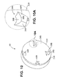
- FIGS. 9 and 10 show four raised elements 26B but may include any number such as 1, 2, 3, 4, 6 or 8 raised elements.
- the raised element 26B is a small wedge of material that rises relatively abruptly from the cup-shaped surface 24B and which subtends an arc of about 1 to 30 degrees relative to axis LA, the four raised elements 26B subtending an arc of about 4 to 60 degrees altogether.
- the raised element 26B has a first wall 30B that extends between a curved cutting edge 50B and cup shaped surface 24B and also has a second wall 32B which extends radially relative to axis LA.
- a third wall 34B extends between the radially inner portion of the first and second walls 30B, 32B.
- the raised elements 26B may occupy a relative small part of the cup-shaped surface 24B and may be recessed from the cutting edge 22B in the manner described above in connection with the cutting element 4.
- at least 60%, 70%, 80% or 90% of the surface area of the cutting element is a smooth cup-shaped surface.
- a distal wall 38B of the cutting element 4B has a surface 40B that forms an angle of less than 90 degrees with respect to the longitudinal axis LA.
- the surface 40B is angled such that edge 50B is more distal than edge 52B.
- the entire surface 40B may still be somewhat close to but recessed from the cutting edge 22B so that the entire surface 40B is from 0.0010 to 0.0050 inch (0.0025 to 0.0127 cm), including 0.0010, 0.0020, 0.0030, 0.0040 or 0.0050 inch (0.0025, 0.0051, 0.0076, 0.0101, or 0.0127 cm), from the cutting edge.
- An edge 50B formed at the intersection of wall 30B and distal wall 38B is closer to the cutting edge 22B than an edge 52B formed at the intersection of wall 32B and distal wall 38B.
- the included angle between wall 30B and surface 40B, in the vicinity of edge 50B, is greater than 90 degrees.
- the cutting element 4B may be rotated in either direction so that the raised edge 50B may be the leading or trailing edge. In one embodiment, the cutter 4B is rotated in the direction of arrow R so that edge 50B is the leading edge.
- Raised edges 50B, 52B may be 0.0010 to 0.0020 inch (0.0025 to 0.0051 cm) from the cutting edge.
- the raised elements 26B may all be formed in the same manner or may be different from one another.
- some of the elements 26B could be angled in different directions so that two of the elements have the raised edge 50B as the leading edge and two of the elements 26A have the raised edge 50B as the trailing edge.
- the raised elements 26B may also subtend different angles, be of different heights or may have different radial lengths without departing from various aspects of the present invention.
- cutter 4B is rotated in the direction of arrow R and pushed distally to force cup shaped surface 24B and raised elements 26B into contact with material such as atheroma or plaque.
- Raised elements 26B will tend to concentrate cutting force along edge 50B due to relief angle between cutter axis LA and surface 40B.
- Cutter 4B will tend to scrape away material such as atheroma or plaque rather than cut into this material due to the obtuse included angle between wall 30B and surface 40B, in the vicinity of edge 50B.
- Material contacted by raised elements 26B will tend to be directed towards axis LA by surface 30B which curves from a relatively tangential angle near edge 22B to a relatively radial angle near edge 34B.
- Cutting element 4C is a modified version of cutting element 4A.
- the modification consists of adding an undercut 41C to the leading face of one or more raised element 26A, resulting in modified raised element 26C.
- the undercut directs particles of material into the concave cavity defined by cup shaped surface 24A of the cutter, and towards axis LA of the cutter.
- an undercut can be applied to the leading face of one or more raised element 26, 26B of cutting elements 4, 4B respectively as well as to one or more raised elements 26A of cutting element 4A.
- Undercut 41C is defined by wall 30C which is oriented at an acute angle to surface 40A, which intersects cup shaped surface 24A, and which meets wall 34A.
- the plane of wall 30C also intersects axis LA at less than 5, 10, 15, or 20 degrees such that, when cutter 4C is spinning in direction T, particles of material tend to travel along wall 30C in directions away from cutting edge 22A and towards axis LA.
- wall 43C may be interspersed between the intersection of wall 30C and wall 40A.
- Wall 43C may be oriented at any desired rake angle, such as for example a negative rake angle where the raised element will tend to not dig in to material being cut.
- the catheter 2 is introduced into the patient in a conventional manner using a guidewire (not shown) or the like.
- the catheter 2 is advanced with the cutting element in the stored position of FIG. 2 until the catheter is positioned proximal to the location where material is to be removed.
- the cutting element 4 is then moved proximally so that the ramp 16 and cam surface 14 engage to move the cutting element 4 to the cutting position of FIG. 3 and to deflect the tip of the catheter 2 to move the cutting element 4 toward the tissue to be cut.
- the cutting element 4 is rotated about longitudinal axis LA and catheter 2 is then moved distally through the vessel so that the cutting element 4 cuts tissue.
- the tissue which has been cut, is directed into the tissue chamber 12 by the cup shaped surface 24, one or more raised elements 26, by curved surface 30B (of cutting element 4B), or by any combination of a cup shaped surface, raised element, or curved surface.
- cutting edge 22B slices softer material and cup shaped surface directs the cut material into tissue chamber 12; the relief angle assures that distally directed force on the catheter is concentrated at raised element edge 50B rather than distributed over surface 40B; raised elements 26B will tend to scrape away or pulverize harder material such as calcium due to the obtuse included angle between wall 30B and surface 40B in the vicinity of edge 50B; curved surface 30B directs material particles towards cutter axis LA; and curved surface 30B when rotating creates a fluid vortex that tends to direct material particles towards cutter axis LA and distally into tissue chamber 12.
- undercut 41C directs material away from cutting edge 22A, along cup shaped surface towards axis LA, and radially towards axis LA of the cutting element.
- FIGS. 12 and 13 show atherectomy catheter 102 having a cutting element 104 that oscillates in a direction generally along axis LA of the cutting element.
- Atherectomy catheter 102 is similar to atherectomy catheter 2 wherein the same or similar reference numbers refer to the same or similar structure and all discussion concerning the same or similar features of the atherectomy catheter 2 are equally applicable here unless noted otherwise.
- Atherectomy catheter 102 is comprised of ramp 116 and cutter 104.
- the cutting element 104 is moved proximally from the stored position ( FIG. 12 ) so that a cam surface 14 on the cutting element 104 engages a ramp 116 on the body 8 of the catheter 102.
- the interaction between the cam surface 14 and the ramp 116 causes the cutting element 104 to move to the cutting position ( FIG. 3 ) and also causes a tip 18 to deflect which tends to move the cutting element 104 toward the tissue to be cut.
- Cutter 104 is comprised of one or more raised portions 14a on cam surface 14; also ramp 116 is comprised of one or more recesses 116a in ramp surface 116b. Recesses and raised portions are relatively dimensioned such that raised portion 14a can fit within recess 116a. Recess 116a is also comprised of at least one edge 116c. Cam surface 14 of cutting element 104 is preloaded into pressured contact against ramp 116.
- catheter 102 is assembled with shaft 20 in tension and catheter body 8 in compression by means known in the art to provide such preload.
- catheter 102 is comprised of a spring (not shown) that forces raised portion 14a against ramp surface 116b.
- Cutter 104 is comprised of cup shaped surface 24 and cutting edge 22 and may be comprised of zero, 1, 2, 3, 4, 6, or 8 raised elements in any mixture or combination of raised elements 26, 26A, 26B, or 26C.
- cutter 104 is comprised of one or more recesses in cam surface 14 and ramp 116 is comprised of one or more raised portions on ramp surface 116b. In yet another embodiment (not shown) cutter 104 is comprised of one or more raised portions on cam surface 14 and ramp 116 is comprised of one or more raised portions on ramp surface 116b.
- catheter 102 is introduced into the patient in a conventional manner using a guidewire (not shown) or the like.
- the catheter 2 is advanced with the cutting element in the stored position of FIG. 12 until the catheter is positioned at the location where material is to be removed.
- the cutting element 104 is then moved proximally so that the ramp 116 and cam surface 14 engage to move the cutting element 104 to the cutting position and to deflect the tip of the catheter 2 to move the cutting element 104 toward the tissue to be cut ( FIG. 3 ).
- the cutting element 104 is rotated about longitudinal axis LA and catheter 102 is then moved distally through the vessel so that the cutting element 104 cuts tissue.
- the tissue, which has been cut is directed into the tissue chamber 12 by cup shaped surface 24.
- An atherectomy catheter comprising:
- the raised element comprises a curved raised element cutting edge.
- the raised element comprises a first wall that extends from the curved raised element cutting edge to the cup-shaped surface, the first wall directing the cut particles of material towards the axis of rotation of the cutting element.
- the raised element comprises a distal wall that extends from the first, curved raised element cutting edge to a second edge, the distal wall forming an angle of less than 90 degrees with respect to the axis of rotation of the cutting element.
- the raised element comprises a first wall that extends from a raised element cutting edge to the cup-shaped surface, the first wall directing the cut particles of material towards the axis of rotation of the cutting element and wherein the first wall forms an acute angle with the cup-shaped surface to form an undercut.
- the raised element comprises a distal wall that extends from the first raised element cutting edge to a second edge, the distal wall forming an angle of less than 90 degrees with respect to the axis of rotation of the cutting element.
- cup-shaped surface of the cutting element has an outer radius when viewed along the axis of rotation of the cutting element, the cup-shaped surface being continuous and uninterrupted from the axis of rotation to at least half the distance to the outer radius.
- the atherectomy catheter described above further comprising a plurality of raised elements, the plurality of raised elements altogether occupying an area less than 60 degrees and less than 5% of the surface area when viewed along the axis of rotation of the cutting element, and the cup-shaped surface being smooth and uninterrupted for at least 90% of the surface area.
- a method of removing material from a body lumen comprising:
- a method of removing material from a body lumen comprising:
Abstract
Description
- This application claims the benefit of
U.S. Provisional Patent Application No. 61/265,863, filed December 2, 2009 - The present invention is directed to cutting elements for an atherectomy catheter and methods of cutting material from a blood flow lumen using a rotating cutting element.
- Catheters are used to remove unwanted tissue from the body. Atherectomy catheters are used to remove material from a blood vessel to open the blood vessel and improve blood flow through the vessel.
- One problem that occurs when removing material from a blood vessel is that the material may be either soft or hard and may vary during the cutting process. As such, the cutting element should be able to cut both hard tissue and soft tissue. Another problem that occurs when using a rotating cutter is that particles of material tend to be displaced in a direction tangential to the cutter, away from the catheter and away from catheter based particle collection structures. It is therefore also desirable to direct cut particles towards the catheter, and especially towards a catheter based particle collection structure.
- The invention provides an atherectomy catheter comprising: a body having an opening; a rotatable shaft coupled to the body; a tissue collection chamber coupled to the body and positioned distal to the cutting element; a cutting element coupled to the rotatable shaft for rotating the cutting element about an axis of rotation, the cutting element having a cup-shaped surface and a cutting edge, the cup-shaped surface being configured to re-direct tissue cut by the cutting edge in a distal direction when the cup-shaped surface moves in the distal direction; and a raised element extending outwardly from the cup-shaped surface of the cutting element, the raised element being configured to direct cut particles of material towards one of more of the axis of rotation of the cutting element, a catheter longitudinal axis, or the tissue collection chamber.
- The invention provides an atherectomy catheter comprising: a body having an opening; a rotatable shaft coupled to the body; a tissue collection chamber coupled to the body and positioned distal to the cutting element; and a cutting element coupled to the rotatable shaft for rotating the cutting element about an axis of rotation, the cutting element having a cutting edge, and the cutting element being configured to oscillate in a direction substantially parallel to the axis of rotation of the cutting element.
- The invention provides a method of removing material from a body lumen, the method comprising providing an atherectomy catheter, the atherectomy catheter comprising: a body having an opening; a rotatable shaft coupled to the body; a tissue collection chamber coupled to the body and positioned distal to the cutting element; a cutting element coupled to the rotatable shaft for rotating the cutting element about an axis of rotation, the cutting element having a cup-shaped surface and a cutting edge, the cup-shaped surface being configured to re-direct tissue cut by the cutting edge in a distal direction when the cup-shaped surface moves in the distal direction; and a raised element extending outwardly from the cup-shaped surface of the cutting element, the raised element being configured to direct cut particles of material towards one of more of the axis of rotation of the cutting element, a catheter longitudinal axis, or the tissue collection chamber; placing the catheter in the body lumen; and moving the catheter in the body lumen to contact the cutting element with the material in the body lumen.
- The invention provides a method of removing material from a body lumen, the method comprising: providing an atherectomy catheter, the atherectomy catheter comprising: a body having an opening; a rotatable shaft coupled to the body; a tissue collection chamber coupled to the body and positioned distal to the cutting element; and a cutting element coupled to the rotatable shaft for rotating the cutting element about an axis of rotation, the cutting element having a cutting edge, and the cutting element being configured to oscillate in a direction substantially parallel to the axis of rotation of the cutting element; placing the catheter in the body lumen; and moving the catheter in the body lumen to contact the cutting element with the material in the body lumen. In one embodiment, the catheter is moved in a distal direction to contact the cutting edge with the material in the body lumen.
- These and other aspects of the invention will become apparent from the following description of the preferred embodiments, drawings and claims. The details of one or more embodiments of the invention are set forth in the accompanying drawings and in the description below. Other features, objects, and advantages of the invention will be apparent from the description and drawings, and from the claims.
-
-
FIG. 1 shows an isometric view of a distal end of an atherectomy catheter. -
FIG. 2 is an isometric cross-sectional view of a portion of the atherectomy catheter ofFIG. 1 with a cutting element in a stored position. -
FIG. 3 is an isometric cross-sectional view of a portion of the atherectomy catheter ofFIG. 1 with a cutting element in a working position. -
FIG. 4 shows an isometric view of an embodiment of a cutting element. -
FIG. 5 shows an end view of an embodiment of a cutting element. -
FIG. 6 is an isometric cross-sectional view of an embodiment of a cutting element. -
FIG. 7 shows an end view of another embodiment of a cutting element, which may be used with the atherectomy catheter shown inFIG. 1 . -
FIG. 8 shows an isometric view of the embodiment of the cutting element illustrated inFIG. 7 . -
FIG. 8A shows an isometric view of one of the raised elements of the cutting element embodiment illustrated inFIG. 8 . -
FIG. 9 shows an end view of another embodiment of a cutting element, which may be used with the atherectomy catheter shown inFIG. 1 . -
FIG. 10 shows an isometric view of the embodiment of the cutting element illustrated inFIG. 9 . -
FIG. 10A shows an isometric view of one of the raised elements of the cutting element embodiment illustrated inFIG. 10 . -
FIG. 11 shows an isometric view of a modified version of the embodiment of the cutting element illustrated inFIG. 8 . -
FIG. 11A shows an isometric view of one of the raised elements of the cutting element embodiment illustrated inFIG. 11 . -
FIG. 12 illustrates an isometric cross-sectional view of a portion of an atherectomy catheter having a cutting element that oscillates in a direction generally along the axis of the cutting element. -
FIG. 13 illustrates an isometric view of a component of the catheter shown inFIG. 12 . - The invention provides an atherectomy catheter comprising: a body having an opening; a rotatable shaft coupled to the body; a tissue collection chamber coupled to the body and positioned distal to the cutting element; a cutting element coupled to the rotatable shaft for rotating the cutting element about an axis of rotation, the cutting element having a cup-shaped surface and a cutting edge, the cup-shaped surface being configured to re-direct tissue cut by the cutting edge in a distal direction when the cup-shaped surface moves in the distal direction; and a raised element extending outwardly from the cup-shaped surface of the cutting element, the raised element being configured to direct cut particles of material towards one of more of the axis of rotation of the cutting element, a catheter longitudinal axis, or the tissue collection chamber. In an embodiment, the raised element is configured to direct cut particles of material towards the axis of rotation of the cutting element. In one embodiment, the cutting edge is at a radially outer edge of the cutting element. In an embodiment, the raised element comprises a curved raised element cutting edge. In an embodiment, the raised element comprises a first wall that extends from the curved raised element cutting edge to the cup-shaped surface, the first wall directing the cut particles of material towards the axis of rotation of the cutting element.
- In an embodiment, the first wall curves from a relatively tangential angle with the cutting edge at the radially outer edge of the cutting element to a relatively radial angle closer to the axis of rotation of the cutting element. In one embodiment, the raised element comprises a distal wall that extends from the first, curved raised element cutting edge to a second edge, the distal wall forming an angle of less than 90 degrees with respect to the axis of rotation of the cutting element. In an embodiment, the first, curved raised element cutting edge is more distal than the second edge. In one embodiment, the minimum radial distance between the first, curved raised element cutting edge and the cutting edge of the cutting element is less than the minimum radial distance between the second edge and the cutting edge of the cutting element. In one embodiment, wherein an included angle between the first wall and the distal wall is an obtuse angle.
- In one embodiment, the raised element is recessed proximally from the cutting edge by a longitudinal distance. For example, the raised element can be recessed proximally from the cutting edge by a longitudinal distance of 0.0010 to 0.0050 inch (0.0025 to 0.0127 cm). In an embodiment, the raised element is recessed from the cutting edge by a radial distance of 0.0010 to 0.0050 inch (0.0025 to 0.0127 cm).
- In one embodiment, the raised element comprises a first wall that extends from a raised element cutting edge to the cup-shaped surface, the first wall directing the cut particles of material towards the axis of rotation of the cutting element and wherein the first wall forms an acute angle with the cup-shaped surface to form an undercut. In an embodiment, the raised element comprises a distal wall that extends from the first raised element cutting edge to a second edge, the distal wall forming an angle of less than 90 degrees with respect to the axis of rotation of the cutting element. In one embodiment, the first raised element cutting edge is more distal than the second edge. In an embodiment, the minimum radial distance between the first raised element cutting edge and the cutting edge of the cutting element is less than the minimum radial distance between the second edge and the cutting edge of the cutting element. In an embodiment, a wall having a rake angle is interspersed between the intersection of the first wall and the distal wall. In one embodiment, the rake angle is negative.
- In an embodiment, the cup-shaped surface of the cutting element is smooth and uninterrupted throughout at least 300 degrees when viewed along the axis of rotation of the cutting element. In one embodiment, the cup-shaped surface of the cutting element is smooth and uninterrupted for at least 90% of the surface area of the cutting element when viewed along the axis of rotation of the cutting element. In an embodiment, the cup-shaped surface of the cutting element has an outer radius when viewed along the axis of rotation of the cutting element, the cup-shaped surface being continuous and uninterrupted from the axis of rotation to at least half the distance to the outer radius. In one embodiment, the atherectomy catheter further comprises a plurality of raised elements, the plurality of raised elements altogether occupying an area less than 60 degrees and less than 5% of the surface area when viewed along the axis of rotation of the cutting element, and the cup-shaped surface being smooth and uninterrupted for at least 90% of the surface area. In one embodiment, the atherectomy catheter comprises a plurality of raised elements extending outwardly from the cup-shaped surface, the plurality of raised elements being 1, 2, 3, 4, 6, or 8 raised elements.
- In one embodiment, the cutting element is movable between a stored position and a cutting position relative to the opening. In an embodiment, the cutting element is moved between the stored position and the cutting position by sliding the cutting element against a cam surface. In an embodiment, a distal portion of the catheter relative to a proximal portion is deflected by sliding the cutting element against the cam surface. In an embodiment, the cutting element is configured to oscillate in a direction substantially parallel to the axis of rotation of the cutting element.
- The invention provides an atherectomy catheter comprising: a body having an opening; a rotatable shaft coupled to the body; a tissue collection chamber coupled to the body and positioned distal to the cutting element; and a cutting element coupled to the rotatable shaft for rotating the cutting element about an axis of rotation, the cutting element having a cutting edge, and the cutting element being configured to oscillate in a direction substantially parallel to the axis of rotation of the cutting element. In one embodiment, the atherectomy catheter comprises a ramp having one or more recesses, the cutting element comprises one or more raised portions on a cam surface of the cutting element, the one or more raised portions fitting within the one or more recesses when the raised portions and the recesses are aligned, and the raised portions leaving and entering the recesses as the cutting element is rotated and thereby causing the cutting element to oscillate. In one embodiment, the atherectomy catheter comprises a ramp having one or more raised portions, the cutting element comprises one or more recesses on a cam surface of the cutting element, the one or more raised portions fitting within the one or more recesses when the raised portions and the recesses are aligned, and the raised portions leaving and entering the recesses as the cutting element is rotated and thereby causing the cutting element to oscillate. In one embodiment, the atherectomy catheter comprises a ramp having one or more raised portions, the cutting element comprises one or more raised portions on a cam surface of the cutting element, and the raised portions causing the cutting element to oscillate as the cutting element is rotated.
- In one embodiment, the cutting element has a cup-shaped surface, the cup-shaped surface being configured to re-direct tissue cut by the cutting edge in a distal direction when the cup-shaped surface moves in the distal direction. In an embodiment, the cutting edge is a radially outer edge of the cutting element. In an embodiment, the catheter comprises a raised element extending outwardly from the cup-shaped surface of the cutting element. In an embodiment, the cutting edge is a radially outer edge of the cutting element, and the raised element is recessed proximally from the cutting edge when viewed along the axis of rotation of the cutting element. In one embodiment, the cutting element is movable between a stored position and a cutting position relative to the opening. In one embodiment, the cutting element is moved between the stored position and the cutting position by sliding the cutting element against a cam surface. In one embodiment, a distal portion of the catheter relative to a proximal portion is deflected by sliding the cutting element against the cam surface.
- The invention provides a method of removing material from a body lumen, the method comprising providing an atherectomy catheter, the atherectomy catheter comprising: a body having an opening; a rotatable shaft coupled to the body; a tissue collection chamber coupled to the body and positioned distal to the cutting element; a cutting element coupled to the rotatable shaft for rotating the cutting element about an axis of rotation, the cutting element having a cup-shaped surface and a cutting edge, the cup-shaped surface being configured to re-direct tissue cut by the cutting edge in a distal direction when the cup-shaped surface moves in the distal direction; and a raised element extending outwardly from the cup-shaped surface of the cutting element, the raised element being configured to direct cut particles of material towards one of more of the axis of rotation of the cutting element, a catheter longitudinal axis, or the tissue collection chamber; placing the catheter in the body lumen; and moving the catheter in the body lumen to contact the cutting element with the material in the body lumen. In one embodiment, the catheter is moved in a distal direction to contact the cutting edge with the material in the body lumen. In one embodiment, the catheter is placed in the body lumen with the cutting element in the stored position and the catheter is moved to contact the material with the cutting element in a cutting position. In one embodiment, the body lumen is a blood vessel.
- The invention provides a method of removing material from a body lumen, the method comprising: providing an atherectomy catheter, the atherectomy catheter comprising: a body having an opening; a rotatable shaft coupled to the body; a tissue collection chamber coupled to the body and positioned distal to the cutting element; and a cutting element coupled to the rotatable shaft for rotating the cutting element about an axis of rotation, the cutting element having a cutting edge, and the cutting element being configured to oscillate in a direction substantially parallel to the axis of rotation of the cutting element; placing the catheter in the body lumen; and moving the catheter in the body lumen to contact the cutting element with the material in the body lumen. In one embodiment, the catheter is moved in a distal direction to contact the cutting edge with the material in the body lumen. In an embodiment, the catheter is placed in the body lumen with the cutting element in the stored position and the catheter is moved to contact the material with the cutting element in a cutting position. In an embodiment, the body lumen is a blood vessel.
- The present invention provides an atherectomy catheter which has a cutting element that is able to cut both soft tissue and hard tissue. The cutting element has a sharp cutting edge that surrounds a cup-shaped surface. The cup-shaped surface directs the material which has been cut into a tissue chamber. The circumferential cutting edge and the cup-shaped surface together are well suited to cut and remove relatively soft tissue.
- In one aspect of the invention, an atherectomy catheter is provided which has one or more raised elements extending from the cup-shaped surface. The raised element may be recessed longitudinally and radially from the outer cutting edge by a controlled distance such as 0.0010-0.0020 inch (0.0025 to 0.0051cm) but may in other embodiments be closer or further from the outer cutting edge depending upon the application. The raised elements help to break up hard tissue such as calcified plaque. The raised elements are somewhat recessed from the distal end so that the cutting edge remains exposed to cut soft tissue. When the cutting element encounters tissue which is too hard to be cut sufficiently by the cutting edge, the raised elements help to break the harder tissue with a more blunt application of force.
- In another aspect of the invention, the raised element is somewhat small so that a relatively large portion of the cup-shaped surface is smooth and uninterrupted. In this manner, the ability of the cutting element to direct tissue into the tissue chamber with the cup-shaped surface is not overly inhibited by the raised elements. For example, the raised elements may occupy an area less than 60 degrees when viewed along the longitudinal axis. Stated another way, the cup-shaped surface of the cutting element is smooth and uninterrupted throughout at least 300 degrees when viewed along the longitudinal axis. Stated still another way, the cup-shaped surface may be smooth and uninterrupted for at least 95% of the surface area of the cutting element when viewed along the longitudinal axis.
- In yet another aspect of the invention, the raised element has a surface that tends to direct cut particles of material towards one or more of the axis of rotation of the cutter, the catheter axis, or a particle collection chamber.
- In further aspects of the invention, the cutter oscillates in a direction roughly parallel to the axis of the cutter so as to impart a force on cut particles of material that directs them in a distal direction, towards a collection chamber, or in both directions.
- Referring to
FIGS. 1 to 4 , anatherectomy catheter 2 is shown which has acutting element 4, which is used to cut material from a blood flow lumen. The cuttingelement 4 is movable between a stored position (FIG. 2 ) and a cutting position (FIG. 3 ) relative to anopening 6 in abody 8 of thecatheter 2. The cuttingelement 8 moves outwardly relative to theopening 6 so that a portion of theelement 4 extends outwardly from thebody 8 through theopening 6. The cuttingelement 4 may be positioned relative to thebody 8 andopening 6 so that less than 90 degrees of the cuttingelement 4 is exposed to cut tissue. Of course, more of the cuttingelement 4 may be exposed without departing from numerous aspects of the invention. -
Catheter 2 may have a maximum size of 3, 4, 5, 6, 7, 8, 9, 10, or 12 French (1, 1.3, 1.7, 2, 2.3, 2.7, 3, 3.3, or 4 mm) and may have a working length ranging of 20, 30, 40, 60, 80, 100, 120, 150, 180 or 210 cm depending on the requirements of the anatomical location in which use of the catheter is contemplated.Cutter 4 preferably has a diameter slightly less than that of the maximum size ofcatheter 2, typically 0.010" (0.025 cm), 0.015" (0.038 cm), 0.020" (0.051 cm), 0.025" (0.064 cm) or 0.030" (0.076 cm) less. However these relative dimensions are not meant to be limiting. - The
catheter 2 is moved distally through a vessel with the cuttingelement 4 in the working or cutting position as described in further detail below. As thecatheter 2 moves through the blood vessel, the tissue is cut by the cuttingelement 4 and is directed into atissue chamber 12 positioned distal to thecutting element 4. Thetissue chamber 12 may be somewhat elongate to accommodate the tissue which has been cut. - The cutting
element 4 is moved proximally from the stored position so that acam surface 14 on thecutting element 4 engages aramp 16 on thebody 8 of thecatheter 2. The interaction between thecam surface 14 and theramp 16 causes thecutting element 4 to move to the cutting position and also causes atip 18 to deflect which tends to move thecutting element 4 toward the tissue to be cut. - The cutting
element 4 is coupled to ashaft 20 that extends through alumen 21 in thecatheter 2. The cuttingelement 4 is rotated about a longitudinal axis LA when the shaft rotates. The cuttingelement 4 is rotated at about 1 to 160,000 rpm but may be rotated at any other suitable speed depending upon the particular application. Referring toFIGS. 2 ,4 and5 , the cuttingelement 4 is shown. The term "along the longitudinal axis" as used herein shall mean the view ofFIG. 5 that shows the distal end of the cuttingelement 4 when viewed in the direction of the longitudinal axis and/or the axis of rotation. The cuttingelement 4 has acutting edge 22 that may be a continuous, uninterrupted, circular-shaped edge although it may also include ridges, teeth, serrations or other features without departing from the scope of the invention. Thecutting edge 22 may be at a radiallyouter edge 23 of the cuttingelement 4 when the cuttingelement 4 is in the cutting position. - The cutting
element 4 has a cup-shapedsurface 24, which directs the tissue cut by thecutting edge 22 into thetissue chamber 12. The cup-shapedsurface 24 may be a smooth and continuous surface free of through-holes, teeth, fins or other features, which disrupt the smooth nature of thesurface 24 for at least half the distance from the longitudinal axis LA to the outer radius at thecutting edge 22. The cup-shapedsurface 24 may also be free of any such features throughout an area of at least 300 degrees relative to the longitudinal axis LA. -
Cutter 4 may be comprised of steel, tungsten carbide, tungsten carbide cobalt, tungsten carbide molybdenum, silicon carbide, silicon nitride, ceramic, amorphous metals or other materials and may be manufactured by methods including turning, grinding, sintering, electro-discharge machining (EDM), laser cutting, heat treating, precipitation hardening, casting or other methods. - Referring to
FIGS. 4 to 6 , one or more raisedelements 26 extend outwardly from the cup-shapedsurface 24 withFIG. 5 showing two raisedelements 26. The raisedelement 26 is a small wedge of material that rises relatively abruptly from the cup-shapedsurface 24. The raisedelement 26 has afirst wall 30 and asecond wall 32 that both extend radially and form an angle of about 20 degrees therebetween so that the two raisedelements 26 together occupy an area of about 40 degrees and altogether may be less than 60 degrees. Athird wall 34 extends between the radially inner portion of the first andsecond walls element 26 helps to break up hard tissue and plaque by applying a relatively blunt force to the hard tissue or plaque since cutting such tissue with thecutting edge 22 is often not effective. - The raised
elements 26 altogether occupy a relatively small part of the cup-shapedsurface 24. The raisedelements 26 together may occupy less than 5% of a surface area of the cuttingelement 4. The term "surface area of the cutting element" as used herein shall mean the surface area which is radially inward from the outer or cuttingedge 22 and is exposed when viewed along the longitudinal axis LA. Stated another way, at least 95% of the surface area of the cutting element is a smooth cup-shaped surface when viewed along the longitudinal axis. By sizing and positioning the raisedelement 26 in this manner, the raisedelement 26 does not interfere with the ability of the cuttingelement 4 to cut and re-direct tissue into the tissue chamber while still providing the ability to break up hard tissue and plaque with the raisedelement 26. - The raised
element 26 may be recessed from thecutting edge 22 longitudinally and/or radially. The raisedelement 26 may be recessed longitudinally (along axis LA) from the cutting edge 0.0010 to 0.0020 inch (0.0025 to 0.0051 cm) and may be recessed about 0.0015 inch (0.0038 cm). The raisedelement 26 may be recessed radially from thecutting edge 22 by about the same amount. Adistal wall 38 of the cuttingelement 4 forms aflat surface 40, which is perpendicular to the longitudinal axis LA so that the entire surface is recessed the same distance from the cutting edge. Thedistal wall 38 may take any other shape, such as a curved shape, or may be tilted, inclined or beveled as now described. - Referring to
FIGS. 7 ,8 and 8A , another cuttingelement 4A is shown wherein the same or similar reference numbers refer to the same or similar structure and all discussion concerning the same or similar features of the cuttingelement 4 are equally applicable here unless noted otherwise. The cuttingelement 4A has acutting edge 22A that may be a continuous, uninterrupted, circular-shaped edge although it may also include ridges, teeth, serrations or other features without departing from the scope of the invention. Thecutting edge 22A may be at a radiallyouter edge 23A of thecutting element 4A when thecutting element 4A is in the cutting position. The cuttingelement 4A has a cup-shapedsurface 24A that directs the tissue cut by thecutting edge 22A into the tissue chamber 12 (seeFIG. 2 ). The cup-shapedsurface 24A may be a substantially smooth and continuous surface as described above in connection with the cuttingelement 4. - One or more raised
elements 26A extend outwardly from the cup-shapedsurface 24A.FIG. 8 shows four raisedelements 26A but may include any number such as 1, 2, 3, 4, 6 or 8 raised elements. The raisedelement 26A is a small wedge of material that rises relatively abruptly from the cup-shapedsurface 24A. The raisedelement 26A has afirst wall 30A and asecond wall 32A which, in one embodiment, both extend radially and form an angle of about 1 to 30 degrees therebetween so that the four raisedelements 26A together occupy an area of about 4 to 60 degrees and altogether may be less than 60 degrees. Athird wall 34A extends between the radially inner portion of the first andsecond walls elements 26A may occupy a relatively small part of the cup-shapedsurface 24A and may be recessed from thecutting edge 22A in the manner described above in connection with the cuttingelement 4. In other embodiments at least 60%, 70%, 80% or 90% of the surface area of the cutting element is a smooth cup-shaped surface. - A
distal wall 38A of thecutting element 4A has asurface 40A that forms an angle of about 30 to 90 degrees with respect to the longitudinal axis LA. Theentire surface 40A may still be somewhat close to but recessed from thecutting edge 22A so that theentire surface 40A is at least 0.0010, 0.0020, 0.0030, 0.0040 or 0.0050 inches (0.0025, 0.0051, 0.0076, 0.0101, or 0.0127 cm) from the cutting edge. Anedge 50 formed at the intersection ofwall 30A anddistal wall 38A is closer to thecutting edge 22A than anedge 52 formed at the intersection ofwall 32A anddistal wall 38A. The cuttingelement 4A may be rotated in either direction so that the raisededge 50 may be the leading or trailing edge. In some embodiments the raised edge may be 0.0010 to 0.0020 inch (0.0025 to 0.0051 cm) from the cutting edge. The raisedelements 26A may all be formed in the same manner or may be different from one another. For example, some of theelements 26A could be angled in different directions so that two of the elements have the raisededge 50 as the leading edge and two of theelements 26A have the raisededge 50 as the trailing edge. The raisedelements 26A may also subtend different angles, be of different heights or may have different radial lengths without departing from various aspects of the present invention. - Referring to
FIGS. 9 ,10 and 10A , another cuttingelement 4B is shown wherein the same or similar reference numbers refer to the same or similar structure and all discussion concerning the same or similar features of the cuttingelement 4 are equally applicable here unless noted otherwise. The cuttingelement 4B has acutting edge 22B that may be a continuous, uninterrupted, circular-shaped edge although it may also include ridges, teeth, serrations or other features without departing from the scope of the invention. Thecutting edge 22B may be at a radiallyouter edge 23B of the cuttingelement 4B when the cuttingelement 4B is in the cutting position. The cuttingelement 4B has a cup-shapedsurface 24B that directs the tissue cut by thecutting edge 22B into the tissue chamber 12 (seeFIG. 2 ). In one embodiment the cup-shapedsurface 24B may be a substantially smooth and continuous surface as described above in connection with the cuttingelement 4. - One or more raised
elements 26B, extend outwardly from the cup-shapedsurface 24B.FIGS. 9 and10 show four raisedelements 26B but may include any number such as 1, 2, 3, 4, 6 or 8 raised elements. The raisedelement 26B is a small wedge of material that rises relatively abruptly from the cup-shapedsurface 24B and which subtends an arc of about 1 to 30 degrees relative to axis LA, the four raisedelements 26B subtending an arc of about 4 to 60 degrees altogether. The raisedelement 26B has afirst wall 30B that extends between acurved cutting edge 50B and cup shapedsurface 24B and also has asecond wall 32B which extends radially relative to axis LA. Athird wall 34B extends between the radially inner portion of the first andsecond walls elements 26B may occupy a relative small part of the cup-shapedsurface 24B and may be recessed from thecutting edge 22B in the manner described above in connection with the cuttingelement 4. In other embodiments at least 60%, 70%, 80% or 90% of the surface area of the cutting element is a smooth cup-shaped surface. - A
distal wall 38B of the cuttingelement 4B has asurface 40B that forms an angle of less than 90 degrees with respect to the longitudinal axis LA. In some embodiments thesurface 40B is angled such thatedge 50B is more distal than edge 52B. Theentire surface 40B may still be somewhat close to but recessed from thecutting edge 22B so that theentire surface 40B is from 0.0010 to 0.0050 inch (0.0025 to 0.0127 cm), including 0.0010, 0.0020, 0.0030, 0.0040 or 0.0050 inch (0.0025, 0.0051, 0.0076, 0.0101, or 0.0127 cm), from the cutting edge. Anedge 50B formed at the intersection ofwall 30B anddistal wall 38B is closer to thecutting edge 22B than an edge 52B formed at the intersection ofwall 32B anddistal wall 38B. The included angle betweenwall 30B andsurface 40B, in the vicinity ofedge 50B, is greater than 90 degrees. The cuttingelement 4B may be rotated in either direction so that the raisededge 50B may be the leading or trailing edge. In one embodiment, thecutter 4B is rotated in the direction of arrow R so thatedge 50B is the leading edge. Raisededges 50B, 52B may be 0.0010 to 0.0020 inch (0.0025 to 0.0051 cm) from the cutting edge. The raisedelements 26B may all be formed in the same manner or may be different from one another. For example, some of theelements 26B could be angled in different directions so that two of the elements have the raisededge 50B as the leading edge and two of theelements 26A have the raisededge 50B as the trailing edge. The raisedelements 26B may also subtend different angles, be of different heights or may have different radial lengths without departing from various aspects of the present invention. - In one
embodiment cutter 4B is rotated in the direction of arrow R and pushed distally to force cup shapedsurface 24B and raisedelements 26B into contact with material such as atheroma or plaque. Raisedelements 26B will tend to concentrate cutting force alongedge 50B due to relief angle between cutter axis LA andsurface 40B.Cutter 4B will tend to scrape away material such as atheroma or plaque rather than cut into this material due to the obtuse included angle betweenwall 30B andsurface 40B, in the vicinity ofedge 50B. Material contacted by raisedelements 26B will tend to be directed towards axis LA bysurface 30B which curves from a relatively tangential angle nearedge 22B to a relatively radial angle nearedge 34B. - Referring to
FIGS. 11 and 11A , another cuttingelement 4C is shown. Cuttingelement 4C is a modified version of cuttingelement 4A. The modification consists of adding an undercut 41C to the leading face of one or more raisedelement 26A, resulting in modified raisedelement 26C. Whencutter 4C is rotated in the direction of arrow T the undercut directs particles of material into the concave cavity defined by cup shapedsurface 24A of the cutter, and towards axis LA of the cutter. Optionally an undercut can be applied to the leading face of one or more raisedelement elements elements 26A of cuttingelement 4A. - Undercut 41C is defined by
wall 30C which is oriented at an acute angle to surface 40A, which intersects cup shapedsurface 24A, and which meetswall 34A. The plane ofwall 30C also intersects axis LA at less than 5, 10, 15, or 20 degrees such that, whencutter 4C is spinning in direction T, particles of material tend to travel alongwall 30C in directions away from cuttingedge 22A and towards axis LA. In someembodiments wall 43C may be interspersed between the intersection ofwall 30C andwall 40A.Wall 43C may be oriented at any desired rake angle, such as for example a negative rake angle where the raised element will tend to not dig in to material being cut. - Use of the
catheter 2 is now described in connection with the cuttingelement 4 but is equally applicable to use of thecatheter 2 with either thecutting element 4A, the cuttingelement 4B, or thecutting element 4C. Thecatheter 2 is introduced into the patient in a conventional manner using a guidewire (not shown) or the like. Thecatheter 2 is advanced with the cutting element in the stored position ofFIG. 2 until the catheter is positioned proximal to the location where material is to be removed. The cuttingelement 4 is then moved proximally so that theramp 16 andcam surface 14 engage to move thecutting element 4 to the cutting position ofFIG. 3 and to deflect the tip of thecatheter 2 to move thecutting element 4 toward the tissue to be cut. The cuttingelement 4 is rotated about longitudinal axis LA andcatheter 2 is then moved distally through the vessel so that the cuttingelement 4 cuts tissue. The tissue, which has been cut, is directed into thetissue chamber 12 by the cup shapedsurface 24, one or more raisedelements 26, bycurved surface 30B (of cuttingelement 4B), or by any combination of a cup shaped surface, raised element, or curved surface. - More specifically, when using cutting
element 4B and rotating the cutting element in the direction of arrow R (FIG. 9 )cutting edge 22B slices softer material and cup shaped surface directs the cut material intotissue chamber 12; the relief angle assures that distally directed force on the catheter is concentrated at raisedelement edge 50B rather than distributed oversurface 40B; raisedelements 26B will tend to scrape away or pulverize harder material such as calcium due to the obtuse included angle betweenwall 30B andsurface 40B in the vicinity ofedge 50B;curved surface 30B directs material particles towards cutter axis LA; andcurved surface 30B when rotating creates a fluid vortex that tends to direct material particles towards cutter axis LA and distally intotissue chamber 12. - More specifically, when using an undercut such as that shown for cutting
element 4C and rotating the cutting element in the direction of arrow T (FIG. 11 ) undercut 41C directs material away from cuttingedge 22A, along cup shaped surface towards axis LA, and radially towards axis LA of the cutting element. - In another embodiment,
FIGS. 12 and13 show atherectomy catheter 102 having a cuttingelement 104 that oscillates in a direction generally along axis LA of the cutting element.Atherectomy catheter 102 is similar toatherectomy catheter 2 wherein the same or similar reference numbers refer to the same or similar structure and all discussion concerning the same or similar features of theatherectomy catheter 2 are equally applicable here unless noted otherwise. -
Atherectomy catheter 102 is comprised oframp 116 andcutter 104. The cuttingelement 104 is moved proximally from the stored position (FIG. 12 ) so that acam surface 14 on thecutting element 104 engages aramp 116 on thebody 8 of thecatheter 102. The interaction between thecam surface 14 and theramp 116 causes thecutting element 104 to move to the cutting position (FIG. 3 ) and also causes atip 18 to deflect which tends to move thecutting element 104 toward the tissue to be cut. -
Cutter 104 is comprised of one or more raisedportions 14a oncam surface 14; also ramp 116 is comprised of one ormore recesses 116a inramp surface 116b. Recesses and raised portions are relatively dimensioned such that raisedportion 14a can fit withinrecess 116a.Recess 116a is also comprised of at least oneedge 116c. Cam surface 14 of cuttingelement 104 is preloaded into pressured contact againstramp 116. In oneembodiment catheter 102 is assembled withshaft 20 in tension andcatheter body 8 in compression by means known in the art to provide such preload. In anotherembodiment catheter 102 is comprised of a spring (not shown) that forces raisedportion 14a againstramp surface 116b.Cutter 104 is comprised of cup shapedsurface 24 and cuttingedge 22 and may be comprised of zero, 1, 2, 3, 4, 6, or 8 raised elements in any mixture or combination of raisedelements - In an alternative embodiment (not shown)
cutter 104 is comprised of one or more recesses incam surface 14 andramp 116 is comprised of one or more raised portions onramp surface 116b. In yet another embodiment (not shown)cutter 104 is comprised of one or more raised portions oncam surface 14 andramp 116 is comprised of one or more raised portions onramp surface 116b. - In
use catheter 102 is introduced into the patient in a conventional manner using a guidewire (not shown) or the like. Thecatheter 2 is advanced with the cutting element in the stored position ofFIG. 12 until the catheter is positioned at the location where material is to be removed. The cuttingelement 104 is then moved proximally so that theramp 116 andcam surface 14 engage to move thecutting element 104 to the cutting position and to deflect the tip of thecatheter 2 to move thecutting element 104 toward the tissue to be cut (FIG. 3 ). The cuttingelement 104 is rotated about longitudinal axis LA andcatheter 102 is then moved distally through the vessel so that the cuttingelement 104 cuts tissue. The tissue, which has been cut, is directed into thetissue chamber 12 by cup shapedsurface 24. While the cuttingelement 104 is rotated about longitudinal axis LA (in, for example, the direction of arrow S) raisedportions 14a will slide alongsurface 116b oframp 116 until the preload ofcutter 104 againstramp 116 causes raisedportion 14a to enter intorecess 116a oframp 116. Further rotation of cuttingelement 104 causes raisedportion 14a to contactrecess edge 116c and be ejected fromrecess 116a oframp 116 thereby producing a hammer-like impact ofcutter 104 against the material to be removed. In the case where the material to be removed has brittle characteristics, the material will be crushed into smaller particles thereby facilitating its removal. Repeated rotation ofcutter 104 will produce repeated hammer-like blows of thecutter 104 against the material to be removed. The oscillations in a direction roughly parallel to the axis of the cutting element impart a force on cut particles of material that directs them in a distal direction, towards a collection chamber, or in both directions. - The above description and the drawings are provided for the purpose of describing embodiments of the invention and are not intended to limit the scope of the invention in any way. It will be apparent to those skilled in the art that various modifications and variations can be made without departing from the spirit or scope of the invention. Thus, it is intended that the present invention cover the modifications and variations of this invention provided they come within the scope of the appended claims and their equivalents. Further, while choices for materials and configurations may have been described above with respect to certain embodiments, one of ordinary skill in the art will understand that the materials and configurations described are applicable across the embodiments.
- An atherectomy catheter comprising:
- a body having an opening;
- a rotatable shaft coupled to the body;
- a tissue collection chamber coupled to the body and positioned distal to the cutting element;
- a cutting element coupled to the rotatable shaft for rotating the cutting element about an axis of rotation, the cutting element having a cup-shaped surface and a cutting edge, the cup-shaped surface being configured to re-direct tissue cut by the cutting edge in a distal direction when the cup-shaped surface moves in the distal direction; and
- a raised element extending outwardly from the cup-shaped surface of the cutting element, the raised element being configured to direct cut particles of material towards one of more of the axis of rotation of the cutting element, a catheter longitudinal axis, or the tissue collection chamber.
- The atherectomy catheter described above, wherein the raised element is configured to direct cut particles of material towards the axis of rotation of the cutting element.
- The atherectomy catheter described above, wherein the cutting edge is at a radially outer edge of the cutting element.
- The atherectomy catheter described above, wherein the raised element comprises a curved raised element cutting edge.
- The atherectomy catheter described above, wherein the raised element comprises a first wall that extends from the curved raised element cutting edge to the cup-shaped surface, the first wall directing the cut particles of material towards the axis of rotation of the cutting element.
- The atherectomy catheter of described above, wherein the first wall curves from a relatively tangential angle with the cutting edge at the radially outer edge of the cutting element to a relatively radial angle closer to the axis of rotation of the cutting element.
- The atherectomy catheter described above, wherein the raised element comprises a distal wall that extends from the first, curved raised element cutting edge to a second edge, the distal wall forming an angle of less than 90 degrees with respect to the axis of rotation of the cutting element.
- The atherectomy catheter described above, wherein the first, curved raised element cutting edge is more distal than the second edge.
- The atherectomy catheter described above, wherein the minimum radial distance between the first, curved raised element cutting edge and the cutting edge of the cutting element is less than the minimum radial distance between the second edge and the cutting edge of the cutting element.
- The atherectomy catheter described above, wherein an included angle between the first wall and the distal wall is an obtuse angle.
- The atherectomy catheter described above, wherein the raised element is recessed proximally from the cutting edge by a longitudinal distance.
- The atherectomy catheter described above, wherein the raised element is recessed proximally from the cutting edge by a longitudinal distance of 0.0010 to 0.0050 inch (0.0025 to 0.0127 cm).
- The atherectomy catheter described above, wherein the raised element is recessed from the cutting edge by a radial distance of 0.0010 to 0.0050 inch (0.0025 to 0.0127 cm).
- The atherectomy catheter described above, wherein the raised element comprises a first wall that extends from a raised element cutting edge to the cup-shaped surface, the first wall directing the cut particles of material towards the axis of rotation of the cutting element and wherein the first wall forms an acute angle with the cup-shaped surface to form an undercut.
- The atherectomy catheter described above, wherein the raised element comprises a distal wall that extends from the first raised element cutting edge to a second edge, the distal wall forming an angle of less than 90 degrees with respect to the axis of rotation of the cutting element.
- The atherectomy catheter described above, wherein the first raised element cutting edge is more distal than the second edge.
- The atherectomy catheter described above, wherein the minimum radial distance between the first raised element cutting edge and the cutting edge of the cutting element is less than the minimum radial distance between the second edge and the cutting edge of the cutting element.
- The atherectomy catheter described above, wherein a wall having a rake angle is interspersed between the intersection of the first wall and the distal wall.
- The atherectomy catheter described above, wherein the rake angle is negative.
- The atherectomy catheter described above, wherein the cup-shaped surface of the cutting element is smooth and uninterrupted throughout at least 300 degrees when viewed along the axis of rotation of the cutting element.
- The atherectomy catheter described above, wherein the cup-shaped surface of the cutting element is smooth and uninterrupted for at least 90% of the surface area of the cutting element when viewed along the axis of rotation of the cutting element.
- The atherectomy catheter described above, wherein the cup-shaped surface of the cutting element has an outer radius when viewed along the axis of rotation of the cutting element, the cup-shaped surface being continuous and uninterrupted from the axis of rotation to at least half the distance to the outer radius.
- The atherectomy catheter described above, further comprising a plurality of raised elements, the plurality of raised elements altogether occupying an area less than 60 degrees and less than 5% of the surface area when viewed along the axis of rotation of the cutting element, and the cup-shaped surface being smooth and uninterrupted for at least 90% of the surface area.
- The atherectomy catheter described above, wherein a plurality of raised elements extend outwardly from the cup-shaped surface, the plurality of raised elements being 1, 2, 3, 4, 6, or 8 raised elements.
- The atherectomy catheter described above, wherein the cutting element is movable between a stored position and a cutting position relative to the opening.
- The atherectomy catheter described above, wherein the cutting element is moved between the stored position and the cutting position by sliding the cutting element against a cam surface.
- The atherectomy catheter described above, wherein a distal portion of the catheter relative to a proximal portion is deflected by sliding the cutting element against the cam surface.
- The atherectomy catheter described above, wherein the cutting element is configured to oscillate in a direction substantially parallel to the axis of rotation of the cutting element.
- A method of removing material from a body lumen, the method comprising:
- providing an atherectomy catheter, the atherectomy catheter comprising:
- a body having an opening;
- a rotatable shaft coupled to the body;
- a tissue collection chamber coupled to the body and positioned distal to the cutting element;
- a cutting element coupled to the rotatable shaft for rotating the cutting element about an axis of rotation, the cutting element having a
- cup-shaped surface and a cutting edge, the cup-shaped surface being configured to re-direct tissue cut by the cutting edge in a distal direction when the cup-shaped surface moves in the distal direction; and
- a raised element extending outwardly from the cup-shaped surface of the cutting element, the raised element being configured to direct cut particles of material towards one of more of the axis of rotation of the cutting element, a catheter longitudinal axis, or the tissue collection chamber;
- placing the catheter in the body lumen; and
- moving the catheter in the body lumen to contact the cutting element with the material in the body lumen.
- The method described above, wherein the catheter is moved in a distal direction to contact the cutting edge with the material in the body lumen.
- The method described above, wherein the catheter is placed in the body lumen with the cutting element in the stored position and the catheter is moved to contact the material with the cutting element in a cutting position.
- The method described above, wherein the body lumen is a blood vessel.
- A method of removing material from a body lumen, the method comprising:
- providing an atherectomy catheter, the atherectomy catheter comprising:
- a body having an opening;
- a rotatable shaft coupled to the body;
- a tissue collection chamber coupled to the body and positioned distal to the cutting element; and
- a cutting element coupled to the rotatable shaft for rotating the cutting element about an axis of rotation, the cutting element having a cutting edge, and the cutting element being configured to oscillate in a direction substantially parallel to the axis of rotation of the cutting element;
- placing the catheter in the body lumen; and
- moving the catheter in the body lumen to contact the cutting element with the material in the body lumen.
- The method described above, wherein the catheter is moved in a distal direction to contact the cutting edge with the material in the body lumen.
- The method described above, wherein the catheter is placed in the body lumen with the cutting element in the stored position and the catheter is moved to contact the material with the cutting element in a cutting position.
- The method described above, wherein the body lumen is a blood vessel.
Claims (13)
- An atherectomy catheter (102) comprising:a body (8) having an opening (16);a rotatable shaft (20) coupled to the body (8);a tissue collection chamber (12) coupled to the body (8) and positioned distal to the cutting element (104); anda cutting element (104) coupled to the rotatable shaft (20) for rotating the cutting element (104) about an axis of rotation, the cutting element (104) having a cutting edge (22), and the cutting element (104) being configured to oscillate in a direction substantially parallel to the axis of rotation of the cutting element (104).
- The atherectomy catheter (102) of claim 1, further comprising a ramp (116) having one or more recesses (116a),
wherein the cutting element (104) comprises one or more raised portions (14a) on a cam surface (14) of the cutting element (104), the one or more raised portions (14a) fitting within the one or more recesses (116a) when the raised portions (14a) and the recesses (116a) are aligned, and the raised portions (14a) leaving and entering the recesses (116a) as the cutting element (104) is rotated and thereby causing the cutting element (104) to oscillate. - The atherectomy catheter (102) of claim 1, further comprising:a ramp (116) having one or more raised portions,wherein the cutting element (104) comprises one or more recesses on a cam surface (14) of the cutting element (104), the one or more raised portions (14a) fitting within the one or more recesses when the raised portions (14a) and the recesses are aligned, and the raised portions (14a) leaving and entering the recesses as the cutting element (104) is rotated and thereby causing the cutting element (104) to oscillate.
- The atherectomy catheter (102) of claim 3, wherein the cam surface (14) of the cutting element (104) preloaded into pressure contact against the ramp (116).
- The atherectomy catheter (102) of claim 1, further comprising:a ramp (116) having one or more raised portions,wherein the cutting element (104) comprises one or more raised portions (14a) on a cam surface (14) of the cutting element (104), and the raised portions (14a) causing the cutting element (104) to oscillate as the cutting element (104) is rotated.
- The atherectomy catheter (102) of claim 5, wherein the cam surface (14) of the cutting element (104) preloaded into pressure contact against the ramp (116).
- The atherectomy catheter (102) of claim 1, wherein the cutting element (104) has a cup-shaped surface (24), the cup-shaped surface (24) being configured to re-direct tissue cut by the cutting edge (22) in a distal direction when the cup-shaped surface (24) moves in the distal direction.
- The atherectomy catheter (102) of claim 7, wherein the cutting edge (22) is a radially outer edge of the cutting element (104).
- The atherectomy catheter (102) of claim 7, wherein the catheter (102) comprises a raised element (26) extending outwardly from the cup-shaped surface (24) of the cutting element (104).
- The atherectomy catheter (102) of claim 9, wherein the cutting edge (22) is a radially outer edge of the cutting element (104), and the raised element (26) is recessed proximally from the cutting edge (22) when viewed along the axis of rotation of the cutting element (104).
- The atherectomy catheter (102) of claim 1, wherein the cutting element (104) is movable between a stored position and a cutting position relative to the opening (6).
- The atherectomy catheter (102) of claim 11, wherein the cutting element (104) is moved between the stored position and the cutting position by sliding the cutting element (104) against a cam surface (14).
- The atherectomy catheter (102) of claim 12, wherein a distal portion of the catheter (102) relative to a proximal portion is deflected by sliding the cutting element (102) against the cam surface (14).
Applications Claiming Priority (2)
| Application Number | Priority Date | Filing Date | Title |
|---|---|---|---|
| US26586309P | 2009-12-02 | 2009-12-02 | |
| EP10788197.1A EP2506783B1 (en) | 2009-12-02 | 2010-12-02 | Methods and devices for cutting tissue |
Related Parent Applications (2)
| Application Number | Title | Priority Date | Filing Date |
|---|---|---|---|
| EP10788197.1A Division EP2506783B1 (en) | 2009-12-02 | 2010-12-02 | Methods and devices for cutting tissue |
| EP10788197.1A Division-Into EP2506783B1 (en) | 2009-12-02 | 2010-12-02 | Methods and devices for cutting tissue |
Publications (2)
| Publication Number | Publication Date |
|---|---|
| EP2913013A1 true EP2913013A1 (en) | 2015-09-02 |
| EP2913013B1 EP2913013B1 (en) | 2016-11-09 |
Family
ID=43646466
Family Applications (2)
| Application Number | Title | Priority Date | Filing Date |
|---|---|---|---|
| EP10788197.1A Active EP2506783B1 (en) | 2009-12-02 | 2010-12-02 | Methods and devices for cutting tissue |
| EP14194521.2A Active EP2913013B1 (en) | 2009-12-02 | 2010-12-02 | Methods and devices for cutting tissue |
Family Applications Before (1)
| Application Number | Title | Priority Date | Filing Date |
|---|---|---|---|
| EP10788197.1A Active EP2506783B1 (en) | 2009-12-02 | 2010-12-02 | Methods and devices for cutting tissue |
Country Status (10)
| Country | Link |
|---|---|
| US (3) | US8496677B2 (en) |
| EP (2) | EP2506783B1 (en) |
| JP (1) | JP5499180B2 (en) |
| KR (1) | KR20120079479A (en) |
| CN (2) | CN104490454A (en) |
| AU (1) | AU2010326063B2 (en) |
| BR (1) | BR112012013389A2 (en) |
| CA (1) | CA2781046C (en) |
| RU (1) | RU2526915C2 (en) |
| WO (1) | WO2011068932A1 (en) |
Families Citing this family (69)
| Publication number | Priority date | Publication date | Assignee | Title |
|---|---|---|---|---|
| US6299622B1 (en) | 1999-08-19 | 2001-10-09 | Fox Hollow Technologies, Inc. | Atherectomy catheter with aligned imager |
| US8328829B2 (en) | 1999-08-19 | 2012-12-11 | Covidien Lp | High capacity debulking catheter with razor edge cutting window |
| US7713279B2 (en) | 2000-12-20 | 2010-05-11 | Fox Hollow Technologies, Inc. | Method and devices for cutting tissue |
| US7708749B2 (en) | 2000-12-20 | 2010-05-04 | Fox Hollow Technologies, Inc. | Debulking catheters and methods |
| ES2436668T3 (en) | 2000-12-20 | 2014-01-03 | Covidien Lp | Catheter to remove atheromatous or thrombotic occlusive material |
| US8246640B2 (en) | 2003-04-22 | 2012-08-21 | Tyco Healthcare Group Lp | Methods and devices for cutting tissue at a vascular location |
| US20070276419A1 (en) | 2006-05-26 | 2007-11-29 | Fox Hollow Technologies, Inc. | Methods and devices for rotating an active element and an energy emitter on a catheter |
| US8784440B2 (en) * | 2008-02-25 | 2014-07-22 | Covidien Lp | Methods and devices for cutting tissue |
| US9498600B2 (en) | 2009-07-01 | 2016-11-22 | Avinger, Inc. | Atherectomy catheter with laterally-displaceable tip |
| US9125562B2 (en) | 2009-07-01 | 2015-09-08 | Avinger, Inc. | Catheter-based off-axis optical coherence tomography imaging system |
| KR101645754B1 (en) | 2008-10-13 | 2016-08-04 | 코비디엔 엘피 | Devices and methods for manipulating a catheter shaft |
| EP2424608B1 (en) | 2009-04-28 | 2014-03-19 | Avinger, Inc. | Guidewire support catheter |
| WO2010126882A1 (en) | 2009-04-29 | 2010-11-04 | Fox Hollow Technologies, Inc. | Methods and devices for cutting and abrading tissue |
| RU2509538C2 (en) | 2009-05-14 | 2014-03-20 | ТАЙКО ХЕЛСКЕА ГРУП эЛПи | Cleanable atherectomy catheters and methods for using them |
| JP6101078B2 (en) | 2009-05-28 | 2017-03-29 | アビンガー・インコーポレイテッドAvinger, Inc. | Optical coherence tomography for bioimaging |
| WO2011068932A1 (en) | 2009-12-02 | 2011-06-09 | Fox Hollow Technologies, Inc. | Methods and devices for cutting tissue |
| WO2011072068A2 (en) | 2009-12-08 | 2011-06-16 | Avinger, Inc. | Devices and methods for predicting and preventing restenosis |
| JP5511107B2 (en) | 2009-12-11 | 2014-06-04 | コヴィディエン リミテッド パートナーシップ | Substance removal device and method with improved substance capture efficiency |
| KR101493138B1 (en) | 2010-06-14 | 2015-02-12 | 코비디엔 엘피 | Material removal device |
| WO2012003430A2 (en) | 2010-07-01 | 2012-01-05 | Avinger, Inc. | Atherectomy catheters with longitudinally displaceable drive shafts |
| US11382653B2 (en) | 2010-07-01 | 2022-07-12 | Avinger, Inc. | Atherectomy catheter |
| EP2632352B1 (en) | 2010-10-28 | 2017-04-12 | Covidien LP | Material removal device |
| CA2817213C (en) | 2010-11-11 | 2016-06-14 | Covidien Lp | Flexible debulking catheters with imaging and methods of use and manufacture |
| EP2691038B1 (en) | 2011-03-28 | 2016-07-20 | Avinger, Inc. | Occlusion-crossing devices, imaging, and atherectomy devices |
| US9949754B2 (en) | 2011-03-28 | 2018-04-24 | Avinger, Inc. | Occlusion-crossing devices |
| WO2013033426A2 (en) | 2011-09-01 | 2013-03-07 | Covidien Lp | Catheter with helical drive shaft and methods of manufacture |
| EP3653151A1 (en) | 2011-10-17 | 2020-05-20 | Avinger, Inc. | Atherectomy catheters and non-contact actuation mechanism for catheters |
| US9345406B2 (en) | 2011-11-11 | 2016-05-24 | Avinger, Inc. | Occlusion-crossing devices, atherectomy devices, and imaging |
| US9351757B2 (en) | 2012-01-17 | 2016-05-31 | Covidien Lp | Material removal device and method of use |
| US11406412B2 (en) | 2012-05-14 | 2022-08-09 | Avinger, Inc. | Atherectomy catheters with imaging |
| US9557156B2 (en) | 2012-05-14 | 2017-01-31 | Avinger, Inc. | Optical coherence tomography with graded index fiber for biological imaging |
| US9345398B2 (en) | 2012-05-14 | 2016-05-24 | Avinger, Inc. | Atherectomy catheter drive assemblies |
| US9498247B2 (en) | 2014-02-06 | 2016-11-22 | Avinger, Inc. | Atherectomy catheters and occlusion crossing devices |
| US11284916B2 (en) | 2012-09-06 | 2022-03-29 | Avinger, Inc. | Atherectomy catheters and occlusion crossing devices |
| JP6523170B2 (en) | 2012-09-06 | 2019-05-29 | アビンガー・インコーポレイテッドAvinger, Inc. | Atheroma catheter and atheroma assembly |
| US10335173B2 (en) | 2012-09-06 | 2019-07-02 | Avinger, Inc. | Re-entry stylet for catheter |
| US9532844B2 (en) | 2012-09-13 | 2017-01-03 | Covidien Lp | Cleaning device for medical instrument and method of use |
| US9943329B2 (en) * | 2012-11-08 | 2018-04-17 | Covidien Lp | Tissue-removing catheter with rotatable cutter |
| WO2014093148A2 (en) | 2012-12-12 | 2014-06-19 | Covidien Lp | Tissue-removing catheter for body lumen |
| JP6110509B2 (en) | 2012-12-12 | 2017-04-05 | コヴィディエン リミテッド パートナーシップ | Tissue removal catheter including pressing mechanism |
| EP2931148B1 (en) | 2012-12-12 | 2016-09-21 | Covidien LP | Cutter for tissue-removing catheter |
| WO2014093068A1 (en) | 2012-12-12 | 2014-06-19 | Covidien Lp | Tissue-removing catheter including screw blade and cutter driveshaft |
| US9636139B2 (en) | 2012-12-12 | 2017-05-02 | Covidien Lp | Tissue-removing catheter with ball and socket deployment mechanism |
| US9636138B2 (en) | 2012-12-12 | 2017-05-02 | Covidien Lp | Tissue-removing catheter including force-transmitting member for actuating a cutter housing |
| WO2014143064A1 (en) | 2013-03-15 | 2014-09-18 | Avinger, Inc. | Chronic total occlusion crossing devices with imaging |
| US10932670B2 (en) | 2013-03-15 | 2021-03-02 | Avinger, Inc. | Optical pressure sensor assembly |
| EP2967507B1 (en) | 2013-03-15 | 2018-09-05 | Avinger, Inc. | Tissue collection device for catheter |
| JP6517198B2 (en) | 2013-07-08 | 2019-05-22 | アビンガー・インコーポレイテッドAvinger, Inc. | Identification of elastic layers guiding interventions |
| US9526519B2 (en) * | 2014-02-03 | 2016-12-27 | Covidien Lp | Tissue-removing catheter with improved angular tissue-removing positioning within body lumen |
| JP6539669B2 (en) | 2014-02-06 | 2019-07-03 | アビンガー・インコーポレイテッドAvinger, Inc. | Atherectomy catheter and crossing obstruction device |
| WO2015200702A1 (en) | 2014-06-27 | 2015-12-30 | Covidien Lp | Cleaning device for catheter and catheter including the same |
| CA2955242A1 (en) | 2014-07-08 | 2016-01-14 | Avinger, Inc. | High speed chronic total occlusion crossing devices |
| CN107530049B (en) * | 2015-02-20 | 2021-06-04 | 皇家飞利浦有限公司 | Atherectomy device with imaging support |
| US10314667B2 (en) | 2015-03-25 | 2019-06-11 | Covidien Lp | Cleaning device for cleaning medical instrument |
| US10905458B2 (en) * | 2015-06-08 | 2021-02-02 | Covidien Lp | Tissue-removing catheter, tissue-removing element, and method of making same |
| US10905459B2 (en) * | 2015-06-08 | 2021-02-02 | Covidien Lp | Tissue-removing catheter, tissue-removing element, and method of making same |
| WO2017011587A1 (en) | 2015-07-13 | 2017-01-19 | Avinger, Inc. | Micro-molded anamorphic reflector lens for image guided therapeutic/diagnostic catheters |
| US10292721B2 (en) | 2015-07-20 | 2019-05-21 | Covidien Lp | Tissue-removing catheter including movable distal tip |
| US10314664B2 (en) | 2015-10-07 | 2019-06-11 | Covidien Lp | Tissue-removing catheter and tissue-removing element with depth stop |
| CA3006045A1 (en) * | 2015-11-25 | 2017-06-01 | George Crawford | Surgical instrumentfor penetration of tissue layers |
| CA3012186A1 (en) | 2016-01-25 | 2017-08-03 | Avinger, Inc. | Oct imaging catheter with lag correction |
| JP6959255B2 (en) | 2016-04-01 | 2021-11-02 | アビンガー・インコーポレイテッドAvinger, Inc. | Catheter device for porridge resection |
| US10456161B2 (en) | 2016-04-14 | 2019-10-29 | Covidien Lp | Tissue-removing catheter with adjustment mechanism |
| US9962180B2 (en) | 2016-04-27 | 2018-05-08 | Covidien Lp | Catheter including drive assembly for rotating and reciprocating tissue-removing element |
| WO2017210466A1 (en) | 2016-06-03 | 2017-12-07 | Avinger, Inc. | Catheter device with detachable distal end |
| EP3478190B1 (en) | 2016-06-30 | 2023-03-15 | Avinger, Inc. | Atherectomy catheter with shapeable distal tip |
| CN109688950B (en) * | 2016-08-30 | 2021-12-07 | 泰尔茂株式会社 | Medical instrument and treatment method |
| US10588656B2 (en) | 2017-11-10 | 2020-03-17 | Penumbra, Inc. | Thrombectomy catheter |
| WO2021076356A1 (en) | 2019-10-18 | 2021-04-22 | Avinger, Inc. | Occlusion-crossing devices |
Citations (3)
| Publication number | Priority date | Publication date | Assignee | Title |
|---|---|---|---|---|
| US5071425A (en) * | 1988-09-12 | 1991-12-10 | Devices For Vascular Intervention, Inc. | Atherectomy catheter and method of forming the same |
| US5250059A (en) * | 1992-01-22 | 1993-10-05 | Devices For Vascular Intervention, Inc. | Atherectomy catheter having flexible nose cone |
| US20090216180A1 (en) * | 2008-02-25 | 2009-08-27 | Fox Hollow Technologies, Inc. | Methods and devices for cutting tissue |
Family Cites Families (586)
| Publication number | Priority date | Publication date | Assignee | Title |
|---|---|---|---|---|
| US1481078A (en) | 1922-11-24 | 1924-01-15 | Albertson & Company | Flexible shafting |
| US2178790A (en) | 1938-05-07 | 1939-11-07 | Abner E Henry | Cutting implement |
| US2701559A (en) | 1951-08-02 | 1955-02-08 | William A Cooper | Apparatus for exfoliating and collecting diagnostic material from inner walls of hollow viscera |
| US2850007A (en) | 1956-05-31 | 1958-09-02 | American Cyanamid Co | Biopsy device |
| US3064651A (en) | 1959-05-26 | 1962-11-20 | Henderson Edward | Hypodermic needle |
| US3082805A (en) | 1960-12-21 | 1963-03-26 | John H Royce | Tissue macerator |
| US3320957A (en) | 1964-05-21 | 1967-05-23 | Sokolik Edward | Surgical instrument |
| GB1235321A (en) | 1968-01-30 | 1971-06-09 | Nat Res Dev | Improvements in or relating to drills for clearing obstructions |
| US3732858A (en) | 1968-09-16 | 1973-05-15 | Surgical Design Corp | Apparatus for removing blood clots, cataracts and other objects from the eye |
| ES152231Y (en) | 1969-10-02 | 1970-07-01 | Ballestero Sierra | A PERFECTED TROCAR. |
| US3683891A (en) | 1970-06-26 | 1972-08-15 | Marshall Eskridge | Tissue auger |
| US3749085A (en) | 1970-06-26 | 1973-07-31 | J Willson | Vascular tissue removing device |
| US3945375A (en) | 1972-04-04 | 1976-03-23 | Surgical Design Corporation | Rotatable surgical instrument |
| SU442795A1 (en) | 1972-04-27 | 1974-09-15 | Л.С. Юхин | Intravascular Surgery Device |
| US3815604A (en) | 1972-06-19 | 1974-06-11 | Malley C O | Apparatus for intraocular surgery |
| US3800783A (en) | 1972-06-22 | 1974-04-02 | K Jamshidi | Muscle biopsy device |
| US3831585A (en) | 1972-07-19 | 1974-08-27 | T Brondy | Retrograde renal biopsy device |
| JPS5042162A (en) | 1973-08-21 | 1975-04-17 | ||
| US3837345A (en) | 1973-08-31 | 1974-09-24 | A Matar | Venous valve snipper |
| JPS5529376B2 (en) | 1973-09-17 | 1980-08-02 | ||
| US3937222A (en) | 1973-11-09 | 1976-02-10 | Surgical Design Corporation | Surgical instrument employing cutter means |
| US3845375A (en) | 1973-11-09 | 1974-10-29 | Mclaughlin Ward & Co | Electronic rotational sensor |
| SU602175A1 (en) * | 1974-06-24 | 1978-04-15 | Киевский научно-исследовательский институт клинической и экспериментальной хирургии | Device for exfoliation of thrombuses and arterosclerotic sequestra |
| US3976077A (en) | 1975-02-03 | 1976-08-24 | Kerfoot Jr Franklin W | Eye surgery device |
| US4007732A (en) | 1975-09-02 | 1977-02-15 | Robert Carl Kvavle | Method for location and removal of soft tissue in human biopsy operations |
| US4038985A (en) | 1975-10-07 | 1977-08-02 | Medico Developments, Inc. | Device for repairing arteries |
| US3995619A (en) | 1975-10-14 | 1976-12-07 | Glatzer Stephen G | Combination subcutaneous suture remover, biopsy sampler and syringe |
| US4030503A (en) | 1975-11-05 | 1977-06-21 | Clark Iii William T | Embolectomy catheter |
| US4020847A (en) | 1975-11-05 | 1977-05-03 | Clark Iii William T | Rotating cutter catheter |
| US4034744A (en) | 1975-11-13 | 1977-07-12 | Smith Kline Instruments, Inc. | Ultrasonic scanning system with video recorder |
| US4177797A (en) | 1977-03-04 | 1979-12-11 | Shelby M. Baylis | Rotary biopsy device and method of using same |
| US4112708A (en) | 1976-06-21 | 1978-09-12 | Nippon Cable Systems Inc. | Flexible drive cable |
| SU665908A1 (en) | 1977-11-09 | 1979-06-05 | Silin Semen A | Device for intravascular surgery |
| US4210146A (en) | 1978-06-01 | 1980-07-01 | Anton Banko | Surgical instrument with flexible blade |
| US4306562A (en) | 1978-12-01 | 1981-12-22 | Cook, Inc. | Tear apart cannula |
| JPS5581633A (en) | 1978-12-15 | 1980-06-19 | Olympus Optical Co | Endoscope |
| US4273128A (en) | 1980-01-14 | 1981-06-16 | Lary Banning G | Coronary cutting and dilating instrument |
| US4306570A (en) | 1980-08-20 | 1981-12-22 | Matthews Larry S | Counter rotating biopsy needle |
| US4368730A (en) | 1981-02-12 | 1983-01-18 | Nigel Sharrock | Intravenous catheter |
| GB2093353B (en) | 1981-02-25 | 1984-09-19 | Dyonics Inc | A surgical instrument for arthroscopic arthroplasty |
| US4436091A (en) | 1981-03-20 | 1984-03-13 | Surgical Design Corporation | Surgical cutting instrument with release mechanism |
| JPS5887494U (en) | 1981-12-05 | 1983-06-14 | 株式会社モリタ製作所 | Speed control device for small medical motors |
| CH660015A5 (en) | 1982-02-01 | 1987-03-13 | Sandoz Ag | PREPARATIONS CONTAINING POLYMER AND SURFACTANTS, THEIR PRODUCTION AND USE. |
| US4445509A (en) | 1982-02-04 | 1984-05-01 | Auth David C | Method and apparatus for removal of enclosed abnormal deposits |
| US4692141A (en) | 1982-03-08 | 1987-09-08 | Mahurkar Sakharam D | Double lumen catheter |
| US4512344A (en) | 1982-05-12 | 1985-04-23 | Barber Forest C | Arthroscopic surgery dissecting apparatus |
| US4424045A (en) | 1982-05-24 | 1984-01-03 | Pennwalt Corporation | Rigid high speed flexible shaft casing assembly for tight radii installations |
| DE3235612A1 (en) | 1982-09-25 | 1984-03-29 | Bayer Ag, 5090 Leverkusen | MICROEMULSIONS |
| US4490139A (en) | 1983-01-28 | 1984-12-25 | Eli Lilly And Company | Implant needle and method |
| US4936987A (en) | 1983-03-07 | 1990-06-26 | Calgon Corporation | Synergistic scale and corrosion inhibiting admixtures containing carboxylic acid/sulfonic acid polymers |
| US4603694A (en) | 1983-03-08 | 1986-08-05 | Richards Medical Company | Arthroscopic shaver |
| US4730616A (en) | 1983-08-12 | 1988-03-15 | Advanced Cardiovascular Systems, Inc. | Multiple probe angioplasty apparatus and method |
| FR2553851B1 (en) | 1983-10-21 | 1988-10-14 | Aubecq Auxi Sa | METHOD FOR MANUFACTURING A PULLEY WITH MULTIPLE V-GROOPS AND PULLEY THUS PRODUCED |
| US5104399A (en) | 1986-12-10 | 1992-04-14 | Endovascular Technologies, Inc. | Artificial graft and implantation method |
| US5669936A (en) | 1983-12-09 | 1997-09-23 | Endovascular Technologies, Inc. | Endovascular grafting system and method for use therewith |
| DE3347671A1 (en) | 1983-12-31 | 1985-07-11 | Richard Wolf Gmbh, 7134 Knittlingen | TISSUE SAMPLING INSTRUMENT |
| US4589412A (en) | 1984-01-03 | 1986-05-20 | Intravascular Surgical Instruments, Inc. | Method and apparatus for surgically removing remote deposits |
| US4631052A (en) | 1984-01-03 | 1986-12-23 | Intravascular Surgical Instruments, Inc. | Method and apparatus for surgically removing remote deposits |
| US4842579B1 (en) | 1984-05-14 | 1995-10-31 | Surgical Systems & Instr Inc | Atherectomy device |
| US4886490A (en) | 1984-05-14 | 1989-12-12 | Surgical Systems & Instruments, Inc. | Atherectomy catheter system and method of using the same |
| US4883458A (en) | 1987-02-24 | 1989-11-28 | Surgical Systems & Instruments, Inc. | Atherectomy system and method of using the same |
| US5007896A (en) | 1988-12-19 | 1991-04-16 | Surgical Systems & Instruments, Inc. | Rotary-catheter for atherectomy |
| US4819634A (en) | 1984-05-14 | 1989-04-11 | Surgical Systems & Instruments | Rotary-catheter for atherectomy system |
| US4979939A (en) | 1984-05-14 | 1990-12-25 | Surgical Systems & Instruments, Inc. | Atherectomy system with a guide wire |
| US4732154A (en) | 1984-05-14 | 1988-03-22 | Surgical Systems & Instruments, Inc. | Rotary catheter system |
| US4894051A (en) | 1984-05-14 | 1990-01-16 | Surgical Systems & Instruments, Inc. | Atherectomy system with a biasing sleeve and method of using the same |
| US4754755A (en) | 1984-05-14 | 1988-07-05 | Husted Royce Hill | Catheter with a rotary blade |
| US5135531A (en) | 1984-05-14 | 1992-08-04 | Surgical Systems & Instruments, Inc. | Guided atherectomy system |
| US5024651A (en) | 1984-05-14 | 1991-06-18 | Surgical Systems & Instruments, Inc. | Atherectomy system with a sleeve |
| US5002553A (en) | 1984-05-14 | 1991-03-26 | Surgical Systems & Instruments, Inc. | Atherectomy system with a clutch |
| US4957482A (en) | 1988-12-19 | 1990-09-18 | Surgical Systems & Instruments, Inc. | Atherectomy device with a positive pump means |
| US4781186A (en) | 1984-05-30 | 1988-11-01 | Devices For Vascular Intervention, Inc. | Atherectomy device having a flexible housing |
| US4926858A (en) | 1984-05-30 | 1990-05-22 | Devices For Vascular Intervention, Inc. | Atherectomy device for severe occlusions |
| US4979951A (en) | 1984-05-30 | 1990-12-25 | Simpson John B | Atherectomy device and method |
| US4646719A (en) | 1984-06-11 | 1987-03-03 | Aries Medical Incorporated | Intra-aortic balloon catheter having flexible torque transmitting tube |
| USRE33258E (en) | 1984-07-23 | 1990-07-10 | Surgical Dynamics Inc. | Irrigating, cutting and aspirating system for percutaneous surgery |
| US4646736A (en) | 1984-09-10 | 1987-03-03 | E. R. Squibb & Sons, Inc. | Transluminal thrombectomy apparatus |
| US4649919A (en) | 1985-01-23 | 1987-03-17 | Precision Surgical Instruments, Inc. | Surgical instrument |
| US4705038A (en) | 1985-01-23 | 1987-11-10 | Dyonics, Inc. | Surgical system for powered instruments |
| US4653496A (en) | 1985-02-01 | 1987-03-31 | Bundy Mark A | Transluminal lysing system |
| US4745919A (en) | 1985-02-01 | 1988-05-24 | Bundy Mark A | Transluminal lysing system |
| US4747406A (en) | 1985-02-13 | 1988-05-31 | Intravascular Surgical Instruments, Inc. | Shaft driven, flexible intravascular recanalization catheter |
| US4686982A (en) | 1985-06-19 | 1987-08-18 | John Nash | Spiral wire bearing for rotating wire drive catheter |
| US4706671A (en) | 1985-05-02 | 1987-11-17 | Weinrib Harry P | Catheter with coiled tip |
| US4594057A (en) | 1985-06-10 | 1986-06-10 | Morgan Products, Inc. | Injector pump |
| US4679558A (en) | 1985-08-12 | 1987-07-14 | Intravascular Surgical Instruments, Inc. | Catheter based surgical methods and apparatus therefor |
| US4664112A (en) | 1985-08-12 | 1987-05-12 | Intravascular Surgical Instruments, Inc. | Catheter based surgical methods and apparatus therefor |
| US4790812A (en) | 1985-11-15 | 1988-12-13 | Hawkins Jr Irvin F | Apparatus and method for removing a target object from a body passsageway |
| US4696298A (en) | 1985-11-19 | 1987-09-29 | Storz Instrument Company | Vitrectomy cutting mechanism |
| US4646738A (en) | 1985-12-05 | 1987-03-03 | Concept, Inc. | Rotary surgical tool |
| CA1293663C (en) | 1986-01-06 | 1991-12-31 | David Christopher Auth | Transluminal microdissection device |
| AU607692B2 (en) | 1986-01-06 | 1991-03-14 | Boston Scientific Corporation Northwest Technology Center, Inc. | Transluminal microdissection device |
| US4669469A (en) | 1986-02-28 | 1987-06-02 | Devices For Vascular Intervention | Single lumen atherectomy catheter device |
| US4794931A (en) | 1986-02-28 | 1989-01-03 | Cardiovascular Imaging Systems, Inc. | Catheter apparatus, system and method for intravascular two-dimensional ultrasonography |
| US5000185A (en) | 1986-02-28 | 1991-03-19 | Cardiovascular Imaging Systems, Inc. | Method for intravascular two-dimensional ultrasonography and recanalization |
| US4771774A (en) | 1986-02-28 | 1988-09-20 | Devices For Vascular Intervention, Inc. | Motor drive unit |
| US4696667A (en) | 1986-03-20 | 1987-09-29 | Helmut Masch | Intravascular catheter and method |
| US4728319A (en) | 1986-03-20 | 1988-03-01 | Helmut Masch | Intravascular catheter |
| US5350395A (en) | 1986-04-15 | 1994-09-27 | Yock Paul G | Angioplasty apparatus facilitating rapid exchanges |
| US4757819A (en) | 1986-05-21 | 1988-07-19 | Olympus Optical Co., Ltd. | Ultrasonic endoscope |
| US4729763A (en) * | 1986-06-06 | 1988-03-08 | Henrie Rodney A | Catheter for removing occlusive material |
| US4765332A (en) | 1986-07-14 | 1988-08-23 | Medinnovations, Inc. | Pullback atherectomy catheter system |
| US4747821A (en) | 1986-10-22 | 1988-05-31 | Intravascular Surgical Instruments, Inc. | Catheter with high speed moving working head |
| US4749376A (en) * | 1986-10-24 | 1988-06-07 | Intravascular Surgical Instruments, Inc. | Reciprocating working head catheter |
| SE455834B (en) | 1986-10-31 | 1988-08-15 | Medinvent Sa | DEVICE FOR TRANSLUMINAL IMPLANTATION OF A PRINCIPLE RODFORMALLY RADIALLY EXPANDABLE PROSTHESIS |
| US4733662A (en) | 1987-01-20 | 1988-03-29 | Minnesota Mining And Manufacturing Company | Tissue gripping and cutting assembly for surgical instrument |
| US4733622A (en) * | 1987-02-24 | 1988-03-29 | Ssmc Inc. | Thread end holder for sewing machine with thread winding bobbin |
| US4923462A (en) | 1987-03-17 | 1990-05-08 | Cordis Corporation | Catheter system having a small diameter rotatable drive member |
| US4846192A (en) | 1987-04-17 | 1989-07-11 | Eastman Kodak Company | Rearwardly acting surgical catheter |
| US4784636A (en) | 1987-04-30 | 1988-11-15 | Schneider-Shiley (U.S.A.) Inc. | Balloon atheroectomy catheter |
| US4817613A (en) | 1987-07-13 | 1989-04-04 | Devices For Vascular Intervention, Inc. | Guiding catheter |
| US4954338A (en) | 1987-08-05 | 1990-09-04 | Rohm And Haas Company | Microbicidal microemulsion |
| US4867157A (en) | 1987-08-13 | 1989-09-19 | Baxter Travenol Laboratories, Inc. | Surgical cutting instrument |
| US4819635A (en) | 1987-09-18 | 1989-04-11 | Henry Shapiro | Tubular microsurgery cutting apparatus |
| DE3732236C1 (en) | 1987-09-24 | 1988-12-15 | Rainer Dr Baumgart | Recanalization catheter |
| US4844064A (en) | 1987-09-30 | 1989-07-04 | Baxter Travenol Laboratories, Inc. | Surgical cutting instrument with end and side openings |
| US5154705A (en) | 1987-09-30 | 1992-10-13 | Lake Region Manufacturing Co., Inc. | Hollow lumen cable apparatus |
| US5165421A (en) | 1987-09-30 | 1992-11-24 | Lake Region Manufacturing Co., Inc. | Hollow lumen cable apparatus |
| US4857046A (en) | 1987-10-21 | 1989-08-15 | Cordis Corporation | Drive catheter having helical pump drive shaft |
| US5047040A (en) | 1987-11-05 | 1991-09-10 | Devices For Vascular Intervention, Inc. | Atherectomy device and method |
| US4870953A (en) | 1987-11-13 | 1989-10-03 | Donmicheal T Anthony | Intravascular ultrasonic catheter/probe and method for treating intravascular blockage |
| US4887613A (en) | 1987-11-23 | 1989-12-19 | Interventional Technologies Inc. | Cutter for atherectomy device |
| NZ222930A (en) | 1987-12-15 | 1990-08-28 | Moffat Appliances Ltd | Gas infra-red burner in heat exchanger |
| US5053044A (en) | 1988-01-11 | 1991-10-01 | Devices For Vascular Intervention, Inc. | Catheter and method for making intravascular incisions |
| US4850957A (en) | 1988-01-11 | 1989-07-25 | American Biomed, Inc. | Atherectomy catheter |
| DE3801318A1 (en) | 1988-01-19 | 1989-07-27 | Stocksmeier Uwe | MEDICAL CATHETER WITH CUTTER |
| US4886061A (en) | 1988-02-09 | 1989-12-12 | Medinnovations, Inc. | Expandable pullback atherectomy catheter system |
| US4899757A (en) | 1988-02-22 | 1990-02-13 | Intertherapy, Inc. | Ultrasound imaging probe with zero dead space |
| DE58906466D1 (en) | 1988-03-04 | 1994-02-03 | Angiomed Ag | Method and device for removing deposits in vessels and organs of living beings. |
| US4838268A (en) | 1988-03-07 | 1989-06-13 | Scimed Life Systems, Inc. | Non-over-the wire balloon catheter |
| US5183432A (en) | 1988-03-19 | 1993-02-02 | Nihonmatai Co., Ltd. | Floating body of sophisticated shape produced from a single sheet of film with a single sealing |
| US5368035A (en) | 1988-03-21 | 1994-11-29 | Boston Scientific Corporation | Ultrasound imaging guidewire |
| US5372138A (en) | 1988-03-21 | 1994-12-13 | Boston Scientific Corporation | Acousting imaging catheters and the like |
| US4935017A (en) | 1988-04-29 | 1990-06-19 | C. R. Bard, Inc. | Variable shaped catheter system and method for catheterization |
| US4950238A (en) | 1988-07-07 | 1990-08-21 | Clarence E. Sikes | Hydro-rotary vascular catheter |
| US4919133A (en) | 1988-08-18 | 1990-04-24 | Chiang Tien Hon | Catheter apparatus employing shape memory alloy structures |
| GB8822149D0 (en) | 1988-09-21 | 1988-10-26 | Ciba Geigy Ag | Treatment of aqueous systems |
| DE8813144U1 (en) | 1988-10-19 | 1988-12-15 | Guenther, Rolf W., Prof. Dr., 5100 Aachen, De | |
| GB8829182D0 (en) | 1988-12-14 | 1989-01-25 | Univ Birmingham | Surgical instrument |
| DE8900059U1 (en) | 1989-01-04 | 1989-05-24 | Schneider (Europe) Ag, Zuerich, Ch | |
| AU4945490A (en) | 1989-01-06 | 1990-08-01 | Angioplasty Systems Inc. | Electrosurgical catheter for resolving atherosclerotic plaque |
| US4986807A (en) | 1989-01-23 | 1991-01-22 | Interventional Technologies, Inc. | Atherectomy cutter with radially projecting blade |
| US4966604A (en) | 1989-01-23 | 1990-10-30 | Interventional Technologies Inc. | Expandable atherectomy cutter with flexibly bowed blades |
| US5077506A (en) | 1989-02-03 | 1991-12-31 | Dyonics, Inc. | Microprocessor controlled arthroscopic surgical system |
| US5087265A (en) | 1989-02-17 | 1992-02-11 | American Biomed, Inc. | Distal atherectomy catheter |
| US4994067A (en) | 1989-02-17 | 1991-02-19 | American Biomed, Inc. | Distal atherectomy catheter |
| US5431673A (en) | 1989-02-17 | 1995-07-11 | American Biomed, Inc. | Distal atherectomy catheter |
| US4928693A (en) | 1989-03-13 | 1990-05-29 | Schneider (Usa), Inc. | Pressure monitor catheter |
| US5078723A (en) | 1989-05-08 | 1992-01-07 | Medtronic, Inc. | Atherectomy device |
| DE59010156D1 (en) | 1989-06-01 | 1996-04-04 | Schneider Europ Ag | Catheter arrangement with a guide wire and method for producing such a guide wire |
| US5029588A (en) | 1989-06-15 | 1991-07-09 | Cardiovascular Imaging Systems, Inc. | Laser catheter with imaging capability |
| US5226910A (en) | 1989-07-05 | 1993-07-13 | Kabushiki Kaisha Topcon | Surgical cutter |
| US5269793A (en) | 1989-07-20 | 1993-12-14 | Devices For Vascular Intervention, Inc. | Guide wire systems for intravascular catheters |
| US5100426A (en) | 1989-07-26 | 1992-03-31 | Fts Engineering, Inc. | Catheter for performing an atherectomy procedure |
| US5282484A (en) | 1989-08-18 | 1994-02-01 | Endovascular Instruments, Inc. | Method for performing a partial atherectomy |
| US5115814A (en) | 1989-08-18 | 1992-05-26 | Intertherapy, Inc. | Intravascular ultrasonic imaging probe and methods of using same |
| US5211651A (en) | 1989-08-18 | 1993-05-18 | Evi Corporation | Catheter atherotome |
| US5226909A (en) | 1989-09-12 | 1993-07-13 | Devices For Vascular Intervention, Inc. | Atherectomy device having helical blade and blade guide |
| US4997435A (en) | 1989-09-25 | 1991-03-05 | Methodist Hospital Of Indiana Inc. | Percutaneous catheter with encapsulating receptacle |
| US5092839A (en) | 1989-09-29 | 1992-03-03 | Kipperman Robert M | Coronary thrombectomy |
| US5116352A (en) | 1989-10-06 | 1992-05-26 | Angiomed Ag | Apparatus for removing deposits from vessels |
| US5049124A (en) | 1989-10-14 | 1991-09-17 | Dow Corning Wright Corporation | Catheter drive apparatus having fluid delivery bearing |
| US5024234A (en) | 1989-10-17 | 1991-06-18 | Cardiovascular Imaging Systems, Inc. | Ultrasonic imaging catheter with guidewire channel |
| US5009659A (en) | 1989-10-30 | 1991-04-23 | Schneider (Usa) Inc. | Fiber tip atherectomy catheter |
| CA2028223C (en) | 1989-11-02 | 2000-11-14 | Jemin Charles Hsu | Synergistic microbicidal combinations containing 4,5-dichloro-2-octyl-3-isothiazolone and certain commercial biocides |
| US5505210A (en) | 1989-11-06 | 1996-04-09 | Mectra Labs, Inc. | Lavage with tissue cutting cannula |
| US5019088A (en) | 1989-11-07 | 1991-05-28 | Interventional Technologies Inc. | Ovoid atherectomy cutter |
| US5026384A (en) | 1989-11-07 | 1991-06-25 | Interventional Technologies, Inc. | Atherectomy systems and methods |
| US5085662A (en) | 1989-11-13 | 1992-02-04 | Scimed Life Systems, Inc. | Atherectomy catheter and related components |
| US5030201A (en) | 1989-11-24 | 1991-07-09 | Aubrey Palestrant | Expandable atherectomy catheter device |
| US5178625A (en) | 1989-12-07 | 1993-01-12 | Evi Corporation | Catheter atherotome |
| US5011490A (en) | 1989-12-07 | 1991-04-30 | Medical Innovative Technologies R&D Limited Partnership | Endoluminal tissue excision catheter system and method |
| US5003918A (en) | 1989-12-28 | 1991-04-02 | Interventional Technologies, Inc. | Apparatus for manufacturing atherectomy torque tubes |
| US5120323A (en) | 1990-01-12 | 1992-06-09 | Schneider (Usa) Inc. | Telescoping guide catheter system |
| US5916210A (en) | 1990-01-26 | 1999-06-29 | Intraluminal Therapeutics, Inc. | Catheter for laser treatment of atherosclerotic plaque and other tissue abnormalities |
| US5074841A (en) | 1990-01-30 | 1991-12-24 | Microcision, Inc. | Atherectomy device with helical cutter |
| US5152744A (en) | 1990-02-07 | 1992-10-06 | Smith & Nephew Dyonics | Surgical instrument |
| US5084010A (en) | 1990-02-20 | 1992-01-28 | Devices For Vascular Intervention, Inc. | System and method for catheter construction |
| US5092873A (en) | 1990-02-28 | 1992-03-03 | Devices For Vascular Intervention, Inc. | Balloon configuration for atherectomy catheter |
| US5222966A (en) | 1990-02-28 | 1993-06-29 | Devices For Vascular Intervention, Inc. | Balloon connection and inflation lumen for atherectomy catheter |
| US5366463A (en) | 1990-05-02 | 1994-11-22 | Ryan William J | Atherectomy catheter for the removal of atherosclerosis from within blood vessels |
| US5267955A (en) | 1990-05-10 | 1993-12-07 | Lake Region Manufacturing Company, Inc. | Atherectomy device |
| US5154724A (en) | 1990-05-14 | 1992-10-13 | Andrews Winston A | Atherectomy catheter |
| US5395311A (en) | 1990-05-14 | 1995-03-07 | Andrews; Winston A. | Atherectomy catheter |
| US5095911A (en) | 1990-05-18 | 1992-03-17 | Cardiovascular Imaging Systems, Inc. | Guidewire with imaging capability |
| US5558093A (en) | 1990-05-18 | 1996-09-24 | Cardiovascular Imaging Systems, Inc. | Guidewire with imaging capability |
| US5100424A (en) | 1990-05-21 | 1992-03-31 | Cardiovascular Imaging Systems, Inc. | Intravascular catheter having combined imaging abrasion head |
| US5674232A (en) | 1990-06-05 | 1997-10-07 | Halliburton; Alexander George | Catheter and method of use thereof |
| US5181920A (en) | 1990-06-08 | 1993-01-26 | Devices For Vascular Intervention, Inc. | Atherectomy device with angioplasty balloon and method |
| US5527298A (en) | 1990-06-11 | 1996-06-18 | Schneider (Usa) Inc. | Tracking guidewire |
| US5360443A (en) | 1990-06-11 | 1994-11-01 | Barone Hector D | Aortic graft for repairing an abdominal aortic aneurysm |
| JPH06114070A (en) | 1990-06-22 | 1994-04-26 | Vance Prod Inc | Tissue abscission device for surgery |
| US5064435A (en) | 1990-06-28 | 1991-11-12 | Schneider (Usa) Inc. | Self-expanding prosthesis having stable axial length |
| US5520189A (en) | 1990-07-13 | 1996-05-28 | Coraje, Inc. | Intravascular ultrasound imaging guidewire |
| CA2048120A1 (en) | 1990-08-06 | 1992-02-07 | William J. Drasler | Thrombectomy method and device |
| US5078722A (en) | 1990-08-14 | 1992-01-07 | Cordis Corporation | Method and apparatus for removing deposits from a vessel |
| US5100423A (en) | 1990-08-21 | 1992-03-31 | Medical Engineering & Development Institute, Inc. | Ablation catheter |
| US5127902A (en) | 1990-09-05 | 1992-07-07 | Medical Innovative Technologies R&D Limited Partnership | Apparatus and method for precisely controlling the excision of obstructive tissue in a human blood vessel |
| US5250065A (en) | 1990-09-11 | 1993-10-05 | Mectra Labs, Inc. | Disposable lavage tip assembly |
| US5114399A (en) | 1990-10-01 | 1992-05-19 | Intramed Laboratories | Surgical device |
| US5190528A (en) | 1990-10-19 | 1993-03-02 | Boston University | Percutaneous transseptal left atrial cannulation system |
| US5242460A (en) | 1990-10-25 | 1993-09-07 | Devices For Vascular Intervention, Inc. | Atherectomy catheter having axially-disposed cutting edge |
| US5527292A (en) | 1990-10-29 | 1996-06-18 | Scimed Life Systems, Inc. | Intravascular device for coronary heart treatment |
| US5496267A (en) | 1990-11-08 | 1996-03-05 | Possis Medical, Inc. | Asymmetric water jet atherectomy |
| DE4036570A1 (en) | 1990-11-16 | 1992-05-21 | Osypka Peter | CATHETER FOR REDUCING OR REMOVING CONSTRUCTIONS IN VESSELS |
| JP2550778B2 (en) | 1990-11-30 | 1996-11-06 | 富士写真光機株式会社 | Ultrasonic inspection equipment |
| US5108500A (en) | 1990-12-10 | 1992-04-28 | Rohm And Haas Company | Stabilization of water insoluble 3-isothiazolones |
| US5112345A (en) | 1990-12-17 | 1992-05-12 | Interventional Technologies | Atherectomy cutter with arcuate blades |
| US5054492A (en) | 1990-12-17 | 1991-10-08 | Cardiovascular Imaging Systems, Inc. | Ultrasonic imaging catheter having rotational image correlation |
| US5110822A (en) | 1991-01-03 | 1992-05-05 | Rohm And Haas Company | Synergistic combinations of 4,5-dichloro-2-n-octyl-3-isothiazolone or 2-methyl-3-isothiazolone with ferric dimethyl dithiocarbamate fungicide |
| EP0525176A4 (en) | 1991-02-19 | 1994-07-13 | Fischell Robert | Improved apparatus and method for atherectomy |
| US5445155A (en) | 1991-03-13 | 1995-08-29 | Scimed Life Systems Incorporated | Intravascular imaging apparatus and methods for use and manufacture |
| US5295958A (en) | 1991-04-04 | 1994-03-22 | Shturman Cardiology Systems, Inc. | Method and apparatus for in vivo heart valve decalcification |
| CA2202800A1 (en) | 1991-04-11 | 1992-10-12 | Alec A. Piplani | Endovascular graft having bifurcation and apparatus and method for deploying the same |
| US6501551B1 (en) | 1991-04-29 | 2002-12-31 | Massachusetts Institute Of Technology | Fiber optic imaging endoscope interferometer with at least one faraday rotator |
| US6134003A (en) | 1991-04-29 | 2000-10-17 | Massachusetts Institute Of Technology | Method and apparatus for performing optical measurements using a fiber optic imaging guidewire, catheter or endoscope |
| EP0581871B2 (en) | 1991-04-29 | 2009-08-12 | Massachusetts Institute Of Technology | Apparatus for optical imaging and measurement |
| IT1249059B (en) | 1991-05-22 | 1995-02-11 | Rosa Antonio | ULTRASONIC DISSECTOR-DISCONNECTOR OF ATEROSCLEROTIC PLATES |
| US5395335A (en) | 1991-05-24 | 1995-03-07 | Jang; G. David | Universal mode vascular catheter system |
| US5284486A (en) | 1991-06-11 | 1994-02-08 | Microvena Corporation | Self-centering mechanical medical device |
| US5569275A (en) | 1991-06-11 | 1996-10-29 | Microvena Corporation | Mechanical thrombus maceration device |
| US5263928A (en) | 1991-06-14 | 1993-11-23 | Baxter International Inc. | Catheter and endoscope assembly and method of use |
| US5273526A (en) | 1991-06-21 | 1993-12-28 | Lake Region Manufacturing Company, Inc. | Vascular occulusion removal devices and method |
| US5217474A (en) | 1991-07-15 | 1993-06-08 | Zacca Nadim M | Expandable tip atherectomy method and apparatus |
| US5242461A (en) | 1991-07-22 | 1993-09-07 | Dow Corning Wright | Variable diameter rotating recanalization catheter and surgical method |
| US5336167A (en) | 1991-07-22 | 1994-08-09 | Theratek International, Inc. | Controller for intravascular catheter system |
| US5261877A (en) | 1991-07-22 | 1993-11-16 | Dow Corning Wright | Method of performing a thrombectomy procedure |
| JPH0542162A (en) | 1991-08-15 | 1993-02-23 | Nissho Corp | Embolus excision catheter |
| JP3084830B2 (en) | 1991-08-29 | 2000-09-04 | 株式会社ニッショー | Embolectomy catheter |
| US5377682A (en) | 1991-09-05 | 1995-01-03 | Matsushita Electric Industrial Co., Ltd. | Ultrasonic probe for transmission and reception of ultrasonic wave and ultrasonic diagnostic apparatus including ultrasonic probe |
| US5285795A (en) | 1991-09-12 | 1994-02-15 | Surgical Dynamics, Inc. | Percutaneous discectomy system having a bendable discectomy probe and a steerable cannula |
| US5423846A (en) | 1991-10-21 | 1995-06-13 | Cathco, Inc. | Dottering auger catheter system |
| US5263959A (en) | 1991-10-21 | 1993-11-23 | Cathco, Inc. | Dottering auger catheter system and method |
| EP0539237A1 (en) | 1991-10-25 | 1993-04-28 | Cook Incorporated | Expandable transluminal graft prosthesis for repair of aneurysm and method for implanting |
| JPH0775611A (en) | 1991-12-05 | 1995-03-20 | Daitoubou Shinsou Kk | Pillow |
| US5316023A (en) | 1992-01-08 | 1994-05-31 | Expandable Grafts Partnership | Method for bilateral intra-aortic bypass |
| US5192291A (en) | 1992-01-13 | 1993-03-09 | Interventional Technologies, Inc. | Rotationally expandable atherectomy cutter assembly |
| US5224945A (en) | 1992-01-13 | 1993-07-06 | Interventional Technologies, Inc. | Compressible/expandable atherectomy cutter |
| US5224949A (en) | 1992-01-13 | 1993-07-06 | Interventional Technologies, Inc. | Camming device |
| DE69225812T2 (en) | 1992-01-13 | 1998-10-01 | Schneider Usa Inc | CUTTING DEVICE FOR ATHEREECTOMY CATHETER |
| ATE150953T1 (en) | 1992-01-13 | 1997-04-15 | Schneider Usa Inc | SURGICAL CUTTING INSTRUMENT |
| US5318032A (en) | 1992-02-05 | 1994-06-07 | Devices For Vascular Intervention | Guiding catheter having soft tip |
| WO1993016642A1 (en) | 1992-02-21 | 1993-09-02 | Boston Scientific Corporation | Ultrasound imaging guidewire |
| US5295493A (en) | 1992-03-19 | 1994-03-22 | Interventional Technologies, Inc. | Anatomical guide wire |
| US5350390A (en) | 1992-03-25 | 1994-09-27 | Arieh Sher | Device for removal of intraluminal occlusions |
| US5176693A (en) | 1992-05-11 | 1993-01-05 | Interventional Technologies, Inc. | Balloon expandable atherectomy cutter |
| US5269759A (en) | 1992-07-28 | 1993-12-14 | Cordis Corporation | Magnetic guidewire coupling for vascular dilatation apparatus |
| US5306294A (en) | 1992-08-05 | 1994-04-26 | Ultrasonic Sensing And Monitoring Systems, Inc. | Stent construction of rolled configuration |
| US5707376A (en) | 1992-08-06 | 1998-01-13 | William Cook Europe A/S | Stent introducer and method of use |
| US5224488A (en) | 1992-08-31 | 1993-07-06 | Neuffer Francis H | Biopsy needle with extendable cutting means |
| US5383460A (en) | 1992-10-05 | 1995-01-24 | Cardiovascular Imaging Systems, Inc. | Method and apparatus for ultrasound imaging and atherectomy |
| US5360432A (en) | 1992-10-16 | 1994-11-01 | Shturman Cardiology Systems, Inc. | Abrasive drive shaft device for directional rotational atherectomy |
| US5356418A (en) | 1992-10-28 | 1994-10-18 | Shturman Cardiology Systems, Inc. | Apparatus and method for rotational atherectomy |
| US5312427A (en) | 1992-10-16 | 1994-05-17 | Shturman Cardiology Systems, Inc. | Device and method for directional rotational atherectomy |
| US5531690A (en) | 1992-10-30 | 1996-07-02 | Cordis Corporation | Rapid exchange catheter |
| US5336178A (en) | 1992-11-02 | 1994-08-09 | Localmed, Inc. | Intravascular catheter with infusion array |
| US5571122A (en) | 1992-11-09 | 1996-11-05 | Endovascular Instruments, Inc. | Unitary removal of plaque |
| US5643297A (en) | 1992-11-09 | 1997-07-01 | Endovascular Instruments, Inc. | Intra-artery obstruction clearing apparatus and methods |
| US5540707A (en) | 1992-11-13 | 1996-07-30 | Scimed Life Systems, Inc. | Expandable intravascular occlusion material removal devices and methods of use |
| US5792157A (en) | 1992-11-13 | 1998-08-11 | Scimed Life Systems, Inc. | Expandable intravascular occlusion material removal devices and methods of use |
| US5501694A (en) | 1992-11-13 | 1996-03-26 | Scimed Life Systems, Inc. | Expandable intravascular occlusion material removal devices and methods of use |
| US5372602A (en) | 1992-11-30 | 1994-12-13 | Device For Vascular Intervention, Inc. | Method of removing plaque using catheter cutter with torque control |
| CA2150707A1 (en) | 1992-12-01 | 1994-06-09 | Mir A. Imram | Vibratory element for crossing stenoses |
| US5584842A (en) | 1992-12-02 | 1996-12-17 | Intramed Laboratories, Inc. | Valvulotome and method of using |
| US5318576A (en) | 1992-12-16 | 1994-06-07 | Plassche Jr Walter M | Endovascular surgery systems |
| US5373849A (en) | 1993-01-19 | 1994-12-20 | Cardiovascular Imaging Systems, Inc. | Forward viewing imaging catheter |
| DE69409565T2 (en) | 1993-01-29 | 1998-10-01 | Smith & Nephew Inc | Swiveling curved instrument |
| US5620447A (en) | 1993-01-29 | 1997-04-15 | Smith & Nephew Dyonics Inc. | Surgical instrument |
| DE9303531U1 (en) | 1993-03-11 | 1994-07-14 | Redha Falah | Medical instrument |
| US5378234A (en) | 1993-03-15 | 1995-01-03 | Pilot Cardiovascular Systems, Inc. | Coil polymer composite |
| CH685738A5 (en) | 1993-03-25 | 1995-09-29 | Ferromec Sa | Medical instrument for removing deposits formed on the inner walls of the arteries or veins. |
| US5372601A (en) | 1993-03-30 | 1994-12-13 | Lary; Banning G. | Longitudinal reciprocating incisor |
| US5322508A (en) | 1993-04-08 | 1994-06-21 | Cordis Corporation | Guidewire fluid delivery system and method of use |
| US5318528A (en) | 1993-04-13 | 1994-06-07 | Advanced Surgical Inc. | Steerable surgical devices |
| US5429136A (en) | 1993-04-21 | 1995-07-04 | Devices For Vascular Intervention, Inc. | Imaging atherectomy apparatus |
| US5716410A (en) | 1993-04-30 | 1998-02-10 | Scimed Life Systems, Inc. | Temporary stent and method of use |
| US5456667A (en) | 1993-05-20 | 1995-10-10 | Advanced Cardiovascular Systems, Inc. | Temporary stenting catheter with one-piece expandable segment |
| WO1994027501A1 (en) | 1993-05-24 | 1994-12-08 | Boston Scientific Corporation | Medical acoustic imaging catheter and guidewire |
| US5531685A (en) | 1993-06-11 | 1996-07-02 | Catheter Research, Inc. | Steerable variable stiffness device |
| CA2166466C (en) | 1993-07-03 | 2002-02-05 | Michael Ralph Rees | Improvements in or relating to angioplasty |
| US5514115A (en) | 1993-07-07 | 1996-05-07 | Device For Vascular Intervention, Inc. | Flexible housing for intracorporeal use |
| US5527325A (en) | 1993-07-09 | 1996-06-18 | Device For Vascular Intervention, Inc. | Atherectomy catheter and method |
| US5419774A (en) | 1993-07-13 | 1995-05-30 | Scimed Life Systems, Inc. | Thrombus extraction device |
| US5458585A (en) | 1993-07-28 | 1995-10-17 | Cardiovascular Imaging Systems, Inc. | Tracking tip for a work element in a catheter system |
| US5395313A (en) | 1993-08-13 | 1995-03-07 | Naves; Neil H. | Reciprocating arthroscopic shaver |
| US5441510A (en) | 1993-09-01 | 1995-08-15 | Technology Development Center | Bi-axial cutter apparatus for catheter |
| US5573008A (en) | 1993-10-29 | 1996-11-12 | Boston Scientific Corporation | Multiple biopsy sampling coring device |
| US5444078A (en) | 1993-10-01 | 1995-08-22 | Rohm And Haas Company | Fully water-dilutable microemulsions |
| US5456689A (en) | 1993-10-13 | 1995-10-10 | Arnold J. Kresch | Method and device for tissue resection |
| DE4335931B4 (en) | 1993-10-21 | 2006-10-12 | Cerasiv Gmbh Innovatives Keramik-Engineering | acetabulum |
| AU1091095A (en) | 1993-11-08 | 1995-05-29 | Harrison M. Lazarus | Intraluminal vascular graft and method |
| US5507760A (en) * | 1993-11-09 | 1996-04-16 | Devices For Vascular Intervention, Inc. | Cutter device |
| US5443497A (en) | 1993-11-22 | 1995-08-22 | The Johns Hopkins University | Percutaneous prosthetic by-pass graft and method of use |
| US5427107A (en) | 1993-12-07 | 1995-06-27 | Devices For Vascular Intervention, Inc. | Optical encoder for catheter device |
| AU1399995A (en) | 1993-12-09 | 1995-06-27 | Devices For Vascular Intervention, Inc. | Composite drive shaft |
| US5503155A (en) | 1994-01-26 | 1996-04-02 | Cardiovascular Imaging Systems, Inc. | Drive cable having internal lead wires |
| US5591127A (en) | 1994-01-28 | 1997-01-07 | Barwick, Jr.; Billie J. | Phacoemulsification method and apparatus |
| US5507769A (en) | 1994-10-18 | 1996-04-16 | Stentco, Inc. | Method and apparatus for forming an endoluminal bifurcated graft |
| US5413107A (en) | 1994-02-16 | 1995-05-09 | Tetrad Corporation | Ultrasonic probe having articulated structure and rotatable transducer head |
| US5485840A (en) | 1994-03-15 | 1996-01-23 | Bauman; Robert P. | Method of precise guidance for directional atherectomy using ultrasound |
| US5624457A (en) | 1994-04-07 | 1997-04-29 | Devices For Vascular Intervention | Directional atherectomy device with flexible housing |
| US5507795A (en) | 1994-04-29 | 1996-04-16 | Devices For Vascular Intervention, Inc. | Catheter with perfusion system |
| US5569279A (en) | 1994-04-29 | 1996-10-29 | Rainin; Edgar A. | Surgical abrading device |
| US5466382A (en) | 1994-05-03 | 1995-11-14 | Rohm And Haas Company | Synergistic microbicidal combinations containing 4,5-dichloro-2-n-octyl-3-isothiazolone and certain commercial biocides |
| USRE38335E1 (en) | 1994-05-24 | 2003-11-25 | Endius Incorporated | Surgical instrument |
| US5628761A (en) | 1994-07-08 | 1997-05-13 | Rizik; David G. | Guide wire passage creation device |
| US5531700A (en) | 1994-07-29 | 1996-07-02 | Cardiovascular Imaging Systems, Inc. | Convertible tip catheters and sheaths |
| US5575817A (en) | 1994-08-19 | 1996-11-19 | Martin; Eric C. | Aorto femoral bifurcation graft and method of implantation |
| US5609605A (en) | 1994-08-25 | 1997-03-11 | Ethicon, Inc. | Combination arterial stent |
| WO1996010366A1 (en) | 1994-10-03 | 1996-04-11 | Heart Technology, Inc. | Transluminal thrombectomy apparatus |
| US5571130A (en) | 1994-10-04 | 1996-11-05 | Advanced Cardiovascular Systems, Inc. | Atherectomy and prostectomy system |
| US5491524A (en) | 1994-10-05 | 1996-02-13 | Carl Zeiss, Inc. | Optical coherence tomography corneal mapping apparatus |
| US5507761A (en) | 1994-10-11 | 1996-04-16 | Duer; Edward Y. | Embolic cutting catheter |
| US5512044A (en) | 1994-10-11 | 1996-04-30 | Duer; Edward Y. | Embolic cutting catheter |
| US5549601A (en) | 1994-10-11 | 1996-08-27 | Devices For Vascular Intervention, Inc. | Delivery of intracorporeal probes |
| US6032673A (en) | 1994-10-13 | 2000-03-07 | Femrx, Inc. | Methods and devices for tissue removal |
| AU3783295A (en) | 1994-11-16 | 1996-05-23 | Advanced Cardiovascular Systems Inc. | Shape memory locking mechanism for intravascular stent |
| US5626562A (en) | 1994-11-28 | 1997-05-06 | Devices For Vascular Intervention | Drug delivery catheter |
| DE4444166C2 (en) | 1994-12-12 | 1998-09-24 | Urotech Med Tech Gmbh | Flexible knife device for surgical purposes |
| US5643296A (en) | 1994-12-16 | 1997-07-01 | Devices For Vasclar Intervention | Intravascular catheter with guiding structure |
| US5584843A (en) | 1994-12-20 | 1996-12-17 | Boston Scientific Corporation | Shaped wire multi-burr rotational ablation device |
| US5836957A (en) | 1994-12-22 | 1998-11-17 | Devices For Vascular Intervention, Inc. | Large volume atherectomy device |
| US5632754A (en) | 1994-12-23 | 1997-05-27 | Devices For Vascular Intervention | Universal catheter with interchangeable work element |
| US6027450A (en) | 1994-12-30 | 2000-02-22 | Devices For Vascular Intervention | Treating a totally or near totally occluded lumen |
| CA2157697C (en) | 1995-01-10 | 2007-03-13 | Banning Gray Lary | Vascular incisor/dilator |
| US5700687A (en) | 1995-01-30 | 1997-12-23 | Bedminster Bioconversion Corporation | Odor control system |
| US5683449A (en) | 1995-02-24 | 1997-11-04 | Marcade; Jean Paul | Modular bifurcated intraluminal grafts and methods for delivering and assembling same |
| US5985397A (en) | 1995-03-20 | 1999-11-16 | Witt; Alvin E. | Coated synthetic resin board tiles |
| RU2170059C2 (en) | 1995-03-28 | 2001-07-10 | Штрауб Медикал Аг | Catheter for removal of hazardous deposits from individual's blood vessels |
| DK0817595T3 (en) | 1995-03-28 | 2002-07-15 | Straub Medical Ag | Catheter to loosen abnormal deposits in human blood vessels |
| US5728123A (en) | 1995-04-26 | 1998-03-17 | Lemelson; Jerome H. | Balloon actuated catheter |
| US5554163A (en) | 1995-04-27 | 1996-09-10 | Shturman Cardiology Systems, Inc. | Atherectomy device |
| US5556408A (en) | 1995-04-27 | 1996-09-17 | Interventional Technologies Inc. | Expandable and compressible atherectomy cutter |
| US5827229A (en) | 1995-05-24 | 1998-10-27 | Boston Scientific Corporation Northwest Technology Center, Inc. | Percutaneous aspiration thrombectomy catheter system |
| US5938645A (en) | 1995-05-24 | 1999-08-17 | Boston Scientific Corporation Northwest Technology Center Inc. | Percutaneous aspiration catheter system |
| US5596990A (en) | 1995-06-06 | 1997-01-28 | Yock; Paul | Rotational correlation of intravascular ultrasound image with guide catheter position |
| US5618293A (en) | 1995-06-06 | 1997-04-08 | Smith & Nephews Dyonics, Inc. | Surgical instrument |
| JPH11507251A (en) | 1995-06-07 | 1999-06-29 | カーディマ・インコーポレイテッド | Guide catheter for coronary sinus |
| US5779673A (en) | 1995-06-26 | 1998-07-14 | Focal, Inc. | Devices and methods for application of intraluminal photopolymerized gels |
| US5883458A (en) | 1995-07-31 | 1999-03-16 | Murata Manufacturing Co., Ltd. | Terminal for a piezoelectric device |
| US5681336A (en) | 1995-09-07 | 1997-10-28 | Boston Scientific Corporation | Therapeutic device for treating vien graft lesions |
| US6027460A (en) | 1995-09-14 | 2000-02-22 | Shturman Cardiology Systems, Inc. | Rotatable intravascular apparatus |
| US5707383A (en) | 1995-10-05 | 1998-01-13 | Xomed Surgical Products, Inc. | Method of removing soft tissue in the middle ear |
| US6302875B1 (en) | 1996-10-11 | 2001-10-16 | Transvascular, Inc. | Catheters and related devices for forming passageways between blood vessels or other anatomical structures |
| JPH11514269A (en) | 1995-10-13 | 1999-12-07 | トランスバスキュラー インコーポレイテッド | Methods and apparatus for bypassing arterial occlusion and / or performing other transvascular approaches |
| US6283951B1 (en) | 1996-10-11 | 2001-09-04 | Transvascular, Inc. | Systems and methods for delivering drugs to selected locations within the body |
| US6283983B1 (en) | 1995-10-13 | 2001-09-04 | Transvascular, Inc. | Percutaneous in-situ coronary bypass method and apparatus |
| US6375615B1 (en) | 1995-10-13 | 2002-04-23 | Transvascular, Inc. | Tissue penetrating catheters having integral imaging transducers and their methods of use |
| CA2234389A1 (en) | 1995-10-13 | 1997-04-17 | Transvascular, Inc. | A device, system and method for interstitial transvascular intervention |
| US5766192A (en) | 1995-10-20 | 1998-06-16 | Zacca; Nadim M. | Atherectomy, angioplasty and stent method and apparatus |
| US5843022A (en) | 1995-10-25 | 1998-12-01 | Scimied Life Systems, Inc. | Intravascular device utilizing fluid to extract occlusive material |
| US5989281A (en) | 1995-11-07 | 1999-11-23 | Embol-X, Inc. | Cannula with associated filter and methods of use during cardiac surgery |
| US5868685A (en) | 1995-11-14 | 1999-02-09 | Devices For Vascular Intervention | Articulated guidewire |
| US5697944A (en) | 1995-11-15 | 1997-12-16 | Interventional Technologies Inc. | Universal dilator with expandable incisor |
| US5827304A (en) | 1995-11-16 | 1998-10-27 | Applied Medical Resources Corporation | Intraluminal extraction catheter |
| US5688234A (en) | 1996-01-26 | 1997-11-18 | Cardiometrics Inc. | Apparatus and method for the treatment of thrombotic occlusions in vessels |
| US5733296A (en) | 1996-02-06 | 1998-03-31 | Devices For Vascular Intervention | Composite atherectomy cutter |
| US5695506A (en) | 1996-02-06 | 1997-12-09 | Devices For Vascular Intervention | Catheter device with a flexible housing |
| JPH09215753A (en) | 1996-02-08 | 1997-08-19 | Schneider Usa Inc | Self-expanding stent made of titanium alloy |
| US5800389A (en) | 1996-02-09 | 1998-09-01 | Emx, Inc. | Biopsy device |
| US5709698A (en) | 1996-02-26 | 1998-01-20 | Linvatec Corporation | Irrigating/aspirating shaver blade assembly |
| US6036707A (en) | 1996-03-07 | 2000-03-14 | Devices For Vascular Intervention | Catheter device having a selectively flexible housing |
| US5830224A (en) | 1996-03-15 | 1998-11-03 | Beth Israel Deaconess Medical Center | Catheter apparatus and methodology for generating a fistula on-demand between closely associated blood vessels at a pre-chosen anatomic site in-vivo |
| US5807329A (en) | 1996-05-07 | 1998-09-15 | Gelman; Martin L. | Displaceable catheter device |
| US6152909A (en) | 1996-05-20 | 2000-11-28 | Percusurge, Inc. | Aspiration system and method |
| US20010049517A1 (en) | 1997-03-06 | 2001-12-06 | Gholam-Reza Zadno-Azizi | Method for containing and removing occlusions in the carotid arteries |
| US5709701A (en) | 1996-05-30 | 1998-01-20 | Parodi; Juan C. | Apparatus for implanting a prothesis within a body passageway |
| US5779643A (en) | 1996-11-26 | 1998-07-14 | Hewlett-Packard Company | Imaging guidewire with back and forth sweeping ultrasonic source |
| WO1997046164A1 (en) | 1996-06-07 | 1997-12-11 | Scieran Technologies, Inc. | An apparatus and method for performing ophthalmic procedures |
| US5843161A (en) | 1996-06-26 | 1998-12-01 | Cordis Corporation | Endoprosthesis assembly for percutaneous deployment and method of deploying same |
| US5819738A (en) | 1996-07-03 | 1998-10-13 | Symbiosis Corporation | Jaw assembly having progressively larger teeth and endoscopic biopsy forceps instrument incorporating same |
| US5820592A (en) | 1996-07-16 | 1998-10-13 | Hammerslag; Gary R. | Angiographic and/or guide catheter |
| US5662671A (en) | 1996-07-17 | 1997-09-02 | Embol-X, Inc. | Atherectomy device having trapping and excising means for removal of plaque from the aorta and other arteries |
| US5735816A (en) | 1996-07-23 | 1998-04-07 | Medtronic, Inc. | Spiral sheath retainer for autoperfusion dilatation catheter balloon |
| US5972019A (en) | 1996-07-25 | 1999-10-26 | Target Therapeutics, Inc. | Mechanical clot treatment device |
| US5827201A (en) | 1996-07-26 | 1998-10-27 | Target Therapeutics, Inc. | Micro-braided guidewire |
| US6080170A (en) | 1996-07-26 | 2000-06-27 | Kensey Nash Corporation | System and method of use for revascularizing stenotic bypass grafts and other occluded blood vessels |
| US6830577B2 (en) | 1996-07-26 | 2004-12-14 | Kensey Nash Corporation | System and method of use for treating occluded vessels and diseased tissue |
| US5779721A (en) | 1996-07-26 | 1998-07-14 | Kensey Nash Corporation | System and method of use for revascularizing stenotic bypass grafts and other blood vessels |
| US5676697A (en) | 1996-07-29 | 1997-10-14 | Cardiovascular Dynamics, Inc. | Two-piece, bifurcated intraluminal graft for repair of aneurysm |
| US7603166B2 (en) | 1996-09-20 | 2009-10-13 | Board Of Regents University Of Texas System | Method and apparatus for detection of vulnerable atherosclerotic plaque |
| US6682536B2 (en) | 2000-03-22 | 2004-01-27 | Advanced Stent Technologies, Inc. | Guidewire introducer sheath |
| US5713913A (en) | 1996-11-12 | 1998-02-03 | Interventional Technologies Inc. | Device and method for transecting a coronary artery |
| US6217595B1 (en) | 1996-11-18 | 2001-04-17 | Shturman Cardiology Systems, Inc. | Rotational atherectomy device |
| EP1011460A4 (en) | 1996-12-02 | 2001-09-19 | Angiotrax Inc | Apparatus and methods for percutaneously performing surgery |
| US5910150A (en) | 1996-12-02 | 1999-06-08 | Angiotrax, Inc. | Apparatus for performing surgery |
| JP4200459B2 (en) | 1997-01-06 | 2008-12-24 | 二郎 北村 | Seismic isolation device or seismic isolation structure |
| US5893857A (en) | 1997-01-21 | 1999-04-13 | Shturman Cardiology Systems, Inc. | Handle for atherectomy device |
| US6129734A (en) | 1997-01-21 | 2000-10-10 | Shturman Cardiology Systems, Inc. | Rotational atherectomy device with radially expandable prime mover coupling |
| DE19703779C2 (en) | 1997-02-01 | 2003-06-05 | Karlsruhe Forschzent | Method and device for producing a disperse mixture |
| EP1007139A1 (en) | 1997-02-12 | 2000-06-14 | Prolifix Medical, Inc. | Apparatus for removal of material from stents |
| US5720735A (en) | 1997-02-12 | 1998-02-24 | Dorros; Gerald | Bifurcated endovascular catheter |
| US5882329A (en) | 1997-02-12 | 1999-03-16 | Prolifix Medical, Inc. | Apparatus and method for removing stenotic material from stents |
| US6217549B1 (en) | 1997-02-28 | 2001-04-17 | Lumend, Inc. | Methods and apparatus for treating vascular occlusions |
| US5968064A (en) | 1997-02-28 | 1999-10-19 | Lumend, Inc. | Catheter system for treating a vascular occlusion |
| US6010449A (en) | 1997-02-28 | 2000-01-04 | Lumend, Inc. | Intravascular catheter system for treating a vascular occlusion |
| US6120516A (en) | 1997-02-28 | 2000-09-19 | Lumend, Inc. | Method for treating vascular occlusion |
| US5741270A (en) | 1997-02-28 | 1998-04-21 | Lumend, Inc. | Manual actuator for a catheter system for treating a vascular occlusion |
| US5843103A (en) | 1997-03-06 | 1998-12-01 | Scimed Life Systems, Inc. | Shaped wire rotational atherectomy device |
| US6849068B1 (en) | 1997-03-06 | 2005-02-01 | Medtronic Ave, Inc. | Aspiration catheter |
| US5824055A (en) | 1997-03-25 | 1998-10-20 | Endotex Interventional Systems, Inc. | Stent graft delivery system and methods of use |
| US5772674A (en) | 1997-03-31 | 1998-06-30 | Nakhjavan; Fred K. | Catheter for removal of clots in blood vessels |
| US5810867A (en) | 1997-04-28 | 1998-09-22 | Medtronic, Inc. | Dilatation catheter with varied stiffness |
| US5911734A (en) | 1997-05-08 | 1999-06-15 | Embol-X, Inc. | Percutaneous catheter and guidewire having filter and medical device deployment capabilities |
| WO1998049953A1 (en) | 1997-05-09 | 1998-11-12 | Xomed Surgical Products, Inc. | Angled rotary tissue cutting instrument |
| US5954745A (en) | 1997-05-16 | 1999-09-21 | Gertler; Jonathan | Catheter-filter set having a compliant seal |
| US6013072A (en) | 1997-07-09 | 2000-01-11 | Intraluminal Therapeutics, Inc. | Systems and methods for steering a catheter through body tissue |
| US6048349A (en) | 1997-07-09 | 2000-04-11 | Intraluminal Therapeutics, Inc. | Systems and methods for guiding a medical instrument through a body |
| EP1011856B1 (en) | 1997-08-05 | 2003-04-09 | Microfluidics International Corporation | Multiple stream high pressure mixer/reactor |
| GB9717580D0 (en) | 1997-08-19 | 1997-10-22 | Curry Paul | Device for opening blocked tubes |
| US6050949A (en) | 1997-09-22 | 2000-04-18 | Scimed Life Systems, Inc. | Catheher system having connectable distal and proximal portions |
| US6361545B1 (en) | 1997-09-26 | 2002-03-26 | Cardeon Corporation | Perfusion filter catheter |
| US5951480A (en) | 1997-09-29 | 1999-09-14 | Boston Scientific Corporation | Ultrasound imaging guidewire with static central core and tip |
| US6066149A (en) | 1997-09-30 | 2000-05-23 | Target Therapeutics, Inc. | Mechanical clot treatment device with distal filter |
| US5951482A (en) | 1997-10-03 | 1999-09-14 | Intraluminal Therapeutics, Inc. | Assemblies and methods for advancing a guide wire through body tissue |
| US6193676B1 (en) | 1997-10-03 | 2001-02-27 | Intraluminal Therapeutics, Inc. | Guide wire assembly |
| US6156046A (en) | 1997-11-07 | 2000-12-05 | Prolifix Medical, Inc. | Methods and systems for treating obstructions in a body lumen |
| US5947985A (en) | 1997-11-12 | 1999-09-07 | Imran; Mir A. | Apparatus and method for cleaning diseased vein grafts |
| US6221006B1 (en) | 1998-02-10 | 2001-04-24 | Artemis Medical Inc. | Entrapping apparatus and method for use |
| US6183432B1 (en) | 1997-11-13 | 2001-02-06 | Lumend, Inc. | Guidewire and catheter with rotating and reciprocating symmetrical or asymmetrical distal tip |
| US6330884B1 (en) | 1997-11-14 | 2001-12-18 | Transvascular, Inc. | Deformable scaffolding multicellular stent |
| US5935108A (en) | 1997-11-14 | 1999-08-10 | Reflow, Inc. | Recanalization apparatus and devices for use therein and method |
| US5938671A (en) | 1997-11-14 | 1999-08-17 | Reflow, Inc. | Recanalization apparatus and devices for use therein and method |
| DE29722136U1 (en) | 1997-12-15 | 1999-04-15 | Ischinger Thomas Prof Dr | Vascular thrombectomy catheter to remove endoluminal thrombus |
| US6027514A (en) | 1997-12-17 | 2000-02-22 | Fox Hollow Technologies, Inc. | Apparatus and method for removing occluding material from body lumens |
| US6217527B1 (en) | 1998-09-30 | 2001-04-17 | Lumend, Inc. | Methods and apparatus for crossing vascular occlusions |
| US6231546B1 (en) | 1998-01-13 | 2001-05-15 | Lumend, Inc. | Methods and apparatus for crossing total occlusions in blood vessels |
| US6241667B1 (en) | 1998-01-15 | 2001-06-05 | Lumend, Inc. | Catheter apparatus for guided transvascular treatment of arterial occlusions |
| WO1999035977A1 (en) | 1998-01-16 | 1999-07-22 | Lumend, Inc. | Catheter apparatus for treating arterial occlusions |
| US5865748A (en) | 1998-01-16 | 1999-02-02 | Guidant Corporation | Guided directional coronary atherectomy distal linear encoder |
| JP4157183B2 (en) | 1998-02-17 | 2008-09-24 | オリンパス株式会社 | Endoscopic treatment tool |
| US6159195A (en) | 1998-02-19 | 2000-12-12 | Percusurge, Inc. | Exchange catheter and method of use |
| US20060074442A1 (en) | 2000-04-06 | 2006-04-06 | Revascular Therapeutics, Inc. | Guidewire for crossing occlusions or stenoses |
| US6398798B2 (en) | 1998-02-28 | 2002-06-04 | Lumend, Inc. | Catheter system for treating a vascular occlusion |
| US6454727B1 (en) | 1998-03-03 | 2002-09-24 | Senorx, Inc. | Tissue acquisition system and method of use |
| US6019778A (en) | 1998-03-13 | 2000-02-01 | Cordis Corporation | Delivery apparatus for a self-expanding stent |
| US6561998B1 (en) | 1998-04-07 | 2003-05-13 | Transvascular, Inc. | Transluminal devices, systems and methods for enlarging interstitial penetration tracts |
| US6666874B2 (en) | 1998-04-10 | 2003-12-23 | Endicor Medical, Inc. | Rotational atherectomy system with serrated cutting tip |
| US6001112A (en) | 1998-04-10 | 1999-12-14 | Endicor Medical, Inc. | Rotational atherectomy device |
| US6482217B1 (en) | 1998-04-10 | 2002-11-19 | Endicor Medical, Inc. | Neuro thrombectomy catheter |
| US6383195B1 (en) | 1998-04-13 | 2002-05-07 | Endoline, Inc. | Laparoscopic specimen removal apparatus |
| US6036646A (en) | 1998-07-10 | 2000-03-14 | Guided Therapy Systems, Inc. | Method and apparatus for three dimensional ultrasound imaging |
| US6106515A (en) | 1998-08-13 | 2000-08-22 | Intraluminal Therapeutics, Inc. | Expandable laser catheter |
| US6241744B1 (en) | 1998-08-14 | 2001-06-05 | Fox Hollow Technologies, Inc. | Apparatus for deploying a guidewire across a complex lesion |
| US6095990A (en) | 1998-08-31 | 2000-08-01 | Parodi; Juan Carlos | Guiding device and method for inserting and advancing catheters and guidewires into a vessel of a patient in endovascular treatments |
| US6022362A (en) | 1998-09-03 | 2000-02-08 | Rubicor Medical, Inc. | Excisional biopsy devices and methods |
| US6440147B1 (en) | 1998-09-03 | 2002-08-27 | Rubicor Medical, Inc. | Excisional biopsy devices and methods |
| US6620180B1 (en) | 1998-09-09 | 2003-09-16 | Medtronic Xomed, Inc. | Powered laryngeal cutting blade |
| US6428551B1 (en) | 1999-03-30 | 2002-08-06 | Stereotaxis, Inc. | Magnetically navigable and/or controllable device for removing material from body lumens and cavities |
| JP2002526148A (en) | 1998-10-02 | 2002-08-20 | ステリオタクシス インコーポレイテツド | Magnetically navigable and / or controllable device for removing material from body cavities and sinuses |
| US6264611B1 (en) | 1998-11-25 | 2001-07-24 | Ball Semiconductor, Inc. | Monitor for interventional procedures |
| US6228076B1 (en) | 1999-01-09 | 2001-05-08 | Intraluminal Therapeutics, Inc. | System and method for controlling tissue ablation |
| US6165199A (en) | 1999-01-12 | 2000-12-26 | Coaxia, Inc. | Medical device for removing thromboembolic material from cerebral arteries and methods of use |
| US6191862B1 (en) | 1999-01-20 | 2001-02-20 | Lightlab Imaging, Llc | Methods and apparatus for high speed longitudinal scanning in imaging systems |
| US6592526B1 (en) | 1999-01-25 | 2003-07-15 | Jay Alan Lenker | Resolution ultrasound devices for imaging and treatment of body lumens |
| US6110121A (en) | 1999-01-25 | 2000-08-29 | Lenker; Jay Alan | Method and apparatus for obtaining improved resolution from intraluminal ultrasound |
| US7524289B2 (en) | 1999-01-25 | 2009-04-28 | Lenker Jay A | Resolution optical and ultrasound devices for imaging and treatment of body lumens |
| US6475226B1 (en) | 1999-02-03 | 2002-11-05 | Scimed Life Systems, Inc. | Percutaneous bypass apparatus and method |
| US6113615A (en) | 1999-02-03 | 2000-09-05 | Scimed Life Systems, Inc. | Atherectomy burr including a bias wire |
| WO2000045691A2 (en) | 1999-02-04 | 2000-08-10 | Da Silva Branco Antonio Carlos | Kit for endovascular venous surgery |
| US6196963B1 (en) | 1999-03-02 | 2001-03-06 | Medtronic Ave, Inc. | Brachytherapy device assembly and method of use |
| DE19911777A1 (en) | 1999-03-17 | 2000-09-21 | Merck Patent Gmbh | Process for the preparation of cosmetic formulations |
| US6245012B1 (en) | 1999-03-19 | 2001-06-12 | Nmt Medical, Inc. | Free standing filter |
| US6911026B1 (en) | 1999-07-12 | 2005-06-28 | Stereotaxis, Inc. | Magnetically guided atherectomy |
| US6066153A (en) | 1999-03-31 | 2000-05-23 | Lev; Avigdor | Device and method for resecting body tissues |
| US6277138B1 (en) | 1999-08-17 | 2001-08-21 | Scion Cardio-Vascular, Inc. | Filter for embolic material mounted on expandable frame |
| US6319275B1 (en) | 1999-04-07 | 2001-11-20 | Medtronic Ave, Inc. | Endolumenal prosthesis delivery assembly and method of use |
| DE19917148C2 (en) | 1999-04-16 | 2002-01-10 | Inst Mikrotechnik Mainz Gmbh | Process and micromixer for producing a dispersion |
| US7526481B1 (en) | 1999-04-19 | 2009-04-28 | Oracle International Corporation | Web servers with queryable dynamic caches |
| US6790215B2 (en) | 1999-04-30 | 2004-09-14 | Edwards Lifesciences Corporation | Method of use for percutaneous material removal device and tip |
| US6238405B1 (en) | 1999-04-30 | 2001-05-29 | Edwards Lifesciences Corp. | Percutaneous material removal device and method |
| DE19925184A1 (en) | 1999-05-26 | 2000-11-30 | Schering Ag | Continuous process for the production of morphologically uniform micro and nanoparticles by means of a micromixer as well as particles produced by this process |
| US6126649A (en) | 1999-06-10 | 2000-10-03 | Transvascular, Inc. | Steerable catheter with external guidewire as catheter tip deflector |
| US6605061B2 (en) | 1999-07-14 | 2003-08-12 | Tricardia, L.L.C. | Catheter for drug injection in cardiovascular system |
| US6179859B1 (en) | 1999-07-16 | 2001-01-30 | Baff Llc | Emboli filtration system and methods of use |
| US6142987A (en) | 1999-08-03 | 2000-11-07 | Scimed Life Systems, Inc. | Guided filter with support wire and methods of use |
| US6445939B1 (en) | 1999-08-09 | 2002-09-03 | Lightlab Imaging, Llc | Ultra-small optical probes, imaging optics, and methods for using same |
| US6231549B1 (en) | 1999-08-17 | 2001-05-15 | Sherwood Services, Ag | Shim device for enteral feeding system |
| US7887556B2 (en) | 2000-12-20 | 2011-02-15 | Fox Hollow Technologies, Inc. | Debulking catheters and methods |
| US8328829B2 (en) | 1999-08-19 | 2012-12-11 | Covidien Lp | High capacity debulking catheter with razor edge cutting window |
| US20030120295A1 (en) * | 2000-12-20 | 2003-06-26 | Fox Hollow Technologies, Inc. | Debulking catheters and methods |
| US6447525B2 (en) | 1999-08-19 | 2002-09-10 | Fox Hollow Technologies, Inc. | Apparatus and methods for removing material from a body lumen |
| US6638233B2 (en) | 1999-08-19 | 2003-10-28 | Fox Hollow Technologies, Inc. | Apparatus and methods for material capture and removal |
| US7708749B2 (en) | 2000-12-20 | 2010-05-04 | Fox Hollow Technologies, Inc. | Debulking catheters and methods |
| US6299622B1 (en) | 1999-08-19 | 2001-10-09 | Fox Hollow Technologies, Inc. | Atherectomy catheter with aligned imager |
| US7713279B2 (en) | 2000-12-20 | 2010-05-11 | Fox Hollow Technologies, Inc. | Method and devices for cutting tissue |
| US20030125757A1 (en) | 2000-12-20 | 2003-07-03 | Fox Hollow Technologies, Inc. | Debulking catheters and methods |
| WO2001015609A1 (en) | 1999-08-31 | 2001-03-08 | Fox Hollow Technologies | Atherectomy catheter with a rotating and telescoping cutter |
| US6187025B1 (en) | 1999-09-09 | 2001-02-13 | Noble-Met, Ltd. | Vascular filter |
| EP1225949B1 (en) | 1999-09-17 | 2012-11-07 | Tyco Healthcare Group LP | Mechanical pump for removal of fragmented matter |
| US6533749B1 (en) | 1999-09-24 | 2003-03-18 | Medtronic Xomed, Inc. | Angled rotary tissue cutting instrument with flexible inner member |
| WO2001030433A1 (en) | 1999-10-26 | 2001-05-03 | Mark Wilson Ian Webster | A guidewire positioning device |
| US6263236B1 (en) | 1999-11-29 | 2001-07-17 | Illumenex Corporation | Non-occlusive expandable catheter |
| WO2001043809A1 (en) | 1999-12-16 | 2001-06-21 | Advanced Cardiovascular Systems, Inc. | Catheter assembly and method for positioning the same at a bifurcated vessel |
| DE19961257C2 (en) | 1999-12-18 | 2002-12-19 | Inst Mikrotechnik Mainz Gmbh | micromixer |
| US6394976B1 (en) | 2000-01-31 | 2002-05-28 | Intraluminal Therapeutics, Inc. | Catheter for controlling the advancement of a guide wire |
| US6629953B1 (en) | 2000-02-18 | 2003-10-07 | Fox Hollow Technologies, Inc. | Methods and devices for removing material from a vascular site |
| GB2357762B (en) | 2000-03-13 | 2002-01-30 | Lundbeck & Co As H | Crystalline base of citalopram |
| US20010031981A1 (en) | 2000-03-31 | 2001-10-18 | Evans Michael A. | Method and device for locating guidewire and treating chronic total occlusions |
| US6565588B1 (en) | 2000-04-05 | 2003-05-20 | Pathway Medical Technologies, Inc. | Intralumenal material removal using an expandable cutting device |
| US7344546B2 (en) | 2000-04-05 | 2008-03-18 | Pathway Medical Technologies | Intralumenal material removal using a cutting device for differential cutting |
| US6818001B2 (en) | 2000-04-05 | 2004-11-16 | Pathway Medical Technologies, Inc. | Intralumenal material removal systems and methods |
| US6627784B2 (en) | 2000-05-17 | 2003-09-30 | Hydro Dynamics, Inc. | Highly efficient method of mixing dissimilar fluids using mechanically induced cavitation |
| US6422736B1 (en) | 2000-06-21 | 2002-07-23 | Eastman Kodak Company | Scalable impeller apparatus for preparing silver halide grains |
| US6532380B1 (en) | 2000-06-30 | 2003-03-11 | Cedars Sinai Medical Center | Image guidance for coronary stent deployment |
| US6425870B1 (en) | 2000-07-11 | 2002-07-30 | Vermon | Method and apparatus for a motorized multi-plane transducer tip |
| US6497711B1 (en) | 2000-08-16 | 2002-12-24 | Scimed Life Systems, Inc. | Therectomy device having a light weight drive shaft and an imaging device |
| DE10041823C2 (en) | 2000-08-25 | 2002-12-19 | Inst Mikrotechnik Mainz Gmbh | Method and static micromixer for mixing at least two fluids |
| US6656195B2 (en) | 2000-09-22 | 2003-12-02 | Medtronic Xomed, Inc. | Flexible inner tubular members and rotary tissue cutting instruments having flexible inner tubular members |
| US20020058904A1 (en) | 2000-11-08 | 2002-05-16 | Robert Boock | Thrombus removal device |
| US7004173B2 (en) | 2000-12-05 | 2006-02-28 | Lumend, Inc. | Catheter system for vascular re-entry from a sub-intimal space |
| US20070049958A1 (en) | 2005-08-30 | 2007-03-01 | Arthrex, Inc. | Spiral cut curved blade |
| ES2436668T3 (en) | 2000-12-20 | 2014-01-03 | Covidien Lp | Catheter to remove atheromatous or thrombotic occlusive material |
| US7699790B2 (en) | 2000-12-20 | 2010-04-20 | Ev3, Inc. | Debulking catheters and methods |
| US20040167554A1 (en) | 2000-12-20 | 2004-08-26 | Fox Hollow Technologies, Inc. | Methods and devices for reentering a true lumen from a subintimal space |
| EP1767159A1 (en) | 2000-12-20 | 2007-03-28 | Fox Hollow Technologies Inc. | Catheter for removing atheromatous or thrombotic occlusive material |
| US7169165B2 (en) | 2001-01-16 | 2007-01-30 | Boston Scientific Scimed, Inc. | Rapid exchange sheath for deployment of medical devices and methods of use |
| US6569177B1 (en) | 2001-01-19 | 2003-05-27 | Scimed Life Systems, Inc. | Ablation atherectomy burr |
| US6428552B1 (en) | 2001-01-22 | 2002-08-06 | Lumend, Inc. | Method and apparatus for crossing intravascular occlusions |
| EP1420844A2 (en) | 2001-04-16 | 2004-05-26 | Medtronic Percusurge, Inc. | Aspiration catheters and method of use |
| US20030023263A1 (en) | 2001-07-24 | 2003-01-30 | Incept Llc | Apparatus and methods for aspirating emboli |
| US6623437B2 (en) | 2001-08-28 | 2003-09-23 | Rex Medical, L.P. | Tissue biopsy apparatus |
| US6610059B1 (en) | 2002-02-25 | 2003-08-26 | Hs West Investments Llc | Endoscopic instruments and methods for improved bubble aspiration at a surgical site |
| US20030199747A1 (en) | 2002-04-19 | 2003-10-23 | Michlitsch Kenneth J. | Methods and apparatus for the identification and stabilization of vulnerable plaque |
| US6932502B2 (en) | 2002-05-01 | 2005-08-23 | Hewlett-Packard Development Company, L.P. | Mixing apparatus |
| US7153315B2 (en) | 2002-06-11 | 2006-12-26 | Boston Scientific Scimed, Inc. | Catheter balloon with ultrasonic microscalpel blades |
| JP2005532869A (en) | 2002-07-13 | 2005-11-04 | ストライカー・コーポレーション | Nose and throat cleaning system and cleaning method |
| US20040210245A1 (en) | 2002-07-26 | 2004-10-21 | John Erickson | Bendable needle with removable stylet |
| US20040049225A1 (en) | 2002-09-11 | 2004-03-11 | Denison Andy E. | Aspiration catheter |
| US7734332B2 (en) | 2002-10-18 | 2010-06-08 | Ariomedica Ltd. | Atherectomy system with imaging guidewire |
| EP1595233A4 (en) | 2003-02-21 | 2007-01-03 | Sensormatic Electronics Corp | Integrated electronic article surveillance (eas) and point of sale (pos) system and method |
| US20040193034A1 (en) | 2003-03-28 | 2004-09-30 | Lawrence Wasicek | Combined long rail/short rail IVUS catheter |
| US8246640B2 (en) | 2003-04-22 | 2012-08-21 | Tyco Healthcare Group Lp | Methods and devices for cutting tissue at a vascular location |
| US20050004594A1 (en) | 2003-07-02 | 2005-01-06 | Jeffrey Nool | Devices and methods for aspirating from filters |
| JP4026829B2 (en) | 2003-07-24 | 2007-12-26 | ローム アンド ハース カンパニー | Microbicidal composition |
| JP2005068125A (en) | 2003-08-21 | 2005-03-17 | Rohm & Haas Co | Method for preparing biocide-blended material |
| US7338495B2 (en) | 2003-10-22 | 2008-03-04 | Medtronic Xomed, Inc. | Angled tissue cutting instruments having flexible inner tubular members of tube and sleeve construction |
| US20050090849A1 (en) | 2003-10-22 | 2005-04-28 | Adams Kenneth M. | Angled tissue cutting instruments and method of fabricating angled tissue cutting instrument having flexible inner tubular members of tube and single wrap construction |
| US7488322B2 (en) | 2004-02-11 | 2009-02-10 | Medtronic, Inc. | High speed surgical cutting instrument |
| US7959634B2 (en) | 2004-03-29 | 2011-06-14 | Soteira Inc. | Orthopedic surgery access devices |
| DE102004015639B4 (en) | 2004-03-31 | 2007-05-03 | Siemens Ag | Apparatus for performing cutting-balloon intervention with IVUS monitoring |
| US7479148B2 (en) | 2004-11-08 | 2009-01-20 | Crescendo Technologies, Llc | Ultrasonic shear with asymmetrical motion |
| EP1903944B1 (en) | 2005-06-24 | 2017-04-19 | Volcano Corporation | Co-registration of graphical image data representing three-dimensional vascular features |
| KR100668852B1 (en) | 2005-06-30 | 2007-01-16 | 주식회사 하이닉스반도체 | Duty Cycle Correction Device |
| DE102005045373A1 (en) | 2005-09-22 | 2007-04-05 | Siemens Ag | catheter device |
| US20080051812A1 (en) | 2006-08-01 | 2008-02-28 | Baxano, Inc. | Multi-Wire Tissue Cutter |
| US20070167824A1 (en) | 2005-11-30 | 2007-07-19 | Warren Lee | Method of manufacture of catheter tips, including mechanically scanning ultrasound probe catheter tip, and apparatus made by the method |
| DE102005059271B4 (en) | 2005-12-12 | 2019-02-21 | Siemens Healthcare Gmbh | catheter device |
| DE102005059262B4 (en) | 2005-12-12 | 2008-02-07 | Siemens Ag | catheter device |
| JP4504941B2 (en) * | 2006-04-25 | 2010-07-14 | テルモ株式会社 | Thrombus aspiration catheter |
| US7951161B2 (en) | 2006-05-09 | 2011-05-31 | Medrad, Inc. | Atherectomy system having a variably exposed cutter |
| US20070276419A1 (en) | 2006-05-26 | 2007-11-29 | Fox Hollow Technologies, Inc. | Methods and devices for rotating an active element and an energy emitter on a catheter |
| US20080045986A1 (en) | 2006-06-30 | 2008-02-21 | Atheromed, Inc. | Atherectomy devices and methods |
| KR20090049051A (en) * | 2006-06-30 | 2009-05-15 | 아테로메드, 아이엔씨. | Atherectomy devices and methods |
| US20080004645A1 (en) | 2006-06-30 | 2008-01-03 | Atheromed, Inc. | Atherectomy devices and methods |
| US8628549B2 (en) | 2006-06-30 | 2014-01-14 | Atheromed, Inc. | Atherectomy devices, systems, and methods |
| US8007506B2 (en) | 2006-06-30 | 2011-08-30 | Atheromed, Inc. | Atherectomy devices and methods |
| US20090018566A1 (en) | 2006-06-30 | 2009-01-15 | Artheromed, Inc. | Atherectomy devices, systems, and methods |
| US8361094B2 (en) | 2006-06-30 | 2013-01-29 | Atheromed, Inc. | Atherectomy devices and methods |
| JP4787363B2 (en) | 2006-10-04 | 2011-10-05 | パスウェイ メディカル テクノロジーズ インコーポレイテッド | Medical catheter |
| US8211025B2 (en) | 2006-10-20 | 2012-07-03 | General Electric Company | Four-way steerable catheter system and method of use |
| US20080161840A1 (en) | 2006-12-29 | 2008-07-03 | Vascure Ltd. | Atherectomy methods and apparatus |
| KR101517252B1 (en) | 2007-01-19 | 2015-05-04 | 써니브룩 헬스 사이언시즈 센터 | Scanning mechanisms for imaging probe |
| US20080208227A1 (en) | 2007-02-23 | 2008-08-28 | Terumo Cardiovascular Systems Corporation | Self-contained dissector/harvester device |
| EP2134283B1 (en) | 2007-04-06 | 2014-06-11 | Hologic, Inc. | System and device for tissue removal |
| US20080312673A1 (en) | 2007-06-05 | 2008-12-18 | Viswanathan Raju R | Method and apparatus for CTO crossing |
| US8475478B2 (en) | 2007-07-05 | 2013-07-02 | Cardiovascular Systems, Inc. | Cleaning apparatus and method for high-speed rotational atherectomy devices |
| US8070762B2 (en) | 2007-10-22 | 2011-12-06 | Atheromed Inc. | Atherectomy devices and methods |
| US8236016B2 (en) | 2007-10-22 | 2012-08-07 | Atheromed, Inc. | Atherectomy devices and methods |
| US20090138031A1 (en) | 2007-11-24 | 2009-05-28 | Tsukernik Vladimir B | Thrombectomy catheter with a helical cutter |
| EP2262423B1 (en) | 2008-03-06 | 2018-01-10 | Covidien LP | Image enhancement and application functionality for medical and other uses |
| US9498600B2 (en) | 2009-07-01 | 2016-11-22 | Avinger, Inc. | Atherectomy catheter with laterally-displaceable tip |
| US8062316B2 (en) | 2008-04-23 | 2011-11-22 | Avinger, Inc. | Catheter system and method for boring through blocked vascular passages |
| US20090275966A1 (en) | 2008-05-05 | 2009-11-05 | Miroslav Mitusina | Flexible inner members having flexible regions comprising a plurality of intertwined helical cuts |
| US9186170B2 (en) | 2008-06-05 | 2015-11-17 | Cardiovascular Systems, Inc. | Bidirectional expandable head for rotational atherectomy device |
| US20100030216A1 (en) | 2008-07-30 | 2010-02-04 | Arcenio Gregory B | Discectomy tool having counter-rotating nucleus disruptors |
| JP5042162B2 (en) | 2008-08-12 | 2012-10-03 | 株式会社日立ハイテクノロジーズ | Semiconductor processing method |
| KR101645754B1 (en) | 2008-10-13 | 2016-08-04 | 코비디엔 엘피 | Devices and methods for manipulating a catheter shaft |
| CN201341930Y (en) * | 2009-02-12 | 2009-11-11 | 王文华 | Rotary cut guiding tube in blood vessel cavity |
| DE102009014489B4 (en) | 2009-03-23 | 2011-03-10 | Siemens Aktiengesellschaft | Catheter and medical device |
| WO2010126882A1 (en) | 2009-04-29 | 2010-11-04 | Fox Hollow Technologies, Inc. | Methods and devices for cutting and abrading tissue |
| RU2509538C2 (en) | 2009-05-14 | 2014-03-20 | ТАЙКО ХЕЛСКЕА ГРУП эЛПи | Cleanable atherectomy catheters and methods for using them |
| US8142464B2 (en) | 2009-07-21 | 2012-03-27 | Miroslav Mitusina | Flexible inner member having a flexible region composed of longitudinally and rotationally offset partial circumferential cuts |
| JP5056984B2 (en) | 2009-09-29 | 2012-10-24 | コニカミノルタホールディングス株式会社 | Drive device and camera module |
| WO2011068932A1 (en) | 2009-12-02 | 2011-06-09 | Fox Hollow Technologies, Inc. | Methods and devices for cutting tissue |
| JP5511107B2 (en) | 2009-12-11 | 2014-06-04 | コヴィディエン リミテッド パートナーシップ | Substance removal device and method with improved substance capture efficiency |
-
2010
- 2010-12-02 WO PCT/US2010/058654 patent/WO2011068932A1/en active Application Filing
- 2010-12-02 EP EP10788197.1A patent/EP2506783B1/en active Active
- 2010-12-02 EP EP14194521.2A patent/EP2913013B1/en active Active
- 2010-12-02 BR BR112012013389A patent/BR112012013389A2/en not_active Application Discontinuation
- 2010-12-02 JP JP2012542175A patent/JP5499180B2/en active Active
- 2010-12-02 RU RU2012121387/14A patent/RU2526915C2/en not_active IP Right Cessation
- 2010-12-02 CA CA2781046A patent/CA2781046C/en not_active Expired - Fee Related
- 2010-12-02 CN CN201410823141.3A patent/CN104490454A/en active Pending
- 2010-12-02 US US12/958,488 patent/US8496677B2/en active Active
- 2010-12-02 KR KR1020127014254A patent/KR20120079479A/en not_active Application Discontinuation
- 2010-12-02 CN CN201080054485.2A patent/CN102695462B/en active Active
- 2010-12-02 AU AU2010326063A patent/AU2010326063B2/en active Active
-
2013
- 2013-06-13 US US13/917,186 patent/US9687267B2/en active Active
-
2017
- 2017-05-23 US US15/602,378 patent/US10499947B2/en active Active
Patent Citations (3)
| Publication number | Priority date | Publication date | Assignee | Title |
|---|---|---|---|---|
| US5071425A (en) * | 1988-09-12 | 1991-12-10 | Devices For Vascular Intervention, Inc. | Atherectomy catheter and method of forming the same |
| US5250059A (en) * | 1992-01-22 | 1993-10-05 | Devices For Vascular Intervention, Inc. | Atherectomy catheter having flexible nose cone |
| US20090216180A1 (en) * | 2008-02-25 | 2009-08-27 | Fox Hollow Technologies, Inc. | Methods and devices for cutting tissue |
Also Published As
| Publication number | Publication date |
|---|---|
| CA2781046C (en) | 2014-09-16 |
| US20170281223A1 (en) | 2017-10-05 |
| US8496677B2 (en) | 2013-07-30 |
| AU2010326063B2 (en) | 2013-07-04 |
| BR112012013389A2 (en) | 2018-03-06 |
| EP2913013B1 (en) | 2016-11-09 |
| EP2506783B1 (en) | 2016-06-29 |
| US10499947B2 (en) | 2019-12-10 |
| RU2526915C2 (en) | 2014-08-27 |
| US9687267B2 (en) | 2017-06-27 |
| US20110130777A1 (en) | 2011-06-02 |
| JP2013512736A (en) | 2013-04-18 |
| KR20120079479A (en) | 2012-07-12 |
| CN102695462A (en) | 2012-09-26 |
| JP5499180B2 (en) | 2014-05-21 |
| CN102695462B (en) | 2015-01-14 |
| RU2012121387A (en) | 2014-01-20 |
| CN104490454A (en) | 2015-04-08 |
| AU2010326063A1 (en) | 2012-06-07 |
| EP2506783A1 (en) | 2012-10-10 |
| US20140163590A1 (en) | 2014-06-12 |
| CA2781046A1 (en) | 2011-06-09 |
| WO2011068932A1 (en) | 2011-06-09 |
Similar Documents
| Publication | Publication Date | Title |
|---|---|---|
| US10499947B2 (en) | Device for cutting tissue | |
| US10932811B2 (en) | Tissue-removing catheter with rotatable cutter | |
| US10219824B2 (en) | Methods and devices for cutting tissue | |
| EP2424450B1 (en) | Devices for cutting and abrading tissue |
Legal Events
| Date | Code | Title | Description |
|---|---|---|---|
| PUAI | Public reference made under article 153(3) epc to a published international application that has entered the european phase |
Free format text: ORIGINAL CODE: 0009012 |
|
| 17P | Request for examination filed |
Effective date: 20141124 |
|
| AC | Divisional application: reference to earlier application |
Ref document number: 2506783 Country of ref document: EP Kind code of ref document: P |
|
| AK | Designated contracting states |
Kind code of ref document: A1 Designated state(s): AL AT BE BG CH CY CZ DE DK EE ES FI FR GB GR HR HU IE IS IT LI LT LU LV MC MK MT NL NO PL PT RO RS SE SI SK SM TR |
|
| GRAP | Despatch of communication of intention to grant a patent |
Free format text: ORIGINAL CODE: EPIDOSNIGR1 |
|
| INTG | Intention to grant announced |
Effective date: 20160622 |
|
| RIN1 | Information on inventor provided before grant (corrected) |
Inventor name: WHEALON, WILLIAM Inventor name: VAN PELT, ROBERT WAYNE JR. Inventor name: MOBERG, JOHN ROBERT Inventor name: RANGWALA, HUSSAIN S Inventor name: ZHANG, ZHIYONG Inventor name: GUGGENHELMER, ETHAN ANDREW |
|
| GRAS | Grant fee paid |
Free format text: ORIGINAL CODE: EPIDOSNIGR3 |
|
| GRAA | (expected) grant |
Free format text: ORIGINAL CODE: 0009210 |
|
| AC | Divisional application: reference to earlier application |
Ref document number: 2506783 Country of ref document: EP Kind code of ref document: P |
|
| AK | Designated contracting states |
Kind code of ref document: B1 Designated state(s): AL AT BE BG CH CY CZ DE DK EE ES FI FR GB GR HR HU IE IS IT LI LT LU LV MC MK MT NL NO PL PT RO RS SE SI SK SM TR |
|
| REG | Reference to a national code |
Ref country code: GB Ref legal event code: FG4D |
|
| REG | Reference to a national code |
Ref country code: AT Ref legal event code: REF Ref document number: 843145 Country of ref document: AT Kind code of ref document: T Effective date: 20161115 Ref country code: CH Ref legal event code: EP |
|
| REG | Reference to a national code |
Ref country code: IE Ref legal event code: FG4D |
|
| REG | Reference to a national code |
Ref country code: DE Ref legal event code: R096 Ref document number: 602010037947 Country of ref document: DE |
|
| REG | Reference to a national code |
Ref country code: NL Ref legal event code: FP |
|
| PG25 | Lapsed in a contracting state [announced via postgrant information from national office to epo] |
Ref country code: LV Free format text: LAPSE BECAUSE OF FAILURE TO SUBMIT A TRANSLATION OF THE DESCRIPTION OR TO PAY THE FEE WITHIN THE PRESCRIBED TIME-LIMIT Effective date: 20161109 |
|
| REG | Reference to a national code |
Ref country code: LT Ref legal event code: MG4D |
|
| REG | Reference to a national code |
Ref country code: AT Ref legal event code: MK05 Ref document number: 843145 Country of ref document: AT Kind code of ref document: T Effective date: 20161109 |
|
| PG25 | Lapsed in a contracting state [announced via postgrant information from national office to epo] |
Ref country code: GR Free format text: LAPSE BECAUSE OF FAILURE TO SUBMIT A TRANSLATION OF THE DESCRIPTION OR TO PAY THE FEE WITHIN THE PRESCRIBED TIME-LIMIT Effective date: 20170210 Ref country code: LT Free format text: LAPSE BECAUSE OF FAILURE TO SUBMIT A TRANSLATION OF THE DESCRIPTION OR TO PAY THE FEE WITHIN THE PRESCRIBED TIME-LIMIT Effective date: 20161109 Ref country code: SE Free format text: LAPSE BECAUSE OF FAILURE TO SUBMIT A TRANSLATION OF THE DESCRIPTION OR TO PAY THE FEE WITHIN THE PRESCRIBED TIME-LIMIT Effective date: 20161109 Ref country code: NO Free format text: LAPSE BECAUSE OF FAILURE TO SUBMIT A TRANSLATION OF THE DESCRIPTION OR TO PAY THE FEE WITHIN THE PRESCRIBED TIME-LIMIT Effective date: 20170209 |
|
| PG25 | Lapsed in a contracting state [announced via postgrant information from national office to epo] |
Ref country code: BE Free format text: LAPSE BECAUSE OF NON-PAYMENT OF DUE FEES Effective date: 20161231 Ref country code: ES Free format text: LAPSE BECAUSE OF FAILURE TO SUBMIT A TRANSLATION OF THE DESCRIPTION OR TO PAY THE FEE WITHIN THE PRESCRIBED TIME-LIMIT Effective date: 20161109 Ref country code: RS Free format text: LAPSE BECAUSE OF FAILURE TO SUBMIT A TRANSLATION OF THE DESCRIPTION OR TO PAY THE FEE WITHIN THE PRESCRIBED TIME-LIMIT Effective date: 20161109 Ref country code: HR Free format text: LAPSE BECAUSE OF FAILURE TO SUBMIT A TRANSLATION OF THE DESCRIPTION OR TO PAY THE FEE WITHIN THE PRESCRIBED TIME-LIMIT Effective date: 20161109 Ref country code: AT Free format text: LAPSE BECAUSE OF FAILURE TO SUBMIT A TRANSLATION OF THE DESCRIPTION OR TO PAY THE FEE WITHIN THE PRESCRIBED TIME-LIMIT Effective date: 20161109 Ref country code: IS Free format text: LAPSE BECAUSE OF FAILURE TO SUBMIT A TRANSLATION OF THE DESCRIPTION OR TO PAY THE FEE WITHIN THE PRESCRIBED TIME-LIMIT Effective date: 20170309 Ref country code: FI Free format text: LAPSE BECAUSE OF FAILURE TO SUBMIT A TRANSLATION OF THE DESCRIPTION OR TO PAY THE FEE WITHIN THE PRESCRIBED TIME-LIMIT Effective date: 20161109 Ref country code: PL Free format text: LAPSE BECAUSE OF FAILURE TO SUBMIT A TRANSLATION OF THE DESCRIPTION OR TO PAY THE FEE WITHIN THE PRESCRIBED TIME-LIMIT Effective date: 20161109 Ref country code: PT Free format text: LAPSE BECAUSE OF FAILURE TO SUBMIT A TRANSLATION OF THE DESCRIPTION OR TO PAY THE FEE WITHIN THE PRESCRIBED TIME-LIMIT Effective date: 20170309 |
|
| PG25 | Lapsed in a contracting state [announced via postgrant information from national office to epo] |
Ref country code: CZ Free format text: LAPSE BECAUSE OF FAILURE TO SUBMIT A TRANSLATION OF THE DESCRIPTION OR TO PAY THE FEE WITHIN THE PRESCRIBED TIME-LIMIT Effective date: 20161109 Ref country code: SK Free format text: LAPSE BECAUSE OF FAILURE TO SUBMIT A TRANSLATION OF THE DESCRIPTION OR TO PAY THE FEE WITHIN THE PRESCRIBED TIME-LIMIT Effective date: 20161109 Ref country code: EE Free format text: LAPSE BECAUSE OF FAILURE TO SUBMIT A TRANSLATION OF THE DESCRIPTION OR TO PAY THE FEE WITHIN THE PRESCRIBED TIME-LIMIT Effective date: 20161109 Ref country code: RO Free format text: LAPSE BECAUSE OF FAILURE TO SUBMIT A TRANSLATION OF THE DESCRIPTION OR TO PAY THE FEE WITHIN THE PRESCRIBED TIME-LIMIT Effective date: 20161109 Ref country code: DK Free format text: LAPSE BECAUSE OF FAILURE TO SUBMIT A TRANSLATION OF THE DESCRIPTION OR TO PAY THE FEE WITHIN THE PRESCRIBED TIME-LIMIT Effective date: 20161109 |
|
| REG | Reference to a national code |
Ref country code: CH Ref legal event code: PL |
|
| REG | Reference to a national code |
Ref country code: DE Ref legal event code: R097 Ref document number: 602010037947 Country of ref document: DE |
|
| PG25 | Lapsed in a contracting state [announced via postgrant information from national office to epo] |
Ref country code: IT Free format text: LAPSE BECAUSE OF FAILURE TO SUBMIT A TRANSLATION OF THE DESCRIPTION OR TO PAY THE FEE WITHIN THE PRESCRIBED TIME-LIMIT Effective date: 20161109 Ref country code: BG Free format text: LAPSE BECAUSE OF FAILURE TO SUBMIT A TRANSLATION OF THE DESCRIPTION OR TO PAY THE FEE WITHIN THE PRESCRIBED TIME-LIMIT Effective date: 20170209 Ref country code: SM Free format text: LAPSE BECAUSE OF FAILURE TO SUBMIT A TRANSLATION OF THE DESCRIPTION OR TO PAY THE FEE WITHIN THE PRESCRIBED TIME-LIMIT Effective date: 20161109 Ref country code: BE Free format text: LAPSE BECAUSE OF FAILURE TO SUBMIT A TRANSLATION OF THE DESCRIPTION OR TO PAY THE FEE WITHIN THE PRESCRIBED TIME-LIMIT Effective date: 20161109 |
|
| PLBE | No opposition filed within time limit |
Free format text: ORIGINAL CODE: 0009261 |
|
| STAA | Information on the status of an ep patent application or granted ep patent |
Free format text: STATUS: NO OPPOSITION FILED WITHIN TIME LIMIT |
|
| PG25 | Lapsed in a contracting state [announced via postgrant information from national office to epo] |
Ref country code: MC Free format text: LAPSE BECAUSE OF FAILURE TO SUBMIT A TRANSLATION OF THE DESCRIPTION OR TO PAY THE FEE WITHIN THE PRESCRIBED TIME-LIMIT Effective date: 20161109 |
|
| REG | Reference to a national code |
Ref country code: FR Ref legal event code: ST Effective date: 20170831 |
|
| REG | Reference to a national code |
Ref country code: IE Ref legal event code: MM4A |
|
| 26N | No opposition filed |
Effective date: 20170810 |
|
| GBPC | Gb: european patent ceased through non-payment of renewal fee |
Effective date: 20170209 |
|
| PG25 | Lapsed in a contracting state [announced via postgrant information from national office to epo] |
Ref country code: LU Free format text: LAPSE BECAUSE OF NON-PAYMENT OF DUE FEES Effective date: 20161202 Ref country code: CH Free format text: LAPSE BECAUSE OF NON-PAYMENT OF DUE FEES Effective date: 20161231 Ref country code: LI Free format text: LAPSE BECAUSE OF NON-PAYMENT OF DUE FEES Effective date: 20161231 Ref country code: FR Free format text: LAPSE BECAUSE OF NON-PAYMENT OF DUE FEES Effective date: 20170109 |
|
| PG25 | Lapsed in a contracting state [announced via postgrant information from national office to epo] |
Ref country code: IE Free format text: LAPSE BECAUSE OF NON-PAYMENT OF DUE FEES Effective date: 20161202 Ref country code: SI Free format text: LAPSE BECAUSE OF FAILURE TO SUBMIT A TRANSLATION OF THE DESCRIPTION OR TO PAY THE FEE WITHIN THE PRESCRIBED TIME-LIMIT Effective date: 20161109 |
|
| PG25 | Lapsed in a contracting state [announced via postgrant information from national office to epo] |
Ref country code: GB Free format text: LAPSE BECAUSE OF NON-PAYMENT OF DUE FEES Effective date: 20170209 |
|
| PG25 | Lapsed in a contracting state [announced via postgrant information from national office to epo] |
Ref country code: HU Free format text: LAPSE BECAUSE OF FAILURE TO SUBMIT A TRANSLATION OF THE DESCRIPTION OR TO PAY THE FEE WITHIN THE PRESCRIBED TIME-LIMIT; INVALID AB INITIO Effective date: 20101202 |
|
| PG25 | Lapsed in a contracting state [announced via postgrant information from national office to epo] |
Ref country code: CY Free format text: LAPSE BECAUSE OF FAILURE TO SUBMIT A TRANSLATION OF THE DESCRIPTION OR TO PAY THE FEE WITHIN THE PRESCRIBED TIME-LIMIT Effective date: 20161109 Ref country code: MK Free format text: LAPSE BECAUSE OF FAILURE TO SUBMIT A TRANSLATION OF THE DESCRIPTION OR TO PAY THE FEE WITHIN THE PRESCRIBED TIME-LIMIT Effective date: 20161109 |
|
| PG25 | Lapsed in a contracting state [announced via postgrant information from national office to epo] |
Ref country code: MT Free format text: LAPSE BECAUSE OF NON-PAYMENT OF DUE FEES Effective date: 20161202 |
|
| PG25 | Lapsed in a contracting state [announced via postgrant information from national office to epo] |
Ref country code: TR Free format text: LAPSE BECAUSE OF FAILURE TO SUBMIT A TRANSLATION OF THE DESCRIPTION OR TO PAY THE FEE WITHIN THE PRESCRIBED TIME-LIMIT Effective date: 20161109 |
|
| PGFP | Annual fee paid to national office [announced via postgrant information from national office to epo] |
Ref country code: NL Payment date: 20181123 Year of fee payment: 9 |
|
| PG25 | Lapsed in a contracting state [announced via postgrant information from national office to epo] |
Ref country code: AL Free format text: LAPSE BECAUSE OF FAILURE TO SUBMIT A TRANSLATION OF THE DESCRIPTION OR TO PAY THE FEE WITHIN THE PRESCRIBED TIME-LIMIT Effective date: 20161109 |
|
| REG | Reference to a national code |
Ref country code: NL Ref legal event code: MM Effective date: 20200101 |
|
| PG25 | Lapsed in a contracting state [announced via postgrant information from national office to epo] |
Ref country code: NL Free format text: LAPSE BECAUSE OF NON-PAYMENT OF DUE FEES Effective date: 20200101 |
|
| PGFP | Annual fee paid to national office [announced via postgrant information from national office to epo] |
Ref country code: DE Payment date: 20231121 Year of fee payment: 14 |