EP2937008A1 - Article of footwear incorporating a sole structure with compressible inserts - Google Patents
Article of footwear incorporating a sole structure with compressible inserts Download PDFInfo
- Publication number
- EP2937008A1 EP2937008A1 EP15168410.7A EP15168410A EP2937008A1 EP 2937008 A1 EP2937008 A1 EP 2937008A1 EP 15168410 A EP15168410 A EP 15168410A EP 2937008 A1 EP2937008 A1 EP 2937008A1
- Authority
- EP
- European Patent Office
- Prior art keywords
- insert
- aperture
- article
- sidewall
- footwear
- Prior art date
- Legal status (The legal status is an assumption and is not a legal conclusion. Google has not performed a legal analysis and makes no representation as to the accuracy of the status listed.)
- Granted
Links
Images


Classifications
-
- A—HUMAN NECESSITIES
- A43—FOOTWEAR
- A43B—CHARACTERISTIC FEATURES OF FOOTWEAR; PARTS OF FOOTWEAR
- A43B7/00—Footwear with health or hygienic arrangements
- A43B7/14—Footwear with health or hygienic arrangements with foot-supporting parts
- A43B7/1405—Footwear with health or hygienic arrangements with foot-supporting parts with pads or holes on one or more locations, or having an anatomical or curved form
- A43B7/1415—Footwear with health or hygienic arrangements with foot-supporting parts with pads or holes on one or more locations, or having an anatomical or curved form characterised by the location under the foot
- A43B7/1425—Footwear with health or hygienic arrangements with foot-supporting parts with pads or holes on one or more locations, or having an anatomical or curved form characterised by the location under the foot situated under the ball of the foot, i.e. the joint between the first metatarsal and first phalange
-
- A—HUMAN NECESSITIES
- A43—FOOTWEAR
- A43B—CHARACTERISTIC FEATURES OF FOOTWEAR; PARTS OF FOOTWEAR
- A43B13/00—Soles; Sole-and-heel integral units
- A43B13/02—Soles; Sole-and-heel integral units characterised by the material
- A43B13/12—Soles with several layers of different materials
-
- A—HUMAN NECESSITIES
- A43—FOOTWEAR
- A43B—CHARACTERISTIC FEATURES OF FOOTWEAR; PARTS OF FOOTWEAR
- A43B13/00—Soles; Sole-and-heel integral units
- A43B13/14—Soles; Sole-and-heel integral units characterised by the constructive form
- A43B13/143—Soles; Sole-and-heel integral units characterised by the constructive form provided with wedged, concave or convex end portions, e.g. for improving roll-off of the foot
- A43B13/145—Convex portions, e.g. with a bump or projection, e.g. 'Masai' type shoes
-
- A—HUMAN NECESSITIES
- A43—FOOTWEAR
- A43B—CHARACTERISTIC FEATURES OF FOOTWEAR; PARTS OF FOOTWEAR
- A43B13/00—Soles; Sole-and-heel integral units
- A43B13/14—Soles; Sole-and-heel integral units characterised by the constructive form
- A43B13/18—Resilient soles
- A43B13/181—Resiliency achieved by the structure of the sole
-
- A—HUMAN NECESSITIES
- A43—FOOTWEAR
- A43B—CHARACTERISTIC FEATURES OF FOOTWEAR; PARTS OF FOOTWEAR
- A43B13/00—Soles; Sole-and-heel integral units
- A43B13/14—Soles; Sole-and-heel integral units characterised by the constructive form
- A43B13/18—Resilient soles
- A43B13/189—Resilient soles filled with a non-compressible fluid, e.g. gel, water
-
- A—HUMAN NECESSITIES
- A43—FOOTWEAR
- A43B—CHARACTERISTIC FEATURES OF FOOTWEAR; PARTS OF FOOTWEAR
- A43B7/00—Footwear with health or hygienic arrangements
- A43B7/14—Footwear with health or hygienic arrangements with foot-supporting parts
- A43B7/1405—Footwear with health or hygienic arrangements with foot-supporting parts with pads or holes on one or more locations, or having an anatomical or curved form
- A43B7/1415—Footwear with health or hygienic arrangements with foot-supporting parts with pads or holes on one or more locations, or having an anatomical or curved form characterised by the location under the foot
- A43B7/1435—Footwear with health or hygienic arrangements with foot-supporting parts with pads or holes on one or more locations, or having an anatomical or curved form characterised by the location under the foot situated under the joint between the fifth phalange and the fifth metatarsal bone
-
- A—HUMAN NECESSITIES
- A43—FOOTWEAR
- A43B—CHARACTERISTIC FEATURES OF FOOTWEAR; PARTS OF FOOTWEAR
- A43B7/00—Footwear with health or hygienic arrangements
- A43B7/14—Footwear with health or hygienic arrangements with foot-supporting parts
- A43B7/1405—Footwear with health or hygienic arrangements with foot-supporting parts with pads or holes on one or more locations, or having an anatomical or curved form
- A43B7/1415—Footwear with health or hygienic arrangements with foot-supporting parts with pads or holes on one or more locations, or having an anatomical or curved form characterised by the location under the foot
- A43B7/144—Footwear with health or hygienic arrangements with foot-supporting parts with pads or holes on one or more locations, or having an anatomical or curved form characterised by the location under the foot situated under the heel, i.e. the calcaneus bone
-
- A—HUMAN NECESSITIES
- A43—FOOTWEAR
- A43B—CHARACTERISTIC FEATURES OF FOOTWEAR; PARTS OF FOOTWEAR
- A43B7/00—Footwear with health or hygienic arrangements
- A43B7/14—Footwear with health or hygienic arrangements with foot-supporting parts
- A43B7/1405—Footwear with health or hygienic arrangements with foot-supporting parts with pads or holes on one or more locations, or having an anatomical or curved form
- A43B7/1415—Footwear with health or hygienic arrangements with foot-supporting parts with pads or holes on one or more locations, or having an anatomical or curved form characterised by the location under the foot
- A43B7/1445—Footwear with health or hygienic arrangements with foot-supporting parts with pads or holes on one or more locations, or having an anatomical or curved form characterised by the location under the foot situated under the midfoot, i.e. the second, third or fourth metatarsal
-
- A—HUMAN NECESSITIES
- A43—FOOTWEAR
- A43B—CHARACTERISTIC FEATURES OF FOOTWEAR; PARTS OF FOOTWEAR
- A43B7/00—Footwear with health or hygienic arrangements
- A43B7/14—Footwear with health or hygienic arrangements with foot-supporting parts
- A43B7/1405—Footwear with health or hygienic arrangements with foot-supporting parts with pads or holes on one or more locations, or having an anatomical or curved form
- A43B7/1415—Footwear with health or hygienic arrangements with foot-supporting parts with pads or holes on one or more locations, or having an anatomical or curved form characterised by the location under the foot
- A43B7/145—Footwear with health or hygienic arrangements with foot-supporting parts with pads or holes on one or more locations, or having an anatomical or curved form characterised by the location under the foot situated under the toes, i.e. the phalanges
Definitions
- the present invention relates to sole structures for articles of footwear.
- the invention concerns, more particularly, a sole structure for an article of footwear that includes compressible midsole inserts.
- a conventional article of athletic footwear includes two primary elements, an upper and a sole structure.
- the upper provides a covering for the foot that securely receives and positions the foot with respect to the sole structure.
- the upper may have a configuration that protects the foot and provides ventilation, thereby cooling the foot and removing perspiration.
- the sole structure is secured to a lower surface of the upper and is generally positioned between the foot and the ground.
- the sole structure may provide traction and control foot motions, such as over pronation. Accordingly, the upper and the sole structure operate cooperatively to provide a comfortable structure that is suited for a wide variety of ambulatory activities, such as walking and running.
- the sole structure of athletic footwear generally exhibits a layered configuration that includes a comfort-enhancing insole, a resilient midsole formed from a polymer foam, and a ground-contacting outsole that provides both abrasion-resistance and traction.
- the midsole is the primary sole structure element that imparts cushioning and controls foot motions.
- Suitable polymer foam materials for the midsole include ethylvinylacetate or polyurethane that compress resiliently under an applied load to attenuate ground reaction forces and absorb energy.
- Conventional polymer foam materials are resiliently compressible, in part, due to the inclusion of a plurality of open or closed cells that define an inner volume substantially displaced by gas.
- the midsole may be formed from a unitary element of polymer foam that extends throughout the length and width of the footwear. With the exception of a thickness differential between the heel and forefoot areas of the footwear, such a midsole exhibits substantially uniform properties in each area of the sole structure.
- some conventional midsoles incorporate dual-density polymer foams. More particularly, a lateral side of the midsole may be formed from a first foam material, and the medial side of the midsole may be formed from a second, less compressible foam material.
- Another means of varying the properties of the midsole involves the use of stability devices that resist pronation. Examples of stability devices include U.S.
- U.S. Patent Number 4,183,156 to Rudy discloses an inflatable insert formed of elastomeric materials.
- the insert includes a plurality of tubular chambers that extend substantially longitudinally throughout the length of the footwear. The chambers are in fluid communication with each other and jointly extend across the width of the footwear.
- U.S. Patent Number 4,219,945 to Rudy discloses an inflated insert encapsulated in a polymer foam material. The combination of the insert and the encapsulating polymer foam material functions as a midsole.
- Examples of additional fluid-filled bladders for footwear include U.S. Patent Numbers 4,906,502 and 5,083,361, both to Rudy and U.S. Patent Numbers 5,993,585 and 6,119,371, both to Goodwin et al.
- the present invention is an article of footwear incorporating an upper and a sole structure secured to the upper.
- the sole structure includes a midsole and an outsole.
- the midsole extends along at least a portion of a longitudinal length of the footwear, and the midsole defines an aperture with a first sidewall.
- the midsole includes an insert positioned within the aperture.
- the insert has a second sidewall, with at least a portion of the second sidewall being spaced from the first sidewall to define a space between the first sidewall and the second sidewall.
- the outsole is secured to the midsole, and the outsole defines a ridge that is positioned within a lower portion of the space and between the first sidewall and the second sidewall.
- the midsole defines a first aperture and a separate second aperture
- the midsole includes a first insert and a second insert.
- the first insert is positioned within the first aperture, and at least a portion of a sidewall of the first aperture is spaced from a sidewall of the first insert.
- the first insert has a shape of at least three connected rounded regions.
- the second insert is positioned within the second aperture, and at least a portion of a sidewall of the second aperture is spaced from a sidewall of the second insert.
- the second insert has a shape of at least two connected rounded regions.
- the outsole is secured to the midsole, and the outsole defines a first ridge and a second ridge.
- the first ridge is positioned between the sidewall of the first aperture and the sidewall of the first insert
- the second ridge is positioned between the sidewall of the second aperture and the sidewall of the second insert.
- the midsole is formed of a polymer foam material that defines an aperture.
- the midsole includes an insert that is positioned within the aperture, and the insert being spaced from a sidewall of the aperture.
- the insert may have a shape of at least two connected rounded regions.
- the outsole is secured to the midsole, and the outsole defines a ridge that is positioned between the sidewall of the aperture and the insert.
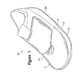
- Article of footwear 10 is depicted in Figures 1 and 2 as including an upper 11 and a sole structure 12.
- Upper 11 may incorporate a plurality material elements (e.g., textiles, foam, and leather) that are stitched or adhesively bonded together to form an interior void for securely and comfortably receiving a foot.
- the material elements may be selected and located with respect to upper 11 in order to selectively impart properties of durability, air-permeability, wear-resistance, flexibility, and comfort, for example.
- upper 11 may include a lace that is utilized in a conventional manner to modify the dimensions of the interior void, thereby securing the foot within the interior void and facilitating entry and removal of the foot from the interior void.
- the lace may extend through apertures in upper 11, and a tongue portion of upper 11 may extend between the interior void and the lace.
- Footwear 10 may also incorporate a lace cover that provides protection to the laces during athletic activities. Accordingly, upper 11 may have a substantially conventional configuration within the scope of the present invention.
- Sole structure 12 is secured to a lower area of upper 11.
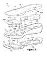
- the primary elements of sole structure 12 include a cover member 20, a frame member 30, three inserts 40a-40c, and an outsole 50.
- cover member 20, frame member 30, and inserts 40a-40c form a midsole portion of footwear 10 that may impart stability, attenuate ground reaction forces, and absorb shock, for example.
- Outsole 50 is secured to a lower surface of the midsole portion (i.e., frame member 30 and inserts 40a-40c) in order to impart wear-resistance and traction.
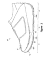
- sole structure 12 includes a lateral side 13, a medial side 14, a heel region 15, a midfoot region 16, and a forefoot region 17. Regions 15-17 are not intended to demarcate precise portions of footwear 10, but are intended to form areas of reference in the following discussion.
- Cover member 20 forms an upper portion of sole structure 12 that extends through at least a portion of the longitudinal length of footwear 10 (i.e., through regions 15-17) and between lateral side 13 and medial side 14.
- the primary surfaces of cover member 20 include an upper surface 21, a lower surface 22, and a side surface 23.
- cover member 20 may include three indentations 24a-24c that are formed in lower surface 22 for receiving upper portions of the various inserts 40a-40c.
- Upper surface 21 is positioned adjacent to upper 20 and may be secured to upper 20 in a conventional manner (e.g., with an adhesive). In order to conform with a shape of the foot received by upper 11 and provide support for the foot, upper surface 21 may exhibit a contoured configuration. More particularly, the contours of upper surface 21 may include a depression in heel region 15 for supporting the heel, and the contours of upper surface 21 may include a raised area on medial side 14 and in midfoot region 16 for supporting an arch area of the foot.
- Frame member 30 supports cover member 20 and also extends through at least a portion of the longitudinal length of footwear 10 and between lateral side 13 and medial side 14.
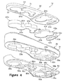
- Frame member 30 forms an exterior surface 31 and also defines three apertures 32a-32c.
- Exterior surface 31 is a generally vertical portion of frame member 30 that extends around frame member 30 and may also form the exterior surface of sole structure 12.
- Apertures 32a-32c respectively form sidewalls 33a-33c and extend entirely though frame member 30 to form areas for receiving the various inserts 40a-40c.
- Inserts 40a-40c are positioned within apertures 32a-32c and extend between cover member 20 and outsole 50.
- Insert 40a includes an upper surface 41a, a lower surface 42a, and a sidewall 43a.
- Upper surface 41 a extends into and may be joined or otherwise bonded with indentation 24a of cover member 20.
- lower surface 42a contacts and may be joined with outsole 50, as described in greater detail below.
- Sidewall 43a extends along and is substantially parallel to sidewall 33a of frame member 30. Rather than contact sidewall 33a, however, a space 44a is formed between sidewall 33a and sidewall 43a.
- the distance across space 44a (i.e., the distance between sidewall 33a and sidewall 43a) is depicted as being substantially constant around insert 40a, but may vary in some embodiments of the invention. In some embodiments of the invention, sidewall 43a may contact sidewall 33a.
- Inserts 40b-40c exhibit a configuration that is similar to insert 40a. Accordingly, inserts 40b-40c respectively include upper surfaces 41b-41c, lower surfaces 42b-42c, and sidewalls 43b-43c. As with insert 40a, upper surfaces 41b-41c respectively extend into and may be joined or otherwise bonded with indentations 24b-24c. Similarly, lower surfaces 42b-42c contact and may be joined with outsole 50. In addition, spaces 44b-44c are respectively formed between sidewalls 33b-33c and sidewalls 43b-43c. The distance across spaces 44b-44c is also depicted as being substantially constant, but may vary in some embodiments of the invention.
- inserts 40a-40c respectively correspond with the shapes of the various inserts 40a-40c. In general, however, the dimensions of apertures 32a-32c are greater than the dimensions of inserts 40a-40c, thereby forming spaces 44a-44c between the respective components.
- Inserts 40a-40c have the shapes of overlapping or tangentially-connected rounded regions. More particularly, insert 40a has the shape of five overlapping or tangentially-connected circular regions, insert 40b has three circular regions, and insert 40c has two circular regions. In further embodiments of the invention, inserts 40a-40c may have a variety of other shapes and are not limited to overlapping configurations.
- circular regions may be replaced with triangular, square, oval, hexagonal, or pentagonal regions for example, or other non-geometrically-shaped regions.
- the number of regions in each of inserts 40a-40c and the number of inserts may vary considerably. Accordingly, the specific configuration of the various inserts 40a-40c may vary significantly within the scope of the present invention.
- Insert 40a has the shape of five overlapping or tangentially-connected circular regions that are arranged to extend through heel region 15 and into midfoot region 16.
- a first of the circular regions of insert 40a which is also the largest in diameter, is located within heel region 15 and is positioned to be equidistant from lateral side 13 and medial side 14.
- the first of the circular regions is, therefore, positioned to correspond with a location of a calcaneus bone of the foot and operates to provide support to the calcaneus bone.
- a second of the circular regions is closer to medial side 14 than lateral side 13.
- a third of the circular regions is closer to lateral side 13 than medial side 14.
- a fourth and fifth of the circular regions are positioned in midfoot region 16 and correspond in location with an arch area of the foot.
- the pattern for the various regions of insert 40a described above generally correspond with and complement the manner in which the foot rolls during the running motion.
- the motion of the foot during running proceeds as follows: Initially, the heel strikes the ground, followed by the ball of the foot. As the heel leaves the ground, the foot rolls forward so that the toes make contact, and finally the entire foot leaves the ground to begin another cycle. During the time that the foot is in contact with the ground, the foot typically rolls from the outside (i.e., lateral side 13) to the inside (i.e., medial side 14), a process called pronation. That is, normally, the outside of the heel strikes first and the toes on the inside of the foot leave the ground last. Accordingly, the various regions of insert 40a are positioned at areas of relatively high foot pressure during the running cycle.
- Insert 40b has the shape of three overlapping or tangentially-connected circular regions that are arranged in a triangular pattern. The position of insert 40b generally corresponds with the transition area between midfoot region 16 and forefoot region 17. Insert 40b is located, therefore, to correspond with the position of the joints between the metatarsals and the proximal phalanges of the foot. One of the circular regions of insert 40b has a greater diameter than the remaining circular regions and is positioned to correspond in location with the joint between the first metatarsal and the first proximal phalanx. Insert 40c has the shape of two overlapping or tangentially-connected circular regions that are arranged linearly. Insert 40c is positioned within forefoot region 17 and corresponds in location with forward areas of the foot (e.g., the distal phalanges of the second through fourth digits).
- the thickness of sole structure 12 decreases between heel region 15 and forefoot region 17.
- Insert 40a is positioned in heel region 15 and exhibits a greater thickness than either of inserts 40b and 40c.
- insert 40b is positioned in midfoot region 16 and exhibits a greater thickness than insert 40c.
- the various thicknesses of inserts 40a-40c may be selected, therefore, to conform with the general decrease in thickness of sole structure 12 between heel region 15 and forefoot region 17.
- Cover member 20, frame member 30, and inserts 40a-40c are depicted in the figures as being separate elements of sole structure 12. In some embodiments of the invention, however, cover member 20 and frame member 30 may be formed of unitary (i.e., one piece) construction. Cover member 20 and one or more of inserts 40a-40c may also be formed of unitary construction. Suitable materials for cover member 20, frame member 30, and inserts 40a-40c include any of the materials conventionally utilized in footwear midsoles, including polyurethane and ethylvinylacetate foam, for example. The density of the foams that are utilized for cover member 20, frame member 30, and inserts 40a-40c may also vary.
- cover member 20 and frame member 30 may be formed of a foam with a greater density than the foam forming inserts 40a-40c.
- inserts 40a-40c may be formed from foams with different densities, and each of the regions of inserts 40a-40c may be formed to exhibit different foam densities.
- the regions positioned adjacent to lateral side 13 may have a greater density than the regions positioned adjacent to medial side 14, thereby operating to limit pronation of the foot during running.
- inserts 40a-40c may be formed from various fluid-filled bladders, as disclosed in U.S. Patent Number 4,183,156 to Rudy , for example.
- Outsole 50 is positioned to form a ground-engaging surface of footwear 10 and extends under cover member 20, frame member 30, and inserts 40a-40c.
- Outsole 50 includes an upper surface 51 and an opposite lower surface 52.
- Upper surface 51 defines three ridges 53a-53c that respectively correspond in shape to inserts 40a-40c, and ridges 53a-53c respectively define three depressions 54a-54c in outsole 50.
- Insert 40a extends into depression 54a such that ridge 53a extends around a lower area of insert 40a.
- Ridge 53a is positioned between sidewall 33a and sidewall 43a. Ridge 53a is therefore, positioned within a lower area of space 44a.
- insert 40b-40c respectively extend into depressions 54b-54c such that ridges 53b-53c extend around lower areas of inserts 40b-40c. Ridges 53b-53c are also respectively positioned between sidewalls 33b-33c and sidewalls 43b-43c. Ridges 53b-53c are, therefore, positioned within lower areas of spaces 44b-44c.
- Outsole 50 also includes various protrusions 55a-55c that extend outward from lower surface 52. Protrusions 55a-55c correspond in location with depressions 54a-54c. Three grooves 56a-56c also extend around each of protrusions 55a-55c and correspond in location with ridges 53a-53c.
- Suitable materials for outsole 50 include any of the conventional materials utilized for footwear outsoles, such as carbon black rubber compound. Inserts 40a-40c are adhesively bonded to outsole 50, but may remain unbonded in some embodiments of the invention.
- sole structure 12 During ambulatory motions, such as walking and running, sole structure 12 is compressed between the foot and the ground. Protrusions 55a-55c extend below the level of other portions of sole structure 12 and initially contact the ground during the ambulatory activities.
- the configuration of ridges 53a-53c and grooves 56a-56c permit outsole 50 to displace vertically and operate, therefore, in a manner that is analogous to a speaker diaphragm.
- Inserts 40a-40c are bonded between cover member 20 and outsole 50, but are free from any bonding or other restrictions along sidewalls 33a-33c. This configuration allows for the independent vertical displacement of inserts 40a-40c with respect to each other and with respect to frame member 30.
- inserts 40a-40c provides zones of independent compressibility in sole structure 12.
- sole structure 12 is depicted in an uncompressed configuration.
- inserts 40a-40b are depicted as being compressed, and inserts 40a and 40b bow outward into spaces 44a-44b.
- the various inserts 40a-40c may, therefore, deflect independently.
- each of the regions of inserts 40a-40c may be formed to exhibit different foam densities.
- the regions positioned adjacent to lateral side 13 may have a greater density than the regions positioned adjacent to medial side 14, thereby operating to limit pronation of the foot during running.
- each of inserts 40a-40c may be formed from polymer foams with different densities. Some individuals may prefer, for example, that insert 40a be formed from a polymer foam that is more dense than the polymer foam of inserts 40b and 40c.
- sole structure 12 may be tuned to the preferences of particular individuals by merely modifying the properties of inserts 40a-40c.
- inserts 40a-40c may also be utilized to configure footwear 10 for different activities.
- one configuration of polymer foam densities may be suitable for basketball, whereas another configuration of polymer foam densities may be suitable for running.
- Two different articles of footwear may be made, therefore, with substantially similar soles, except for the materials selected for inserts 40a-40c. Accordingly, the configuration disclosed with respect to sole structure 12 provides significant design latitude for tailoring footwear 10 to a particular individual or a particular athletic activity.
- aperture 44 extends through insert 40a.
- aperture 44 extends entirely through insert 40a, but may also extend only partially through insert 40a.
- the sidewall of aperture 44 will deform in a manner that is analogous to sidewall 43a, for example.
- the manner in which insert 40a compresses during ambulatory motions is at least partially dependent upon the dimensions of aperture 44.
- aperture 44a may have a variety of dimensions and shapes within the scope of the present invention.
- a fluid-filled bladder 45 is located within aperture 44.
- Bladder 45 may have a configuration that corresponds with any of the conventional fluid-filled bladders discussed above in the Background of the Invention section. Although aperture 44 and bladder 45 are discussed above in relation to insert 40a, similar structures may be incorporated into any of inserts 40a-40c.
Abstract
Description
- The present invention relates to sole structures for articles of footwear. The invention concerns, more particularly, a sole structure for an article of footwear that includes compressible midsole inserts.
- A conventional article of athletic footwear includes two primary elements, an upper and a sole structure. The upper provides a covering for the foot that securely receives and positions the foot with respect to the sole structure. In addition, the upper may have a configuration that protects the foot and provides ventilation, thereby cooling the foot and removing perspiration. The sole structure is secured to a lower surface of the upper and is generally positioned between the foot and the ground. In addition to attenuating ground reaction forces and absorbing energy (i.e., imparting cushioning), the sole structure may provide traction and control foot motions, such as over pronation. Accordingly, the upper and the sole structure operate cooperatively to provide a comfortable structure that is suited for a wide variety of ambulatory activities, such as walking and running.
- The sole structure of athletic footwear generally exhibits a layered configuration that includes a comfort-enhancing insole, a resilient midsole formed from a polymer foam, and a ground-contacting outsole that provides both abrasion-resistance and traction. The midsole is the primary sole structure element that imparts cushioning and controls foot motions. Suitable polymer foam materials for the midsole include ethylvinylacetate or polyurethane that compress resiliently under an applied load to attenuate ground reaction forces and absorb energy. Conventional polymer foam materials are resiliently compressible, in part, due to the inclusion of a plurality of open or closed cells that define an inner volume substantially displaced by gas.
- The midsole may be formed from a unitary element of polymer foam that extends throughout the length and width of the footwear. With the exception of a thickness differential between the heel and forefoot areas of the footwear, such a midsole exhibits substantially uniform properties in each area of the sole structure. In order to vary the properties of midsole, some conventional midsoles incorporate dual-density polymer foams. More particularly, a lateral side of the midsole may be formed from a first foam material, and the medial side of the midsole may be formed from a second, less compressible foam material. Another means of varying the properties of the midsole involves the use of stability devices that resist pronation. Examples of stability devices include
U.S. Patent Numbers 4,255,877 to Bowerman ;4,288,929 to Norton et al. ;4,354,318 to Frederick et al. ;4,364,188 to Turner et al. ;4,364,189 to Bates ; and5,247,742 to Kilgore et al. - Another manner of varying the properties of the midsole involves the use of fluid-filled bladders.
U.S. Patent Number 4,183,156 to Rudy , discloses an inflatable insert formed of elastomeric materials. The insert includes a plurality of tubular chambers that extend substantially longitudinally throughout the length of the footwear. The chambers are in fluid communication with each other and jointly extend across the width of the footwear.U.S. Patent Number 4,219,945 to Rudy discloses an inflated insert encapsulated in a polymer foam material. The combination of the insert and the encapsulating polymer foam material functions as a midsole. Examples of additional fluid-filled bladders for footwear includeU.S. Patent Numbers 4,906,502 and5,083,361, both to Rudy andU.S. Patent Numbers 5,993,585 and6,119,371, both to Goodwin et al. - The present invention is an article of footwear incorporating an upper and a sole structure secured to the upper. The sole structure includes a midsole and an outsole. The midsole extends along at least a portion of a longitudinal length of the footwear, and the midsole defines an aperture with a first sidewall. The midsole includes an insert positioned within the aperture. The insert has a second sidewall, with at least a portion of the second sidewall being spaced from the first sidewall to define a space between the first sidewall and the second sidewall. The outsole is secured to the midsole, and the outsole defines a ridge that is positioned within a lower portion of the space and between the first sidewall and the second sidewall.
- In another aspect of the invention the midsole defines a first aperture and a separate second aperture, and the midsole includes a first insert and a second insert. The first insert is positioned within the first aperture, and at least a portion of a sidewall of the first aperture is spaced from a sidewall of the first insert. The first insert has a shape of at least three connected rounded regions. The second insert is positioned within the second aperture, and at least a portion of a sidewall of the second aperture is spaced from a sidewall of the second insert. The second insert has a shape of at least two connected rounded regions. The outsole is secured to the midsole, and the outsole defines a first ridge and a second ridge. The first ridge is positioned between the sidewall of the first aperture and the sidewall of the first insert, and the second ridge is positioned between the sidewall of the second aperture and the sidewall of the second insert.
- In yet another aspect of the invention the midsole is formed of a polymer foam material that defines an aperture. The midsole includes an insert that is positioned within the aperture, and the insert being spaced from a sidewall of the aperture. The insert may have a shape of at least two connected rounded regions. The outsole is secured to the midsole, and the outsole defines a ridge that is positioned between the sidewall of the aperture and the insert.
- The advantages and features of novelty characterizing the present invention are pointed out with particularity in the appended claims. To gain an improved understanding of the advantages and features of novelty, however, reference may be made to the following descriptive matter and accompanying drawings that describe and illustrate various embodiments and concepts related to the invention.
- The foregoing Summary of the Invention, as well as the following Detailed Description of the Invention, will be better understood when read in conjunction with the accompanying drawings.
-
Figure 1 is a perspective view of an article of footwear having a sole structure in accordance with the present invention. -
Figure 2 is a side elevational view of the article of footwear. -
Figure 3 is a first exploded perspective view of the sole structure. -
Figure 4 is a second exploded perspective view of the sole structure. -
Figure 5A is a cross-sectional view of the sole structure in an uncompressed configuration, as defined along section line 5-5 inFigure 7 . -
Figure 5B is a cross-sectional view of the sole structure in a compressed configuration, as defined along section line 5-5 inFigure 7 . -
Figure 6A is a cross-sectional view of the sole structure in an uncompressed configuration, as defined along section line 6-6 inFigure 7 . -
Figure 6B is a cross-sectional view of the sole structure in a compressed configuration, as defined along section line 6-6 inFigure 7 . -
Figure 7 is a top plan view of a portion of the sole structure. -
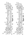
Figure 8 is a cross-sectional view of the sole structure according to another embodiment of the invention, the cross-sectional view corresponding withFigure 6A . -
Figure 9 is a cross-sectional view of the sole structure according to yet another embodiment of the invention, the cross-sectional view corresponding withFigure 6A . - The following discussion and accompanying figures disclose an article of
footwear 10 in accordance with the present invention. Concepts related to article offootwear 10 are disclosed with reference to footwear having a configuration that is suitable for the sport of basketball. The invention is not solely limited to footwear designed for basketball, however, and may be applied to a wide range of athletic footwear styles that include running shoes, walking shoes, cross-training shoes, tennis shoes, soccer shoes, and football shoes, for example. In addition to athletic footwear, concepts related to the invention may be applied to non-athletic footwear (e.g., dress shoes and work boots) or footwear serving a medical or rehabilitative purpose. Accordingly, one skilled in the relevant art will appreciate that the concepts disclosed herein apply to a wide variety of footwear styles, in addition to the specific style discussed in the following material and depicted in the accompanying figures. - Article of
footwear 10 is depicted inFigures 1 and2 as including an upper 11 and asole structure 12.Upper 11 may incorporate a plurality material elements (e.g., textiles, foam, and leather) that are stitched or adhesively bonded together to form an interior void for securely and comfortably receiving a foot. The material elements may be selected and located with respect to upper 11 in order to selectively impart properties of durability, air-permeability, wear-resistance, flexibility, and comfort, for example. In addition, upper 11 may include a lace that is utilized in a conventional manner to modify the dimensions of the interior void, thereby securing the foot within the interior void and facilitating entry and removal of the foot from the interior void. The lace may extend through apertures in upper 11, and a tongue portion of upper 11 may extend between the interior void and the lace.Footwear 10 may also incorporate a lace cover that provides protection to the laces during athletic activities. Accordingly, upper 11 may have a substantially conventional configuration within the scope of the present invention. -
Sole structure 12, as depicted inFigures 3-7 , is secured to a lower area of upper 11. The primary elements ofsole structure 12 include acover member 20, aframe member 30, threeinserts 40a-40c, and anoutsole 50. Collectively,cover member 20,frame member 30, and inserts 40a-40c form a midsole portion offootwear 10 that may impart stability, attenuate ground reaction forces, and absorb shock, for example.Outsole 50 is secured to a lower surface of the midsole portion (i.e.,frame member 30 and inserts 40a-40c) in order to impart wear-resistance and traction. For purposes of reference in the following discussion,sole structure 12 includes alateral side 13, amedial side 14, aheel region 15, amidfoot region 16, and aforefoot region 17. Regions 15-17 are not intended to demarcate precise portions offootwear 10, but are intended to form areas of reference in the following discussion. -
Cover member 20 forms an upper portion ofsole structure 12 that extends through at least a portion of the longitudinal length of footwear 10 (i.e., through regions 15-17) and betweenlateral side 13 andmedial side 14. The primary surfaces ofcover member 20 include anupper surface 21, alower surface 22, and aside surface 23. In addition, to surfaces 21-23,cover member 20 may include threeindentations 24a-24c that are formed inlower surface 22 for receiving upper portions of thevarious inserts 40a-40c.Upper surface 21 is positioned adjacent to upper 20 and may be secured to upper 20 in a conventional manner (e.g., with an adhesive). In order to conform with a shape of the foot received by upper 11 and provide support for the foot,upper surface 21 may exhibit a contoured configuration. More particularly, the contours ofupper surface 21 may include a depression inheel region 15 for supporting the heel, and the contours ofupper surface 21 may include a raised area onmedial side 14 and inmidfoot region 16 for supporting an arch area of the foot. -
Frame member 30 supports covermember 20 and also extends through at least a portion of the longitudinal length offootwear 10 and betweenlateral side 13 andmedial side 14.Frame member 30 forms anexterior surface 31 and also defines threeapertures 32a-32c.Exterior surface 31 is a generally vertical portion offrame member 30 that extends aroundframe member 30 and may also form the exterior surface ofsole structure 12.Apertures 32a-32c respectively form sidewalls 33a-33c and extend entirely thoughframe member 30 to form areas for receiving thevarious inserts 40a-40c. -
Inserts 40a-40c are positioned withinapertures 32a-32c and extend betweencover member 20 andoutsole 50.Insert 40a includes anupper surface 41a, alower surface 42a, and asidewall 43a. Upper surface 41 a extends into and may be joined or otherwise bonded withindentation 24a ofcover member 20. Similarly,lower surface 42a contacts and may be joined withoutsole 50, as described in greater detail below.Sidewall 43a extends along and is substantially parallel tosidewall 33a offrame member 30. Rather thancontact sidewall 33a, however, aspace 44a is formed betweensidewall 33a andsidewall 43a. The distance acrossspace 44a (i.e., the distance betweensidewall 33a andsidewall 43a) is depicted as being substantially constant aroundinsert 40a, but may vary in some embodiments of the invention. In some embodiments of the invention,sidewall 43a may contactsidewall 33a. -
Inserts 40b-40c exhibit a configuration that is similar to insert 40a. Accordingly, inserts 40b-40c respectively includeupper surfaces 41b-41c,lower surfaces 42b-42c, and sidewalls 43b-43c. As withinsert 40a,upper surfaces 41b-41c respectively extend into and may be joined or otherwise bonded withindentations 24b-24c. Similarly,lower surfaces 42b-42c contact and may be joined withoutsole 50. In addition,spaces 44b-44c are respectively formed betweensidewalls 33b-33c andsidewalls 43b-43c. The distance acrossspaces 44b-44c is also depicted as being substantially constant, but may vary in some embodiments of the invention. - The shapes of the
various apertures 32a-32c respectively correspond with the shapes of thevarious inserts 40a-40c. In general, however, the dimensions ofapertures 32a-32c are greater than the dimensions ofinserts 40a-40c, thereby formingspaces 44a-44c between the respective components.Inserts 40a-40c have the shapes of overlapping or tangentially-connected rounded regions. More particularly,insert 40a has the shape of five overlapping or tangentially-connected circular regions,insert 40b has three circular regions, andinsert 40c has two circular regions. In further embodiments of the invention, inserts 40a-40c may have a variety of other shapes and are not limited to overlapping configurations. In addition, the circular regions may be replaced with triangular, square, oval, hexagonal, or pentagonal regions for example, or other non-geometrically-shaped regions. Furthermore, the number of regions in each ofinserts 40a-40c and the number of inserts may vary considerably. Accordingly, the specific configuration of thevarious inserts 40a-40c may vary significantly within the scope of the present invention. -
Insert 40a, as discussed above, has the shape of five overlapping or tangentially-connected circular regions that are arranged to extend throughheel region 15 and intomidfoot region 16. A first of the circular regions ofinsert 40a, which is also the largest in diameter, is located withinheel region 15 and is positioned to be equidistant fromlateral side 13 andmedial side 14. The first of the circular regions is, therefore, positioned to correspond with a location of a calcaneus bone of the foot and operates to provide support to the calcaneus bone. A second of the circular regions is closer tomedial side 14 thanlateral side 13. Similarly, a third of the circular regions is closer tolateral side 13 thanmedial side 14. A fourth and fifth of the circular regions are positioned inmidfoot region 16 and correspond in location with an arch area of the foot. - The pattern for the various regions of
insert 40a described above generally correspond with and complement the manner in which the foot rolls during the running motion. In general, the motion of the foot during running proceeds as follows: Initially, the heel strikes the ground, followed by the ball of the foot. As the heel leaves the ground, the foot rolls forward so that the toes make contact, and finally the entire foot leaves the ground to begin another cycle. During the time that the foot is in contact with the ground, the foot typically rolls from the outside (i.e., lateral side 13) to the inside (i.e., medial side 14), a process called pronation. That is, normally, the outside of the heel strikes first and the toes on the inside of the foot leave the ground last. Accordingly, the various regions ofinsert 40a are positioned at areas of relatively high foot pressure during the running cycle. -
Insert 40b has the shape of three overlapping or tangentially-connected circular regions that are arranged in a triangular pattern. The position ofinsert 40b generally corresponds with the transition area betweenmidfoot region 16 andforefoot region 17.Insert 40b is located, therefore, to correspond with the position of the joints between the metatarsals and the proximal phalanges of the foot. One of the circular regions ofinsert 40b has a greater diameter than the remaining circular regions and is positioned to correspond in location with the joint between the first metatarsal and the first proximal phalanx.Insert 40c has the shape of two overlapping or tangentially-connected circular regions that are arranged linearly.Insert 40c is positioned withinforefoot region 17 and corresponds in location with forward areas of the foot (e.g., the distal phalanges of the second through fourth digits). - The thickness of
sole structure 12 decreases betweenheel region 15 andforefoot region 17.Insert 40a is positioned inheel region 15 and exhibits a greater thickness than either ofinserts insert 40b is positioned inmidfoot region 16 and exhibits a greater thickness thaninsert 40c. The various thicknesses ofinserts 40a-40c may be selected, therefore, to conform with the general decrease in thickness ofsole structure 12 betweenheel region 15 andforefoot region 17. -
Cover member 20,frame member 30, and inserts 40a-40c are depicted in the figures as being separate elements ofsole structure 12. In some embodiments of the invention, however,cover member 20 andframe member 30 may be formed of unitary (i.e., one piece) construction.Cover member 20 and one or more ofinserts 40a-40c may also be formed of unitary construction. Suitable materials forcover member 20,frame member 30, and inserts 40a-40c include any of the materials conventionally utilized in footwear midsoles, including polyurethane and ethylvinylacetate foam, for example. The density of the foams that are utilized forcover member 20,frame member 30, and inserts 40a-40c may also vary. For example,cover member 20 andframe member 30 may be formed of a foam with a greater density than thefoam forming inserts 40a-40c. Each ofinserts 40a-40c may be formed from foams with different densities, and each of the regions ofinserts 40a-40c may be formed to exhibit different foam densities. For example, the regions positioned adjacent tolateral side 13 may have a greater density than the regions positioned adjacent tomedial side 14, thereby operating to limit pronation of the foot during running. In addition to polymer foams, inserts 40a-40c may be formed from various fluid-filled bladders, as disclosed inU.S. Patent Number 4,183,156 to Rudy , for example. -
Outsole 50 is positioned to form a ground-engaging surface offootwear 10 and extends undercover member 20,frame member 30, and inserts 40a-40c.Outsole 50 includes anupper surface 51 and an oppositelower surface 52.Upper surface 51 defines threeridges 53a-53c that respectively correspond in shape toinserts 40a-40c, andridges 53a-53c respectively define threedepressions 54a-54c inoutsole 50.Insert 40a extends intodepression 54a such thatridge 53a extends around a lower area ofinsert 40a.Ridge 53a is positioned betweensidewall 33a andsidewall 43a.Ridge 53a is therefore, positioned within a lower area ofspace 44a. Similarly, insert 40b-40c respectively extend intodepressions 54b-54c such thatridges 53b-53c extend around lower areas ofinserts 40b-40c.Ridges 53b-53c are also respectively positioned betweensidewalls 33b-33c andsidewalls 43b-43c.Ridges 53b-53c are, therefore, positioned within lower areas ofspaces 44b-44c.Outsole 50 also includesvarious protrusions 55a-55c that extend outward fromlower surface 52.Protrusions 55a-55c correspond in location withdepressions 54a-54c. Threegrooves 56a-56c also extend around each ofprotrusions 55a-55c and correspond in location withridges 53a-53c.Grooves 56a-56c extend, therefore, intoridges 53a-53c, as depicted in the cross-sections ofFigures 5A-6B . Suitable materials foroutsole 50 include any of the conventional materials utilized for footwear outsoles, such as carbon black rubber compound.Inserts 40a-40c are adhesively bonded tooutsole 50, but may remain unbonded in some embodiments of the invention. - The operation of
sole structure 12 will now be discussed. During ambulatory motions, such as walking and running,sole structure 12 is compressed between the foot and the ground.Protrusions 55a-55c extend below the level of other portions ofsole structure 12 and initially contact the ground during the ambulatory activities. The configuration ofridges 53a-53c andgrooves 56a-56c permit outsole 50 to displace vertically and operate, therefore, in a manner that is analogous to a speaker diaphragm.Inserts 40a-40c are bonded betweencover member 20 andoutsole 50, but are free from any bonding or other restrictions alongsidewalls 33a-33c. This configuration allows for the independent vertical displacement ofinserts 40a-40c with respect to each other and with respect to framemember 30. That is, the configuration ofinserts 40a-40c provides zones of independent compressibility insole structure 12. Referring toFigures 5A and6A ,sole structure 12 is depicted in an uncompressed configuration. InFigures 5B and6B , however, inserts 40a-40b are depicted as being compressed, and inserts 40a and 40b bow outward intospaces 44a-44b. Thevarious inserts 40a-40c may, therefore, deflect independently. - The configuration of
sole structure 12 discussed above provides variability in the properties offootwear 10. As discussed above, each of the regions ofinserts 40a-40c may be formed to exhibit different foam densities. For example, the regions positioned adjacent tolateral side 13 may have a greater density than the regions positioned adjacent tomedial side 14, thereby operating to limit pronation of the foot during running. As a further alternative, each ofinserts 40a-40c may be formed from polymer foams with different densities. Some individuals may prefer, for example, thatinsert 40a be formed from a polymer foam that is more dense than the polymer foam ofinserts manufacturing footwear 10, therefore,sole structure 12 may be tuned to the preferences of particular individuals by merely modifying the properties ofinserts 40a-40c. Differences in the properties ofinserts 40a-40c may also be utilized to configurefootwear 10 for different activities. For example, one configuration of polymer foam densities may be suitable for basketball, whereas another configuration of polymer foam densities may be suitable for running. Two different articles of footwear may be made, therefore, with substantially similar soles, except for the materials selected forinserts 40a-40c. Accordingly, the configuration disclosed with respect tosole structure 12 provides significant design latitude for tailoringfootwear 10 to a particular individual or a particular athletic activity. - With reference to
Figure 8 , another embodiment of the invention is depicted, wherein an aperture 44 extends throughinsert 40a. As depicted, aperture 44 extends entirely throughinsert 40a, but may also extend only partially throughinsert 40a. Wheninsert 40a is compressed, the sidewall of aperture 44 will deform in a manner that is analogous tosidewall 43a, for example. The manner in which insert 40a compresses during ambulatory motions is at least partially dependent upon the dimensions of aperture 44. Accordingly,aperture 44a may have a variety of dimensions and shapes within the scope of the present invention. Referring toFigure 9 , yet another embodiment of the invention is depicted, wherein a fluid-filledbladder 45 is located within aperture 44.Bladder 45 may have a configuration that corresponds with any of the conventional fluid-filled bladders discussed above in the Background of the Invention section. Although aperture 44 andbladder 45 are discussed above in relation to insert 40a, similar structures may be incorporated into any ofinserts 40a-40c. - The present invention is disclosed above and in the accompanying drawings with reference to a variety of embodiments. The purpose served by the disclosure, however, is to provide an example of the various features and concepts related to the invention, not to limit the scope of the invention. One skilled in the relevant art will recognize that numerous variations and modifications may be made to the embodiments described above without departing from the scope of the present invention, as defined by the appended claims.
-
- 1. An article of footwear incorporating an upper and a sole structure secured to the upper, the sole structure comprising:
- a midsole extending along at least a portion of a longitudinal length of the footwear, the midsole defining an aperture with a first sidewall, the midsole including an insert positioned within the aperture, the insert having a second sidewall, at least a portion of the second sidewall being spaced from the first sidewall to define a space between the first sidewall and the second sidewall; and
- an outsole secured to the midsole, the outsole defining a ridge that is positioned within a lower portion of the space and between the first sidewall and the second sidewall.
- 2. The article of footwear recited in clause 1, wherein a shape of the insert corresponds with a shape of the aperture.
- 3. The article of footwear recited in clause 2, wherein the shape of the insert includes at least two overlapping rounded regions.
- 4. The article of footwear recited in clause 2, wherein the shape of the insert includes at least two circular regions.
- 5. The article of footwear recited in clause 1, wherein a distance between the first sidewall and the second sidewall is substantially constant around the insert.
- 6. The article of footwear recited in clause 1, wherein the midsole includes a frame member and a cover member, the frame member defining the aperture and the cover member extending over the aperture and the insert.
- 7. The article of footwear recited in clause 6, wherein the cover member is secured to the upper.
- 8. The article of footwear recited in clause 6, wherein a lower surface of the cover member includes an indentation for receiving an upper surface of the insert.
- 9. The article of footwear recited in clause 1, wherein the first sidewall and the second sidewall exhibit a substantially vertical orientation.
- 10. The article of footwear recited in clause 1 , wherein the outsole defines a depression for receiving the insert.
- 11. The article of footwear recited in
clause 10, wherein the ridge extends around the depression. - 12. The article of footwear recited in
clause 10, wherein a lower surface of the outsole protrudes outward below the depression. - 13. The article of footwear recited in clause 1, wherein a distance across the space decreases when the sole structure is compressed.
- 14. The article of footwear recited in clause 1, wherein compressing the sole structure increases a diameter of the insert and decreases a distance across the space.
- 15. The article of footwear recited in clause 1, wherein the midsole element defines at least one additional aperture that is separate from the aperture, and the footwear includes an additional insert that is separate from the insert, the additional aperture receiving the additional insert.
- 16. The article of footwear recited in clause 1 , wherein the outsole defines a protrusion located opposite the ridge, the protrusion extending under the insert.
- 17. The article of footwear recited in
clause 16, wherein the protrusion exhibits a shape that corresponds with a shape of the insert. - 18. The article of footwear recited in clause 1, wherein an insert aperture extends at least partially through the insert.
- 19. The article of footwear recited in clause 18, wherein a fluid-filled bladder is positioned within the insert aperture.
- 20. An article of footwear incorporating an upper and a sole structure secured to the upper, the sole structure comprising:
- a frame member extending along at least a portion of a longitudinal length of the footwear, the frame member defining an aperture with a first sidewall;
- an insert positioned within the aperture, the insert including an upper surface, a lower surface, and a second sidewall extending between the upper surface and the lower surface, at least a portion of the second sidewall being spaced from the first sidewall to define a space between the first sidewall and the second sidewall;
- a cover member extending over the aperture, a lower surface of the cover member defining an indentation that receives the upper surface of the insert; and
- an outsole extending under the aperture, the outsole defining a ridge that is positioned within a lower portion of the space and between the first sidewall and the second sidewall, and the outsole defining a depression for receiving the lower surface of the insert, the ridge extending at least partially around the depression.
- 21. The article of footwear recited in
clause 20, wherein a distance between the first sidewall and the second sidewall is substantially constant around the insert. - 22. The article of footwear recited in
clause 20, wherein the midsole element and the insert are formed from polymer foam materials, and a distance across the space decreases when the sole structure is compressed. - 23. The article of footwear recited in
clause 20, wherein compressing the sole structure increases a diameter of the insert and decreases a distance across the space. - 24. The article of footwear recited in
clause 20, wherein the cover member is secured to the upper. - 25. The article of footwear recited in
clause 20, wherein the first sidewall and the second sidewall exhibit a substantially vertical orientation. - 26. The article of footwear recited in
clause 20, wherein the frame member defines at least one additional aperture that is separate from the aperture, and the footwear includes an additional insert that is separate from the insert, the additional aperture receiving the additional insert. - 27. The article of footwear recited in
clause 20, wherein the outsole defines a protrusion located opposite the ridge, the protrusion extending under the insert. - 28. The article of footwear recited in clause 27, wherein the protrusion exhibits a shape that corresponds with a shape of the insert.
- 29. The article of footwear recited in
clause 20, wherein a shape of the insert corresponds with a shape of the aperture. - 30. The article of footwear recited in clause 29, wherein the shape of the insert includes at least two overlapping rounded regions.
- 31. The article of footwear recited in clause 29, wherein the shape of the insert includes at least two overlapping circular regions.
- 32. The article of footwear recited in
clause 20, wherein an insert aperture extends at least partially through the insert. - 33. The article of footwear recited in clause 32, wherein a fluid-filled bladder is positioned within the insert aperture.
- 34. An article of footwear incorporating an upper and a sole structure secured to the upper, the sole structure comprising:
- a midsole extending along at least a portion of a longitudinal length of the footwear and having a lateral side and a medial side, the midsole defining a first aperture and a separate second aperture, and the midsole including:
- a first insert positioned within the first aperture, at least a portion of a sidewall of the first aperture being spaced from a sidewall of the first insert, the first insert having a shape of at least three connected rounded regions; and
- a second insert positioned within the second aperture, at least a portion of a sidewall of the second aperture being spaced from a sidewall of the second insert, the second insert having a shape of at least two connected rounded regions; and
- an outsole secured to the midsole, the outsole defining a first ridge and a second ridge, the first ridge being positioned between the sidewall of the first aperture and the sidewall of the first insert, and the second ridge being positioned between the sidewall of the second aperture and the sidewall of the second insert.
- a midsole extending along at least a portion of a longitudinal length of the footwear and having a lateral side and a medial side, the midsole defining a first aperture and a separate second aperture, and the midsole including:
- 35. The article of footwear recited in clause 34, wherein a distance between the first sidewall of the first insert and the sidewall of the first aperture is substantially constant around the first insert.
- 36. The article of footwear recited in clause 34, wherein the midsole includes a frame member and a cover member, the frame member defining the first aperture and the second aperture, and the cover member extending over the first aperture and the second aperture.
- 37. The article of footwear recited in clause 36, wherein a lower surface of the cover member includes a first indentation for receiving an upper surface of the first insert, and the cover member includes a second indentation for receiving an upper surface of the second insert.
- 38. The article of footwear recited in clause 36, wherein the frame member, the first insert, and the second insert are formed from polymer foam materials.
- 39. The article of footwear recited in clause 34, wherein a distance between the sidewall of the first aperture and the sidewall of the first insert decreases when the sole structure is compressed.
- 40. The article of footwear recited in clause 39, wherein a distance between the sidewall of the second aperture and the sidewall of the second insert decreases when the sole structure is compressed.
- 41. The article of footwear recited in clause 34, wherein the outsole defines a first depression for receiving the first insert, and the outsole defines a second depression for receiving the second insert.
- 42. The article of footwear recited in clause 34, wherein a lower surface of the outsole includes a first protrusion and a second protrusion, the first protrusion having the shape of the first insert, and the second protrusion having the shape of the second insert.
- 43. The article of footwear recited in clause 34, wherein the first insert is positioned in a heel region of the footwear and exhibits a first thickness, and the second insert is positioned forward of the first insert and exhibits a second thickness, the first thickness being greater than the second thickness.
- 44. The article of footwear recited in clause 34, wherein an insert aperture extends at least partially through at least one of the first insert and the second insert.
- 45. The article of footwear recited in clause 44, wherein a fluid-filled bladder is positioned within the insert aperture.
- 46. An article of footwear incorporating an upper and a sole structure secured to the upper, the sole structure comprising:
- a midsole extending along at least a portion of a longitudinal length of the footwear and having a lateral side and a medial side, the midsole defining a first aperture and a separate second aperture, and the midsole including:
- a first insert positioned within the first aperture, the first insert having a shape of at least three connected rounded regions, a center of a first of the rounded regions being substantially equidistant from the lateral side and the medial side, a center of a second of the rounded regions being positioned closer the lateral side than the medial side, and a center of a third of the rounded regions being positioned closer the medial side than the lateral side, and
- a second insert positioned within the second aperture, the second insert having a shape of at least two connected rounded regions that are positioned in a medial-to-lateral direction with respect to each other; and an outsole secured to the midsole.
- a midsole extending along at least a portion of a longitudinal length of the footwear and having a lateral side and a medial side, the midsole defining a first aperture and a separate second aperture, and the midsole including:
- 47. The article of footwear recited in clause 46, wherein at least a portion of a sidewall of the first aperture is spaced from a sidewall of the first insert.
- 48. The article of footwear recited in clause 47, wherein at least a portion of a sidewall of the second aperture is spaced from a sidewall of the second insert.
- 49. The article of footwear recited in clause 46, wherein the outsole defines a first ridge and a second ridge, the first ridge being positioned between the first aperture and the first insert, and the second ridge being positioned between the second aperture and the second insert.
- 50. The article of footwear recited in clause 46, wherein a distance between the first insert and a sidewall of the first aperture is substantially constant around the first insert.
- 51. The article of footwear recited in clause 46, wherein the midsole includes a frame member and a cover member, the frame member defining the first aperture and the second aperture, and the cover member extending over the first aperture and the second aperture.
- 52. The article of footwear recited in
clause 51, wherein a lower surface of the cover member includes a first indentation for receiving an upper surface of the first insert, and the cover member includes a second indentation for receiving an upper surface of the second insert. - 53. The article of footwear recited in clause 46, wherein a lower surface of the outsole includes a first protrusion and a second protrusion, the first protrusion having the shape of the first insert, and the second protrusion having the shape of the second insert.
- 54. The article of footwear recited in clause 46, wherein the first insert is positioned in a heel region of the footwear and exhibits a first thickness, and the second insert is positioned forward of the first insert and exhibits a second thickness, the first thickness being greater than the second thickness.
- 55. The article of footwear recited in clause 46, wherein the midsole includes a third insert positioned within a third aperture, the third insert having a shape of at least two connected rounded regions that are positioned in the medial-to-lateral direction with respect to each other.
- 56. An article of footwear incorporating an upper and a sole structure secured to the upper, the sole structure comprising:
- a midsole formed of a polymer foam material that defines an aperture, the midsole including an insert that is positioned within the aperture, the insert being spaced from a sidewall of the aperture, and the insert having a shape of at least two connected rounded regions; and
- an outsole secured to the midsole, the outsole defining a ridge that is positioned between the sidewall of the aperture and the insert.
- 57. The article of footwear recited in clause 56, wherein the rounded regions are circular.
- 58. The article of footwear recited in clause 56, wherein a distance between the sidewall of the aperture and the insert is substantially constant around the insert.
- 59. The article of footwear recited in clause 56, wherein the outsole defines a depression for receiving the insert.
- 60. The article of footwear recited in clause 59, wherein the ridge extends around the depression.
- 61. The article of footwear recited in clause 59, wherein a lower surface of the outsole protrudes outward below the depression.
- 62. The article of footwear recited in clause 56, wherein the outsole defines a protrusion located opposite the ridge, the protrusion extending under the insert.
- 63. The article of footwear recited in clause 62, wherein the protrusion exhibits a shape that corresponds with the shape of the insert.
Claims (15)
- An article of footwear incorporating an upper and a sole structure secured to the upper, the sole structure comprising:a midsole extending along at least a portion of a longitudinal length of the footwear and having a lateral side and a medial side, the midsole defining a first aperture and a separate second aperture, and the midsole including:a first insert positioned within the first aperture, the first insert having a shape of at least three connected rounded regions, a center of a first of the rounded regions being substantially equidistant from the lateral side and the medial side, a center of a second of the rounded regions being positioned closer to the medial side than the lateral side, and a center of a third of the rounded regions being positioned closer to the lateral side than the medial side, anda second insert positioned within the second aperture, the second insert having a shape of at least two connected rounded regions that are positioned in a medial-to-lateral direction with respect to each other; andan outsole secured to the midsole.
- The article of footwear recited in claim 1, wherein at least a portion of a sidewall of the first aperture is spaced from a sidewall of the first insert.
- The article of footwear recited in claim 1 or claim 2, wherein at least a portion of a sidewall of the second aperture is spaced from a sidewall of the second insert.
- The article of footwear recited in claim 1, wherein the outsole defines a first ridge and a second ridge, the first ridge being positioned between the first aperture and the first insert, and the second ridge being positioned between the second aperture and the second insert.
- The article of footwear recited in claim 1, wherein the midsole includes a frame member and a cover member, the frame member defining the first aperture and the second aperture, and the cover member extending over the first aperture and the second aperture.
- The article of footwear recited in claim 5, wherein a lower surface of the cover member includes a first indentation for receiving an upper surface of the first insert, and the cover member includes a second indentation for receiving an upper surface of the second insert.
- The article of footwear recited in claim 1 or claim 6, wherein a lower surface of the outsole includes a first protrusion and a second protrusion, the first protrusion having the shape of the first insert, and the second protrusion having the shape of the second insert.
- The article of footwear recited in claim 1, wherein the midsole includes a third insert positioned within a third aperture, the third insert having a shape of at least two connected rounded regions that are positioned in the medial-to-lateral direction with respect to each other.
- The article of footwear recited in claim 1, wherein the at least three connected rounded regions of the first insert include a first circular region, a second circular region, and a third circular region, and wherein the first insert further includes a fourth circular region and a fifth circular region positioned in a midfoot region of the sole structure.
- The article of footwear recited in claim 1, wherein the at least two connected rounded regions of the second insert are provided as part of three overlapping or tangentially-connected circular regions that are arranged in a triangular pattern and located to support a position of joints between metatarsals and proximal phalanges of a wearer's foot.
- The article of footwear recited in claim 1, wherein the first insert and the second insert are made from a polyurethane or ethylvinylacetate foam material.
- The article of footwear recited in claim 11, wherein the first insert is made from a foam material having a different density from a density of a foam material from which the second insert is made.
- The article of footwear recited in claim 1, wherein each of the first insert and the second insert is formed as a fluid-filled bladder.
- The article of footwear recited in claim 3, wherein the midsole includes a frame member and a cover member, the frame member defining the first aperture and the second aperture, wherein the cover member extends over the first aperture and the second aperture, and wherein the first insert and the second insert are bonded between the cover member and the outsole but are free from any bonding or other restrictions along the sidewall of the first insert and the sidewall of the second insert.
- The article of footwear recited in claim 1 or claim 14, wherein a lower surface of the outsole includes a first protrusion and a second protrusion located below the first insert and the second insert, respectively, and wherein the first and second protrusions extend below a level of other portions of the sole structure so as to initially contact ground during ambulatory activities.
Applications Claiming Priority (3)
| Application Number | Priority Date | Filing Date | Title |
|---|---|---|---|
| US10/862,055 US7200955B2 (en) | 2004-06-04 | 2004-06-04 | Article of footwear incorporating a sole structure with compressible inserts |
| EP10188762.8A EP2298109B1 (en) | 2004-06-04 | 2005-06-06 | Article of footwear incorporating a sole structure with compressible inserts |
| EP05762358A EP1753314B1 (en) | 2004-06-04 | 2005-06-06 | Article of footwear incorporating a sole structure with compressible inserts |
Related Parent Applications (3)
| Application Number | Title | Priority Date | Filing Date |
|---|---|---|---|
| EP10188762.8A Division EP2298109B1 (en) | 2004-06-04 | 2005-06-06 | Article of footwear incorporating a sole structure with compressible inserts |
| EP10188762.8A Division-Into EP2298109B1 (en) | 2004-06-04 | 2005-06-06 | Article of footwear incorporating a sole structure with compressible inserts |
| EP05762358A Division EP1753314B1 (en) | 2004-06-04 | 2005-06-06 | Article of footwear incorporating a sole structure with compressible inserts |
Publications (2)
| Publication Number | Publication Date |
|---|---|
| EP2937008A1 true EP2937008A1 (en) | 2015-10-28 |
| EP2937008B1 EP2937008B1 (en) | 2017-07-26 |
Family
ID=34982228
Family Applications (4)
| Application Number | Title | Priority Date | Filing Date |
|---|---|---|---|
| EP05762358A Active EP1753314B1 (en) | 2004-06-04 | 2005-06-06 | Article of footwear incorporating a sole structure with compressible inserts |
| EP15168410.7A Active EP2937008B1 (en) | 2004-06-04 | 2005-06-06 | Article of footwear incorporating a sole structure with compressible inserts |
| EP10188762.8A Active EP2298109B1 (en) | 2004-06-04 | 2005-06-06 | Article of footwear incorporating a sole structure with compressible inserts |
| EP10188766.9A Active EP2319343B1 (en) | 2004-06-04 | 2005-06-06 | Article of footwear incorporating a sole structure with compressible inserts |
Family Applications Before (1)
| Application Number | Title | Priority Date | Filing Date |
|---|---|---|---|
| EP05762358A Active EP1753314B1 (en) | 2004-06-04 | 2005-06-06 | Article of footwear incorporating a sole structure with compressible inserts |
Family Applications After (2)
| Application Number | Title | Priority Date | Filing Date |
|---|---|---|---|
| EP10188762.8A Active EP2298109B1 (en) | 2004-06-04 | 2005-06-06 | Article of footwear incorporating a sole structure with compressible inserts |
| EP10188766.9A Active EP2319343B1 (en) | 2004-06-04 | 2005-06-06 | Article of footwear incorporating a sole structure with compressible inserts |
Country Status (6)
| Country | Link |
|---|---|
| US (1) | US7200955B2 (en) |
| EP (4) | EP1753314B1 (en) |
| CN (2) | CN101589863B (en) |
| AT (1) | ATE494812T1 (en) |
| DE (1) | DE602005025869D1 (en) |
| WO (1) | WO2005117628A2 (en) |
Families Citing this family (172)
| Publication number | Priority date | Publication date | Assignee | Title |
|---|---|---|---|---|
| US6453577B1 (en) * | 1996-02-09 | 2002-09-24 | Reebok International Ltd. | Support and cushioning system for an article of footwear |
| US8256147B2 (en) | 2004-11-22 | 2012-09-04 | Frampton E. Eliis | Devices with internal flexibility sipes, including siped chambers for footwear |
| ITSV20040044A1 (en) * | 2004-12-07 | 2005-03-07 | Tn & Co Di Lucio Righetto | SOLE FOR FOOTWEAR AND FOOTWEAR WITH SUCH A SOLE |
| US20060218819A1 (en) * | 2005-03-30 | 2006-10-05 | Chi-Kung Wu | Double-density elastic insert element for an outsole |
| US7249425B2 (en) * | 2005-04-12 | 2007-07-31 | Swei Mu Wang | Shoe sole having soft cushioning device |
| US20070051018A1 (en) * | 2005-09-06 | 2007-03-08 | Columbia Insurance Company | Bladder with improved construction |
| US7685741B2 (en) * | 2005-12-05 | 2010-03-30 | The Grandoe Corporation | Multilayered footwear |
| DE102006015649B4 (en) * | 2006-04-04 | 2008-02-28 | Adidas International Marketing B.V. | shoe |
| US20080052960A1 (en) * | 2006-05-18 | 2008-03-06 | Manon Belley | Footwear construction |
| US9578922B2 (en) | 2006-11-06 | 2017-02-28 | Newton Running Company, Inc. | Sole construction for energy storage and rebound |
| US7882648B2 (en) * | 2007-06-21 | 2011-02-08 | Nike, Inc. | Footwear with laminated sole assembly |
| US8819961B1 (en) | 2007-06-29 | 2014-09-02 | Frampton E. Ellis | Sets of orthotic or other footwear inserts and/or soles with progressive corrections |
| US9795181B2 (en) * | 2007-10-23 | 2017-10-24 | Nike, Inc. | Articles and methods of manufacture of articles |
| US9788603B2 (en) | 2007-10-23 | 2017-10-17 | Nike, Inc. | Articles and methods of manufacture of articles |
| US9572402B2 (en) | 2007-10-23 | 2017-02-21 | Nike, Inc. | Articles and methods of manufacturing articles |
| US7895773B2 (en) * | 2007-11-06 | 2011-03-01 | Acushnet Company | Golf shoe |
| US8125796B2 (en) | 2007-11-21 | 2012-02-28 | Frampton E. Ellis | Devices with faraday cages and internal flexibility sipes |
| US8572867B2 (en) * | 2008-01-16 | 2013-11-05 | Nike, Inc. | Fluid-filled chamber with a reinforcing element |
| US8256145B2 (en) * | 2008-09-26 | 2012-09-04 | Nike, Inc. | Articles with retractable traction elements |
| US8079160B2 (en) | 2008-09-26 | 2011-12-20 | Nike, Inc. | Articles with retractable traction elements |
| USD597287S1 (en) | 2008-09-26 | 2009-08-04 | Reebok International Ltd. | Shoe sole |
| US8387281B2 (en) * | 2008-11-24 | 2013-03-05 | Srl, Inc. | Articles of footwear |
| EP2367453A4 (en) * | 2008-12-05 | 2013-09-04 | V Murali Krishna Pata | Perfect gait shoe |
| US8479413B2 (en) * | 2008-12-22 | 2013-07-09 | Msd Consumer Care, Inc. | Footwear insole for alleviating arthritis pain |
| US8196316B2 (en) * | 2009-01-26 | 2012-06-12 | Nike, Inc. | Article of footwear with two part midsole assembly |
| US8307569B2 (en) * | 2009-04-01 | 2012-11-13 | Reebok International Limited | Training footwear |
| US8424221B2 (en) * | 2009-04-01 | 2013-04-23 | Reebok International Limited | Training footwear |
| WO2010115004A1 (en) | 2009-04-02 | 2010-10-07 | Nike International, Ltd. | Traction elements |
| US8616892B2 (en) | 2009-04-02 | 2013-12-31 | Nike, Inc. | Training system for an article of footwear with a traction system |
| US20100275468A1 (en) * | 2009-04-29 | 2010-11-04 | Brown Shoe Company, Inc. | Air circulating footbed and method thereof |
| CN102405001A (en) * | 2009-04-30 | 2012-04-04 | 塞莱皇家股份公司 | Sport footwear having an outsole in composite material and process for obtaining the same |
| US8209885B2 (en) * | 2009-05-11 | 2012-07-03 | Brooks Sports, Inc. | Shoe assembly with non-linear viscous liquid |
| US8632342B2 (en) | 2009-05-28 | 2014-01-21 | Nike, Inc. | Training system for an article of footwear |
| US8573981B2 (en) | 2009-05-29 | 2013-11-05 | Nike, Inc. | Training system for an article of footwear with a ball control portion |
| US8127468B2 (en) * | 2009-06-10 | 2012-03-06 | Wolverine World Wide, Inc. | Footwear construction |
| US8166673B2 (en) * | 2009-07-10 | 2012-05-01 | Nike, Inc. | Air bladder footbed |
| NL2003367C2 (en) | 2009-08-20 | 2011-02-22 | Sara Lee De Nv | Cushioning element, footwear, insole, deformable filling, and envelope. |
| USD671304S1 (en) | 2009-09-28 | 2012-11-27 | Reebok International Limited | Shoe sole |
| US8453354B2 (en) | 2009-10-01 | 2013-06-04 | Nike, Inc. | Rigid cantilevered stud |
| US20110099845A1 (en) * | 2009-11-03 | 2011-05-05 | Miller Michael J | Customized footwear and methods for manufacturing |
| US8424225B2 (en) * | 2009-11-30 | 2013-04-23 | Nike, Inc. | Channeled sole for an article of footwear |
| US20110126422A1 (en) * | 2009-12-02 | 2011-06-02 | Brown Shoe Company, Inc. | Shoe sole with compressible protruding element |
| US20110179675A1 (en) * | 2010-01-14 | 2011-07-28 | Miller Michael J | Sport specific footwear insole |
| US20110192056A1 (en) * | 2010-02-05 | 2011-08-11 | Deckers Outdoor Corporation | Footwear including a self-adjusting midsole |
| US8533979B2 (en) | 2010-02-18 | 2013-09-17 | Nike, Inc. | Self-adjusting studs |
| US8322051B2 (en) | 2010-02-23 | 2012-12-04 | Nike, Inc. | Self-adjusting studs |
| EP2361521B1 (en) | 2010-02-25 | 2017-01-04 | Stonefly S.p.A. | Footwear with shock absorbing sole |
| US9021721B2 (en) * | 2010-05-07 | 2015-05-05 | Ariat International, Inc. | Footwear |
| US8782924B2 (en) | 2010-05-11 | 2014-07-22 | Nike, Inc. | Article of footwear having a sole structure with a framework-chamber arrangement |
| US9167867B2 (en) * | 2010-05-13 | 2015-10-27 | Nike, Inc. | Article of footwear with multi-part sole assembly |
| US9210967B2 (en) * | 2010-08-13 | 2015-12-15 | Nike, Inc. | Sole structure with traction elements |
| USD677041S1 (en) | 2010-09-20 | 2013-03-05 | The Rockport Company, Llc | Heel of a shoe sole |
| USD677866S1 (en) * | 2010-09-24 | 2013-03-19 | Reebok International Limited | Shoe |
| US8529267B2 (en) | 2010-11-01 | 2013-09-10 | Nike, Inc. | Integrated training system for articles of footwear |
| USD677040S1 (en) | 2010-11-17 | 2013-03-05 | Reebok International Limited | Shoe |
| US9038285B2 (en) * | 2010-12-10 | 2015-05-26 | Converse Inc. | Footwear sole with midsole protrusions |
| KR20130133260A (en) * | 2010-12-28 | 2013-12-06 | 수퍼핏 월드와이드, 인크. | Footwear with orthotic midsole |
| US8713819B2 (en) | 2011-01-19 | 2014-05-06 | Nike, Inc. | Composite sole structure |
| US10010136B2 (en) * | 2011-03-16 | 2018-07-03 | Nike, Inc. | Footwear sole structure incorporating a plurality of chambers |
| US20120260527A1 (en) * | 2011-04-15 | 2012-10-18 | Ls Networks Corporated Limited | shoe having triple-hardness midsole, outsole, and upper with support for preventing an overpronation |
| US9504293B2 (en) | 2011-04-18 | 2016-11-29 | Nike, Inc. | Outsole with extendable traction elements |
| US9392836B2 (en) * | 2011-08-04 | 2016-07-19 | Nike, Inc. | Footwear with interchangeable bootie system |
| US9913508B2 (en) * | 2011-08-31 | 2018-03-13 | Varithotics Co., Ltd. | Foot balancing device |
| US9138027B2 (en) | 2011-09-16 | 2015-09-22 | Nike, Inc. | Spacing for footwear ground-engaging member support features |
| US8966787B2 (en) | 2011-09-16 | 2015-03-03 | Nike, Inc. | Orientations for footwear ground-engaging member support features |
| US9220320B2 (en) | 2011-09-16 | 2015-12-29 | Nike, Inc. | Sole arrangement with ground-engaging member support features |
| US8806779B2 (en) | 2011-09-16 | 2014-08-19 | Nike, Inc. | Shaped support features for footwear ground-engaging members |
| US9204680B2 (en) * | 2011-11-18 | 2015-12-08 | Nike, Inc. | Footwear having corresponding outsole and midsole shapes |
| US20130167405A1 (en) * | 2011-12-30 | 2013-07-04 | 4C Golf, Inc. | Replaceable heel cushion cavity |
| US9271543B2 (en) * | 2012-01-11 | 2016-03-01 | Nike, Inc. | Article of footwear with support assembly having sealed chamber |
| USD663929S1 (en) | 2012-03-09 | 2012-07-24 | Skechers U.S.A., Inc. Ii | Shoe bottom |
| USD719331S1 (en) | 2012-03-23 | 2014-12-16 | Reebok International Limited | Shoe |
| US9402442B2 (en) | 2012-04-27 | 2016-08-02 | Nike, Inc. | Sole structure and article of footwear including same |
| WO2013168256A1 (en) * | 2012-05-10 | 2013-11-14 | 株式会社アシックス | Sole provided with outer sole and midsole |
| US9510646B2 (en) * | 2012-07-17 | 2016-12-06 | Nike, Inc. | Article of footwear having a flexible fluid-filled chamber |
| US9032645B2 (en) | 2012-07-30 | 2015-05-19 | Nike, Inc. | Support features for footwear ground engaging members |
| USD722750S1 (en) | 2012-09-07 | 2015-02-24 | Reebok International Limited | Shoe |
| US10856612B2 (en) * | 2012-09-20 | 2020-12-08 | Nike, Inc. | Sole structures and articles of footwear having plate moderated fluid-filled bladders and/or foam type impact force attenuation members |
| US9456658B2 (en) * | 2012-09-20 | 2016-10-04 | Nike, Inc. | Sole structures and articles of footwear having plate moderated fluid-filled bladders and/or foam type impact force attenuation members |
| US10849387B2 (en) * | 2012-09-20 | 2020-12-01 | Nike, Inc. | Sole structures and articles of footwear having plate moderated fluid-filled bladders and/or foam type impact force attenuation members |
| US9943134B2 (en) | 2012-12-04 | 2018-04-17 | Nike, Inc. | Article of footwear |
| US10645995B2 (en) * | 2013-01-11 | 2020-05-12 | Nike, Inc. | Method of making and article of footwear formed with gas-filled pockets or chambers |
| DE102013100432A1 (en) * | 2013-01-16 | 2014-07-31 | Deeluxe Sportartikel Handels Gmbh | sole |
| US9930928B2 (en) | 2013-02-13 | 2018-04-03 | Adidas Ag | Sole for a shoe |
| US10806214B2 (en) * | 2013-03-08 | 2020-10-20 | Nike, Inc. | Footwear fluid-filled chamber having central tensile feature |
| US9320316B2 (en) | 2013-03-14 | 2016-04-26 | Under Armour, Inc. | 3D zonal compression shoe |
| US9282785B2 (en) | 2013-03-15 | 2016-03-15 | New Balance Athletic Shoe, Inc. | Multi-density sole elements, and systems and methods for manufacturing same |
| US10178891B2 (en) | 2013-03-22 | 2019-01-15 | Reebok International Limited | Sole and article of footwear having a pod assembly |
| US10264847B2 (en) * | 2013-04-03 | 2019-04-23 | Joan Oloff | Footwear with metatarsal offloading |
| FR3004897A1 (en) * | 2013-04-30 | 2014-10-31 | Decathlon Sa | INSOLE WITH INSERTION ELEMENT |
| DE102013208170B4 (en) | 2013-05-03 | 2019-10-24 | Adidas Ag | Sole for a shoe and shoe with such a sole |
| US9402439B2 (en) | 2013-09-18 | 2016-08-02 | Nike, Inc. | Auxetic structures and footwear with soles having auxetic structures |
| US10159306B2 (en) * | 2013-10-10 | 2018-12-25 | Asics Corporation | Shoe sole |
| DK2870892T3 (en) * | 2013-11-11 | 2018-10-29 | Alistair Fronhoffs | Open shoe comprising a textile layer and attachment body |
| CN104665078B (en) * | 2013-11-26 | 2016-10-05 | 李伯曜 | Sport shoes |
| US9615626B2 (en) * | 2013-12-20 | 2017-04-11 | Nike, Inc. | Sole structure with segmented portions |
| US9955749B2 (en) | 2014-01-14 | 2018-05-01 | Nike, Inc. | Footwear having sensory feedback outsole |
| US9737112B2 (en) * | 2014-04-10 | 2017-08-22 | Hyman Kramer | Shoe heel device |
| CN104970487A (en) * | 2014-04-10 | 2015-10-14 | 海·克雷默 | Buffering shoe sole |
| DK3229636T3 (en) * | 2014-12-12 | 2021-07-12 | Harald Beck | Modular insole system for shoe soles |
| USD743154S1 (en) * | 2014-12-17 | 2015-11-17 | Nike, Inc. | Shoe outsole |
| CN107427104B (en) | 2015-01-12 | 2020-09-01 | 安德玛有限公司 | Bottom-loading compression sole structure |
| US9820529B2 (en) * | 2015-02-20 | 2017-11-21 | Nike, Inc. | Asymmetric torsion plate and composite sole structure for article of footwear |
| US10143266B2 (en) * | 2015-02-25 | 2018-12-04 | Nike, Inc. | Article of footwear with a lattice sole structure |
| US9833038B2 (en) * | 2015-03-19 | 2017-12-05 | Nike, Inc. | Multi-density midsole and plate system |
| JP6679363B2 (en) * | 2015-03-23 | 2020-04-15 | アディダス アーゲー | Soles and shoes |
| US10010134B2 (en) | 2015-05-08 | 2018-07-03 | Under Armour, Inc. | Footwear with lattice midsole and compression insert |
| US10010133B2 (en) | 2015-05-08 | 2018-07-03 | Under Armour, Inc. | Midsole lattice with hollow tubes for footwear |
| ITUB20150705A1 (en) * | 2015-05-18 | 2016-11-18 | Jv Int S R L | SOLE FOR FOOTWEAR AND FOOTWEAR INCLUDING SUCH A SOLE |
| JP2017023229A (en) * | 2015-07-17 | 2017-02-02 | 美津濃株式会社 | Sole structure of spike shoes for baseball |
| US9648925B2 (en) | 2015-09-23 | 2017-05-16 | Hyman Kramer | Footwear devices |
| US10856610B2 (en) | 2016-01-15 | 2020-12-08 | Hoe-Phuan Ng | Manual and dynamic shoe comfortness adjustment methods |
| US10206454B2 (en) * | 2016-02-24 | 2019-02-19 | Nike, Inc. | Dual layer sole system with auxetic structure |
| US9867425B2 (en) | 2016-02-26 | 2018-01-16 | Nike, Inc. | Method of customizing forefoot cushioning in articles of footwear |
| US10390587B2 (en) | 2016-03-01 | 2019-08-27 | Hbn Shoe, Llc | Device for high-heeled shoes and method of constructing a high-heeled shoe |
| US10477915B2 (en) | 2016-03-01 | 2019-11-19 | Hbn Shoe, Llc | Device for high-heeled shoes and method of constructing a high-heeled shoe |
| JP6554559B2 (en) * | 2016-05-11 | 2019-07-31 | プーマ エス イーPuma Se | Shoes, especially athletic shoes |
| WO2017222528A1 (en) | 2016-06-23 | 2017-12-28 | Darco International, Inc. | Medical shoe having a plurality of outsole projections |
| WO2017222526A1 (en) * | 2016-06-23 | 2017-12-28 | Darco International, Inc. | Medical shoe having multi-density overmolding |
| US10010135B2 (en) | 2016-06-30 | 2018-07-03 | Boot Royalty Company, L.P. | Comfort system for boots |
| CN109475200B9 (en) * | 2016-07-20 | 2021-09-24 | 耐克创新有限合伙公司 | Shoe plate |
| WO2018071301A1 (en) * | 2016-10-10 | 2018-04-19 | Nike Innovate C.V. | Sole structure for an article of footwear with first and second midsole bodies |
| US10219583B2 (en) * | 2016-10-27 | 2019-03-05 | Red Wing Shoe Company, Inc. | Footwear with ground conforming supportive chassis |
| US11344080B2 (en) | 2016-11-14 | 2022-05-31 | Deckers Outdoor Corporation | Footwear including a stabilizing sole |
| US10561199B2 (en) * | 2016-11-14 | 2020-02-18 | Deckers Outdoor Corporation | Footwear including a stabilizing sole |
| IT201600130908A1 (en) * | 2016-12-23 | 2018-06-23 | Alberto Del Biondi S P A | Footwear with midsole |
| KR102206248B1 (en) * | 2017-02-01 | 2021-01-22 | 나이키 이노베이트 씨.브이. | Stacked cushioning arrangement for sole structure |
| JP1598752S (en) | 2017-02-09 | 2018-03-05 | ||
| USD852479S1 (en) * | 2017-02-09 | 2019-07-02 | Nike, Inc. | Shoe outsole |
| US11399593B2 (en) * | 2017-05-25 | 2022-08-02 | Nike, Inc. | Article of footwear with auxetic sole structure having a filled auxetic aperture |
| US10426223B2 (en) * | 2017-07-25 | 2019-10-01 | Footwear Unlimited Inc. | Three layer shoe construction with improved cushioning and flexibility |
| US10426224B2 (en) * | 2017-09-01 | 2019-10-01 | Footwear Unlimited Inc. | Three layer shoe construction with improved cushioning, breathability, flexibility and water displacement |
| US10231513B1 (en) * | 2017-09-01 | 2019-03-19 | Footwear Unlimited Inc. | Three layer shoe construction with improved cushioning, breathability, and flexibility |
| US10492565B2 (en) * | 2017-10-06 | 2019-12-03 | Wolverine Outdoors, Inc. | Footwear with improved traction |
| US11311075B2 (en) * | 2017-12-15 | 2022-04-26 | Chez Nous Brands, Inc. | Comfortable dress shoes |
| CN115024555A (en) * | 2017-12-29 | 2022-09-09 | 耐克创新有限合伙公司 | Sole structure |
| US11583029B2 (en) * | 2018-01-22 | 2023-02-21 | Adidas Ag | Article of footwear with ribbed outsole and notched midsole |
| IT201800002726A1 (en) * | 2018-02-15 | 2019-08-15 | Health And Fashion Shoes Italia S P A | Sole structure for footwear. |
| US10702008B2 (en) * | 2018-02-26 | 2020-07-07 | Hbn Shoe, Llc | Device and method of constructing shoes |
| WO2019207569A1 (en) * | 2018-04-22 | 2019-10-31 | Insand Ltd. | Insole, insert, sole, and shoes and footwear having such components |
| IT201800005295A1 (en) * | 2018-05-11 | 2019-11-11 | Sofia Telatin | Footwear that stimulates foot reflexology massage |
| US10492564B1 (en) | 2018-05-14 | 2019-12-03 | Wolverine Outdoors, Inc. | Footwear construction |
| WO2019232481A2 (en) * | 2018-05-31 | 2019-12-05 | S-Ride, LLC | Suspension membranes, footwear including the same, footwear components, and related methods |
| FR3082706B1 (en) * | 2018-06-22 | 2020-06-05 | Diffusion Sport Montaigu | SOLE OF A SHOE |
| KR102508755B1 (en) | 2018-07-31 | 2023-03-09 | 나이키 이노베이트 씨.브이. | Sole structures for articles of footwear |
| WO2020086792A1 (en) * | 2018-10-25 | 2020-04-30 | University Of Florida Research Foundation, Incorporated | Gait modification apparatuses, systems and methods |
| US20200128913A1 (en) * | 2018-10-31 | 2020-04-30 | Wolverine Outdoors, Inc. | Footwear with active gripping outsole |
| USD888391S1 (en) | 2018-10-31 | 2020-06-30 | Wolverine Outdoors, Inc. | Footwear sole |
| US11779078B2 (en) * | 2019-03-22 | 2023-10-10 | Nike, Inc. | Article of footwear with zonal cushioning system |
| WO2020198045A1 (en) * | 2019-03-22 | 2020-10-01 | Nike Innovate C.V. | Article of footwear with zonal cushioning system |
| US20200315291A1 (en) | 2019-04-05 | 2020-10-08 | Scott Tucker | Compressible structure secured to an upper of an article of footwear |
| EP3975786A1 (en) * | 2019-05-30 | 2022-04-06 | NIKE Innovate C.V. | Sole structure for an article of footwear |
| JP7402230B2 (en) * | 2019-06-28 | 2023-12-20 | 株式会社アシックス | shoes |
| US11291271B2 (en) | 2019-09-25 | 2022-04-05 | Nike, Inc. | Sole structure for an article of footwear |
| NO346239B1 (en) * | 2019-12-06 | 2022-05-02 | Gaitline As | Shoe with sole providing a dynamic foot arch support |
| US11766092B2 (en) * | 2020-02-21 | 2023-09-26 | Nike, Inc. | Sole structure for article of footwear |
| USD929721S1 (en) * | 2020-02-28 | 2021-09-07 | Nike, Inc. | Shoe |
| USD910995S1 (en) * | 2020-04-13 | 2021-02-23 | Nike, Inc. | Shoe |
| USD910994S1 (en) * | 2020-04-13 | 2021-02-23 | Nike, Inc. | Shoe |
| US11839260B2 (en) * | 2020-05-11 | 2023-12-12 | Nike, Inc. | Sole structure for article of footwear |
| CN115697121A (en) * | 2020-07-13 | 2023-02-03 | 耐克创新有限合伙公司 | Sole structure with midsole protrusions and arch profile for forward momentum |
| US11896080B2 (en) * | 2020-08-12 | 2024-02-13 | Nike, Inc. | Sole structure for article of footwear |
| US20220125160A1 (en) * | 2020-10-23 | 2022-04-28 | Nike, Inc. | Sole structure having an outsole with integrated traction elements |
| US20220378149A1 (en) * | 2021-05-28 | 2022-12-01 | Nike, Inc. | Sole structure for article of footwear |
| USD955097S1 (en) * | 2021-06-17 | 2022-06-21 | Nike, Inc. | Shoe |
| USD955720S1 (en) * | 2021-06-17 | 2022-06-28 | Nike, Inc. | Shoe |
| USD955096S1 (en) * | 2021-06-17 | 2022-06-21 | Nike, Inc. | Shoe |
| USD955722S1 (en) * | 2021-06-17 | 2022-06-28 | Nike, Inc. | Shoe |
| USD956405S1 (en) * | 2021-07-22 | 2022-07-05 | Nike, Inc. | Shoe |
| US11540588B1 (en) | 2021-11-24 | 2023-01-03 | Hbn Shoe, Llc | Footwear insole |
| USD975410S1 (en) * | 2022-09-08 | 2023-01-17 | Jiangfu Lin | Shoe |
| US11805850B1 (en) | 2023-07-19 | 2023-11-07 | Hbn Shoe, Llc | Cuboid pad |
Citations (16)
| Publication number | Priority date | Publication date | Assignee | Title |
|---|---|---|---|---|
| US4183156A (en) | 1977-01-14 | 1980-01-15 | Robert C. Bogert | Insole construction for articles of footwear |
| US4219945A (en) | 1978-06-26 | 1980-09-02 | Robert C. Bogert | Footwear |
| US4255877A (en) | 1978-09-25 | 1981-03-17 | Brs, Inc. | Athletic shoe having external heel counter |
| US4288929A (en) | 1980-01-15 | 1981-09-15 | New Balance Athletic Shoe, Inc. | Motion control device for athletic shoe |
| US4354318A (en) | 1980-08-20 | 1982-10-19 | Brs, Inc. | Athletic shoe with heel stabilizer |
| US4364189A (en) | 1980-12-05 | 1982-12-21 | Bates Barry T | Running shoe with differential cushioning |
| US4364188A (en) | 1980-10-06 | 1982-12-21 | Wolverine World Wide, Inc. | Running shoe with rear stabilization means |
| US4906502A (en) | 1988-02-05 | 1990-03-06 | Robert C. Bogert | Pressurizable envelope and method |
| WO1991011931A1 (en) * | 1990-02-16 | 1991-08-22 | Tretorn Ab | Stable shoe systems |
| US5083361A (en) | 1988-02-05 | 1992-01-28 | Robert C. Bogert | Pressurizable envelope and method |
| US5247742A (en) | 1987-11-06 | 1993-09-28 | Nike, Inc. | Athletic shoe with pronation rearfoot motion control device |
| US5993585A (en) | 1998-01-09 | 1999-11-30 | Nike, Inc. | Resilient bladder for use in footwear and method of making the bladder |
| US6041521A (en) * | 1995-10-16 | 2000-03-28 | Fila Sport, Spa. | Sports shoe having an elastic insert |
| DE20112569U1 (en) * | 2001-07-31 | 2002-02-21 | Hammig Gerhard | Shoes |
| US20020053146A1 (en) * | 2000-03-16 | 2002-05-09 | Swigart John F. | Article of footwear with a motion control device |
| US20030208929A1 (en) * | 2002-03-22 | 2003-11-13 | Adidas International Marketing B.V. | Shoe cartridge cushioning system |
Family Cites Families (76)
| Publication number | Priority date | Publication date | Assignee | Title |
|---|---|---|---|---|
| US1219507A (en) * | 1915-02-08 | 1917-03-20 | Lilian G Teare | Legging. |
| US1602675A (en) * | 1922-10-14 | 1926-10-12 | George A Hurley | Arch support |
| GB425749A (en) | 1934-08-31 | 1935-03-20 | Musebeck Shoe Company | Insole for shoes |
| GB483028A (en) | 1936-10-09 | 1938-04-11 | Paul Grouven | Shoe |
| DE831873C (en) | 1949-11-05 | 1952-02-18 | Karl Scharke | Elastic shoe insert |
| BE493654A (en) | 1950-02-01 | 1950-06-01 | E.M.J. Coulanges | PROTECTIVE SHEATH OR WEAR CAP FOR FOOTWEAR AND THE LIKE SOLE |
| US2917757A (en) | 1957-11-13 | 1959-12-22 | William M Scholl | Method of fitting an orthopedic article of footwear |
| US3021848A (en) * | 1958-12-08 | 1962-02-20 | Arther L Isley | Tobacco hand opener |
| US3253355A (en) * | 1964-11-20 | 1966-05-31 | Lester L Menken | Cushioned shoe |
| US3373510A (en) * | 1965-11-24 | 1968-03-19 | Memole Ralph | Decorative shoe cover |
| US3538628A (en) * | 1968-09-23 | 1970-11-10 | Lord Geller Federico & Partner | Footwear |
| US5410621A (en) * | 1970-12-28 | 1995-04-25 | Hyatt; Gilbert P. | Image processing system having a sampled filter |
| FR2241950A5 (en) * | 1973-08-21 | 1975-03-21 | Milotic Milio | |
| US4003146A (en) * | 1974-05-31 | 1977-01-18 | Ernst Meier | Method of manufacture of a shoe |
| US4128951A (en) * | 1975-05-07 | 1978-12-12 | Falk Construction, Inc. | Custom-formed insert |
| GB1571127A (en) | 1976-04-02 | 1980-07-09 | Scholl Uk Ltd | Soles for footwear and footwear incorporating them |
| US4124948A (en) * | 1977-11-10 | 1978-11-14 | Mautner Edward J | Fishing device for automatically setting a fish hook |
| US4180924A (en) * | 1978-05-22 | 1980-01-01 | Brooks Shoe Manufacturing Co., Inc. | Running shoe with wedged sole |
| US4445283A (en) * | 1978-12-18 | 1984-05-01 | Synapco Ltd. | Footwear sole member |
| US4297797A (en) * | 1978-12-18 | 1981-11-03 | Meyers Stuart R | Therapeutic shoe |
| US4316335A (en) * | 1979-04-05 | 1982-02-23 | Comfort Products, Inc. | Athletic shoe construction |
| US4287675A (en) * | 1980-01-17 | 1981-09-08 | New Balance Athletic Shoe, Inc. | Counter for athletic shoe |
| US4420894A (en) * | 1982-04-19 | 1983-12-20 | Joel Glassman | Snap shoe |
| US4627178A (en) * | 1983-02-28 | 1986-12-09 | Sullivan James B | Molded shoe innersole |
| US4538368A (en) * | 1983-06-22 | 1985-09-03 | Bernadette Mugford | Child's overshoe |
| DE3406504A1 (en) | 1984-02-23 | 1985-08-29 | Claus 2860 Osterholz-Scharmbeck Tietjen | Shoe |
| US4597195A (en) * | 1984-04-11 | 1986-07-01 | Dananberg Howard J | Human shoe sole |
| DE3439675A1 (en) | 1984-10-30 | 1986-04-30 | Orthotech Beratungs- und Vertriebsgesellschaft mbH für orthopädietechnischen Bedarf, 8035 Gauting | Foot bed for insertion in shoes, in particular in sports shoes |
| US4689898A (en) * | 1985-09-11 | 1987-09-01 | Fahey Brian W | Running shoe |
| US4756096A (en) * | 1985-11-27 | 1988-07-12 | Meyer Grant C | Footwear insole |
| JPS6343925Y2 (en) * | 1986-04-11 | 1988-11-16 | ||
| CA1277135C (en) * | 1986-07-21 | 1990-12-04 | Pierre Charles Lepine | Adjustable inner sole for footwear |
| US4823420A (en) * | 1986-12-04 | 1989-04-25 | Hans Bartneck | Contour molded insole |
| US4745693A (en) * | 1987-02-09 | 1988-05-24 | Brown Randy N | Shoe with detachable sole and heel |
| US5046267A (en) * | 1987-11-06 | 1991-09-10 | Nike, Inc. | Athletic shoe with pronation control device |
| US4825563A (en) * | 1987-12-17 | 1989-05-02 | Murray Strongwater | Shoe protector |
| US4850122A (en) * | 1988-06-06 | 1989-07-25 | Schwab Jr Robert L | Shoe cover |
| US4887369A (en) * | 1988-08-12 | 1989-12-19 | Angileen Bailey | Changeable shoe tops/heels |
| US4974344A (en) * | 1989-08-09 | 1990-12-04 | Ching Peng J | Shoe with interchangeable vamp and sole |
| US5036851A (en) * | 1989-08-10 | 1991-08-06 | Dr. Cohen Group, Inc. | Antipronation orthotic with lateral column |
| US5233767A (en) * | 1990-02-09 | 1993-08-10 | Hy Kramer | Article of footwear having improved midsole |
| US5068983A (en) * | 1990-04-13 | 1991-12-03 | Clint, Inc. | Shoe insole |
| US5083385A (en) * | 1990-07-31 | 1992-01-28 | Halford Catherine J P | Footwear having interchangeable uppers |
| US5381610A (en) * | 1990-09-28 | 1995-01-17 | Hanson; Violet M. | Convertible footwear |
| US5155927A (en) | 1991-02-20 | 1992-10-20 | Asics Corporation | Shoe comprising liquid cushioning element |
| US5282326A (en) * | 1991-07-09 | 1994-02-01 | Schering-Plough Healthcare Products, Inc. | Removeable innersole for footwear |
| US5410821A (en) | 1992-01-21 | 1995-05-02 | Hilgendorf; Eric | Shoe with interchangable soles |
| US5367791A (en) * | 1993-02-04 | 1994-11-29 | Asahi, Inc. | Shoe sole |
| US5625964A (en) * | 1993-03-29 | 1997-05-06 | Nike, Inc. | Athletic shoe with rearfoot strike zone |
| US5533280A (en) * | 1995-02-10 | 1996-07-09 | Halliday; David | Footwear with interchangeable components |
| US6120880A (en) * | 1995-03-23 | 2000-09-19 | Crow; William R. | Performance enhancing athletic shoe components and methods |
| US5775005A (en) * | 1995-06-21 | 1998-07-07 | Wolverine World Wide Inc. | Footwear sole with cleated window |
| US5741568A (en) * | 1995-08-18 | 1998-04-21 | Robert C. Bogert | Shock absorbing cushion |
| US5822888A (en) * | 1996-01-11 | 1998-10-20 | Terry; Michael R. | Reversable shoe with removable midsole |
| IT1287224B1 (en) * | 1996-03-29 | 1998-08-04 | D B A S R L | SOLE FOR FOOTWEAR |
| AU3173097A (en) | 1996-06-06 | 1998-01-05 | Adidas Ag | Shoe having perforated shoe upper with outwardly protruding outsole and method of making the same |
| US5661915A (en) * | 1996-07-15 | 1997-09-02 | Smith; Michael R. | Shoe with removable spike plate |
| AU5176298A (en) * | 1996-11-12 | 1998-06-03 | Stan Hockerson | Cleated athletic shoe |
| US5799417A (en) * | 1997-01-13 | 1998-09-01 | Bata Limited | Shoe sole with removal insert |
| US5815949A (en) * | 1997-06-10 | 1998-10-06 | Sessa; Raymond V. | Footwear insert providing air circulation |
| IT1292147B1 (en) * | 1997-06-12 | 1999-01-25 | Global Sports Tech Inc | SPORTS FOOTWEAR INCORPORATING A PLURALITY OF INSERTS HAVING DIFFERENT ELASTIC RESPONSES TO FOOT STRESS |
| IT1297302B1 (en) * | 1997-11-28 | 1999-09-01 | Stonefly Spa | PROCEDURE FOR THE MANUFACTURING OF FOOTWEAR AND FOOTWEAR OBTAINED WITH THE SAID PROCEDURE |
| US20020121031A1 (en) * | 1998-01-30 | 2002-09-05 | Steven Smith | 2a improvements |
| US6082023A (en) * | 1998-02-03 | 2000-07-04 | Dalton; Edward F. | Shoe sole |
| BR9800549A (en) * | 1998-02-04 | 1999-10-05 | Calcados Azaleia S A | Process for assembling leather on shoe soles, using latches, and the resulting shoe. |
| US6038790A (en) * | 1998-02-26 | 2000-03-21 | Nine West Group, Inc. | Flexible sole with cushioned ball and/or heel regions |
| TW368801U (en) * | 1998-07-23 | 1999-09-01 | Qi-Ming Chen | Elastic buffering structure of shoe base |
| US6023857A (en) * | 1998-09-21 | 2000-02-15 | Converse Inc. | Shoe with removable midsole |
| AU1282100A (en) | 1998-11-20 | 2000-06-13 | Amanda Turner | Improvements in footwear |
| US6176025B1 (en) * | 1999-05-28 | 2001-01-23 | Spalding Sports Worldwide, Inc. | Cushioning system for golf shoes |
| US6367172B2 (en) * | 1999-07-02 | 2002-04-09 | Bbc International Ltd. | Flex sole |
| PT1127507E (en) * | 2000-02-28 | 2005-08-31 | Stonefly S P A | METHOD FOR MANUFACTURING A COMPOSITE COMPARTMENT, PERMEAVEL A STEAM AND PALMILHA SO OBTAINED |
| FR2813766B1 (en) | 2000-09-09 | 2002-10-11 | Carole Claudie Fenestraz | TRANSFORMABLE FOOTWEAR. REMOVABLE ROD |
| US6457261B1 (en) * | 2001-01-22 | 2002-10-01 | Ll International Shoe Company, Inc. | Shock absorbing midsole for an athletic shoe |
| WO2004014171A1 (en) | 2002-08-12 | 2004-02-19 | John Jacob Peter Beljon | Shoe soles exhibiting a therapeutic effect |
| ATA4372003A (en) | 2003-03-19 | 2005-04-15 | Plato Plastik Robert Frank Gmb | SHOE WITH SOLDERABLE OUTSOLE |
-
2004
- 2004-06-04 US US10/862,055 patent/US7200955B2/en active Active
-
2005
- 2005-06-06 EP EP05762358A patent/EP1753314B1/en active Active
- 2005-06-06 CN CN2009101384811A patent/CN101589863B/en active Active
- 2005-06-06 EP EP15168410.7A patent/EP2937008B1/en active Active
- 2005-06-06 AT AT05762358T patent/ATE494812T1/en not_active IP Right Cessation
- 2005-06-06 CN CNB200580025814XA patent/CN100508809C/en active Active
- 2005-06-06 EP EP10188762.8A patent/EP2298109B1/en active Active
- 2005-06-06 EP EP10188766.9A patent/EP2319343B1/en active Active
- 2005-06-06 DE DE602005025869T patent/DE602005025869D1/en active Active
- 2005-06-06 WO PCT/US2005/019895 patent/WO2005117628A2/en active Application Filing
Patent Citations (19)
| Publication number | Priority date | Publication date | Assignee | Title |
|---|---|---|---|---|
| US4183156A (en) | 1977-01-14 | 1980-01-15 | Robert C. Bogert | Insole construction for articles of footwear |
| US4219945A (en) | 1978-06-26 | 1980-09-02 | Robert C. Bogert | Footwear |
| US4219945B1 (en) | 1978-06-26 | 1993-10-19 | Robert C. Bogert | Footwear |
| US4255877A (en) | 1978-09-25 | 1981-03-17 | Brs, Inc. | Athletic shoe having external heel counter |
| US4288929B1 (en) | 1980-01-15 | 1986-02-18 | ||
| US4288929A (en) | 1980-01-15 | 1981-09-15 | New Balance Athletic Shoe, Inc. | Motion control device for athletic shoe |
| US4354318A (en) | 1980-08-20 | 1982-10-19 | Brs, Inc. | Athletic shoe with heel stabilizer |
| US4364188A (en) | 1980-10-06 | 1982-12-21 | Wolverine World Wide, Inc. | Running shoe with rear stabilization means |
| US4364189A (en) | 1980-12-05 | 1982-12-21 | Bates Barry T | Running shoe with differential cushioning |
| US5247742A (en) | 1987-11-06 | 1993-09-28 | Nike, Inc. | Athletic shoe with pronation rearfoot motion control device |
| US4906502A (en) | 1988-02-05 | 1990-03-06 | Robert C. Bogert | Pressurizable envelope and method |
| US5083361A (en) | 1988-02-05 | 1992-01-28 | Robert C. Bogert | Pressurizable envelope and method |
| WO1991011931A1 (en) * | 1990-02-16 | 1991-08-22 | Tretorn Ab | Stable shoe systems |
| US6041521A (en) * | 1995-10-16 | 2000-03-28 | Fila Sport, Spa. | Sports shoe having an elastic insert |
| US5993585A (en) | 1998-01-09 | 1999-11-30 | Nike, Inc. | Resilient bladder for use in footwear and method of making the bladder |
| US6119371A (en) | 1998-01-09 | 2000-09-19 | Nike, Inc. | Resilient bladder for use in footwear |
| US20020053146A1 (en) * | 2000-03-16 | 2002-05-09 | Swigart John F. | Article of footwear with a motion control device |
| DE20112569U1 (en) * | 2001-07-31 | 2002-02-21 | Hammig Gerhard | Shoes |
| US20030208929A1 (en) * | 2002-03-22 | 2003-11-13 | Adidas International Marketing B.V. | Shoe cartridge cushioning system |
Also Published As
| Publication number | Publication date |
|---|---|
| EP2319343B1 (en) | 2013-05-29 |
| EP2298109B1 (en) | 2015-07-22 |
| CN100508809C (en) | 2009-07-08 |
| US7200955B2 (en) | 2007-04-10 |
| US20050268490A1 (en) | 2005-12-08 |
| DE602005025869D1 (en) | 2011-02-24 |
| EP1753314A2 (en) | 2007-02-21 |
| EP1753314B1 (en) | 2011-01-12 |
| EP2937008B1 (en) | 2017-07-26 |
| EP2298109A1 (en) | 2011-03-23 |
| CN101589863A (en) | 2009-12-02 |
| ATE494812T1 (en) | 2011-01-15 |
| WO2005117628A3 (en) | 2006-05-18 |
| WO2005117628A2 (en) | 2005-12-15 |
| CN101589863B (en) | 2013-07-17 |
| EP2319343A1 (en) | 2011-05-11 |
| CN101005773A (en) | 2007-07-25 |
Similar Documents
| Publication | Publication Date | Title |
|---|---|---|
| EP1753314B1 (en) | Article of footwear incorporating a sole structure with compressible inserts | |
| US7334349B2 (en) | Midsole element for an article of footwear | |
| US9320319B2 (en) | Article of footwear with a perforated midsole | |
| EP2943085B1 (en) | Method of making and article of footwear formed with gas-filled pockets or chambers | |
| EP2779853B1 (en) | Footwear having corresponding outsole and midsole shapes | |
| EP3243400B1 (en) | Sole structures and articles of footwear having plate moderated foam type impact force attenuation members | |
| AU2013318385B2 (en) | Sole structures and articles of footwear having plate moderated fluid-filled bladders and/or foam type impact force attenuation members | |
| EP2480107A1 (en) | Shoe with support system |
Legal Events
| Date | Code | Title | Description |
|---|---|---|---|
| PUAI | Public reference made under article 153(3) epc to a published international application that has entered the european phase |
Free format text: ORIGINAL CODE: 0009012 |
|
| AC | Divisional application: reference to earlier application |
Ref document number: 2298109 Country of ref document: EP Kind code of ref document: P Ref document number: 1753314 Country of ref document: EP Kind code of ref document: P |
|
| AK | Designated contracting states |
Kind code of ref document: A1 Designated state(s): AT BE BG CH CY CZ DE DK EE ES FI FR GB GR HU IE IS IT LI LT LU MC NL PL PT RO SE SI SK TR |
|
| 17P | Request for examination filed |
Effective date: 20160331 |
|
| RBV | Designated contracting states (corrected) |
Designated state(s): AT BE BG CH CY CZ DE DK EE ES FI FR GB GR HU IE IS IT LI LT LU MC NL PL PT RO SE SI SK TR |
|
| 17Q | First examination report despatched |
Effective date: 20160707 |
|
| GRAP | Despatch of communication of intention to grant a patent |
Free format text: ORIGINAL CODE: EPIDOSNIGR1 |
|
| STAA | Information on the status of an ep patent application or granted ep patent |
Free format text: STATUS: GRANT OF PATENT IS INTENDED |
|
| INTG | Intention to grant announced |
Effective date: 20170104 |
|
| GRAS | Grant fee paid |
Free format text: ORIGINAL CODE: EPIDOSNIGR3 |
|
| GRAA | (expected) grant |
Free format text: ORIGINAL CODE: 0009210 |
|
| STAA | Information on the status of an ep patent application or granted ep patent |
Free format text: STATUS: THE PATENT HAS BEEN GRANTED |
|
| AC | Divisional application: reference to earlier application |
Ref document number: 2298109 Country of ref document: EP Kind code of ref document: P Ref document number: 1753314 Country of ref document: EP Kind code of ref document: P |
|
| AK | Designated contracting states |
Kind code of ref document: B1 Designated state(s): AT BE BG CH CY CZ DE DK EE ES FI FR GB GR HU IE IS IT LI LT LU MC NL PL PT RO SE SI SK TR |
|
| REG | Reference to a national code |
Ref country code: GB Ref legal event code: FG4D |
|
| REG | Reference to a national code |
Ref country code: CH Ref legal event code: EP |
|
| REG | Reference to a national code |
Ref country code: AT Ref legal event code: REF Ref document number: 911663 Country of ref document: AT Kind code of ref document: T Effective date: 20170815 |
|
| REG | Reference to a national code |
Ref country code: IE Ref legal event code: FG4D |
|
| REG | Reference to a national code |
Ref country code: DE Ref legal event code: R096 Ref document number: 602005052434 Country of ref document: DE |
|
| REG | Reference to a national code |
Ref country code: NL Ref legal event code: MP Effective date: 20170726 |
|
| REG | Reference to a national code |
Ref country code: LT Ref legal event code: MG4D |
|
| REG | Reference to a national code |
Ref country code: AT Ref legal event code: MK05 Ref document number: 911663 Country of ref document: AT Kind code of ref document: T Effective date: 20170726 |
|
| PG25 | Lapsed in a contracting state [announced via postgrant information from national office to epo] |
Ref country code: LT Free format text: LAPSE BECAUSE OF FAILURE TO SUBMIT A TRANSLATION OF THE DESCRIPTION OR TO PAY THE FEE WITHIN THE PRESCRIBED TIME-LIMIT Effective date: 20170726 Ref country code: AT Free format text: LAPSE BECAUSE OF FAILURE TO SUBMIT A TRANSLATION OF THE DESCRIPTION OR TO PAY THE FEE WITHIN THE PRESCRIBED TIME-LIMIT Effective date: 20170726 Ref country code: NL Free format text: LAPSE BECAUSE OF FAILURE TO SUBMIT A TRANSLATION OF THE DESCRIPTION OR TO PAY THE FEE WITHIN THE PRESCRIBED TIME-LIMIT Effective date: 20170726 Ref country code: FI Free format text: LAPSE BECAUSE OF FAILURE TO SUBMIT A TRANSLATION OF THE DESCRIPTION OR TO PAY THE FEE WITHIN THE PRESCRIBED TIME-LIMIT Effective date: 20170726 Ref country code: SE Free format text: LAPSE BECAUSE OF FAILURE TO SUBMIT A TRANSLATION OF THE DESCRIPTION OR TO PAY THE FEE WITHIN THE PRESCRIBED TIME-LIMIT Effective date: 20170726 |
|
| PG25 | Lapsed in a contracting state [announced via postgrant information from national office to epo] |
Ref country code: ES Free format text: LAPSE BECAUSE OF FAILURE TO SUBMIT A TRANSLATION OF THE DESCRIPTION OR TO PAY THE FEE WITHIN THE PRESCRIBED TIME-LIMIT Effective date: 20170726 Ref country code: BG Free format text: LAPSE BECAUSE OF FAILURE TO SUBMIT A TRANSLATION OF THE DESCRIPTION OR TO PAY THE FEE WITHIN THE PRESCRIBED TIME-LIMIT Effective date: 20171026 Ref country code: GR Free format text: LAPSE BECAUSE OF FAILURE TO SUBMIT A TRANSLATION OF THE DESCRIPTION OR TO PAY THE FEE WITHIN THE PRESCRIBED TIME-LIMIT Effective date: 20171027 Ref country code: PL Free format text: LAPSE BECAUSE OF FAILURE TO SUBMIT A TRANSLATION OF THE DESCRIPTION OR TO PAY THE FEE WITHIN THE PRESCRIBED TIME-LIMIT Effective date: 20170726 Ref country code: IS Free format text: LAPSE BECAUSE OF FAILURE TO SUBMIT A TRANSLATION OF THE DESCRIPTION OR TO PAY THE FEE WITHIN THE PRESCRIBED TIME-LIMIT Effective date: 20171126 |
|
| PG25 | Lapsed in a contracting state [announced via postgrant information from national office to epo] |
Ref country code: DK Free format text: LAPSE BECAUSE OF FAILURE TO SUBMIT A TRANSLATION OF THE DESCRIPTION OR TO PAY THE FEE WITHIN THE PRESCRIBED TIME-LIMIT Effective date: 20170726 Ref country code: RO Free format text: LAPSE BECAUSE OF FAILURE TO SUBMIT A TRANSLATION OF THE DESCRIPTION OR TO PAY THE FEE WITHIN THE PRESCRIBED TIME-LIMIT Effective date: 20170726 Ref country code: CZ Free format text: LAPSE BECAUSE OF FAILURE TO SUBMIT A TRANSLATION OF THE DESCRIPTION OR TO PAY THE FEE WITHIN THE PRESCRIBED TIME-LIMIT Effective date: 20170726 |
|
| REG | Reference to a national code |
Ref country code: DE Ref legal event code: R097 Ref document number: 602005052434 Country of ref document: DE |
|
| REG | Reference to a national code |
Ref country code: FR Ref legal event code: PLFP Year of fee payment: 14 |
|
| PG25 | Lapsed in a contracting state [announced via postgrant information from national office to epo] |
Ref country code: SK Free format text: LAPSE BECAUSE OF FAILURE TO SUBMIT A TRANSLATION OF THE DESCRIPTION OR TO PAY THE FEE WITHIN THE PRESCRIBED TIME-LIMIT Effective date: 20170726 Ref country code: IT Free format text: LAPSE BECAUSE OF FAILURE TO SUBMIT A TRANSLATION OF THE DESCRIPTION OR TO PAY THE FEE WITHIN THE PRESCRIBED TIME-LIMIT Effective date: 20170726 Ref country code: EE Free format text: LAPSE BECAUSE OF FAILURE TO SUBMIT A TRANSLATION OF THE DESCRIPTION OR TO PAY THE FEE WITHIN THE PRESCRIBED TIME-LIMIT Effective date: 20170726 |
|
| PLBE | No opposition filed within time limit |
Free format text: ORIGINAL CODE: 0009261 |
|
| STAA | Information on the status of an ep patent application or granted ep patent |
Free format text: STATUS: NO OPPOSITION FILED WITHIN TIME LIMIT |
|
| 26N | No opposition filed |
Effective date: 20180430 |
|
| PG25 | Lapsed in a contracting state [announced via postgrant information from national office to epo] |
Ref country code: SI Free format text: LAPSE BECAUSE OF FAILURE TO SUBMIT A TRANSLATION OF THE DESCRIPTION OR TO PAY THE FEE WITHIN THE PRESCRIBED TIME-LIMIT Effective date: 20170726 |
|
| REG | Reference to a national code |
Ref country code: CH Ref legal event code: PL |
|
| REG | Reference to a national code |
Ref country code: BE Ref legal event code: MM Effective date: 20180630 |
|
| REG | Reference to a national code |
Ref country code: IE Ref legal event code: MM4A |
|
| PG25 | Lapsed in a contracting state [announced via postgrant information from national office to epo] |
Ref country code: LU Free format text: LAPSE BECAUSE OF NON-PAYMENT OF DUE FEES Effective date: 20180606 Ref country code: MC Free format text: LAPSE BECAUSE OF FAILURE TO SUBMIT A TRANSLATION OF THE DESCRIPTION OR TO PAY THE FEE WITHIN THE PRESCRIBED TIME-LIMIT Effective date: 20170726 |
|
| PG25 | Lapsed in a contracting state [announced via postgrant information from national office to epo] |
Ref country code: LI Free format text: LAPSE BECAUSE OF NON-PAYMENT OF DUE FEES Effective date: 20180630 Ref country code: CH Free format text: LAPSE BECAUSE OF NON-PAYMENT OF DUE FEES Effective date: 20180630 Ref country code: IE Free format text: LAPSE BECAUSE OF NON-PAYMENT OF DUE FEES Effective date: 20180606 |
|
| PG25 | Lapsed in a contracting state [announced via postgrant information from national office to epo] |
Ref country code: BE Free format text: LAPSE BECAUSE OF NON-PAYMENT OF DUE FEES Effective date: 20180630 |
|
| REG | Reference to a national code |
Ref country code: DE Ref legal event code: R082 Ref document number: 602005052434 Country of ref document: DE Representative=s name: MUELLER-BORE & PARTNER PATENTANWAELTE PARTG MB, DE |
|
| PG25 | Lapsed in a contracting state [announced via postgrant information from national office to epo] |
Ref country code: TR Free format text: LAPSE BECAUSE OF FAILURE TO SUBMIT A TRANSLATION OF THE DESCRIPTION OR TO PAY THE FEE WITHIN THE PRESCRIBED TIME-LIMIT Effective date: 20170726 |
|
| PG25 | Lapsed in a contracting state [announced via postgrant information from national office to epo] |
Ref country code: PT Free format text: LAPSE BECAUSE OF FAILURE TO SUBMIT A TRANSLATION OF THE DESCRIPTION OR TO PAY THE FEE WITHIN THE PRESCRIBED TIME-LIMIT Effective date: 20170726 |
|
| PG25 | Lapsed in a contracting state [announced via postgrant information from national office to epo] |
Ref country code: HU Free format text: LAPSE BECAUSE OF FAILURE TO SUBMIT A TRANSLATION OF THE DESCRIPTION OR TO PAY THE FEE WITHIN THE PRESCRIBED TIME-LIMIT; INVALID AB INITIO Effective date: 20050606 Ref country code: CY Free format text: LAPSE BECAUSE OF FAILURE TO SUBMIT A TRANSLATION OF THE DESCRIPTION OR TO PAY THE FEE WITHIN THE PRESCRIBED TIME-LIMIT Effective date: 20170726 |
|
| P01 | Opt-out of the competence of the unified patent court (upc) registered |
Effective date: 20230515 |
|
| PGFP | Annual fee paid to national office [announced via postgrant information from national office to epo] |
Ref country code: FR Payment date: 20230421 Year of fee payment: 19 Ref country code: DE Payment date: 20230418 Year of fee payment: 19 |
|
| PGFP | Annual fee paid to national office [announced via postgrant information from national office to epo] |
Ref country code: GB Payment date: 20230413 Year of fee payment: 19 |