EP2940522A1 - Method for generating m demodulation signals - Google Patents
Method for generating m demodulation signals Download PDFInfo
- Publication number
- EP2940522A1 EP2940522A1 EP15165519.8A EP15165519A EP2940522A1 EP 2940522 A1 EP2940522 A1 EP 2940522A1 EP 15165519 A EP15165519 A EP 15165519A EP 2940522 A1 EP2940522 A1 EP 2940522A1
- Authority
- EP
- European Patent Office
- Prior art keywords
- signal
- interferometer
- arm
- output
- delay
- Prior art date
- Legal status (The legal status is an assumption and is not a legal conclusion. Google has not performed a legal analysis and makes no representation as to the accuracy of the status listed.)
- Granted
Links
Images


Classifications
-
- G—PHYSICS
- G01—MEASURING; TESTING
- G01B—MEASURING LENGTH, THICKNESS OR SIMILAR LINEAR DIMENSIONS; MEASURING ANGLES; MEASURING AREAS; MEASURING IRREGULARITIES OF SURFACES OR CONTOURS
- G01B9/00—Measuring instruments characterised by the use of optical techniques
- G01B9/02—Interferometers
- G01B9/02083—Interferometers characterised by particular signal processing and presentation
-
- G—PHYSICS
- G01—MEASURING; TESTING
- G01S—RADIO DIRECTION-FINDING; RADIO NAVIGATION; DETERMINING DISTANCE OR VELOCITY BY USE OF RADIO WAVES; LOCATING OR PRESENCE-DETECTING BY USE OF THE REFLECTION OR RERADIATION OF RADIO WAVES; ANALOGOUS ARRANGEMENTS USING OTHER WAVES
- G01S17/00—Systems using the reflection or reradiation of electromagnetic waves other than radio waves, e.g. lidar systems
- G01S17/02—Systems using the reflection of electromagnetic waves other than radio waves
- G01S17/06—Systems determining position data of a target
- G01S17/08—Systems determining position data of a target for measuring distance only
- G01S17/32—Systems determining position data of a target for measuring distance only using transmission of continuous waves, whether amplitude-, frequency-, or phase-modulated, or unmodulated
- G01S17/34—Systems determining position data of a target for measuring distance only using transmission of continuous waves, whether amplitude-, frequency-, or phase-modulated, or unmodulated using transmission of continuous, frequency-modulated waves while heterodyning the received signal, or a signal derived therefrom, with a locally-generated signal related to the contemporaneously transmitted signal
-
- G—PHYSICS
- G01—MEASURING; TESTING
- G01S—RADIO DIRECTION-FINDING; RADIO NAVIGATION; DETERMINING DISTANCE OR VELOCITY BY USE OF RADIO WAVES; LOCATING OR PRESENCE-DETECTING BY USE OF THE REFLECTION OR RERADIATION OF RADIO WAVES; ANALOGOUS ARRANGEMENTS USING OTHER WAVES
- G01S7/00—Details of systems according to groups G01S13/00, G01S15/00, G01S17/00
- G01S7/48—Details of systems according to groups G01S13/00, G01S15/00, G01S17/00 of systems according to group G01S17/00
- G01S7/491—Details of non-pulse systems
- G01S7/4912—Receivers
- G01S7/4915—Time delay measurement, e.g. operational details for pixel components; Phase measurement
-
- G—PHYSICS
- G01—MEASURING; TESTING
- G01S—RADIO DIRECTION-FINDING; RADIO NAVIGATION; DETERMINING DISTANCE OR VELOCITY BY USE OF RADIO WAVES; LOCATING OR PRESENCE-DETECTING BY USE OF THE REFLECTION OR RERADIATION OF RADIO WAVES; ANALOGOUS ARRANGEMENTS USING OTHER WAVES
- G01S13/00—Systems using the reflection or reradiation of radio waves, e.g. radar systems; Analogous systems using reflection or reradiation of waves whose nature or wavelength is irrelevant or unspecified
- G01S13/02—Systems using reflection of radio waves, e.g. primary radar systems; Analogous systems
- G01S13/06—Systems determining position data of a target
- G01S13/08—Systems for measuring distance only
- G01S13/32—Systems for measuring distance only using transmission of continuous waves, whether amplitude-, frequency-, or phase-modulated, or unmodulated
- G01S13/34—Systems for measuring distance only using transmission of continuous waves, whether amplitude-, frequency-, or phase-modulated, or unmodulated using transmission of continuous, frequency-modulated waves while heterodyning the received signal, or a signal derived therefrom, with a locally-generated signal related to the contemporaneously transmitted signal
- G01S13/343—Systems for measuring distance only using transmission of continuous waves, whether amplitude-, frequency-, or phase-modulated, or unmodulated using transmission of continuous, frequency-modulated waves while heterodyning the received signal, or a signal derived therefrom, with a locally-generated signal related to the contemporaneously transmitted signal using sawtooth modulation
-
- G—PHYSICS
- G01—MEASURING; TESTING
- G01S—RADIO DIRECTION-FINDING; RADIO NAVIGATION; DETERMINING DISTANCE OR VELOCITY BY USE OF RADIO WAVES; LOCATING OR PRESENCE-DETECTING BY USE OF THE REFLECTION OR RERADIATION OF RADIO WAVES; ANALOGOUS ARRANGEMENTS USING OTHER WAVES
- G01S17/00—Systems using the reflection or reradiation of electromagnetic waves other than radio waves, e.g. lidar systems
- G01S17/02—Systems using the reflection of electromagnetic waves other than radio waves
- G01S17/06—Systems determining position data of a target
- G01S17/08—Systems determining position data of a target for measuring distance only
- G01S17/32—Systems determining position data of a target for measuring distance only using transmission of continuous waves, whether amplitude-, frequency-, or phase-modulated, or unmodulated
- G01S17/36—Systems determining position data of a target for measuring distance only using transmission of continuous waves, whether amplitude-, frequency-, or phase-modulated, or unmodulated with phase comparison between the received signal and the contemporaneously transmitted signal
Definitions
- the present invention relates to a method for generating M demodulation signals, M being a strictly positive integer.
- the invention also relates to a method for demodulating a signal to be demodulated by at least M signals obtained by the implementation of such a method, a device adapted to implement such a method for generating M demodulation signals, and a detection system comprising such a device.
- the invention applies to the field of the detection and analysis of at least one target by electromagnetic waves, for example in the context of radar or lidar applications.
- the target is for example a hard target or a diffuse target.
- Hard target is usually a solid object.
- diffuse target generally means a gas or a mixture of gases, possibly comprising particles in suspension whose dimensions are of the same order of magnitude as the wavelength of the electromagnetic waves.
- Such detection is intended for example the measurement of physical quantities relating to the atmosphere, performing a wind mapping, or the achievement of distance measurements and / or speed relative to a hard target.
- an electromagnetic wave is emitted, from a source, to the target and broadcast by said target in a broadcast wave.
- Part of the scattered wave is collected and analyzed to deduce the target characteristics that are sought.
- the analysis performed on the collected wave is a spectral analysis. More precisely, lines are sought in the spectrum of the collected wave, the frequency of said lines being representative of a magnitude relative to the target.
- spectral of a signal is meant the spectral power density of this signal.
- the frequency of the emitted wave being generally between a few gigahertz and a few hundred terahertz, it is preferable to transpose the spectrum of the collected wave at low frequencies to perform this spectral analysis, for example frequencies lower than a few gigahertz, to allow processing by the usual measuring instruments to detect the lines described above.
- the wave generated by a given source experiences, over time, fluctuations, for example intensity fluctuations and / or fluctuations in the time phase of the generated wave.
- the wave collected at a given instant has, for example, a partially decorrelated phase of the wave emitted at the same time, with part of which the collected wave is mixed.
- This decorrelation results, compared to the ideal case devoid of fluctuations, by a widening of the lines of interest in the spectrum of the beat signal, associated with a decrease in the intensity of the lines.
- the predetermined reference signal is adapted to partially compensate for the fluctuations of the wave source, in particular its phase fluctuations.
- the reference signal is not adapted to compensate for the real fluctuations of the wave source over time.
- the compensation for the widening of the lines of interest is therefore limited.
- An object of the invention is therefore to propose a method of processing the collected signal leading to a more efficient treatment of the widening of the lines of interest.
- the subject of the invention is the use of the demodulation method as defined above for determining the speed and the position of a target.
- a detection and analysis system 2 is represented on the figure 1 .
- the detection system 2 is able to interact with a target 3.
- the detection system 2 is able to emit an electromagnetic wave towards the target 3.
- the target 3 is able to diffuse the electromagnetic wave emitted by the detection system 2.
- the target 3 is for example a hard target or a diffuse target.
- Target 3 is mobile or motionless.
- the detection system 2 is adapted to receive the electromagnetic wave diffused by the target 3.
- the electromagnetic wave emitted by the detection system 2 is for example an optical wave.
- optical wave is meant an electromagnetic wave whose wavelength in vacuum is between 100 nm and 20 microns.
- the detection system 2 comprises a remote sensing device 4 with lidar technology ("light detection and ranging”) and a processing device 6 according to the invention.
- the remote sensing device 4 is adapted to transmit and receive optical waves, and to generate an electrical signal which is a function of the optical waves received.
- the processing device 6 is capable of generating a demodulation signal for demodulating said electrical signal generated by the remote sensing device 4 and for carrying out this demodulation.
- the remote sensing device 4 comprises a transmission stage 7 for transmitting an optical wave towards the target 3, and a reception stage 8 for receiving the optical wave diffused by the target 3 and generating an electrical signal which is a function of the received broadcast optical wave.
- the transmission stage 7 comprises a laser source 9 suitable for generating an optical wave, an optical amplifier 11 capable of amplifying the optical wave, and a transmitter 12 capable of transmitting the amplified optical wave towards the target 3.
- the transmission stage 7 does not include an optical amplifier.
- the laser source 9 comprises an output 9S connected by a first optical fiber 10 to an input 11 E of the amplifier 11.
- an output 11S of the amplifier 11 is connected by an optical transmission fiber 14 to an input 12E of the transmitter 12.
- the laser source 9 is suitable for generating an optical wave whose wavelength in the central vacuum is advantageously between 1.4 ⁇ m and 1.6 ⁇ m, for example equal to 1.55 ⁇ m.
- the laser source 9 preferably comprises a control unit, not shown, for modifying the frequency of the optical wave emitted by the laser source 9 over time.
- the control unit is adapted to vary over time the frequency of the wave emitted by the laser source 9 following a sawtooth profile, with an amplitude equal to a few hundred megahertz and a period equal to a few tens of microseconds.
- the control unit is also adapted to modify the amplitude of the optical wave emitted by the laser source 9 over time.
- the laser source 9 is for example a laser diode such as a distributed feedback laser diode (or DFB).
- DFB distributed feedback laser diode
- the first optical fiber 10 is preferably a polarization-maintaining fiber, advantageously a monomode polarization-maintaining fiber.
- the amplifier 11 is able to amplify the wave emitted by the laser source 9 and injected at its input 11 E.
- the amplifier 11 is adapted to provide at its output 11S an amplified wave whose frequency is substantially equal to the frequency of the wave injected at its input 11 E.
- the amplifier 11 is for example a fiber amplifier or a semiconductor Optical Amplifier (or SOA).
- the transmitter 12 is adapted to modify the amplified optical wave injected at its input 12E to confer spatial phase properties and / or spatial amplitude and / or polarization desired by a user.
- the transmitter 12 is able to focus at a predetermined distance, called "range" of the remote sensing device 4, the amplified optical wave injected at its input 12E.
- the reception stage 8 comprises a receiver 16 for receiving the scattered wave, a coupler 18 for interfering the received scattered wave with another optical wave, and a first detector 20, also called the "main detector", for detecting a optical interference signal and generate an electric current which is a function of the optical interference signal.
- the receiver 16 has an output 16S, connected to a first input 18E1 of the coupler 18 by a receiving optical fiber 22.
- the coupler 18 has a second input 18E2 connected to the output 9S of the laser source 9 by an optical fiber 23, so-called "Local oscillator fiber", adapted to convey a portion of the optical wave at the output of the laser source 9 to the second input 18E2 of the optical coupler 18.
- the first optical reception fiber 22 is preferably a polarization-maintaining fiber, advantageously a monomode polarization-maintaining fiber.
- the local oscillator fiber 23 is preferably a polarization-maintaining fiber, advantageously a monomode polarization-maintaining fiber.
- the local oscillator fiber 23 connects the second input 18E2 of the coupler 18 to the output 11S of the amplifier 11 for conveying a portion of the amplified optical wave at the output of the amplifier 11 to the second input 18E2.
- the coupler 18 further comprises a first output 18S1, connected to an input 20E of the detector 20, and a second output 18S2, not connected in this figure.
- the receiver 16 is adapted to modify the received scattered wave to provide at its output 16S an optical wave having desired spatial phase and / or spatial amplitude and / or polarization properties by a user.
- the coupler 18 has for example a coupling factor equal to 3 dB, that is to say that the coupler 18 is able to provide each of its outputs 18S1, 18S2 an optical wave equal to half the sum of the optical wave injected at its first input 18E1, and the optical wave injected at its second input 18E2.
- the main detector 20 is able to provide at its output 20S an electrical signal, also called a "signal to be demodulated", which depends on the optical signal applied to its input 20E by the first output 18S1, advantageously an electrical signal proportional to the optical power of the optical signal applied to its input 20E.
- the main detector 20 is, for example, a photodiode or a photomultiplier.
- the processing device 6 comprises an interferometer 24 for supplying a reference optical signal from a portion of the optical wave generated by the laser source 9, a second detector 26, also called a “demodulation detector” for detecting the signal optical reference and generate an electrical signal, also called “reference signal”, which is a function of the reference optical wave, and a processing unit 28 for processing the reference signal.
- the interferometer 24 comprises an input 24E, connected by an optical fiber 29, also called “demodulation fiber”, to the output 9S of the laser source 9, and an output 24S connected to an input 26E of the demodulation detector 26.
- the demodulation detector 26 further comprises an output 26S, connected to a first input 28E1 of the processing unit 28.
- the processing unit 28 further comprises a demodulation input 28E2 connected to the output 20S output of the main detector 20.
- the demodulation fiber 29 is preferably a polarization-maintaining fiber, advantageously a monomode polarization-maintaining fiber.
- the interferometer 24 comprises a first arm 30 and a second arm 32 of different lengths.
- the second arm 32 has a delay line 33 having an input 33E and an output 33S.
- the delay line 33 is capable of providing at its output 33S a signal delayed by a time delay T 0 relative to a signal applied to its input 33E.
- the delay line 33 is for example an optical fiber, preferably a monomode fiber, advantageously a monomode fiber with polarization maintenance.
- the length of the delay line 33 is preferably less than or equal to the range of the remote sensing device 4, advantageously less than one-fifth of the range, for example less than one-tenth of the range.
- the length of the delay line 33 is less than 40 meters, advantageously less than 20 meters, for example less than 10 meters.
- the interferometer 24 is such that an optical wave injected at its input 24E splits into two optical waves: a first optical wave flowing in the first arm 30 and a second optical wave flowing in the second arm 32.
- the power optical of the second optical wave is between 45% and 55% of the optical power of the first optical wave, preferably equal.
- the interferometer 24 is for example a Mach-Zehnder interferometer.
- the processing unit 28 comprises an acquisition system 34 comprising two inputs which are the inputs 28E1, 28E2 of the processing unit 28, a memory 36 and a computer 38.
- the processing unit further comprises means for seizure 40.
- the acquisition system 34 of the processing unit 28 is adapted to sample each of the electrical signals applied to its inputs 28E1, 28E2.
- the acquisition system 34 is also adapted to transmit the sampled signals to the memory 36.
- the memory 36 is adapted to store the signals sampled by the acquisition system 34.
- the computer 38 is adapted to process the data stored in the memory 36, for example processing the data according to instructions entered by a user via the input means 40.
- the computer 38 is adapted to calculate a demodulation signal from the signal applied to the first input 28E1 of the processing unit 28, and to demodulate the signal to be demodulated, applied to the demodulation input 28E2 of the processing unit 28, by the demodulation signal calculated.
- the computer 38 is adapted to synchronize with the control unit of the laser source 9.
- the computer 38 is adapted to process separately the signals received during the increasing part of the sawtooth modulation and the signals received during the decreasing part of this modulation.
- the laser source 9 emits an optical wave whose frequency is controlled by the control unit. However, the phase of the optical wave fluctuates over time.
- a first portion of the optical wave emitted by the laser source 9 propagates in the first optical fiber 10 to the amplifier 11.
- the demodulation fiber 29 propagates in the demodulation fiber 29 to the interferometer 24.
- the amplifier 11 amplifies the first part of the wave emitted by the laser source 9 and provides at its output 11S an amplified optical wave.
- the transmitter 12 transmits the amplified wave toward the target 3.
- the target 3 diffuses the amplified wave emitted by the transmitter 12.
- the spectrum of the scattered wave has properties representative of physical parameters of the target 3 such as its position or its speed.
- the time difference between the sawtooth patterns of the emitted wave and the sawtooth patterns of the scattered wave is proportional to the distance to which the target 3 is located.
- the frequency offset between the maxima of the sawtooth patterns of the emitted wave and the maxima of the sawtooth patterns of the scattered wave is proportional to the speed of the target 3.
- the receiver 16 captures a part of the wave scattered by the target 3.
- the captured wave injected into the first input 18E1 of the coupler 18 via the receiving fiber 20.
- the coupler 18 provides at its output an optical wave, for example equal to half the sum of the wave injected into the first input of the coupler 18 by the local oscillator fiber 23 and the received wave injected into the second input of the coupler 18 by the receiving fiber 20.
- the optical wave available at the output of the coupler 18 is therefore an interference optical signal between the waves injected at the first and second inputs 18E1, 18E2 of the coupler 18.
- the main detector 20 detects the interference optical signal and provides at its output a real signal, also called “signal to be demodulated", which is proportional to the squared modulus of the interference optical signal injected at the input of the detector 22.
- the signal to be demodulated is applied to the second input of the processing unit 28.
- the signal to be demodulated is acquired and sampled by the acquisition system 34 to be recorded in the memory 36.
- the signal to be demodulated has a spectrum 42, represented on the figure 2 .
- the spectrum 42 comprises a peak of interest 44, with a center frequency equal to 37.3 MHz, of amplitude equal to -132 dBm / Hz and a width at mid-height equal to 1.7 MHz, with a signal-to-signal ratio of noise equal to 11 dB.
- the spectrum 42 is obtained by transmitting an optical optical power wave equal to 200 mW to a target 3 presenting an albedo equal to 12% and 125 m apart, after application to the laser source 9 of a linear frequency modulation slope of 45 MHz / ⁇ s.
- the peak of interest 44 does not have a fineness and a signal-to-noise ratio sufficient to ensure an accurate estimate of its central frequency. An accurate estimate of the central frequency of the peak of interest 44 then leads to an accurate estimate of the speed and / or distance of the target 3.
- the sampled wave is injected at the input 24E of the interferometer 24.
- a first part of the sampled wave propagates in the first arm 30 of the interferometer 24.
- a second part of the sampled wave propagates in the second arm 32 of the interferometer 24, in particular in the delay line 33.
- the interferometer 24 provides at its output 24S an optical beacon signal, called "beat wave".
- the beat wave results from the interference between the first part of the sampled wave and the second part of the sampled wave, delayed by the delay ⁇ 0 induced by the delay line 33.
- the demodulation detector 26 detects the beat wave and supplies at its output a real signal 46, also called a "reference signal”, visible on the figure 3 and which is proportional to the modulus squared of the beat wave injected at the input of the demodulation detector 26.
- the reference signal 46 is applied to the first input of the processing unit 28.
- the reference signal 46 is acquired and sampled by the acquisition system 34 to be recorded in the memory 36.
- a user chooses a strictly positive integer K and enters it via the input means 40.
- the computer 38 then calculates a complex reference signal from the real reference signal 46.
- the computer 38 first calculates the Fourier transform of the real reference signal 46. Then the computer 38 calculates an intermediate signal, obtained by canceling certain components of the Fourier transform of the reference signal. Preferably, the computer 38 cancels components whose frequencies are of the same sign. For example, the computer 38 calculates the intermediate signal by canceling the negative frequency components of the Fourier transform of the reference signal. The calculator 38 finally calculates the complex reference signal, which is equal to the inverse Fourier transform of the intermediate signal.
- the complex reference signal is called the analytic representation of the signal.
- the complex reference signal is obtained by first calculating, in the computer 38, the Hilbert transform, conventionally known, of the real reference signal 46, then adding to the real reference signal 46 its Hilbert transform previously calculated.
- the computer 38 also cancels the zero frequency component of the Fourier transform of the real reference signal.
- S K t exp i ⁇ ⁇ t - K ⁇ ⁇ 0 - ⁇ ⁇ t - K + 1 ⁇ ⁇ 0
- the computer 32 then calculates a demodulation signal S d equal to the product of the K + 1 transition signals.
- the expression of the demodulation signal S d is analogous to that of a reference signal obtained with an interferometer whose second arm comprises a delay line introducing a delay (K + 1) ⁇ 0 between its input and its output.
- the computer 38 then calculates a demodulated signal equal to the product of the signal to be demodulated and of the demodulation signal S d , or else to the product of the signal to be demodulated and of the conjugate of the demodulation signal S d. .
- the user can adjust the value of the positive integer K so that the delay (K + 1) ⁇ 0 induced by the demodulation signal S d compensates the time decorrelation between the collected broadcast signal and the local oscillator, so to increase the signal-to-noise ratio and the fineness of the peak of interest 44.
- the demodulated signal has a spectrum 48, represented on the figure 4 .
- the spectrum 48 of the demodulated signal comprises a peak of interest 50 with a center frequency equal to 1.7 MHz, that is to say equal to the central frequency of the peak of interest 44 of the spectrum 42 of the signal to be demodulated. which was subtracted from a first frequency offset related to the propagation of the wave of the remote sensing device 4 to the target 3, then from the target 3 to the remote sensing device 4, and to which was added a second frequency shift by Doppler effect related to the speed of displacement of the target 3, here equal to 0.2 m / s.
- the peak of interest 50 of the spectrum 48 of the demodulated signal has an amplitude equal to -119 dBm, with a signal-to-noise ratio equal to 24 dB, and a half-height width of less than 200 kHz.
- the peak of interest 50 has a fineness and a signal-to-noise ratio sufficient to ensure an accurate estimate of the speed of the target 3.
- the processing device 6 comprises a second interferometer 24B, as appears in FIG. figure 5 .
- the second interferometer 24B is for example a Mach-Zehnder interferometer.
- the second interferometer 24B comprises an input 24BE, connected to the output 24S of the first interferometer 24, and a 24BS output connected to the input 26E of the demodulation detector 26.
- the second interferometer 24B comprises a first arm 30B and a second arm 32B of distinct lengths.
- the second arm 32B includes a second delay line 33B having an input 33BE and an output 33BS.
- the second delay line 33B is adapted to provide at its output 33BS a signal delayed by a second time delay ⁇ 1 relative to a signal applied to its input 33BE.
- the second delay line 33B is for example an optical fiber, preferentially a polarization-maintaining fiber, advantageously a monomode fiber with polarization maintenance.
- the length of the second delay line 33B is different from the length of the delay line 33.
- the ratio between the first delay ⁇ 0 and the second delay ⁇ 1 is greater than 5, preferably greater than 10, by example greater than 20.
- each interferometer 24, 24B is such that an optical wave injected at the input 24E, 24BE of the interferometer 24, 24B is divided into a first optical wave flowing in the first arm 30, 30B and a second optical wave flowing in the second arm 32, 32B.
- the optical power of the second optical wave is greater than the optical power of the first optical wave, advantageously two times greater, preferably five times greater, for example ten times greater.
- the first interferometer 24 provides at its output 24S a first beat optical signal resulting from the interference between the first part of the sampled wave and the second part of the sampled wave, delayed by the delay ⁇ 0 induced by the delay line 33.
- the first beat optical signal is then injected at the input 24BE of the second interferometer 24B.
- a first portion of the first beat optical signal propagates in the first arm 30B of the second interferometer 24B.
- a second part of the first beat optical signal propagates in the second arm 32B of the second interferometer 24B, in particular in the second delay line 33B.
- the second interferometer 24B provides at its output 24BS a second beat optical signal resulting from the interference between the first part of the first beat optical signal and the second part of the first beat optical wave, delayed by the delay ⁇ 1 induced by the second delay line 33B.
- the demodulation detector 26 detects the second beat optical signal and provides at its output the reference signal.
- the reference signal is an electrical signal proportional to the modulus squared of the second beat optical signal injected at the input of the demodulation detector 26.
- the user chooses first and second positive integers K 1 , K 2 , at least one of which is non-zero, and inputs them via the input means 40.
- the computer 38 then creates (K i +1) first transition signals S 1, p and (K 2 +1) second transition signals S 2, r .
- the first transition signals S 1, p are defined as the transition signals S p described above.
- the computer 38 then calculates the demodulated signal equal to the product of the signal to be demodulated by the first demodulation signal S 1, d , or by its conjugate, then by the second demodulation signal S 2, d or by its conjugate, according to the choice of the user.
- This has the effect of compensating the temporal decorrelation between the local oscillator and the collected scattered signal, which is delayed by T relative to the local oscillator.
- the delays ⁇ 0 , ⁇ 1 being different, preferably in a ratio of the first delay ⁇ 0 on the second delay ⁇ 1 greater than 5, the user can first choose the value of the integer corresponding to the largest delay among the two delays ⁇ 0 and ⁇ 1 to roughly approximate the total propagation time T, then choose the value of K 2 to approach more finely the total propagation time T after the value of K1 has been chosen.
- the transmitter 12 and the receiver 16 are combined into a transceiver 42, as shown in FIG. figure 6 .
- the transceiver 42 is adapted to emit an electromagnetic wave towards the target 3.
- the transceiver 42 is also adapted to receive at least a portion of the electromagnetic wave diffused by the target 3.
- the transceiver 42 has an input-output 42ES.
- the remote sensing device 4 then comprises a circulator 44.
- the circulator 44 has an input 44E, an output 44S and an input-output 44ES.
- the circulator 44 is suitable for conveying an optical wave injected at its input 44E to its input-output 44ES.
- the circulator 44 is suitable for conveying an optical wave injected at its input-output 44ES to its output 44S.
- the input-output 44ES of the circulator 44 is connected to the input-output 42ES of the transceiver 42.
- the transceiver 42 comprises for example a lens 46 in series with a quarter wave plate 48.
- the lens 46 is for example a convergent lens.
- the circulator 44 is for example a fiber circulator or an assembly formed by a polarizer cube, a polarization separator and a wave plate.
- the local oscillator fiber is replaced by a compensation delay line 50, comprising an input 50E and a 50S output.
- the compensation delay line 50 is connected to the output 9S of the laser source 9 at a connection point 52.
- the output 50S of the compensation delay line 50 is connected to the input 24E of the interferometer 24.
- the output 50S is further connected to the second input 18E2 of the coupler 18.
- the compensation delay line 50 induces a predetermined delay R between a signal injected at its input 50E and a signal emerging from its output 50S.
- the delay R is chosen equal to the total time of propagation of a wave from the connection point 52 to the transceiver 42, and then from the transceiver 42 to the first input 18E1 of the coupler.
- the delay R allows a preliminary compensation, without calculation by the processing unit 28, of the decorrelation between the local oscillator and the signal collected by the remote sensing device 4.
- Such compensation allows the user, for a delay ⁇ 0 Given the interferometer 24, to reduce the value of the integer K which leads to a desired refinement of the peaks of interest 44. This has the effect of reducing the computation time of the computer 38.
- the detector 20 of the remote sensing device 4 is a balanced detector.
- the detector 20 comprises a first input 20E1, a second input 20E2 and an output 20S.
- the first input 20E1 is connected to the first output 18S1 of the coupler 18.
- the second input 20E2 is connected to the second output 18S2 of the coupler 18.
- the balanced detector 20 consists for example of two photodiodes of similar physical characteristics, mounted in antiparallel.
- the local oscillator is taken at the output of the amplifier 11, the connection point 52 then being located downstream of the amplifier 11.
- the processing device 6 comprises N interferometers, N being a natural integer strictly greater than 2.
- the N interferometers are then arranged successively, the output of an interferometer being connected to the output of the next interferometer.
- Each interferometer has a first arm and a second arm.
- the second arm has a delay line.
- the delay line of the i-th interferometer, i being an integer between 2 and N, comprises an input and an output, and induces a predetermined delay ⁇ i between a signal injected at its input and a signal emerging from its output.
- the delays ⁇ i induced by the interferometers are preferably two to two distinct.
- the user enters N natural numbers K 1 , K 2 ,..., K i ,..., K N , at least one of which is non-zero.
- Each natural integer entered by the user is associated with a separate interferometer.
- the computer 38 then calculates N demodulation signals.
- the processing device 6 comprises at least two nested interferometers.
- two nested interferometers is meant a first interferometer 24 and a second interferometer 240, such that one of the arms 30, 32 of the first interferometer 24 includes the second interferometer 240.
- the first interferometer is the interferometer 24 as described with respect to the figure 5 .
- the second interferometer 240 is for example a Mach-Zehnder interferometer.
- the second arm 32 of the first interferometer 24 comprises the second interferometer 240, in series with the delay line 33.
- the second interferometer 240 comprises an input 240E, connected to the output 33S of the delay line 33.
- L interferometer 240 further comprises an output 240S connected to the output 24S of the first interferometer 24.
- the second interferometer 240 comprises a first arm 300 and a second arm 320 of distinct lengths.
- the second arm 320 of the second interferometer 240 includes a delay line 330 having an input 330E and an output 330S.
- the delay line 330 is able to provide at its output 330S a signal delayed by a time delay ⁇ ' 1 with respect to a signal applied to its input 330E.
- the delay line 330 of the second interferometer 240 is, for example, an optical fiber, preferably a monomode fiber, advantageously a monomode fiber maintaining polarization.
- the length of the delay line 330 of the second interferometer 240 is preferably less than or equal to the range of the remote sensing device 4, advantageously less than one-fifth of the range, for example less than one-tenth of the range.
- the length of the delay line 330 is less than 40 meters, advantageously less than 20 meters, for example less than 10 meters.
- the length of the delay line 330 is different from the length of the delay line 33.
- the ratio between the largest of the delay ⁇ 0 of the delay line 33 of the first interferometer 24 and the delay ⁇ 1 of the delay line 330 of the second interferometer 240, and the smallest of these delays ⁇ 0 , ⁇ ' 1 is greater than 2, preferably greater than 5, for example greater than 10.
- the second interferometer 240 is such that an optical wave injected at its input 240E splits into two optical waves: a first optical wave circulating in the first arm 300 and a second optical wave flowing in the second arm 320.
- the optical power of the second optical wave is then greater than the optical power of the first optical wave, preferably two times greater, preferably five times greater, for example ten times higher.
- the sampled wave is conveyed by the demodulation fiber 29 from the laser source 9.
- the sampled wave is injected at the input 24E of the interferometer 24.
- a first part of the sampled wave propagates in the first arm 30 of the interferometer 24.
- a second part of the sampled wave propagates in the second arm 32 of the interferometer 24.
- the second part of the sampled wave propagates in the delay line 33 to form a delayed wave.
- the delayed wave is then injected at the input 240E of the second interferometer 240.
- a first part of the delayed wave propagates in the first arm 300 of the second interferometer 240.
- a second part of the delayed wave propagates in the second arm 320 of the second interferometer 240.
- the second part of the delayed wave spreads in the delay line 330.
- the second interferometer 240 provides at its output 240S a first beat optical signal resulting from the interference between the first part of the delayed wave and the second part of the delayed wave, delayed by the delay ⁇ ' 1 induced by the line to delay 330.
- the first beat optical signal then propagates to the output 24S of the first interferometer 24.
- the first interferometer 24 then supplies at its output 24S a second beat optical signal resulting from the interference between the first beat optical signal and the first part of the picked wave which has propagated in the first arm 30 of the first interferometer. 24.
- the demodulation detector 26 detects the second beat optical signal and provides at its output the reference signal.
- the reference signal is an electrical signal proportional to the modulus squared of the second beat optical signal injected at the input of the demodulation detector 26.
- the user chooses first and second positive integers P 1 , P 2 , at least one of which is non-zero, and inputs them via the input means 40.
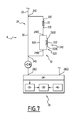
- the operation of the treatment device 6 represented on the figure 7 is then similar to the operation of the treatment device 6 shown in FIG. figure 5 , the delay ⁇ ' 1 replacing the delay ⁇ 1 .
- the second interferometer 240 has a role similar to the role of the second interferometer 24B of the treatment device 6 shown in FIG. figure 5 .
- the second interferometer 240 is arranged between the input 24E of the first interferometer 24 and the input 33E the delay line 33.
- the input 240E of the second interferometer 240 is then connected to the input 24E of the first interferometer 24, and the output 240S of the second interferometer 240 is connected to the input 33E of the delay line 33.
- the first arm 30 of the first interferometer 24 comprises the second interferometer 240.
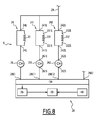
- the processing device 6 comprises at least two interferometers in parallel, for example three interferometers in parallel.
- the processing device 6 comprises a first interferometer 24, as described with regard to the figure 1 , a second interferometer 241 and a third interferometer 242.
- the processing device 6 also comprises a first detector 26, as described with reference to FIG. figure 1 a second detector 261 and a third detector 262.
- the second and third detectors 261, 262 are similar to the first detector 26.
- the second and third interferometers 241, 242 have a structure similar to the structure of the first interferometer 24.
- the second and third interferometers 241, 242 respectively comprise a second delay line 331 and a third delay line 332.
- the second delay line 331 has an input 331 E and an output 331 S.
- the third delay line 332 has an input 332E and an output 332S.
- the second delay line 331 is able to provide at its output 331 S a signal delayed by a time delay ⁇ * 1 with respect to a signal applied to its input 331 E.
- the third delay line 332 is capable of providing at its output 332S a signal delayed by a time delay ⁇ * 2 with respect to a signal applied to its input 332E.
- the lengths of the delay lines 33, 331, 332 are two by two different.
- the ratio between the largest of the delay ⁇ 0 of the delay line 33, the delay ⁇ * 1 of the second delay line 331 and the delay ⁇ * 2 of the third delay line 332, and the most small among these delays ⁇ 0 , ⁇ * 1 , ⁇ * 2 is greater than 2, preferably greater than 5, for example greater than 10.
- the second interferometer 241 comprises an input 241 E, connected to the demodulation fiber 29.
- the second interferometer 241 further comprises an output 241 S connected to an input 261 E of the second detector 261.
- the third interferometer 242 comprises an input 242E, connected to the demodulation fiber 29.
- the second interferometer 242 further comprises an output 242S connected to an input 262E of the second detector 262.
- the processing unit 28 has a second input 28E11 and a third input 28E12.
- the second input 28E11 is connected to an output 261 S of the second detector 261.
- the third input 28E12 is connected to an output 262S of the third detector 262.
- the sampled wave is conveyed by the demodulation fiber 29 from the laser source 9.
- the sampled wave is divided into three waves: a first wave taken, a second wave taken and a third wave taken.
- the first, the second and the third waves sampled are injected at the input 24E, 241E, 242E of the first, second and third interferometers 24, 241, 242 respectively.
- the user chooses a first, a second and a third positive integer number R 1 , R 2 , R 3 , at least one of which is non-zero, and inputs them via the input means 40.
- Each integer number R 1 , R 2 , R 3 is associated with a delay line 33, 331, 332.
- the operation of the treatment device 6 of the figure 8 is then similar to the operation of the treatment device of the figure 1 .
- the computer 38 calculates a reference signal, then a demodulation signal.
- the computer 38 then calculates the demodulated signal, which is equal to the successive product of the signal to be demodulated by each demodulation signal.
- At least one of the interferometers in parallel is in series with another interferometer.
- At least one of the interferometers in parallel comprises a nested interferometer.
- optical waves in such a demodulation process can generate delays for example between 10 ns and 500 ⁇ s. Such delays are capable of compensating for significant propagation distances of the waves from the transmitter 12 to the target 3, then from the target 3 to the receiver 16. For example, such delays are able to compensate for distances of spread between 3 m and 150 km. Such delays are more important than the delays experienced when using microwave waves.
- the electromagnetic wave emitted by the detection system 2 is a microwave wave.
- microwave electromagnetic wave is meant a wave whose frequency is between 0.1 GHz and 10 THz.
- the remote sensing device 4 is then a remote sensing device with radar technology (radio detection and ranging).
- the remote sensing device 4 then comprises components capable of generating, transmitting, receiving, interfering with or detecting microwave electromagnetic waves.
- the emission stage 7 is suitable for generating a microwave wave and for transmitting the microwave wave towards the target 3.
- the reception stage 8 is adapted to receive a microwave signal emitted by the target 3.
- the reception stage 8 is also able to generate an interference signal between the received wave and a portion of the wave generated. by the transmit stage 7.
- the receive stage 8 is further adapted to detect the interference signal to generate a signal to be demodulated.
- the processing device 6 is able to generate a demodulation signal from a portion of the microwave generated by the transmission stage 7, according to the method defined above.
- the processing device 6 comprises at least one interferometer comprising a first arm and a second arm.
- the second arm comprises a delay line, conventionally known, for inducing a predetermined delay in a microwave signal that passes through the delay line.
- the interferometric signal is for example obtained with an electronic mixture.
- the ratio between the largest delay ⁇ 0 , ⁇ 1 , ⁇ ' 1 , ⁇ * 1 , ⁇ * 2 introduced by a delay line 33, 33B, 330, 331 or 332 and the smallest of these delays ⁇ 0 , ⁇ 1 , ⁇ ' 1 , ⁇ * 1 , ⁇ * 2 is preferably greater than 5, preferably greater than 10, for example greater than 20.
Abstract
L'invention concerne un procédé de génération de M signaux de démodulation, comprenant les étapes de : - fourniture de M signaux d'entrée ; - injection de chaque signal d'entrée dans au moins un premier interféromètre (24) ; - détection de M signaux de sortie ; - choix de M nombres entiers positifs non tous nuls ; - calcul de M signaux de démodulation, le i-ième signal de démodulation étant le produit de R i +1 fonctions, R i étant l'entier choisi qui correspond au premier retard du i-ième premier interféromètre (24), la p-ième fonction étant égale à : S i , p t = S ¢ t - p ¢ Ä i où p est un entier compris entre 0 et R i , T i est le premier retard introduit par la ligne à retard du i-ième premier interféromètre (24) et S est une transformée du signal en sortie (24S) du i-ième premier interféromètre (24).The invention relates to a method for generating M demodulation signals, comprising the steps of: - supply of M input signals; - injection of each input signal into at least a first interferometer (24); - detection of M output signals; - choice of M positive whole numbers not all zero; - calculation of M demodulation signals, the i-th demodulation signal being the product of R i +1 functions, R i being the chosen integer which corresponds to the first delay of the i-th first interferometer (24), the p- ith function being equal to: S i, pt = S ¢ t - p ¢ Ä i where p is an integer between 0 and R i, T i is the first delay introduced by the delay line of the i-th first interferometer (24) and S is a transform of the output signal (24S) of the i-th first interferometer (24).
Description
La présente invention concerne un procédé de génération de M signaux de démodulation, M étant un nombre entier strictement positif. L'invention concerne également un procédé de démodulation d'un signal à démoduler par au moins M signaux obtenus par la mise en oeuvre d'un tel procédé, un dispositif propre à mettre en oeuvre un tel procédé de génération de M signaux de démodulation, et un système de détection comprenant un tel dispositif.The present invention relates to a method for generating M demodulation signals, M being a strictly positive integer. The invention also relates to a method for demodulating a signal to be demodulated by at least M signals obtained by the implementation of such a method, a device adapted to implement such a method for generating M demodulation signals, and a detection system comprising such a device.
L'invention s'applique au domaine de la détection et de l'analyse d'au moins une cible par des ondes électromagnétiques, par exemple dans le cadre d'applications radar ou lidar.The invention applies to the field of the detection and analysis of at least one target by electromagnetic waves, for example in the context of radar or lidar applications.
La cible est par exemple une cible dure ou une cible diffuse.The target is for example a hard target or a diffuse target.
Par « cible dure », on entend généralement un objet solide.Hard target is usually a solid object.
Par « cible diffuse », on entend généralement un gaz ou un mélange de gaz, comportant éventuellement des particules en suspension dont les dimensions sont du même ordre de grandeur que la longueur d'onde des ondes électromagnétiques.The term "diffuse target" generally means a gas or a mixture of gases, possibly comprising particles in suspension whose dimensions are of the same order of magnitude as the wavelength of the electromagnetic waves.
Une telle détection a par exemple pour but la mesure de grandeurs physiques relatives à l'atmosphère, la réalisation d'une cartographie de vents, ou encore la réalisation de mesures de distance et/ou de vitesse relatives à une cible dure.Such detection is intended for example the measurement of physical quantities relating to the atmosphere, performing a wind mapping, or the achievement of distance measurements and / or speed relative to a hard target.
De façon classique, une onde électromagnétique est émise, à partir d'une source, à destination de la cible et diffusée par ladite cible en une onde diffusée. Une partie de l'onde diffusée est collectée et analysée pour en déduire les caractéristiques relatives à la cible qui sont recherchées. De préférence, l'analyse effectuée sur l'onde collectée est une analyse spectrale. Plus précisément, des raies sont recherchées dans le spectre de l'onde collectée, la fréquence desdites raies étant représentative d'une grandeur relative à la cible.Conventionally, an electromagnetic wave is emitted, from a source, to the target and broadcast by said target in a broadcast wave. Part of the scattered wave is collected and analyzed to deduce the target characteristics that are sought. Preferably, the analysis performed on the collected wave is a spectral analysis. More precisely, lines are sought in the spectrum of the collected wave, the frequency of said lines being representative of a magnitude relative to the target.
Par « spectre » d'un signal, on entend la densité spectrale de puissance de ce signal.By "spectrum" of a signal is meant the spectral power density of this signal.
La fréquence de l'onde émise étant généralement comprise entre quelques gigahertz et quelques centaines de terahertz, il est préférable de transposer le spectre de l'onde collectée à des fréquences basses pour réaliser cette analyse spectrale, par exemple des fréquences inférieures à quelques gigahertz, pour permettre un traitement par les instruments de mesure usuels afin de détecter les raies décrites précédemment.The frequency of the emitted wave being generally between a few gigahertz and a few hundred terahertz, it is preferable to transpose the spectrum of the collected wave at low frequencies to perform this spectral analysis, for example frequencies lower than a few gigahertz, to allow processing by the usual measuring instruments to detect the lines described above.
A cet effet, il est connu de faire interférer l'onde collectée et partie de l'onde émise, encore appelée « oscillateur local », et d'enregistrer le signal de battement résultant, puis d'effectuer l'étape d'analyse spectrale sur ce signal de battement, généralement en bande de base, ou encore autour d'une fréquence basse prédéterminée égale à la différence entre les porteuses de l'onde collectée et de l'onde émise.For this purpose, it is known to interfere with the collected wave and part of the transmitted wave, also called "local oscillator", and to record the resulting beat signal, then to perform the spectral analysis step on this beat signal, usually in band base, or around a predetermined low frequency equal to the difference between the carriers of the collected wave and the transmitted wave.
Toutefois, les sources d'ondes n'étant pas parfaites, l'onde générée par une source donnée connaît, au cours du temps, des fluctuations, par exemple des fluctuations d'intensité et/ou des fluctuations de la phase temporelle de l'onde générée.However, since the wave sources are not perfect, the wave generated by a given source experiences, over time, fluctuations, for example intensity fluctuations and / or fluctuations in the time phase of the generated wave.
Du fait de ces fluctuations, l'onde collectée à un instant donné a, par exemple, une phase partiellement décorrélée de l'onde émise à ce même instant, avec une partie de laquelle l'onde collectée est mélangée. Cette décorrélation se traduit, par rapport au cas idéal dépourvu de fluctuations, par un élargissement des raies d'intérêt dans le spectre du signal de battement, associé à une baisse de l'intensité des raies.Because of these fluctuations, the wave collected at a given instant has, for example, a partially decorrelated phase of the wave emitted at the same time, with part of which the collected wave is mixed. This decorrelation results, compared to the ideal case devoid of fluctuations, by a widening of the lines of interest in the spectrum of the beat signal, associated with a decrease in the intensity of the lines.
Il est connu de démoduler le signal de battement par un signal de référence prédéterminé, choisi en fonction de la distance à laquelle se trouve la cible. Le signal de référence prédéterminé est adapté pour compenser en partie les fluctuations de la source d'ondes, notamment ses fluctuations de phase.It is known to demodulate the beat signal by a predetermined reference signal, chosen according to the distance to which the target is located. The predetermined reference signal is adapted to partially compensate for the fluctuations of the wave source, in particular its phase fluctuations.
Néanmoins, un tel procédé ne donne pas entière satisfaction.Nevertheless, such a method is not entirely satisfactory.
En effet, le signal de référence n'est pas adapté pour compenser les fluctuations réelles de la source d'ondes au cours du temps. La compensation de l'élargissement des raies d'intérêt est donc limitée.Indeed, the reference signal is not adapted to compensate for the real fluctuations of the wave source over time. The compensation for the widening of the lines of interest is therefore limited.
Un but de l'invention est donc de proposer un procédé de traitement du signal collecté conduisant à un traitement plus efficace de l'élargissement des raies d'intérêt.An object of the invention is therefore to propose a method of processing the collected signal leading to a more efficient treatment of the widening of the lines of interest.
A cet effet, l'invention a pour objet un procédé du type précité, comprenant les étapes de :
- fourniture de M signaux d'entrée ;
- injection de chaque signal d'entrée dans au moins un premier interféromètre, le premier interféromètre comportant :
- une entrée dans laquelle le signal d'entrée est injecté,
- un premier bras et un deuxième bras, le deuxième bras comprenant une première ligne à retard introduisant un premier retard,
- une sortie par laquelle sort un signal d'interférence correspondant à l'interférence entre un signal issu du premier bras et un signal issu du deuxième bras,
- détection de M signaux de sortie, chaque signal de sortie étant un signal dépendant du signal d'interférence obtenu en sortie de chaque premier interféromètre ;
- choix de M nombres entiers positifs non tous nuls ;
- calcul de M signaux de démodulation, le i-ième signal de démodulation étant le produit de Ri+1 fonctions, Ri étant l'entier choisi qui correspond au premier retard du i-ième premier interféromètre, la p-ième fonction étant égale à :

où p est un entier compris entre 0 et Ri, Ti est le premier retard introduit par la ligne à retard du i-ième premier interféromètre et S est une transformée du signal en sortie du i-ième premier interféromètre.
- providing M input signals;
- injecting each input signal into at least a first interferometer, the first interferometer comprising:
- an input in which the input signal is injected,
- a first arm and a second arm, the second arm comprising a first delay line introducing a first delay,
- an output which outputs an interference signal corresponding to the interference between a signal from the first arm and a signal from the second arm,
- detecting M output signals, each output signal being a signal dependent on the interference signal obtained at the output of each first interferometer;
- choice of M positive integers not all zero;
- calculating M demodulation signals, the i-th demodulation signal being the product of R i + 1 functions, R i being the chosen integer corresponding to the first delay of the i-th first interferometer, the p-th function being equal at :
where p is an integer between 0 and R i , T i is the first delay introduced by the delay line of the i-th first interferometer and S is a signal transform at the output of the i-th first interferometer.
Suivant d'autres aspects avantageux de l'invention, le procédé comporte une ou plusieurs des caractéristiques suivantes, prise(s) isolément ou suivant toute combinaison techniquement possible :
- au moins un i-ième premier interféromètre est relié à N deuxièmes interféromètres, N étant un nombre entier strictement positif, le j-ième deuxième interféromètre, j étant un nombre entier compris entre 1 et (N-1), comportant :
- une entrée,
- un premier bras et un deuxième bras, le deuxième bras comprenant une j-ième ligne à retard introduisant un j-ième deuxième retard,
- une sortie par laquelle sort un j-ième signal d'interférence correspondant à l'interférence entre un signal issu du premier bras et un signal issu du deuxième bras du j-ième deuxième interféromètre, la sortie du j-ième deuxième interféromètre étant reliée à l'entrée du (j+1)-ième deuxième interféromètre ;
le procédé comportant en outre les étapes de :- détection du i-ième signal d'interférence obtenu en sortie du N-ième deuxième interféromètre ;
- choix de N nombres entiers positifs non tous nuls ;
- calcul de N signaux de démodulation, le j-ième signal de démodulation étant le produit de Kj+1 fonctions, Kj étant l'entier choisi qui correspond au retard du j-ième troisième interféromètre, la p-ième fonction étant égale à :

où p est un entier compris entre 0 et Kj et S est une transformée du signal en sortie du N-ième troisième interféromètre ;
- au moins un bras d'un interféromètre comporte un troisième interféromètre, le troisième interféromètre comprenant :
- une entrée dans laquelle est injectée une partie du signal d'entrée de l'interféromètre ;
- un premier bras et un deuxième bras, le deuxième bras comprenant une ligne à retard introduisant un troisième retard ;
- une sortie par laquelle sort un deuxième signal d'interférence correspondant à l'interférence entre un signal issu du premier bras de l'interféromètre et un signal issu du deuxième bras de l'interféromètre ;
- le rapport entre le plus grand retard introduit par une ligne à retard et le plus petit retard introduit par une autre ligne à retard est de préférence supérieur à 5, de préférence supérieur à 10, par exemple supérieur à 20 ;
- le signal d'entrée provient d'un dispositif de télédétection présentant une portée prédéterminée, et dans lequel au moins une ligne à retard est une fibre optique dont la longueur est de préférence inférieure ou égale à la portée, avantageusement inférieure au cinquième de la portée, par exemple inférieure au dixième de la portée.
- at least one i-th first interferometer is connected to N second interferometers, N being a strictly positive integer, the j-th second interferometer, j being an integer between 1 and (N-1), comprising:
- an entrance,
- a first arm and a second arm, the second arm comprising a j-th delay line introducing a jth second delay,
- an output by which a j-th interference signal corresponding to the interference between a signal coming from the first arm and a signal coming from the second arm of the j-th second interferometer, the output of the j-th second interferometer being connected to the input of the (j + 1) second interferometer;
the method further comprising the steps of:- detecting the i-th interference signal obtained at the output of the N-th second interferometer;
- choice of N positive integers not all zero;
- calculating N demodulation signals, the jth demodulation signal being the product of K j +1 functions, K j being the chosen integer corresponding to the delay of the jth third interferometer, the p-th function being equal to :
where p is an integer between 0 and K j and S is a signal transform at the output of the Nth third interferometer;
- at least one arm of an interferometer comprises a third interferometer, the third interferometer comprising:
- an input into which is injected a portion of the input signal of the interferometer;
- a first arm and a second arm, the second arm comprising a delay line introducing a third delay;
- an output which outputs a second interference signal corresponding to the interference between a signal from the first arm of the interferometer and a signal from the second arm of the interferometer;
- the ratio between the largest delay introduced by a delay line and the smallest delay introduced by another delay line is preferably greater than 5, preferably greater than 10, for example greater than 20;
- the input signal comes from a remote sensing device having a predetermined range, and wherein at least one delay line is an optical fiber whose length is preferably less than or equal to the range, advantageously less than one-fifth of the range , for example less than one-tenth of the litter.
En outre, l'invention a pour objet un procédé de démodulation, comprenant les étapes de :
- fourniture d'un signal à démoduler ;
- démodulation successive du signal à démoduler par au moins M signaux de démodulation obtenus par la mise en oeuvre du procédé de génération de M signaux de démodulation tel que défini ci-dessus.
- providing a signal to be demodulated;
- successive demodulation of the signal to be demodulated by at least M demodulation signals obtained by implementing the method for generating M demodulation signals as defined above.
En outre, l'invention a pour objet l'utilisation du procédé de démodulation tel que défini ci-dessus pour la détermination de la vitesse et de la position d'une cible.In addition, the subject of the invention is the use of the demodulation method as defined above for determining the speed and the position of a target.
En outre, l'invention a pour objet un dispositif de génération de M signaux de démodulation, M étant un nombre entier strictement positif, comprenant :
- M premiers interféromètres, chaque premier interféromètre comportant :
- une entrée propre à recevoir un signal injecté ;
- un premier bras et un deuxième bras, le deuxième bras comprenant une première ligne à retard propre à introduire un premier retard ;
- une sortie propre à fournir un signal d'interférence correspondant à l'interférence entre un signal issu du premier bras et un signal issu du deuxième bras ;
- M détecteurs, chaque détecteur étant propre à détecter un signal dépendant du signal d'interférence obtenu en sortie de chaque premier interféromètre ;
- une unité de traitement propre à calculer M signaux de démodulation, le i-ième signal de démodulation étant le produit de Ri+1 fonctions, Ri étant un entier prédéterminé correspondant au premier retard du i-ième premier interféromètre, la p-ième fonction étant égale à :

où p est un entier compris entre 0 et Ri, τi est le premier retard que la ligne à retard du i-ième premier interféromètre est propre à introduire et S est une transformée du signal en sortie du i-ième premier interféromètre.
- M first interferometers, each first interferometer comprising:
- an input adapted to receive an injected signal;
- a first arm and a second arm, the second arm comprising a first delay line capable of introducing a first delay;
- an output adapted to provide an interference signal corresponding to the interference between a signal from the first arm and a signal from the second arm;
- M detectors, each detector being able to detect a signal depending on the interference signal obtained at the output of each first interferometer;
- a processing unit adapted to calculate M demodulation signals, the i-th demodulation signal being the product of R i + 1 functions, R i being a predetermined integer corresponding to the first delay of the i-th first interferometer, the p-th function being equal to:
where p is an integer between 0 and R i , τ i is the first delay that the delay line of the i-th first interferometer is adapted to introduce and S is a signal transform at the output of the i-th first interferometer.
En outre, l'invention a pour objet un système de détection, en particulier lidar ou radar, comportant :
- un étage d'émission d'une onde électromagnétique vers une cible ;
- un étage de réception d'une onde électromagnétique diffusée par la cible ;
- un dispositif de génération d'au moins un signal de démodulation tel que défini ci-dessus pour démoduler un signal électrique qui est fonction de l'onde diffusée reçue par l'étage de réception.
- an emission stage of an electromagnetic wave towards a target;
- a reception stage of an electromagnetic wave diffused by the target;
- a device for generating at least one demodulation signal as defined above for demodulating an electrical signal which is a function of the scattered wave received by the reception stage.
L'invention sera mieux comprise à l'aide de la description qui va suivre, donnée uniquement à titre d'exemple non limitatif et faite en se référant aux dessins annexés sur lesquels :
- la
figure 1 est une représentation schématique d'un premier système de détection comprenant un premier dispositif de traitement selon l'invention ; - la
figure 2 est un spectre d'un signal avant la mise en oeuvre du procédé de traitement selon l'invention ; - la
figure 3 est un graphe d'un signal de référence obtenu par la mise en oeuvre du procédé de traitement selon l'invention ; - la
figure 4 est un spectre issu du signal de lafigure 2 , après la mise en oeuvre du procédé de traitement ; - la
figure 5 est une représentation schématique d'un deuxième système de détection comprenant un deuxième dispositif de traitement selon l'invention ; - la
figure 6 est une représentation schématique d'un troisième système de détection mettant en oeuvre le dispositif de traitement de lafigure 1 ; - la
figure 7 est une représentation schématique d'une partie d'un quatrième système de détection selon l'invention ; et - la
figure 8 est une représentation schématique d'une partie d'un cinquième système de détection selon l'invention.
- the
figure 1 is a schematic representation of a first detection system comprising a first processing device according to the invention; - the
figure 2 is a spectrum of a signal before the implementation of the treatment method according to the invention; - the
figure 3 is a graph of a reference signal obtained by the implementation of the treatment method according to the invention; - the
figure 4 is a spectrum from the signal of thefigure 2 after the implementation of the treatment method; - the
figure 5 is a schematic representation of a second detection system comprising a second processing device according to the invention; - the
figure 6 is a schematic representation of a third detection system implementing the device for processing thefigure 1 ; - the
figure 7 is a schematic representation of a portion of a fourth detection system according to the invention; and - the
figure 8 is a schematic representation of part of a fifth detection system according to the invention.
Un système de détection et d'analyse 2 est représenté sur la
Le système de détection 2 est propre à interagir avec une cible 3. Notamment, le système de détection 2 est propre à émettre une onde électromagnétique vers la cible 3. La cible 3 est propre à diffuser l'onde électromagnétique émise par le système de détection 2.The
La cible 3 est par exemple une cible dure ou une cible diffuse. La cible 3 est mobile ou immobile.The
En outre, le système de détection 2 est propre à recevoir l'onde électromagnétique diffusée par la cible 3.In addition, the
L'onde électromagnétique émise par le système de détection 2 est par exemple une onde optique.The electromagnetic wave emitted by the
Par « onde optique », on entend une onde électromagnétique dont la longueur d'onde dans le vide est comprise entre 100 nm et 20 µm.By "optical wave" is meant an electromagnetic wave whose wavelength in vacuum is between 100 nm and 20 microns.
Le système de détection 2 comporte un dispositif de télédétection 4 à technologie lidar (de l'anglais « light détection and ranging ») et un dispositif de traitement 6 selon l'invention.The
Le dispositif de télédétection 4 est adapté pour émettre et recevoir des ondes optiques, et pour générer un signal électrique qui est fonction des ondes optiques reçues. Le dispositif de traitement 6 est propre à générer un signal de démodulation pour démoduler ledit signal électrique généré par le dispositif de télédétection 4 et à réaliser cette démodulation.The
Plus précisément, le dispositif de télédétection 4 comporte un étage d'émission 7 pour émettre une onde optique en direction de la cible 3, et un étage de réception 8 pour recevoir l'onde optique diffusée par la cible 3 et générer un signal électrique qui est fonction de l'onde optique diffusée reçue.More precisely, the
L'étage d'émission 7 comporte une source laser 9 propre à générer une onde optique, un amplificateur optique 11 propre à amplifier l'onde optique, et un émetteur 12 propre à émettre vers la cible 3 l'onde optique amplifiée.The
En variante, l'étage d'émission 7 ne comporte pas d'amplificateur optique.In a variant, the
La source laser 9 comprend une sortie 9S reliée par une première fibre optique 10 à une entrée 11 E de l'amplificateur 11. En outre, une sortie 11S de l'amplificateur 11 est reliée par une fibre optique d'émission 14 à une entrée 12E de l'émetteur 12.The
La source laser 9 est propre à générer une onde optique dont la longueur d'onde dans le vide centrale est avantageusement comprise entre 1,4 µm et 1,6 µm, par exemple égale à 1,55 µm.The
La source laser 9 comporte de préférence une unité de pilotage, non représentée, pour modifier la fréquence de l'onde optique émise par la source laser 9 au cours du temps. Par exemple, l'unité de pilotage est adaptée pour faire varier au cours du temps la fréquence de l'onde émise par la source laser 9 en suivant un profil en dents de scie, avec une amplitude égale à quelques centaines de mégahertz et une période égale à quelques dizaines de microsecondes. De façon optionnelle, l'unité de pilotage est également adaptée pour modifier l'amplitude de l'onde optique émise par la source laser 9 au cours du temps.The
La source laser 9 est par exemple une diode laser telle qu'une diode laser à rétroaction répartie (ou DFB, de l'anglais « distributed feedback »).The
La première fibre optique 10 est préférentiellement une fibre à maintien de polarisation, avantageusement une fibre monomode à maintien de polarisation.The first
L'amplificateur 11 est propre à amplifier l'onde émise par la source laser 9 et injectée à son entrée 11 E. L'amplificateur 11 est adapté pour fournir à sa sortie 11S une onde amplifiée dont la fréquence est sensiblement égale à la fréquence de l'onde injectée à son entrée 11 E. L'amplificateur 11 est par exemple un amplificateur à fibre ou un amplificateur optique à semiconducteur (ou SOA, de l'anglais « Semiconductor Optical Amplifier »).The
L'émetteur 12 est propre à modifier l'onde optique amplifiée injectée à son entrée 12E pour lui conférer des propriétés de phase spatiale et/ou d'amplitude spatiale et/ou de polarisation souhaitées par un utilisateur. Par exemple, l'émetteur 12 est propre à focaliser à une distance prédéterminée, appelée « portée » du dispositif de télédétection 4, l'onde optique amplifiée injectée à son entrée 12E.The
L'étage de réception 8 comporte un récepteur 16 pour recevoir l'onde diffusée, un coupleur 18 pour faire interférer l'onde diffusée reçue avec une autre onde optique, et un premier détecteur 20, encore appelée « détecteur principal », pour détecter un signal optique d'interférence et générer un courant électrique qui est fonction du signal optique d'interférence.The
Le récepteur 16 comporte une sortie 16S, reliée à une première entrée 18E1 du coupleur 18 par une fibre optique de réception 22. Le coupleur 18 comporte une deuxième entrée 18E2 reliée à la sortie 9S de la source laser 9 par une fibre optique 23, dite « fibre d'oscillateur local », adaptée pour acheminer une partie de l'onde optique en sortie de la source laser 9 vers la deuxième entrée 18E2 du coupleur optique 18.The
La première fibre optique de réception 22 est préférentiellement une fibre à maintien de polarisation, avantageusement une fibre monomode à maintien de polarisation. En outre, la fibre d'oscillateur local 23 est préférentiellement une fibre à maintien de polarisation, avantageusement une fibre monomode à maintien de polarisation.The first
En variante, la fibre d'oscillateur local 23 relie la deuxième entrée 18E2 du coupleur 18 à la sortie 11S de l'amplificateur 11 pour acheminer une partie de l'onde optique amplifiée en sortie de l'amplificateur 11 vers la deuxième entrée 18E2.In a variant, the
Le coupleur 18 comporte en outre une première sortie 18S1, reliée à une entrée 20E du détecteur 20, et une deuxième sortie 18S2, non reliée sur cette figure.The
Le récepteur 16 est propre à modifier l'onde diffusée reçue pour fournir à sa sortie 16S une onde optique possédant des propriétés de phase spatiale et/ou d'amplitude spatiale et/ou de polarisation souhaitées par un utilisateur.The
Le coupleur 18 possède par exemple un facteur de couplage égal à 3 dB, c'est-à-dire que le coupleur 18 est propre à fournir à chacune de ses sorties 18S1, 18S2 une onde optique égale à la moitié de la somme de l'onde optique injectée à sa première entrée 18E1, et de l'onde optique injectée à sa deuxième entrée 18E2.The
Le détecteur principal 20 est propre à fournir à sa sortie 20S un signal électrique, encore appelé « signal à démoduler », qui dépend du signal optique appliqué à son entrée 20E par la première sortie 18S1, avantageusement un signal électrique proportionnel à la puissance optique du signal optique appliqué à son entrée 20E.The
Le détecteur principal 20 est, par exemple, une photodiode ou un photomultiplicateur.The
Le dispositif de traitement 6 comporte un interféromètre 24 pour fournir un signal optique de référence à partir d'une partie de l'onde optique générée par la source laser 9, un deuxième détecteur 26, encore appelé « détecteur de démodulation » pour détecter le signal optique de référence et générer un signal électrique, encore appelé « signal de référence », qui est fonction de l'onde optique de référence, et une unité de traitement 28 pour traiter le signal de référence.The
L'interféromètre 24 comporte une entrée 24E, reliée par une fibre optique 29, encore appelée « fibre de démodulation », à la sortie 9S de la source laser 9, et une sortie 24S reliée à une entrée 26E du détecteur de démodulation 26. Le détecteur de démodulation 26 comporte en outre une sortie 26S, reliée à une première entrée 28E1 de l'unité de traitement 28. L'unité de traitement 28 comporte en outre une entrée de démodulation 28E2 reliée à la sortie 20S sortie du détecteur principal 20.The
La fibre de démodulation 29 est préférentiellement une fibre à maintien de polarisation, avantageusement une fibre monomode à maintien de polarisation.The
L'interféromètre 24 comporte un premier bras 30 et un deuxième bras 32 de longueurs distinctes.The
Le deuxième bras 32 comporte une ligne à retard 33 comportant une entrée 33E et une sortie 33S. La ligne à retard 33 est propre à fournir à sa sortie 33S un signal retardé d'un retard temporel T0 par rapport à un signal appliqué à son entrée 33E.The
La ligne à retard 33 est par exemple une fibre optique, préférentiellement une fibre monomode, avantageusement une fibre monomode à maintien de polarisation.The
La longueur de la ligne à retard 33 est de préférence inférieure ou égale à la portée du dispositif de télédétection 4, avantageusement inférieure au cinquième de la portée, par exemple inférieure au dixième de la portée. Par exemple, la longueur de la ligne à retard 33 est inférieure à 40 mètres, avantageusement inférieure à 20 mètres, par exemple inférieure à 10 mètres.The length of the
De préférence, l'interféromètre 24 est tel qu'une onde optique injectée à son entrée 24E se divise en deux ondes optiques : une première onde optique circulant dans le premier bras 30 et une deuxième onde optique circulant dans le deuxième bras 32. La puissance optique de la deuxième onde optique est comprise entre 45% et 55% de la puissance optique de la première onde optique, préférentiellement égale.Preferably, the
L'interféromètre 24 est par exemple un interféromètre de Mach-Zehnder.The
L'unité de traitement 28 comprend un système d'acquisition 34 comportant deux entrées qui sont les entrées 28E1, 28E2 de l'unité de traitement 28, une mémoire 36 et un calculateur 38. L'unité de traitement comporte en outre des moyens de saisie 40.The
Le système d'acquisition 34 de l'unité de traitement 28 est adapté pour échantillonner chacun des signaux électriques appliqués à ses entrées 28E1, 28E2. Le système d'acquisition 34 est également adapté pour transmettre les signaux échantillonnés à la mémoire 36.The
La mémoire 36 est adaptée pour stocker les signaux échantillonnés par le système d'acquisition 34.The
Le calculateur 38 est adapté pour traiter les données stockées dans la mémoire 36, par exemple traiter les données en fonction d'instructions saisies par un utilisateur par l'intermédiaire des moyens de saisie 40. En particulier, le calculateur 38 est adapté pour calculer un signal de démodulation à partir du signal appliqué à la première entrée 28E1 de l'unité de traitement 28, et pour démoduler le signal à démoduler, appliqué à l'entrée de démodulation 28E2 de l'unité de traitement 28, par le signal de démodulation calculé.The
Avantageusement, le calculateur 38 est adapté pour se synchroniser sur l'unité de pilotage de la source laser 9. Par exemple, le calculateur 38 est adapté pour traiter séparément les signaux reçus durant la partie croissante de la modulation en dent de scie et les signaux reçus durant la partie décroissante de cette modulation.Advantageously, the
Le fonctionnement du système de détection 2 va maintenant être décrit en regard des
La source laser 9 émet une onde optique dont la fréquence est commandée par l'unité de pilotage. Toutefois, la phase de l'onde optique fluctue au cours du temps.The
Une première partie de l'onde optique émise par la source laser 9 se propage dans la première fibre optique 10 jusqu'à l'amplificateur 11.A first portion of the optical wave emitted by the
En outre, une deuxième partie de l'onde émise par la source laser 9, encore appelée « oscillateur local », se propage dans la fibre d'oscillateur local 23 jusqu'à la deuxième entrée 18E2 du mélangeur 18.In addition, a second portion of the wave emitted by the
En outre, une troisième partie de l'onde émise par la source laser 9, dite « onde prélevée », se propage dans la fibre de démodulation 29 jusqu'à l'interféromètre 24.In addition, a third part of the wave emitted by the
L'amplificateur 11 amplifie la première partie de l'onde émise par la source laser 9 et fournit à sa sortie 11S une onde optique amplifiée.The
L'émetteur 12 émet l'onde amplifiée en direction de la cible 3.The
La cible 3 diffuse l'onde amplifiée émise par l'émetteur 12. Le spectre de l'onde diffusée présente des propriétés représentatives de paramètres physiques de la cible 3 tels que sa position ou sa vitesse.The
En effet, le décalage temporel entre les motifs en dents de scie de l'onde émise et les motifs en dents de scie de l'onde diffusée est proportionnel à la distance à laquelle se trouve la cible 3.Indeed, the time difference between the sawtooth patterns of the emitted wave and the sawtooth patterns of the scattered wave is proportional to the distance to which the
En effet, le décalage fréquentiel entre les maxima des motifs en dents de scie de l'onde émise et les maxima des motifs en dents de scie de l'onde diffusée est proportionnel à la vitesse de la cible 3.Indeed, the frequency offset between the maxima of the sawtooth patterns of the emitted wave and the maxima of the sawtooth patterns of the scattered wave is proportional to the speed of the
Le récepteur 16 capte une partie de l'onde diffusée par la cible 3. L'onde captée injectée dans la première entrée 18E1 du coupleur 18 via la fibre de réception 20.The
Le coupleur 18 fournit à sa sortie une onde optique par exemple égale à la moitié de la somme de l'onde injectée dans la première entrée du coupleur 18 par la fibre d'oscillateur local 23 et de l'onde reçue injectée dans la deuxième entrée du coupleur 18 par la fibre de réception 20. L'onde optique disponible à la sortie du coupleur 18 est donc un signal optique d'interférence entre les ondes injectées à la première et à la deuxième entrées 18E1, 18E2 du coupleur 18.The
Le détecteur principal 20 détecte le signal optique d'interférence et fournit à sa sortie un signal réel, encore appelé « signal à démoduler », qui est proportionnel au module au carré du signal optique d'interférence injecté à l'entrée du détecteur 22.The
Le signal à démoduler est appliqué à la deuxième entrée de l'unité de traitement 28. Le signal à démoduler est acquis et échantillonné par le système d'acquisition 34 pour être enregistré dans la mémoire 36.The signal to be demodulated is applied to the second input of the
Le signal à démoduler présente un spectre 42, représenté sur la
Le spectre 42 est obtenu par émission d'une onde optique de puissance optique égale à 200 mW vers une cible 3 présentant un albédo égal à 12% et distante de 125 m, après application à la source laser 9 d'une modulation de fréquence linéaire de pente égale à 45 MHz/µs.The
Au sens de la présente invention, une puissance P, en watt, s'exprime en dBm selon la formule: P(dBm) = 10 log[P(mW)/1 mW], log étant l'opérateur logarithme décimal.Within the meaning of the present invention, a power P, in watt, is expressed in dBm according to the formula: P (dBm) = 10 log [P (mW) / 1 mW], log being the logarithmic operator decimal.
Le pic d'intérêt 44 ne possède pas une finesse et un rapport signal sur bruit suffisants pour assurer une estimation précise de sa fréquence centrale. Une estimation précise de la fréquence centrale du pic d'intérêt 44 conduit alors à une estimation précise de la vitesse et/ou de la distance de la cible 3.The peak of
L'onde prélevée est injectée à l'entrée 24E de l'interféromètre 24. Une première partie de l'onde prélevée se propage dans le premier bras 30 de l'interféromètre 24. Une deuxième partie de l'onde prélevée se propage dans le deuxième bras 32 de l'interféromètre 24, notamment dans la ligne à retard 33.The sampled wave is injected at the
L'interféromètre 24 fournit à sa sortie 24S un signal optique de battement, dit « onde de battement ». L'onde de battement résulte de l'interférence entre la première partie de l'onde prélevée et la deuxième partie de l'onde prélevée, retardée du retard τ0 induit par la ligne à retard 33.The
Le détecteur de démodulation 26 détecte l'onde de battement et fournit à sa sortie un signal réel 46, encore appelé « signal de référence », visible sur la
Le signal de référence 46 est appliqué à la première entrée de l'unité de traitement 28. Le signal de référence 46 est acquis et échantillonné par le système d'acquisition 34 pour être enregistré dans la mémoire 36.The
Un utilisateur choisit un nombre entier strictement positif K et le saisit via les moyens de saisie 40.A user chooses a strictly positive integer K and enters it via the input means 40.
Le calculateur 38 calcule alors un signal de référence complexe à partir du signal de référence réel 46.The
Le calculateur 38 calcule d'abord la transformée de Fourier du signal de référence réel 46. Puis le calculateur 38 calcule un signal intermédiaire, obtenu en annulant certaines composantes de la transformée de Fourier du signal de référence. De préférence, le calculateur 38 annule des composantes dont les fréquences sont de même signe. Par exemple, le calculateur 38 calcule le signal intermédiaire en annulant les composantes de fréquence négative de la transformée de Fourier du signal de référence. Le calculateur 38 calcule enfin le signal de référence complexe, qui est égal à la transformée de Fourier inverse du signal intermédiaire.The
Le signal de référence complexe est appelé représentation analytique du signal.The complex reference signal is called the analytic representation of the signal.
En variante, le signal de référence complexe est obtenu en calculant d'abord, dans le calculateur 38, la transformée de Hilbert, classiquement connue, du signal de référence réel 46, puis en additionnant au signal de référence réel 46 sa transformée de Hilbert précédemment calculée.As a variant, the complex reference signal is obtained by first calculating, in the
De préférence, lors du calcul du signal intermédiaire, le calculateur 38 annule également la composante de fréquence nulle de la transformée de Fourier du signal de référence réel.Preferably, during the calculation of the intermediate signal, the
Le signal de référence est alors proportionnel au signal complexe S(t) de module unitaire suivant : ![]()
où ϕ est la phase de l'onde émise par la source laser 9 et τ0 le retard entre le premier bras 30 et le deuxième bras 32 de l'interféromètre 24, ou proportionnel au conjugué de S(t).The reference signal is then proportional to the complex signal S (t) of the following unitary module: ![]()
where φ is the phase of the wave emitted by the
Le calculateur 38 crée ensuite K+1 signaux de transition Sp, chaque signal de transition Sp étant défini sur l'intervalle temporel [0 ; τ0] et s'écrivant : ![]()
![]()
Ainsi, le calculateur 38 a créé : 
Le calculateur 32 calcule ensuite un signal de démodulation Sd égal au produit des K+1 signaux de transition.The
Dans l'exponentielle complexe, tous les termes en ϕ(t-pτ0), avec p un nombre entier quelconque compris entre 0 et K+1, s'annulent, à l'exception de ϕ(t) et ϕ(t-(K+1)τ0) : 
L'expression du signal de démodulation Sd est analogue à celle d'un signal de référence obtenu avec un interféromètre dont le deuxième bras comporte une ligne à retard introduisant un retard (K+1)τ0 entre son entrée et sa sortie.The expression of the demodulation signal S d is analogous to that of a reference signal obtained with an interferometer whose second arm comprises a delay line introducing a delay (K + 1) τ 0 between its input and its output.
Le calculateur 38 calcule ensuite un signal démodulé égal au produit du signal à démoduler et du signal de démodulation Sd, ou encore au produit du signal à démoduler et du conjugué du signal de démodulation Sd..The
L'utilisateur peut ajuster la valeur de l'entier positif K de sorte que le retard (K+1)τ0 induit par le signal de démodulation Sd compense la décorrélation temporelle entre le signal diffusé collecté et l'oscillateur local, de façon à augmenter le rapport signal sur bruit et la finesse du pic d'intérêt 44.The user can adjust the value of the positive integer K so that the delay (K + 1) τ 0 induced by the demodulation signal S d compensates the time decorrelation between the collected broadcast signal and the local oscillator, so to increase the signal-to-noise ratio and the fineness of the peak of
Le signal démodulé présente un spectre 48, représenté sur la
Le pic d'intérêt 50 du spectre 48 du signal démodulé présente une amplitude égale à -119 dBm, avec un rapport signal sur bruit égal à 24 dB, et une largeur à mi-hauteur inférieure à 200 kHz.The peak of
Le pic d'intérêt 50 possède une finesse et un rapport signal sur bruit suffisants pour assurer une estimation précise de la vitesse de la cible 3.The peak of
Selon un deuxième mode de réalisation du système de détection 2 selon l'invention, le dispositif de traitement 6 comporte un deuxième interféromètre 24B, comme cela apparaît sur la
Le deuxième interféromètre 24B est par exemple un interféromètre de Mach-Zehnder.The
Le deuxième interféromètre 24B comprend une entrée 24BE, reliée à la sortie 24S du premier interféromètre 24, et une sortie 24BS reliée à l'entrée 26E du détecteur de démodulation 26.The
Le deuxième interféromètre 24B comporte un premier bras 30B et un deuxième bras 32B de longueurs distinctes.The
Le deuxième bras 32B comporte une deuxième ligne à retard 33B comportant une entrée 33BE et une sortie 33BS. La deuxième ligne à retard 33B est propre à fournir à sa sortie 33BS un signal retardé d'un deuxième retard temporel τ1 par rapport à un signal appliqué à son entrée 33BE.The second arm 32B includes a
La deuxième ligne à retard 33B est par exemple une fibre optique, préférentiellement une fibre à maintien de polarisation, avantageusement une fibre monomode à maintien de polarisation.The
La longueur de la deuxième ligne à retard 33B est différente de la longueur de la ligne à retard 33. De préférence, le rapport entre le premier retard τ0 et le deuxième retard τ1 est supérieur à 5, de préférence supérieur à 10, par exemple supérieur à 20.The length of the
De préférence, chaque interféromètre 24, 24B est tel qu'une onde optique injectée à l'entrée 24E, 24BE de l'interféromètre 24, 24B se divise en une première onde optique circulant dans le premier bras 30, 30B et une deuxième onde optique circulant dans le deuxième bras 32, 32B. La puissance optique de la deuxième onde optique est supérieure à la puissance optique de la première onde optique, avantageusement deux fois supérieure, de préférence cinq fois supérieure, par exemple dix fois supérieure.Preferably, each
En fonctionnement, le premier interféromètre 24 fournit à sa sortie 24S un premier signal optique de battement résultant de l'interférence entre la première partie de l'onde prélevée et la deuxième partie de l'onde prélevée, retardée du retard τ0 induit par la ligne à retard 33.In operation, the
A la différence du mode de réalisation décrit précédemment, le premier signal optique de battement est ensuite injecté à l'entrée 24BE du deuxième interféromètre 24B. Une première partie du premier signal optique de battement se propage dans le premier bras 30B du deuxième interféromètre 24B. Une deuxième partie du premier signal optique de battement se propage dans le deuxième bras 32B du deuxième interféromètre 24B, notamment dans la deuxième ligne à retard 33B.Unlike the embodiment described above, the first beat optical signal is then injected at the input 24BE of the
Le deuxième interféromètre 24B fournit à sa sortie 24BS un deuxième signal optique de battement résultant de l'interférence entre la première partie du premier signal optique de battement et la deuxième partie de la première onde optique de battement, retardée du retard τ1 induit par la deuxième ligne à retard 33B.The
Le détecteur de démodulation 26 détecte le deuxième signal optique de battement et fournit à sa sortie le signal de référence. Le signal de référence est un signal électrique proportionnel au module au carré du deuxième signal optique de battement injecté à l'entrée du détecteur de démodulation 26.The
L'utilisateur choisit un premier et un deuxième nombres entiers positifs K1, K2 dont l'un au moins est non nul, et les saisit via les moyens de saisie 40.The user chooses first and second positive integers K 1 , K 2 , at least one of which is non-zero, and inputs them via the input means 40.
Le calculateur 38 crée ensuite (Ki+1) premiers signaux de transition S1,p et (K2+1) deuxièmes signaux de transition S2,r.The
Les premiers signaux de transition S1,p sont définis comme les signaux de transition Sp décrits précédemment.The first transition signals S 1, p are defined as the transition signals S p described above.
Chaque deuxième signal de transition S2,r est défini sur l'intervalle temporel [0 ; τ1] et s'écrit : ![]()
![]()
S étant le signal de référence défini précédemment.S being the reference signal defined previously.
Le calculateur 32 calcule ensuite un premier signal de démodulation S1,d égal au produit des (K1+1) premiers signaux de transition, et un deuxième signal de démodulation S2,d égal au produit des (K2+1) deuxièmes signaux de transition : 

Le calculateur 38 calcule ensuite le signal démodulé égal au produit du signal à démoduler par le premier signal de démodulation S1,d, ou par son conjugué, puis par le deuxième signal de démodulation S2,d ou par son conjugué, selon le choix de l'utilisateur.The
Ces démodulations successives peuvent s'interpréter comme l'introduction d'un retard total égal à [±(K1+1)τ0 + ±(K2+1)τ1] dans l'oscillateur local avant son injection à la deuxième entrée 18E2 du coupleur 18. L'utilisateur peut ajuster la valeur des entiers K1, K2 de sorte que le retard total [±(K1+1)τ0 + ±(K2+1)τ1] soit aussi proche que possible du temps T de propagation des ondes depuis l'émetteur 12 jusqu'à la cible 3, puis depuis la cible 3 jusqu'au récepteur 16. La démodulation par le conjugué du signal de démodulation S1,d, S2,d revient à introduire un retard négatif.These successive demodulations can be interpreted as the introduction of a total delay equal to [± (K 1 +1) τ 0 + ± (K 2 +1) τ 1 ] in the local oscillator before its injection at the second 18E2 input of the
Ceci a pour effet de compenser la décorrélation temporelle entre l'oscillateur local et le signal diffusé collecté, qui est retardé de T par rapport à l'oscillateur local.This has the effect of compensating the temporal decorrelation between the local oscillator and the collected scattered signal, which is delayed by T relative to the local oscillator.
Les retards τ0, τ1 étant différents, de préférence dans un rapport du premier retard τ0 sur le deuxième retard τ1 supérieur à 5, l'utilisateur peut d'abord choisir la valeur de l'entier correspondant au plus grand retard parmi les deux retards τ0 et τ1 pour approcher grossièrement le temps total de propagation T, puis choisir la valeur de K2 pour approcher plus finement le temps total de propagation T après que la valeur de K1 a été choisie.The delays τ 0 , τ 1 being different, preferably in a ratio of the first delay τ 0 on the second delay τ 1 greater than 5, the user can first choose the value of the integer corresponding to the largest delay among the two delays τ 0 and τ 1 to roughly approximate the total propagation time T, then choose the value of K 2 to approach more finely the total propagation time T after the value of K1 has been chosen.
Selon un troisième mode de réalisation du système de détection 2 selon l'invention, l'émetteur 12 et le récepteur 16 sont confondus en un émetteur-récepteur 42, comme cela apparaît sur la
L'émetteur-récepteur 42 est adapté pour émettre une onde électromagnétique vers la cible 3. L'émetteur-récepteur 42 est également adapté pour recevoir au moins une partie de l'onde électromagnétique diffusée par la cible 3.The
L'émetteur-récepteur 42 comporte une entrée-sortie 42ES.The
Le dispositif de télédétection 4 comporte alors un circulateur 44. Le circulateur 44 comporte une entrée 44E, une sortie 44S et une entrée-sortie 44ES. Le circulateur 44 est propre à acheminer une onde optique injectée à son entrée 44E vers son entrée-sortie 44ES. En outre, le circulateur 44 est propre à acheminer une onde optique injectée à son entrée-sortie 44ES vers sa sortie 44S.The
L'entrée-sortie 44ES du circulateur 44 est reliée à l'entrée-sortie 42ES de l'émetteur-récepteur 42.The input-output 44ES of the
L'émetteur-récepteur 42 comporte par exemple une lentille 46 en série avec une lame quart d'onde 48.The
La lentille 46 est par exemple une lentille convergente.The
Le circulateur 44 est par exemple un circulateur fibré ou un ensemble formé par un cube polariseur, un séparateur de polarisation et une lame d'onde.The
En outre, la fibre d'oscillateur local est remplacée par une ligne à retard de compensation 50, comprenant une entrée 50E et une sortie 50S.In addition, the local oscillator fiber is replaced by a
La ligne à retard de compensation 50 est reliée à la sortie 9S de la source laser 9 en un point de connexion 52. La sortie 50S de la ligne à retard de compensation 50 est reliée à l'entrée 24E de l'interféromètre 24. La sortie 50S est en outre reliée à la deuxième entrée 18E2 du coupleur 18.The
La ligne à retard de compensation 50 induit un retard R prédéterminé entre un signal injectée à son entrée 50E et un signal émergeant de sa sortie 50S. Le retard R est choisi égal au temps total de propagation d'une onde du point de connexion 52 à l'émetteur-récepteur 42, puis de l'émetteur-récepteur 42 à la première entrée 18E1 du coupleur.The
Le retard R permet une compensation préliminaire, sans calcul par l'unité de traitement 28, de la décorrélation entre l'oscillateur local et le signal collecté par le dispositif de télédétection 4. Une telle compensation permet à utilisateur, pour un retard τ0 donné de l'interféromètre 24, de réduire la valeur de l'entier K qui conduit à un affinement recherché des pics d'intérêts 44. Ceci a pour conséquence de réduire les temps de calcul du calculateur 38.The delay R allows a preliminary compensation, without calculation by the
Comme cela apparaît sur la figure, le détecteur 20 du dispositif de télédétection 4 est un détecteur balancé. Le détecteur 20 comprend une première entrée 20E1, une deuxième entrée 20E2 et une sortie 20S. La première entrée 20E1 est reliée à la première sortie 18S1 du coupleur 18. La deuxième entrée 20E2 est reliée à la deuxième sortie 18S2 du coupleur 18.As shown in the figure, the
Le détecteur balancé 20 est par exemple constitué de deux photodiodes de caractéristiques physiques similaires, montées en antiparallèle.The
En variante, l'oscillateur local est prélevé en sortie de l'amplificateur 11, le point de connexion 52 se situant alors en aval de l'amplificateur 11.In a variant, the local oscillator is taken at the output of the
En variante, le dispositif de traitement 6 comporte N interféromètres, N étant un entier naturel strictement supérieur à 2. Les N interféromètres sont alors disposés successivement, la sortie d'un interféromètre étant reliée à la sortie de l'interféromètre suivant.In a variant, the
Chaque interféromètre comporte un premier bras et un deuxième bras. Le deuxième bras comporte une ligne à retard. La ligne à retard du i-ième interféromètre, i étant un nombre entier compris entre 2 et N, comprend une entrée et une sortie, et induit un retard τi prédéterminé entre un signal injecté à son entrée et un signal émergeant de sa sortie.Each interferometer has a first arm and a second arm. The second arm has a delay line. The delay line of the i-th interferometer, i being an integer between 2 and N, comprises an input and an output, and induces a predetermined delay τ i between a signal injected at its input and a signal emerging from its output.
Les retards τi induits par les interféromètres sont, de préférence, deux à deux distincts.The delays τ i induced by the interferometers are preferably two to two distinct.
L'utilisateur saisit N entiers naturels K1, K2, ..., Ki, ..., KN dont l'un au moins est non nul. Chaque entier naturel saisit par l'utilisateur est associé à un interféromètre distinct. Le calculateur 38 calcule alors N signaux de démodulation.The user enters N natural numbers K 1 , K 2 ,..., K i ,..., K N , at least one of which is non-zero. Each natural integer entered by the user is associated with a separate interferometer. The
Pour un entier naturel i quelconque pris entre 1 et N, le signal de démodulation Si,d correspondant s'écrit : 
où Ki est l'entier saisi par l'opérateur associé au i-ième interféromètre, et τi le retard induit par la ligne à retard du i-ième interféromètre.For any natural integer i taken between 1 and N, the corresponding demodulation signal S i, d is written as follows:
where K i is the integer entered by the operator associated with the i-th interferometer, and τ i is the delay induced by the delay line of the i-th interferometer.
Selon un quatrième mode de réalisation du système de détection selon l'invention, dont une partie est représentée sur la
Par « deux interféromètres imbriqués », il est entendu un premier interféromètre 24 et un deuxième interféromètre 240, tels que l'un des bras 30, 32 du premier interféromètre 24 comporte le deuxième interféromètre 240.By "two nested interferometers" is meant a
Par exemple, le premier interféromètre est l'interféromètre 24 tel que décrit au regard de la
Le deuxième interféromètre 240 est par exemple un interféromètre de Mach-Zehnder.The
Dans l'exemple, le deuxième bras 32 du premier interféromètre 24 comporte le deuxième interféromètre 240, en série avec la ligne à retard 33. Le deuxième interféromètre 240 comprend une entrée 240E, reliée à la sortie 33S de la ligne à retard 33. L'interféromètre 240 comporte en outre une sortie 240S reliée à la sortie 24S du premier interféromètre 24.In the example, the
Le deuxième interféromètre 240 comporte un premier bras 300 et un deuxième bras 320 de longueurs distinctes.The
Le deuxième bras 320 du deuxième interféromètre 240 comprend une ligne à retard 330 comportant une entrée 330E et une sortie 330S. La ligne à retard 330 est propre à fournir à sa sortie 330S un signal retardé d'un retard temporel τ'1 par rapport à un signal appliqué à son entrée 330E.The
La ligne à retard 330 du deuxième interféromètre 240 est, par exemple, une fibre optique, préférentiellement une fibre monomode, avantageusement une fibre monomode à maintien de polarisation.The
La longueur de la ligne à retard 330 du deuxième interféromètre 240 est, de préférence, inférieure ou égale à la portée du dispositif de télédétection 4, avantageusement inférieure au cinquième de la portée, par exemple inférieure au dixième de la portée. Par exemple, la longueur de la ligne à retard 330 est inférieure à 40 mètres, avantageusement inférieure à 20 mètres, par exemple inférieure à 10 mètres.The length of the
Avantageusement, la longueur de la ligne à retard 330 est différente de la longueur de la ligne à retard 33. De préférence, le rapport entre le plus grand parmi le retard τ0 de la ligne à retard 33 du premier interféromètre 24 et le retard τ'1 de la ligne à retard 330 du deuxième interféromètre 240, et le plus petit parmi ces retards τ0, τ'1, est supérieur à 2, de préférence supérieur à 5, par exemple supérieur à 10.Advantageously, the length of the
De préférence, le deuxième interféromètre 240 est tel qu'une onde optique injectée à son entrée 240E se divise en deux ondes optiques : une première onde optique circulant dans le premier bras 300 et une deuxième onde optique circulant dans le deuxième bras 320. La puissance optique de la deuxième onde optique est alors supérieure à la puissance optique de la première onde optique, avantageusement deux fois supérieure, de préférence cinq fois supérieure, par exemple dix fois supérieure.Preferably, the
En fonctionnement, l'onde prélevée est acheminée par la fibre de démodulation 29 depuis la source laser 9. L'onde prélevée est injectée à l'entrée 24E de l'interféromètre 24. Une première partie de l'onde prélevée se propage dans le premier bras 30 de l'interféromètre 24. Une deuxième partie de l'onde prélevée se propage dans le deuxième bras 32 de l'interféromètre 24. Notamment, la deuxième partie de l'onde prélevée se propage dans la ligne à retard 33 pour former une onde retardée. L'onde retardée est ensuite injectée à l'entrée 240E du deuxième interféromètre 240.In operation, the sampled wave is conveyed by the
Une première partie de l'onde retardée se propage dans le premier bras 300 du deuxième interféromètre 240. Une deuxième partie de l'onde retardée se propage dans le deuxième bras 320 du deuxième interféromètre 240. Notamment, la deuxième partie de l'onde retardée se propage dans la ligne à retard 330.A first part of the delayed wave propagates in the
Le deuxième interféromètre 240 fournit à sa sortie 240S un premier signal optique de battement résultant de l'interférence entre la première partie de l'onde retardée et la deuxième partie de l'onde retardée, retardée du retard τ'1 induit par la ligne à retard 330.The
Le premier signal optique de battement se propage ensuite jusqu'à la sortie 24S du premier interféromètre 24.The first beat optical signal then propagates to the
Le premier interféromètre 24 fournit alors à sa sortie 24S un deuxième signal optique de battement résultant de l'interférence entre le premier signal optique de battement et la première partie de l'onde prélevée qui s'est propagée dans le premier bras 30 du premier interféromètre 24.The
Le détecteur de démodulation 26 détecte le deuxième signal optique de battement et fournit à sa sortie le signal de référence. Le signal de référence est un signal électrique proportionnel au module au carré du deuxième signal optique de battement injecté à l'entrée du détecteur de démodulation 26.The
L'utilisateur choisit un premier et un deuxième nombres entiers positifs P1, P2 dont l'un au moins est non nul, et les saisit via les moyens de saisie 40.The user chooses first and second positive integers P 1 , P 2 , at least one of which is non-zero, and inputs them via the input means 40.
Le fonctionnement du dispositif de traitement 6 représenté sur la
En variante, le deuxième interféromètre 240 est disposé entre l'entrée 24E du premier interféromètre 24 et l'entrée 33E la ligne à retard 33. L'entrée 240E du deuxième interféromètre 240 est alors reliée à l'entrée 24E du premier interféromètre 24, et la sortie 240S du deuxième interféromètre 240 est reliée à l'entrée 33E de la ligne à retard 33.In a variant, the
En variante, le premier bras 30 du premier interféromètre 24 comporte le deuxième interféromètre 240.In a variant, the
Selon un cinquième mode de réalisation du système de détection selon l'invention dont une partie est représentée sur la
Le dispositif de traitement 6 comporte un premier interféromètre 24, tel que décrit au regard de la
Avantageusement, les deuxième et troisième détecteurs 261, 262 sont similaires au premier détecteur 26.Advantageously, the second and
Le deuxième et le troisième interféromètres 241, 242 présentent une structure similaire à la structure du premier interféromètre 24.The second and
Le deuxième et le troisième interféromètres 241, 242 comportent respectivement une deuxième ligne à retard 331 et une troisième ligne à retard 332.The second and
La deuxième ligne à retard 331 comporte une entrée 331 E et une sortie 331 S. La troisième ligne à retard 332 comporte une entrée 332E et une sortie 332S.The
La deuxième ligne à retard 331 est propre à fournir à sa sortie 331 S un signal retardé d'un retard temporel τ*1 par rapport à un signal appliqué à son entrée 331 E.The
La troisième ligne à retard 332 est propre à fournir à sa sortie 332S un signal retardé d'un retard temporel τ*2 par rapport à un signal appliqué à son entrée 332E.The third delay line 332 is capable of providing at its
Avantageusement, les longueurs des lignes à retard 33, 331, 332 sont deux à deux différentes. De préférence, le rapport entre le plus grand parmi le retard τ0 de la ligne à retard 33, le retard τ*1 de la deuxième ligne à retard 331 et le retard τ*2 de la troisième ligne à retard 332, et le plus petit parmi ces retards τ0, τ*1, τ*2, est supérieur à 2, de préférence supérieur à 5, par exemple supérieur à 10.Advantageously, the lengths of the
Le deuxième interféromètre 241 comprend une entrée 241 E, reliée à la fibre de démodulation 29. Le deuxième interféromètre 241 comporte en outre une sortie 241 S reliée à une entrée 261 E du deuxième détecteur 261.The
Le troisième interféromètre 242 comprend une entrée 242E, reliée à la fibre de démodulation 29. Le deuxième interféromètre 242 comporte en outre une sortie 242S reliée à une entrée 262E du deuxième détecteur 262.The
Outre la première entrée 28E1 et l'entrée de démodulation 28E2, l'unité de traitement 28 comporte une deuxième entrée 28E11 et une troisième entrée 28E12.In addition to the first input 28E1 and the demodulation input 28E2, the
La deuxième entrée 28E11 est reliée à une sortie 261 S du deuxième détecteur 261. La troisième entrée 28E12 est reliée à une sortie 262S du troisième détecteur 262.The second input 28E11 is connected to an
En fonctionnement, l'onde prélevée est acheminée par la fibre de démodulation 29 depuis la source laser 9. L'onde prélevée est divisée en trois ondes : une première onde prélevée, une deuxième onde prélevée et une troisième onde prélevée. La première, la deuxième et la troisième ondes prélevées sont injectées à l'entrée 24E, 241 E, 242E du premier, du deuxième et du troisième interféromètre 24, 241, 242 respectivement.In operation, the sampled wave is conveyed by the
L'utilisateur choisit un premier, un deuxième et un troisième nombres entiers positifs R1, R2, R3 dont l'un au moins est non nul, et les saisit via les moyens de saisie 40. Chaque nombre entier R1, R2, R3 est associé à une ligne à retard 33, 331, 332.The user chooses a first, a second and a third positive integer number R 1 , R 2 , R 3 , at least one of which is non-zero, and inputs them via the input means 40. Each integer number R 1 , R 2 , R 3 is associated with a
Pour chaque interféromètre 24, 241, 242, le fonctionnement du dispositif de traitement 6 de la
En variante, au moins un des interféromètres en parallèle est en série avec un autre interféromètre.Alternatively, at least one of the interferometers in parallel is in series with another interferometer.
En variante, au moins un des interféromètres en parallèle comporte un interféromètre imbriqué.In a variant, at least one of the interferometers in parallel comprises a nested interferometer.
Le recours à au moins un interféromètre dans un tel procédé de démodulation permet d'obtenir une mesure de la phase de l'onde générée par la source laser 9. Une telle mesure de la phase de l'onde générée permet une meilleure compensation des fluctuations temporelles de cette phase.The use of at least one interferometer in such a demodulation method makes it possible to obtain a measurement of the phase of the wave generated by the
En outre, le recours à des ondes optiques dans un tel procédé de démodulation permet de générer des retards par exemple compris entre 10 ns et 500 µs. De tels retards sont propres à compenser des distances de propagation importantes des ondes depuis l'émetteur 12 jusqu'à la cible 3, puis depuis la cible 3 jusqu'au récepteur 16. Par exemple, de tels retards sont propres à compenser des distances de propagation comprises entre 3 m et 150 km. De tels retards sont plus importants que les retards obtenus lors du recours à des ondes hyperfréquence.In addition, the use of optical waves in such a demodulation process can generate delays for example between 10 ns and 500 μs. Such delays are capable of compensating for significant propagation distances of the waves from the
En variante, l'onde électromagnétique émise par le système de détection 2 est une onde hyperfréquence.In a variant, the electromagnetic wave emitted by the
Par « onde électromagnétique hyperfréquence », on entend une onde dont la fréquence est comprise entre 0,1 GHz et 10 THz.By "microwave electromagnetic wave" is meant a wave whose frequency is between 0.1 GHz and 10 THz.
Le dispositif de télédétection 4 est alors un dispositif de télédétection à technologie radar (de l'anglais « radio detection and ranging »).The
Le dispositif de télédétection 4 comporte alors des composants propres à générer, à émettre, à recevoir, à faire interférer ou à détecter des ondes électromagnétiques hyperfréquence.The
Notamment, l'étage d'émission 7 est propre à générer une onde hyperfréquence et à émettre l'onde hyperfréquence en direction de la cible 3.In particular, the
Notamment, l'étage de réception 8 est propre à recevoir une onde hyperfréquence émise par la cible 3. L'étage de réception 8 est également propre à générer un signal d'interférence entre l'onde reçue et une partie de l'onde générée par l'étage d'émission 7. L'étage de réception 8 est en outre propre à détecter le signal d'interférence pour générer un signal à démoduler.In particular, the
En outre, le dispositif de traitement 6 est propre à générer un signal de démodulation à partir d'une partie de l'onde hyperfréquence générée par l'étage d'émission 7, selon le procédé défini précédemment.In addition, the
Notamment, le dispositif de traitement 6 comporte au moins un interféromètre comprenant un premier bras et un deuxième bras. Le deuxième bras comporte une ligne à retard, classiquement connue, pour induire un retard prédéterminé dans un signal hyperfréquence qui traverse la ligne à retard. Le signal interférométrique est par exemple obtenu avec un mélange électronique.In particular, the
Les modes de fonctionnement et les modes de réalisation décrits ci-dessus sont aptes à être combinés les uns aux autres, totalement ou partiellement, pour donner lieu à d'autres modes de réalisation de l'invention. Notamment, le rapport entre le plus grand retard τ0, τ1, τ'1, τ*1, τ*2 introduit par une ligne à retard 33, 33B, 330, 331 ou 332 et le plus petit parmi ces retards τ0, τ1, τ'1, τ*1, τ*2 est de préférence supérieur à 5, de préférence supérieur à 10, par exemple supérieur à 20.The modes of operation and embodiments described above are capable of being combined with each other, totally or partially, to give rise to other embodiments of the invention. In particular, the ratio between the largest delay τ 0 , τ 1 , τ ' 1 , τ * 1 , τ * 2 introduced by a
Claims (9)
où p est un entier compris entre 0 et Ri, τi est le premier retard introduit par la ligne à retard du i-ième premier interféromètre (24, 241, 242) et S est une transformée du signal en sortie (24S, 241 S, 242S) du i-ième premier interféromètre (24, 241, 242).
where p is an integer between 0 and R i , τ i is the first delay introduced by the delay line of the i-th first interferometer (24, 241, 242) and S is an output signal transform (24S, 241 S, 242S) of the ith first interferometer (24, 241, 242).
le procédé comportant en outre les étapes de :
où p est un entier compris entre 0 et Kj et S est une transformée du signal en sortie (24BS) du N-ième troisième interféromètre (24B).
the method further comprising the steps of:
where p is an integer between 0 and K j and S is an output signal transform (24BS) of the Nth third interferometer (24B).
où p est un entier compris entre 0 et Ri, τi est le premier retard que la ligne à retard du i-ième premier interféromètre (24, 241, 242) est propre à introduire et S est une transformée du signal en sortie (24S, 241 S, 242S) du i-ième premier interféromètre (24, 241, 242).
where p is an integer between 0 and R i , τ i is the first delay that the delay line of the i-th first interferometer (24, 241, 242) is adapted to introduce and S is a transform of the output signal ( 24S, 241 S, 242S) of the ith first interferometer (24, 241, 242).
Applications Claiming Priority (1)
| Application Number | Priority Date | Filing Date | Title |
|---|---|---|---|
| FR1400991A FR3020526B1 (en) | 2014-04-28 | 2014-04-28 | METHOD FOR GENERATING M DEMODULATION SIGNALS |
Publications (2)
| Publication Number | Publication Date |
|---|---|
| EP2940522A1 true EP2940522A1 (en) | 2015-11-04 |
| EP2940522B1 EP2940522B1 (en) | 2020-12-02 |
Family
ID=51564689
Family Applications (1)
| Application Number | Title | Priority Date | Filing Date |
|---|---|---|---|
| EP15165519.8A Active EP2940522B1 (en) | 2014-04-28 | 2015-04-28 | Method for generating m demodulation signals |
Country Status (3)
| Country | Link |
|---|---|
| US (1) | US9441949B2 (en) |
| EP (1) | EP2940522B1 (en) |
| FR (1) | FR3020526B1 (en) |
Families Citing this family (2)
| Publication number | Priority date | Publication date | Assignee | Title |
|---|---|---|---|---|
| GB201607875D0 (en) * | 2016-05-05 | 2016-06-22 | Qinetiq Ltd | Phase noise compensation system, and method |
| US11366206B2 (en) | 2019-03-18 | 2022-06-21 | Aeva, Inc. | Lidar apparatus with an optical amplifier in the return path |
Citations (4)
| Publication number | Priority date | Publication date | Assignee | Title |
|---|---|---|---|---|
| EP0849622A2 (en) * | 1996-12-19 | 1998-06-24 | Nortel Networks Corporation | All-optical sampling by modulating a pulse train |
| US20100085992A1 (en) * | 2008-10-08 | 2010-04-08 | George Rakuljic | Arbitrary Optical Waveform Generation Utilizing Optical Phase-Locked Loops |
| US20110080580A1 (en) * | 2006-03-10 | 2011-04-07 | Imra America, Inc. | Optical signal processing with modelocked lasers |
| US20130215919A1 (en) * | 2012-02-17 | 2013-08-22 | University Of Southern California | Wideband tunable laser line-width reduction |
Family Cites Families (4)
| Publication number | Priority date | Publication date | Assignee | Title |
|---|---|---|---|---|
| US5452086A (en) * | 1993-03-22 | 1995-09-19 | Litton Systems, Inc. | Interferometer amplitude modulation reduction circuit |
| EP1388739A1 (en) * | 2002-08-09 | 2004-02-11 | HILTI Aktiengesellschaft | Laser range finder with phase difference measurement |
| GB0506209D0 (en) * | 2005-03-29 | 2005-05-04 | Qinetiq Ltd | Coherent frequency modulated continuous wave radar |
| JP4601500B2 (en) * | 2005-07-06 | 2010-12-22 | 独立行政法人情報通信研究機構 | Data receiving method and apparatus |
-
2014
- 2014-04-28 FR FR1400991A patent/FR3020526B1/en not_active Expired - Fee Related
-
2015
- 2015-04-28 US US14/698,658 patent/US9441949B2/en active Active
- 2015-04-28 EP EP15165519.8A patent/EP2940522B1/en active Active
Patent Citations (4)
| Publication number | Priority date | Publication date | Assignee | Title |
|---|---|---|---|---|
| EP0849622A2 (en) * | 1996-12-19 | 1998-06-24 | Nortel Networks Corporation | All-optical sampling by modulating a pulse train |
| US20110080580A1 (en) * | 2006-03-10 | 2011-04-07 | Imra America, Inc. | Optical signal processing with modelocked lasers |
| US20100085992A1 (en) * | 2008-10-08 | 2010-04-08 | George Rakuljic | Arbitrary Optical Waveform Generation Utilizing Optical Phase-Locked Loops |
| US20130215919A1 (en) * | 2012-02-17 | 2013-08-22 | University Of Southern California | Wideband tunable laser line-width reduction |
Non-Patent Citations (1)
| Title |
|---|
| ZEB W BARBER ET AL: "Linearization of ultra-broadband optical chirps for precision length metrology", CONFERENCE ON LASERS AND ELECTRO-OPTICS (CLEO) AND QUANTUM ELECTRONICS AND LASER SCIENCE CONFERENCE (QELS), 2010 : 16 - 21 MAY 2010, SAN JOSE, CA, USA, IEEE, PISCATAWAY, NJ , USA, 16 May 2010 (2010-05-16), pages 1 - 2, XP031700695, ISBN: 978-1-55752-890-2 * |
Also Published As
| Publication number | Publication date |
|---|---|
| US20150308811A1 (en) | 2015-10-29 |
| FR3020526A1 (en) | 2015-10-30 |
| US9441949B2 (en) | 2016-09-13 |
| FR3020526B1 (en) | 2016-05-27 |
| EP2940522B1 (en) | 2020-12-02 |
Similar Documents
| Publication | Publication Date | Title |
|---|---|---|
| EP2955542B1 (en) | Doppler lidar with relative speed measurement | |
| US10866319B2 (en) | Stray-light tolerant lidar measurement system and stray-light tolerant lidar measurement method | |
| EP0064908B1 (en) | Process and device to measure the temperature of a body with microwaves | |
| EP3371554B1 (en) | Optoelectronic device for distributed measurement by means of brillouin scattering | |
| EP3504559B1 (en) | Method for processing a signal arising from coherent lidar and associated lidar system | |
| McKay | Modeling of direct detection Doppler wind lidar. I. The edge technique | |
| EP3563178B1 (en) | Method for processing a signal from a coherent lidar in order to reduce noise and related lidar system | |
| EP3394560A1 (en) | Device and method for measuring height in the presence of thin layers | |
| WO2018207163A2 (en) | Optoelectronic device for distributed measurement by means of optical fibre | |
| EP0663590A1 (en) | Modulated spectroscopic ellipsometer | |
| FR2468099A1 (en) | METHOD AND APPARATUS FOR LASER INTERFEROMETRY WITH TWO WAVE LENGTHS | |
| EP2600141A1 (en) | Apparatus for controlling a surface and related method | |
| EP2940522B1 (en) | Method for generating m demodulation signals | |
| Liebermeister et al. | Terahertz multilayer thickness measurements: Comparison of optoelectronic time and frequency domain systems | |
| Wei et al. | Inversion probability enhancement of all-fiber CDWL by noise modeling and robust fitting | |
| WO2012175451A1 (en) | System and method of analysis by determining a depolarizing or dichroic character of an object | |
| EP2405287A1 (en) | Device for remote laser detection and interferometry method | |
| Totems et al. | Advanced signal processing methods for pulsed laser vibrometry | |
| EP2828635B1 (en) | System for measuring a zone of separation in a substrate | |
| EP4004597B1 (en) | Coherent lidar imaging method and associated lidar | |
| Brinkmeyer et al. | Fiber optic CW doppler lidar using a synthetic broadband source | |
| FR2757640A1 (en) | Optical measurement system for speed or distance of object | |
| EP0248737B1 (en) | Circuit for analysing an electric amplitude-modulated signal comprising a frequency converter | |
| EP0486417B1 (en) | Procedure and apparatus for measuring product stretch rate in a rolling installation | |
| FR3118197A1 (en) | Enhanced Frequency Modulated Coherent Lidar |
Legal Events
| Date | Code | Title | Description |
|---|---|---|---|
| PUAI | Public reference made under article 153(3) epc to a published international application that has entered the european phase |
Free format text: ORIGINAL CODE: 0009012 |
|
| AK | Designated contracting states |
Kind code of ref document: A1 Designated state(s): AL AT BE BG CH CY CZ DE DK EE ES FI FR GB GR HR HU IE IS IT LI LT LU LV MC MK MT NL NO PL PT RO RS SE SI SK SM TR |
|
| AX | Request for extension of the european patent |
Extension state: BA ME |
|
| 17P | Request for examination filed |
Effective date: 20160422 |
|
| RBV | Designated contracting states (corrected) |
Designated state(s): AL AT BE BG CH CY CZ DE DK EE ES FI FR GB GR HR HU IE IS IT LI LT LU LV MC MK MT NL NO PL PT RO RS SE SI SK SM TR |
|
| STAA | Information on the status of an ep patent application or granted ep patent |
Free format text: STATUS: EXAMINATION IS IN PROGRESS |
|
| 17Q | First examination report despatched |
Effective date: 20190613 |
|
| 17Q | First examination report despatched |
Effective date: 20190619 |
|
| REG | Reference to a national code |
Ref country code: DE Ref legal event code: R079 Ref document number: 602015062799 Country of ref document: DE Free format text: PREVIOUS MAIN CLASS: G02F0001350000 Ipc: G01S0007491500 |
|
| GRAP | Despatch of communication of intention to grant a patent |
Free format text: ORIGINAL CODE: EPIDOSNIGR1 |
|
| STAA | Information on the status of an ep patent application or granted ep patent |
Free format text: STATUS: GRANT OF PATENT IS INTENDED |
|
| RIC1 | Information provided on ipc code assigned before grant |
Ipc: G01S 7/4915 20200101AFI20200604BHEP Ipc: G01S 17/34 20200101ALI20200604BHEP Ipc: G01S 13/34 20060101ALI20200604BHEP |
|
| INTG | Intention to grant announced |
Effective date: 20200707 |
|
| GRAS | Grant fee paid |
Free format text: ORIGINAL CODE: EPIDOSNIGR3 |
|
| GRAA | (expected) grant |
Free format text: ORIGINAL CODE: 0009210 |
|
| STAA | Information on the status of an ep patent application or granted ep patent |
Free format text: STATUS: THE PATENT HAS BEEN GRANTED |
|
| AK | Designated contracting states |
Kind code of ref document: B1 Designated state(s): AL AT BE BG CH CY CZ DE DK EE ES FI FR GB GR HR HU IE IS IT LI LT LU LV MC MK MT NL NO PL PT RO RS SE SI SK SM TR |
|
| REG | Reference to a national code |
Ref country code: GB Ref legal event code: FG4D Free format text: NOT ENGLISH |
|
| REG | Reference to a national code |
Ref country code: AT Ref legal event code: REF Ref document number: 1341534 Country of ref document: AT Kind code of ref document: T Effective date: 20201215 Ref country code: CH Ref legal event code: EP |
|
| REG | Reference to a national code |
Ref country code: IE Ref legal event code: FG4D Free format text: LANGUAGE OF EP DOCUMENT: FRENCH |
|
| REG | Reference to a national code |
Ref country code: DE Ref legal event code: R096 Ref document number: 602015062799 Country of ref document: DE |
|
| PG25 | Lapsed in a contracting state [announced via postgrant information from national office to epo] |
Ref country code: GR Free format text: LAPSE BECAUSE OF FAILURE TO SUBMIT A TRANSLATION OF THE DESCRIPTION OR TO PAY THE FEE WITHIN THE PRESCRIBED TIME-LIMIT Effective date: 20210303 Ref country code: FI Free format text: LAPSE BECAUSE OF FAILURE TO SUBMIT A TRANSLATION OF THE DESCRIPTION OR TO PAY THE FEE WITHIN THE PRESCRIBED TIME-LIMIT Effective date: 20201202 Ref country code: RS Free format text: LAPSE BECAUSE OF FAILURE TO SUBMIT A TRANSLATION OF THE DESCRIPTION OR TO PAY THE FEE WITHIN THE PRESCRIBED TIME-LIMIT Effective date: 20201202 Ref country code: NO Free format text: LAPSE BECAUSE OF FAILURE TO SUBMIT A TRANSLATION OF THE DESCRIPTION OR TO PAY THE FEE WITHIN THE PRESCRIBED TIME-LIMIT Effective date: 20210302 |
|
| REG | Reference to a national code |
Ref country code: NL Ref legal event code: MP Effective date: 20201202 |
|
| REG | Reference to a national code |
Ref country code: AT Ref legal event code: MK05 Ref document number: 1341534 Country of ref document: AT Kind code of ref document: T Effective date: 20201202 |
|
| PG25 | Lapsed in a contracting state [announced via postgrant information from national office to epo] |
Ref country code: BG Free format text: LAPSE BECAUSE OF FAILURE TO SUBMIT A TRANSLATION OF THE DESCRIPTION OR TO PAY THE FEE WITHIN THE PRESCRIBED TIME-LIMIT Effective date: 20210302 Ref country code: PL Free format text: LAPSE BECAUSE OF FAILURE TO SUBMIT A TRANSLATION OF THE DESCRIPTION OR TO PAY THE FEE WITHIN THE PRESCRIBED TIME-LIMIT Effective date: 20201202 Ref country code: LV Free format text: LAPSE BECAUSE OF FAILURE TO SUBMIT A TRANSLATION OF THE DESCRIPTION OR TO PAY THE FEE WITHIN THE PRESCRIBED TIME-LIMIT Effective date: 20201202 Ref country code: SE Free format text: LAPSE BECAUSE OF FAILURE TO SUBMIT A TRANSLATION OF THE DESCRIPTION OR TO PAY THE FEE WITHIN THE PRESCRIBED TIME-LIMIT Effective date: 20201202 |
|
| PG25 | Lapsed in a contracting state [announced via postgrant information from national office to epo] |
Ref country code: NL Free format text: LAPSE BECAUSE OF FAILURE TO SUBMIT A TRANSLATION OF THE DESCRIPTION OR TO PAY THE FEE WITHIN THE PRESCRIBED TIME-LIMIT Effective date: 20201202 Ref country code: HR Free format text: LAPSE BECAUSE OF FAILURE TO SUBMIT A TRANSLATION OF THE DESCRIPTION OR TO PAY THE FEE WITHIN THE PRESCRIBED TIME-LIMIT Effective date: 20201202 |
|
| REG | Reference to a national code |
Ref country code: LT Ref legal event code: MG9D |
|
| PG25 | Lapsed in a contracting state [announced via postgrant information from national office to epo] |
Ref country code: RO Free format text: LAPSE BECAUSE OF FAILURE TO SUBMIT A TRANSLATION OF THE DESCRIPTION OR TO PAY THE FEE WITHIN THE PRESCRIBED TIME-LIMIT Effective date: 20201202 Ref country code: PT Free format text: LAPSE BECAUSE OF FAILURE TO SUBMIT A TRANSLATION OF THE DESCRIPTION OR TO PAY THE FEE WITHIN THE PRESCRIBED TIME-LIMIT Effective date: 20210405 Ref country code: SK Free format text: LAPSE BECAUSE OF FAILURE TO SUBMIT A TRANSLATION OF THE DESCRIPTION OR TO PAY THE FEE WITHIN THE PRESCRIBED TIME-LIMIT Effective date: 20201202 Ref country code: LT Free format text: LAPSE BECAUSE OF FAILURE TO SUBMIT A TRANSLATION OF THE DESCRIPTION OR TO PAY THE FEE WITHIN THE PRESCRIBED TIME-LIMIT Effective date: 20201202 Ref country code: EE Free format text: LAPSE BECAUSE OF FAILURE TO SUBMIT A TRANSLATION OF THE DESCRIPTION OR TO PAY THE FEE WITHIN THE PRESCRIBED TIME-LIMIT Effective date: 20201202 Ref country code: CZ Free format text: LAPSE BECAUSE OF FAILURE TO SUBMIT A TRANSLATION OF THE DESCRIPTION OR TO PAY THE FEE WITHIN THE PRESCRIBED TIME-LIMIT Effective date: 20201202 Ref country code: SM Free format text: LAPSE BECAUSE OF FAILURE TO SUBMIT A TRANSLATION OF THE DESCRIPTION OR TO PAY THE FEE WITHIN THE PRESCRIBED TIME-LIMIT Effective date: 20201202 |
|
| PG25 | Lapsed in a contracting state [announced via postgrant information from national office to epo] |
Ref country code: AT Free format text: LAPSE BECAUSE OF FAILURE TO SUBMIT A TRANSLATION OF THE DESCRIPTION OR TO PAY THE FEE WITHIN THE PRESCRIBED TIME-LIMIT Effective date: 20201202 |
|
| REG | Reference to a national code |
Ref country code: DE Ref legal event code: R097 Ref document number: 602015062799 Country of ref document: DE |
|
| PG25 | Lapsed in a contracting state [announced via postgrant information from national office to epo] |
Ref country code: IS Free format text: LAPSE BECAUSE OF FAILURE TO SUBMIT A TRANSLATION OF THE DESCRIPTION OR TO PAY THE FEE WITHIN THE PRESCRIBED TIME-LIMIT Effective date: 20210402 |
|
| PLBE | No opposition filed within time limit |
Free format text: ORIGINAL CODE: 0009261 |
|
| STAA | Information on the status of an ep patent application or granted ep patent |
Free format text: STATUS: NO OPPOSITION FILED WITHIN TIME LIMIT |
|
| PG25 | Lapsed in a contracting state [announced via postgrant information from national office to epo] |
Ref country code: AL Free format text: LAPSE BECAUSE OF FAILURE TO SUBMIT A TRANSLATION OF THE DESCRIPTION OR TO PAY THE FEE WITHIN THE PRESCRIBED TIME-LIMIT Effective date: 20201202 Ref country code: IT Free format text: LAPSE BECAUSE OF FAILURE TO SUBMIT A TRANSLATION OF THE DESCRIPTION OR TO PAY THE FEE WITHIN THE PRESCRIBED TIME-LIMIT Effective date: 20201202 |
|
| 26N | No opposition filed |
Effective date: 20210903 |
|
| PG25 | Lapsed in a contracting state [announced via postgrant information from national office to epo] |
Ref country code: SI Free format text: LAPSE BECAUSE OF FAILURE TO SUBMIT A TRANSLATION OF THE DESCRIPTION OR TO PAY THE FEE WITHIN THE PRESCRIBED TIME-LIMIT Effective date: 20201202 Ref country code: DK Free format text: LAPSE BECAUSE OF FAILURE TO SUBMIT A TRANSLATION OF THE DESCRIPTION OR TO PAY THE FEE WITHIN THE PRESCRIBED TIME-LIMIT Effective date: 20201202 Ref country code: ES Free format text: LAPSE BECAUSE OF FAILURE TO SUBMIT A TRANSLATION OF THE DESCRIPTION OR TO PAY THE FEE WITHIN THE PRESCRIBED TIME-LIMIT Effective date: 20201202 Ref country code: MC Free format text: LAPSE BECAUSE OF FAILURE TO SUBMIT A TRANSLATION OF THE DESCRIPTION OR TO PAY THE FEE WITHIN THE PRESCRIBED TIME-LIMIT Effective date: 20201202 |
|
| PG25 | Lapsed in a contracting state [announced via postgrant information from national office to epo] |
Ref country code: LU Free format text: LAPSE BECAUSE OF NON-PAYMENT OF DUE FEES Effective date: 20210428 |
|
| REG | Reference to a national code |
Ref country code: BE Ref legal event code: MM Effective date: 20210430 |
|
| PG25 | Lapsed in a contracting state [announced via postgrant information from national office to epo] |
Ref country code: CH Free format text: LAPSE BECAUSE OF NON-PAYMENT OF DUE FEES Effective date: 20210430 Ref country code: LI Free format text: LAPSE BECAUSE OF NON-PAYMENT OF DUE FEES Effective date: 20210430 |
|
| PG25 | Lapsed in a contracting state [announced via postgrant information from national office to epo] |
Ref country code: IE Free format text: LAPSE BECAUSE OF NON-PAYMENT OF DUE FEES Effective date: 20210428 |
|
| PG25 | Lapsed in a contracting state [announced via postgrant information from national office to epo] |
Ref country code: IS Free format text: LAPSE BECAUSE OF FAILURE TO SUBMIT A TRANSLATION OF THE DESCRIPTION OR TO PAY THE FEE WITHIN THE PRESCRIBED TIME-LIMIT Effective date: 20210402 |
|
| PG25 | Lapsed in a contracting state [announced via postgrant information from national office to epo] |
Ref country code: BE Free format text: LAPSE BECAUSE OF NON-PAYMENT OF DUE FEES Effective date: 20210430 |
|
| PG25 | Lapsed in a contracting state [announced via postgrant information from national office to epo] |
Ref country code: HU Free format text: LAPSE BECAUSE OF FAILURE TO SUBMIT A TRANSLATION OF THE DESCRIPTION OR TO PAY THE FEE WITHIN THE PRESCRIBED TIME-LIMIT; INVALID AB INITIO Effective date: 20150428 |
|
| P01 | Opt-out of the competence of the unified patent court (upc) registered |
Effective date: 20230425 |
|
| PG25 | Lapsed in a contracting state [announced via postgrant information from national office to epo] |
Ref country code: CY Free format text: LAPSE BECAUSE OF FAILURE TO SUBMIT A TRANSLATION OF THE DESCRIPTION OR TO PAY THE FEE WITHIN THE PRESCRIBED TIME-LIMIT Effective date: 20201202 |
|
| PGFP | Annual fee paid to national office [announced via postgrant information from national office to epo] |
Ref country code: FR Payment date: 20230425 Year of fee payment: 9 Ref country code: DE Payment date: 20230412 Year of fee payment: 9 |
|
| PGFP | Annual fee paid to national office [announced via postgrant information from national office to epo] |
Ref country code: GB Payment date: 20230424 Year of fee payment: 9 |