EP2947465A1 - Air data probe with means for reducing boundary layer separation - Google Patents
Air data probe with means for reducing boundary layer separation Download PDFInfo
- Publication number
- EP2947465A1 EP2947465A1 EP15168478.4A EP15168478A EP2947465A1 EP 2947465 A1 EP2947465 A1 EP 2947465A1 EP 15168478 A EP15168478 A EP 15168478A EP 2947465 A1 EP2947465 A1 EP 2947465A1
- Authority
- EP
- European Patent Office
- Prior art keywords
- raised portion
- probe
- air data
- probe head
- recited
- Prior art date
- Legal status (The legal status is an assumption and is not a legal conclusion. Google has not performed a legal analysis and makes no representation as to the accuracy of the status listed.)
- Granted
Links
Images

Classifications
-
- G—PHYSICS
- G01—MEASURING; TESTING
- G01P—MEASURING LINEAR OR ANGULAR SPEED, ACCELERATION, DECELERATION, OR SHOCK; INDICATING PRESENCE, ABSENCE, OR DIRECTION, OF MOVEMENT
- G01P13/00—Indicating or recording presence, absence, or direction, of movement
- G01P13/02—Indicating direction only, e.g. by weather vane
- G01P13/025—Indicating direction only, e.g. by weather vane indicating air data, i.e. flight variables of an aircraft, e.g. angle of attack, side slip, shear, yaw
-
- G—PHYSICS
- G01—MEASURING; TESTING
- G01P—MEASURING LINEAR OR ANGULAR SPEED, ACCELERATION, DECELERATION, OR SHOCK; INDICATING PRESENCE, ABSENCE, OR DIRECTION, OF MOVEMENT
- G01P5/00—Measuring speed of fluids, e.g. of air stream; Measuring speed of bodies relative to fluids, e.g. of ship, of aircraft
- G01P5/14—Measuring speed of fluids, e.g. of air stream; Measuring speed of bodies relative to fluids, e.g. of ship, of aircraft by measuring differences of pressure in the fluid
- G01P5/16—Measuring speed of fluids, e.g. of air stream; Measuring speed of bodies relative to fluids, e.g. of ship, of aircraft by measuring differences of pressure in the fluid using Pitot tubes, e.g. Machmeter
- G01P5/165—Arrangements or constructions of Pitot tubes
-
- G—PHYSICS
- G01—MEASURING; TESTING
- G01L—MEASURING FORCE, STRESS, TORQUE, WORK, MECHANICAL POWER, MECHANICAL EFFICIENCY, OR FLUID PRESSURE
- G01L15/00—Devices or apparatus for measuring two or more fluid pressure values simultaneously
Definitions
- the present invention relates to air data probes and more particularly to air data probes for aerospace applications.
- a variety of air data probe devices are known in the art for aircraft flight control. Of such devices, many are directed to measuring Pitot pressure, static pressure, local angle of attack pressures, and angle of sideslip pressures as parameters for calculating pressure altitude, altitude rate, airspeed, Mach number, angle of attack, and angle of sideslip.
- the air data probe typically includes one or more static pressure ports located on the side of the probe head integral to the probe's surface which sense the atmospheric pressure outside of the aircraft. When these static pressure ports take consistent pressure measurements, they can provide accurate and consistent calculations of the above mentioned parameters.
- An air data probe includes a probe head and a raised portion.
- the probe head defines a longitudinal axis and includes a forward tip and a probe head surface.
- the raised portion is defined in the probe head surface aft of the forward tip.
- the raised portion is raised radially relative to the probe head surface.
- the raised portion is configured and adapted to trip a fluid boundary layer passing over the probe head to transition from laminar to turbulent for reducing boundary layer separation for consistent readings at high altitudes and/or high mach numbers.
- the raised portion is defined proximate the forward tip.
- the air data probe can include a static port proximate the forward tip.
- the raised portion can be defined annularly around the probe head axially between the forward tip and the static port.
- the raised portion can be configured and adapted to trip a fluid boundary layer at low Reynolds numbers on the order of 10 5 , at a speed of approximately Mach 0.9, and/or at a non-zero angle of attack.
- the raised portion can include a group of discrete raised portions, can be arranged in a strip defined along the surface of the probe head in an axial direction, and/or can be arranged in a zig-zag pattern.
- the zig-zag pattern can have a generally constant lengthwise geometric pattern.
- the raised portion can be arranged in a single strip, or opposing strips, i.e. strips on opposed radii of the probe head.
- the strip or strips can be defined along a surface of the probe head in an axial direction.
- the center of the strip or strips can be located 90 degrees from the static port.
- the raised portion can include sharp edged and/or curved transitions between a top surface of the raised portion and a side of the raised portion.
- the top surface of the raised portion can define a perimeter with a rectangle shape, a square shape, a triangle shape, a circle shape, a cross shape, a star shape, and/or any other suitable shape.
- a method of manufacturing an air data probe includes forming a probe head and applying a raised portion to a surface of the probe head aft of the forward tip. Applying the raised portion to the surface of the probe head includes using brazing, additive manufacturing, adhesives, and/or any other suitable technique.
- FIG. 1 a partial view of an exemplary embodiment of an air data probe in accordance with the invention is shown in Fig. 1 and is designated generally by reference character 100.
- FIGs. 2-8 Other exemplary embodiments of air data probes in accordance with the invention, or aspects thereof, are provided in Figs. 2-8 as will be described.
- an air data probe 100 includes a probe head 102 and a raised portion 106.
- Probe head 102 defines a longitudinal axis A and includes a forward tip 104 and a probe head surface 107.
- Air data probe 100 includes a static port 110 proximate forward tip 104.
- Raised portion 106 is defined in probe head surface 107 aft of forward tip 104 and is raised radially relative to probe head surface 107.
- Raised portion 106 is configured and adapted to trip a fluid boundary layer passing over probe head 102 to transition from laminar to turbulent for reducing and/or controlling boundary layer separation for consistent readings at low Reynolds number (Re) flight conditions, high altitudes, angle of attack and/or high Mach number.
- Raised portion 106 is arranged in a strip defined along surface 107 of probe head 102 in an axial direction. In the circumferential direction, the center of raised portion 106 is located 90 degrees from static port 110.
- raised portion 106 is shown as a single strip, it will be appreciated that an opposed, e.g. circumferentially opposed, raised portion can be defined along probe head surface 107 on the opposite side from raised portion 106. While air data probe 100 is illustrated with only one static port 110 and one raised portion 106, additional static ports and raised portions can be arranged on probe head 102 in any suitable position for a given application.
- raised portion 106 includes sharp edged transitions 115 between a top surface 111 of raised portion 106 and a side 113 of raised portion 106.
- Raised portion 106 is configured and adapted to trip turbulence in a fluid boundary layer at low Re flight conditions, on the order of 10 5 , and at a speed of approximately Mach 0.9. At angles of side slip and/or angles of attack, these conditions create a cross-flow as depicted schematically by the flow arrows in Fig. 1 .
- the raised portion 106 trips turbulence in the boundary layer of the flow crossing it in these conditions to reduce occurrences of boundary layer separation in the vicinity of static port 110.
- raised portion 106 optionally includes curved transitions 119 between top surface 111 and side 113. Curved transitions 119 can be in place of sharp edged transitions 115 or in addition to sharp edged transitions 115. It is also contemplated that raised portion 106 can include curved transitions 119 between sides 113 and probe head surface 107, similar to the cross-section having a hump shape 626, described below. Raised portion 106 can also include curved transitions 119 on the forward and aft ends of the strip.
- an air data probe 200 includes a probe head 202, a forward tip 204, a static port 210, and a probe head surface 207, and is generally similar air data probe 100, described above.
- Air data probe 200 includes a raised portion 206 arranged in a zig-zag pattern in an axial direction along probe head 202.
- Raised portion 206 is similar to raised portion 106, as described above, in that it includes sharp edged transitions 215 and is arranged in an axial direction.
- the zig-zag pattern can have a generally constant lengthwise geometric pattern, or any suitable variation thereof for a given application.
- raised portion 206 can be arranged in a zig-zag pattern defined annularly around probe head 202 axially between forward tip 204 and static port 210, similar to the raised portion in Fig. 5 , described below. Raised portion 206 is configured and adapted to trip turbulence as described above with respect to raised portion 106. While air data probe 200 is shown with a single static port 210, any suitable number of static ports can be used for a given application.
- air data probe 300 is generally similar to air data probe 100 in that it includes a probe head 302, a forward tip 304, a static port 310, and a probe head surface 307.
- Air data probe 300 includes a raised portion 306 is defined annularly around probe head 302 e.g. a ring. Raised portion 306 is defined axially between forward tip 304 and static port 310, respectively. It is contemplated that raised portion 306 can be at any axial position along probe head surface 307.
- Raised portion 306 is defined in a lateral plane, wherein the lateral plane is perpendicular to longitudinal axis A. The angle of the plane in which raised portion 306 is defined can vary as suitable for a given application.
- raised portion 306 includes sharp edged transitions 315 between a top surface 311 of raised portion 306 and a side 313 of raised portion 306, similar to raised portion 106, described above.
- raised portion 306 has a similar width-wise cross-section to that of raised portion 106. It is contemplated that raised portion 306 can include curved transitions, e.g. curved transitions 119, described above with respect to Fig. 3 .
- Raised portion 306 is configured and adapted to trip turbulence, similar to raised portion 106 described above.
- air data probe 400 is generally similar to air data probe 100 in that it includes a probe head 402, a forward tip 404, a static port 410, and a probe head surface 407.
- a raised portion 406 is defined in probe head 402 as a group of discrete raised portions 405 arranged in an axially extending line.
- a top surface 411 of discrete raised portion 405 defines a perimeter 417 with a circle shape 418.
- Raised portion 406 is configured and adapted to trip turbulence, similar to raised portion 106 described above. It is contemplated that a raised portion with discrete raised portions can be defined annularly around probe head 402 axially between forward tip 404 and static port 410, respectively, similar to raised portion 306, described above.
- perimeter 417 of top surface 411 of discrete raised portions 405 can have a variety of different shapes.
- perimeter 417 can have a triangle shaped perimeter 518, a rectangle shape perimeter 520, a cross shaped perimeter 522, a star shaped perimeter 524, and/or any other suitable perimeter.
- a variety of different perimeter shapes can be used depending on what is suitable for a given application. While shown and described in the exemplary context of each discrete varied portion being identical, the size and shape can be varied within the group.
- air data probe 600 is generally similar to air data probe 100 in that it includes a probe head 602, a forward tip 604, a static port 610, and a probe head surface 607.
- a raised portion 606 is defined in probe head 602 as a group of discrete raised portions 605. Raised portion 606 is configured and adapted to trip turbulence, similar to raised portion 106 described above.
- Each discrete raised portion 605 includes a cross-section having a hump shape 626.
- Discrete raised portions 605 include curved transitions 619 between a top surface 611 of hump and surface 607 of probe head. The other raised portions, e.g.
- raised portions 206, 306, and 406 can include curved transitions between their top surfaces, e.g. top surfaces 211, 311, and 411 and their sides, e.g. sides 213, 313 and 413, either in place of sharp edged transitions, e.g. sharp edged transition 215, or in addition to the sharp edged transitions. It is also contemplated that the other raised portions can include curved transitions between their sides and the probe head surfaces, e.g. surfaces 107, 207, 307 and 407, of their respective probe heads.
- Any raised portion e.g. raised portions 106, 206, 306, 406 and 606, can be used in conjunction with one or more other raised portions on the same probe head in a variety of suitable arrangements.
- Any of the shapes e.g. shapes 418, 518, 520, 522, 524, 626, can be used together on the same probe head in a variety of suitable arrangements.
- the features discussed above can be analyzed and optimized for specific applications.
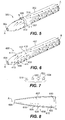
- the lateral width of the raised portion, axial length of the raised portion, and effective height, h, shown in Figs. 2 and 3 are three parameters that can be adjusted to tailor performance.
- Effective height, h is the radial distance from the probe head surface, e.g. probe head surfaces 107, 207, 307, 407 and 607, to the top surface, e.g. top surfaces 111, 211, 311, 411 and 611, of the raised portion.
- a laminar boundary layer develops along the increasing diameter of the probe head forward tip, e.g. forward tips 104, 204, 304, 404 and 604.
- a raised portion e.g. raised portions 106, 206, 306, 406 and 606
- the velocity profile of the laminar boundary layer is perturbed, at which time it is expected to transition to a turbulent state.
- a static port e.g. static ports 110, 210 310, 410 and 610.
- a method of manufacturing an air data probe includes forming a probe head, e.g. probe heads 102, 202, 302, 402 and 602, and applying a raised portion, e.g. raised portions 106, 206, 306, 406 and 606, to a surface, e.g. surfaces 107, 207, 307, 407 and 607 of the probe head aft forward tip 104.
- Applying the raised portion to the surface of the probe head can include using brazing, additive manufacturing, adhesives, or the like.
- raised portions and probe heads of similar or dissimilar materials can be used as needed on an application to application basis. It is also contemplated that a method of manufacturing the air data probe can include forming the probe head and the raised portion from a one-step machining process, for example, the air data probe and the raised portion can be formed by machining a single piece of material.
Abstract
Description
- The present invention relates to air data probes and more particularly to air data probes for aerospace applications.
- A variety of air data probe devices are known in the art for aircraft flight control. Of such devices, many are directed to measuring Pitot pressure, static pressure, local angle of attack pressures, and angle of sideslip pressures as parameters for calculating pressure altitude, altitude rate, airspeed, Mach number, angle of attack, and angle of sideslip. The air data probe typically includes one or more static pressure ports located on the side of the probe head integral to the probe's surface which sense the atmospheric pressure outside of the aircraft. When these static pressure ports take consistent pressure measurements, they can provide accurate and consistent calculations of the above mentioned parameters.
- During periods where an air data probe is at a high altitude, angle of attack, and/or Mach number, it is possible for the air data probe to have inconsistent measurement errors in the static ports. There can be considerable variations from one probe to another, suggesting there is a sensitivity to an unknown variable at the conditions described above.
- Such conventional methods and systems generally have been considered satisfactory for their intended purpose. However, there is still a need to advance the state of the art by reducing data inconsistencies in air data probes at high altitude, Mach, and/or angle of attack. The present invention provides a solution for these problems.
- An air data probe includes a probe head and a raised portion. The probe head defines a longitudinal axis and includes a forward tip and a probe head surface. The raised portion is defined in the probe head surface aft of the forward tip. The raised portion is raised radially relative to the probe head surface. The raised portion is configured and adapted to trip a fluid boundary layer passing over the probe head to transition from laminar to turbulent for reducing boundary layer separation for consistent readings at high altitudes and/or high mach numbers.
- The raised portion is defined proximate the forward tip. The air data probe can include a static port proximate the forward tip. The raised portion can be defined annularly around the probe head axially between the forward tip and the static port. The raised portion can be configured and adapted to trip a fluid boundary layer at low Reynolds numbers on the order of 105, at a speed of approximately Mach 0.9, and/or at a non-zero angle of attack.
- The raised portion can include a group of discrete raised portions, can be arranged in a strip defined along the surface of the probe head in an axial direction, and/or can be arranged in a zig-zag pattern. The zig-zag pattern can have a generally constant lengthwise geometric pattern. The raised portion can be arranged in a single strip, or opposing strips, i.e. strips on opposed radii of the probe head. The strip or strips can be defined along a surface of the probe head in an axial direction. The center of the strip or strips can be located 90 degrees from the static port. The raised portion can include sharp edged and/or curved transitions between a top surface of the raised portion and a side of the raised portion. The top surface of the raised portion can define a perimeter with a rectangle shape, a square shape, a triangle shape, a circle shape, a cross shape, a star shape, and/or any other suitable shape.
- A method of manufacturing an air data probe includes forming a probe head and applying a raised portion to a surface of the probe head aft of the forward tip. Applying the raised portion to the surface of the probe head includes using brazing, additive manufacturing, adhesives, and/or any other suitable technique.
- These and other features of the systems and methods of the subject invention will become more readily apparent to those skilled in the art from the following detailed description of the preferred embodiments taken in conjunction with the drawings.
- So that those skilled in the art to which the subject invention appertains will readily understand how to make and use the devices and methods of the subject invention without undue experimentation, exemplary embodiments thereof will be described in detail herein below by way of example only and with reference to certain figures, wherein:
-
Fig. 1 is a perspective view of an exemplary embodiment of an air data probe constructed in accordance with the present invention, showing a raised portion and a schematic depiction of the air flow over the air data probe; -
Fig. 2 is a cross-sectional view of a portion of the air data probe ofFig. 1 , showing the sharp edges of the raised portion. -
Fig. 3 is a cross-sectional view of a portion of another exemplary embodiment of an air data probe constructed in accordance with the present invention, showing the raised portion with curved edges; -
Fig. 4 is a perspective view of another exemplary embodiment of an air data probe constructed in accordance with the present invention, showing a zig-zag raised portion; -
Fig. 5 is a perspective view of another exemplary embodiment of an air data probe constructed in accordance with the present invention, showing a raised portion defined annularly around the probe head; -
Fig. 6 is a perspective view of another exemplary embodiment of an air data probe constructed in accordance with the present invention, showing a raised portion including a group of discrete raised portions having circular shaped perimeters; -
Fig. 7 is a schematic plan view of exemplary embodiments of discrete raised portions constructed in accordance with the present invention, showing the perimeters of the discrete raised portions having a triangle shape, a rectangle shape, a cross shape, and a star shape; and -
Fig. 8 is an enlarged plan view of a portion of another exemplary embodiment of an air data probe constructed in accordance with the present invention, showing hump shaped discrete raised portions. - Reference will now be made to the drawings wherein like reference numerals identify similar structural features or aspects of the subject invention. For purposes of explanation and illustration, and not limitation, a partial view of an exemplary embodiment of an air data probe in accordance with the invention is shown in
Fig. 1 and is designated generally byreference character 100. Other exemplary embodiments of air data probes in accordance with the invention, or aspects thereof, are provided inFigs. 2-8 as will be described. - As shown in
Fig. 1 , anair data probe 100 includes aprobe head 102 and a raisedportion 106.Probe head 102 defines a longitudinal axis A and includes aforward tip 104 and aprobe head surface 107.Air data probe 100 includes astatic port 110 proximateforward tip 104. Raisedportion 106 is defined inprobe head surface 107 aft offorward tip 104 and is raised radially relative toprobe head surface 107. Raisedportion 106 is configured and adapted to trip a fluid boundary layer passing overprobe head 102 to transition from laminar to turbulent for reducing and/or controlling boundary layer separation for consistent readings at low Reynolds number (Re) flight conditions, high altitudes, angle of attack and/or high Mach number. Raisedportion 106 is arranged in a strip defined alongsurface 107 ofprobe head 102 in an axial direction. In the circumferential direction, the center of raisedportion 106 is located 90 degrees fromstatic port 110. - With continued reference to
Fig. 1 , although raisedportion 106 is shown as a single strip, it will be appreciated that an opposed, e.g. circumferentially opposed, raised portion can be defined alongprobe head surface 107 on the opposite side from raisedportion 106. Whileair data probe 100 is illustrated with only onestatic port 110 and one raisedportion 106, additional static ports and raised portions can be arranged onprobe head 102 in any suitable position for a given application. - With reference now to
Fig. 2 , raisedportion 106 includes sharpedged transitions 115 between atop surface 111 of raisedportion 106 and aside 113 of raisedportion 106. Raisedportion 106 is configured and adapted to trip turbulence in a fluid boundary layer at low Re flight conditions, on the order of 105, and at a speed of approximately Mach 0.9. At angles of side slip and/or angles of attack, these conditions create a cross-flow as depicted schematically by the flow arrows inFig. 1 . The raisedportion 106 trips turbulence in the boundary layer of the flow crossing it in these conditions to reduce occurrences of boundary layer separation in the vicinity ofstatic port 110. - As shown in
Fig. 3 , raisedportion 106 optionally includescurved transitions 119 betweentop surface 111 andside 113.Curved transitions 119 can be in place of sharpedged transitions 115 or in addition to sharpedged transitions 115. It is also contemplated that raisedportion 106 can includecurved transitions 119 betweensides 113 andprobe head surface 107, similar to the cross-section having ahump shape 626, described below. Raisedportion 106 can also includecurved transitions 119 on the forward and aft ends of the strip. - Now with reference to
Fig. 4 , anair data probe 200 includes aprobe head 202, aforward tip 204, astatic port 210, and aprobe head surface 207, and is generally similarair data probe 100, described above.Air data probe 200 includes a raisedportion 206 arranged in a zig-zag pattern in an axial direction alongprobe head 202. Raisedportion 206 is similar to raisedportion 106, as described above, in that it includes sharp edgedtransitions 215 and is arranged in an axial direction. The zig-zag pattern can have a generally constant lengthwise geometric pattern, or any suitable variation thereof for a given application. It is also contemplated that raisedportion 206 can be arranged in a zig-zag pattern defined annularly aroundprobe head 202 axially betweenforward tip 204 andstatic port 210, similar to the raised portion inFig. 5 , described below. Raisedportion 206 is configured and adapted to trip turbulence as described above with respect to raisedportion 106. Whileair data probe 200 is shown with a singlestatic port 210, any suitable number of static ports can be used for a given application. - Now with reference to
Fig. 5 ,air data probe 300 is generally similar toair data probe 100 in that it includes aprobe head 302, aforward tip 304, astatic port 310, and aprobe head surface 307.Air data probe 300 includes a raisedportion 306 is defined annularly aroundprobe head 302 e.g. a ring. Raisedportion 306 is defined axially betweenforward tip 304 andstatic port 310, respectively. It is contemplated that raisedportion 306 can be at any axial position alongprobe head surface 307. Raisedportion 306 is defined in a lateral plane, wherein the lateral plane is perpendicular to longitudinal axis A. The angle of the plane in which raisedportion 306 is defined can vary as suitable for a given application. - With continued reference to
Fig. 5 , raisedportion 306 includes sharp edged transitions 315 between atop surface 311 of raisedportion 306 and aside 313 of raisedportion 306, similar to raisedportion 106, described above. In addition, raisedportion 306 has a similar width-wise cross-section to that of raisedportion 106. It is contemplated that raisedportion 306 can include curved transitions, e.g.curved transitions 119, described above with respect toFig. 3 . Raisedportion 306 is configured and adapted to trip turbulence, similar to raisedportion 106 described above. - As shown in
Fig. 6 ,air data probe 400 is generally similar toair data probe 100 in that it includes aprobe head 402, aforward tip 404, astatic port 410, and aprobe head surface 407. A raisedportion 406 is defined inprobe head 402 as a group of discrete raisedportions 405 arranged in an axially extending line. Atop surface 411 of discrete raisedportion 405 defines aperimeter 417 with a circle shape 418. Raisedportion 406 is configured and adapted to trip turbulence, similar to raisedportion 106 described above. It is contemplated that a raised portion with discrete raised portions can be defined annularly aroundprobe head 402 axially betweenforward tip 404 andstatic port 410, respectively, similar to raisedportion 306, described above. - Now with reference to
Figs. 6 and 7 ,perimeter 417 oftop surface 411 of discrete raisedportions 405 can have a variety of different shapes. For example,perimeter 417 can have a triangle shapedperimeter 518, arectangle shape perimeter 520, a cross shapedperimeter 522, a star shapedperimeter 524, and/or any other suitable perimeter. A variety of different perimeter shapes can be used depending on what is suitable for a given application. While shown and described in the exemplary context of each discrete varied portion being identical, the size and shape can be varied within the group. - As shown in
Fig. 8 , air data probe 600 is generally similar toair data probe 100 in that it includes aprobe head 602, a forward tip 604, astatic port 610, and aprobe head surface 607. A raisedportion 606 is defined inprobe head 602 as a group of discrete raisedportions 605. Raisedportion 606 is configured and adapted to trip turbulence, similar to raisedportion 106 described above. Each discrete raisedportion 605 includes a cross-section having ahump shape 626. Discrete raisedportions 605 includecurved transitions 619 between atop surface 611 of hump andsurface 607 of probe head. The other raised portions, e.g. raisedportions top surfaces sides transition 215, or in addition to the sharp edged transitions. It is also contemplated that the other raised portions can include curved transitions between their sides and the probe head surfaces, e.g. surfaces 107, 207, 307 and 407, of their respective probe heads. - Any raised portion, e.g. raised
portions shapes - By systematically varying parameters of the raised portion, e.g. raised
portions Figs. 2 and 3 , are three parameters that can be adjusted to tailor performance. Effective height, h, is the radial distance from the probe head surface, e.g. probe head surfaces 107, 207, 307, 407 and 607, to the top surface, e.g.top surfaces - With further reference to
Figs. 1-8 , as air flows over a probe head, e.g. probe heads 102, 202, 302, 402 and 602, shown schematically from left to right inFigs. 1 , and4-6 , a laminar boundary layer develops along the increasing diameter of the probe head forward tip, e.g. forwardtips portions static ports - A method of manufacturing an air data probe, e.g. air data probes 100, 200, 300, 400 and 600, includes forming a probe head, e.g. probe heads 102, 202, 302, 402 and 602, and applying a raised portion, e.g. raised
portions forward tip 104. Applying the raised portion to the surface of the probe head can include using brazing, additive manufacturing, adhesives, or the like. Moreover, raised portions and probe heads of similar or dissimilar materials can be used as needed on an application to application basis. It is also contemplated that a method of manufacturing the air data probe can include forming the probe head and the raised portion from a one-step machining process, for example, the air data probe and the raised portion can be formed by machining a single piece of material. - The methods and systems of the present invention, as described above and shown in the drawings, provide for air data probes with superior properties including reducing and/or controlling boundary layer separation for consistent readings at low Re, e.g. at high altitudes, Mach number, and/or angle of attack. While the apparatus and methods of the subject invention have been shown and described with reference to certain embodiments, those skilled in the art will readily appreciate that changes and/or modifications may be made thereto without departing from the scope of the subject invention as defined by the appended claims.
Claims (15)
- An air data probe comprising:a probe head (102;202;302;402;602), the probe head defining a longitudinal axis (A) with a forward tip (104;204;304;404;604) and a probe head surface (107;207;307;407;607); anda raised portion (106;206;306;406;606) defined in the probe head surface aft of the forward tip, wherein the raised portion is raised radially relative to the probe head surface, wherein the raised portion is configured and adapted to trip a fluid boundary layer passing over the probe head to transition from laminar to turbulent for reducing boundary layer separation for consistent readings at high altitudes and high mach numbers.
- An air data probe as recited in claim 1, wherein the raised portion (106;206;306;406;606) is defined proximate the forward tip (104;204;304;404;604).
- An air data probe as recited in claim 1 or 2, further comprising a static port (310) proximate the forward tip (304), wherein the raised portion is defined annularly around the probe head (302) axially between the forward tip and the static port.
- An air data probe as recited in claim 1,2 or 3, wherein the raised portion (106;206;306;406;606) is configured and adapted to trip a fluid boundary layer at low Reynolds numbers on the order of 105.
- An air data probe as recited in any preceding claim, wherein the raised portion (106;206;306;406;606) is configured and adapted to trip a fluid boundary layer at a speed of approximately Mach 0.9.
- An air data probe as recited in any preceding claim, wherein the raised portion (106;206;306;406;606) is configured and adapted to trip a fluid boundary layer at an angle of attack greater than or less than zero degrees.
- An air data probe as recited in any preceding claim, wherein the raised portion (406;606) includes a group of discrete raised portions (405;605).
- An air data probe as recited in claim 1 or 2, wherein the raised portion (206) is arranged in a zig-zag pattern, wherein the zig-zag pattern has a generally constant lengthwise geometric pattern.
- An air data probe as recited in claim 1 or 2, wherein the raised portion (106;206;406;606) is arranged in a strip defined along the surface (107;207;407;607) of the probe head (102;202;402;602) in an axial direction.
- An air data probe as recited in claim 1 or 2, wherein the raised portion (106;206;406;606) is arranged in opposing strips each defined along a surface (107;207;407;607) of the probe head (102;202;402;602) in an axial direction.
- An air data probe as recited in claim 1 or 2, wherein the raised portion (106;206;406;606) is arranged in a strip defined along the surface (107;207;407;607) of the probe head (102;202;402;602) in an axial direction, wherein a center of the raised portion is 90 degrees from the static port (110;210;410;610).
- An air data probe as recited in any preceding claim, further comprising sharp edged transitions (115;215) between a top surface (111 ;211 ;311 ;411) of the raised portion (106;206;306;406) and a side (113;213;313;413) of the raised portion.
- An air data probe as recited in any preceding claim, further comprising curved transitions (119;619) between a top surface (111 ;611) of the raised portion (106;606) and a side (113;613) of the raised portion.
- An air data probe as recited in any preceding claim, wherein a top surface of the raised portion defines a perimeter with a shape (518;520;522;524) selected from the group consisting of a rectangle, a triangle, a square, a circle, a cross and a star.
- A method of manufacturing an air data probe (100;200;300;400;600), the method comprising:forming a probe head (102;202;302;402;602), the probe head defining a longitudinal axis (A) with a forward tip (104;204;304;404;604) and aft base; andapplying a raised portion (106;206;306;406;606) to a surface (107;207;307;407;607) of the probe head aft of the forward tip, wherein applying the raised portion to the surface of the probe head includes using one of brazing, additive manufacturing and adhesives.
Priority Applications (1)
| Application Number | Priority Date | Filing Date | Title |
|---|---|---|---|
| EP19157942.4A EP3561520A1 (en) | 2014-05-20 | 2015-05-20 | Air data probe with means for reducing boundary layer separation |
Applications Claiming Priority (1)
| Application Number | Priority Date | Filing Date | Title |
|---|---|---|---|
| US14/282,629 US9297714B2 (en) | 2013-03-05 | 2014-05-20 | Air data probes |
Related Child Applications (1)
| Application Number | Title | Priority Date | Filing Date |
|---|---|---|---|
| EP19157942.4A Division EP3561520A1 (en) | 2014-05-20 | 2015-05-20 | Air data probe with means for reducing boundary layer separation |
Publications (2)
| Publication Number | Publication Date |
|---|---|
| EP2947465A1 true EP2947465A1 (en) | 2015-11-25 |
| EP2947465B1 EP2947465B1 (en) | 2019-02-20 |
Family
ID=53396182
Family Applications (2)
| Application Number | Title | Priority Date | Filing Date |
|---|---|---|---|
| EP15168478.4A Active EP2947465B1 (en) | 2014-05-20 | 2015-05-20 | Air data probe with means for reducing boundary layer separation |
| EP19157942.4A Withdrawn EP3561520A1 (en) | 2014-05-20 | 2015-05-20 | Air data probe with means for reducing boundary layer separation |
Family Applications After (1)
| Application Number | Title | Priority Date | Filing Date |
|---|---|---|---|
| EP19157942.4A Withdrawn EP3561520A1 (en) | 2014-05-20 | 2015-05-20 | Air data probe with means for reducing boundary layer separation |
Country Status (3)
| Country | Link |
|---|---|
| EP (2) | EP2947465B1 (en) |
| BR (1) | BR102015011343B1 (en) |
| CA (1) | CA2891064C (en) |
Cited By (2)
| Publication number | Priority date | Publication date | Assignee | Title |
|---|---|---|---|---|
| EP3179253A1 (en) * | 2015-12-10 | 2017-06-14 | Rosemount Aerospace Inc. | Air data probe with elliptical cross section |
| EP3270169A3 (en) * | 2016-07-15 | 2018-02-14 | Rosemount Aerospace Inc. | Air data probe with turbulence-producing geometry |
Families Citing this family (1)
| Publication number | Priority date | Publication date | Assignee | Title |
|---|---|---|---|---|
| CN110795869B (en) * | 2020-01-06 | 2020-04-07 | 中国人民解放军国防科技大学 | Numerical calculation method and device for flow field data |
Citations (6)
| Publication number | Priority date | Publication date | Assignee | Title |
|---|---|---|---|---|
| GB1066935A (en) * | 1965-04-07 | 1967-04-26 | British Aircraft Corp Ltd | Ringed pitot static probe |
| GB1413990A (en) * | 1972-04-19 | 1975-11-12 | Secr Defence | Static pressure sensing apparatus |
| US5313700A (en) * | 1991-01-11 | 1994-05-24 | United Technologies Corporation | Forming a flow directing element for a turbine |
| JP2006009976A (en) * | 2004-06-28 | 2006-01-12 | Ko Yamaguchi | Fluid separation reducing device |
| EP2407671A1 (en) * | 2009-03-10 | 2012-01-18 | Daikin Industries, Ltd. | Crossflow fan and air conditioner provided with same |
| GB2490170A (en) * | 2011-04-21 | 2012-10-24 | Anakata Wind Power Resources S A R L | Diffuser-augmented wind turbines |
Family Cites Families (1)
| Publication number | Priority date | Publication date | Assignee | Title |
|---|---|---|---|---|
| US9341533B2 (en) * | 2013-03-05 | 2016-05-17 | Rosemount Aerospace Inc. | Air data probes |
-
2015
- 2015-05-07 CA CA2891064A patent/CA2891064C/en active Active
- 2015-05-18 BR BR102015011343-9A patent/BR102015011343B1/en active IP Right Grant
- 2015-05-20 EP EP15168478.4A patent/EP2947465B1/en active Active
- 2015-05-20 EP EP19157942.4A patent/EP3561520A1/en not_active Withdrawn
Patent Citations (6)
| Publication number | Priority date | Publication date | Assignee | Title |
|---|---|---|---|---|
| GB1066935A (en) * | 1965-04-07 | 1967-04-26 | British Aircraft Corp Ltd | Ringed pitot static probe |
| GB1413990A (en) * | 1972-04-19 | 1975-11-12 | Secr Defence | Static pressure sensing apparatus |
| US5313700A (en) * | 1991-01-11 | 1994-05-24 | United Technologies Corporation | Forming a flow directing element for a turbine |
| JP2006009976A (en) * | 2004-06-28 | 2006-01-12 | Ko Yamaguchi | Fluid separation reducing device |
| EP2407671A1 (en) * | 2009-03-10 | 2012-01-18 | Daikin Industries, Ltd. | Crossflow fan and air conditioner provided with same |
| GB2490170A (en) * | 2011-04-21 | 2012-10-24 | Anakata Wind Power Resources S A R L | Diffuser-augmented wind turbines |
Cited By (4)
| Publication number | Priority date | Publication date | Assignee | Title |
|---|---|---|---|---|
| EP3179253A1 (en) * | 2015-12-10 | 2017-06-14 | Rosemount Aerospace Inc. | Air data probe with elliptical cross section |
| US10281353B2 (en) | 2015-12-10 | 2019-05-07 | Rosemount Aerospace Inc. | Pneumatic air data probe with elliptical cross section |
| EP3270169A3 (en) * | 2016-07-15 | 2018-02-14 | Rosemount Aerospace Inc. | Air data probe with turbulence-producing geometry |
| US10416188B2 (en) | 2016-07-15 | 2019-09-17 | Rosemount Aerospace Inc. | Air data probe with turbulence-producing geometry |
Also Published As
| Publication number | Publication date |
|---|---|
| EP3561520A1 (en) | 2019-10-30 |
| BR102015011343B1 (en) | 2021-05-18 |
| CA2891064A1 (en) | 2015-11-20 |
| CA2891064C (en) | 2023-04-18 |
| EP2947465B1 (en) | 2019-02-20 |
| BR102015011343A2 (en) | 2016-01-05 |
Similar Documents
| Publication | Publication Date | Title |
|---|---|---|
| EP2775310B1 (en) | Air data probes | |
| US9297714B2 (en) | Air data probes | |
| EP2700952B1 (en) | Moisture resistant air data probes | |
| CA2891064C (en) | Air data probes | |
| US10006813B2 (en) | Temperature sensors | |
| Tani et al. | Impingement of a round jet on a flat surface | |
| EP2848904B1 (en) | Supercritical total air temperature sensors | |
| EP3073276A2 (en) | Air data probe with improved performance when operating at a high angle of attack | |
| CA2867791A1 (en) | Total air temperature sensors | |
| EP3270169A2 (en) | Air data probe with turbulence-producing geometry | |
| US9944383B2 (en) | Pneumatic yaw control effector for aircraft | |
| EP3149494B1 (en) | Apparatus and method for assisting with fluid pressure measurement | |
| de Paula et al. | The Thickness Effect on Symmetrical Airfoil Flow Characteristics at low Reynolds number | |
| Zhang et al. | Jet direction control using circular cylinder with tangential blowing | |
| Pereira et al. | Hover Tests of Micro Aerial Vehicle‐Scale Shrouded Rotors, Part II: Flow Field Measurements | |
| EP3179253A1 (en) | Air data probe with elliptical cross section | |
| Pomeroy et al. | Pressure measurements of burst wakes over a three-element airfoil | |
| Sidnyaev | Pressure distribution along the surface of combined bodies streamlined by a hypersonic flow | |
| Ellingson et al. | A combined experimental and numerical analysis of UAV Pitot-static system error at low Reynolds number | |
| US10823752B2 (en) | Method for determining airplane flight-path angle with the use of airspeed and the global positioning system (GPS) | |
| FORCONI | Development of Kalman Filters for Navigation and Flow Angles Calibration of Air Data Systems | |
| ALBUM | Flow inclination measurements in hypersonic tunnels | |
| Seitz | Evaluation of Initial Amplitudes of Free-Stream Excited Tollmien-Schlichting Waves from Flight-Test Data | |
| Yuta et al. | 1201 PRESSURE DISTRIBUTION ON A NACA0012 AIRFOIL AT LOW REYNOLDS NUMBERS |
Legal Events
| Date | Code | Title | Description |
|---|---|---|---|
| PUAI | Public reference made under article 153(3) epc to a published international application that has entered the european phase |
Free format text: ORIGINAL CODE: 0009012 |
|
| AK | Designated contracting states |
Kind code of ref document: A1 Designated state(s): AL AT BE BG CH CY CZ DE DK EE ES FI FR GB GR HR HU IE IS IT LI LT LU LV MC MK MT NL NO PL PT RO RS SE SI SK SM TR |
|
| AX | Request for extension of the european patent |
Extension state: BA ME |
|
| 17P | Request for examination filed |
Effective date: 20160524 |
|
| RBV | Designated contracting states (corrected) |
Designated state(s): AL AT BE BG CH CY CZ DE DK EE ES FI FR GB GR HR HU IE IS IT LI LT LU LV MC MK MT NL NO PL PT RO RS SE SI SK SM TR |
|
| STAA | Information on the status of an ep patent application or granted ep patent |
Free format text: STATUS: REQUEST FOR EXAMINATION WAS MADE |
|
| R17P | Request for examination filed (corrected) |
Effective date: 20160524 |
|
| STAA | Information on the status of an ep patent application or granted ep patent |
Free format text: STATUS: EXAMINATION IS IN PROGRESS |
|
| 17Q | First examination report despatched |
Effective date: 20170531 |
|
| GRAP | Despatch of communication of intention to grant a patent |
Free format text: ORIGINAL CODE: EPIDOSNIGR1 |
|
| STAA | Information on the status of an ep patent application or granted ep patent |
Free format text: STATUS: GRANT OF PATENT IS INTENDED |
|
| RIC1 | Information provided on ipc code assigned before grant |
Ipc: G01L 15/00 20060101ALI20180726BHEP Ipc: G01P 5/165 20060101AFI20180726BHEP |
|
| INTG | Intention to grant announced |
Effective date: 20180821 |
|
| GRAS | Grant fee paid |
Free format text: ORIGINAL CODE: EPIDOSNIGR3 |
|
| GRAA | (expected) grant |
Free format text: ORIGINAL CODE: 0009210 |
|
| STAA | Information on the status of an ep patent application or granted ep patent |
Free format text: STATUS: THE PATENT HAS BEEN GRANTED |
|
| AK | Designated contracting states |
Kind code of ref document: B1 Designated state(s): AL AT BE BG CH CY CZ DE DK EE ES FI FR GB GR HR HU IE IS IT LI LT LU LV MC MK MT NL NO PL PT RO RS SE SI SK SM TR |
|
| REG | Reference to a national code |
Ref country code: GB Ref legal event code: FG4D |
|
| REG | Reference to a national code |
Ref country code: CH Ref legal event code: EP |
|
| REG | Reference to a national code |
Ref country code: DE Ref legal event code: R096 Ref document number: 602015024739 Country of ref document: DE |
|
| REG | Reference to a national code |
Ref country code: AT Ref legal event code: REF Ref document number: 1098903 Country of ref document: AT Kind code of ref document: T Effective date: 20190315 |
|
| REG | Reference to a national code |
Ref country code: IE Ref legal event code: FG4D |
|
| REG | Reference to a national code |
Ref country code: NL Ref legal event code: MP Effective date: 20190220 |
|
| REG | Reference to a national code |
Ref country code: LT Ref legal event code: MG4D |
|
| PG25 | Lapsed in a contracting state [announced via postgrant information from national office to epo] |
Ref country code: LT Free format text: LAPSE BECAUSE OF FAILURE TO SUBMIT A TRANSLATION OF THE DESCRIPTION OR TO PAY THE FEE WITHIN THE PRESCRIBED TIME-LIMIT Effective date: 20190220 Ref country code: NL Free format text: LAPSE BECAUSE OF FAILURE TO SUBMIT A TRANSLATION OF THE DESCRIPTION OR TO PAY THE FEE WITHIN THE PRESCRIBED TIME-LIMIT Effective date: 20190220 Ref country code: FI Free format text: LAPSE BECAUSE OF FAILURE TO SUBMIT A TRANSLATION OF THE DESCRIPTION OR TO PAY THE FEE WITHIN THE PRESCRIBED TIME-LIMIT Effective date: 20190220 Ref country code: SE Free format text: LAPSE BECAUSE OF FAILURE TO SUBMIT A TRANSLATION OF THE DESCRIPTION OR TO PAY THE FEE WITHIN THE PRESCRIBED TIME-LIMIT Effective date: 20190220 Ref country code: PT Free format text: LAPSE BECAUSE OF FAILURE TO SUBMIT A TRANSLATION OF THE DESCRIPTION OR TO PAY THE FEE WITHIN THE PRESCRIBED TIME-LIMIT Effective date: 20190620 Ref country code: NO Free format text: LAPSE BECAUSE OF FAILURE TO SUBMIT A TRANSLATION OF THE DESCRIPTION OR TO PAY THE FEE WITHIN THE PRESCRIBED TIME-LIMIT Effective date: 20190520 |
|
| PG25 | Lapsed in a contracting state [announced via postgrant information from national office to epo] |
Ref country code: RS Free format text: LAPSE BECAUSE OF FAILURE TO SUBMIT A TRANSLATION OF THE DESCRIPTION OR TO PAY THE FEE WITHIN THE PRESCRIBED TIME-LIMIT Effective date: 20190220 Ref country code: BG Free format text: LAPSE BECAUSE OF FAILURE TO SUBMIT A TRANSLATION OF THE DESCRIPTION OR TO PAY THE FEE WITHIN THE PRESCRIBED TIME-LIMIT Effective date: 20190520 Ref country code: LV Free format text: LAPSE BECAUSE OF FAILURE TO SUBMIT A TRANSLATION OF THE DESCRIPTION OR TO PAY THE FEE WITHIN THE PRESCRIBED TIME-LIMIT Effective date: 20190220 Ref country code: IS Free format text: LAPSE BECAUSE OF FAILURE TO SUBMIT A TRANSLATION OF THE DESCRIPTION OR TO PAY THE FEE WITHIN THE PRESCRIBED TIME-LIMIT Effective date: 20190620 Ref country code: HR Free format text: LAPSE BECAUSE OF FAILURE TO SUBMIT A TRANSLATION OF THE DESCRIPTION OR TO PAY THE FEE WITHIN THE PRESCRIBED TIME-LIMIT Effective date: 20190220 Ref country code: GR Free format text: LAPSE BECAUSE OF FAILURE TO SUBMIT A TRANSLATION OF THE DESCRIPTION OR TO PAY THE FEE WITHIN THE PRESCRIBED TIME-LIMIT Effective date: 20190521 |
|
| REG | Reference to a national code |
Ref country code: AT Ref legal event code: MK05 Ref document number: 1098903 Country of ref document: AT Kind code of ref document: T Effective date: 20190220 |
|
| PG25 | Lapsed in a contracting state [announced via postgrant information from national office to epo] |
Ref country code: SK Free format text: LAPSE BECAUSE OF FAILURE TO SUBMIT A TRANSLATION OF THE DESCRIPTION OR TO PAY THE FEE WITHIN THE PRESCRIBED TIME-LIMIT Effective date: 20190220 Ref country code: IT Free format text: LAPSE BECAUSE OF FAILURE TO SUBMIT A TRANSLATION OF THE DESCRIPTION OR TO PAY THE FEE WITHIN THE PRESCRIBED TIME-LIMIT Effective date: 20190220 Ref country code: EE Free format text: LAPSE BECAUSE OF FAILURE TO SUBMIT A TRANSLATION OF THE DESCRIPTION OR TO PAY THE FEE WITHIN THE PRESCRIBED TIME-LIMIT Effective date: 20190220 Ref country code: CZ Free format text: LAPSE BECAUSE OF FAILURE TO SUBMIT A TRANSLATION OF THE DESCRIPTION OR TO PAY THE FEE WITHIN THE PRESCRIBED TIME-LIMIT Effective date: 20190220 Ref country code: RO Free format text: LAPSE BECAUSE OF FAILURE TO SUBMIT A TRANSLATION OF THE DESCRIPTION OR TO PAY THE FEE WITHIN THE PRESCRIBED TIME-LIMIT Effective date: 20190220 Ref country code: ES Free format text: LAPSE BECAUSE OF FAILURE TO SUBMIT A TRANSLATION OF THE DESCRIPTION OR TO PAY THE FEE WITHIN THE PRESCRIBED TIME-LIMIT Effective date: 20190220 Ref country code: AL Free format text: LAPSE BECAUSE OF FAILURE TO SUBMIT A TRANSLATION OF THE DESCRIPTION OR TO PAY THE FEE WITHIN THE PRESCRIBED TIME-LIMIT Effective date: 20190220 Ref country code: DK Free format text: LAPSE BECAUSE OF FAILURE TO SUBMIT A TRANSLATION OF THE DESCRIPTION OR TO PAY THE FEE WITHIN THE PRESCRIBED TIME-LIMIT Effective date: 20190220 |
|
| REG | Reference to a national code |
Ref country code: DE Ref legal event code: R097 Ref document number: 602015024739 Country of ref document: DE |
|
| PG25 | Lapsed in a contracting state [announced via postgrant information from national office to epo] |
Ref country code: PL Free format text: LAPSE BECAUSE OF FAILURE TO SUBMIT A TRANSLATION OF THE DESCRIPTION OR TO PAY THE FEE WITHIN THE PRESCRIBED TIME-LIMIT Effective date: 20190220 Ref country code: SM Free format text: LAPSE BECAUSE OF FAILURE TO SUBMIT A TRANSLATION OF THE DESCRIPTION OR TO PAY THE FEE WITHIN THE PRESCRIBED TIME-LIMIT Effective date: 20190220 |
|
| PLBE | No opposition filed within time limit |
Free format text: ORIGINAL CODE: 0009261 |
|
| STAA | Information on the status of an ep patent application or granted ep patent |
Free format text: STATUS: NO OPPOSITION FILED WITHIN TIME LIMIT |
|
| REG | Reference to a national code |
Ref country code: CH Ref legal event code: PL |
|
| PG25 | Lapsed in a contracting state [announced via postgrant information from national office to epo] |
Ref country code: AT Free format text: LAPSE BECAUSE OF FAILURE TO SUBMIT A TRANSLATION OF THE DESCRIPTION OR TO PAY THE FEE WITHIN THE PRESCRIBED TIME-LIMIT Effective date: 20190220 |
|
| 26N | No opposition filed |
Effective date: 20191121 |
|
| PG25 | Lapsed in a contracting state [announced via postgrant information from national office to epo] |
Ref country code: LI Free format text: LAPSE BECAUSE OF NON-PAYMENT OF DUE FEES Effective date: 20190531 Ref country code: CH Free format text: LAPSE BECAUSE OF NON-PAYMENT OF DUE FEES Effective date: 20190531 Ref country code: MC Free format text: LAPSE BECAUSE OF FAILURE TO SUBMIT A TRANSLATION OF THE DESCRIPTION OR TO PAY THE FEE WITHIN THE PRESCRIBED TIME-LIMIT Effective date: 20190220 |
|
| REG | Reference to a national code |
Ref country code: BE Ref legal event code: MM Effective date: 20190531 |
|
| PG25 | Lapsed in a contracting state [announced via postgrant information from national office to epo] |
Ref country code: SI Free format text: LAPSE BECAUSE OF FAILURE TO SUBMIT A TRANSLATION OF THE DESCRIPTION OR TO PAY THE FEE WITHIN THE PRESCRIBED TIME-LIMIT Effective date: 20190220 Ref country code: LU Free format text: LAPSE BECAUSE OF NON-PAYMENT OF DUE FEES Effective date: 20190520 |
|
| PG25 | Lapsed in a contracting state [announced via postgrant information from national office to epo] |
Ref country code: TR Free format text: LAPSE BECAUSE OF FAILURE TO SUBMIT A TRANSLATION OF THE DESCRIPTION OR TO PAY THE FEE WITHIN THE PRESCRIBED TIME-LIMIT Effective date: 20190220 |
|
| PG25 | Lapsed in a contracting state [announced via postgrant information from national office to epo] |
Ref country code: IE Free format text: LAPSE BECAUSE OF NON-PAYMENT OF DUE FEES Effective date: 20190520 |
|
| PG25 | Lapsed in a contracting state [announced via postgrant information from national office to epo] |
Ref country code: BE Free format text: LAPSE BECAUSE OF NON-PAYMENT OF DUE FEES Effective date: 20190531 |
|
| PG25 | Lapsed in a contracting state [announced via postgrant information from national office to epo] |
Ref country code: CY Free format text: LAPSE BECAUSE OF FAILURE TO SUBMIT A TRANSLATION OF THE DESCRIPTION OR TO PAY THE FEE WITHIN THE PRESCRIBED TIME-LIMIT Effective date: 20190220 |
|
| PG25 | Lapsed in a contracting state [announced via postgrant information from national office to epo] |
Ref country code: MT Free format text: LAPSE BECAUSE OF FAILURE TO SUBMIT A TRANSLATION OF THE DESCRIPTION OR TO PAY THE FEE WITHIN THE PRESCRIBED TIME-LIMIT Effective date: 20190220 Ref country code: HU Free format text: LAPSE BECAUSE OF FAILURE TO SUBMIT A TRANSLATION OF THE DESCRIPTION OR TO PAY THE FEE WITHIN THE PRESCRIBED TIME-LIMIT; INVALID AB INITIO Effective date: 20150520 |
|
| PG25 | Lapsed in a contracting state [announced via postgrant information from national office to epo] |
Ref country code: MK Free format text: LAPSE BECAUSE OF FAILURE TO SUBMIT A TRANSLATION OF THE DESCRIPTION OR TO PAY THE FEE WITHIN THE PRESCRIBED TIME-LIMIT Effective date: 20190220 |
|
| PGFP | Annual fee paid to national office [announced via postgrant information from national office to epo] |
Ref country code: FR Payment date: 20230420 Year of fee payment: 9 Ref country code: DE Payment date: 20230419 Year of fee payment: 9 |
|
| PGFP | Annual fee paid to national office [announced via postgrant information from national office to epo] |
Ref country code: GB Payment date: 20230420 Year of fee payment: 9 |