EP2950250A1 - System and method for providing an optimized aircraft turnaround schedule - Google Patents
System and method for providing an optimized aircraft turnaround schedule Download PDFInfo
- Publication number
- EP2950250A1 EP2950250A1 EP15170001.0A EP15170001A EP2950250A1 EP 2950250 A1 EP2950250 A1 EP 2950250A1 EP 15170001 A EP15170001 A EP 15170001A EP 2950250 A1 EP2950250 A1 EP 2950250A1
- Authority
- EP
- European Patent Office
- Prior art keywords
- aircraft
- turnaround
- aircraft turnaround
- schedule
- activity
- Prior art date
- Legal status (The legal status is an assumption and is not a legal conclusion. Google has not performed a legal analysis and makes no representation as to the accuracy of the status listed.)
- Ceased
Links
Images


Classifications
-
- G—PHYSICS
- G06—COMPUTING; CALCULATING OR COUNTING
- G06Q—INFORMATION AND COMMUNICATION TECHNOLOGY [ICT] SPECIALLY ADAPTED FOR ADMINISTRATIVE, COMMERCIAL, FINANCIAL, MANAGERIAL OR SUPERVISORY PURPOSES; SYSTEMS OR METHODS SPECIALLY ADAPTED FOR ADMINISTRATIVE, COMMERCIAL, FINANCIAL, MANAGERIAL OR SUPERVISORY PURPOSES, NOT OTHERWISE PROVIDED FOR
- G06Q10/00—Administration; Management
- G06Q10/06—Resources, workflows, human or project management; Enterprise or organisation planning; Enterprise or organisation modelling
-
- G—PHYSICS
- G08—SIGNALLING
- G08G—TRAFFIC CONTROL SYSTEMS
- G08G5/00—Traffic control systems for aircraft, e.g. air-traffic control [ATC]
- G08G5/0095—Aspects of air-traffic control not provided for in the other subgroups of this main group
-
- G—PHYSICS
- G08—SIGNALLING
- G08G—TRAFFIC CONTROL SYSTEMS
- G08G5/00—Traffic control systems for aircraft, e.g. air-traffic control [ATC]
- G08G5/0004—Transmission of traffic-related information to or from an aircraft
- G08G5/0013—Transmission of traffic-related information to or from an aircraft with a ground station
-
- G—PHYSICS
- G08—SIGNALLING
- G08G—TRAFFIC CONTROL SYSTEMS
- G08G5/00—Traffic control systems for aircraft, e.g. air-traffic control [ATC]
- G08G5/06—Traffic control systems for aircraft, e.g. air-traffic control [ATC] for control when on the ground
Definitions
- Embodiments of the present subject matter generally relate to aircraft turnaround, and more particularly, to providing an optimized aircraft turnaround schedule.
- airlines focus on minimizing turnaround time during whole journey of an aircraft.
- existing methods may rely on data obtained from airline operators and/or ground handlers who monitor aircraft turnaround activities from touchdown to takeoff of the aircraft.
- the airlines and the ground handlers may be concerned about optimising their operations and meeting quality of service (QoS).
- Current methods provide buffers in the aircraft turnaround schedule using the data obtained based on the experience of the ground handlers and/or the airlines.
- the buffers created using this data may lead to higher aircraft turnaround times than the minimum prescribed time.
- the existing methods are airport centric methods deployed at airports and hence may not monitor aircraft turnaround time throughout the journey of the aircraft.
- a system and method for providing an optimized aircraft turnaround schedule are disclosed. According to one aspect of the present subject matter, a time taken for each aircraft turnaround activity is obtained from touchdown to takeoff of an aircraft from an aircraft on-board system by a ground station system. Further, the optimized aircraft turnaround schedule is computed based on the obtained time taken for each aircraft turnaround activity using a dynamic buffer management approach by the ground station system.
- the system includes an aircraft on-board system and a ground station system communicatively coupled to the aircraft on-board system via a communication network.
- the ground station system includes a processor and memory coupled to the processor.
- the ground station system includes an aircraft turnaround optimizer residing in the memory.
- the aircraft turnaround optimizer obtains time taken for each aircraft turnaround activity from touchdown to takeoff of the aircraft from the aircraft on-board system. Further, the aircraft turnaround optimizer computes the optimized aircraft turnaround schedule based on the obtained time taken for each aircraft turnaround activity using a dynamic buffer management approach.
- a non-transitory computer-readable storage medium for providing an optimized aircraft turnaround schedule having instructions that, when executed by a computing device causes the computing device to perform the method described above.
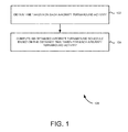
- FIG. 1 illustrates a flow diagram 100 of an exemplary method for providing an optimized aircraft turnaround schedule, according to one embodiment.
- time taken for each aircraft turnaround activity from touchdown to takeoff of an aircraft is obtained from an aircraft on-board system by a ground station system.
- aircraft turnaround activities include ground handling activities and aircraft activities.
- Exemplary ground handling activities include refueling, cargo door open, cargo door close, toilet drain cycle, portable water filling and the like.
- Exemplary aircraft activities include touchdown, braking start, brake fans start, brake fans stop, braking release, parking brake on, engine stop, aircraft arrival, aircraft docking, aircraft pull away, takeoff braking start, taxi speed reached, engine stop and the like.
- the time taken for each aircraft turnaround activity at each airport during journey of the aircraft is obtained by the ground station system. This is explained in detail with reference to FIG. 4 .
- the optimized aircraft turnaround schedule is computed based on the obtained time taken for each aircraft turnaround activity using a dynamic buffer management approach by the ground station system.
- an additional buffer time involved in each aircraft turnaround activity is determined based on the obtained time taken for each aircraft turnaround activity by the ground station system. Further, the determined additional buffer time involved in each aircraft turnaround activity is aggregated by the ground station system.
- the optimized aircraft turnaround schedule is computed by scheduling the aircraft turnaround activities along with the aggregated additional buffer time based on the time taken for each aircraft turnaround activity by the ground station system.
- the computed optimized aircraft turnaround schedule is sent to the aircraft on-board system by the ground station system.
- a consumption of the aggregated additional buffer time in the optimized aircraft turnaround schedule is dynamically determined based on the obtained time taken for each aircraft turnaround activity by the ground station system.
- the aircraft turnaround schedule is provided to one or more ground handling units by the aircraft on-board system prior to landing.
- the aircraft on-board system monitors time taken for each aircraft turnaround activity and sends the monitored time taken to the ground station system, in real-time. This is explained in detail with reference to FIG. 4 .
- the ground station system determines the consumption of the aggregated additional buffer time.
- one or more aircraft turnaround activities in the optimized aircraft turnaround schedule that consume the aggregated additional buffer time are identified by the ground station system.
- an alert is sent to one or more ground handling units associated with the one or more aircraft turnaround activities that consume the aggregated additional buffer time by the ground station system.
- the steps of dynamically determining, identifying and sending are repeated for each aircraft turnaround in the journey of the aircraft.
- the one or more aircraft turnaround activities that consume the aggregated additional buffer time are analyzed to improve process of performing the one or more aircraft turnaround activities for subsequent turnarounds of the aircraft. This is explained in detail with reference to FIGS. 2 and 3 .
- a target off-block time (TOBT) for the aircraft is estimated based on an estimated time of arrival (ETA) and the optimized aircraft turnaround schedule, prior to landing of the aircraft, by the ground station system. Furthermore, the estimated TOBT is dynamically revised based on the actual time of arrival of the aircraft and progress of the optimized aircraft turnaround schedule after arrival of the aircraft by the ground station system. Also, the airport is alerted based on the revised TOBT by the ground station system. This is explained in detail with reference to FIG. 3 .
- a passenger interface is provided to passengers of the aircraft based on the computed optimized aircraft turnaround schedule.
- the passenger interface includes a gate number, a sequence number for boarding the aircraft and a time of boarding the aircraft. This is explained in detail with reference to FIG. 6 .
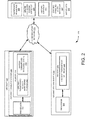
- FIG. 2 illustrates a schematic of a system 200 for providing an optimized aircraft turnaround schedule, according to one embodiment.
- the system 200 includes an aircraft 202, a ground station system 204 and interfaces 232.
- the aircraft 202 includes an aircraft on-board system 206.
- the aircraft on-board system 206 includes a processor 208 and memory 210.
- the memory 210 includes an aircraft turnaround activity monitoring module 212 and an aircraft turnaround schedule store 214.
- the ground station system 204 includes a processor 216 and memory 218. Also as shown in FIG. 2 , the memory 218 includes an aircraft turnaround optimizer 220. In addition as shown in FIG. 2 , the interfaces 232 include a passenger interface 222, an airline enterprise system interface 224, an airport interface 226 and a ground handling units interface 228.
- the ground station system 204 is coupled to the interfaces 232 and the aircraft 202 via a communication network 230.
- exemplary communication network 230 includes an Internet, an airport Wi-Fi, a mobile network, an in-flight Internet and the like.
- the aircraft turnaround activity monitoring module 212 monitors time taken for each aircraft turnaround activity from touchdown to takeoff of the aircraft 202.
- aircraft turnaround activities include ground handling activities and aircraft activities.
- Exemplary ground handling activities include refueling, cargo door open, cargo door close, toilet drain cycle, portable water filling and the like.
- Exemplary aircraft activities touchdown, braking start, brake fans start, brake fans stop, braking release, parking brake on, engine stop, aircraft arrival, aircraft docking, aircraft pull away, takeoff braking start, taxi speed reached, engine stop and the like.
- the aircraft turnaround activity monitoring module 212 monitors time taken for each aircraft turnaround activity using aircraft systems, such as aircraft condition monitoring system (ACMS), cabin intercommunication data system (CIDS) and cabin video monitoring system (CVMS) and the like.
- ACMS aircraft condition monitoring system
- CIDS cabin intercommunication data system
- CVMS cabin video monitoring system
- the aircraft turnaround optimizer 220 obtains the time taken for each aircraft turnaround activity from the aircraft turnaround activity monitoring module 212. For example, the aircraft turnaround optimizer 220 obtains the time taken for each aircraft turnaround activity at each airport during the journey of the aircraft 202 via the communication network 230. This is explained in detail with reference to FIG. 4 .
- the aircraft turnaround optimizer 220 computes the optimized aircraft turnaround schedule based on the obtained time taken for each aircraft turnaround activity using a dynamic buffer management approach.
- the aircraft turnaround optimizer 220 determines an additional buffer time involved in each aircraft turnaround activity based on the obtained time taken for each aircraft turnaround activity monitored by the aircraft on-board system 206.
- the additional buffer time is a difference between a time allotted for each aircraft turnaround activity and the time taken for each aircraft turnaround activity obtained from the aircraft on-board system 206, from touchdown to takeoff of the aircraft 202.
- the time allotted for each aircraft turnaround activity is based on inputs obtained from ground handling personals.
- the aircraft turnaround optimizer 220 aggregates the determined additional buffer time involved in each aircraft turnaround activity. Furthermore, the aircraft turnaround optimizer 220 computes the optimized aircraft turnaround schedule by scheduling the aircraft turnaround activities along with the aggregated additional buffer time based on the time taken for each aircraft turnaround activity.
- the aircraft turnaround optimizer 220 sends the computed optimized aircraft turnaround schedule to the aircraft turnaround schedule store 214.
- the aircraft turnaround optimizer 220 dynamically determines a consumption of the aggregated additional buffer time in the optimized aircraft turnaround schedule based on the obtained time taken for each aircraft turnaround activity.
- the aircraft turnaround schedule is provided to one or more ground handling units by the aircraft on-board system 206 prior to landing.
- the aircraft on-board system 206 monitors time taken for each aircraft turnaround activity and sends the monitored time taken to the ground station system 204, in real-time. Based on the obtained time taken, the ground station system 204 determines the consumption of the aggregated additional buffer time.
- the aircraft turnaround optimizer 220 identifies one or more aircraft turnaround activities in the optimized aircraft turnaround schedule that consume the aggregated additional buffer time. Also, the aircraft turnaround optimizer 220 sends alerts to one or more ground handling units associated with the one or more aircraft turnaround activities that consume the aggregated additional buffer time. For example, aircraft turnaround optimizer 220 sends alerts to one or more ground handling units associated with the one or more aircraft turnaround activities via the ground handling units interface 228. Moreover in this embodiment, the aircraft turnaround optimizer 220 repeats the steps of dynamically determining the consumption of the aggregated additional buffer time, identifying one or more aircraft turnaround activities and sending the alerts for each aircraft turnaround in the journey of the aircraft. Also, the aircraft turnaround optimizer 220 analyzes the one or more aircraft turnaround activities that consume the aggregated additional buffer time to improve process of performing the one or more aircraft turnaround activities for subsequent turnarounds of the aircraft. This is explained in detail with reference to FIG. 3 .
- the aircraft turnaround optimizer 220 estimates a TOBT for the aircraft 202 based on the optimized aircraft turnaround schedule.
- the TOBT is the time when the aircraft 202 will be ready for takeoff upon receiving clearance from the airport. This is explained in detail with reference to FIG. 3 .
- the aircraft on-board system 206 prior to landing of the aircraft 202, provides the optimized aircraft turnaround schedule to one or more ground handling units via the ground handling units interface 228.
- Exemplary ground handling units interface 228 include a display of a computing system.
- the aircraft on-board system 206 sends alerts to the one or more ground handling units based on the progress of the aircraft turnaround schedule. This is explained in detail with reference to FIG. 3 .
- the aircraft turnaround optimizer 220 provides the passenger interface 222 to the passengers of the aircraft 202 based on the computed optimized aircraft turnaround schedule.
- the passenger interface 222 includes a gate number, a sequence number for boarding the aircraft and a time of boarding the aircraft are provided to passengers of the aircraft.
- the passenger interface 222 is displayed to the passengers on a mobile device, computing device and/or an aircraft lounge display. This is explained in detail with reference to FIG. 6 .
- the aircraft turnaround optimizer 220 analyzes the time taken for each aircraft turnaround activity to measure performance of ground handling activities, performance of aircraft crew, phase of ground handling units and so on. Further, the aircraft turnaround optimizer 220 sends the analyzed data to the airline enterprise system interface 224 and the airport interface 226. This is explained in detail with reference to FIG. 3 .
- an article comprising a non-transitory computer readable storage medium having instructions thereon which when executed by a computing platform result in execution of the above mentioned method.
- the method described in the foregoing may be in a form of a machine-readable medium embodying a set of instructions that, when executed by a machine, causes the machine to perform any method disclosed herein. It will be appreciated that the various embodiments discussed herein may not be the same embodiment, and may be grouped into various other embodiments not explicitly disclosed herein.
- Each of the aircraft turnaround activity monitoring module 212 and the aircraft turnaround optimizer 220 represent any combination of circuitry and executable instructions to perform the above described systems and methods.
- the functional architecture 300 includes stored data 302, real-time data 304, aircraft turnaround optimizer systems 306 and aircraft turnaround optimizer services 308.
- the stored data 302 includes airport data 316 and ground handling data 318.
- the real-time data 304 includes aircraft on-board data 320, landing/ takeoff conditions 322, air traffic controller (ATC) conditions 324, ground handling data 326 and passenger information 328.
- ATC air traffic controller
- the aircraft turnaround optimizer systems 306 include a data analytics and machine learning module 330, an event management and alerts module 332 and a workflows module 334.
- the aircraft turnaround optimizer services 308 include dynamic aircraft turnaround activities scheduler 336, an aircraft turnaround performance management module 338, a predictive intelligence and risk management module 340, an alerts/action triggers to stakeholders module 342 and a TOBT calculation and tracking module 344.
- an airport 310 and ground handling units 312 are communicatively coupled to the airport data 316 and the ground handling data 318, respectively.
- the aircraft 202, the ground handling units 312 and an airline enterprise system 314 are communicatively coupled to the aircraft on-board data 320, the ground handling data 326 and the passenger information 328, respectively.
- the airport 310 is communicatively coupled to the landing/ takeoff conditions 322 and the ATC conditions 324.
- Exemplary communication network 230 includes Internet, an airport Wi-Fi, a mobile network, in-flight Internet and the like.
- the airport data 316 includes a terminal number, a gate number, an exit gate number and so on obtained from the airport 310.
- the ground handling data 318 includes type of ground handling units, number of ground handling units and so on obtained from ground handling units 312.
- the landing/ takeoff conditions 322 include weather, runway conditions and so on obtained from the airport 310.
- the ATC conditions 324 includes available slots, allocated gates and so on obtained the airport 310.
- the ground handling data 326 includes schedule, available ground handling units and so on obtained from the ground handling units 312.
- the passenger information 328 includes number of passengers, baggage weight, special cases and so on obtained from the airline enterprise system 314.
- the aircraft on-board data 320 obtained from the aircraft 202 includes time taken for aircraft turnaround activities, such as touchdown, braking start, taxi speed reached, brake fans start, brake fans stop, braking release, parking brake on, APU start/GPU connect, engine stop, skybridge/ ladder connect, passenger doors open, first passenger de-boarding (obtained from cabin video feed), last passenger de-boarding (obtained from cabin video feed), cleaning finish, first passenger boarding (obtained from cabin video feed), last passenger boarding (obtained from cabin video feed), passenger door closed, forward cargo door open, rear end cargo door open, forward cargo door close, rear end cargo door close, refueling start, refueling stop, catering door open, catering door closed, portable water filling start, portable water filling stop, toilet drain cycle start, toilet drain cycle stop, maintenance activity start, maintenance activity stop, parking brake release, engine start, APU/GPU stop, pushback start, brake fans start, brake fans stop, temporary stops during taxi, brake on, throttle takeoff setting and the like.
- the data analytics and machine learning module 330 determines the additional buffer time involved in each aircraft turnaround activity based on the time taken for each aircraft turnaround activity monitored by the aircraft on-board system 206. Further, the data analytics and machine learning module 330 aggregates the determined additional buffer time involved in each aircraft turnaround activity. Furthermore, the dynamic aircraft turnaround activities scheduler 336 computes the optimized aircraft turnaround schedule by scheduling the aircraft turnaround activities along with the aggregated additional buffer time based on the time taken for each aircraft turnaround activity. In addition, the workflows module 334 sends alerts to the ground handling units 312 based on the optimized aircraft turnaround schedule. For example, based on the optimized aircraft turnaround schedule, the workflows module 334 sends a start time of each aircraft turnaround activity to associated ground handling units.
- the dynamic aircraft turnaround activities scheduler 336 sends the computed optimized aircraft turnaround schedule to the aircraft turnaround schedule store 214.
- the event management and alerts module 332 dynamically determines a consumption of the aggregated additional buffer time in the optimized aircraft turnaround schedule based on the obtained time taken for each aircraft turnaround activity.
- an aircraft turnaround activity consumes the aggregated additional buffer time when the aircraft turnaround activity gets delayed or consumes more time than a minimum prescribed time.
- the aircraft turnaround schedule is provided to one or more ground handling units by the aircraft on-board system 206 prior to landing. Further, the aircraft on-board system 206 monitors time taken for each aircraft turnaround activity and sends the monitored time taken to the ground station system 204, in real-time. Based on the obtained time taken, the event management and alerts module 332 determines the consumption of the aggregated additional buffer time.
- the event management and alerts module 332 identifies the one or more aircraft turnaround activities in the aircraft turnaround schedule that consume the aggregated additional buffer time.
- the event management and alerts module 332 sends alerts to one or more ground handling units associated with the one or more aircraft turnaround activities that consume the aggregated additional buffer time.
- the event management and alerts module 332 analyzes the one or more aircraft turnaround activities that consume the aggregated additional buffer time to improve process of performing the one or more aircraft turnaround activities for subsequent turnarounds of the aircraft. For example, the one or more ground handling units 312 may improve the process of performing the aircraft turnaround activity based on the consumption of the aggregated additional buffer time.
- the aircraft turnaround performance management module 338 measures performance of the ground handling activities, the performance of aircraft crew, the phase of ground handling units and so on. Furthermore, the aircraft turnaround performance management module 338 represents the analyzed data in the form of graphs, charts and the like. Also, the aircraft turnaround performance management module 338 sends the graphs, charts and the like to the airline enterprise system 314 and the airport 310. For example, the airline enterprise system 314 may use the analyzed data to determine taxi-in performance of the aircraft 202 in the airport 310.
- the predictive intelligence and risk management module 340 analyzes the effect of any delays caused by one or more aircraft turnaround activities on the aircraft turnaround schedule. Based on the analysis, the alerts/action triggers to stakeholders module 342 sends alerts to the passengers of the aircraft 202. This is explained in detail with reference to FIG. 6 .
- the TOBT calculation and tracking module 344 estimates a TOBT for the aircraft 202 based on the ETA of the aircraft 202 and the optimized aircraft turnaround schedule. For example, the ETA of the aircraft is obtained from the aircraft 202. Further, the TOBT calculation and tracking module 344 dynamically revises the estimated TOBT for the aircraft based on the actual time of arrival of the aircraft and the progress of the optimized aircraft turnaround schedule after arrival of the aircraft 202. For example, if the ETA of the aircraft changes more than a predefined minimum time or if a delay is predicted in the aircraft turnaround schedule, then the ETA is revised based on the change. Furthermore, the TOBT calculation and tracking module 344 alerts the airport 310 based on the revised TOBT using the event management and alerts module 332.
- the airport 310 uses the estimated TOBT for gate allocation and departure planning of the aircraft 202. If the estimated TOBT is revised due to delay in the aircraft turnaround schedule, the TOBT calculation and tracking module 344 alerts the associated ground handling units based on the delay. Upon receiving the alert, the associated ground handling units may attempt to recover the delay. Further, the airline enterprise system 314 uses the revised TOBT to coordinate airline crew activities and airline operations. Furthermore, the airport 310 uses the revised TOBT for revising the gate allocation and departure planning for the aircraft 202.
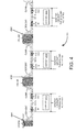
- FIG. 4 illustrates a schematic 400 illustrating an aircraft centric view of journey of the aircraft 202, according to one embodiment.
- the schematic 400 illustrates the journey of the aircraft 202 through airports 402A- 402C. Further, the schematic 400 illustrates different phases of the aircraft 202, such as cruise, descent, taxi-in, at gate, taxi-out and climb phases of the aircraft 202 at the each of the airports 402A- 402C. Furthermore, 4040A- 404C indicate locations in the journey of the aircraft 202 when the aircraft 202 sends the optimized aircraft turnaround schedule to one or more ground handling units associated with the airports 402A- 402C, respectively.
- the aircraft 202 prior to landing of the aircraft 202, at location 404A, the aircraft 202 sends the optimized aircraft turnaround schedule to one or more ground handling units in the airport 402A.
- the optimized aircraft turnaround schedule may be sent 30 minutes prior to landing of the aircraft 202.
- the optimized aircraft turnaround schedule is computed by the aircraft turnaround optimizer 220, shown in FIG. 2 , based on the historical data monitored by the aircraft 202.
- the aircraft 202 After arrival of the aircraft 202 in the airport 402A, the aircraft 202 monitors the time taken for each aircraft turnaround activity and sends the monitored data to the aircraft turnaround optimizer 220 in real-time. The aircraft turnaround optimizer 220 then updates the aircraft turnaround schedule based on the monitored time taken for each aircraft turnaround activity at the airport 402A.
- the aircraft 202 monitors the time taken for each aircraft turnaround activity. Further, the aircraft turnaround optimizer 220 updates the aircraft turnaround schedule based on the monitored time taken for each aircraft turnaround activity at each of the airport 402A- 402C. Furthermore, the aircraft turnaround optimizer 220 determines a consumption of the aggregated buffer time, identifies the one or more aircraft turnaround activities consuming the aggregated buffer time and sends alerts to one or more ground handling units associated with the identified one or more aircraft turnaround activities at each of the airports 402A- 402C.
- FIG. 5 illustrates a schematic illustrating exemplary aircraft turnaround activities scheduled from touchdown to takeoff of the aircraft 202, according to one embodiment.
- the aircraft turnaround activities include an aircraft descent 502, landing 504, taxi 506, docking 508, de-boarding 510, catering and cleaning 512, boarding 514, refueling 516, cargo unloading 518, cargo loading 520, sanitation and portable water 522, release of aircraft 524, push back 526 and takeoff 528.
- the aircraft turnaround activities such as landing 504, taxi 506 and docking 508 are scheduled in series after the aircraft descent 502.
- the aircraft turnaround activities such as de-boarding 510, cargo unloading 518, and sanitation and portable water 522 are scheduled in parallel.
- the de-boarding 510, the cargo unloading 518, and the sanitation and portable water 522 are performed by different ground handling units and hence may be performed in parallel.
- the refueling 516 is performed after the de-boarding 510 is completed.
- the aircraft turnaround activities such as catering and cleaning 512 and boarding 514 are scheduled in series after de-boarding 510.
- FIG. 5 the aircraft turnaround activities, such as catering and cleaning 512 and boarding 514 are scheduled in series after de-boarding 510.
- cargo loading 520 is scheduled after cargo unloading 518.
- the release of the aircraft 524 is scheduled.
- the push back 526 and take off 528 are scheduled.
- all other aircraft turnaround activities are scheduled based on the time taken for each aircraft turnaround activity, ground handling units used for performing the aircraft turnaround activity and availability of ground handling units to perform the aircraft turnaround activity.
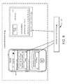
- FIG. 6 is a schematic 600 illustrating the passenger interface 222 for providing alerts to passengers of the aircraft 202, according to one embodiment.
- the schematic 600 includes the passenger interface 222 and the ground station system 204.
- the passenger interface 222 includes a mobile phone 602 and an airport lounge display 604.
- the ground station system 204 is communicatively coupled to the passenger interface 222.
- the ground station system 204 provides the passenger interface 222 to the passengers of the aircraft 202 based on the computed optimized aircraft turnaround schedule.
- the passenger interface 222 includes a gate number, a sequence number for boarding the aircraft and a time for boarding the aircraft to the passengers of the aircraft. For example, based on historical data of an aircraft and an airport, the ground station system 204 computes a rate of boarding the passengers of the aircraft. Based on the rate of boarding the passengers computed and the progress of the aircraft turnaround activities, the ground station system 204 computes a time of boarding the passengers for each sequence number.
- the ground station system 204 sends an alert to the mobile phone 602 including a flight number, a gate number, a seat number, a boarding sequence number and a boarding start time. For example, the ground station system 204 sends an alert to the mobile phone 602 via an SMS, an e-mail or a notification. Further, after the boarding starts, the ground station system 204 sends another alert to the mobile phone 602 including a time for joining the boarding queue. Furthermore as shown in FIG. 6 , the ground station system 204 also sends an alert to the airport lounge display 604 including the flight number, an airline logo, sequence numbers and seat numbers of passengers boarding the aircraft.
- the various devices, modules, analyzers, generators, and the like described herein may be enabled and operated using hardware circuitry, for example, complementary metal oxide semiconductor based logic circuitry, firmware, software and/or any combination of hardware, firmware, and/or software embodied in a machine readable medium.
- the various electrical structure and methods may be embodied using transistors, logic gates, and electrical circuits, such as application specific integrated circuit.
Abstract
Description
- Embodiments of the present subject matter generally relate to aircraft turnaround, and more particularly, to providing an optimized aircraft turnaround schedule.
- Typically, airlines focus on minimizing turnaround time during whole journey of an aircraft. In order to minimize the aircraft turnaround time, existing methods may rely on data obtained from airline operators and/or ground handlers who monitor aircraft turnaround activities from touchdown to takeoff of the aircraft. The airlines and the ground handlers may be concerned about optimising their operations and meeting quality of service (QoS). Current methods provide buffers in the aircraft turnaround schedule using the data obtained based on the experience of the ground handlers and/or the airlines. However, the buffers created using this data may lead to higher aircraft turnaround times than the minimum prescribed time. Further, the existing methods are airport centric methods deployed at airports and hence may not monitor aircraft turnaround time throughout the journey of the aircraft.
- A system and method for providing an optimized aircraft turnaround schedule are disclosed. According to one aspect of the present subject matter, a time taken for each aircraft turnaround activity is obtained from touchdown to takeoff of an aircraft from an aircraft on-board system by a ground station system. Further, the optimized aircraft turnaround schedule is computed based on the obtained time taken for each aircraft turnaround activity using a dynamic buffer management approach by the ground station system.
- According to another aspect of the present subject matter, the system includes an aircraft on-board system and a ground station system communicatively coupled to the aircraft on-board system via a communication network. Further, the ground station system includes a processor and memory coupled to the processor. Furthermore, the ground station system includes an aircraft turnaround optimizer residing in the memory. In one embodiment, the aircraft turnaround optimizer obtains time taken for each aircraft turnaround activity from touchdown to takeoff of the aircraft from the aircraft on-board system. Further, the aircraft turnaround optimizer computes the optimized aircraft turnaround schedule based on the obtained time taken for each aircraft turnaround activity using a dynamic buffer management approach.
- According to yet another aspect of the present subject matter, a non-transitory computer-readable storage medium for providing an optimized aircraft turnaround schedule, having instructions that, when executed by a computing device causes the computing device to perform the method described above.
- The system and method disclosed herein may be implemented in any means for achieving various aspects. Other features will be apparent from the accompanying drawings and from the detailed description that follow.
- Various embodiments are described herein with reference to the drawings, wherein:
-
FIG. 1 illustrates a flow diagram of an exemplary method for providing an optimized aircraft turnaround schedule, according to one embodiment; -
FIG. 2 illustrates a schematic of a system for providing the optimized aircraft turnaround schedule, according to one embodiment; -
FIG. 3 illustrates a functional architecture of an aircraft turnaround optimizer in a ground station system for providing the optimized aircraft turnaround schedule, using the method described with reference toFIG. 1 , according to one embodiment; -
FIG. 4 illustrates a schematic illustrating an aircraft centric view of journey of an aircraft, according to one embodiment; -
FIG. 5 illustrates a schematic of exemplary aircraft turnaround activities scheduled from touchdown to takeoff of the aircraft, according to one embodiment; and -
FIG. 6 illustrates a passenger interface for providing alerts to passengers of the aircraft, according to one embodiment. - The drawings described herein are for illustration purposes only and are not intended to limit the scope of the present disclosure in any way.
- A system and method for providing an optimized aircraft turnaround schedule are disclosed. In the following detailed description of the embodiments of the present subject matter, references are made to the accompanying drawings that form a part hereof, and in which are shown by way of illustration specific embodiments in which the present subject matter may be practiced. These embodiments are described in sufficient detail to enable those skilled in the art to practice the present subject matter, and it is to be understood that other embodiments may be utilized and that changes may be made without departing from the scope of the present subject matter. The following detailed description is, therefore, not to be taken in a limiting sense, and the scope of the present subject matter is defined by the appended claims.
-
FIG. 1 illustrates a flow diagram 100 of an exemplary method for providing an optimized aircraft turnaround schedule, according to one embodiment. Atstep 102, time taken for each aircraft turnaround activity from touchdown to takeoff of an aircraft is obtained from an aircraft on-board system by a ground station system. For example, aircraft turnaround activities include ground handling activities and aircraft activities. Exemplary ground handling activities include refueling, cargo door open, cargo door close, toilet drain cycle, portable water filling and the like. Exemplary aircraft activities include touchdown, braking start, brake fans start, brake fans stop, braking release, parking brake on, engine stop, aircraft arrival, aircraft docking, aircraft pull away, takeoff braking start, taxi speed reached, engine stop and the like. In one embodiment, the time taken for each aircraft turnaround activity at each airport during journey of the aircraft is obtained by the ground station system. This is explained in detail with reference toFIG. 4 . - At
step 104, the optimized aircraft turnaround schedule is computed based on the obtained time taken for each aircraft turnaround activity using a dynamic buffer management approach by the ground station system. In one embodiment, an additional buffer time involved in each aircraft turnaround activity is determined based on the obtained time taken for each aircraft turnaround activity by the ground station system. Further, the determined additional buffer time involved in each aircraft turnaround activity is aggregated by the ground station system. Furthermore, the optimized aircraft turnaround schedule is computed by scheduling the aircraft turnaround activities along with the aggregated additional buffer time based on the time taken for each aircraft turnaround activity by the ground station system. - Further in this embodiment, the computed optimized aircraft turnaround schedule is sent to the aircraft on-board system by the ground station system. Furthermore, a consumption of the aggregated additional buffer time in the optimized aircraft turnaround schedule is dynamically determined based on the obtained time taken for each aircraft turnaround activity by the ground station system. For example, the aircraft turnaround schedule is provided to one or more ground handling units by the aircraft on-board system prior to landing. Further, the aircraft on-board system monitors time taken for each aircraft turnaround activity and sends the monitored time taken to the ground station system, in real-time. This is explained in detail with reference to
FIG. 4 . Based on the obtained time taken, the ground station system determines the consumption of the aggregated additional buffer time. - In addition, one or more aircraft turnaround activities in the optimized aircraft turnaround schedule that consume the aggregated additional buffer time are identified by the ground station system. Moreover, an alert is sent to one or more ground handling units associated with the one or more aircraft turnaround activities that consume the aggregated additional buffer time by the ground station system. Also, the steps of dynamically determining, identifying and sending are repeated for each aircraft turnaround in the journey of the aircraft. In addition, the one or more aircraft turnaround activities that consume the aggregated additional buffer time are analyzed to improve process of performing the one or more aircraft turnaround activities for subsequent turnarounds of the aircraft. This is explained in detail with reference to
FIGS. 2 and3 . - Further, a target off-block time (TOBT) for the aircraft is estimated based on an estimated time of arrival (ETA) and the optimized aircraft turnaround schedule, prior to landing of the aircraft, by the ground station system. Furthermore, the estimated TOBT is dynamically revised based on the actual time of arrival of the aircraft and progress of the optimized aircraft turnaround schedule after arrival of the aircraft by the ground station system. Also, the airport is alerted based on the revised TOBT by the ground station system. This is explained in detail with reference to
FIG. 3 . - In one example, a passenger interface is provided to passengers of the aircraft based on the computed optimized aircraft turnaround schedule. The passenger interface includes a gate number, a sequence number for boarding the aircraft and a time of boarding the aircraft. This is explained in detail with reference to
FIG. 6 . - Referring now to
FIG. 2 , which illustrates a schematic of asystem 200 for providing an optimized aircraft turnaround schedule, according to one embodiment. As shown inFIG. 2 , thesystem 200 includes anaircraft 202, aground station system 204 and interfaces 232. Further as shown inFIG. 2 , theaircraft 202 includes an aircraft on-board system 206. Furthermore as shown inFIG. 2 , the aircraft on-board system 206 includes aprocessor 208 andmemory 210. In addition as shown inFIG. 2 , thememory 210 includes an aircraft turnaroundactivity monitoring module 212 and an aircraftturnaround schedule store 214. - Moreover as shown in
FIG. 2 , theground station system 204 includes aprocessor 216 andmemory 218. Also as shown inFIG. 2 , thememory 218 includes anaircraft turnaround optimizer 220. In addition as shown inFIG. 2 , theinterfaces 232 include apassenger interface 222, an airlineenterprise system interface 224, anairport interface 226 and a ground handling units interface 228. - Further as shown in
FIG. 2 , theground station system 204 is coupled to theinterfaces 232 and theaircraft 202 via acommunication network 230.Exemplary communication network 230 includes an Internet, an airport Wi-Fi, a mobile network, an in-flight Internet and the like. - In operation, the aircraft turnaround
activity monitoring module 212 monitors time taken for each aircraft turnaround activity from touchdown to takeoff of theaircraft 202. For example, aircraft turnaround activities include ground handling activities and aircraft activities. Exemplary ground handling activities include refueling, cargo door open, cargo door close, toilet drain cycle, portable water filling and the like. Exemplary aircraft activities touchdown, braking start, brake fans start, brake fans stop, braking release, parking brake on, engine stop, aircraft arrival, aircraft docking, aircraft pull away, takeoff braking start, taxi speed reached, engine stop and the like. In one example, the aircraft turnaroundactivity monitoring module 212 monitors time taken for each aircraft turnaround activity using aircraft systems, such as aircraft condition monitoring system (ACMS), cabin intercommunication data system (CIDS) and cabin video monitoring system (CVMS) and the like. - In one embodiment, the
aircraft turnaround optimizer 220 obtains the time taken for each aircraft turnaround activity from the aircraft turnaroundactivity monitoring module 212. For example, theaircraft turnaround optimizer 220 obtains the time taken for each aircraft turnaround activity at each airport during the journey of theaircraft 202 via thecommunication network 230. This is explained in detail with reference toFIG. 4 . - Further in this embodiment, the
aircraft turnaround optimizer 220 computes the optimized aircraft turnaround schedule based on the obtained time taken for each aircraft turnaround activity using a dynamic buffer management approach. In the dynamic buffer management approach, theaircraft turnaround optimizer 220 determines an additional buffer time involved in each aircraft turnaround activity based on the obtained time taken for each aircraft turnaround activity monitored by the aircraft on-board system 206. For example, the additional buffer time is a difference between a time allotted for each aircraft turnaround activity and the time taken for each aircraft turnaround activity obtained from the aircraft on-board system 206, from touchdown to takeoff of theaircraft 202. The time allotted for each aircraft turnaround activity is based on inputs obtained from ground handling personals. - Further, the
aircraft turnaround optimizer 220 aggregates the determined additional buffer time involved in each aircraft turnaround activity. Furthermore, theaircraft turnaround optimizer 220 computes the optimized aircraft turnaround schedule by scheduling the aircraft turnaround activities along with the aggregated additional buffer time based on the time taken for each aircraft turnaround activity. - Furthermore in this embodiment, the
aircraft turnaround optimizer 220 sends the computed optimized aircraft turnaround schedule to the aircraftturnaround schedule store 214. After landing of theaircraft 202, theaircraft turnaround optimizer 220 dynamically determines a consumption of the aggregated additional buffer time in the optimized aircraft turnaround schedule based on the obtained time taken for each aircraft turnaround activity. For example, the aircraft turnaround schedule is provided to one or more ground handling units by the aircraft on-board system 206 prior to landing. Further, the aircraft on-board system 206 monitors time taken for each aircraft turnaround activity and sends the monitored time taken to theground station system 204, in real-time. Based on the obtained time taken, theground station system 204 determines the consumption of the aggregated additional buffer time. - In addition in this embodiment, the
aircraft turnaround optimizer 220 identifies one or more aircraft turnaround activities in the optimized aircraft turnaround schedule that consume the aggregated additional buffer time. Also, theaircraft turnaround optimizer 220 sends alerts to one or more ground handling units associated with the one or more aircraft turnaround activities that consume the aggregated additional buffer time. For example,aircraft turnaround optimizer 220 sends alerts to one or more ground handling units associated with the one or more aircraft turnaround activities via the ground handling units interface 228. Moreover in this embodiment, theaircraft turnaround optimizer 220 repeats the steps of dynamically determining the consumption of the aggregated additional buffer time, identifying one or more aircraft turnaround activities and sending the alerts for each aircraft turnaround in the journey of the aircraft. Also, theaircraft turnaround optimizer 220 analyzes the one or more aircraft turnaround activities that consume the aggregated additional buffer time to improve process of performing the one or more aircraft turnaround activities for subsequent turnarounds of the aircraft. This is explained in detail with reference toFIG. 3 . - Also in this embodiment, the
aircraft turnaround optimizer 220 estimates a TOBT for theaircraft 202 based on the optimized aircraft turnaround schedule. The TOBT is the time when theaircraft 202 will be ready for takeoff upon receiving clearance from the airport. This is explained in detail with reference toFIG. 3 . - In one example, prior to landing of the
aircraft 202, the aircraft on-board system 206 provides the optimized aircraft turnaround schedule to one or more ground handling units via the ground handling units interface 228. Exemplary ground handling units interface 228 include a display of a computing system. Further, the aircraft on-board system 206 sends alerts to the one or more ground handling units based on the progress of the aircraft turnaround schedule. This is explained in detail with reference toFIG. 3 . - In another example, the
aircraft turnaround optimizer 220 provides thepassenger interface 222 to the passengers of theaircraft 202 based on the computed optimized aircraft turnaround schedule. Thepassenger interface 222 includes a gate number, a sequence number for boarding the aircraft and a time of boarding the aircraft are provided to passengers of the aircraft. For example, thepassenger interface 222 is displayed to the passengers on a mobile device, computing device and/or an aircraft lounge display. This is explained in detail with reference toFIG. 6 . - In yet another example, the
aircraft turnaround optimizer 220 analyzes the time taken for each aircraft turnaround activity to measure performance of ground handling activities, performance of aircraft crew, phase of ground handling units and so on. Further, theaircraft turnaround optimizer 220 sends the analyzed data to the airlineenterprise system interface 224 and theairport interface 226. This is explained in detail with reference toFIG. 3 . - In one embodiment, an article comprising a non-transitory computer readable storage medium having instructions thereon which when executed by a computing platform result in execution of the above mentioned method. The method described in the foregoing may be in a form of a machine-readable medium embodying a set of instructions that, when executed by a machine, causes the machine to perform any method disclosed herein. It will be appreciated that the various embodiments discussed herein may not be the same embodiment, and may be grouped into various other embodiments not explicitly disclosed herein. Each of the aircraft turnaround
activity monitoring module 212 and theaircraft turnaround optimizer 220 represent any combination of circuitry and executable instructions to perform the above described systems and methods. - Referring now to
FIG. 3 , which illustrates afunctional architecture 300 of theaircraft turnaround optimizer 220 in theground station system 204 for providing the optimized aircraft turnaround schedule, using the method described with reference toFIG. 1 , according to one embodiment. As shown inFIG. 3 , thefunctional architecture 300 includes storeddata 302, real-time data 304, aircraftturnaround optimizer systems 306 and aircraft turnaround optimizer services 308. Further as shown inFIG. 3 , the storeddata 302 includesairport data 316 andground handling data 318. Furthermore as shown inFIG. 3 , the real-time data 304 includes aircraft on-board data 320, landing/takeoff conditions 322, air traffic controller (ATC)conditions 324,ground handling data 326 andpassenger information 328. - In addition as shown in
FIG. 3 , the aircraftturnaround optimizer systems 306 include a data analytics andmachine learning module 330, an event management andalerts module 332 and aworkflows module 334. Moreover as shown inFIG. 3 , the aircraftturnaround optimizer services 308 include dynamic aircraft turnaround activities scheduler 336, an aircraft turnaroundperformance management module 338, a predictive intelligence andrisk management module 340, an alerts/action triggers tostakeholders module 342 and a TOBT calculation andtracking module 344. - Also as shown in
FIG. 3 , anairport 310 andground handling units 312 are communicatively coupled to theairport data 316 and theground handling data 318, respectively. Moreover as shown inFIG. 3 , theaircraft 202, theground handling units 312 and anairline enterprise system 314 are communicatively coupled to the aircraft on-board data 320, theground handling data 326 and thepassenger information 328, respectively. Further as shown inFIG. 3 , theairport 310 is communicatively coupled to the landing/takeoff conditions 322 and the ATC conditions 324.Exemplary communication network 230 includes Internet, an airport Wi-Fi, a mobile network, in-flight Internet and the like. - In one example, the
airport data 316 includes a terminal number, a gate number, an exit gate number and so on obtained from theairport 310. Further, theground handling data 318 includes type of ground handling units, number of ground handling units and so on obtained fromground handling units 312. Furthermore, the landing/takeoff conditions 322 include weather, runway conditions and so on obtained from theairport 310. In addition, theATC conditions 324 includes available slots, allocated gates and so on obtained theairport 310. Also, theground handling data 326 includes schedule, available ground handling units and so on obtained from theground handling units 312. Moreover, thepassenger information 328 includes number of passengers, baggage weight, special cases and so on obtained from theairline enterprise system 314. - Further in this example, the aircraft on-
board data 320 obtained from theaircraft 202 includes time taken for aircraft turnaround activities, such as touchdown, braking start, taxi speed reached, brake fans start, brake fans stop, braking release, parking brake on, APU start/GPU connect, engine stop, skybridge/ ladder connect, passenger doors open, first passenger de-boarding (obtained from cabin video feed), last passenger de-boarding (obtained from cabin video feed), cleaning finish, first passenger boarding (obtained from cabin video feed), last passenger boarding (obtained from cabin video feed), passenger door closed, forward cargo door open, rear end cargo door open, forward cargo door close, rear end cargo door close, refueling start, refueling stop, catering door open, catering door closed, portable water filling start, portable water filling stop, toilet drain cycle start, toilet drain cycle stop, maintenance activity start, maintenance activity stop, parking brake release, engine start, APU/GPU stop, pushback start, brake fans start, brake fans stop, temporary stops during taxi, brake on, throttle takeoff setting and the like. - In operation, the data analytics and
machine learning module 330 determines the additional buffer time involved in each aircraft turnaround activity based on the time taken for each aircraft turnaround activity monitored by the aircraft on-board system 206. Further, the data analytics andmachine learning module 330 aggregates the determined additional buffer time involved in each aircraft turnaround activity. Furthermore, the dynamic aircraft turnaround activities scheduler 336 computes the optimized aircraft turnaround schedule by scheduling the aircraft turnaround activities along with the aggregated additional buffer time based on the time taken for each aircraft turnaround activity. In addition, theworkflows module 334 sends alerts to theground handling units 312 based on the optimized aircraft turnaround schedule. For example, based on the optimized aircraft turnaround schedule, theworkflows module 334 sends a start time of each aircraft turnaround activity to associated ground handling units. - Furthermore in this embodiment, the dynamic aircraft turnaround activities scheduler 336 sends the computed optimized aircraft turnaround schedule to the aircraft
turnaround schedule store 214. After landing of theaircraft 202, the event management andalerts module 332 dynamically determines a consumption of the aggregated additional buffer time in the optimized aircraft turnaround schedule based on the obtained time taken for each aircraft turnaround activity. In other words, an aircraft turnaround activity consumes the aggregated additional buffer time when the aircraft turnaround activity gets delayed or consumes more time than a minimum prescribed time. For example, the aircraft turnaround schedule is provided to one or more ground handling units by the aircraft on-board system 206 prior to landing. Further, the aircraft on-board system 206 monitors time taken for each aircraft turnaround activity and sends the monitored time taken to theground station system 204, in real-time. Based on the obtained time taken, the event management andalerts module 332 determines the consumption of the aggregated additional buffer time. - Furthermore in operation, the event management and
alerts module 332 identifies the one or more aircraft turnaround activities in the aircraft turnaround schedule that consume the aggregated additional buffer time. In addition, the event management andalerts module 332 sends alerts to one or more ground handling units associated with the one or more aircraft turnaround activities that consume the aggregated additional buffer time. Also, the event management andalerts module 332 analyzes the one or more aircraft turnaround activities that consume the aggregated additional buffer time to improve process of performing the one or more aircraft turnaround activities for subsequent turnarounds of the aircraft. For example, the one or moreground handling units 312 may improve the process of performing the aircraft turnaround activity based on the consumption of the aggregated additional buffer time. - In addition in operation, the aircraft turnaround
performance management module 338 measures performance of the ground handling activities, the performance of aircraft crew, the phase of ground handling units and so on. Furthermore, the aircraft turnaroundperformance management module 338 represents the analyzed data in the form of graphs, charts and the like. Also, the aircraft turnaroundperformance management module 338 sends the graphs, charts and the like to theairline enterprise system 314 and theairport 310. For example, theairline enterprise system 314 may use the analyzed data to determine taxi-in performance of theaircraft 202 in theairport 310. - Moreover in operation, the predictive intelligence and
risk management module 340 analyzes the effect of any delays caused by one or more aircraft turnaround activities on the aircraft turnaround schedule. Based on the analysis, the alerts/action triggers tostakeholders module 342 sends alerts to the passengers of theaircraft 202. This is explained in detail with reference toFIG. 6 . - Moreover in operation, the TOBT calculation and
tracking module 344 estimates a TOBT for theaircraft 202 based on the ETA of theaircraft 202 and the optimized aircraft turnaround schedule. For example, the ETA of the aircraft is obtained from theaircraft 202. Further, the TOBT calculation andtracking module 344 dynamically revises the estimated TOBT for the aircraft based on the actual time of arrival of the aircraft and the progress of the optimized aircraft turnaround schedule after arrival of theaircraft 202. For example, if the ETA of the aircraft changes more than a predefined minimum time or if a delay is predicted in the aircraft turnaround schedule, then the ETA is revised based on the change. Furthermore, the TOBT calculation andtracking module 344 alerts theairport 310 based on the revised TOBT using the event management andalerts module 332. - In one example, the
airport 310 uses the estimated TOBT for gate allocation and departure planning of theaircraft 202. If the estimated TOBT is revised due to delay in the aircraft turnaround schedule, the TOBT calculation andtracking module 344 alerts the associated ground handling units based on the delay. Upon receiving the alert, the associated ground handling units may attempt to recover the delay. Further, theairline enterprise system 314 uses the revised TOBT to coordinate airline crew activities and airline operations. Furthermore, theairport 310 uses the revised TOBT for revising the gate allocation and departure planning for theaircraft 202. - Referring now to
FIG. 4 , which illustrates a schematic 400 illustrating an aircraft centric view of journey of theaircraft 202, according to one embodiment. The schematic 400 illustrates the journey of theaircraft 202 throughairports 402A- 402C. Further, the schematic 400 illustrates different phases of theaircraft 202, such as cruise, descent, taxi-in, at gate, taxi-out and climb phases of theaircraft 202 at the each of theairports 402A- 402C. Furthermore, 4040A- 404C indicate locations in the journey of theaircraft 202 when theaircraft 202 sends the optimized aircraft turnaround schedule to one or more ground handling units associated with theairports 402A- 402C, respectively. - In one embodiment, prior to landing of the
aircraft 202, atlocation 404A, theaircraft 202 sends the optimized aircraft turnaround schedule to one or more ground handling units in theairport 402A. For example, the optimized aircraft turnaround schedule may be sent 30 minutes prior to landing of theaircraft 202. The optimized aircraft turnaround schedule is computed by theaircraft turnaround optimizer 220, shown inFIG. 2 , based on the historical data monitored by theaircraft 202. - After arrival of the
aircraft 202 in theairport 402A, theaircraft 202 monitors the time taken for each aircraft turnaround activity and sends the monitored data to theaircraft turnaround optimizer 220 in real-time. Theaircraft turnaround optimizer 220 then updates the aircraft turnaround schedule based on the monitored time taken for each aircraft turnaround activity at theairport 402A. - Similarly, at the
airports aircraft 202 monitors the time taken for each aircraft turnaround activity. Further, theaircraft turnaround optimizer 220 updates the aircraft turnaround schedule based on the monitored time taken for each aircraft turnaround activity at each of theairport 402A- 402C. Furthermore, theaircraft turnaround optimizer 220 determines a consumption of the aggregated buffer time, identifies the one or more aircraft turnaround activities consuming the aggregated buffer time and sends alerts to one or more ground handling units associated with the identified one or more aircraft turnaround activities at each of theairports 402A- 402C. - Referring now to
FIG. 5 , which illustrates a schematic illustrating exemplary aircraft turnaround activities scheduled from touchdown to takeoff of theaircraft 202, according to one embodiment. As shown inFIG. 5 , the aircraft turnaround activities include anaircraft descent 502, landing 504,taxi 506, docking 508, de-boarding 510, catering and cleaning 512, boarding 514, refueling 516, cargo unloading 518,cargo loading 520, sanitation and portable water 522, release ofaircraft 524, push back 526 andtakeoff 528. - As shown in
FIG. 5 , the aircraft turnaround activities, such aslanding 504,taxi 506 anddocking 508 are scheduled in series after theaircraft descent 502. Further as shown inFIG. 5 , the aircraft turnaround activities, such as de-boarding 510, cargo unloading 518, and sanitation and portable water 522 are scheduled in parallel. For example, the de-boarding 510, the cargo unloading 518, and the sanitation and portable water 522 are performed by different ground handling units and hence may be performed in parallel. Furthermore as shown inFIG. 5 , therefueling 516 is performed after the de-boarding 510 is completed. In addition as shown inFIG. 5 , the aircraft turnaround activities, such as catering and cleaning 512 and boarding 514 are scheduled in series after de-boarding 510. In addition as shown inFIG. 5 ,cargo loading 520 is scheduled after cargo unloading 518. Moreover as shown inFIG. 5 , after the completion of the aircraft turnaround activities, such asboarding 514, refueling 516,cargo loading 520 and sanitation and portable water 522, the release of theaircraft 524 is scheduled. Also as shown inFIG. 5 , after the release of theaircraft 524, the push back 526 and take off 528 are scheduled. Similarly, all other aircraft turnaround activities are scheduled based on the time taken for each aircraft turnaround activity, ground handling units used for performing the aircraft turnaround activity and availability of ground handling units to perform the aircraft turnaround activity. - Referring now to
FIG. 6 , which is a schematic 600 illustrating thepassenger interface 222 for providing alerts to passengers of theaircraft 202, according to one embodiment. As shown inFIG. 6 , the schematic 600 includes thepassenger interface 222 and theground station system 204. Further as shown inFIG. 6 , thepassenger interface 222 includes amobile phone 602 and anairport lounge display 604. Furthermore as shown inFIG. 6 , theground station system 204 is communicatively coupled to thepassenger interface 222. - In one embodiment, the
ground station system 204 provides thepassenger interface 222 to the passengers of theaircraft 202 based on the computed optimized aircraft turnaround schedule. Thepassenger interface 222 includes a gate number, a sequence number for boarding the aircraft and a time for boarding the aircraft to the passengers of the aircraft. For example, based on historical data of an aircraft and an airport, theground station system 204 computes a rate of boarding the passengers of the aircraft. Based on the rate of boarding the passengers computed and the progress of the aircraft turnaround activities, theground station system 204 computes a time of boarding the passengers for each sequence number. - As shown in
FIG. 6 , theground station system 204 sends an alert to themobile phone 602 including a flight number, a gate number, a seat number, a boarding sequence number and a boarding start time. For example, theground station system 204 sends an alert to themobile phone 602 via an SMS, an e-mail or a notification. Further, after the boarding starts, theground station system 204 sends another alert to themobile phone 602 including a time for joining the boarding queue. Furthermore as shown inFIG. 6 , theground station system 204 also sends an alert to theairport lounge display 604 including the flight number, an airline logo, sequence numbers and seat numbers of passengers boarding the aircraft. - Although the present embodiments have been described with reference to specific example embodiments, it will be evident that various modifications and changes may be made to these embodiments without departing from the broader spirit and scope of the various embodiments. Furthermore, the various devices, modules, analyzers, generators, and the like described herein may be enabled and operated using hardware circuitry, for example, complementary metal oxide semiconductor based logic circuitry, firmware, software and/or any combination of hardware, firmware, and/or software embodied in a machine readable medium. For example, the various electrical structure and methods may be embodied using transistors, logic gates, and electrical circuits, such as application specific integrated circuit.
- Aspects of the invention may be as set out in the following clauses:
- 1. A method for providing an aircraft turnaround schedule, comprising:
- obtaining time taken for each aircraft turnaround activity from touchdown to takeoff of an aircraft from an aircraft on-board system by a ground station system; and
- computing the aircraft turnaround schedule based on the obtained time taken for each aircraft turnaround activity using a dynamic buffer management approach by the ground station system.
- 2. The method of
clause 1, wherein the time taken for each aircraft turnaround activity at each airport during journey of the aircraft is obtained by the ground station system. - 3. The method of
clause 1, wherein computing the aircraft turnaround schedule based on the obtained time taken for each aircraft turnaround activity using the dynamic buffer management approach by the ground station system comprises:- determining an additional buffer time involved in each aircraft turnaround activity based on the obtained time taken for each aircraft turnaround activity by the ground station system;
- aggregating the determined additional buffer time involved in each aircraft turnaround activity by the ground station system; and
- computing the aircraft turnaround schedule by scheduling aircraft turnaround activities along with the aggregated additional buffer time based on the time taken for each aircraft turnaround activity by the ground station system.
- 4. The method of clause 3, further comprising:
- sending the computed aircraft turnaround schedule to the aircraft on-board system by the ground station system.
- 5. The method of clause 4, further comprising:
- dynamically determining a consumption of the aggregated additional buffer time in the aircraft turnaround schedule based on the time taken for each aircraft turnaround activity after landing of the aircraft by the ground station system, wherein the aircraft turnaround schedule is provided to one or more ground handling units by the aircraft on-board system prior to landing;
- identifying one or more aircraft turnaround activities in the aircraft turnaround schedule that consume the aggregated additional buffer time by the ground station system;
- sending an alert to one or more ground handling units associated with one or more aircraft turnaround activities that consume the aggregated additional buffer time by the ground station system; and
- repeating the steps of dynamically determining, identifying and sending for each aircraft turnaround in the journey of the aircraft.
- 6. The method of clause 5, wherein the one or more aircraft turnaround activities that consume the aggregated additional buffer time are analyzed to improve process of performing the one or more aircraft turnaround activities for subsequent turnarounds of the aircraft.
- 7. The method of clause 4, further comprising:
- estimating a target off-block time (TOBT) for the aircraft based on an estimated time of arrival and the aircraft turnaround schedule prior to landing of the aircraft by the ground station system;
- dynamically revising the estimated TOBT for the aircraft based on the actual time of arrival of the aircraft and progress of the aircraft turnaround schedule after arrival of the aircraft by the ground station system; and
- alerting the airport based on the revised TOBT by the ground station system.
- 8. The method of
clause 1, wherein the aircraft turnaround activities comprise ground handling activities and aircraft activities, wherein the ground handling activities comprise refueling, cargo door open, cargo door close, toilet drain cycle and portable water filling, and wherein the aircraft activities comprise touchdown, braking start, brake fans start, brake fans stop, braking release, parking brake on, engine stop, aircraft arrival, aircraft docking, aircraft pull away, takeoff braking start, taxi speed reached and engine stop. - 9. The method of
clause 1, further comprising:- providing a passenger interface to passengers of the aircraft based on the computed aircraft turnaround schedule, wherein the passenger interface comprises a gate number, a sequence number for boarding the aircraft and a time of boarding the aircraft.
- 10. A system for providing an aircraft turnaround schedule, comprising:
- an aircraft on-board system; and
- a ground station system communicatively coupled to the aircraft on-board system via a communication network, wherein the ground station system comprises:
- a processor;
- memory coupled to the processor; and
- an aircraft turnaround optimizer residing in the memory, wherein the aircraft turnaround optimizer obtains time taken for each aircraft turnaround activity from touchdown to takeoff of the aircraft from the aircraft on-board system, and wherein the aircraft turnaround optimizer computes the aircraft turnaround schedule based on the obtained time taken for each aircraft turnaround activity using a dynamic buffer management approach.
- 11. The system of
clause 10, wherein the communication network comprises an Internet, an airport Wi-Fi, a mobile network and an in-flight Internet. - 12. The system of
clause 10, wherein the aircraft turnaround optimizer obtains time taken for each aircraft turnaround activity at each airport during journey of the aircraft. - 13. The system of
clause 10, wherein the aircraft turnaround optimizer is configured to:- determine an additional buffer time involved in each aircraft turnaround activity based on the obtained time taken for each aircraft turnaround activity;
- aggregate the determined additional buffer time involved in each aircraft turnaround activity; and
- compute the aircraft turnaround schedule by scheduling aircraft turnaround activities along with the aggregated additional buffer time based on the time taken for each aircraft turnaround activity.
- 14. The system of clause 13, wherein the aircraft turnaround optimizer sends the computed aircraft turnaround schedule to the aircraft on-board system.
- 15. The system of clause 14, wherein the aircraft turnaround optimizer is further configured to:
- dynamically determine a consumption of the aggregated additional buffer time in the aircraft turnaround schedule based on the time taken for each aircraft turnaround activity after landing of the aircraft, wherein the aircraft turnaround schedule is provided to one or more ground handling units by the aircraft on-board system prior to landing;
- identify one or more aircraft turnaround activities in the aircraft turnaround schedule that consume the aggregated additional buffer time;
- send an alert to one or more ground handling units associated with one or more aircraft turnaround activities that consume the aggregated additional buffer time; and
- repeating the steps of dynamically determining, identifying and sending for each aircraft turnaround in the journey of the aircraft.
- 16. The system of clause 15, wherein the aircraft turnaround optimizer is further configured to:
- estimate a target off-block time (TOBT) for the aircraft based on an estimated time of arrival and the aircraft turnaround schedule prior to landing of the aircraft;
- dynamically revise the estimated TOBT for the aircraft based on the actual time of arrival of the aircraft and progress of the aircraft turnaround schedule after arrival of the aircraft; and
- alert the airport based on the revised TOBT.
- 17. The system of clause 14, wherein the aircraft turnaround optimizer analyzes the one or more aircraft turnaround activities that consume the aggregated additional buffer time to improve process of performing the one or more aircraft turnaround activities for subsequent turnarounds of the aircraft.
- 18.The system of
clause 10, wherein the aircraft turnaround activity comprises ground handler activities and aircraft activities, wherein the ground handler activities comprise refueling, cargo door open, cargo door close, toilet drain cycle and portable water filling, and wherein the aircraft activities comprise touchdown, braking start, brake fans start, brake fans stop, braking release, parking brake on, engine stop, aircraft arrival, aircraft docking, aircraft pull away, takeoff braking start, taxi speed reached and engine stop. - 19. The system of
clause 10, wherein the aircraft turnaround optimizer provides a passenger interface to passengers of the aircraft based on the computed aircraft turnaround schedule, and wherein the passenger interface comprises a gate number, a sequence number for boarding the aircraft and a time of boarding the aircraft. - 20.A non-transitory computer readable storage medium including instructions that are configured, when executed by a computing device, to provide an aircraft turnaround schedule, the method comprising:
- obtaining time taken for each aircraft turnaround activity from touchdown to takeoff of an aircraft from an aircraft on-board system by a ground station system; and
- computing the aircraft turnaround schedule based on the obtained time taken for each aircraft turnaround activity using a dynamic buffer management approach by the ground station system.
- 21.The non-transitory computer readable storage medium of clause 20, wherein the time taken for each aircraft turnaround activity at each airport during journey of the aircraft is obtained by the ground station system.
- 22. The non-transitory computer readable storage medium of clause 20, wherein computing the aircraft turnaround schedule based on the obtained time taken for each aircraft turnaround activity using the dynamic buffer management approach by the ground station system comprises:
- determining an additional buffer time involved in each aircraft turnaround activity based on the obtained time taken for each aircraft turnaround activity by the ground station system;
- aggregating the determined additional buffer time involved in each aircraft turnaround activity by the ground station system; and
- computing the aircraft turnaround schedule by scheduling aircraft turnaround activities along with the aggregated additional buffer time based on the time taken for each aircraft turnaround activity by the ground station system.
- 23. The non-transitory computer readable storage medium of clause 22, further comprising:
- sending the computed aircraft turnaround schedule to the aircraft on-board system by the ground station system.
- 24. The non-transitory computer readable storage medium of clause 23, further comprising:
- dynamically determining a consumption of the aggregated additional buffer time in the aircraft turnaround schedule based on the time taken for each aircraft turnaround activity after landing of the aircraft by the ground station system, wherein the aircraft turnaround schedule is provided to one or more ground handling units by the aircraft on-board system prior to landing;
- identifying one or more aircraft turnaround activities in the aircraft turnaround schedule that consume the aggregated additional buffer time by the ground station system;
- sending an alert to one or more ground handling units associated with one or more aircraft turnaround activities that consume the aggregated additional buffer time by the ground station system; and
- repeating the steps of dynamically determining, identifying and sending for each aircraft turnaround in the journey of the aircraft.
- 25. The non-transitory computer readable storage medium of clause 23, further comprising:
- estimating a target off-block time (TOBT) for the aircraft based on an estimated time of arrival and the aircraft turnaround schedule prior to landing of the aircraft by the ground station system;
- dynamically revising the estimated TOBT for the aircraft based on the actual time of arrival of the aircraft and progress of the aircraft turnaround schedule after arrival of the aircraft by the ground station system; and
- alerting the airport based on the revised TOBT by the ground station system.
- 26. The non-transitory computer readable storage medium of clause 20, wherein the aircraft turnaround activities comprise ground handling activities and aircraft activities, wherein the ground handling activities comprise refueling, cargo door open, cargo door close, toilet drain cycle and portable water filling, and wherein the aircraft activities comprise touchdown, braking start, brake fans start, brake fans stop, braking release, parking brake on, engine stop, aircraft arrival, aircraft docking, aircraft pull away, takeoff braking start, taxi speed reached and engine stop.
- 27. The non-transitory computer readable storage medium of clause 20, further comprising:
- providing a passenger interface to passengers of the aircraft based on the computed aircraft turnaround schedule, wherein the passenger interface comprises a gate number, a sequence number for boarding the aircraft and a time of boarding the aircraft.
Claims (19)
- A method for providing an aircraft turnaround schedule, comprising:obtaining time taken for each aircraft turnaround activity from touchdown to takeoff of an aircraft from an aircraft on-board system by a ground station system; andcomputing the aircraft turnaround schedule based on the obtained time taken for each aircraft turnaround activity using a dynamic buffer management approach by the ground station system.
- The method of claim 1, wherein the time taken for each aircraft turnaround activity at each airport during journey of the aircraft is obtained by the ground station system.
- The method of claim 1, wherein computing the aircraft turnaround schedule based on the obtained time taken for each aircraft turnaround activity using the dynamic buffer management approach by the ground station system comprises:determining an additional buffer time involved in each aircraft turnaround activity based on the obtained time taken for each aircraft turnaround activity by the ground station system;aggregating the determined additional buffer time involved in each aircraft turnaround activity by the ground station system; andcomputing the aircraft turnaround schedule by scheduling aircraft turnaround activities along with the aggregated additional buffer time based on the time taken for each aircraft turnaround activity by the ground station system.
- The method of claim 3, further comprising:sending the computed aircraft turnaround schedule to the aircraft on-board system by the ground station system.
- The method of claim 4, further comprising:dynamically determining a consumption of the aggregated additional buffer time in the aircraft turnaround schedule based on the time taken for each aircraft turnaround activity after landing of the aircraft by the ground station system, wherein the aircraft turnaround schedule is provided to one or more ground handling units by the aircraft on-board system prior to landing;identifying one or more aircraft turnaround activities in the aircraft turnaround schedule that consume the aggregated additional buffer time by the ground station system;sending an alert to one or more ground handling units associated with one or more aircraft turnaround activities that consume the aggregated additional buffer time by the ground station system; andrepeating the steps of dynamically determining, identifying and sending for each aircraft turnaround in the journey of the aircraft.
- The method of claim 5, wherein the one or more aircraft turnaround activities that consume the aggregated additional buffer time are analyzed to improve process of performing the one or more aircraft turnaround activities for subsequent turnarounds of the aircraft.
- The method of claim 4, further comprising:estimating a target off-block time (TOBT) for the aircraft based on an estimated time of arrival and the aircraft turnaround schedule prior to landing of the aircraft by the ground station system;dynamically revising the estimated TOBT for the aircraft based on the actual time of arrival of the aircraft and progress of the aircraft turnaround schedule after arrival of the aircraft by the ground station system; andalerting the airport based on the revised TOBT by the ground station system.
- The method of claim 1, wherein the aircraft turnaround activities comprise ground handling activities and aircraft activities, wherein the ground handling activities comprise refueling, cargo door open, cargo door close, toilet drain cycle and portable water filling, and wherein the aircraft activities comprise touchdown, braking start, brake fans start, brake fans stop, braking release, parking brake on, engine stop, aircraft arrival, aircraft docking, aircraft pull away, takeoff braking start, taxi speed reached and engine stop.
- The method of claim 1, further comprising:providing a passenger interface to passengers of the aircraft based on the computed aircraft turnaround schedule, wherein the passenger interface comprises a gate number, a sequence number for boarding the aircraft and a time of boarding the aircraft.
- A system for providing an aircraft turnaround schedule, comprising:an aircraft on-board system; anda ground station system communicatively coupled to the aircraft on-board system via a communication network, wherein the ground station system comprises:a processor;memory coupled to the processor; andan aircraft turnaround optimizer residing in the memory, wherein the aircraft turnaround optimizer obtains time taken for each aircraft turnaround activity from touchdown to takeoff of the aircraft from the aircraft on-board system, and wherein the aircraft turnaround optimizer computes the aircraft turnaround schedule based on the obtained time taken for each aircraft turnaround activity using a dynamic buffer management approach.
- The system of claim 10, wherein the communication network comprises an Internet, an airport Wi-Fi, a mobile network and an in-flight Internet.
- The system of claim 10, wherein the aircraft turnaround optimizer obtains time taken for each aircraft turnaround activity at each airport during journey of the aircraft.
- The system of claim 10, wherein the aircraft turnaround optimizer is configured to:determine an additional buffer time involved in each aircraft turnaround activity based on the obtained time taken for each aircraft turnaround activity;aggregate the determined additional buffer time involved in each aircraft turnaround activity; andcompute the aircraft turnaround schedule by scheduling aircraft turnaround activities along with the aggregated additional buffer time based on the time taken for each aircraft turnaround activity.
- The system of claim 13, wherein the aircraft turnaround optimizer sends the computed aircraft turnaround schedule to the aircraft on-board system.
- The system of claim 14, wherein the aircraft turnaround optimizer is further configured to:dynamically determine a consumption of the aggregated additional buffer time in the aircraft turnaround schedule based on the time taken for each aircraft turnaround activity after landing of the aircraft, wherein the aircraft turnaround schedule is provided to one or more ground handling units by the aircraft on-board system prior to landing;identify one or more aircraft turnaround activities in the aircraft turnaround schedule that consume the aggregated additional buffer time;send an alert to one or more ground handling units associated with one or more aircraft turnaround activities that consume the aggregated additional buffer time; andrepeating the steps of dynamically determining, identifying and sending for each aircraft turnaround in the journey of the aircraft.
- The system of claim 15, wherein the aircraft turnaround optimizer is further configured to:estimate a target off-block time (TOBT) for the aircraft based on an estimated time of arrival and the aircraft turnaround schedule prior to landing of the aircraft;dynamically revise the estimated TOBT for the aircraft based on the actual time of arrival of the aircraft and progress of the aircraft turnaround schedule after arrival of the aircraft; andalert the airport based on the revised TOBT.
- A non-transitory computer readable storage medium including instructions that are configured, when executed by a computing device, to provide an aircraft turnaround schedule, the method comprising:obtaining time taken for each aircraft turnaround activity from touchdown to takeoff of an aircraft from an aircraft on-board system by a ground station system; andcomputing the aircraft turnaround schedule based on the obtained time taken for each aircraft turnaround activity using a dynamic buffer management approach by the ground station system.
- The non-transitory computer readable storage medium of claim 17, wherein the time taken for each aircraft turnaround activity at each airport during journey of the aircraft is obtained by the ground station system.
- The non-transitory computer readable storage medium of claim 17, wherein computing the aircraft turnaround schedule based on the obtained time taken for each aircraft turnaround activity using the dynamic buffer management approach by the ground station system comprises:determining an additional buffer time involved in each aircraft turnaround activity based on the obtained time taken for each aircraft turnaround activity by the ground station system;aggregating the determined additional buffer time involved in each aircraft turnaround activity by the ground station system; andcomputing the aircraft turnaround schedule by scheduling aircraft turnaround activities along with the aggregated additional buffer time based on the time taken for each aircraft turnaround activity by the ground station system.
Applications Claiming Priority (1)
| Application Number | Priority Date | Filing Date | Title |
|---|---|---|---|
| IN2669CH2014 | 2014-05-30 |
Publications (1)
| Publication Number | Publication Date |
|---|---|
| EP2950250A1 true EP2950250A1 (en) | 2015-12-02 |
Family
ID=51454069
Family Applications (1)
| Application Number | Title | Priority Date | Filing Date |
|---|---|---|---|
| EP15170001.0A Ceased EP2950250A1 (en) | 2014-05-30 | 2015-05-29 | System and method for providing an optimized aircraft turnaround schedule |
Country Status (4)
| Country | Link |
|---|---|
| US (1) | US20150348422A1 (en) |
| EP (1) | EP2950250A1 (en) |
| CN (1) | CN105139098A (en) |
| GB (1) | GB201412444D0 (en) |
Cited By (3)
| Publication number | Priority date | Publication date | Assignee | Title |
|---|---|---|---|---|
| EP3059722A1 (en) * | 2015-02-20 | 2016-08-24 | Airbus Group India Private Limited | Management of aircraft in-cabin activities occuring during turnaround using video analytics |
| EP3418969A1 (en) * | 2017-06-22 | 2018-12-26 | The Boeing Company | Autonomous swarm for rapid vehicle turnaround |
| EP3744640A1 (en) * | 2019-05-28 | 2020-12-02 | The Boeing Company | Aircraft turnaround monitoring systems and methods |
Families Citing this family (8)
| Publication number | Priority date | Publication date | Assignee | Title |
|---|---|---|---|---|
| EP3115946A1 (en) | 2015-07-10 | 2017-01-11 | Airbus Group India Private Limited | Monitoring scheduled turnaround activities and alerting on time deviation of scheduled turnaround activities |
| FR3046268B1 (en) * | 2015-12-23 | 2019-05-10 | Safran Aircraft Engines | AIRCRAFT FLIGHT DATA OPERATION SYSTEM |
| US9934693B2 (en) * | 2016-07-15 | 2018-04-03 | Honeywell International Inc. | Aircraft turnaround and airport terminal status analysis |
| US10592749B2 (en) | 2016-11-14 | 2020-03-17 | General Electric Company | Systems and methods for analyzing turns at an airport |
| US10854092B1 (en) | 2019-09-20 | 2020-12-01 | Honeywell International Inc. | Method and system to improve the situational awareness of all aerodrome ground operations including all turnaround airport collaborative decision making (A-CDM) milestones in the cockpit |
| US10834336B2 (en) | 2018-01-29 | 2020-11-10 | Ge Aviation Systems Llc | Thermal imaging of aircraft |
| US10607496B2 (en) * | 2018-04-10 | 2020-03-31 | Honeywell International Inc. | System and method to assist pilots in determining aircraft phase transition time based on monitored clearance information |
| CN112749754A (en) * | 2021-01-18 | 2021-05-04 | 中国民航信息网络股份有限公司 | Method and device for early warning abnormal calculation gear-removing time |
Citations (2)
| Publication number | Priority date | Publication date | Assignee | Title |
|---|---|---|---|---|
| US7437225B1 (en) * | 2005-07-29 | 2008-10-14 | Rockwell Collins, Inc. | Flight management system |
| US20100063716A1 (en) * | 2006-11-24 | 2010-03-11 | Raimund Brozat | Method and device for the control of air traffic management at an airport |
Family Cites Families (8)
| Publication number | Priority date | Publication date | Assignee | Title |
|---|---|---|---|---|
| US6609100B2 (en) * | 1997-03-07 | 2003-08-19 | Lockhead Martin Corporation | Program planning management system |
| CN1715114B (en) * | 2004-06-30 | 2010-05-12 | 通用电气公司 | Dispatching system and method according to abnormal |
| US20080059273A1 (en) * | 2006-02-21 | 2008-03-06 | Dynamic Intelligence Inc. | Strategic planning |
| US20080010107A1 (en) * | 2006-07-10 | 2008-01-10 | Small Gregory J | Methods and systems for providing a global view of airline operations |
| US8645177B2 (en) * | 2008-10-01 | 2014-02-04 | Accenture Global Services Limited | Single step flight schedule optimization |
| US8957790B2 (en) * | 2009-01-06 | 2015-02-17 | The Boeing Company | System and method for cruise monitoring and alerting |
| CN102097014B (en) * | 2011-02-14 | 2012-06-27 | 北京民航中天科技有限责任公司 | Flight ground support service commanding and dispatching system |
| US9914530B2 (en) * | 2011-03-10 | 2018-03-13 | Borealis Technical Limited | Method for reducing aircraft turnaround time by improving ramp safety |
-
2014
- 2014-07-14 GB GBGB1412444.0A patent/GB201412444D0/en not_active Ceased
-
2015
- 2015-05-28 US US14/723,503 patent/US20150348422A1/en not_active Abandoned
- 2015-05-29 EP EP15170001.0A patent/EP2950250A1/en not_active Ceased
- 2015-06-01 CN CN201510290515.4A patent/CN105139098A/en active Pending
Patent Citations (2)
| Publication number | Priority date | Publication date | Assignee | Title |
|---|---|---|---|---|
| US7437225B1 (en) * | 2005-07-29 | 2008-10-14 | Rockwell Collins, Inc. | Flight management system |
| US20100063716A1 (en) * | 2006-11-24 | 2010-03-11 | Raimund Brozat | Method and device for the control of air traffic management at an airport |
Cited By (5)
| Publication number | Priority date | Publication date | Assignee | Title |
|---|---|---|---|---|
| EP3059722A1 (en) * | 2015-02-20 | 2016-08-24 | Airbus Group India Private Limited | Management of aircraft in-cabin activities occuring during turnaround using video analytics |
| EP3418969A1 (en) * | 2017-06-22 | 2018-12-26 | The Boeing Company | Autonomous swarm for rapid vehicle turnaround |
| US10620629B2 (en) | 2017-06-22 | 2020-04-14 | The Boeing Company | Autonomous swarm for rapid vehicle turnaround |
| EP3744640A1 (en) * | 2019-05-28 | 2020-12-02 | The Boeing Company | Aircraft turnaround monitoring systems and methods |
| US11479370B2 (en) | 2019-05-28 | 2022-10-25 | The Boeing Company | Aircraft turnaround monitoring systems and methods |
Also Published As
| Publication number | Publication date |
|---|---|
| CN105139098A (en) | 2015-12-09 |
| US20150348422A1 (en) | 2015-12-03 |
| GB201412444D0 (en) | 2014-08-27 |
Similar Documents
| Publication | Publication Date | Title |
|---|---|---|
| EP2950250A1 (en) | System and method for providing an optimized aircraft turnaround schedule | |
| JP7278036B2 (en) | Autonomous swarms for rapid turnaround of transporters | |
| CN106339292B (en) | Monitoring of scheduled turnaround activity and alerting of time deviation thereof | |
| US20190108758A1 (en) | System and method for flight delay prediction | |
| JP6228635B2 (en) | Method and system for managing staff work disruptions in an industry where safety should be re-emphasized | |
| US10522045B2 (en) | Flight schedule disruption awareness systems and methods | |
| WO2019186592A1 (en) | Method and system for detecting, sensing and managing turnaround operations of aircraft | |
| CN111127958A (en) | Method, device and equipment for determining aircraft taxiing route and readable medium | |
| CN115759605A (en) | Method for realizing dynamic adjustment of guarantee node based on key path algorithm | |
| CN115456464A (en) | Vehicle dispatching system and method thereof | |
| US20180229856A1 (en) | Monitoring aircraft operational parameters during turnaround of an aircraft | |
| US11479370B2 (en) | Aircraft turnaround monitoring systems and methods | |
| Schweiger et al. | Urban air mobility: Vertidrome airside level of service concept | |
| EP3418959A1 (en) | Flight schedule determining systems and methods | |
| Scardaoni et al. | Aircraft turnaround time estimation in early design phases: Simulation tools development and application to the case of box-wing architecture | |
| Oreschko et al. | Significant Turnaround Process Variations due to Airport | |
| EP3709239A1 (en) | Automated re-examination of unaccompanied hold baggage in an airplane | |
| Kierzkowski et al. | Simulation model of logistic support for functioning of ground handling agent, taking into account a random time of aircrafts arrival | |
| CN112651673A (en) | Resource planning method and related equipment | |
| CN117291318B (en) | Flight delay prediction method and system based on multi-factor time judgment logic | |
| Weigert et al. | Shortening the turnaround times of aircraft by improving ground handling processes through a simulation study | |
| Christoffels et al. | Sensitivity Analysis to determine the Optimisation Potential of Airport Turnaround Processes for Short-haul Aircrafts | |
| Li | Some Strategies of Enhancing Airline Schedule Reliability and Airfield Operation Performance for Congested Airports | |
| CN117575260A (en) | Method and system for automatically generating flight guarantee mission plan at airport | |
| Chung | An Integrated Gate Turnaround Management Concept Leveraging Big Data/Analytics for NAS Performance Improvements |
Legal Events
| Date | Code | Title | Description |
|---|---|---|---|
| AK | Designated contracting states |
Kind code of ref document: A1 Designated state(s): AL AT BE BG CH CY CZ DE DK EE ES FI FR GB GR HR HU IE IS IT LI LT LU LV MC MK MT NL NO PL PT RO RS SE SI SK SM TR |
|
| AX | Request for extension of the european patent |
Extension state: BA ME |
|
| PUAI | Public reference made under article 153(3) epc to a published international application that has entered the european phase |
Free format text: ORIGINAL CODE: 0009012 |
|
| 17P | Request for examination filed |
Effective date: 20160601 |
|
| RBV | Designated contracting states (corrected) |
Designated state(s): AL AT BE BG CH CY CZ DE DK EE ES FI FR GB GR HR HU IE IS IT LI LT LU LV MC MK MT NL NO PL PT RO RS SE SI SK SM TR |
|
| STAA | Information on the status of an ep patent application or granted ep patent |
Free format text: STATUS: EXAMINATION IS IN PROGRESS |
|
| 17Q | First examination report despatched |
Effective date: 20180124 |
|
| STAA | Information on the status of an ep patent application or granted ep patent |
Free format text: STATUS: THE APPLICATION HAS BEEN REFUSED |
|
| 18R | Application refused |
Effective date: 20191223 |