EP2954867A1 - Planar logic board for ablation catheter with force measurement functionality - Google Patents
Planar logic board for ablation catheter with force measurement functionality Download PDFInfo
- Publication number
- EP2954867A1 EP2954867A1 EP15168296.0A EP15168296A EP2954867A1 EP 2954867 A1 EP2954867 A1 EP 2954867A1 EP 15168296 A EP15168296 A EP 15168296A EP 2954867 A1 EP2954867 A1 EP 2954867A1
- Authority
- EP
- European Patent Office
- Prior art keywords
- sensor
- connection element
- sensor connection
- substrate
- element according
- Prior art date
- Legal status (The legal status is an assumption and is not a legal conclusion. Google has not performed a legal analysis and makes no representation as to the accuracy of the status listed.)
- Withdrawn
Links
- 238000002679 ablation Methods 0.000 title claims description 16
- 238000005259 measurement Methods 0.000 title description 9
- 239000000758 substrate Substances 0.000 claims abstract description 31
- 239000004020 conductor Substances 0.000 claims abstract description 15
- 239000000463 material Substances 0.000 claims description 8
- 238000005452 bending Methods 0.000 claims description 6
- 239000004065 semiconductor Substances 0.000 claims description 4
- 230000000638 stimulation Effects 0.000 claims description 4
- 239000000919 ceramic Substances 0.000 claims description 2
- 239000003822 epoxy resin Substances 0.000 claims description 2
- 229910052751 metal Inorganic materials 0.000 claims description 2
- 239000002184 metal Substances 0.000 claims description 2
- 239000011224 oxide ceramic Substances 0.000 claims description 2
- 229910052574 oxide ceramic Inorganic materials 0.000 claims description 2
- TWNQGVIAIRXVLR-UHFFFAOYSA-N oxo(oxoalumanyloxy)alumane Chemical compound O=[Al]O[Al]=O TWNQGVIAIRXVLR-UHFFFAOYSA-N 0.000 claims description 2
- 239000004033 plastic Substances 0.000 claims description 2
- 229920000647 polyepoxide Polymers 0.000 claims description 2
- 229910052710 silicon Inorganic materials 0.000 claims description 2
- 239000010703 silicon Substances 0.000 claims description 2
- 238000004519 manufacturing process Methods 0.000 description 15
- 239000000835 fiber Substances 0.000 description 11
- 238000000034 method Methods 0.000 description 10
- 238000010276 construction Methods 0.000 description 6
- 230000008569 process Effects 0.000 description 5
- 230000008901 benefit Effects 0.000 description 4
- 238000013461 design Methods 0.000 description 3
- 230000000694 effects Effects 0.000 description 3
- 238000005516 engineering process Methods 0.000 description 3
- 239000011159 matrix material Substances 0.000 description 3
- 238000012545 processing Methods 0.000 description 3
- 239000011248 coating agent Substances 0.000 description 2
- 238000000576 coating method Methods 0.000 description 2
- 238000005530 etching Methods 0.000 description 2
- 238000011156 evaluation Methods 0.000 description 2
- 230000002411 adverse Effects 0.000 description 1
- 230000015572 biosynthetic process Effects 0.000 description 1
- 230000000747 cardiac effect Effects 0.000 description 1
- 238000012937 correction Methods 0.000 description 1
- 230000001419 dependent effect Effects 0.000 description 1
- 238000009795 derivation Methods 0.000 description 1
- 238000011161 development Methods 0.000 description 1
- 230000018109 developmental process Effects 0.000 description 1
- 238000001746 injection moulding Methods 0.000 description 1
- 230000007774 longterm Effects 0.000 description 1
- 229940127554 medical product Drugs 0.000 description 1
- 230000007935 neutral effect Effects 0.000 description 1
- 230000003287 optical effect Effects 0.000 description 1
- 238000000059 patterning Methods 0.000 description 1
- 238000000206 photolithography Methods 0.000 description 1
- 229920001296 polysiloxane Polymers 0.000 description 1
- 230000035945 sensitivity Effects 0.000 description 1
- 239000000243 solution Substances 0.000 description 1
Images


Classifications
-
- A—HUMAN NECESSITIES
- A61—MEDICAL OR VETERINARY SCIENCE; HYGIENE
- A61B—DIAGNOSIS; SURGERY; IDENTIFICATION
- A61B5/00—Measuring for diagnostic purposes; Identification of persons
- A61B5/68—Arrangements of detecting, measuring or recording means, e.g. sensors, in relation to patient
-
- A—HUMAN NECESSITIES
- A61—MEDICAL OR VETERINARY SCIENCE; HYGIENE
- A61B—DIAGNOSIS; SURGERY; IDENTIFICATION
- A61B18/00—Surgical instruments, devices or methods for transferring non-mechanical forms of energy to or from the body
- A61B18/04—Surgical instruments, devices or methods for transferring non-mechanical forms of energy to or from the body by heating
- A61B18/12—Surgical instruments, devices or methods for transferring non-mechanical forms of energy to or from the body by heating by passing a current through the tissue to be heated, e.g. high-frequency current
- A61B18/14—Probes or electrodes therefor
- A61B18/1492—Probes or electrodes therefor having a flexible, catheter-like structure, e.g. for heart ablation
-
- A—HUMAN NECESSITIES
- A61—MEDICAL OR VETERINARY SCIENCE; HYGIENE
- A61N—ELECTROTHERAPY; MAGNETOTHERAPY; RADIATION THERAPY; ULTRASOUND THERAPY
- A61N1/00—Electrotherapy; Circuits therefor
- A61N1/02—Details
- A61N1/04—Electrodes
- A61N1/05—Electrodes for implantation or insertion into the body, e.g. heart electrode
- A61N1/056—Transvascular endocardial electrode systems
-
- A—HUMAN NECESSITIES
- A61—MEDICAL OR VETERINARY SCIENCE; HYGIENE
- A61N—ELECTROTHERAPY; MAGNETOTHERAPY; RADIATION THERAPY; ULTRASOUND THERAPY
- A61N1/00—Electrotherapy; Circuits therefor
- A61N1/02—Details
- A61N1/04—Electrodes
- A61N1/06—Electrodes for high-frequency therapy
-
- G—PHYSICS
- G01—MEASURING; TESTING
- G01L—MEASURING FORCE, STRESS, TORQUE, WORK, MECHANICAL POWER, MECHANICAL EFFICIENCY, OR FLUID PRESSURE
- G01L1/00—Measuring force or stress, in general
- G01L1/24—Measuring force or stress, in general by measuring variations of optical properties of material when it is stressed, e.g. by photoelastic stress analysis using infrared, visible light, ultraviolet
- G01L1/242—Measuring force or stress, in general by measuring variations of optical properties of material when it is stressed, e.g. by photoelastic stress analysis using infrared, visible light, ultraviolet the material being an optical fibre
- G01L1/246—Measuring force or stress, in general by measuring variations of optical properties of material when it is stressed, e.g. by photoelastic stress analysis using infrared, visible light, ultraviolet the material being an optical fibre using integrated gratings, e.g. Bragg gratings
-
- A—HUMAN NECESSITIES
- A61—MEDICAL OR VETERINARY SCIENCE; HYGIENE
- A61B—DIAGNOSIS; SURGERY; IDENTIFICATION
- A61B17/00—Surgical instruments, devices or methods, e.g. tourniquets
- A61B2017/00017—Electrical control of surgical instruments
- A61B2017/00022—Sensing or detecting at the treatment site
- A61B2017/00057—Light
- A61B2017/00061—Light spectrum
-
- A—HUMAN NECESSITIES
- A61—MEDICAL OR VETERINARY SCIENCE; HYGIENE
- A61B—DIAGNOSIS; SURGERY; IDENTIFICATION
- A61B18/00—Surgical instruments, devices or methods for transferring non-mechanical forms of energy to or from the body
- A61B2018/00053—Mechanical features of the instrument of device
- A61B2018/00172—Connectors and adapters therefor
- A61B2018/00178—Electrical connectors
-
- A—HUMAN NECESSITIES
- A61—MEDICAL OR VETERINARY SCIENCE; HYGIENE
- A61B—DIAGNOSIS; SURGERY; IDENTIFICATION
- A61B18/00—Surgical instruments, devices or methods for transferring non-mechanical forms of energy to or from the body
- A61B18/04—Surgical instruments, devices or methods for transferring non-mechanical forms of energy to or from the body by heating
- A61B18/12—Surgical instruments, devices or methods for transferring non-mechanical forms of energy to or from the body by heating by passing a current through the tissue to be heated, e.g. high-frequency current
- A61B18/14—Probes or electrodes therefor
- A61B2018/1465—Deformable electrodes
-
- A—HUMAN NECESSITIES
- A61—MEDICAL OR VETERINARY SCIENCE; HYGIENE
- A61B—DIAGNOSIS; SURGERY; IDENTIFICATION
- A61B34/00—Computer-aided surgery; Manipulators or robots specially adapted for use in surgery
- A61B34/20—Surgical navigation systems; Devices for tracking or guiding surgical instruments, e.g. for frameless stereotaxis
- A61B2034/2046—Tracking techniques
- A61B2034/2061—Tracking techniques using shape-sensors, e.g. fiber shape sensors with Bragg gratings
-
- A—HUMAN NECESSITIES
- A61—MEDICAL OR VETERINARY SCIENCE; HYGIENE
- A61B—DIAGNOSIS; SURGERY; IDENTIFICATION
- A61B90/00—Instruments, implements or accessories specially adapted for surgery or diagnosis and not covered by any of the groups A61B1/00 - A61B50/00, e.g. for luxation treatment or for protecting wound edges
- A61B90/06—Measuring instruments not otherwise provided for
- A61B2090/064—Measuring instruments not otherwise provided for for measuring force, pressure or mechanical tension
- A61B2090/065—Measuring instruments not otherwise provided for for measuring force, pressure or mechanical tension for measuring contact or contact pressure
-
- A—HUMAN NECESSITIES
- A61—MEDICAL OR VETERINARY SCIENCE; HYGIENE
- A61B—DIAGNOSIS; SURGERY; IDENTIFICATION
- A61B2562/00—Details of sensors; Constructional details of sensor housings or probes; Accessories for sensors
- A61B2562/02—Details of sensors specially adapted for in-vivo measurements
- A61B2562/0261—Strain gauges
- A61B2562/0266—Optical strain gauges
-
- A—HUMAN NECESSITIES
- A61—MEDICAL OR VETERINARY SCIENCE; HYGIENE
- A61B—DIAGNOSIS; SURGERY; IDENTIFICATION
- A61B2562/00—Details of sensors; Constructional details of sensor housings or probes; Accessories for sensors
- A61B2562/22—Arrangements of medical sensors with cables or leads; Connectors or couplings specifically adapted for medical sensors
- A61B2562/225—Connectors or couplings
- A61B2562/227—Sensors with electrical connectors
Abstract
Sensor-Anschlusselement eines Katheters oder einer Elektrodenleitung, welches ein plattenartiges Substrat mit mindestens einer Ausnehmung und schichtartigen elektrischen Leitern mit Sensor-Anschlussflächen und/oder Aktor-Anschlussflächen auf oder unterhalb mindestens einer Sensoroberfläche aufweist.Sensor connection element of a catheter or an electrode line, which has a plate-like substrate with at least one recess and layer-like electrical conductors with sensor pads and / or actuator pads on or below at least one sensor surface.
Description
Die Erfindung betrifft ein Sensor-Anschlusselement eines Katheters oder einer Elektrodenleitung sowie einen Katheter und eine Elektrodenleitung, der/die eines solches Sensor-Anschlusselement enthält. Der Begriff "Sensor-Anschlusselement" ist nachfolgend einerseits als Anschlusselement eines Sensors in einem Katheter oder einer Elektrodenleitung, darüber hinaus aber auch im Sinne von Sensor-/Anschlusselement, also in einem breiteren Sinne zunächst als Sensorelement, aber auch als ein von Sensorfunktionen unabhängiges Anschlusselement sonstiger Funktionseinheiten eines Katheters oder einer Elektrodenleitung, insbesondere von Stimulations- oder Ablationselektroden oder sonstigen Aktoren, zu verstehen.The invention relates to a sensor connection element of a catheter or an electrode line as well as a catheter and an electrode line which contains such a sensor connection element. The term "sensor connection element" is below on the one hand as a connection element of a sensor in a catheter or an electrode line, but also in the sense of sensor / connection element, so in a broader sense, first as a sensor element, but also as a sensor element independent connection element other functional units of a catheter or an electrode lead, in particular of stimulation or ablation electrodes or other actuators to understand.
Die Erfindung hat ihren Ausgangspunkt im medizintechnischen Spezialgebiet der sogenannten Ablationskatheter, mit denen Bereiche biologischem Gewebes verödet bzw. Gewebeteile abgetragen werden, und noch spezieller bei Ablationskathetern mit Kontaktkraftmessung.The invention has its starting point in the medical specialty of the so-called ablation catheter, with which areas of biological tissue are desolate or tissue parts are removed, and more particularly in ablation catheters with contact force measurement.
Es ist ein Ablationskatheter ("TactiCath", Fa. Endosense) bekannt, welches die Messung einer auf das distale Katheterende einwirkenden Kraft - im Anwendungsfall also der erwähnten Kontaktkraft - nach Betrag und Richtung während eines Ablationsvorganges ermöglicht. Dieser Katheter nutzt das Prinzip des sogenannten FBG (Faser-Bragg-Gitter)-Sensors, wobei drei Fasern mit jeweils einem FBG-Sensor am Faserende die für eine 3D-Kraftmessung benötigte Gruppe von Sensoren bilden, die zur gemeinsamen Messsignalverarbeitung an eine Signalverarbeitungseinheit einschließbar sind. Die Sensoren sind in einem Winkelabstand von 120° außen auf einem verformbaren Zylinder aufgebracht.An ablation catheter ("TactiCath", Fa. Endosense) is known, which makes it possible to measure a force acting on the distal end of the catheter-in the case of application of the mentioned contact force-in terms of magnitude and direction during an ablation process. This catheter uses the principle of the so-called FBG (fiber Bragg grating) sensor, wherein three fibers each with an FBG sensor at the fiber end form the required for a 3D force measurement group of sensors that are included for common measurement signal processing to a signal processing unit , The sensors are mounted at an angular distance of 120 ° on the outside of a deformable cylinder.
In der
In der auf die Anmelderin zurückgehenden
Unabhängig von diesem Messprinzip sind auch andere Lösungen für eine Kontaktkraftmessung an einem Führungsdraht oder Katheter bekannt, bspw. unter Einsatz eines optischen Sensors, wie in der
Außerhalb des genannten technischen Gebietes sind mehrachsige Kraft- und Drehmomentsensoren in verschiedensten Ausführungen seit langem bekannt, und es gibt auch Realisierungsformen, bei denen gedruckte Leiterplatten Einsatz finden; vgl.
Bei der Konstruktion serientauglicher Sensor-Anschlusselemente der genannten Art wurde die Erkenntnis gewonnen, dass die bisher bekannten Aufbauten aus technologischer Sicht nicht optimal sind und insbesondere der Automatisierung der Herstellung gewisse Grenzen setzen, die zu relativ hohen Produktionskosten führen.In the construction of series-compatible sensor connection elements of the type mentioned, the knowledge was gained that the structures known hitherto are not optimal from a technological point of view and, in particular, set certain limits to the automation of production, which leads to relatively high production costs.
Der Erfindung liegt daher die Aufgabe zugrunde, ein insbesondere hinsichtlich seiner Eignung für die Serienproduktion und somit hinsichtlich der Produktionskosten verbessertes Sensor-Anschlusselement und somit letztlich auch einen kostengünstigeren Katheter oder eine Elektrodenleitung mit einem solchen Sensor-Anschlusselement bereitzustellen.The invention is therefore based on the object, in particular with regard to its suitability for mass production and thus in terms of production costs improved Sensor connection element and thus ultimately provide a less expensive catheter or an electrode line with such a sensor connection element.
Diese Aufgabe wird grundsätzlich durch ein Sensor-Anschlusselement mit den Merkmalen des Anspruchs 1 und hinsichtlich der hieraus abgeleiteten medizintechnischen Produkte durch einen Katheter mit den Merkmalen des Anspruchs 12 oder eine Elektrodenleitung mit den Merkmalen des Anspruchs 13 gelöst. Zweckmäßige Fortbildungen des Erfindungsgedankens sind Gegenstand der jeweiligen abhängigen Ansprüche.This object is achieved in principle by a sensor connection element having the features of
Die Erfindung schließt neben der oben erwähnten Erkenntnis den Gedanken ein, von einem zumindest im Herstellungsprozess planaren, plattenartigen Substrat und schichtartigen elektrischen Leitern mit Sensor-Anschlussflächen und/oder Aktor-Anschlussflächen auf oder unterhalb mindestens einer Sensoroberfläche auszugehen.In addition to the above-mentioned knowledge, the invention includes the idea of starting from a plate-like substrate which is planar at least in the production process and having layer-like electrical conductors with sensor connection surfaces and / or actuator connection surfaces on or below at least one sensor surface.
Dies ermöglicht, verglichen mit bekannten Konstruktionen, eine geringere Komplexität des Herstellungsprozesses und eine weitgehend automatisierte Herstellung, unter Einsatz bekannter Techniken der Fotolithografie sowie marktgängiger Bestückungsmaschinen. Die Prozesse lassen sich weitgehend parallelisieren.This allows, compared to known constructions, a lower complexity of the manufacturing process and a largely automated production, using known techniques of photolithography and marketable placement machines. The processes can be largely parallelized.
Des Weiteren ist, im Hinblick auf eine zuverlässige Funktion und Langzeitstabilität des fertigen Produkts, insbesondere von Kraftumformerelementen mit erfindungsgemäßem Aufbau, ein wesentlicher Vorteil in geringeren Anforderungen an die Fertigungstoleranz zu sehen. Mit dem erfindungsgemäßen Aufbau werden nämlich aufeinander gleitende Flächen, insbesondere Zylinderoberflächen, grundsätzlich vermieden, wodurch Anforderungen hinsichtlich der Herstellungstoleranz der zueinander passenden Zylindergrößen entfallen. Da typischerweise jeder erfindungsgemäß hergestellte Sensor (insbesondere Kraftumformer) individuell kalibriert wird, sind insgesamt Fertigungstoleranzen weniger entscheidend als bei bekannten Produkten.Furthermore, with regard to a reliable function and long-term stability of the finished product, in particular of force transducer elements with inventive design, a significant advantage in lower demands on the manufacturing tolerance to see. With the construction according to the invention namely, surfaces sliding on one another, in particular cylinder surfaces, are fundamentally avoided, which eliminates requirements with regard to the manufacturing tolerance of the matching cylinder sizes. Since typically each inventively produced sensor (in particular force transducer) is calibrated individually, overall manufacturing tolerances are less crucial than in known products.
Bisherige Kraftmesskatheter und ähnliche Produkte haben das Problem, dass auf engstem Raum sehr viele elektrische Leitungen und Schlauche verlegt sind, welche sich bezüglich Deformation nicht linear verhalten. Da das Messverfahren mit Dehnungsmessung auf Deformation beruht wirken sich diese Effekte störend aus. Bei dem hier beschriebenen erfindungsgemäßen Aufbau sind Leitungen extrem miniaturisiert, sodass diese Störungen deutlich geringer ausfallen.Previous Kraftmesskatheter and similar products have the problem that in a confined space very many electrical cables and hoses are laid, which behave non-linearly with respect to deformation. As the measuring method with strain measurement on deformation based these effects have a disturbing effect. In the structure according to the invention described here lines are extremely miniaturized, so that these disturbances are much lower.
Der Aufbau derzeit gebräuchlicher Katheter erfolgt von Hand, und der Katheter wird aus mehreren Bauteilen zusammengesetzt. Da die Produktion von Hand eine relativ hohe Toleranz verursacht, gegenüber der Genauigkeit welche mit Maschinen erreicht werden kann, ist der Ausschuss relativ groß. Die hier beschriebene Erfindung ermöglicht es, dass der Handmontage-Prozess durch ein Spritzgussverfahren ersetzt werden kann.The construction of currently common catheter is done by hand, and the catheter is composed of several components. Since manual production causes a relatively high tolerance compared to the accuracy that can be achieved with machines, the rejects are relatively large. The invention described herein enables the hand assembly process to be replaced by an injection molding process.
Gebräuchliche Elektrodenleitungen für Herzschrittmacher und automatische Defibrillatoren sind mit feinen metallischen Ringen versehen zur Ableitung von Herzsignalen. Diese müssen von Hand aufgefädelt und verdrahtet werden. Die hier vorgestellte Erfindung ermöglicht es in einer speziellen Ausführung, dass die Elektroden in technologisch einfacher Weise als planare Leiterfahnen vorgebildet und vollautomatisch verkabelt positioniert und am Leitungskörper angebracht werden können.Common electrode leads for pacemakers and automatic defibrillators are provided with fine metallic rings for the derivation of cardiac signals. These must be hand-threaded and wired. The invention presented here makes it possible in a special embodiment that the electrodes can be preformed in a technologically simple manner as planar conductor lugs and fully automatically cabled and attached to the lead body.
In einer ersten Ausgestaltung der Erfindung ist das plattenartige Substrat im Gebrauchszustand eben. Alternativ kann das plattenartige Substrat im Gebrauchszustand insbesondere in die Form eines Hohlzylinders oder Hohlzylinderabschnitts, gebogen sein. Bei der Herstellung eines Katheters oder einer Elektrodenleitung, die typischerweise eine zylindrische Außenform haben, kann das Substrat also zum einen radial angeordnet sein und zum anderen an der Innenwand des Leitungskörpers anliegen.In a first embodiment of the invention, the plate-like substrate is flat in the use state. Alternatively, the plate-like substrate in the state of use, in particular in the form of a hollow cylinder or hollow cylinder section, to be bent. In the production of a catheter or an electrode line, which typically have a cylindrical outer shape, the substrate can thus be arranged radially on the one hand and rest against the other on the inner wall of the lead body.
In einer weiteren Ausführung der Erfindung ist das Substrat mehrschichtig aufgebaut, und es hat zwei oder mehr Ebenen, in denen schichtartige elektrische Leiter angeordnet sind. Durch das Vorsehen mehrerer Leitungsebenen lässt sich, wie aus der Technik elektrischer Leiterplatten an sich bekannt, eine Mehrzahl verschiedener Signale störungsfrei übertragen.In a further embodiment of the invention, the substrate is multi-layered and has two or more planes in which layered electrical conductors are arranged. By providing a plurality of line levels, a plurality of different signals can be transmitted without interference, as known per se from the art of electrical circuit boards.
In einer weiteren Ausführung der Erfindung ist das Substrat aus einem drucksteifen Material gebildet, und es weist mindestens je eine Ausnehmung in beiden Seitenkanten und in mindestens einer Oberfläche auf, die dem Sensor-Anschlusselement eine vorbestimmte Biegeelastizität verleihen. Hier handelt es sich um eine Ausführung, die speziell zur Bildung eines Kraftmessfühlers und damit letztlich zur Herstellung eines Kraftmesskatheters geeignet ist. Insbesondere sind zur Realisierung der Funktionalität gegeneinander in Längsrichtung des Substrats versetzte und sich bis über die Mittellinie erstreckende Ausnehmungen in den Seitenkanten vorgesehen, derart, dass das Sensor-Anschlusselement eine vorbestimmte Druck-Elastizität gegenüber in Längsrichtung wirkenden Kräften aufweist.In a further embodiment of the invention, the substrate is formed of a pressure-resistant material, and it has at least one respective recess in both side edges and in at least one surface, which give the sensor connection element a predetermined bending elasticity. This is a version that is especially suitable for the formation of a force sensor and thus ultimately for the production of a force measuring catheter. In particular, in order to realize the functionality, recesses are provided in the side edges offset from one another in the longitudinal direction of the substrate and extending up to beyond the center line, such that the sensor connection element has a predetermined compressive elasticity with respect to forces acting in the longitudinal direction.
In einer weiteren Ausgestaltung ist vorgesehen, dass die Ausnehmung oder mindestens eine von mehreren Ausnehmungen rechteckigen oder trapezförmigen Querschnitt hat.In a further embodiment, it is provided that the recess or at least one of a plurality of recesses has a rectangular or trapezoidal cross-section.
Im Hinblick auf verschiedene Realisierungsformen und Funktionen der erfindungsgemäß aufgebauten Produkte sinnvolle materialseitige Ausführungen können solche sein, bei denen das Substrat ein Metall oder Halbleitermaterial, insbesondere Silizium, und/oder eine Keramik, insbesondere Aluminiumoxid-Keramik, und/oder ein Kunststoffmaterial, insbesondere Epoxidharz, aufweist. Die Wahl des konkreten Materials kann von den technologischen Möglichkeiten eines Herstellers ebenso abhängen wie von den Gesamtabmessungen des Produkts oder von Kostengrenzen.With regard to different forms of realization and functions of the products constructed according to the invention, meaningful material-side embodiments may be those in which the substrate is a metal or semiconductor material, in particular silicon, and / or a ceramic, in particular aluminum oxide ceramic, and / or a plastic material, in particular epoxy resin, having. The choice of concrete material may depend on the technological capabilities of a manufacturer as well as on the overall dimensions of the product or on cost limits.
Eine aus derzeitiger Sicht sehr nutzbringende Ausführung ist eine solche, bei der auf dem Substrat in zu den Seitenkanten paralleler Anordnung ein FBG-Sensor angebracht ist und derart ausgelesen wird, dass das Sensor-Anschlusselement einen 3D-Kraftsensor bildet. Eine alternative Realisierung eines Kraftmesssensors sieht vor, dass die schichtartigen Leiter auf dem Substrat derart ausgebildet und wahlweise mit zusätzlichen Funktionselementen versehen sind, dass das Sensor-Anschlusselement einen elektrischen Dehnungsmessstreifen bildet.An embodiment which is very useful from a current point of view is one in which an FBG sensor is mounted on the substrate in an arrangement parallel to the side edges and is read out in such a way that the sensor connection element forms a 3D force sensor. An alternative realization of a force measuring sensor provides that the layer-like conductors are formed on the substrate in such a way and optionally provided with additional functional elements, that the sensor connection element forms an electrical strain gauge.
Speziell im Hinblick auf die technologisch einfache und kostengünstige Fertigung von Elektrodenleitungen ist eine Ausführung von besonderem Interesse, bei der auf mindestens einer Aktor-Anschlussfläche eine Leiterfahne zur Realisierung einer Abfühl- und/oder Stimulationselektrode einer Elektrodenleitung aufgebracht ist. Bei einer Ablationselektrodenleitung kann nahe einer kurzen Seitenfläche des Substrats, die in Gebrauchslage am distalen Ende des Katheters zu liegen kommt, eine Anschlussfläche für eine Ablationselektrode aufgebracht sein.Especially with regard to the technologically simple and cost-effective production of electrode leads, an embodiment of particular interest is one in which at least one actuator pad is provided with a conductor tag for realizing a sensing and / or stimulation electrode of an electrode lead. In an ablation electrode lead may be applied near a short side surface of the substrate, which comes to lie in the use position at the distal end of the catheter, a connection surface for an ablation electrode.
In einer Ausgestaltung der mit dem erfindungsgemäßen Sensor-Anschlusselement aufgebauten Elektrodenleitung ist der Leitungskörper in einem distalen Abschnitt, in dem das Sensor-Anschlusselement angeordnet, druck- und biegeweich ausgeführt, derart, dass er das Ansprechen des 3D-Kraftsensors oder Dehnungsmessstreifens auf externe Kräfte nicht verfälscht.In one embodiment of the electrode line constructed with the sensor connection element according to the invention, the line body is arranged in a distal section, in which the sensor connection element is arranged so as to be pressure and bending soft, such that it does not respond to external forces by the 3D force sensor or strain gauge falsified.
In einer Ausgestaltung dieser Elektrodenleitung, die auf einer weiter oben beschriebenen Ausgestaltung des Sensor-Anschlusselementes aufbaut, hat die Leitung mindestens eine Ringelektrode, die durch Umwickeln des Leitungskörpers mit einer auf eine Aktor-Anschlussfläche des Sensor-Anschlusselementes aufgebrachte Leiterfahne gebildet ist.In one embodiment of this electrode line, which is based on an embodiment of the sensor connection element described above, the line has at least one ring electrode, which is formed by wrapping the line body with a conductor lug applied to an actuator contact surface of the sensor connection element.
Vorteile und Zweckmäßigkeiten der Erfindung ergeben sich im Übrigen aus der nachfolgenden Beschreibung von Ausführungsbeispielen anhand der Figuren. Von diesen zeigen:
- Fig. 1a und 1b
- perspektivische Ansichten eine schematische Gesamtansicht eines Sensor-Anschlusselementes bzw. eines distalen Endabschnittes eines entsprechenden Ablationskatheters gemäß der Erfindung in der Ausführung als Kraftumformerelement, beispielsweise in einer Ablationselektrodenleitung,
- Fig. 2a bis 2c
- Detailansichten des Sensor-Anschlusselementes gemäß
Fig. 1 und - Fig. 3a bis 3c
- skizzenartige Detailansichten des Substrats des Sensor-Anschlusselementes (Kraftumformers) im Ruhezustand bzw. unter verschiedenen Krafteinwirkungen, zur Erläuterung der Funktion und Kalibrierung.
-
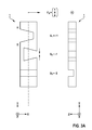
Fig. 1a zeigt ein planaraufgebautes Kraftumformerelement 1, montiert an einerKatheterspitze 3a einer (in dieser Figur nicht zu erkennenden) Ablationselektrodenleitung, und versehen mit aufgelöteten oderangebondeten Zuleitungen 5 sowie zwei rückseitigaufgepressten Leiterfahnen 7. Gestrichelt dargestellt ist eine im Gebrauchszustand vorhandene weich-elastische Kunststoffumspritzung 9. DasKraftumformerelement 1 umfasst im Wesentlichen einplattenförmiges Substrat 1a mit drei, im Querschnitt jeweils rechteckigen Ausnehmungen (etwa Ausfräsungen oder Laser-Gräben) 1b, 1c und 1d und einen mittig in Längserstreckung des Substrats fest verlegten FBG-Sensor 1e. Weitere Erläuterungen zum Aufbau und zur Funktionsweise des Kraftumformers finden sich weiter unten. -
Fig. 1b zeigt eine Außenansicht des distalen Endabschnittes einer Ablationselektrodenleitung 3 mit der bereits erwähnten Katheterspitze 3a, die mit dem Kraftumformer in Wirkverbindung steht, und einem sich daran anschließenden weich-elastischen Leitungskörper 3b, beispielsweise aus einem für Katheter oder Elektrodenleitungen gebräuchlichen Silikonmaterial.Auf dem Leitungskörper 3b sind in Abstand von der Katheterspitze bzw. dem distalen Ende und voneinander beabstandet zwei Ringelektroden 7' angeordnet, die durch Umwickeln des Leitungskörpers mit den inFig. 1a gezeigten Leiterfahnen 7 gebildet sind. - Im Übrigen sind Ablationselektrodenleitungen bzw. Ablationskatheter an sich bekannt, so dass von einer genaueren Beschreibung hier abgesehen werden kann. Es sei jedoch darauf hingewiesen, dass für die Ausführung mit einem integrierten Kraftumformer gemäß
Fig. 1a auf eine ausreichend weich-elastische Umhüllung zu achten ist, um die Abfühlcharakteristik des Kraftumformers bzw. Dehnmessstreifens nicht nachteilig zu beeinflussen. -
Fig. 2a und 2b zeigenden Kraftumformer 1, der ausdem Substrat 1a und dem FBG-Sensor 1e besteht, etwas genauer. Es ist zu erkennen, dass die drei als Sensorbereiche wirkenden (nicht separat mit Bezugsziffern bezeichneten) Sensorbereiche der FBG-Faser 1e jeweils einer der quaderförmigen bzw. imQuerschnitt rechteckigen Ausnehmungen EP 2 491 883 A1 dem planaren Substrat 1a gegenüber bisher bekannten zylindrischen Anordnungen Besonderheiten, die weiter unten erläutert werden.Das planare Substrat 1a hat gegenüber zylindrischen Substratkonstruktionen erhebliche fertigungstechnische Vorteile; insbesondere kann es mit an sich bekannten Ätztechniken oder XYgesteuerten Mikrofräsern gemäß bekannten Techniken der Mikrostrukturtechnik in effizienter und kostengünstiger Weise erzeugt werden. -
Fig. 2c zeigt beispielhaft und rein schematisch eine rückseitige Verdrahtung des Kraftum-former 1 (ohne die FBG-Faser 1e), zum Anschluss der Leiterflächen 7 sowie zweier distaler Kontaktflächen 5b, 5c, die etwa zur Stromversorgung bestimmter (nicht dargestellter) elektronischer Bauteile oder zum Anschluss einer Ablationselektrode vorgesehen sein können. Hierbei sind keine Zuleitungen zurKontaktfläche 5c zu erkennen; solche können insbesondere in einer unter der Substratoberfläche liegenden zweiten Verdrahtungsschicht angeordnet sein. Grundsätzlich ist es aber auch möglich, auf der hier zu erkennenden Oberfläche noch weitere Leitungen vorzusehen, mit denen jene Kontaktfläche 5c mit zusätzlichen proximalen Kontaktflächen 5a verbunden würde.
- Fig. 1a and 1b
- perspective views an overall schematic view of a sensor connection element or a distal end portion of a corresponding Ablationskatheters according to the invention in the form of a force transducer element, for example in an ablation electrode,
- Fig. 2a to 2c
- Detailed views of the sensor connection element according to
Fig. 1 and - Fig. 3a to 3c
- sketch-like detailed views of the substrate of the sensor connection element (power converter) in the idle state or under different force effects, to explain the function and calibration.
-
Fig. 1a shows a planar constructedforce transducer element 1, mounted on acatheter tip 3a (not visible in this figure) ablation electrode line, and provided with soldered or gebondeten leads 5 and two printed back on thetabs 7. Dashed lines shown in use is a soft-elastic Kunststoffumspritzung. 9 Theforce transducer element 1 essentially comprises a plate-shapedsubstrate 1a with three recesses (for example cut-outs or laser trenches) 1b, 1c and 1d which are rectangular in cross-section and anFBG sensor 1e fixed centrally in the longitudinal extent of the substrate. Further explanations on the structure and functioning of the power converter can be found below. -
Fig. 1b shows an external view of the distal end portion of an ablation electrode lead 3 with the already mentionedcatheter tip 3a, which is in operative connection with the force transducer, and a subsequent soft-elastic lead body 3b, for example, from a common for catheter or electrode leads silicone material. On thelead body 3b are at a distance from the catheter tip and the distal end and spaced apart two ring electrodes 7 'are arranged, which by wrapping the lead body with the inFig. 1a shown conductor lugs 7 are formed. - Incidentally, ablation electrode lines or ablation catheters are known per se, so that a more detailed description can be omitted here. It should be noted, however, that for execution with an integrated force transducer according to
Fig. 1a Care must be taken to ensure a sufficiently soft-elastic covering in order not to adversely affect the sensing characteristic of the force transducer or strain gauge. -
Fig. 2a and 2b show theforce transducer 1, which consists of thesubstrate 1 a and theFBG sensor 1 e, a little closer. It can be seen that the three sensor regions (not separately denoted by reference numerals) of theFBG fiber 1e are each assigned positionally to one of the rectangular or rectangular cross-section recesses 1b, 1c, 1d of thesubstrate 1a. Design and operation of such a single-fiber FBG sensor (hereinafter also referred to as FBG fiber) are from theEP 2 491 883 A1 planar substrate 1a, there are peculiarities compared with previously known cylindrical arrangements which will be explained below. The planar oneSubstrate 1a has considerable manufacturing advantages over cylindrical substrate constructions; in particular, it can be produced in an efficient and cost-effective manner by means of known etching techniques or XY-controlled microfrots according to known techniques of microstructure technology. -
Fig. 2c shows by way of example and purely schematically a rear wiring of the force transducer 1 (without theFBG fiber 1e), for connecting the conductor surfaces 7 and twodistal contact surfaces contact surface 5c to recognize; in particular, these can be arranged in a second wiring layer located below the substrate surface. In principle, however, it is also possible to provide further lines on the surface to be recognized here, with which thosecontact surface 5c would be connected to additionalproximal contact surfaces 5a.
Die Realisierung der Leiterbahnen zwischen den Leiterfahnen 7 und der distalen Kontaktfläche 5b und den proximalen Kontaktflächen 5a kann mit an sich bekannten Verfahren der Leiterplatten- bzw. Halbleitertechnologie erfolgen, also mit fotolithografischen Strukturierungs-, Beschichtungs- und Ätzprozessen oder in Dickschichttechnik o.ä.. Hier wirkt sich ein weiterer wesentlicher Vorteil der Erfindung aus, dass nämlich auf ausgereifte und hochproduktive planare Beschichtungs- und Strukturierungsprozesse zurückgegriffen werden kann.The realization of the interconnects between the conductor lugs 7 and the
Im Hinblick darauf, dass eine hochgenaue Kraftmessung die Kenntnis sensorspezifischer bzw. katheterspezifischer Daten des einzelnen Produkts in einer eingeschlossenen Auswertungseinheit erfordert, hat der Katheter gemäß einer weiteren Ausführung der Erfindung einen, insbesondere am oder nahe einem proximalen Ende angeordneten, Informationsträger mit spezifischer Kalibrierungsinformation. In einer Ausgestaltung ist der Informationsträger als RFID-Tag oder Barcode ausgebildet, welcher mit an sich bekannten und kostengünstigen Mitteln an der Signalverarbeitungseinheit leicht und zuverlässig ausgelesen werden kann.In view of the fact that a high-precision force measurement requires knowledge of sensor-specific or catheter-specific data of the individual product in an enclosed evaluation unit, the catheter according to a further embodiment of the invention has an information carrier with specific calibration information, in particular arranged at or near a proximal end. In one embodiment, the information carrier is designed as an RFID tag or bar code, which can be easily and reliably read out with known and inexpensive means on the signal processing unit.
Zur Berechnung eines 3D-Kraftvektors muss eine Kalibrierung des Sensorsystems stattfinden, indem der Sensor nacheinander mit drei zueinander senkrechten Kräften (Fx, Fy, Fz) belastet wird.To calculate a 3D force vector, a calibration of the sensor system must take place by loading the sensor in succession with three mutually perpendicular forces (Fx, Fy, Fz).
In der Theorie berechnen sich die Dehnungen ε1, ε2 und ε3 in den verteilten Sensorbereichen mit den Biegesteifigkeiten EI, den Biegemomenten Fl und den Abstand r zur dehnungsneutralen Faser wie folgt (


Mit drei Messungen, in denen drei zueinander senkrechte Kräfte verwendet werden, kann eine entsprechende Kalibrierungsmatrix berechnet werden: 
Dabei müssen die Biegesteifigkeiten EI und Abstände zur neutralen Faser r in dem Sensorhalter in der Art konstruiert werden, dass sich drei linear unabhängige Gleichungen ergeben. So ist es möglich einen 3D-Kraftvektor aus gemessenen Dehnungen einer beliebigen Kraftrichtung mit Hilfe der Kalibrierungsmatrix zu berechnen: 
Diese Kalibrierungsdaten werden optional im Katheter auf einem EEPROM, RFID oder einem 2D-Barcode gespeichert und von der Auswerteeinheit drahtlos, drahtgebunden oder beim 2D-Barcode optisch ausgelesen.These calibration data are optionally stored in the catheter on an EEPROM, RFID or a 2D barcode and optically read out by the evaluation unit wirelessly, by wire or by the 2D barcode.
Nachfolgend und unter Bezugnahme auf
Im Fall 1 lässt sich (im Idealfall) Gleichung 3 - unter Vertauschung der beiden Seiten - wie folgt schreiben: 
Im Fall 2 stellt sich die Gleichung wie folgt dar: 
Im Fall 3 stellt sich die Gleichung wie folgt dar: 
In der Praxis ist davon auszugehen, dass die Kraftkomponenten ungleich auf die Sensorbereiche übertragen werden; so ist etwa der Sensorbereich S1 sensitiver als beispielsweise S2, und der Sensorbereich S3 ist auch sensibel für X- und Y-Komponenten der einwirkenden Kraft. In der Realität gibt es generell ein Übersprechen zwischen den Sensorbereichen, d.h. jeder Sensorbereich ist auch in gewissem Maße sensibel für Krafteinwirkungen, die senkrecht zur Vorzugsachse seiner Sensitivität ausgerichtet sind. Dies wird mittels einer geeigneten Koeffizientenmatrix berücksichtigt, die beispielhaft die nachfolgende Form haben kann: 
Die Ausführung der Erfindung ist nicht auf die oben beschriebenen Beispiele und hervorgehobenen Aspekte beschränkt, sondern kann ebenso in einer Vielzahl von Abwandlungen erfolgen, die im Rahmen fachmännischen Handelns liegen. Beispielsweise können in der Ausführung als reines Anschlusselement - ohne Funktionalität eines Dehnmessstreifens des oben erläuterten oder eines ähnlichen Aufbaus - Ausnehmungen im Substrat etwa als Leiterzug-Unterbrechungen oder zur platzsparenden und geschützten Unterbringung von Schaltkreisen oder auch diskreten elektronischen Bauteilen dienen.The embodiment of the invention is not limited to the examples and highlighted aspects described above, but may also be made in a variety of variations, which are within the skill and skill of the art. For example, in the embodiment as a pure terminal element - without functionality of a strain gauge of the above-mentioned or a similar structure - recesses in the substrate serve as Leiterzug interruptions or space-saving and protected housing of circuits or discrete electronic components.
Claims (15)
Applications Claiming Priority (1)
| Application Number | Priority Date | Filing Date | Title |
|---|---|---|---|
| US201462010466P | 2014-06-11 | 2014-06-11 |
Publications (1)
| Publication Number | Publication Date |
|---|---|
| EP2954867A1 true EP2954867A1 (en) | 2015-12-16 |
Family
ID=53396174
Family Applications (1)
| Application Number | Title | Priority Date | Filing Date |
|---|---|---|---|
| EP15168296.0A Withdrawn EP2954867A1 (en) | 2014-06-11 | 2015-05-20 | Planar logic board for ablation catheter with force measurement functionality |
Country Status (2)
| Country | Link |
|---|---|
| US (1) | US9955917B2 (en) |
| EP (1) | EP2954867A1 (en) |
Families Citing this family (6)
| Publication number | Priority date | Publication date | Assignee | Title |
|---|---|---|---|---|
| US10813689B2 (en) * | 2015-11-25 | 2020-10-27 | Biosense Webster (Israel) Ltd. | Ablation catheter with radial force detection |
| DE102017105053B4 (en) * | 2017-03-09 | 2020-08-06 | Technische Universität Darmstadt | Integrated medical instrument for measuring forces in the distal area of a rod and manufacturing method of the same |
| US11033327B2 (en) * | 2017-10-30 | 2021-06-15 | St. Jude Medical, Cardiology Division, Inc. | Electrophysiology catheter with modular electrode structure |
| CN109459472B (en) * | 2018-11-07 | 2021-01-22 | 柳州国福科技有限公司 | Processing technology of humidity sensor |
| DE102019201169B4 (en) * | 2019-01-30 | 2022-02-17 | Kuka Deutschland Gmbh | Robot gripper with a force sensor |
| EP4216855A1 (en) * | 2020-09-23 | 2023-08-02 | VascoMed GmbH | Catheter device with a sensor device for measuring a force effect |
Citations (11)
| Publication number | Priority date | Publication date | Assignee | Title |
|---|---|---|---|---|
| US5343860A (en) * | 1989-02-06 | 1994-09-06 | Arzco Medical Systems, Inc. | Esophageal recording/pacing catheter with thermistor and cardiac imaging transceiver |
| US20030018273A1 (en) * | 1994-09-02 | 2003-01-23 | Jomed Inc. | Guidewire with pressure and temperature sensing capabilities |
| DE102006030407A1 (en) * | 2006-06-29 | 2008-01-03 | Werthschützky, Roland, Prof. Dr.-Ing. | Force sensor with asymmetric basic body for detecting at least one force component |
| WO2008003307A2 (en) | 2006-07-06 | 2008-01-10 | Werthschuetzky Roland | Force sensor for the detection of a force vector |
| US20080085074A1 (en) * | 2006-08-15 | 2008-04-10 | Suncall Corporation | Optical Pressure Sensor |
| US20080285909A1 (en) | 2007-04-20 | 2008-11-20 | Hansen Medical, Inc. | Optical fiber shape sensing systems |
| WO2009007857A2 (en) | 2007-05-24 | 2009-01-15 | Endosense Sa | Touch sensing catheter |
| WO2010088922A1 (en) | 2009-02-06 | 2010-08-12 | Abb Ag | Set of multiaxial force and torque sensor and assembling method |
| EP2491883A1 (en) | 2011-02-24 | 2012-08-29 | VascoMed GmbH | Catheter and catheter arrangement |
| US20120265102A1 (en) * | 2011-04-14 | 2012-10-18 | Giovanni Leo | Compact force sensor for catheters |
| DE202014100938U1 (en) * | 2013-10-25 | 2014-03-12 | Raoul Hecker | Pressure measuring device |
-
2015
- 2015-05-12 US US14/709,746 patent/US9955917B2/en active Active
- 2015-05-20 EP EP15168296.0A patent/EP2954867A1/en not_active Withdrawn
Patent Citations (11)
| Publication number | Priority date | Publication date | Assignee | Title |
|---|---|---|---|---|
| US5343860A (en) * | 1989-02-06 | 1994-09-06 | Arzco Medical Systems, Inc. | Esophageal recording/pacing catheter with thermistor and cardiac imaging transceiver |
| US20030018273A1 (en) * | 1994-09-02 | 2003-01-23 | Jomed Inc. | Guidewire with pressure and temperature sensing capabilities |
| DE102006030407A1 (en) * | 2006-06-29 | 2008-01-03 | Werthschützky, Roland, Prof. Dr.-Ing. | Force sensor with asymmetric basic body for detecting at least one force component |
| WO2008003307A2 (en) | 2006-07-06 | 2008-01-10 | Werthschuetzky Roland | Force sensor for the detection of a force vector |
| US20080085074A1 (en) * | 2006-08-15 | 2008-04-10 | Suncall Corporation | Optical Pressure Sensor |
| US20080285909A1 (en) | 2007-04-20 | 2008-11-20 | Hansen Medical, Inc. | Optical fiber shape sensing systems |
| WO2009007857A2 (en) | 2007-05-24 | 2009-01-15 | Endosense Sa | Touch sensing catheter |
| WO2010088922A1 (en) | 2009-02-06 | 2010-08-12 | Abb Ag | Set of multiaxial force and torque sensor and assembling method |
| EP2491883A1 (en) | 2011-02-24 | 2012-08-29 | VascoMed GmbH | Catheter and catheter arrangement |
| US20120265102A1 (en) * | 2011-04-14 | 2012-10-18 | Giovanni Leo | Compact force sensor for catheters |
| DE202014100938U1 (en) * | 2013-10-25 | 2014-03-12 | Raoul Hecker | Pressure measuring device |
Also Published As
| Publication number | Publication date |
|---|---|
| US20150359484A1 (en) | 2015-12-17 |
| US9955917B2 (en) | 2018-05-01 |
Similar Documents
| Publication | Publication Date | Title |
|---|---|---|
| EP2954867A1 (en) | Planar logic board for ablation catheter with force measurement functionality | |
| EP2491883B1 (en) | Catheter and catheter arrangement | |
| EP2711676B1 (en) | Fiber-optic force sensor, force measurement device and catheter | |
| EP2040636B1 (en) | Force sensor for the detection of a force vector | |
| DE102012202917B4 (en) | Force-moment sensor for measuring forces and moments | |
| EP2038627B1 (en) | Force sensor and method for detecting at least one force component | |
| DE102005003684B4 (en) | Fine adjustment mechanism for scanning probe microscopy | |
| DE3213319A1 (en) | DEVICE FOR MEASURING FORCE AND TORQUE COMPONENTS IN MULTIPLE DIRECTIONS | |
| EP0237598B1 (en) | Piezoresistive force-measuring element and its use in determining the forces acting upon a construction | |
| DE102017219901B3 (en) | Micromechanical z-inertial sensor | |
| EP3220116B1 (en) | Force sensor device | |
| DE102009028343A1 (en) | Sensor element and method for operating a sensor element | |
| DE112018008166T5 (en) | MULTI-AXIS BUTTON SENSOR | |
| DE102007026827A1 (en) | Single-axis force-torque-sensor for robot-supported manipulation and assembling processes, has extension measuring structure for detecting deformation, realized as part of metal lamination of printed circuit board in deformable area | |
| DE102018122522A1 (en) | Pressure sensor with improved strain gauge | |
| EP2554964B1 (en) | Pressure and temperature measuring device | |
| DE102010012701B4 (en) | Micro-force sensor | |
| DE60207864T2 (en) | PRESSURE SENSOR | |
| DE69725020T2 (en) | PRESSURE CONVERTER | |
| DE202016008911U1 (en) | Single or multi-axis force measuring device with a short deformation zone | |
| WO2020011956A1 (en) | Spatially resolving tactile sensor and production meodethod for a spatially resolving tactile sensor | |
| DE102011106894B3 (en) | Apparatus for simultaneous measurement of force and moment components, has deformable element that is provided with rod-shaped movable elements with bending joints and edges in cuboid form | |
| DE102016112352A1 (en) | Differential pressure sensor for determining a pressure measuring signal | |
| DE102006041224B4 (en) | Measuring arrangement with several strain gauge sensors and method for producing the measuring arrangement | |
| DE102016011709A1 (en) | Method for producing a sensor line and stock line for use in such a method |
Legal Events
| Date | Code | Title | Description |
|---|---|---|---|
| PUAI | Public reference made under article 153(3) epc to a published international application that has entered the european phase |
Free format text: ORIGINAL CODE: 0009012 |
|
| AK | Designated contracting states |
Kind code of ref document: A1 Designated state(s): AL AT BE BG CH CY CZ DE DK EE ES FI FR GB GR HR HU IE IS IT LI LT LU LV MC MK MT NL NO PL PT RO RS SE SI SK SM TR |
|
| AX | Request for extension of the european patent |
Extension state: BA ME |
|
| 17P | Request for examination filed |
Effective date: 20160615 |
|
| RBV | Designated contracting states (corrected) |
Designated state(s): AL AT BE BG CH CY CZ DE DK EE ES FI FR GB GR HR HU IE IS IT LI LT LU LV MC MK MT NL NO PL PT RO RS SE SI SK SM TR |
|
| STAA | Information on the status of an ep patent application or granted ep patent |
Free format text: STATUS: EXAMINATION IS IN PROGRESS |
|
| 17Q | First examination report despatched |
Effective date: 20190712 |
|
| STAA | Information on the status of an ep patent application or granted ep patent |
Free format text: STATUS: EXAMINATION IS IN PROGRESS |
|
| GRAP | Despatch of communication of intention to grant a patent |
Free format text: ORIGINAL CODE: EPIDOSNIGR1 |
|
| STAA | Information on the status of an ep patent application or granted ep patent |
Free format text: STATUS: GRANT OF PATENT IS INTENDED |
|
| RIC1 | Information provided on ipc code assigned before grant |
Ipc: A61B 18/14 20060101AFI20200710BHEP Ipc: A61B 90/00 20160101ALN20200710BHEP Ipc: A61N 1/06 20060101ALI20200710BHEP Ipc: A61N 1/05 20060101ALI20200710BHEP Ipc: A61B 34/20 20160101ALN20200710BHEP Ipc: A61B 17/00 20060101ALN20200710BHEP Ipc: G01L 1/24 20060101ALI20200710BHEP |
|
| INTG | Intention to grant announced |
Effective date: 20200731 |
|
| GRAJ | Information related to disapproval of communication of intention to grant by the applicant or resumption of examination proceedings by the epo deleted |
Free format text: ORIGINAL CODE: EPIDOSDIGR1 |
|
| STAA | Information on the status of an ep patent application or granted ep patent |
Free format text: STATUS: EXAMINATION IS IN PROGRESS |
|
| INTC | Intention to grant announced (deleted) | ||
| RIC1 | Information provided on ipc code assigned before grant |
Ipc: A61N 1/06 20060101ALI20201215BHEP Ipc: A61B 34/20 20160101ALN20201215BHEP Ipc: A61B 17/00 20060101ALN20201215BHEP Ipc: G01L 1/24 20060101ALI20201215BHEP Ipc: A61N 1/05 20060101ALI20201215BHEP Ipc: A61B 18/14 20060101AFI20201215BHEP Ipc: A61B 90/00 20160101ALN20201215BHEP |
|
| GRAP | Despatch of communication of intention to grant a patent |
Free format text: ORIGINAL CODE: EPIDOSNIGR1 |
|
| STAA | Information on the status of an ep patent application or granted ep patent |
Free format text: STATUS: GRANT OF PATENT IS INTENDED |
|
| INTG | Intention to grant announced |
Effective date: 20210201 |
|
| STAA | Information on the status of an ep patent application or granted ep patent |
Free format text: STATUS: THE APPLICATION IS DEEMED TO BE WITHDRAWN |
|
| 18D | Application deemed to be withdrawn |
Effective date: 20210612 |